Embed Size (px)
Citation preview
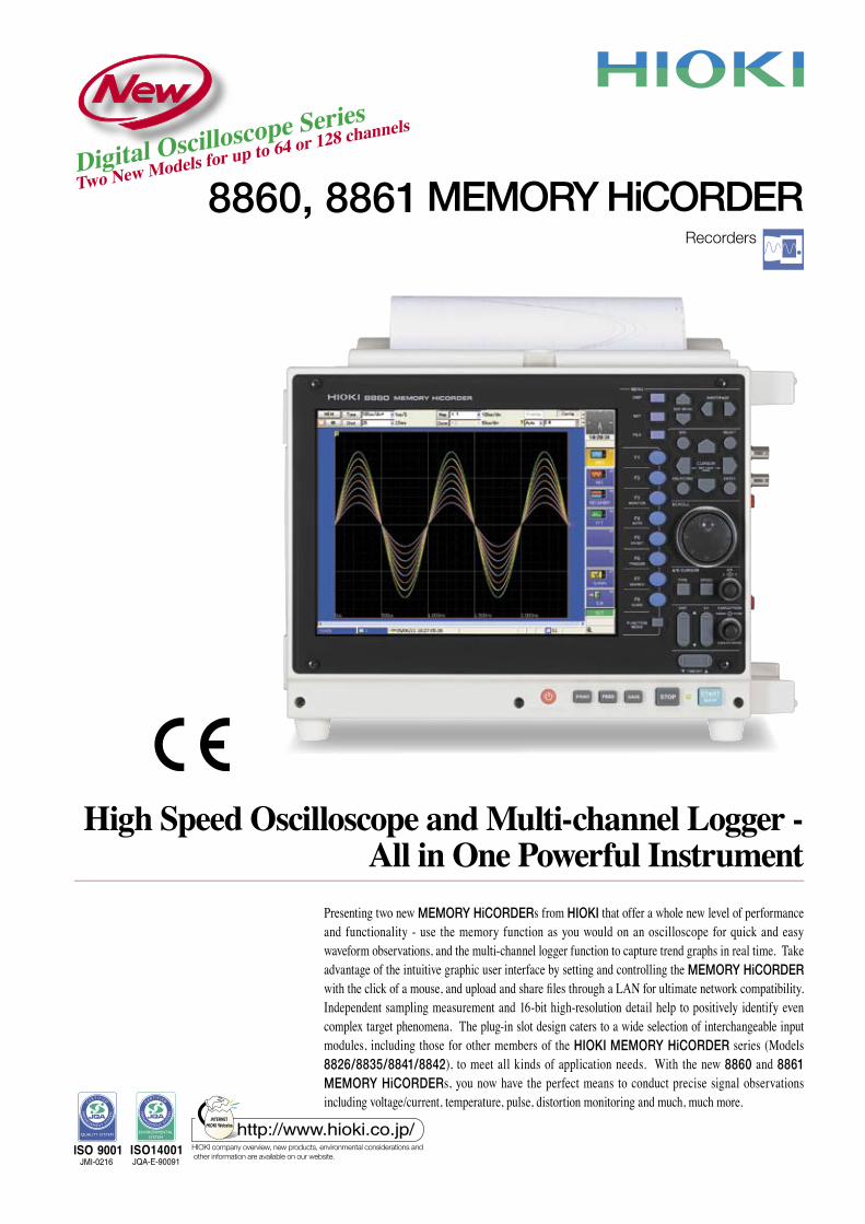
8860, 8861 MEMORY HiCORDERRecorders
High Speed Oscilloscope and Multi-channel Logger - All in One Powerful Instrument
Presenting two new MEMORY HiCORDERs from HIOKI that offer a whole new level of performance and functionality - use the memory function as you would on an oscilloscope for quick and easy waveform observations, and the multi-channel logger function to capture trend graphs in real time. Take advantage of the intuitive graphic user interface by setting and controlling the MEMORY HiCORDER with the click of a mouse, and upload and share fi les through a LAN for ultimate network compatibility. Independent sampling measurement and 16-bit high-resolution detail help to positively identify even complex target phenomena. The plug-in slot design caters to a wide selection of interchangeable input modules, including those for other members of the HIOKI MEMORY HiCORDER series (Models 8826/8835/8841/8842), to meet all kinds of application needs. With the new 8860 and 8861 MEMORY HiCORDERs, you now have the perfect means to conduct precise signal observations including voltage/current, temperature, pulse, distortion monitoring and much, much more.
Digital Oscilloscope Series
Two New Models for up to 64 or 128 channels
2
● High capacity memoryCompared to the previous Model 8841, the 8860 can be fitted with at least four times more direct access internal memory (32MW), and expanded up to 1GW, for an increase by a factor of 128. The 8861 can be customized to offer as much as 2GW (4GB) of memory, increasing the available recording time drastically.
● Dual SamplingTwo independent sampling speeds can be set up on one single MEMORY HiCORDER - allowing you to log at low sampling speeds with the scanner unit while simultaneously capturing high speed waveforms with others. Installing the scanner unit automatically programs the instrument to log at the lower sampling rate; otherwise, exclusively conduct analog measurements at both high and low sampling rates.
● Multi-channel loggingA new analog scanner unit developed exclusively for the 8860 series offers 16 isolated input channels, enabling up to 128 channels of simultaneous recording on the 8861 when 8 scanner units are installed. The delta-sigma based A/D converter provides an oversampling digital filter to greatly reduce noise and 50/60Hz hum interference that used to be a problem when measuring inverter type devices.
● Optional internal printerThe large recording width of the A4 size printer is useful for observing data in detail at the testing site. The printer was made an optional feature to enable product customization based on the user's unique application needs.
● Make complex settings and control with the click of a mouseSimply by connecting a mouse, the Windows-style graphic user interface offers a quick and intuitive means to adjust the MEMORY HiCORDER to the correct settings for your application.
● Collect data and control the MEMORY HiCORDER over a networkUse the FTP server function and the FTP client function (from version 2.00) to automatically transfer recorded data to a networked PC. The 8860 and 8861 can also be set up as a web server so that they can be remotely monitored and controlled from a computer.
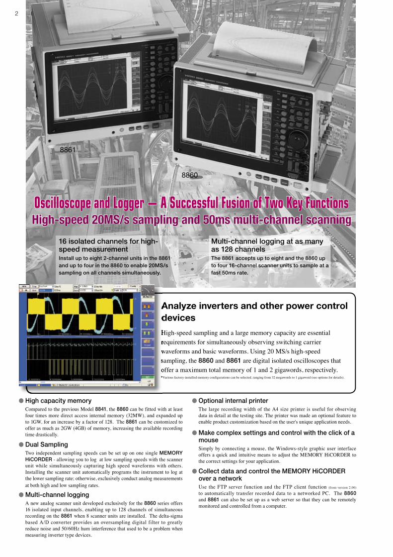
Multi-channel logging at as many as 128 channelsThe 8861 accepts up to eight and the 8860 up to four 16-channel scanner units to sample at a fast 50ms rate.
High-speed sampling and a large memory capacity are essential requirements for simultaneously observing switching carrier waveforms and basic waveforms. Using 20 MS/s high-speed sampling, the 8860 and 8861 are digital isolated oscilloscopes that offer a maximum total memory of 1 and 2 gigawords, respectively.*Various factory-installed memory configurations can be selected, ranging from 32 megawords to 1 gigaword (see options for details).
16 isolated channels for high-speed measurementInstall up to eight 2-channel units in the 8861 and up to four in the 8860 to enable 20MS/s sampling on all channels simultaneously.
8861
8860
Analyze inverters and other power control devices
High-speed sampling and a large memory capacity are essential requirements for simultaneously observing switching carrier waveforms and basic waveforms. Using 20 MS/s high-speed sampling, the offer a maximum total memory of 1 and 2 gigawords, respectively.*Various factory-installed memory configurations can be selected, ranging from 32 megawords to 1 gigaword (see options for details).
Analyze inverters and other power control devices
3
How long can I record to the internal direct access memory?
Input
Input
A/D converter
A/D converter
Isolation
Isolation
Memory load Screen displayPrint output
Inp
ut
volt
age
Sampling rateTime
Output waveform
Accurately capture complex waveforms- Digital sampling and trigger functions -
■ Clock input for external sampling *with MEMORY function
The sampling rate for the memory recorder can be controlled by the timing of an external clock signal (10 MS/s). This is useful for example to collect data synchronized to the running cycle of an engine.
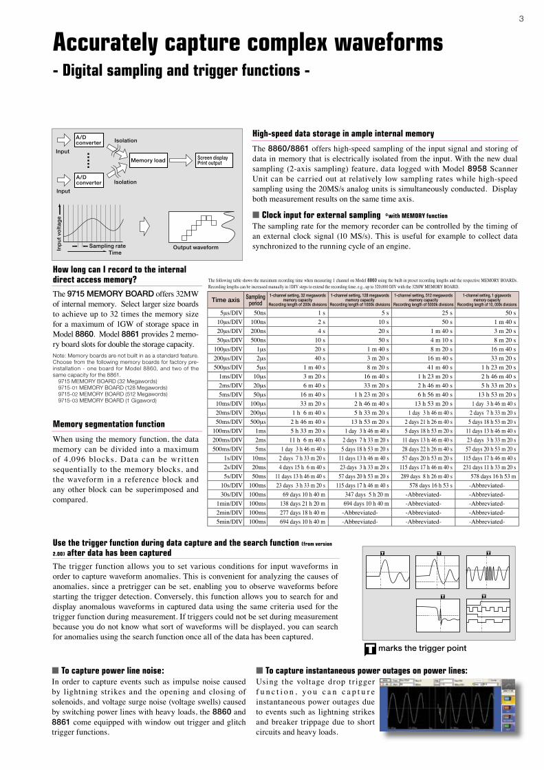
The following table shows the maximum recording time when measuring 1 channel on Model 8860 using the built-in preset recording lengths and the respective MEMORY BOARDs. Recording lengths can be increased manually in 1DIV steps to extend the recording time, e.g., up to 320,000 DIV with the 32MW MEMORY BOARD.
Time axis Sampling period
1-channel setting, 32 megawords memory capacity
Recording length of 200k divisions
1-channel setting, 128 megawords memory capacity
Recording length of 1000k divisions
1-channel setting, 512 megawords memory capacity
Recording length of 5000k divisions
1-channel setting, 1 gigawords memory capacity
Recording length of 10, 000k divisions
5μs/DIV 50ns 1 s 5 s 25 s 50 s10μs/DIV 100ns 2 s 10 s 50 s 1 m 40 s20μs/DIV 200ns 4 s 20 s 1 m 40 s 3 m 20 s50μs/DIV 500ns 10 s 50 s 4 m 10 s 8 m 20 s
100μs/DIV 1μs 20 s 1 m 40 s 8 m 20 s 16 m 40 s200μs/DIV 2μs 40 s 3 m 20 s 16 m 40 s 33 m 20 s500μs/DIV 5μs 1 m 40 s 8 m 20 s 41 m 40 s 1 h 23 m 20 s
1ms/DIV 10μs 3 m 20 s 16 m 40 s 1 h 23 m 20 s 2 h 46 m 40 s2ms/DIV 20μs 6 m 40 s 33 m 20 s 2 h 46 m 40 s 5 h 33 m 20 s5ms/DIV 50μs 16 m 40 s 1 h 23 m 20 s 6 h 56 m 40 s 13 h 53 m 20 s
10ms/DIV 100μs 33 m 20 s 2 h 46 m 40 s 13 h 53 m 20 s 1 day 3 h 46 m 40 s20ms/DIV 200μs 1 h 6 m 40 s 5 h 33 m 20 s 1 day 3 h 46 m 40 s 2 days 7 h 33 m 20 s50ms/DIV 500μs 2 h 46 m 40 s 13 h 53 m 20 s 2 days 21 h 26 m 40 s 5 days 18 h 53 m 20 s
100ms/DIV 1ms 5 h 33 m 20 s 1 day 3 h 46 m 40 s 5 days 18 h 53 m 20 s 11 days 13 h 46 m 40 s200ms/DIV 2ms 11 h 6 m 40 s 2 days 7 h 33 m 20 s 11 days 13 h 46 m 40 s 23 days 3 h 33 m 20 s500ms/DIV 5ms 1 day 3 h 46 m 40 s 5 days 18 h 53 m 20 s 28 days 22 h 26 m 40 s 57 days 20 h 53 m 20 s
1s/DIV 10ms 2 days 7 h 33 m 20 s 11 days 13 h 46 m 40 s 57 days 20 h 53 m 20 s 115 days 17 h 46 m 40 s2s/DIV 20ms 4 days 15 h 6 m 40 s 23 days 3 h 33 m 20 s 115 days 17 h 46 m 40 s 231 days 11 h 33 m 20 s5s/DIV 50ms 11 days 13 h 46 m 40 s 57 days 20 h 53 m 20 s 289 days 8 h 26 m 40 s 578 days 16 h 53 m
10s/DIV 100ms 23 days 3 h 33 m 20 s 115 days 17 h 46 m 40 s 578 days 16 h 53 s -Abbreviated-30s/DIV 100ms 69 days 10 h 40 m 347 days 5 h 20 m -Abbreviated- -Abbreviated-
1min/DIV 100ms 138 days 21 h 20 m 694 days 10 h 40 m -Abbreviated- -Abbreviated-2min/DIV 100ms 277 days 18 h 40 m -Abbreviated- -Abbreviated- -Abbreviated-5min/DIV 100ms 694 days 10 h 40 m -Abbreviated- -Abbreviated- -Abbreviated-
Memory segmentation function
When using the memory function, the data memory can be divided into a maximum of 4,096 blocks. Data can be wr it ten sequentially to the memory blocks, and the waveform in a reference block and any other block can be superimposed and compared.
Use the trigger function during data capture and the search function (from version
2.00) after data has been captured
marks the trigger point
The trigger function allows you to set various conditions for input waveforms in order to capture waveform anomalies. This is convenient for analyzing the causes of anomalies, since a pretrigger can be set, enabling you to observe waveforms before starting the trigger detection. Conversely, this function allows you to search for and display anomalous waveforms in captured data using the same criteria used for the trigger function during measurement. If triggers could not be set during measurement because you do not know what sort of waveforms will be displayed, you can search for anomalies using the search function once all of the data has been captured.
■ To capture power line noise:In order to capture events such as impulse noise caused by lightning strikes and the opening and closing of solenoids, and voltage surge noise (voltage swells) caused by switching power lines with heavy loads, the 8860 and 8861 come equipped with window out trigger and glitch trigger functions.
■ To capture instantaneous power outages on power lines:Using the voltage drop tr igger f u n c t i o n , y o u c a n c a p t u r e instantaneous power outages due to events such as lightning strikes and breaker trippage due to short circuits and heavy loads.
The 8860/8861 offers high-speed sampling of the input signal and storing of data in memory that is electrically isolated from the input. With the new dual sampling (2-axis sampling) feature, data logged with Model 8958 Scanner Unit can be carried out at relatively low sampling rates while high-speed sampling using the 20MS/s analog units is simultaneously conducted. Display both measurement results on the same time axis.
High-speed data storage in ample internal memory
The 9715 MEMORY BOARD offers 32MW of internal memory. Select larger size boards to achieve up to 32 times the memory size for a maximum of 1GW of storage space in Model 8860. Model 8861 provides 2 memo-ry board slots for double the storage capacity.Note: Memory boards are not built in as a standard feature. Choose from the following memory boards for factory pre-installation - one board for Model 8860, and two of the same capacity for the 8861. 9715 MEMORY BOARD (32 Megawords) 9715-01 MEMORY BOARD (128 Megawords) 9715-02 MEMORY BOARD (512 Megawords) 9715-03 MEMORY BOARD (1 Gigaword)
4
Capture Waveforms at Super High Speeds- 20 MS/s high-speed sampling for all channels using isolated input -
Three-phase inverter output system(Since the electric potential of the emitter is different for each phase, floating measurement is indispensable.)
Measuring the surge noise for power lines (using the 9322 DIFFERENTIAL PROBE in AC mode) If you select AC as the output mode, the signal connected to AC is divided to 1/1000 inside the probe
and output. Because the frequency range can be set between 1 kHz and 10 MHz, the output waveform
is displayed only when a voltage signal that includes a high waveform component is input, such as
surge noise superimposed on a 50/60 Hz commercial power line. Therefore, the 8860 and 8861 can
be used primarily to detect noise, as well as to measure the height of waves.
Rectified RMS voltages can be output (using the 9322 DIFFERENTIAL PROBE in RMS mode)
When RMS is selected as the output mode, the input signal voltage is divided to 1/1000, then true
RMS value rectification is performed, and the DC voltage output. RMS value rectification is performed
by analog circuitry, and because the bandwidth extends from 40 Hz to 100 kHz, signals that include
harmonic components can be accurately converted to RMS values not only for 50/60 Hz commercial
power lines, but for other waveforms containing harmonics, such as inverter output waveforms.
When measur ing the difference in electr ical potential between two signals that have a large overlapping common mode voltage, elect r ic shock may result if you are not using a measuring instrument with completely isolated input channels like the 8860/8861 MEMORY HiCORDER. F u r t h e r , w h e n m e a s u r i n g s i g n a l s w i t h a superimposed common mode voltage that includes high frequency components, such as inverter control and switching power circuit signals, the frequency characteristics for the common mode removal comparison of the isolated area greatly affect the measurement results. For example, when using the 8956 ANALOG UNIT, the peak-to-peak value for all waveform data can be measured or displayed in a range configuration of up to 280 V RMS using the memory function. If you want to measure voltages that exceed 280 V, you can use the optional 9322 DIFFERENTIAL PROBE to measure voltages up to 2000 V DC or 1000 V AC. Because a maximum voltage to ground of 1500 V AC/DC (CAT II) is possible, you can measure the common mode voltage for larger systems than before.
Can I use the 8860 to measure high voltages, such as inverter output?
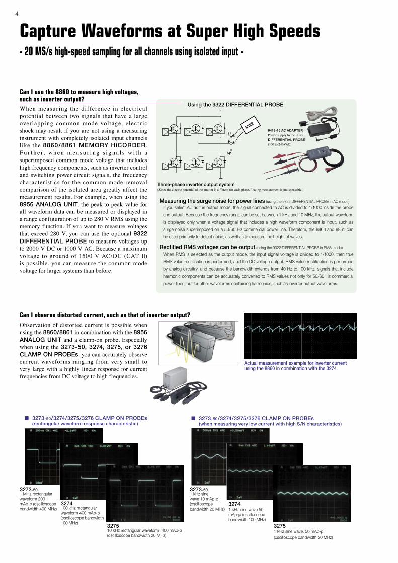
Observation of distorted current is possible when using the 8860/8861 in combination with the 8956 ANALOG UNIT and a clamp-on probe. Especially when using the 3273-50, 3274, 3275, or 3276 CLAMP ON PROBEs, you can accurately observe current waveforms ranging from very small to very large with a highly linear response for current frequencies from DC voltage to high frequencies.
Can I observe distorted current, such as that of inverter output?
Actual measurement example for inverter current using the 8860 in combination with the 3274
9418-15 AC ADAPTER Power supply to the 9322 DIFFERENTIAL PROBE (100 to 240VAC)
Using the 9322 DIFFERENTIAL PROBE
■ 3273-50/3274/3275/3276 CLAMP ON PROBEs (when measuring very low current with high S/N characteristics)
■ 3273-50/3274/3275/3276 CLAMP ON PROBEs (rectangular waveform response characteristic)
3274100 kHz rectangular waveform 400 mAp-p (oscilloscope bandwidth 100 MHz)
3273-501 MHz rectangular waveform 200 mAp-p (oscilloscope bandwidth 400 MHz)
327510 kHz rectangular waveform, 400 mAp-p (oscilloscope bandwidth 20 MHz)
32751 kHz sine wave, 50 mAp-p (oscilloscope bandwidth 20 MHz)
32741 kHz sine wave 50 mAp-p (oscilloscope bandwidth 100 MHz)
3273-501 kHz sine wave 10 mAp-p (oscilloscope bandwidth 20 MHz)
5
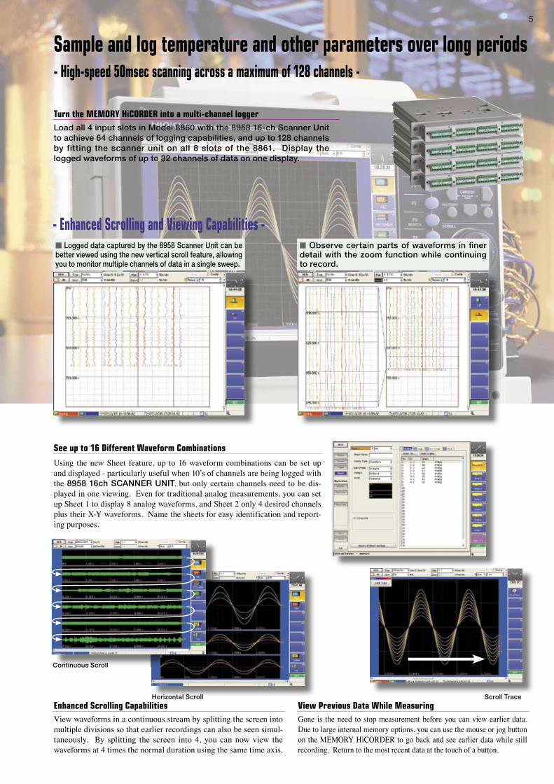
Turn the MEMORY HiCORDER into a multi-channel logger
View Previous Data While MeasuringEnhanced Scrolling Capabilities
Sample and log temperature and other parameters over long periods- High-speed 50msec scanning across a maximum of 128 channels -
■ Observe certain parts of waveforms in fi ner detail with the zoom function while continuing to record.
Load all 4 input slots in Model 8860 with the 8958 16-ch Scanner Unit to achieve 64 channels of logging capabilities, and up to 128 channels by fitting the scanner unit on all 8 slots of the 8861. Display the logged waveforms of up to 32 channels of data on one display.
■ Logged data captured by the 8958 Scanner Unit can be better viewed using the new vertical scroll feature, allowing you to monitor multiple channels of data in a single sweep.
Using the new Sheet feature, up to 16 waveform combinations can be set up and displayed - particularly useful when 10 s̓ of channels are being logged with the 8958 16ch SCANNER UNIT, but only certain channels need to be dis-played in one viewing. Even for traditional analog measurements, you can set up Sheet 1 to display 8 analog waveforms, and Sheet 2 only 4 desired channels plus their X-Y waveforms. Name the sheets for easy identification and report-ing purposes.
See up to 16 Different Waveform Combinations
View waveforms in a continuous stream by splitting the screen into multiple divisions so that earlier recordings can also be seen simul-taneously. By splitting the screen into 4, you can now view the waveforms at 4 times the normal duration using the same time axis.
Continuous Scroll
Horizontal Scroll
Gone is the need to stop measurement before you can view earlier data. Due to large internal memory options, you can use the mouse or jog button on the MEMORY HiCORDER to go back and see earlier data while still recording. Return to the most recent data at the touch of a button.
- Enhanced Scrolling and Viewing Capabilities -
Scroll Trace
6
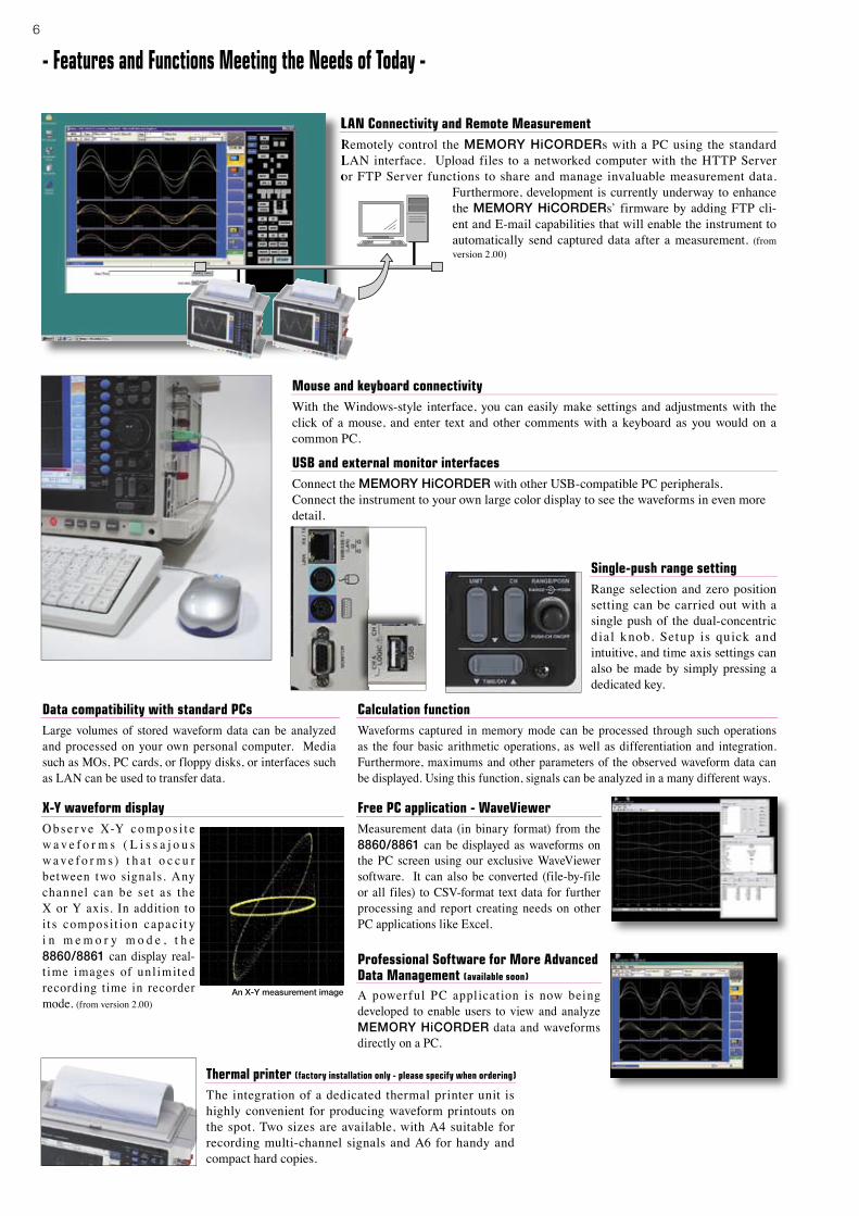
Remotely control the MEMORY HiCORDERs with a PC using the standard LAN interface. Upload files to a networked computer with the HTTP Server or FTP Server functions to share and manage invaluable measurement data.
Furthermore, development is currently underway to enhance the MEMORY HiCORDERsʼ firmware by adding FTP cli-ent and E-mail capabilities that will enable the instrument to automatically send captured data after a measurement. (from version 2.00)
LAN Connectivity and Remote MeasurementRemotely control the LAN interface. Upload files to a networked computer with the HTTP Server or FTP Server functions to share and manage invaluable measurement data.
LAN Connectivity and Remote Measurement
- Features and Functions Meeting the Needs of Today -
Thermal printer (factory installation only - please specify when ordering)
Connect the MEMORY HiCORDER with other USB-compatible PC peripherals. Connect the instrument to your own large color display to see the waveforms in even more detail.
USB and external monitor interfaces
Free PC application - WaveViewer
With the Windows-style interface, you can easily make settings and adjustments with the click of a mouse, and enter text and other comments with a keyboard as you would on a common PC.
Mouse and keyboard connectivity
Large volumes of stored waveform data can be analyzed and processed on your own personal computer. Media such as MOs, PC cards, or floppy disks, or interfaces such as LAN can be used to transfer data.
Data compatibility with standard PCsWaveforms captured in memory mode can be processed through such operations as the four basic arithmetic operations, as well as differentiation and integration. Furthermore, maximums and other parameters of the observed waveform data can be displayed. Using this function, signals can be analyzed in a many different ways.
Calculation function
Measurement data (in binary format) from the 8860/8861 can be displayed as waveforms on the PC screen using our exclusive WaveViewer software. It can also be converted (file-by-file or all files) to CSV-format text data for further processing and report creating needs on other PC applications like Excel.
An X-Y measurement image
O b s e r ve X-Y c o m p o s i t e w a v e f o r m s ( L i s s a j o u s w a v e f o r m s ) t h a t o c c u r between two signals. Any channel can be set as the X or Y axis. In addition to i t s composit ion capac it y i n m e m o r y m o d e , t h e 8860/8861 can display real-t ime images of unl imited recording time in recorder mode. (from version 2.00)
X-Y waveform display
Professional Software for More Advanced Data Management (available soon)
A power ful PC appl icat ion is now being developed to enable users to view and analyze MEMORY HiCORDER data and waveforms directly on a PC.
Range selection and zero position setting can be carried out with a single push of the dual-concentric dia l knob. Setup is quick and intuitive, and time axis settings can also be made by simply pressing a dedicated key.
Single-push range setting
The integration of a dedicated thermal printer unit is highly convenient for producing waveform printouts on the spot. Two sizes are available, with A4 suitable for recording multi-channel signals and A6 for handy and compact hard copies.
7
330mm(12.99 in)
30(1.18 in)
184.5mm(7.26 in)
272.
5mm
(10.
73 in
)18
4.5m
m(7
.26
in)
330mm(12.99 in)
284.5mm(11.20 in)
272.
5mm
(10.
73 in
)28
4.5m
m(1
1.20
in)
250m
m(9
.84
in)
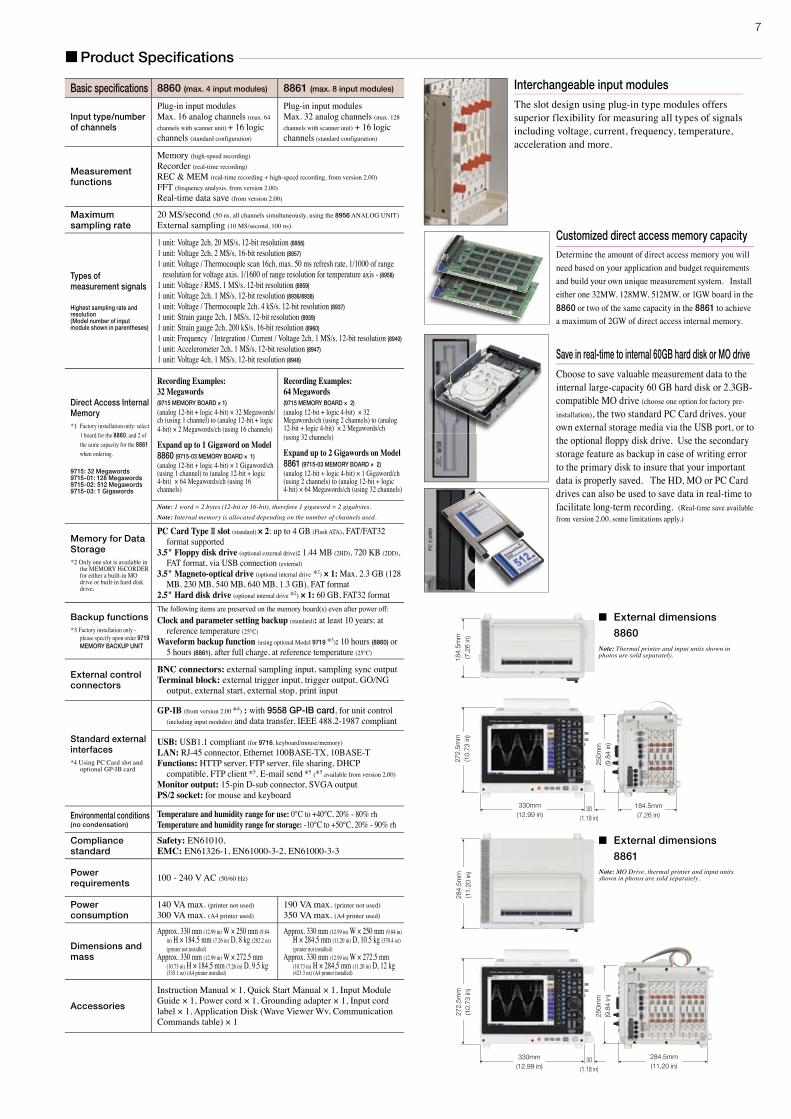
■ External dimensions
8860
■ External dimensions
8861Note: MO Drive, thermal printer and input units shown in photos are sold separately.
Note: Thermal printer and input units shown in photos are sold separately.
30(1.18 in)
250m
m(9
.84
in)
■ Product Specifications
Basic specifi cations 8860 (max. 4 input modules) 8861 (max. 8 input modules)
Input type/number of channels
Plug-in input modulesMax. 16 analog channels (max. 64 channels with scanner unit) + 16 logic channels (standard configuration)
Plug-in input modulesMax. 32 analog channels (max. 128 channels with scanner unit) + 16 logic channels (standard configuration)
Measurement functions
Memory (high-speed recording)Recorder (real-time recording)REC & MEM (real-time recording + high-speed recording, from version 2.00)FFT (frequency analysis, from version 2.00)Real-time data save (from version 2.00)
Maximum sampling rate
20 MS/second (50 ns, all channels simultaneously, using the 8956 ANALOG UNIT)External sampling (10 MS/second, 100 ns)
Types of measurement signals
Highest sampling rate and resolution(Model number of input module shown in parentheses)
1 unit: Voltage 2ch, 20 MS/s, 12-bit resolution (8956)
1 unit: Voltage 2ch, 2 MS/s, 16-bit resolution (8957)
1 unit: Voltage / Thermocouple scan 16ch, max. 50 ms refresh rate, 1/1000 of range resolution for voltage axis, 1/1600 of range resolution for temperature axis - (8958)
1 unit: Voltage / RMS, 1 MS/s, 12-bit resolution (8959)
1 unit: Voltage 2ch, 1 MS/s, 12-bit resolution (8936/8938)
1 unit: Voltage / Thermocouple 2ch, 4 kS/s, 12-bit resolution (8937)
1 unit: Strain gauge 2ch, 1 MS/s, 12-bit resolution (8939)
1 unit: Strain gauge 2ch, 200 kS/s, 16-bit resolution (8960)
1 unit: Frequency / Integration / Current / Voltage 2ch, 1 MS/s, 12-bit resolution (8940)
1 unit: Accelerometer 2ch, 1 MS/s, 12-bit resolution (8947)
1 unit: Voltage 4ch, 1 MS/s, 12-bit resolution (8946)
Direct Access Internal Memory*1 Factory installation only: select
1 board for the 8860, and 2 of the same capacity for the 8861 when ordering.
9715: 32 Megawords9715-01: 128 Megawords9715-02: 512 Megawords9715-03: 1 Gigawords
Recording Examples:32 Megawords (9715 MEMORY BOARD × 1)(analog 12-bit + logic 4-bit) × 32 Megawords/ch (using 1 channel) to (analog 12-bit + logic 4-bit) × 2 Megawords/ch (using 16 channels)
Expand up to 1 Gigaword on Model 8860 (9715-03 MEMORY BOARD × 1)(analog 12-bit + logic 4-bit) × 1 Gigaword/ch (using 1 channel) to (analog 12-bit + logic 4-bit) × 64 Megawords/ch (using 16 channels)
Recording Examples:64 Megawords (9715 MEMORY BOARD × 2)(analog 12-bit + logic 4-bit) × 32 Megawords/ch (using 2 channels) to (analog 12-bit + logic 4-bit) × 2 Megawords/ch (using 32 channels)
Expand up to 2 Gigawords on Model 8861 (9715-03 MEMORY BOARD × 2)(analog 12-bit + logic 4-bit) × 1 Gigaword/ch (using 2 channels) to (analog 12-bit + logic 4-bit) × 64 Megawords/ch (using 32 channels)
Note: 1 word = 2 bytes (12-bit or 16-bit), therefore 1 gigaword = 2 gigabytes.Note: Internal memory is allocated depending on the number of channels used.
Memory for Data Storage*2 Only one slot is available in
the MEMORY HiCORDER for either a built-in MO drive or built-in hard disk drive.
PC Card Type II slot (standard) × 2: up to 4 GB (Flash ATA), FAT/FAT32 format supported
3.5" Floppy disk drive (optional external drive): 1.44 MB (2HD), 720 KB (2DD), FAT format, via USB connection (external)
3.5" Magneto-optical drive (optional internal drive *2) × 1: Max. 2.3 GB (128 MB, 230 MB, 540 MB, 640 MB, 1.3 GB), FAT format
2.5" Hard disk drive (optional internal drive *2) × 1: 60 GB, FAT32 format
Backup functions*3 Factory installation only -
please specify upon order 9719 MEMORY BACKUP UNIT
The following items are preserved on the memory board(s) even after power off:Clock and parameter setting backup (standard): at least 10 years; at
reference temperature (25°C)Waveform backup function (using optional Model 9719 *3): 10 hours (8860) or
5 hours (8861), after full charge, at reference temperature (25°C)
External control connectors
BNC connectors: external sampling input, sampling sync outputTerminal block: external trigger input, trigger output, GO/NG
output, external start, external stop, print input
Standard external interfaces*4 Using PC Card slot and
optional GP-IB card
GP-IB (from version 2.00 *4) : with 9558 GP-IB card, for unit control (including input modules) and data transfer, IEEE 488.2-1987 compliant
USB: USB1.1 compliant (for 9716, keyboard/mouse/memory)LAN: RJ-45 connector, Ethernet 100BASE-TX, 10BASE-TFunctions: HTTP server, FTP server, file sharing, DHCP
compatible, FTP client *5, E-mail send *5 (*5 available from version 2.00)Monitor output: 15-pin D-sub connector, SVGA outputPS/2 socket: for mouse and keyboard
Environmental conditions(no condensation)
Temperature and humidity range for use: 0°C to +40°C, 20% - 80% rhTemperature and humidity range for storage: -10°C to +50°C, 20% - 90% rh
Compliance standard
Safety: EN61010, EMC: EN61326-1, EN61000-3-2, EN61000-3-3
Power requirements
100 - 240 V AC (50/60 Hz)
Power consumption
140 VA max. (printer not used)300 VA max. (A4 printer used)
190 VA max. (printer not used)350 VA max. (A4 printer used)
Dimensions and mass
Approx. 330 mm (12.99 in) W × 250 mm (9.84 in) H × 184.5 mm (7.26 in) D, 8 kg (282.2 oz) (printer not installed)
Approx. 330 mm (12.99 in) W × 272.5 mm (10.73 in) H × 184.5 mm (7.26 in) D, 9.5 kg (335.1 oz) (A4 printer installed)
Approx. 330 mm (12.99 in) W × 250 mm (9.84 in) H × 284.5 mm (11.20 in) D, 10.5 kg (370.4 oz) (printer not installed)
Approx. 330 mm (12.99 in) W × 272.5 mm (10.73 in) H × 284.5 mm (11.20 in) D, 12 kg (423.3 oz) (A4 printer installed)
Accessories
Instruction Manual × 1, Quick Start Manual × 1, Input Module Guide × 1, Power cord × 1, Grounding adapter × 1, Input cord label × 1, Application Disk (Wave Viewer Wv, Communication Commands table) × 1
Interchangeable input modulesThe slot design using plug-in type modules offers superior flexibility for measuring all types of signals including voltage, current, frequency, temperature, acceleration and more.
Customized direct access memory capacityDetermine the amount of direct access memory you will need based on your application and budget requirements and build your own unique measurement system. Install either one 32MW, 128MW, 512MW, or 1GW board in the 8860 or two of the same capacity in the 8861 to achieve a maximum of 2GW of direct access internal memory.
Save in real-time to internal 60GB hard disk or MO driveChoose to save valuable measurement data to the internal large-capacity 60 GB hard disk or 2.3GB-compatible MO drive (choose one option for factory pre-
installation), the two standard PC Card drives, your own external storage media via the USB port, or to the optional fl oppy disk drive. Use the secondary storage feature as backup in case of writing error to the primary disk to insure that your important data is properly saved. The HD, MO or PC Card drives can also be used to save data in real-time to facilitate long-term recording. (Real-time save available from version 2.00, some limitations apply.)
8
■ Product Specifications
Print/display section *6 Printer functions are available when optional printer unit is installed
Display 10.4 inch TFT color LCD (SVGA, 800 × 600 dots)
*6 Recording paper
9231 RECORDING PAPER: 216 mm (8.50 in) × 30 m (98.43 ft), thermal paper roll (when using A4 size 8995 printer unit)
9234 RECORDING PAPER: 112 mm (4.41 in) × 18 m (59.06 ft), thermal paper roll (when using A6 size 8995-01 printer unit)
*6 Recording width
9231 RECORDING PAPER: 200 mm (7.87 in) , full scale 20 divisions, 1 division = 10 mm (0.39 in) (when using A4 size 8995 printer unit)
9234 RECORDING PAPER: 100 mm (3.94 in) , full scale 10 divisions, 1 division = 10 mm (0.39 in) (when using A6 size 8995-01 printer unit)
*6 Paper feed density10 lines/mm (when using A4-size the 8995 printer unit), 8 lines/mm (when using A6-size the 8995-01 printer unit) * 20 lines/mm with "smoothed printing" memory function
*6 Recording speed Max. 20 mm (0.79 in)/sec
Trigger functions
Trigger sources
Analog input (up to 16 trigger sources can be set out of all analog channels), logic A - D, external trigger (2.5 V falling edge, or shorted terminals), manual trigger, timer trigger, selectable on/off for each manual trigger source, AND/OR between sources, set multiple trigger conditions for a single channel
Trigger types(analog)
Level: Triggering occurs when preset voltage level is crossed (upwards or downwards).
Window: Triggering occurs when window defined by upper and lower limit is entered or exited.
Period: Rising edge or falling edge cycle of preset voltage value is monitored and triggering occurs when defined cycle range is exceeded.
Glitch: Triggering occurs when pulse width from rising or falling edge of preset voltage value is underrun.
Slope: Triggering occurs when preset change degree (slope) is exceeded or underrun.
Voltage sag: Triggering occurs when voltage drops below peak voltage setting (for 50/60 Hz AC power lines only).
Event setting: Event count is performed for each source, and triggering occurs when a preset count is exceeded.
Level setting resolution 0.1% of full scale (full scale = 20 divisions)
Trigger types(logic) 0, 1 pattern setting, AND/OR setting for groups of 4 channels
Trigger filter(analog/logic)
OFF, setting range 0.1 - 10.0 divisions in 0.1-division steps (memory, recorder & memory), ON (10 ms)/OFF (recorder)
Other functions
Pre-trigger function, trigger output (BNC connectors, open-collector 5 V voltage, active Low), level indication during trigger standby, individual start and stop trigger setting for recorder/real-time save
Memory functions
Time axis5 μs - 5 min/division, 25 ranges or external sampling, time axis resolution 100 points/division, time axis zoom: ×2 to ×10 in 3 stages, compression: 1/2 - 1/500,000 in 17 stages
Sampling rateFixed: 1/100 of time axis range, Variable: external samplingSampling cycle can be used to set time axisTwo different sampling rate settings are possible
Recording length
With 32 MW memory board: manual setting in 1-division steps (max. 320,000 divisions *7) Or built-in presets of 25 - 200,000 divisions *7
With 128 MW memory board: manual setting in 1-division steps (max. 1,280,000 divisions *7) Or built-in presets of 25 - 1,000,000 divisions *7
With 512 MW memory board: manual setting in 1-division steps (max. 5,120,000 divisions *7) Or built-in presets of 25 - 5,000,000 divisions *7
With 1 GW memory board: manual setting in 1-division steps (max. 10,240,000 divisions *7) Or built-in presets of 25 - 10,000,000 divisions *7
*7 Maximum recording length or built-in preset length when using 1 channel (8860) or 2 channels (8861). Memory of 8861 is twice that of 8860, but recording length is the same.
Pre-triggerRecord data from before the trigger point, -100 to +100% of recording length (free setting in 1% steps)
Screen and printing
Split screen (1 - 8), X-Y screen (1, 2, 4 screens, max. 8 combined), sheet display (max. 32 channels per sheet), logging (print/display measurement data as digital values), voltage axis zoom (×2 to ×100), compression (×1/2 to ×1/10), overlay, zoom, variable display, vernier display
Calculation functionsWaveform parameter calculation, waveform parameter evaluation, waveform processing calculation
Memory splitting Divided use of memory space (up to 4096 divisions), sequential save
Recorder functions (X-Y function available from version 2.00)
Time axis
10 ms - 200 ms *8/division, 500 ms - 1 hour/division with 18 ranges, time axis resolution 100 points/division, time axis zoom: ×2 to ×5 in 2 stages, compression: 1/2 - 1/500 in 8 stages*8: Virtual record function: At 10 ms - 200 ms/division, printing in real time is not
possible, but waveform data are stored in memory and can be monitored on screen. Data are stored for 10,000 divisions before the end of measurement. At recording length settings other than "Continuous", the printer can be used simultaneously, for follow-up printing of waveforms.
Sampling rate 100 ns - 1 s in 8 stages (selectable in 1/100 of time axis range)
Recording length
With 32 MW memory board: manual setting in 1-division steps (max. 5,000 *9 divisions) or built-in presets of 25 - 5,000 divisions, continuous *8
With 128 MW memory board: manual setting in 1-division steps (max. 20,000 *9 divisions) or built-in presets of 25 - 20,000 divisions, continuous *8
With 512 MW memory board: manual setting in 1-division steps (max. 50,000 *9 divisions) or built-in presets of 25 - 80,000 divisions, continuous *8
With 1 GW memory board: manual setting in 1-division steps (max. 100,000 *9 divisions) or built-in presets of 25 - 160,000 divisions, continuous *8
*8: At time axis 10 ms - 200 ms/division and printer ON, Continuous setting cannot be selected*9: Memory of 8861 is twice than shown above, but recording length is the same.
X-Y sampling rate 300 μs fixed (dot), 300 μs - 25 ms (line)
X-Y axis resolution 20 dots/division (LCD, 1 screen), horizontal 80 dots/division × vertical 80 dots/division (printer)
Waveform recording
Store data for most recent 5,000 *10 divisions (with 32 MW memory) in memory. Backward scrolling and re-printing available.*10: 20,000 divisions with 128 MW, 80,000 divisions with 512 MW, 160,000 divisions
with 1 GW. Memory of 8861 is twice that of 8860, but recording length is the same.
Screen and printingSplit screen (1 - 8), X-Y screen (1, 2, 4 screens, max. 8 combined), sheet display (max. 32 channels per sheet), logging (print/display measurement data as digital values), voltage axis zoom (×2 to ×100), compression (×1/2 to ×1/10), variable display
REC & MEM function (function available from version 2.00)
Time axis(REC)
10 ms - 200 ms *11/division, 500 ms - 1 hour/division, 18 ranges, time axis resolution 100 points/division, sampling rate: same as sampling rate for memory function*11: Not available for virtual recording at 10 ms - 200 ms/division
Time axis(MEM)
10 μs - 5 min/division, 25 ranges, time axis resolution 100 points/division, sampling rate: 1/100 of time axis
Recording lengthREC: 25 - 2,000 *12 divisions, max. 50,000 divisions *12, continuousMEM: 25 - 5,000 *12 divisions, max. 100,000 divisions *12
*12: Depends on installed memory 32 MW - 1GW (free setting in 1-division steps also possible)
Waveform recording (REC)
Store data for most recent 2,000 *13 divisions (with 32 MW memory) in memory, allowing backscroll and reprinting*13: 10,000 divisions with 128 MW, 20,000 divisions with 512 MW, 50,000 divisions
with 1 GW. Memory of 8861 is twice that of 8860, but recording length is the same.divisions with 1 GW.
Screen and printing
Toggle REC/MEM waveform display, simultaneous display of REC/MEM waveform with split screen, split screen (1 - 8), sheet display (max. 32 channels per sheet), logging (print/display measurement data as digital values), zoom (with MEM), variable display
Memory splittingDivided use of memory space (up to 4096 divisions), sequential save, block search
Other functions Add-on recording (retain previous data at start and resume recording from previous data)
FFT function (function available from version 2.00)
Analysis mode
Storage waveform, linear spectrum, RMS spectrum, power spectrum, power spectrum density, cross power spectrum, auto-correlation function, histogram, transfer function, cross-correlation function, impulse response, coherence function, octave analysis
Analysis channels 1-channel FFT, 2-channel FFT in selected channels (up to 8 analysis functions)
Frequency range 133 mHz - 8 MHz, resolution 1/400, 1/800, 1/2000, 1/4000
Number of sampling points
1000, 2000, 5000, 10000 points
Analysis dataSelected from: Newly loaded data / Memory function waveform data / MEM waveform of REC & MEM function
Window functions
Rectangular, Hanning, Exponential, Hamming, Blackman, Blackman-Harris, Flat-top
Screen and printing
Split screen (1/2/4), Nyquist, array, logging (print/display measurement data as digital values), frequency axis zoom and left/right scrolling
AveragingTime axis / frequency axis simple averaging, exponential averaging, peak hold
9
■ Product Specifications
Real-time save function (function available from version 2.00)
Time axis(REC: compressed data)
10 ms - 200 ms *14/division, 500 ms - 1 hour/division, 18 ranges, time axis resolution 100 points/division, sampling rate: same as sampling rate for memory function*14: Not available for virtual recording at 10 ms - 200 ms/division
Time axis(MEM: real-time data)
100 μs - 5 min/division, 20 ranges (limited depending on store target and number of channels), time axis resolution 100 points/division, sampling rate: 1/100 of time axis
Save to Magneto-optical disk, hard disk, LAN, PC Card
Recording lengthDepending on available space on storage media / file system / number of channels / REC time axisSelectable in division steps up to maximum recording length
Screen and printing
During measurement: REC waveform, after measurement: toggle REC/MEM waveform display, simultaneous display of REC/MEM waveform with split screen, split screen (1 - 8), sheet display (max. 32 channels per sheet), logging (print/display measurement data as digital values), zoom, variable display
Memory transfer Memory function data can be transferred
■ Options (sold separately)For 8860/8861 only
■ Options (sold separately) For 8860/8861 only
8956 ANALOG UNIT (Accuracy at 23 ±5°C/73 ±9°F, 30 - 80 % rh after 30 minutes of warm-up time and zero-adjust; accuracy guaranteed for 1 year)
Measurement functions Number of channels: 2, for voltage measurement
Input connectorsIsolated BNC connector (input impedance 1 MΩ, input capacitance 40 pF), Max. rated voltage to earth: 300 V AC, DC (with input isolated from the unit, the maximum voltage that can be applied between input channel and chassis and between input channels without damage)
Measurement range
5 mV to 20 V/division, 12 ranges, full scale: 20 divisions, AC voltage for possible measurement/display using the memory function: 280 V rms, low-pass filter: 5/500/5k/1M Hz
Measurement resolution 1/100 of measurement range (using 12-bit A/D conversion; installed in 8860/8861)
Highest sampling rate 20 MS/s (simultaneous sampling in 2 channels)
AccuracyDC amplitude: ±0.4% of full scale (with filter 5 Hz)Zero position: ±0.1% of full scale (with filter 5 Hz, after zero adjustment)
Frequency characteristics DC to 10 MHz ±3 dB, with AC coupling: 7 Hz to 10 MHz ±3 dBInput coupling DC, GND, ACMax. allowable input 400 V DC (the maximum voltage that can be applied across input pins without damage)
Dimensions and mass: approx. 170 (6.69in) W × 20 (0.79in) H × 148.5 (5.85in) D mm, approx. 290 g (10.2 oz) Accessories: None
8957 HIGH-RESOLUTION UNIT (Accuracy at 23 ±5°C/73 ±9°F, 30 - 80 % rh after 30 minutes of warm-up time and zero-adjust; accuracy guaranteed for 1 year)
Measurement functions Number of channels: 2, for voltage measurement
Input connectorsIsolated BNC connector (input impedance 1 MΩ, input capacitance 40 pF), Max. rated voltage to earth: 300 V AC, DC (with input isolated from the unit, the maximum voltage that can be applied between input channel and chassis and between input channels without damage)
Measurement range
5 mV to 20 V/division, 12 ranges, full scale: 20 divisions, AC voltage for possible measurement/display using the memory function: 280 V rms, low-pass filter: 5/50/500/5k/50k Hz
Anti-aliasing filterIntegrated filter for suppressing aliasing distortion caused by FFT processing (automatic cutoff frequency setting/OFF)
Measurement resolution 1/1600 of measurement range (using 16-bit A/D conversion; installed in 8860/8861)
Highest sampling rate 2 MS/s (simultaneous sampling in 2 channels)
AccuracyDC amplitude: ±0.2% of full scale (with filter 5 Hz)Zero position: ±0.1% of full scale (with filter 5 Hz, after zero adjustment)
Frequency characteristics DC to 200 kHz ±3 dB, with AC coupling: 7 Hz to 200 kHz ±3 dBInput coupling DC, GND, ACMax. allowable input 400 V DC (the maximum voltage that can be applied across input pins without damage)
Dimensions and mass: approx. 170 (6.69in) W × 20 (0.79in) H × 148.5 (5.85in) D mm, approx. 310 g (10.9 oz) Accessories: None
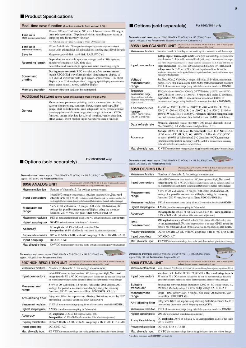
8958 16ch SCANNER UNIT (Accuracy at 23 ±5°C/73 ±9°F, 30 - 80 % rh after 1 hour of warm-up time and adjustment; accuracy guaranteed for 1 year)
Measurement functions Number of channels: 16, for voltage measurement/temperature measurement with thermocouple
Input connectors
Voltage input/Thermocouple input: screw-type terminal strip, recommended wire diameter *1, detachable terminal block (with cover) *1 Recommended cable, single-wire: 0.14 to 1.5 mm2, braided wire 0.14 to 1.0 mm2 (conductor wire diameter min. 0.18 mm), AWG 26 to 16Input impedance: 1 MΩ, 850 kΩ with line fault detection ON, Max. rated voltage to earth: 33 Vrms or 70 V DC (with input isolated from the unit, the maximum voltage that can be applied between input channel and chassis and between input channels without damage)
Voltage measurement range
5m, 50m, 500m, 2 V/division, 4 ranges, full scale: 20 divisions, measurement range: ±100% of full scale, digital filter: 50/60/10 Hz, measurement resolution 1/1600 of measurement range (using 16-bit A/D conversion; installed in 8860/8861)
Temperature measurement range(Upper and lower limit values depend on measurement input range of sensor)
10°C/division (-100°C/ to +200°C), 50°C/division (-200°C/ to +1000°C), 100°C/division (-200°C/ to +2000°C), 3 ranges, full scale: 20 divisions, digital filter: 50/60/10 Hz, measurement resolution 1/1000 of measurement range (using 16-bit A/D conversion; installed in 8860/8861)
Thermocouple range(JIS C 1602-1995)(ASTM E-988-96)
K: -200 to 1350°C, J: -200 to 1200°C, E: -200 to 1000°C, T: -200 to 400°C, N: -200 to 1300°C, R: 0 to 1700°C, S: 0 to 1700°C, B: 400 to 1800°C, W (WRe5-26): 0 to 2000°C, reference junction compensation: internal/ external (switchable), line fault detection ON/OFF switchable
Data refresh rate50 ms/all channels (digital filter OFF), 300 ms/all channels (digital filter 50/60 Hz), 1.4 s/all channels (digital filter 10 Hz)
Accuracy
Voltage: ±0.2% of full scale, thermocouple (K, J, E, T, N): ±0.05% of full scale ±1°C, (R, S, B, W): ±0.05% of full scale ±2°C (400°C or more), ±0.05% of full scale ±3.5°C (less than 400°C), reference junction compensation accuracy: ±1°C (added to measurement accuracy with internal reference junction compensation)
Max. allowable input 40 V DC (the maximum voltage that can be applied across input pins without damage)
Dimensions and mass: approx. 170 (6.69in) W × 20 (0.79in) H × 183 (7.20in) D mm, approx. 385 g (13.6 oz) Accessories: Flathead screwdriver × 1, short bar × 2
8959 DC/RMS UNIT (Accuracy at 23 ±5°C/73 ±9°F, 30 - 80 % rh after 30 minutes of warm-up time and zero-adjust; accuracy guaranteed for 1 year)
Measurement functions Number of channels: 2, for voltage measurement
Input connectorsIsolated BNC connector (input impedance 1 MΩ, input capacitance 30 pF), Max. rated voltage to earth: 370 V AC, DC (with input isolated from the unit, the maximum voltage that can be applied between input channel and chassis and between input channels without damage)
Measurement range
5 mV to 20 V/division, 12 ranges, full scale: 20 divisions, AC voltage for possible measurement/display using the memory function: 280 V rms, low-pass filter: 5/500/5k/100k Hz
Measurement resolution 1/80 of measurement range (using 12-bit A/D conversion; installed in 8860/8861)
Highest sampling rate 1 MS/s (simultaneous sampling in 2 channels)
AccuracyDC amplitude: ±0.4% of full scale (with filter 5 Hz), zero position: ±0.1% of full scale (with filter 5 Hz, after zero adjustment)
RMS measurement
RMS amplitude accuracy: ±1% of full scale (DC, 20 Hz - 1 kHz), ±3% of full scale (1 kHz - 100 kHz), response time: SLOW 5 s (rise time from 0 to 90% of full scale), MID 800 ms (rise time from 0 to 90% of full scale), FAST 100 ms (rise time from 0 to 90% of full scale), crest factor: 2
Frequency characteristics DC to 400 kHz ±3 dB, with AC coupling: 7 Hz to 400 kHz ±3 dBInput coupling DC, GND, ACMax. allowable input 400 V DC (the maximum voltage that can be applied across input pins without damage)
Dimensions and mass: approx. 170 (6.69in) W × 20 (0.79in) H × 148.5 (5.85in) D mm, approx. 290 g (10.2 oz) Accessories: None
8960 STRAIN UNIT (Accuracy at 23 ±5°C/73 ±9°F, 35 - 80 % rh after 1 hour of warm-up time and auto-balance; accuracy guaranteed for 1 year)
Measurement functions Number of channels: 2, for distortion measurement (electronic auto-balancing, balance adjustment range within ±10000 με)
Input connectorsVia adapter cable, TAJIMI PRC03-12A10-7M10.5, Max. rated voltage to earth: 33 Vrms or 70 V DC (with input isolated from the unit, the maximum voltage that can be applied between input channel and chassis and between input channels without damage)
Suitable transducer
Strain gauge converter, bridge impedance: 120 Ω to 1 kΩ (bridge voltage 2 V), 350 Ω to 1 kΩ (bridge voltage 5 V, 10 V), bridge voltage 2, 5, 10 ±0.05 V
Measurement range
20 με - 1000 με/division, 6 ranges, full scale: 20 divisions, low-pass filter: 5/10/100/1 kHz
Anti-aliasing filterIntegrated filter for suppressing aliasing distortion caused by FFT processing (automatic cutoff frequency setting/OFF)
Measurement resolution 1/1600 of measurement range (using 16-bit A/D conversion; installed in 8860/8861)
Highest sampling rate 200 kS/s (2-channel simultaneous sampling)
Accuracy After auto-balancing DC amplitude: ±(0.4% of full scale +2 με), zero position: ±0.1% of full scale (at 5 Hz filter ON)
Frequency characteristics DC to 20 kHz +1/-3 dBMax. allowable input 10 V DC (the maximum voltage that can be applied across input pins without damage)
* Available from main unit 8860/8861 version 1.06
Dimensions and mass: approx. 170 (6.69in) W × 20 (0.79in) H × 148.5 (5.85in) D mm, approx. 250 g (8.8 oz) Accessories: Adapter cable × 2
Additional features (Some functions available from version 2.00)
General
Measurement parameter printing, cursor measurement, scaling, current clamp setting, comment input, screen hard copy, list/gauge, start condition hold, auto setup, auto save, remote control (start/stop/print control), auto range, over-range indication, VIEW function, online help, key lock, level monitor, vernier function, offset cancel, event marker input, waveform search function
10
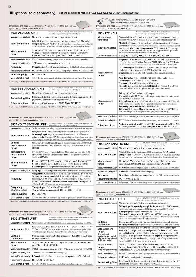
■ Options (sold separately) options common to Models 8720/8826/8835/8835-01/8841/8842/8860/8861
8936 ANALOG UNIT (Accuracy at 23 ±5°C/73 ±9°F, 35 - 80 % rh after 30 minutes of warm-up time and zero-adjust; accuracy guaranteed for 1 year)
Measurement functions Number of channels: 2, for voltage measurement
Input connectorsIsolated BNC connector (input impedance 1 MΩ, input capacitance 30 pF), Max. rated voltage to earth: 370 V AC, DC (with input isolated from the unit, the maximum voltage that can be applied between input channel and chassis and between input channels without damage)
Measurement range
5 mV to 20 V/division, 12 ranges, full scale: 20 divisions, AC voltage for possible measurement/display using the memory function: 280 V rms, low-pass filter: 5/500/5k/100k Hz
Measurement resolution 1/80 of measurement range (using 12-bit A/D conversion; installed in 8860/8861)
Highest sampling rate 1 MS/s (simultaneous sampling in 2 channels)
Accuracy DC amplitude: ±0.4% of full scale, zero position: ±0.1% of full scale (after zero adjustment)
Frequency characteristics DC to 400 kHz ±3 dB, with AC coupling: 7 Hz to 400 kHz ±3 dBInput coupling DC, GND, ACMax. allowable input 400 V DC (the maximum voltage that can be applied across input pins without damage)
* When using Model 8936 with serial number earlier than 041018234 on Models 8860 or 8861, residual noise will be 850 μVp-p.
Dimensions and mass: approx. 170 (6.69in) W × 20 (0.79in) H × 148.5 (5.85in) D mm, approx. 290 g (10.2 oz) Accessories: None
8938 FFT ANALOG UNIT (Accuracy at 23 ±5°C/73 ±9°F, 35 - 80 % rh after 30 minutes of warm-up time and zero-adjust; accuracy guaranteed for 1 year)
Measurement functions Number of channels: 2, for voltage measurement
Anti-aliasing filterIntegrated filter for suppressing aliasing distortion caused by FFT processing (automatic cutoff frequency setting/OFF)
Other functions Other specifications same as 8936 ANALOG UNIT
* When using Model 8938 with serial number earlier than 041132532 on Models 8860 or 8861, residual noise will be 1.4 mVp-p.
8937 VOLTAGE/TEMP UNIT (Accuracy at 23 ±5°C/73 ±9°F, 35 - 80 % rh after 1 hour of warm-up time and zero-adjust; accuracy guaranteed for 1 year)
Measurement functions Number of channels: 2, for voltage measurement/temperature measurement with thermocouple
Input connectors
Voltage input: metallic BNC connector (input impedance 1 MΩ, input capacitance 50 pF), thermocouple input: plug-in connector (input impedance min. 5.1 MΩ), Max. rated voltage to earth: 30 Vrms or 60 V DC (with input isolated from the unit, the maximum voltage that can be applied between input channel and chassis and between input channels without damage)
Voltage measurement range
500 μV to 2 V/division, 12 ranges, full scale: 20 divisions, low-pass filter: 5/500/5k/100k HzMeasurement resolution: 1/80 of measurement range (using 12-bit A/D conversion; installed in 8860/8861)
Temperature measurement range
10°C to 100°C/division, 4 ranges, full scale: 20 divisions, low-pass filter: 5/500 HzMeasurement resolution:1/80 of measurement range (using 12-bit A/D conversion; installed in 8860/8861)
Thermocouple range
K: -200 to 1350°C, E: -200 to 800°C, J: -200 to 1100°C, T: -200 to 400°C,N: -200 to 1300°C, R: 0 to 1700°C, S: 0 to 1700°C, B: 300 to 1800°C, Reference junction compensation: internal/ external (switchable)
Highest sampling rate Voltage input: 1 MS/s, Temperature measurement: 4 kS/s (2-channel simultaneous sampling)
Accuracy
Voltage input: DC amplitude ±0.4% of full scale, zero position ±0.15% of full scale, Temperature measurement (K, E, J, T, N): ±0.1% of full scale ±1°C, ±0.1% of full scale ±2°C (-200 to 0°C), (R, S): ±0.1% of full scale ±3°C, (B): ±0.1% of full scale ±4°C (400 to 1800°C) ,Reference junction compensation accuracy: ±0.1% of full scale ±1.5 °C (internal reference junction compensation)
Frequency characteristics
Voltage input: DC to 400 kHz + 1/-3 dBTemperature measurement: DC to 1 kHz + 1/-3 dB
Input coupling DC, GND, ACMax. allowable input 30 Vrms or 60 V DC (the maximum voltage that can be applied across input pins without damage)
* When using Model 8937 with serial number earlier than 041135257 on Models 8860 or 8861, residual noise will be 150 μVp-p.
Dimensions and mass: approx. 170 (6.69in) W × 20 (0.79in) H × 148.5 (5.85in) D mm, approx. 300 g (10.6 oz) Accessories: None
8939 STRAIN UNIT (Accuracy at 23 ±5°C/73 ±9°F, 35 - 80 % rh after 1 hour of warm-up time and auto-balance; accuracy guaranteed for 1 year)
Measurement functions Number of channels: 2, for distortion measurement (electronic auto-balancing, balance adjustment range within ±10000 με)
Input connectorsVia adapter cable, TAJIMI PRC03-12A10-7M10.5, Max. rated voltage to earth: 30 Vrms or 60 V DC (with input isolated from the unit, the maximum voltage that can be applied between input channel and chassis and between input channels without damage)
Suitable transducer
Strain gauge converter, bridge impedance: 120 Ω to 1 kΩ, bridge voltage 2 ±0.05 V
Measurement range
20 με - 1000 με/division, 6 ranges, full scale: 20 divisions, low-pass filter: 10/30/300/3 kHz
Measurement resolution 1/80 of measurement range (using 12-bit A/D conversion; installed in 8860/8861)
Highest sampling rate 1 MS/s (2-channel simultaneous sampling)
Accuracy After auto-balancing DC amplitude: ±(0.5% of full scale +2 με), zero position: ±0.5% of full scaleFrequency characteristics DC to 20 kHz +1/-3 dBMax. allowable input 10 V DC + AC peak (the maximum voltage that can be applied across input pins without damage)
Dimensions and mass: approx. 170 (6.69in) W × 20 (0.79in) H × 148.5 (5.85in) D mm, approx. 250 g (8.8 oz) Accessories: Adapter cable × 2
8940 F/V UNIT (Accuracy at 23 ±5°C/73 ±9°F, 35 - 80 % rh after 30 minutes of warm-up time and zero-adjust; accuracy guaranteed for 1 year)
Measurement functions
Number of channels: 2, for voltage input based frequency measurement, integration, pulse duty ratio, current (with optional clamp-on sensor), and voltage measurement
Input connectors
Metallic BNC connector (input impedance 1 MΩ, input capacitance 60 pF), sensor connector (dedicated connector for clamp-on sensor via adapter cable, common ground with recorder), Max. rated voltage to earth: 30 Vrms or 60 V DC (with input isolated from the unit, the maximum voltage that can be applied between input channel and chassis and between input channels without damage)
Compatible current sensors 9270, 9271, 9272, 9277, 9278, 9279, 3273, 3273-50
Measurement range
Frequency: DC to 100 kHz, with 0.05 Hz to 5 kHz/division, 11 ranges, 5 (r/min) to 500 (r/min)/division, 5 ranges, P50 Hz (40 to 60 Hz), P60 Hz (50 to 70 Hz) * Power line frequency measurement requires 9322 DIFFERENTIAL PROBE or 9303
PT., Accuracy: ±0.2% of full scale (except 5 kHz/division range), ±0.7% of full scale (5 kHz/division range), ±0.032 Hz (P50/P60 Hz range)
Integration: DC to 90 kHz, with 5 counts to 500 k counts/division, 11 ranges
Pulse duty ratio: 10 Hz - 100 kHz, with 100% of full scale, 1 range, Accuracy: ±1% of full scale (10 Hz - 10 kHz)
Threshold: -10 to +10 V (settable in 0.2-V steps)Full scale: 20 divisions, Max. allowable input: 30 Vrms or 60 V DC (the
maximum voltage that can be applied across input pins without damage)
Measurement range
Voltage: 0.5 mV to 2 V/division, 12 rangesCurrent: 5 mA to 100 A/division, 10 ranges, using current sensor (powered from the 8940, max. 4 sensors total)DC amplitude accuracy: ±0.4% of full scale, zero position ±0.15% of full scale (current measurement accuracy dependent on sensor accuracy/characteristics)Frequency characteristics: DC - 400 kHz ±3 dBFull scale: 20 divisions, Max. allowable input: 30 Vrms or 60 V DC (the maximum voltage that can be applied across input pins without damage)
Measurement resolution 1/80 of measurement range (installed in 8860/8861, excluding current range when using 9279)
Highest sampling rate 1 MS/s (2-channel simultaneous sampling), (frequency/duty ratio measurement: 1.125 μs cycle)
Other functionsVoltage input pull-up: ON (10 kΩ)/OFF, input coupling: DC, GND, AC (voltage/current), DC (others), low-pass filter: 5/500/5k/100k Hz
Dimensions and mass: approx. 170 (6.69in) W × 20 (0.79in) H × 148.5 (5.85in) D mm, approx. 300 g (10.6 oz) Accessories: None
9318 CONVERSION CABLE (to connect 9270 - 9272, 9277 - 9279 and 8940)9319 CONVERSION CABLE (to connect 3273, 3273-50 and 8940)
8946 4ch ANALOG UNIT (Accuracy at 23 ±5°C/73 ±9°F, 35 - 80 % rh after 30 minutes of warm-up time and zero-adjust; accuracy guaranteed for 1 year)
Measurement functions Number of channels: 4, for voltage measurement
Input connectorsMetallic BNC connector (input impedance 1 MΩ, input capacitance 15 pF), Max. rated voltage to earth: 30 Vrms or 60 V DC (with input isolated from the unit, the maximum voltage that can be applied between input channel and chassis and between input channels without damage)
Measurement range
10 mV to 2 V/division, 8 ranges, full scale: 20 divisions, low-pass filter, 5/500/5k/50k Hz, input coupling: DC, GND
Measurement resolution 1/80 of measurement range (using 12-bit A/D conversion; installed in 8860/8861)
Highest sampling rate 1 MS/s (4-channel simultaneous sampling)
Accuracy DC amplitude: ±0.5% of full scale, zero position: ±0.15% of full scale (after zero adjustment)
Frequency characteristics DC to 100 kHz ±3 dBMax. allowable input 30 Vrms or 60 V DC (the maximum voltage that can be applied across input pins without damage)
Dimensions and mass: approx. 170 (6.69in) W × 20 (0.79in) H × 148.5 (5.85in) D mm, approx. 310 g (10.9 oz) Accessories: None
8947 CHARGE UNIT (Accuracy at 23 ±5°C/73 ±9°F, 35 - 80 % rh after 1 hour of warm-up time and zero-adjust; accuracy guaranteed for 1 year)
Measurement functions Number of channels: 2, for acceleration measurement
Input connectors
Voltage input/integrated preamplifier input: metallic BNC connector (for voltage input: input impedance 1 MΩ, input capacitance 200 pF or less)Charge input: miniature connector (#10-32UNF)Max. rated voltage to earth: 30 Vrms or 60 V DC (with input isolated from the unit, the maximum voltage that can be applied between input channel and chassis and between input channels without damage)
Suitable transducer
Charge input: Charge-output type piezoelectric acceleration pick-up sensorInternal preamp input: Acceleration pick-up sensor with an internal preamp
Measurement rangeCharge input (miniature connector)Internal pre-amp input (BNC connector)
50 m (m/s2)/division to 10 k (m/s2)/division, 12 ranges × 6 types, charge input sensitivity: 0.1 - 10 pC/(m/s2), integrated pre-amplifier input: 0.1 - 10 mV/(m/s2), amplitude accuracy: ±2% of full scale, frequency characteristics: 1 to 50 kHz, +1/-3 dB, low-pass filter: 500/5k Hz, pre-amplifier drive power source: 2 mA ±20%, +15 V ±5%, maximum input charge: ±500 pC (high-sensitivity setting, 6 ranges), ±50000 pC (low-sensitivity setting, 6 ranges)
Measurement rangeVoltage input (BNC connector)
500 μV to 2 V/division, 12 ranges, DC amplitude accuracy: ±0.4% of full scale, frequency characteristics: DC to 400 kHz, +1/-3 dB, low-pass filter: 5/500/5k/100k Hz, input coupling: DC, GND, AC, Max. allowable input: 30 Vrms or 60 V DC
Measurement resolution 1/80 to 1/32 of measurement range (depending on measurement sensitivity; installed in 8860/8861)
Highest sampling rate 1 MS/s (2-channel simultaneous sampling)
Anti-aliasing filterIntegrated filter for suppressing aliasing distortion caused by FFT processing (automatic cutoff frequency setting/OFF)
* When using Model 8947 with serial number earlier than 040933650 on Models 8860 or 8861, residual noise will be 200 μVp-p.
Dimensions and mass: approx. 170 (6.69in) W × 20 (0.79in) H × 148.5 (5.85in) D mm, approx. 310 g (10.9 oz) Accessories: None
11
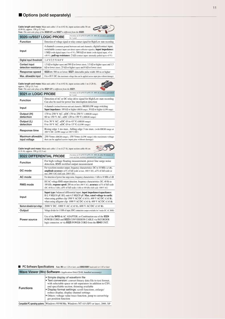
■ Options (sold separately)
9320-10/9327 LOGIC PROBE (Accuracy at 23 ±5°C/73 ±9°F, 35 - 80% rh; accuracy guaranteed for 1 year)
Function Detection of voltage signal or relay contact signal for High/Low state recording
Input
4 channels (common ground between unit and channels), digital/contact input, switchable (contact input can detect open-collector signals), input impedance: 1 MΩ (with digital input, 0 to +5 V), 500 kΩ or more (with digital input, +5 to +50 V), pull-up resistance: 2 kΩ (contact input: internally pulled up to +5 V)
Digital input threshold 1.4 V/2.5 V/4.0 V
Contact input detection resistance
1.5 kΩ or higher (open) and 500 Ω or lower (short), 3.5 kΩ or higher (open) and 1.5 kΩ or lower (short), 25 kΩ or higher (open) and 8 kΩ or lower (short)
Response speed 9320-01: 500 ns or lower, 9327: detectable pulse width 100 ns or higherMax. allowable input 0 to +50 V DC (the maximum voltage that can be applied across input pins without damage)
Cable length and mass: Main unit cable 1.5 m (4.92 ft), input section cable 30 cm (0.98 ft), approx. 150 g (5.3 oz) Note: The unit-side plug of the 9320-01 and 9327 is different from the 9320.
9321-01 LOGIC PROBE (Accuracy at 23 ±5°C/73 ±9°F, 35 - 80% rh; accuracy guaranteed for 1 year)
FunctionDetection of AC or DC relay drive signal for High/Low state recordingCan also be used for power line interruption detection
Input4 channels (isolated between unit and channels), HIGH/LOW range switchingInput impedance: 100 kΩ or higher (HIGH range), 30 kΩ or higher (LOW range)
Output (H) detection
170 to 250 V AC, ±DC (70 to 250 V ) (HIGH range)60 to 150 V AC, ±DC (20 to 150 V) (HIGH range)
Output (L) detection
0 to 30 V AC, ±DC (0 to 43 V) (HIGH range)0 to 10 V AC, ±DC (0 to 15 V) (LOW range)
Response time Rising edge 1 ms max., falling edge 3 ms max. (with HIGH range at 200 V DC, LOW range at 100 V DC)
Maximum allowable input voltage
250 Vrms (HIGH range), 150 Vrms (LOW range) (the maximum voltage that can be applied across input pins without damage)
Cable length and mass: Main unit cable 1.5 m (4.92 ft), input section cable 1 m (3.28 ft), approx. 320 g (11.3 oz)Note: The unit-side plug of the 9321-01 is different from the 9321.
9322 DIFFERENTIAL PROBE (Accuracy at 23 ±5°C/73 ±9°F, 35 - 80% rh, after 30 minutes of warm-up time; accuracy guaranteed for 1 year)
FunctionFor high-voltage floating measurement, power line surge noise detection, RMS rectified output measurement
DC modeFor waveform monitor output, frequency characteristics: DC to 10 MHz (±3 dB), amplitude accuracy: ±1% of full scale (at max. 1000 V DC), ±3% of full scale (at max. 2000 V DC) (full scale: 2000 V DC)
AC mode For detection of power line surge noise, frequency characteristics: 1 kHz to 10 MHz ±3 dB
RMS modeDC/AC voltage RMS output detection, frequency characteristics: DC, 40 Hz to 100 kHz, response speed: 200 ms or less (400 V AC), accuracy: ±1% of full scale (DC, 40 Hz to 1 kHz), ±4% of full scale (1 kHz to 100 kHz) (full scale: 1000 V AC)
Input
Input type: balanced differential input, input impedance/capacitance: H-L 9 MΩ/10 pF, H/L-unit 4.5 MΩ/20 pF, Max. rated voltage to earth: when using grabber clip 1500 V AC/DC (CAT II ), 600 V AC/DC (CAT III), when using alligator clip: 1000 V AC/DC (CAT II), 600 V AC/DC (CAT III)
Maximum allowable input voltage 2000 V DC, 1000 V AC (CAT II), 600 V AC/DC (CAT III)
Output Voltage divider for 1/1000 of input, BNC connectors (output switchable for 3 modes DC, AC, RMS)
Power sourceUse of the 9418-15 AC ADAPTER, or Combination use of the 9324 POWER CORD and 9323 CONVERSION CABLE via HiCORDER logic connector, or via 9325 POWER CORD from the 8940 UNIT.
Cable length and mass: Main unit cable 1.3 m (4.27 ft), input section cable 46 cm (1.51 ft), approx. 350 g (12.3 oz)
■ PC Software Specifications Note: Wv ver 1.20 or later, and 8860/8861 main unit ver 1.03 or later
Wave Viewer (Wv) Software (Application Disk CD-R, bundled accessory)
Functions
• Simple display of waveform file • Text conversion: convert binary data file to text format,
with selectable space or tab separators in addition to CSV, and specifiable section, thinning available
• Display format settings: scroll functions, enlarge/reduce display, display channel settings
• Others: voltage value trace function, jump to cursor/trig-ger position function
Compatible PC operating systems Windows 95/98/Me, Windows NT 4.0 (SP3 or later), 2000, XP
12
HEAD OFFICE :81 Koizumi, Ueda, Nagano, 386-1192, JapanTEL +81-268-28-0562 / FAX +81-268-28-0568 E-mail: [email protected]
HIOKI USA CORPORATION :6 Corporate Drive, Cranbury, NJ 08512 USATEL +1-609-409-9109 / FAX +1-609-409-9108E-mail: [email protected]
DISTRIBUTED BY
All information correct as of Jul. 29, 2005. All specifications are subject to change without notice. 8860E3-57E-10P Printed in Japan
Shanghai Representative Office :1704 Shanghai Times Square Office93 Huaihai Zhong RoadShanghai, 200021, P.R.ChinaTEL +86-21-6391-0090, 0092FAX +86-21-6391-0360E-mail: [email protected]
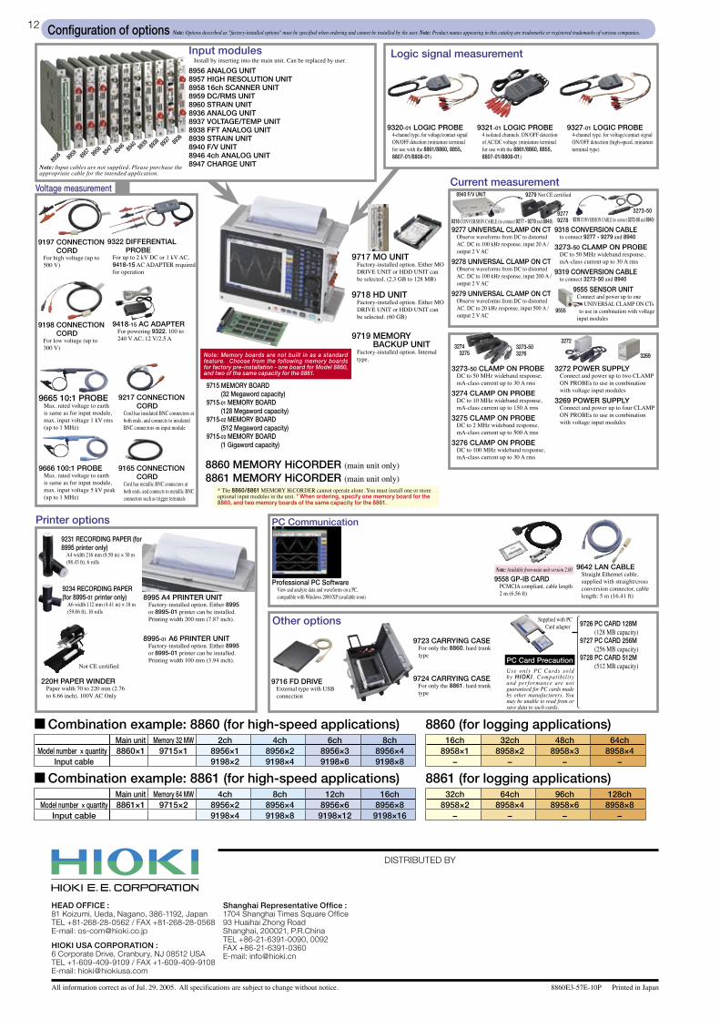
Configuration of options Note: Options described as "factory-installed options" must be specified when ordering and cannot be installed by the user. Note: Product names appearing in this catalog are trademarks or registered trademarks of various companies.
Printer options
Logic signal measurement
Voltage measurementCurrent measurement
Input modulesInstall by inserting into the main unit. Can be replaced by user.
8956 ANALOG UNIT8957 HIGH RESOLUTION UNIT8958 16ch SCANNER UNIT8959 DC/RMS UNIT8960 STRAIN UNIT8936 ANALOG UNIT8937 VOLTAGE/TEMP UNIT8938 FFT ANALOG UNIT8939 STRAIN UNIT8940 F/V UNIT8946 4ch ANALOG UNIT8947 CHARGE UNITNote: Input cables are not supplied. Please purchase the
appropriate cable for the intended application.
9715 MEMORY BOARD (32 Megaword capacity)9715-01 MEMORY BOARD (128 Megaword capacity)9715-02 MEMORY BOARD (512 Megaword capacity)9715-03 MEMORY BOARD (1 Gigaword capacity)
9320-01 LOGIC PROBE4-channel type, for voltage/contact signal ON/OFF detection (miniature terminal for use with the 8861/8860, 8855, 8807-01/8808-01)
9321-01 LOGIC PROBE4 isolated channels, ON/OFF detection of AC/DC voltage (miniature terminal for use with the 8861/8860, 8855, 8807-01/8808-01)
9717 MO UNITFactory-installed option. Either MO DRIVE UNIT or HDD UNIT can be selected. (2.3 GB to 128 MB)
9718 HD UNITFactory-installed option. Either MO DRIVE UNIT or HDD UNIT can be selected. (60 GB)
8860 MEMORY HiCORDER (main unit only)8861 MEMORY HiCORDER (main unit only)
* The 8860/8861 MEMORY HiCORDER cannot operate alone. You must install one or more optional input modules in the unit. * When ordering, specify one memory board for the 8860, and two memory boards of the same capacity for the 8861.
9197 CONNECTION CORD
For high voltage (up to 500 V)
9198 CONNECTION CORD
For low voltage (up to 300 V)
9322 DIFFERENTIAL PROBE
For up to 2 kV DC or 1 kV AC, 9418-15 AC ADAPTER required for operation
9418-15 AC ADAPTERFor powering 9322, 100 to 240 V AC, 12 V/2.5 A
9665 10:1 PROBEMax. rated voltage to earth is same as for input module, max. input voltage 1 kV rms (up to 1 MHz)
9666 100:1 PROBEMax. rated voltage to earth is same as for input module, max. input voltage 5 kV peak (up to 1 MHz)
9217 CONNECTION CORD
Cord has insulated BNC connectors at both ends, and connects to insulated BNC connectors on input module
9165 CONNECTION CORD
Cord has metallic BNC connectors at both ends, and connects to metallic BNC connectors such as trigger terminals
9327-01 LOGIC PROBE4-channel type, for voltage/contact signal ON/OFF detection (high-speed, miniature terminal type)
9719 MEMORY BACKUP UNIT
Factory-installed option. Internal type.
■ Combination example: 8860 (for high-speed applications) 8860 (for logging applications)Main unit Memory 32 MW 2ch 4ch 6ch 8ch 16ch 32ch 48ch 64ch
Model number × quantity 8860×1 9715×1 8956×1 8956×2 8956×3 8956×4 8958×1 8958×2 8958×3 8958×4Input cable 9198×2 9198×4 9198×6 9198×8 − − − −
■ Combination example: 8861 (for high-speed applications) 8861 (for logging applications)Main unit Memory 64 MW 4ch 8ch 12ch 16ch 32ch 64ch 96ch 128ch
Model number × quantity 8861×1 9715×2 8956×2 8956×4 8956×6 8956×8 8958×2 8958×4 8958×6 8958×8Input cable 9198×4 9198×8 9198×12 9198×16 − − − −
8995 A4 PRINTER UNITFactory-installed option. Either 8995 or 8995-01 printer can be installed. Printing width 200 mm (7.87 inch).
9231 RECORDING PAPER (for 8995 printer only)
A4 width 216 mm (8.50 in) × 30 m (98.43 ft), 6 rolls
9234 RECORDING PAPER (for 8995-01 printer only)
A6 width 112 mm (4.41 in) × 18 m (59.06 ft), 10 rolls
8995-01 A6 PRINTER UNITFactory-installed option. Either 8995 or 8995-01 printer can be installed. Printing width 100 mm (3.94 inch).
220H PAPER WINDERPaper width 70 to 220 mm (2.76 to 8.66 inch), 100V AC Only
Not CE certified
Note: Memory boards are not built in as a standard feature. Choose from the following memory boards for factory pre-installation - one board for Model 8860, and two of the same capacity for the 8861.
Other options
9716 FD DRIVEExternal type with USB connection
9642 LAN CABLEStraight Ethernet cable, supplied with straight/cross conversion connector, cable length: 5 m (16.41 ft)
9723 CARRYING CASEFor only the 8860, hard trunk type
9724 CARRYING CASEFor only the 8861, hard trunk type
9558 GP-IB CARDPCMCIA compliant, cable length 2 m (6.56 ft)
9726 PC CARD 128M (128 MB capacity)9727 PC CARD 256M (256 MB capacity)9728 PC CARD 512M (512 MB capacity)
PC Card PrecautionUse on ly PC Cards so ld by HIOKI . Compat ib i l i ty and per formance are not guaranteed for PC cards made by other manufacturers. You may be unable to read from or save data to such cards.
Professional PC SoftwareView and analyze data and waveforms on a PC, compatible with Windows 2000/XP (available soon)
PC Communication
Supplied with PC Card adapter
Note: Available from main unit version 2.00
8957
8959
8958 89
56 8947 89
46 8940 89
39 8938 89
37 8936
3272
32693273-503276
3274 3275
9555
9279 Not CE certified
92779278
9555 SENSOR UNITConnect and power up to one
UNIVERSAL CLAMP ON CTs to use in combination with voltage
input modules
9318 CONVERSION CABLE (to connect 9277 - 9279 and 8940)
3273-50
8940 F/V UNIT
9277 UNIVERSAL CLAMP ON CTObserve waveforms from DC to distorted AC. DC to 100 kHz response, input 20 A / output 2 V AC
9278 UNIVERSAL CLAMP ON CTObserve waveforms from DC to distorted AC. DC to 100 kHz response, input 200 A / output 2 V AC
9279 UNIVERSAL CLAMP ON CTObserve waveforms from DC to distorted AC. DC to 20 kHz response, input 500 A / output 2 V AC
9318 CONVERSION CABLEto connect 9277 - 9279 and 8940
3273-50 CLAMP ON PROBEDC to 50 MHz wideband response, mA-class current up to 30 A rms
9319 CONVERSION CABLEto connect 3273-50 and 8940
3273-50 CLAMP ON PROBEDC to 50 MHz wideband response, mA-class current up to 30 A rms
3274 CLAMP ON PROBEDC to 10 MHz wideband response, mA-class current up to 150 A rms
3275 CLAMP ON PROBEDC to 2 MHz wideband response, mA-class current up to 500 A rms
3276 CLAMP ON PROBEDC to 100 MHz wideband response, mA-class current up to 30 A rms
9319 CONVERSION CABLE (to connect 3273-50 and 8940)
3272 POWER SUPPLYConnect and power up to two CLAMP ON PROBEs to use in combination with voltage input modules
3269 POWER SUPPLYConnect and power up to four CLAMP ON PROBEs to use in combination with voltage input modules