Embed Size (px)
Citation preview
USER MANUAL
PXIe-8861This document provides reference information for PXI Express and the PXIe-8861 embeddedcontroller.
ContentsRelated Documentation ............................................................................................................1PXI Express Features................................................................................................................ 2
Benefits of PXI Express....................................................................................................2PXIe-8861................................................................................................................................. 3
Description........................................................................................................................ 3Functional Overview.........................................................................................................3
National Instruments Software..................................................................................................5Configuration............................................................................................................................ 6
BIOS Setup Utility............................................................................................................ 6System CMOS.................................................................................................................14Boot Options................................................................................................................... 15Hard Drive Recovery...................................................................................................... 16Upgrade Information.......................................................................................................16Installing an OS...............................................................................................................17Removable Hard Drive................................................................................................... 17
I/O Information....................................................................................................................... 18DisplayPort......................................................................................................................18RS-232 Serial Port.......................................................................................................... 19Ethernet........................................................................................................................... 19Universal Serial Bus........................................................................................................20Trigger.............................................................................................................................21
Worldwide Support and Services............................................................................................ 22
Related DocumentationThe following documents contain information you may find helpful as you read this manual:• PICMG EXP.0 R2.0 CompactPCI Express Specification, PCI Industrial Computers
Manufacturers Group• IEEE Standard P1284.1-1997 (C/MM) Standard for Information Technology for
Transport Independent Printer/System Interface• PCI Express Base Specification, PCI Special Interest Group• PXI-5 PXI Express Hardware Specification, PXI Systems Alliance
• PXI-6 PXI Express Software Specification, PXI Systems Alliance• Serialized IRQ Support for PCI Systems Specification, Compaq Computer et al.
PXI Express Features
Benefits of PXI ExpressThe PXI (PCI eXtensions for Instrumentation) industry standard, an open specificationgoverned by the PXI Systems Alliance (PXISA), has quickly gained adoption and grown inprevalence in test, measurement, and control systems since its release in 1998. One of the keyelements driving the rapid adoption of PXI is its use of PCI in the communication backplane.As the commercial PC industry has improved the available bus bandwidth by evolving PCI toPCI Express, PXI is now able to meet even more application needs by integrating PCI Expressinto the PXI standard. By taking advantage of PCI Express technology in the backplane, PXIExpress increases the available PXI bandwidth from up to 132 MB/s to up to 8 GB/s for amore than 60x improvement in bandwidth.
PXI Express maximizes both hardware and software compatibility with PXI modules. PXIExpress hybrid slots deliver both PCI and PCI Express signaling to accept devices that usePXI communication and triggering or the newer PXI Express standard. Software compatibilityis maintained because PCI Express uses the same OS and driver model as PCI, resulting incomplete software compatibility among PCI-based systems, for example PXI, and PCIExpress-based systems such as PXI Express.
PXI Express, like PXI, leverages from the CompactPCI specification to define a rugged,modular form factor that offers superior mechanical integrity and easy installation and removalof hardware components. PXI Express products offer higher and more carefully defined levelsof environmental performance required by the shock, vibration, temperature, and humidityextremes of industrial environments. Mandatory environmental testing and active cooling isadded to the CompactPCI mechanical specification to ease system integration and ensuremultivendor interoperability.
The demanding timing and synchronization requirements of instrumentation systems are metby the integrated features of PXI Express. Not only are the trigger bus, 10 MHz systemreference clock, and star trigger bus available in PXI retained by PXI Express, but new timingand synchronization features that include a 100 MHz differential system reference clock forthe synchronization of multiple modules and three differential star trigger buses for thedistribution of precise clock and trigger signals have been added. Differential timing andsynchronization signals provide PXI Express systems with increased noise immunity and theability to transmit clock signals at higher frequencies.
2 | ni.com | PXIe-8861 User Manual
PXIe-8861
DescriptionThe PXIe-8861 PXI Express/CompactPCI Express embedded controller is a high-performancePXI Express/CompactPCI Express-compatible system controller. The PXIe-8861 controllerintegrates standard I/O features in a single unit by using state-of-the-art packaging. Combininga PXIe-8861 embedded controller with a PXI Express-compatible chassis, such as thePXIe-1095, results in a fully PC-compatible computer in a compact, rugged package.
The PXIe-8861 has an Intel® Xeon® E3-1515M v5 processor (Quad Core, 2.8 GHz base, 3.7GHz turbo frequency), all the standard I/O, and a 512 GB or larger solid state drive.
The standard I/O on each module includes two DisplayPort video, one RS-232 serial port, fourHi-Speed USB ports, two SuperSpeed USB ports, two Gigabit Ethernet ports (one enabled for1588), two Thunderbolt 3 ports, a reset button, and an SMB connector for triggers.
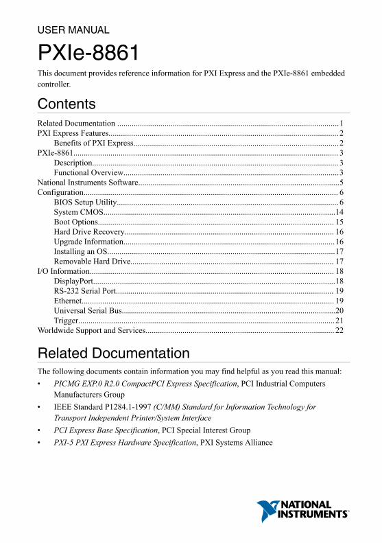
Functional OverviewThe PXIe-8861 is a modular PC in a PXI Express 3U-size form factor. The following figure isa functional block diagram of the PXIe-8861. Following the diagram is a description of eachlogic block shown.
PXIe-8861 User Manual | © National Instruments | 3
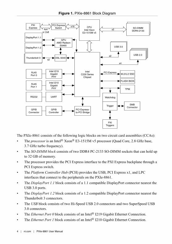
Figure 1. PXIe-8861 Block Diagram
IntelC230 Series
Chipset
CPUIntel Xeon
E3-1515M v5
SO-DIMMDDR4-2133
DisplayPort 1.1
x2
USB 2.0
M.2/U.2 SSD
FLASH BIOS
Watchdog
Trigger SMBConnector
TPM
x16
PXITriggers
x4
Intel I219Gigabit
PHY
RJ45Port 0
PCI Express
PCI ExpressSwitch
PXIExpress
4x4or 2x8
USB 3.0
x2
GPUAMD Radeon
E6465
Thunderbolt 3x2
DSL 6540
Intel I210Gigabit
PHY
RJ45Port 1
GPIBController
GPIBConnector
PCI Express-to-PCI Bridge
DisplayPort 1.2
RS232 UART
The PXIe-8861 consists of the following logic blocks on two circuit card assemblies (CCAs):• The processor is an Intel® Xeon® E3-1515M v5 processor (Quad Core, 2.8 GHz base,
3.7 GHz turbo frequency).• The SO-DIMM block consists of two DDR4 PC-2133 SO-DIMM sockets that can hold up
to 32 GB of memory.• The processor provides the PCI Express interface to the PXI Express backplane through a
PCI Express switch.• The Platform Controller Hub (PCH) provides the USB, PCI Express x1, and LPC
interfaces that connect to the peripherals on the PXIe-8861.• The DisplayPort 1.1 block consists of a 1.1 compatible DisplayPort connector nearest the
USB 3.0 ports.• The DisplayPort 1.2 block consists of a 1.2 compatible DisplayPort connector nearest the
Thunderbolt 3 connectors.• The USB block consists of two Hi-Speed USB 2.0 connectors and two SuperSpeed USB
3.0 connectors.• The Ethernet Port 0 block consists of an Intel® I219 Gigabit Ethernet Connection.• The Ethernet Port 1 block consists of an Intel® I210 Gigabit Ethernet Connection.
4 | ni.com | PXIe-8861 User Manual
• The UART block connects to one serial port.• The SMB Front Panel Trigger provides a routable connection of the PXI triggers to/from
the SMB on the front panel.• The Watchdog block consists of a watchdog timer that can reset the controller or generate
triggers.• The PXI Express Connectors connect the PXIe-8861 to the PXI Express/CompactPCI
Express backplane.
National Instruments SoftwareNational Instruments has developed several software tools you can use with the PXIe-8861.
National Instruments hardware and software work together to help you make the most of yourPXI system. The LabVIEW, Measurement Studio, and LabWindows™/CVI™ applicationdevelopment environments combine with leading hardware drivers such as NI-DAQmx toprovide exceptional control of NI hardware. Instrument drivers are available at ni.com/idnet to simplify communication with instruments over a variety of buses.
LabVIEW is a powerful and easy-to-use graphical programming environment you can use toacquire data from thousands of different instruments including USB, IEEE 488.2, VXI, serial,PLCs, and plug-in boards. LabVIEW helps you convert acquired data into meaningful resultsusing powerful data analysis routines. Add-on tools provide additional specializedfunctionality. For more information, visit ni.com/labview and ni.com/toolkits.
If you prefer to use Microsoft’s Visual Basic, Visual C++, and Visual Studio .NET for the coreof your application, Measurement Studio adds tools for Measurement and Automation to eachlanguage. For more information, visit ni.com/mstudio.
LabWindows/CVI is an interactive ANSI C programming environment designed for buildingvirtual instrument applications. LabWindows/CVI delivers a drag-and-drop editor for buildinguser interfaces, a complete ANSI C environment for building your test program logic, and acollection of automated code generation tools, as well as utilities for building automated testsystems, monitoring applications, or laboratory experiments. For more information, visitni.com/lwcvi.
NI-DAQmx provides an extensive library of functions that you can call from your applicationdevelopment environment or interactive environment such as NI Signal Express. Thesefunctions provide an intuitive API for National Instruments multifunction DAQ products.Features available include analog input (A/D conversion), buffered data acquisition (high-speed A/D conversion), analog output (D/A conversion), waveform generation, digital I/O,counter/timer operations, SCXI signal conditioning, RTSI or PXI synchronization, self-calibration, messaging, and acquiring data to extended memory. For more information, visitni.com/daq.
PXIe-8861 User Manual | © National Instruments | 5
National Instruments modular instruments use specialized drivers suited to each product’sspecialization. Express VIs provide customized, interactive programming of instruments in asingle interface, and soft front panels provide an interface for testing the functionality of eachinstrument with no programming required. NI Switches, DMMs, High-Speed DIO, High-Speed Digitizers, and Sources each have customized drivers for high-end modularinstrumentation systems. RF applications leverage two drivers, NI-RFSG and NI-RFSA, andDynamic Signal Acquisition is available through NI-DAQmx. For more information, visitni.com/modularinstruments.
You can expand the timing and triggering functionality of your PXI system with PXI Timingand Synchronization products. These products provide precision clock sources, custom routingof triggers for multi-chassis synchronization, clock sharing, and more and are programmedwith NI-Sync. For more information, visit ni.com/pxi.
NI-VISA is the National Instruments implementation of the VISA specification. VISA is auniform API for communicating and controlling USB, Serial, GPIB, PXI, VXI, and variousother types of instruments. This API aids in the creation of portable applications andinstrument drivers. For information about writing your own PXI instrument driver withNI-VISA, refer to the NI-VISA Getting Started Manual and the readme.txt file in theNI-VISA directory. For more information, visit ni.com/visa.
With LabVIEW for Linux and support for more than two hundred devices on Linux with theNI-DAQmx driver, you can now create virtual instruments based on the Linux OS. Instrumentcontrol in Linux has been improved by the NI-VISA driver for Linux, and NI modularinstruments are partially supported. For more information, visit ni.com/linux.
Configuration
BIOS Setup UtilityYou can change the PXIe-8861 configuration settings in the BIOS setup program. The BIOS isthe low-level interface between the hardware and operating system software that configuresand tests your hardware when you boot the system. The BIOS setup program includes menusfor configuring settings and enabling PXIe-8861 controller features.
Most users do not need to use the BIOS setup program, as the PXIe-8861 controller ships withdefault settings that work well for most configurations.
Caution Changing BIOS settings may lead to incorrect controller behavior andpossibly an unbootable controller. If this happens, follow the instructions forrestoring default settings in the System CMOS section. In general, do not change asetting unless you are absolutely certain what it does.
6 | ni.com | PXIe-8861 User Manual
Accessing BIOS Setup Utility1. Power on or restart your PXIe-8861 controller.2. When the message Press <DEL> to enter setup appears, press the <Delete> key.
The setup program loads after a short delay.
The Main menu is displayed when you first enter the BIOS setup program.
Use the following keys to navigate through the BIOS setup program:• Left Arrow, Right Arrow—Use these keys to move between the different setup menus.
If you are in a submenu, these keys have no effect, and you must press <Esc> to leave thesubmenu first. (To use the arrows on the numeric keypad, you must turn off Num Lock.)
• Up Arrow, Down Arrow—Use these keys to move between the options within a setupmenu. (To use the arrows on the numeric keypad, you must turn off Num Lock.)
• <Enter>—Use this key either to enter a submenu or display all available settings for ahighlighted configuration option.
• <Esc>—Use this key to return to the parent menu of a submenu. At the top-level menus,this key serves as a shortcut to the Exit menu.
• <+> and <–>—Use these keys to cycle between all available settings for a selectedconfiguration option.
• <Tab>—Use this key to select time and date fields.• <F9>—Use this key to load the optimal default values for BIOS configuration settings.
The optimal default values are the same as the shipping configuration default values.
Main Setup MenuThe most commonly accessed and modified BIOS settings are in the Main setup menu. TheMain setup menu reports the following configuration information:• BIOS Version and Build Date—These values indicate the version of the PXIe-8861
controller BIOS and the date on which the BIOS was built.• Embedded Firmware Version—This value helps identify the built-in hardware
capabilities.• Processor Type, Base/Max Processor Frequency, and Active Processor Cores—These
values indicate the type of processor used in the PXIe-8861 controller, the processorspeed, and the maximum number of processor cores.
• Microcode Revision—This is the microcode revision of your PXIe-8861 processor.• Total Memory and Frequency—This value indicates the system RAM size and
frequency the BIOS detects.• PXIe Chassis Information—These values indicate the overall chassis link configuration,
the link width of each link, and the link speed of each link.
PXIe-8861 User Manual | © National Instruments | 7
The Main setup menu also includes the following settings:• System Date—This setting controls the date, which is stored in a battery-backed real-
time clock. Most operating systems also include a way to change this setting. Use <+>and <-> in conjunction with <Enter> and <Tab> to change these values.
• System Time—This setting controls the time of day, which is stored in a battery-backedreal-time clock. Most operating systems include a way to change this setting. Use <+>and <-> in conjunction with <Enter> and <Tab> to change these values.
Advanced Setup MenuThis menu contains BIOS settings that normally do not require modification. If you havespecific problems such as unbootable disks or resource conflicts, you may need to examinethese settings.
Caution Changing settings in this menu may result in an unstable or unbootablecontroller. If this happens, follow the procedures outlined in the System CMOSsection to restore BIOS settings to their factory defaults.
The Advanced setup menu includes the following settings and submenus:• CPU Configuration—Use this setting to access the CPU Configuration submenu. Refer
to the CPU Configuration Submenu section for more information.• Video Configuration—Use this setting to access the Video Configuration submenu.
Refer to the Video Configuration Submenu section for more information.• Power/Wake Configuration—Use this setting to access the Power/Wake
Configuration submenu. Refer to the Power/Wake Configuration Submenu section formore information.
• PCI Configuration—Use this setting to access the PCI Configuration submenu. Referto the PCI Configuration Submenu section for more information.
• AMT Configuration—Use this setting to access the AMT Configuration submenu.Refer to the AMT Configuration Submenu section for more information.
• USB Configuration—Use this setting to access the USB Configuration submenu. Referto the USB Configuration Submenu section for more information.
• Thunderbolt Configuration—Use this setting to access the ThunderboltConfiguration submenu. Refer to the Thunderbolt Configuration Submenu section formore information.
• TPM Configuration—Use this setting to access the TPM Configuration submenu.Refer to the TPM Configuration Submenu section for more information.
CPU Configuration SubmenuUse this submenu to apply alternate settings to the CPU. Normally, you do not need to modifythese settings, as the factory default settings provide the most compatible and optimalconfiguration possible.• Hyper Threading—This setting enables or disables Intel Hyper-Threading technology.
The default value is Enabled. Enabling Hyper-Threading increases performance for some
8 | ni.com | PXIe-8861 User Manual
applications by adding virtual CPU cores. Hyper-Threading can increase applicationjitter, so be careful when enabling this setting on a Real Time system. When the BIOS isconfigured to boot LabVIEW Real-Time, Hyper-Threading is disabled automatically.
• Enabled CPU Cores—This setting selects the number of active CPU cores for theprocessor. Valid values are 1, 2, 3, and All. The default value is All.
• C-States—This setting enables or disables CPU power management. The default value isEnabled. Enabling C-States allows the processor to put idle CPU cores to sleep, allowingactive cores to run at higher than base frequencies when Turbo Boost is enabled. EnablingC-States can increase application jitter, so be careful when enabling this setting on a RealTime system. When the BIOS is configured to boot LabVIEW Real-Time, C-States aredisabled automatically.
• Turbo Boost—This setting enables or disables Intel Turbo Boost technology. The defaultis Enabled. Enabling Turbo Boost allows CPU cores to run at higher than their basefrequency for short durations, while other cores are idle. Enabling Turbo Boost can alsoincrease application jitter, so be careful when enabling this setting on a LabVIEW Real-Time system. To achieve maximum possible Turbo Boost frequencies, also enable the C-States setting.
Video Configuration SubmenuUse this submenu to apply alternate settings to the video configuration. Normally, you do notneed to modify these settings, as the factory default settings provide the most compatible andoptimal configuration possible.• Primary Display—This setting specifies which video adapter the BIOS should use as the
primary adapter if more than one is present. To use an external video adapter as theprimary graphics adapter, choose Offboard Video. The default value is Onboard AMDVideo.
Power/Wake Configuration SubmenuUse this submenu to apply alternate configurations to the power and wake features of thechipset and controller. Normally, you do not need to modify these settings, as the factorydefault settings provide the most compatible and optimal configuration possible.• Restore After Power Loss—This setting specifies the power state that the controller
should return to after AC power is lost. Valid values are Stay Off and Turn On. Thedefault is Stay Off. When set to Stay Off, the controller returns to the soft off power stateafter AC power is restored. When set to Turn On, the controller powers on when ACpower is restored.
• Power Button Off Behavior—This setting specifies how the PXI Express power buttonshould behave. Valid options are Enabled and Disabled. The default value is Enabled.When set to Enabled, the OS controls the power button. When set to Disabled, pressingthe power button has no effect. The Disabled option should be used only in conjunctionwith the PXI Express chassis’ inhibit mode switch.
PXIe-8861 User Manual | © National Instruments | 9
• PXIe Backplane WAKE#—This setting enables or disables a PXI Express peripheralmodule’s ability to wake a soft off system. The default value is Disabled.
• SMBus ALERT#—This setting enables or disables a System Management device’sability to wake a soft off system by asserting the ALERT# signal. The default value isDisabled.
PCI Configuration SubmenuUse this submenu to apply alternate settings to PCI devices. Normally, you do not need tomodify these settings, as the factory default settings provide the most compatible and optimalconfiguration possible.• 64-Bit Memory Mapped IO—This setting enables or disables support for memory-
mapped I/O above the 4 GB boundary. It can be useful when using a 64-bit OS and alarge number of PCI devices. The default value is Disabled.
• PCIe Max Payload Size—This setting determines the maximum payload size of PCIExpress devices. Valid options are Auto and 128 Bytes. The default value is Auto, whichallows the BIOS to choose an optimal value based on which devices are present.
• PCIe Max Read Request Size—This setting determines the maximum size of memoryread requests for PCI Express devices. Valid options range from 128 bytes to 4096 bytes.The default value is 4096 bytes, which allows the BIOS to choose an optimal value basedon which devices are present.
• PCI System Error Reporting—This setting enables/disables reporting of PCI systemerrors. The default value is Enabled.
USB Configuration SubmenuUse this submenu to apply alternate configurations to the USB ports. Normally, you do notneed to modify these settings, as the factory default settings provide the best possibleconfiguration.• USB Devices—This item lists the total number of devices detected in the system,
categorized by device type.• Legacy USB Support—This setting specifies whether legacy USB support is enabled.
Legacy USB support refers to the ability to use a USB keyboard and mouse duringsystem boot or in a legacy operating system such as DOS. The default value is Enabled.This option is disabled automatically when booting LabVIEW Real-Time to reduceapplication jitter.
• Overcurrent Reporting—This setting allows the BIOS to notify the operating system ofany USB ports which sources too much current. The default value for this setting isDisabled.
• Transfer Timeout—This setting specifies the timeout value for Control, Bulk, andInterrupt USB transfers. The default value for this setting is 20 seconds.
• Device Reset Timeout—This setting specifies the number of seconds the Power-On SelfTest waits for a USB mass storage device to start. The default is 20 seconds.
10 | ni.com | PXIe-8861 User Manual
• Device Power-Up Delay—This setting specifies the maximum time a device takes beforeit properly reports itself to the host controller. When set to Auto, a root port is granted100 ms, and for a hub port, the delay value is taken from the hub descriptor. When set toManual, you can set the delay manually. The default value for this setting is Auto.
• Device Power-Up Delay in Seconds—This setting specifies the number of seconds thePower-On Self Test waits for a USB device or hub to power on. This setting is visibleonly if Device Power-Up Delay is set to Manual. The default is 5 seconds.
In addition, the following option is available for each detected device if a USB mass storagedevice is present:• Emulation Type—This setting specifies how the BIOS presents the USB mass storage
device to the system. You can use this option to present a USB mass storage device as afloppy, Zip, hard disk, or CD-ROM drive. The default is Auto, which allows the BIOS totreat small USB flash disk drives as floppy drives and larger USB flash disk drives ashard disk drives.
Thunderbolt Configuration SubmenuUse this submenu to enable or disable Thunderbolt support and configure the Thunderboltsecurity level.• Thunderbolt Support—This option enables or disables Thunderbolt support. The
default value is Enabled.• Thunderbolt Security Level—Use this option to configure the Thunderbolt security
level. The default value is User Authorization.
TPM Configuration SubmenuUse this submenu to view the Trusted Platform Module (TPM) hardware type and executeselected TPM commands.• Clear TPM—Use this option to clear the TPM.
Caution Clearing the TPM is a destructive operation that may result in the loss ofall data protected by the TPM device.
TPM Physical Presence Confirmation ScreenSome TPM commands may require confirmation of physical presence before they can beexecuted. In this case, the system will reboot and the BIOS will present a screen asking forconfirmation to execute the TPM command. You can confirm or reject the execution of theTPM command.
PXIe-8861 User Manual | © National Instruments | 11
Boot Setup MenuUse this menu to configure settings related to the boot process and boot device priority.• Boot Settings Configuration—Use this setting to access the Boot Settings
Configuration submenu. Refer to the Boot Settings Configuration Submenu section formore information.
• PXI Drive Boot—This setting specifies whether boot support is enabled for legacy massstorage devices, such as SCSI drives. When enabled, legacy mass storage controllers withboot support are displayed in the Boot Option Priorities menu. The default value isEnabled.
• PXE Network Boot—This setting specifies whether the PXE network boot agent isenabled. When enabled, the Intel Boot Agent is displayed in the Boot Option Prioritiesmenu, allowing you to boot from a PXE server on the local subnet. Note that the IntelBoot Agent device names are preceded by IBA GE Slot in the Boot Option Prioritiesmenu. You must restart the system for this setting to take effect. The default value isDisabled.
• Boot Option Priorities—These settings specify the order in which the BIOS checks forbootable devices, including the local hard disk drive, removable devices such as USBflash disk drives or USB CD-ROM drives, or the PXE network boot agent. The BIOSfirst attempts to boot from the device associated with 1st Boot Device, followed by 2ndBoot Device, and 3rd Boot Device. If multiple boot devices are not present, the BIOSsetup utility does not display all these configuration options. To select a boot device,press <Enter> on the desired configuration option and select a boot device from theresulting menu. You also can disable certain boot devices by selecting Disabled.
Note Only one device of a given type is shown in this list. If more than one deviceof the same type exists, use the Device BBS Priorities submenus to re-order thepriority of devices of the same type.
The following submenus are displayed if one or more bootable devices of the correspondingtype is present:• Hard Drive BBS Priorities—Use this setting to access the Hard Drive BBS Priorities
submenu to re-order or disable bootable hard drive devices. Refer to the Hard Drive BBSPriorities Submenu section for more information.
• CD/DVD ROM Drive BBS Priorities—Use this setting to access the CD/DVD ROMDrive BBS Priorities submenu to re-order or disable bootable CD/DVD ROM drivedevices. Refer to the CD/DVD ROM Drive BBS Priorities Submenu section for moreinformation.
12 | ni.com | PXIe-8861 User Manual
• Floppy Drive BBS Priorities—Use this setting to access the Floppy Drive BBSPriorities submenu to re-order or disable bootable floppy drive devices. Refer to theFloppy Drive BBS Priorities Submenu section for more information.
• Network Device BBS Priorities—Use this setting to access the Network Device BBSPriorities submenu to re-order or disable bootable network devices. Refer to the NetworkDevice BBS Priorities Submenu section for more information.
Boot Settings Configuration SubmenuUse this submenu to apply alternate configurations to boot settings. Normally, you do not needto modify these settings, as the factory default settings provide the most compatible andoptimal configuration.• Setup Prompt Timeout—This setting specifies the number of seconds the system waits
for a BIOS Setup menu keypress (the <Delete> key). The default value is 2.• Bootup NumLock State—This setting specifies the power-on state of the keyboard
NumLock setting. The default value is On.
Hard Drive BBS Priorities Submenu• Boot Option #1, Boot Option #2, Boot Option #3—These settings specify the boot
priority of hard drive devices. The highest priority device is displayed on the main BootOption Priorities list. Optionally, each device can also be Disabled if the device shouldnever be used as a boot device.
CD/DVD ROM Drive BBS Priorities Submenu• Boot Option #1, Boot Option #2, Boot Option #3—These settings specify the boot
priority of CD/DVD ROM drive devices. The highest priority device is displayed on themain Boot Option Priorities list. Optionally, each device can also be Disabled if thedevice should never be used as a boot device.
Floppy Drive BBS Priorities Submenu• Boot Option #1, Boot Option #2, Boot Option #3—These settings specify the boot
priority of floppy drive devices. The highest priority device is displayed on the main BootOption Priorities list. Optionally, each device can also be Disabled if the device shouldnever be used as a boot device.
Network Device BBS Priorities Submenu• Boot Option #1, Boot Option #2, Boot Option #3—These settings specify the boot
priority of network devices. The highest priority device is displayed on the main BootOption Priorities list. Optionally, each device can also be Disabled if the device shouldnever be used as a boot device.
PXIe-8861 User Manual | © National Instruments | 13
Security MenuUse this menu to enable BIOS security options.• Administrator Password—This setting specifies a password that must be entered to
access the BIOS Setup Utility. If only the Administrator’s password is set, this settinglimits access to only the BIOS setup program and is asked for only when entering theBIOS setup program. By default, no password is specified.
• User Password—This setting specifies a password that must be entered to access theBIOS Setup Utility or boot the system. If only the user’s password is set, this is a poweron password and must be entered to boot or enter the BIOS setup program. In the BIOSsetup program, the user has Administrator rights. By default, no password is specified.
Save & Exit MenuThe Save & Exit setup menu includes all available options for exiting, saving, and loading theBIOS default configuration. As an alternative to this screen, press <F9> to load optimal BIOSdefault settings and <F10> to save changes and exit setup.
The Save & Exit setup menu includes the following settings:• Save Changes and Reset—Any changes made to BIOS settings are stored in NVRAM.
The setup program then exits and reboots the controller. You also can use the <F10> keyto select this option.
• Discard Changes—Any changes made to BIOS settings during this session of the BIOSsetup program are discarded. The BIOS setup continues to be active.
• Restore Factory Defaults—This option restores all BIOS settings to the factory default.This option is useful if the controller exhibits unpredictable behavior due to an incorrector inappropriate BIOS setting. Notice that any nondefault settings such as boot order,passwords, and so on also are restored to their factory defaults. You also can use the <F9>key to select this option.
• Save As User Defaults—This option saves a copy of the current BIOS settings as theUser Defaults. This option is useful for preserving custom BIOS setup configurations.
• Restore User Defaults—This option restores all BIOS settings to the user defaults. Thisoption is useful for restoring previously preserved custom BIOS setup configurations.
• Boot Override—This option lists all possible bootable devices and allows the user tooverride the Boot Option Priorities list for the current boot. If no changes have beenmade to the BIOS setup options, the system continues booting to the selected devicewithout first rebooting. If BIOS setup options have been changed and saved, a reboot isrequired and the boot override selection is not valid.
System CMOSThe PXIe-8861 contains memory backed up by a battery to store BIOS configurationinformation.
14 | ni.com | PXIe-8861 User Manual
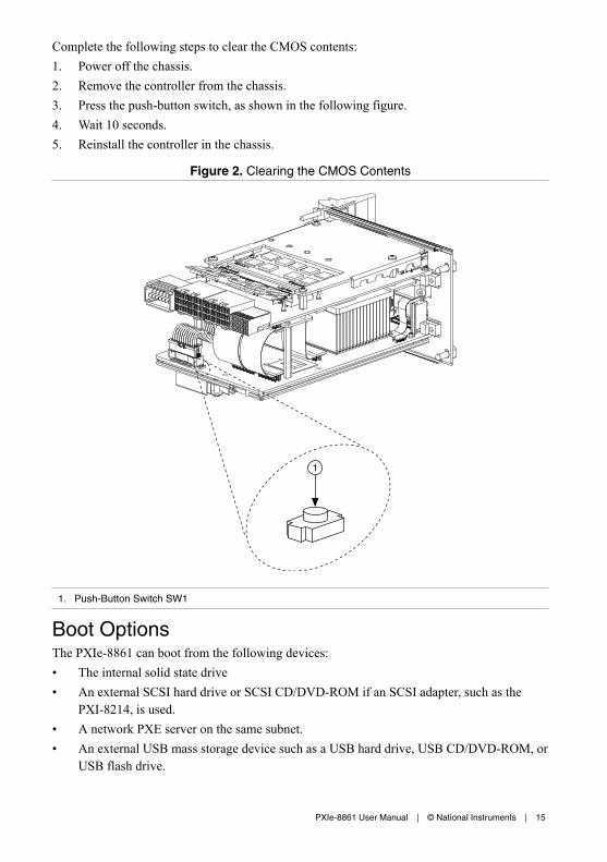
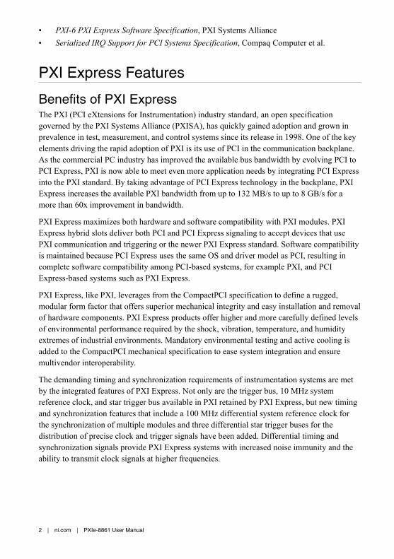
Complete the following steps to clear the CMOS contents:1. Power off the chassis.2. Remove the controller from the chassis.3. Press the push-button switch, as shown in the following figure.4. Wait 10 seconds.5. Reinstall the controller in the chassis.
Figure 2. Clearing the CMOS Contents
1
1. Push-Button Switch SW1
Boot OptionsThe PXIe-8861 can boot from the following devices:• The internal solid state drive• An external SCSI hard drive or SCSI CD/DVD-ROM if an SCSI adapter, such as the
PXI-8214, is used.• A network PXE server on the same subnet.• An external USB mass storage device such as a USB hard drive, USB CD/DVD-ROM, or
USB flash drive.
PXIe-8861 User Manual | © National Instruments | 15
• An external USB floppy drive.• Most PCI or PCI Express-based devices that provide an Option ROM.
There are two ways to configure the controller to boot from these devices:• Enter the BIOS setup by rebooting the controller and pressing <Delete> during the
memory tests. Select the Boot menu. You will see a list of all bootable devices, orderedby device type. You can set the boot order by altering the 1st Boot Device, 2nd BootDevice, and 3rd Boot Device settings.
• To boot from a different device without permanently changing the boot order, press<F10> during POST. After the BIOS completes the POST and just before the controllerboots the OS, the Boot menu is displayed. You can select the device type you want toboot from.
Hard Drive RecoveryPXIe-8861 controllers preinstalled with Windows include two methods of restoring theoriginal factory condition of your drive. Solid state drive-based recovery stores a factorybackup on a separate portion of your drive, allowing you to restore your controller withoutadditional media. You also can recover the system using external recovery media created byNI (p/n 502202A-00) or by using Windows Recovery tools.
Note The drive recovery hot key is <1>. To access the drive-based recovery tool,press and hold <1> when video first appears during the boot process.
Note Recovering the OS erases the contents of your hard disk. Back up any filesyou want to keep.
Upgrade InformationYou can change the amount of installed RAM on the PXIe-8861.
National Instruments offers the following SO-DIMMs for use with the PXIe-8861 controller.• 8 GB DDR4-2133 compatible SO-DIMM (NI part number 786777-01)• 16 GB DDR4-2133 compatible SO-DIMM (NI Part number 786776-01)
Note National Instruments has tested and verified that the SO-DIMMs we sellwork with the PXIe-8861 controller. We recommend you purchase your SO-DIMMmodules from National Instruments. Other off-the-shelf SO-DIMM modules are notguaranteed to work properly.
16 | ni.com | PXIe-8861 User Manual
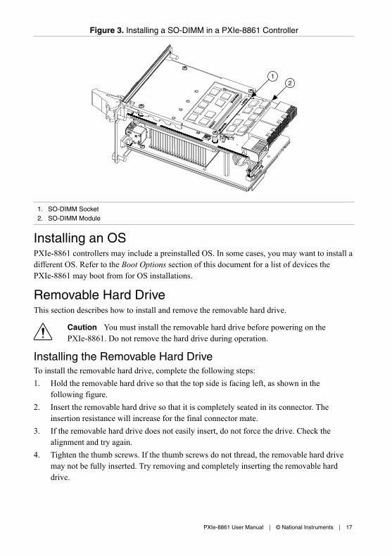
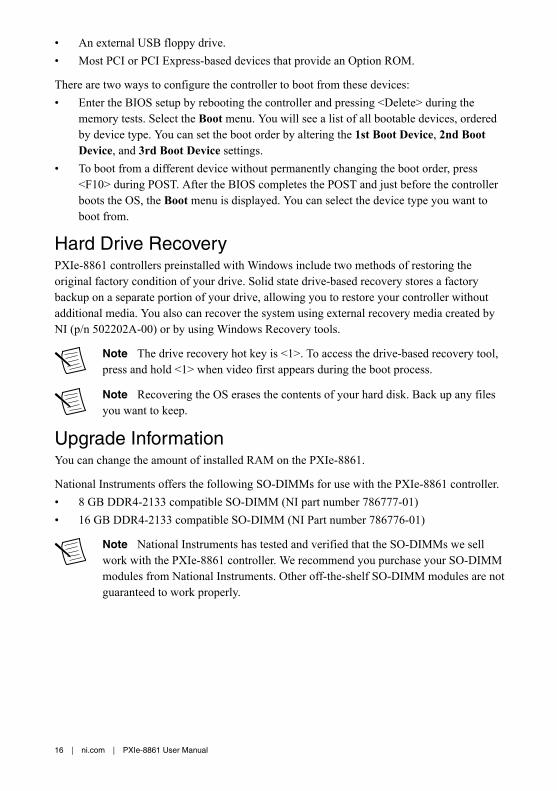
Figure 3. Installing a SO-DIMM in a PXIe-8861 Controller
21
1. SO-DIMM Socket2. SO-DIMM Module
Installing an OSPXIe-8861 controllers may include a preinstalled OS. In some cases, you may want to install adifferent OS. Refer to the Boot Options section of this document for a list of devices thePXIe-8861 may boot from for OS installations.
Removable Hard DriveThis section describes how to install and remove the removable hard drive.
Caution You must install the removable hard drive before powering on thePXIe-8861. Do not remove the hard drive during operation.
Installing the Removable Hard DriveTo install the removable hard drive, complete the following steps:1. Hold the removable hard drive so that the top side is facing left, as shown in the
following figure.2. Insert the removable hard drive so that it is completely seated in its connector. The
insertion resistance will increase for the final connector mate.3. If the removable hard drive does not easily insert, do not force the drive. Check the
alignment and try again.4. Tighten the thumb screws. If the thumb screws do not thread, the removable hard drive
may not be fully inserted. Try removing and completely inserting the removable harddrive.
PXIe-8861 User Manual | © National Instruments | 17
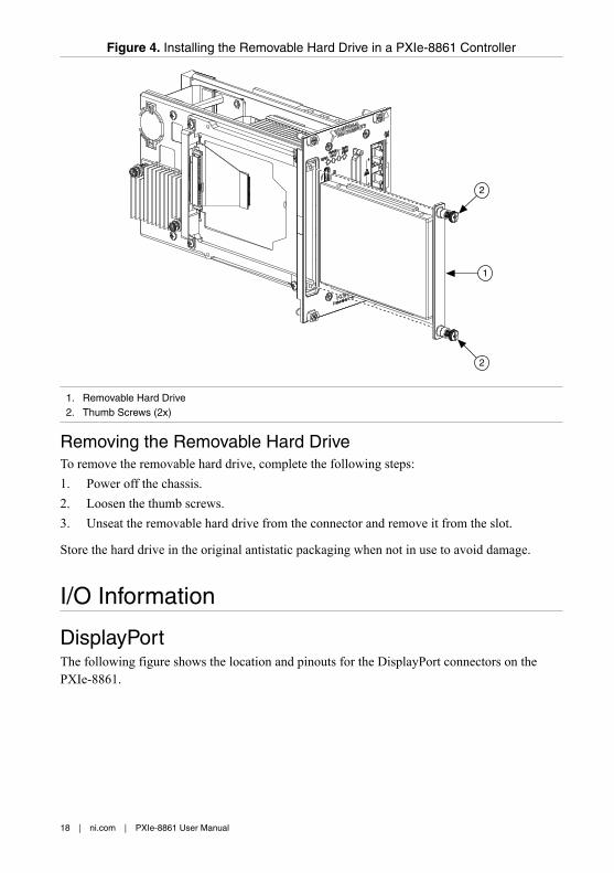
Figure 4. Installing the Removable Hard Drive in a PXIe-8861 Controller
1
2
2
1. Removable Hard Drive2. Thumb Screws (2x)
Removing the Removable Hard DriveTo remove the removable hard drive, complete the following steps:1. Power off the chassis.2. Loosen the thumb screws.3. Unseat the removable hard drive from the connector and remove it from the slot.
Store the hard drive in the original antistatic packaging when not in use to avoid damage.
I/O Information
DisplayPortThe following figure shows the location and pinouts for the DisplayPort connectors on thePXIe-8861.
18 | ni.com | PXIe-8861 User Manual
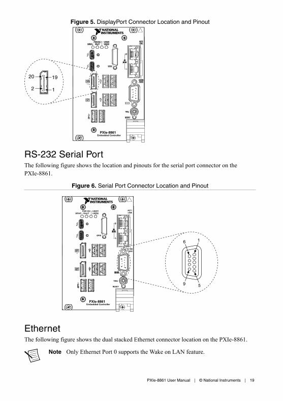
Figure 5. DisplayPort Connector Location and Pinout
1
1920
2
PXIe-8861Embedded Controller
1.2
RS-232 Serial PortThe following figure shows the location and pinouts for the serial port connector on thePXIe-8861.
Figure 6. Serial Port Connector Location and Pinout
PXIe-8861Embedded Controller
TRIG
RESET
GPIB
DRIVEPWR OK/
FAULTUSER1USER2
ACT/LINK
Pu
lse
10/100/1000
5
16
9
1.2
EthernetThe following figure shows the dual stacked Ethernet connector location on the PXIe-8861.
Note Only Ethernet Port 0 supports the Wake on LAN feature.
PXIe-8861 User Manual | © National Instruments | 19
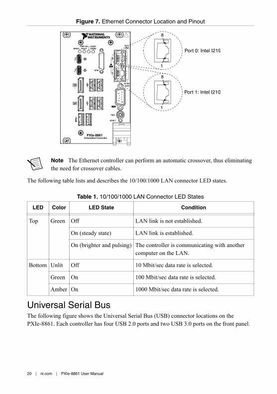
Figure 7. Ethernet Connector Location and Pinout
1
8
1
8
Port 0: Intel I219
Port 1: Intel I210
PXIe-8861Embedded Controller
TRIG
RESET
GPIB
DRIVEPWR OK/
FAULTUSER1USER2
ACT/LINK
Pu
lse
10/100/1000
1.2
Note The Ethernet controller can perform an automatic crossover, thus eliminatingthe need for crossover cables.
The following table lists and describes the 10/100/1000 LAN connector LED states.
Table 1. 10/100/1000 LAN Connector LED States
LED Color LED State Condition
Top Green Off LAN link is not established.
On (steady state) LAN link is established.
On (brighter and pulsing) The controller is communicating with anothercomputer on the LAN.
Bottom Unlit Off 10 Mbit/sec data rate is selected.
Green On 100 Mbit/sec data rate is selected.
Amber On 1000 Mbit/sec data rate is selected.
Universal Serial BusThe following figure shows the Universal Serial Bus (USB) connector locations on thePXIe-8861. Each controller has four USB 2.0 ports and two USB 3.0 ports on the front panel.
20 | ni.com | PXIe-8861 User Manual
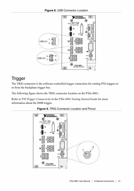
Figure 8. USB Connector Location
PXIe-8861Embedded Controller
TRIG
RESET
GPIB
DRIVEPWR OK/
FAULTUSER1USER2
ACT/LINK
Pu
lse
10/100/1000USB 2.0
4
1
9
54
1USB 3.0
1.2
TriggerThe TRIG connector is the software-controlled trigger connection for routing PXI triggers toor from the backplane trigger bus.
The following figure shows the TRIG connector location on the PXIe-8861.
Refer to PXI Trigger Connectivity in the PXIe-8861 Getting Started Guide for moreinformation about the SMB trigger.
Figure 9. TRIG Connector Location and Pinout
PXIe-8861Embedded Controller
TRIG
RESET
GPIB
DRIVEPWR OK/
FAULTUSER1USER2
ACT/LINK
Pu
lse
10/100/1000
12
1.2
PXIe-8861 User Manual | © National Instruments | 21
Worldwide Support and ServicesThe NI website is your complete resource for technical support. At ni.com/support, you haveaccess to everything from troubleshooting and application development self-help resources toemail and phone assistance from NI Application Engineers.
Visit ni.com/services for information about the services NI offers.
Visit ni.com/register to register your NI product. Product registration facilitates technicalsupport and ensures that you receive important information updates from NI.
NI corporate headquarters is located at 11500 North Mopac Expressway, Austin, Texas,78759-3504. NI also has offices located around the world. For support in the United States,create your service request at ni.com/support or dial 1 866 ASK MYNI (275 6964). Forsupport outside the United States, visit the Worldwide Offices section of ni.com/niglobal toaccess the branch office websites, which provide up-to-date contact information.
Information is subject to change without notice. Refer to the NI Trademarks and Logo Guidelines at ni.com/trademarks forinformation on NI trademarks. Other product and company names mentioned herein are trademarks or trade names of theirrespective companies. For patents covering NI products/technology, refer to the appropriate location: Help»Patents in yoursoftware, the patents.txt file on your media, or the National Instruments Patent Notice at ni.com/patents. You can findinformation about end-user license agreements (EULAs) and third-party legal notices in the readme file for your NI product. Referto the Export Compliance Information at ni.com/legal/export-compliance for the NI global trade compliance policy and howto obtain relevant HTS codes, ECCNs, and other import/export data. NI MAKES NO EXPRESS OR IMPLIED WARRANTIES ASTO THE ACCURACY OF THE INFORMATION CONTAINED HEREIN AND SHALL NOT BE LIABLE FOR ANY ERRORS. U.S.Government Customers: The data contained in this manual was developed at private expense and is subject to the applicablelimited rights and restricted data rights as set forth in FAR 52.227-14, DFAR 252.227-7014, and DFAR 252.227-7015.
© 2018—2019 National Instruments. All rights reserved.
377575C-01 July 18, 2019