Embed Size (px)
Citation preview

8545-M838-O1 825 Installation Page 1
825 WEIGHT INDICATOR
INSTALLATION and TECHNICAL MANUAL
8545-M838-O1 Rev A PO BOX 151 WEBB CITY, MO 64870 Printed in USA11/08 PH (417) 673-4631 FAX (417) 673-5001 www.cardinalscale.com
Technical Support: Ph: 866-254-8261 [email protected]

8545-M838-O1 825 Installation Page 2
8545-M838-O1 825 Installation Page 3
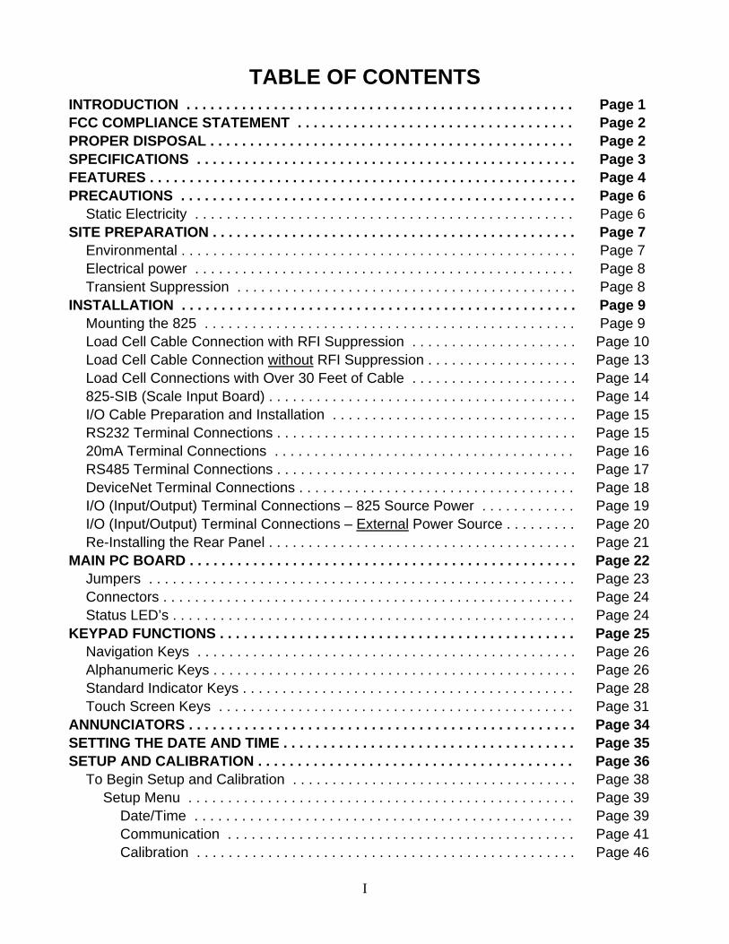
TABLE OF CONTENTS INTRODUCTION . . . . . . . . . . . . . . . . . . . . . . . . . . . . . . . . . . . . . . . . . . . . . . . . . Page 1 FCC COMPLIANCE STATEMENT . . . . . . . . . . . . . . . . . . . . . . . . . . . . . . . . . . . Page 2 PROPER DISPOSAL . . . . . . . . . . . . . . . . . . . . . . . . . . . . . . . . . . . . . . . . . . . . . . Page 2 SPECIFICATIONS . . . . . . . . . . . . . . . . . . . . . . . . . . . . . . . . . . . . . . . . . . . . . . . . Page 3 FEATURES . . . . . . . . . . . . . . . . . . . . . . . . . . . . . . . . . . . . . . . . . . . . . . . . . . . . . . Page 4 PRECAUTIONS . . . . . . . . . . . . . . . . . . . . . . . . . . . . . . . . . . . . . . . . . . . . . . . . . . Page 6
Static Electricity . . . . . . . . . . . . . . . . . . . . . . . . . . . . . . . . . . . . . . . . . . . . . . . . Page 6 SITE PREPARATION . . . . . . . . . . . . . . . . . . . . . . . . . . . . . . . . . . . . . . . . . . . . . . Page 7
Environmental . . . . . . . . . . . . . . . . . . . . . . . . . . . . . . . . . . . . . . . . . . . . . . . . . . Page 7 Electrical power . . . . . . . . . . . . . . . . . . . . . . . . . . . . . . . . . . . . . . . . . . . . . . . . Page 8 Transient Suppression . . . . . . . . . . . . . . . . . . . . . . . . . . . . . . . . . . . . . . . . . . . Page 8
INSTALLATION . . . . . . . . . . . . . . . . . . . . . . . . . . . . . . . . . . . . . . . . . . . . . . . . . . Page 9 Mounting the 825 . . . . . . . . . . . . . . . . . . . . . . . . . . . . . . . . . . . . . . . . . . . . . . . Page 9 Load Cell Cable Connection with RFI Suppression . . . . . . . . . . . . . . . . . . . . . Page 10 Load Cell Cable Connection without RFI Suppression . . . . . . . . . . . . . . . . . . . Page 13 Load Cell Connections with Over 30 Feet of Cable . . . . . . . . . . . . . . . . . . . . . Page 14 825-SIB (Scale Input Board) . . . . . . . . . . . . . . . . . . . . . . . . . . . . . . . . . . . . . . . Page 14 I/O Cable Preparation and Installation . . . . . . . . . . . . . . . . . . . . . . . . . . . . . . . Page 15 RS232 Terminal Connections . . . . . . . . . . . . . . . . . . . . . . . . . . . . . . . . . . . . . . Page 15 20mA Terminal Connections . . . . . . . . . . . . . . . . . . . . . . . . . . . . . . . . . . . . . . Page 16 RS485 Terminal Connections . . . . . . . . . . . . . . . . . . . . . . . . . . . . . . . . . . . . . . Page 17 DeviceNet Terminal Connections . . . . . . . . . . . . . . . . . . . . . . . . . . . . . . . . . . . Page 18 I/O (Input/Output) Terminal Connections – 825 Source Power . . . . . . . . . . . . Page 19 I/O (Input/Output) Terminal Connections – External Power Source . . . . . . . . . Page 20 Re-Installing the Rear Panel . . . . . . . . . . . . . . . . . . . . . . . . . . . . . . . . . . . . . . . Page 21
MAIN PC BOARD . . . . . . . . . . . . . . . . . . . . . . . . . . . . . . . . . . . . . . . . . . . . . . . . . Page 22 Jumpers . . . . . . . . . . . . . . . . . . . . . . . . . . . . . . . . . . . . . . . . . . . . . . . . . . . . . . Page 23 Connectors . . . . . . . . . . . . . . . . . . . . . . . . . . . . . . . . . . . . . . . . . . . . . . . . . . . . Page 24 Status LED’s . . . . . . . . . . . . . . . . . . . . . . . . . . . . . . . . . . . . . . . . . . . . . . . . . . . Page 24
KEYPAD FUNCTIONS . . . . . . . . . . . . . . . . . . . . . . . . . . . . . . . . . . . . . . . . . . . . . Page 25 Navigation Keys . . . . . . . . . . . . . . . . . . . . . . . . . . . . . . . . . . . . . . . . . . . . . . . . Page 26 Alphanumeric Keys . . . . . . . . . . . . . . . . . . . . . . . . . . . . . . . . . . . . . . . . . . . . . . Page 26 Standard Indicator Keys . . . . . . . . . . . . . . . . . . . . . . . . . . . . . . . . . . . . . . . . . . Page 28 Touch Screen Keys . . . . . . . . . . . . . . . . . . . . . . . . . . . . . . . . . . . . . . . . . . . . . Page 31
ANNUNCIATORS . . . . . . . . . . . . . . . . . . . . . . . . . . . . . . . . . . . . . . . . . . . . . . . . . Page 34 SETTING THE DATE AND TIME . . . . . . . . . . . . . . . . . . . . . . . . . . . . . . . . . . . . . Page 35 SETUP AND CALIBRATION . . . . . . . . . . . . . . . . . . . . . . . . . . . . . . . . . . . . . . . . Page 36
To Begin Setup and Calibration . . . . . . . . . . . . . . . . . . . . . . . . . . . . . . . . . . . . Page 38 Setup Menu . . . . . . . . . . . . . . . . . . . . . . . . . . . . . . . . . . . . . . . . . . . . . . . . . Page 39
Date/Time . . . . . . . . . . . . . . . . . . . . . . . . . . . . . . . . . . . . . . . . . . . . . . . . Page 39 Communication . . . . . . . . . . . . . . . . . . . . . . . . . . . . . . . . . . . . . . . . . . . . Page 41 Calibration . . . . . . . . . . . . . . . . . . . . . . . . . . . . . . . . . . . . . . . . . . . . . . . . Page 46
I

8545-M838-O1 825 Installation Page 4
TABLE OF CONTENTS, CONT. PREFERENCES . . . . . . . . . . . . . . . . . . . . . . . . . . . . . . . . . . . . . . . . . . . . . . . . . . Page 62
Date/Time . . . . . . . . . . . . . . . . . . . . . . . . . . . . . . . . . . . . . . . . . . . . . . . . . . . . . Page 62 Sound Settings . . . . . . . . . . . . . . . . . . . . . . . . . . . . . . . . . . . . . . . . . . . . . . . . . Page 65
OPERATORS . . . . . . . . . . . . . . . . . . . . . . . . . . . . . . . . . . . . . . . . . . . . . . . . . . . . Page 66 List Operators . . . . . . . . . . . . . . . . . . . . . . . . . . . . . . . . . . . . . . . . . . . . . . . . . . Page 66 Add Operators . . . . . . . . . . . . . . . . . . . . . . . . . . . . . . . . . . . . . . . . . . . . . . . . . Page 67 Edit Operators . . . . . . . . . . . . . . . . . . . . . . . . . . . . . . . . . . . . . . . . . . . . . . . . . Page 69 Delete Operators . . . . . . . . . . . . . . . . . . . . . . . . . . . . . . . . . . . . . . . . . . . . . . . Page 72 Set Default Operators . . . . . . . . . . . . . . . . . . . . . . . . . . . . . . . . . . . . . . . . . . . . Page 73
CONFIGURATION . . . . . . . . . . . . . . . . . . . . . . . . . . . . . . . . . . . . . . . . . . . . . . . . Page 74 To Begin Configuration . . . . . . . . . . . . . . . . . . . . . . . . . . . . . . . . . . . . . . . . . . . Page 74
Calibration Touch Screen . . . . . . . . . . . . . . . . . . . . . . . . . . . . . . . . . . . . . . . Page 75 Show Touch Screen Tracking . . . . . . . . . . . . . . . . . . . . . . . . . . . . . . . . . . . Page 76 Set Color Setting . . . . . . . . . . . . . . . . . . . . . . . . . . . . . . . . . . . . . . . . . . . . . Page 77 Configure Weight Server . . . . . . . . . . . . . . . . . . . . . . . . . . . . . . . . . . . . . . . Page 78
Configure TCP/IP Server . . . . . . . . . . . . . . . . . . . . . . . . . . . . . . . . . . . . . Page 78 Configure Serial Ports . . . . . . . . . . . . . . . . . . . . . . . . . . . . . . . . . . . . . . . Page 81
Configuration of Weight Server Complete . . . . . . . . . . . . . . . . . . . . . . . . . . Page 83 TICKET SETTINGS . . . . . . . . . . . . . . . . . . . . . . . . . . . . . . . . . . . . . . . . . . . . . . . Page 84
Configure Ticket . . . . . . . . . . . . . . . . . . . . . . . . . . . . . . . . . . . . . . . . . . . . . . . . Page 84 Default Ticket Item Locations . . . . . . . . . . . . . . . . . . . . . . . . . . . . . . . . . . . . Page 85
Print Tab Setting . . . . . . . . . . . . . . . . . . . . . . . . . . . . . . . . . . . . . . . . . . . . . . . . Page 86 Configure Tabs Page 1 . . . . . . . . . . . . . . . . . . . . . . . . . . . . . . . . . . . . . . . . Page 86 Configure Tabs Page 2 . . . . . . . . . . . . . . . . . . . . . . . . . . . . . . . . . . . . . . . . Page 87 Configure Tabs Page 3 . . . . . . . . . . . . . . . . . . . . . . . . . . . . . . . . . . . . . . . . Page 88
CONFIGURE APPLICATION MENU . . . . . . . . . . . . . . . . . . . . . . . . . . . . . . . . . . Page 89 Enable/Disable Menu Items. . . . . . . . . . . . . . . . . . . . . . . . . . . . . . . . . . . . . . . . Page 89
APPLICATION MENU SCREEN . . . . . . . . . . . . . . . . . . . . . . . . . . . . . . . . . . . . . Page 92
II
8545-M838-O1 825 Installation Page 5
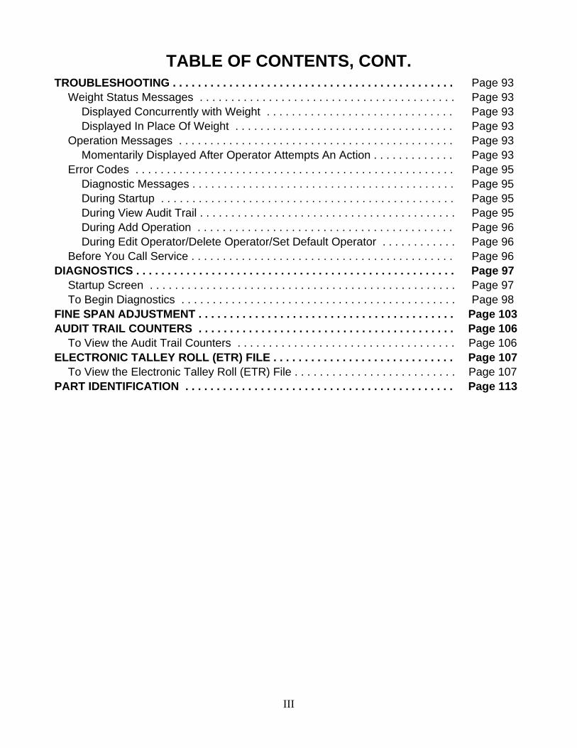
TABLE OF CONTENTS, CONT. TROUBLESHOOTING . . . . . . . . . . . . . . . . . . . . . . . . . . . . . . . . . . . . . . . . . . . . . Page 93
Weight Status Messages . . . . . . . . . . . . . . . . . . . . . . . . . . . . . . . . . . . . . . . . . Page 93 Displayed Concurrently with Weight . . . . . . . . . . . . . . . . . . . . . . . . . . . . . . Page 93 Displayed In Place Of Weight . . . . . . . . . . . . . . . . . . . . . . . . . . . . . . . . . . . Page 93
Operation Messages . . . . . . . . . . . . . . . . . . . . . . . . . . . . . . . . . . . . . . . . . . . . Page 93 Momentarily Displayed After Operator Attempts An Action . . . . . . . . . . . . . Page 93
Error Codes . . . . . . . . . . . . . . . . . . . . . . . . . . . . . . . . . . . . . . . . . . . . . . . . . . . Page 95 Diagnostic Messages . . . . . . . . . . . . . . . . . . . . . . . . . . . . . . . . . . . . . . . . . . Page 95 During Startup . . . . . . . . . . . . . . . . . . . . . . . . . . . . . . . . . . . . . . . . . . . . . . . Page 95 During View Audit Trail . . . . . . . . . . . . . . . . . . . . . . . . . . . . . . . . . . . . . . . . . Page 95 During Add Operation . . . . . . . . . . . . . . . . . . . . . . . . . . . . . . . . . . . . . . . . . Page 96 During Edit Operator/Delete Operator/Set Default Operator . . . . . . . . . . . . Page 96
Before You Call Service . . . . . . . . . . . . . . . . . . . . . . . . . . . . . . . . . . . . . . . . . . Page 96 DIAGNOSTICS . . . . . . . . . . . . . . . . . . . . . . . . . . . . . . . . . . . . . . . . . . . . . . . . . . . Page 97
Startup Screen . . . . . . . . . . . . . . . . . . . . . . . . . . . . . . . . . . . . . . . . . . . . . . . . . Page 97 To Begin Diagnostics . . . . . . . . . . . . . . . . . . . . . . . . . . . . . . . . . . . . . . . . . . . . Page 98
FINE SPAN ADJUSTMENT . . . . . . . . . . . . . . . . . . . . . . . . . . . . . . . . . . . . . . . . . Page 103 AUDIT TRAIL COUNTERS . . . . . . . . . . . . . . . . . . . . . . . . . . . . . . . . . . . . . . . . . Page 106
To View the Audit Trail Counters . . . . . . . . . . . . . . . . . . . . . . . . . . . . . . . . . . . Page 106 ELECTRONIC TALLEY ROLL (ETR) FILE . . . . . . . . . . . . . . . . . . . . . . . . . . . . . Page 107
To View the Electronic Talley Roll (ETR) File . . . . . . . . . . . . . . . . . . . . . . . . . . Page 107 PART IDENTIFICATION . . . . . . . . . . . . . . . . . . . . . . . . . . . . . . . . . . . . . . . . . . . Page 113
III

8545-M838-O1 825 Installation Page 6
IV
This page intentionally left blank.

8545-M838-O1 825 Installation & Technical Page 1
INTRODUCTION Thank you for selecting and purchasing the Cardinal Model 825 Weight Indicator. The Model 825 indicator was built with quality and reliability at our factory in Webb City, MO USA and incorporates the latest in digital technology and innovative features for the weighing industry. Configuration and upgrades can easily be performed in the field, while still maintaining the rigid control the most demanding installations require. This flexibility insures the Model 825 will be able to meet your weight indicating needs for years to come.
The purpose of this manual is to provide you with a guide through installation, setup and calibration of your new Model 825 Weight Indicator. Please read it thoroughly before attempting to install your indicator and keep it handy for future reference.
SERIAL NUMBER _____________________
DATE OF PURCHASE _________________
PURCHASED FROM __________________
____________________________________
____________________________________
____________________________________
RETAIN THIS INFORMATION FOR FUTURE USE
PRECAUTIONS Before using this instrument, read this manual and pay special attention to all "WARNING" symbols:
IMPORTANT
ELECTRICALWARNING
STATIC SENSITVE

8545-M838-O1 825 Installation & Technical Page 2
FCC COMPLIANCE STATEMENT WARNING! This equipment generates, uses and can radiate radio frequency and if not installed and used in accordance with the instruction manual, may cause interference to radio communications. It has been tested and found to comply with the limits for a Class A computing device pursuant to Subpart J of Part 15 of FCC rules, which are designed to provide reasonable protection against such interference when operated in a commercial environment. Operation of this equipment in a residential area may cause interference in which case the user will be responsible to take whatever measures necessary to correct the interference.
You may find the booklet “How to Identify and Resolve Radio TV Interference Problems” prepared by the Federal Communications Commission helpful. It is available from the U.S. Government Printing Office, Washington, D.C. 20402. Order stock no. 001-000-00315-4.
PROPER DISPOSAL When this device reaches the end of its useful life, it must be properly disposed of. It must not be disposed of as unsorted municipal waste. Within the European Union, this device should be returned to the distributor from where it was purchased for proper disposal. This is in accordance with EU Directive 2002/96/EC. Within North America, the device should be disposed of in accordance with the local laws regarding the disposal of waste electrical and electronic equipment. It is everyone’s responsibility to help maintain the environment and to reduce the effects of hazardous substances contained in electrical and electronic equipment on human health. Please do your part by making certain that this device is properly disposed of. The symbol shown below indicates that this device must not be disposed of in unsorted municipal waste programs.
All rights reserved. Reproduction or use, without expressed written permission, of editorial or pictorial content, in any manner, is prohibited. No patent liability is assumed with respect to the use of the information contained herein. While every precaution has been taken in the preparation of this manual, the Seller assumes no responsibility for errors or omissions. Neither is any liability assumed for damages resulting from use of the information contained herein. All instructions and diagrams have been checked for accuracy and ease of application; however, success and safety in working with tools depend to a great extent upon the individual accuracy, skill and caution. For this reason, the Seller is not able to guarantee the result of any procedure contained herein. Nor can they assume responsibility for any damage to property or injury to persons occasioned from the procedures. Persons engaging the procedures do so entirely at their own risk.

8545-M838-O1 825 Installation & Technical Page 3
SPECIFICATIONS Power Requirements: 90 to 264 VAC (50/60 Hz) Enclosure Type: NEMA 4X/IP66 Stainless Steel Enclosure Size: 12"W x 9 3/4"H x 3 3/4"D (305mm W x 247mm H x 95mm D) Weight: 16.2lbs (Includes Gimbal) Operating Environment: Temperature: 14 to 104 ºF (-10 to +40 ºC)
Humidity: 90% non-condensing (maximum) Display Size: 5.25” x 4.0” (133 mm x 102 mm) Display Resolution: 640 x 480 pixel matrix Color Backlit LCD Transducer Excitation: 10.85 VDC Signal Input Range: 1.0 mV min. to 33 mV max. (with dead load boost) Number of Load Cells: 14 each, 350 OHM minimum resistance Load Cell Cable Length: 1260 feet maximum with sense lines
30 feet maximum without sense lines Division Value: 1, 2, or 5 x 10, 1, 0.1, 0.01, 0.001 and 0.0001 commercial
0 to 99, non-commercial Sensitivity:
NON-COMMERCIAL NTEP CANADA OIML
0.15 uV/e 0.3uV/e (Class III/IIIL) 0.3uV/e (Class III/IIIHD) 0.5 uV/e (Class III)
Scale Divisions: NON-COMMERCIAL NTEP CANADA OIML
100 to 240,000 100 to 10,000 (Class III/IIIL) 100 to 10,000 (Class III/IIIHD) 100 to 10,000 (Class III), 1,000 (Class IIII)
Internal Resolution: > 100,000 Counts Tare Capacity: Six Digits (999,999) Sample Rate: 1 to 200 samples per second, selectable Auto Zero Range: 0.5 or 1 through 9 divisions Weighing Units: Tons, Pounds, Tonnes ”Metric Tons”, Kilograms and Custom Keypad: Membrane type with 52 color-coded keys and using the display
“touch screen”, multiple programmable soft keys Standard I/O: 1 ea bi-directional RS-232 port
1 ea bi-directional RS-232/20mA port 1 ea bi-directional RS-232/RS485 port 1 ea DeviceNet/ICAN port 4 ea Isolated Inputs and 4 ea Isolated Outputs port 1 ea 10/100 Base-T Ethernet port 2 ea USB A Host port 1 ea USB B Device port 1 ea Type 1 Compact Flash Slot
Consult factory for other requirements

8545-M838-O1 825 Installation & Technical Page 4
FEATURES Standard
Time and Date with selectable 12 or 24 hour operation Adjustable Filtering Multi-Point Calibration Gross, Tare and Net Conversion Multi-Interval Feature Push Button and Keypad Tare Function SMA Level 2 Compliant Serial Communications (See www.scalemanufacturers.org) Color-coded keypad with Alphanumeric and Navigation Keys Interactive Touch Screen Up to Eight Operators (one administrator and seven configurable users)
Optional
9 additional option slots 825-SIB Scale Input Board 825-DIO Digital Input/Output (provides 8 configurable digital input and output lines)
*These feature requires additional hardware and includes additional documentation.

8545-M838-O1 825 Installation & Technical Page 5
This page intentionally left blank.

8545-M838-O1 825 Installation & Technical Page 6
PRECAUTIONS Static Electricity
CAUTION! This device contains static sensitive circuit cards and components. Improper handling of these devices or printed circuit cards can result in damage to or destruction of the component or card. Such actual and/or consequential damage IS NOT covered under warranty and is the responsibility of the device owner. Electronic components must be handled only by qualified electronic technicians who follow the guidelines listed below:
ALWAYS handle printed circuit card assemblies by the outermost edges. NEVER touch the components, component leads or connectors. ALWAYS observe warning labels on static protective bags and packaging and NEVER remove the card or component from the packaging until ready for use. ALWAYS store and transport electronic printed circuit cards and components in anti-static protective bags or packaging.
ATTENTION! ALWAYS use a properly grounded wrist strap when handling, removing or installing electronic circuit cards or components. Make certain that the wrist strap ground lead is securely attached to an adequate ground. If you are uncertain of the quality of the ground, you should consult a licensed electrician.

8545-M838-O1 825 Installation & Technical Page 7
SITE PREPARATION Environmental The Model 825 Weight Indicator meets or exceeds all certification requirements within a temperature range of 14 to 104 °F (-10 to +40 °C). In order to keep cooling requirements to a minimum, the indicator should be placed out of direct sunlight and to provide adequate air circulation, keep the area around the indicator clear.
Make certain the indicator is not directly in front of a heating or cooling vent. Such a location will subject the indicator to sudden temperature changes, which may result in unstable weight readings.
Insure that the indicator has good, clean AC power and is properly grounded. In areas subject to lightning strikes, additional protection to minimize lightning damage, such as surge suppressors, should be installed.

8545-M838-O1 825 Installation & Technical Page 8
SITE PREPARATION, CONT. The Model 825 Weight Indicator is a precision weight-measuring instrument. As with any precision instrument, it requires an acceptable environment to operate at its peak performance and reliability. This section is provided to assist you in obtaining such an environment. Electrical Power The 825 has been designed to operate from 90 to 264 VAC at 50/60 Hz. Note that a special order is not required for operation at 230 VAC.
CAUTION! - To avoid electrical hazard and possible damage to the indicator, DO NOT, under any circumstance, cut, remove, alter, or in any way bypass the power cord grounding prong.
On installations requiring 230 VAC power, it is the responsibility of the customer to have a qualified electrician install the proper power cord plug that conforms to national electrical codes and local codes and ordinances. The power outlet for the indicator should be on a separate circuit from the distribution panel. This circuit should be dedicated to the exclusive use of the indicator. The wiring should conform to national and local electrical codes and ordinances and should be approved by the local inspector to assure compliance. To prevent electrical noise interference, make certain all other wall outlets for use with air conditioning and heating equipment, lighting or other equipment with heavily inductive loads, such as welders, motors and solenoids are on circuits separate from the indicator. Many of these disturbances originate within the building itself and can seriously affect the operation of the instrument. These sources of disturbances must be identified and steps must be taken to prevent possible adverse effects on the instrument. Examples of available alternatives include isolation transformers, power regulators, uninterruptible power supplies, or simple line filters. Transient Suppression The following recommendations will help to reduce transients:
Always use shielded cables to connect signal wires to the weight indicator. Connect the cable shield (indicator end only) to a ground point inside the indicator.
Keep wires that extend beyond the shield as short as possible. Do not run load cell or signal cables from the weight indicator along side or parallel to
wiring carrying AC power. If unavoidable, position the load cell and signal cables a minimum of 24" away from all AC wiring.
Always use arc suppressors across all AC power relay contacts (see recommendations at http://www.paktron.com/pdf/Quencharch_QRL.pdf).
Use zero voltage switching relays, optically isolated if possible.
8545-M838-O1 825 Installation & Technical Page 9
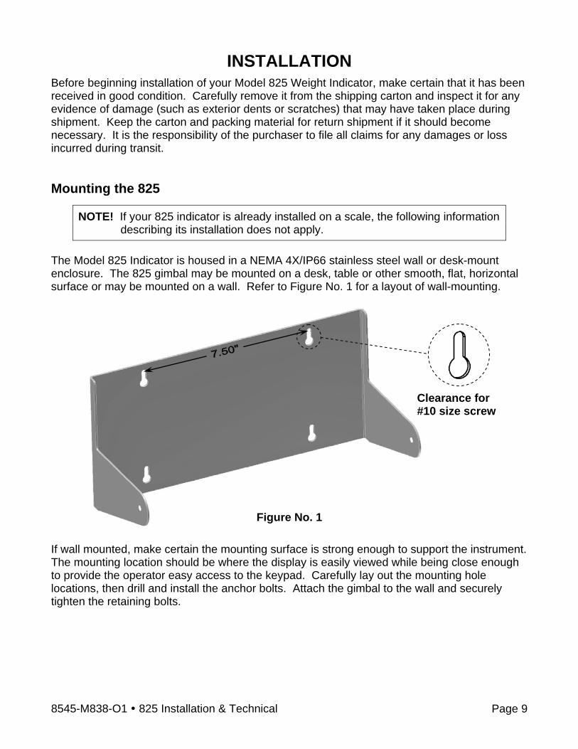
INSTALLATION Before beginning installation of your Model 825 Weight Indicator, make certain that it has been received in good condition. Carefully remove it from the shipping carton and inspect it for any evidence of damage (such as exterior dents or scratches) that may have taken place during shipment. Keep the carton and packing material for return shipment if it should become necessary. It is the responsibility of the purchaser to file all claims for any damages or loss incurred during transit. Mounting the 825
NOTE! If your 825 indicator is already installed on a scale, the following information describing its installation does not apply.
The Model 825 Indicator is housed in a NEMA 4X/IP66 stainless steel wall or desk-mount enclosure. The 825 gimbal may be mounted on a desk, table or other smooth, flat, horizontal surface or may be mounted on a wall. Refer to Figure No. 1 for a layout of wall-mounting.
If wall mounted, make certain the mounting surface is strong enough to support the instrument. The mounting location should be where the display is easily viewed while being close enough to provide the operator easy access to the keypad. Carefully lay out the mounting hole locations, then drill and install the anchor bolts. Attach the gimbal to the wall and securely tighten the retaining bolts.
Figure No. 1
Clearance for #10 size screw

8545-M838-O1 825 Installation & Technical Page 10
CAUTION! Disconnect any external load cell power supply before connecting load cells to the indicator. Failure to do so will result in permanent damage to the indicator.
INSTALLATION, CONT. Load Cell Cable Connection with RFI Suppression
Figure No. 2 To eliminate RFI, the load cell cable should be routed through the special metallic gland connector and the shield wire from the load cell cable must be connected to this gland connector for grounding. Refer to Figure No. 2 for the gland connector layout. 1. Remove the 14 acorn nuts securing the
rear panel to the main housing. 2. Loosen and remove the metal gland
connector nut and remove the plastic insert.
3. Referring to Figure No. 3, route the single cable from the load cell or load cell junction box through the nut and plastic insert and into the enclosure.
4. With the load cell cable routed into the enclosure, refer to Figure No. 4 and then remove approximately 6 inches of the cable outer insulating jacket exposing the internal wires.
5. Next, cut the shield wire so that it extends past the outer jacket approximately 3/4 inch.
I/O (Serial, Isolated Inputs/Outputs) or Additional Scales
Scale
AC Power 90-264 VAC
0.4 Amp
10/100 LAN and USB Access Cover
Figure No. 3
Ground Lug

8545-M838-O1 825 Installation & Technical Page 11
INSTALLATION, CONT.
6. Now, remove 1/4 inch of insulation from the end of each of the six wires (with sense leads) or four wires (without sense leads).
7. Remove the screw securing the 825 Scale Input Board (825-SIB) to the main PC board and then lift the 825-SIB straight up to remove it from the enclosure. See Figure No. 5.
8. Remove the 7-connector
terminal from the 825-SIB (hold the board in place and grasp the terminal block connector and lift straight up away from the board. See Figure No. 6.
6 inches
3/4 inch
1/4 inchFigure No. 4
Remove this screw
CAUTION! Be careful not to strike board against side of 825 enclosure when removing.
Figure No. 5
Hold board. Grasp here and lift up.
Figure No. 6
8545-M838-O1 825 Installation & Technical Page 12
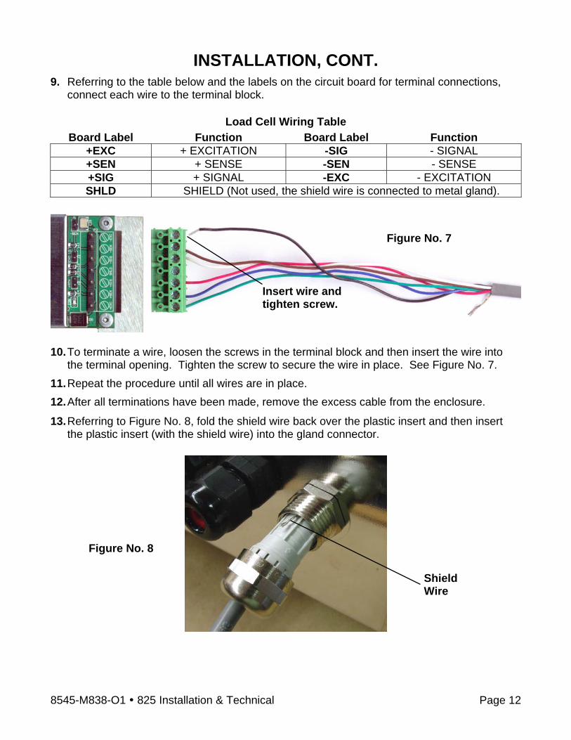
INSTALLATION, CONT. 9. Referring to the table below and the labels on the circuit board for terminal connections,
connect each wire to the terminal block.
Load Cell Wiring Table Board Label Function Board Label Function
+EXC + EXCITATION -SIG - SIGNAL +SEN + SENSE -SEN - SENSE +SIG + SIGNAL -EXC - EXCITATION SHLD SHIELD (Not used, the shield wire is connected to metal gland).
10. To terminate a wire, loosen the screws in the terminal block and then insert the wire into
the terminal opening. Tighten the screw to secure the wire in place. See Figure No. 7. 11. Repeat the procedure until all wires are in place. 12. After all terminations have been made, remove the excess cable from the enclosure.
13. Referring to Figure No. 8, fold the shield wire back over the plastic insert and then insert the plastic insert (with the shield wire) into the gland connector.
Figure No. 8
Shield Wire
Insert wire and tighten screw.
Figure No. 7

8545-M838-O1 825 Installation & Technical Page 13
INSTALLATION, CONT. 14. The shield wire is secured when tightening the gland connector nut. See Figure No. 9.
15. Do not over-tighten the connector but make certain it is snug. Load Cell Cable Connection without RFI Suppression The following instructions describe the load cell connection without RFI Suppression should it not be required.
1. Remove the 14 acorn nuts securing the rear panel to the main housing. 2. Referring to Figure No. 2, choose a gland connector for the load cell cable and loosen it. 3. Slip the single cable from the load cell or load cell junction box through the gland connector
and into the enclosure. 4. Referring to Figure No. 4, remove 3 inches (not 6 inches) of the outer insulation jacket 5. Next, remove 1/4 inch of insulation from each of the six wires and shield (with sense leads)
or four wires and shield (with sense leads). 6. Referring to the table below and the labels on the circuit board for terminal connections,
connect each wire to the terminal block.
Load Cell Wiring Table Board Label Function Board Label Function
+EXC + EXCITATION -SIG - SIGNAL +SEN + SENSE -SEN - SENSE +SIG + SIGNAL -EXC - EXCITATION SHLD SHIELD (Connect the load cell cable shield wire here).
7. To terminate a wire, loosen the screws in the terminal block and then insert the wire into
the terminal opening. Tighten the screw to secure the wire in place. See Figure No. 7. 8. Repeat the procedure until all wires are in place.
Figure No. 9 Shield Wire

8545-M838-O1 825 Installation & Technical Page 14
INSTALLATION, CONT. Load Cell Connections with Over 30 Feet of Cable For installations with over 30 feet of cable between the 825 and the load cells, sense wires should be used. The sense wires must be connected between the +SENS, -SENS terminals on the 825-SIB (Scale Input Board) and the +EXCITATION, -EXCITATION wires of the load cells or the +SENS, -SENS terminals of the load cell trim board (or the section seal trim board). For the 825-SIB to use the sense wires, the -SENS and +SENS jumpers J1 and J3 must be open (on one pin only) or removed. Refer to Figure No. 10 for the location of these jumpers. 825-SIB (Scale Input Board) P1 – FACTORY USE ONLY P3 – LOAD CELL TERMINAL
Board Label Function Board Label Function +EXC + EXCITATION -SIG - SIGNAL +SEN + SENSE -SEN - SENSE +SIG + SIGNAL -EXC - EXCITATION SHLD SHIELD
J1 (-SEN) and J3 (+SEN) – SENSE JUMPERS If the sense leads are NOT used, you must install the -SEN and +SEN jumpers at J1 and J3 (near the P3 terminal block). These jumpers connect the sense leads to the excitation leads. If sense leads ARE used (as in motor truck scales or installations with over 30 feet between the indicator and load cells), these jumpers should be open (on one pin only) or removed. J2 (DEAD LD) – DEAD LOAD BOOST JUMPER For scales with very low dead loads (less than 10% of the combined load cell capacity), connect the DEAD LD (dead load boost) jumper J2 (near the P3 terminal block).
J1 (-SEN)
J3 (+SEN)
J2 (DEAD LD)
P3
Figure No. 10
P1

8545-M838-O1 825 Installation & Technical Page 15
INSTALLATION, CONT. I/O Cable Preparation and Installation The 825 indicator may be connected to a printer to record weight and associated data or it may be connected to a remote display or even to a computer for transmission of weight data. The weight data may be transmitted on demand (pressing the PRINT key or on receipt of a command from the computer). 1. If the rear panel of the indicator has been removed, proceed to step 2. Otherwise, remove
the 14 acorn nuts securing the rear panel to the main housing. 2. Referring to Figure No. 2, choose a gland connector for the I/O cable and loosen it. 3. Slip the cable through the gland connector and into the enclosure. 4. Referring to Figure No. 4, remove 3 inches (not 6 inches) of the outer insulation jacket 5. Next, remove 1/4 inch of insulation from each of the wires. 6. Referring to the corresponding I/O tables and figures in the next sections, connect each
wire to the terminal block. 7. To terminate a wire, loosen the screws in the terminal block and then insert the wire into
the terminal opening. Tighten the screw to secure the wire in place. 8. Repeat the procedure until all wires are in place. RS232 Terminal Connections Refer to the table and Figure No. 11 below to connect each wire to the terminal block.
RS232 COM1, COM2, and COM3 TERMINALS P22, P21 and P20
Terminal Function 1 TXD (Transmit) 2 RXD (Receive) 3 RTS (Ready To Send) 4 CTS (Clear To Send) 5 GND (Ground)
IMPORTANT!
• COM1 is RS232 only (no jumper or shunt). • COM2 requires J7 shunt installed on RS232. • COM3 requires J8 shunt installed on RS232.
Figure No. 11

8545-M838-O1 825 Installation & Technical Page 16
INSTALLATION, CONT. 20mA Terminal Connections Refer to the table and Figures No. 12 and 13 below to connect each wire to the terminal block.
20mA COM2 – TERMINAL P21 Terminal Function
1 TXA (Transmit A) 2 TXB (Transmit B) 3 RXA (Receive A) 4 RXB (Receive B) 5 GND (Ground)
IMPORTANT!
• COM2 requires J7 shunt installed on 20mA. • 825 Active requires J3 installed. • 825 Passive requires J3 removed.
Figure No. 12 Figure No. 13
8545-M838-O1 825 Installation & Technical Page 17
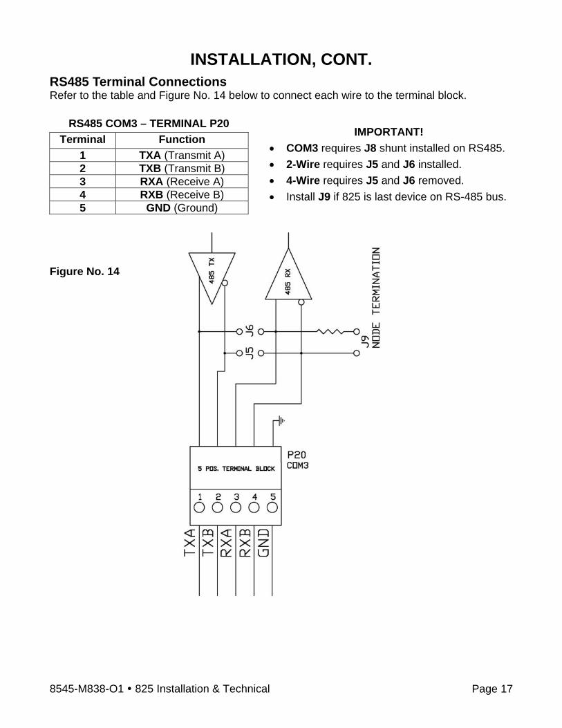
INSTALLATION, CONT. RS485 Terminal Connections Refer to the table and Figure No. 14 below to connect each wire to the terminal block.
RS485 COM3 – TERMINAL P20 Terminal Function
1 TXA (Transmit A) 2 TXB (Transmit B) 3 RXA (Receive A) 4 RXB (Receive B) 5 GND (Ground)
IMPORTANT! • COM3 requires J8 shunt installed on RS485. • 2-Wire requires J5 and J6 installed. • 4-Wire requires J5 and J6 removed. • Install J9 if 825 is last device on RS-485 bus.
Figure No. 14
8545-M838-O1 825 Installation & Technical Page 18
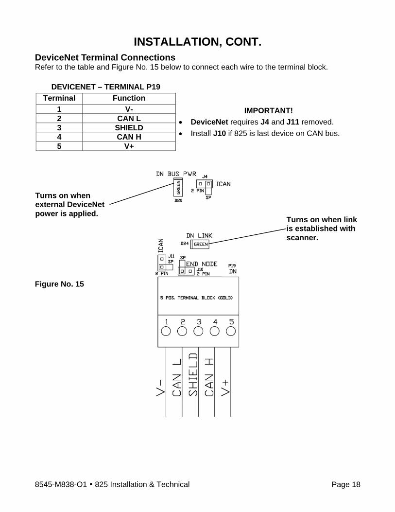
INSTALLATION, CONT. DeviceNet Terminal Connections Refer to the table and Figure No. 15 below to connect each wire to the terminal block.
DEVICENET – TERMINAL P19 Terminal Function
1 V- 2 CAN L 3 SHIELD 4 CAN H 5 V+
IMPORTANT! • DeviceNet requires J4 and J11 removed. • Install J10 if 825 is last device on CAN bus.
Turns on when external DeviceNet power is applied.
Turns on when link is established with scanner.
Figure No. 15
8545-M838-O1 825 Installation & Technical Page 19
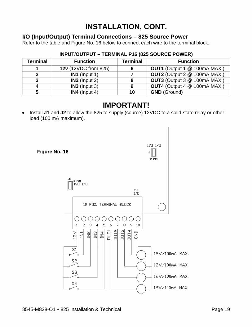
INSTALLATION, CONT. I/O (Input/Output) Terminal Connections – 825 Source Power Refer to the table and Figure No. 16 below to connect each wire to the terminal block.
INPUT/OUTPUT – TERMINAL P16 (825 SOURCE POWER) Terminal Function Terminal Function
1 12v (12VDC from 825) 6 OUT1 (Output 1 @ 100mA MAX.) 2 IN1 (Input 1) 7 OUT2 (Output 2 @ 100mA MAX.) 3 IN2 (Input 2) 8 OUT3 (Output 3 @ 100mA MAX.) 4 IN3 (Input 3) 9 OUT4 (Output 4 @ 100mA MAX.) 5 IN4 (Input 4) 10 GND (Ground)
IMPORTANT!
• Install J1 and J2 to allow the 825 to supply (source) 12VDC to a solid-state relay or other load (100 mA maximum).
Figure No. 16
8545-M838-O1 825 Installation & Technical Page 20
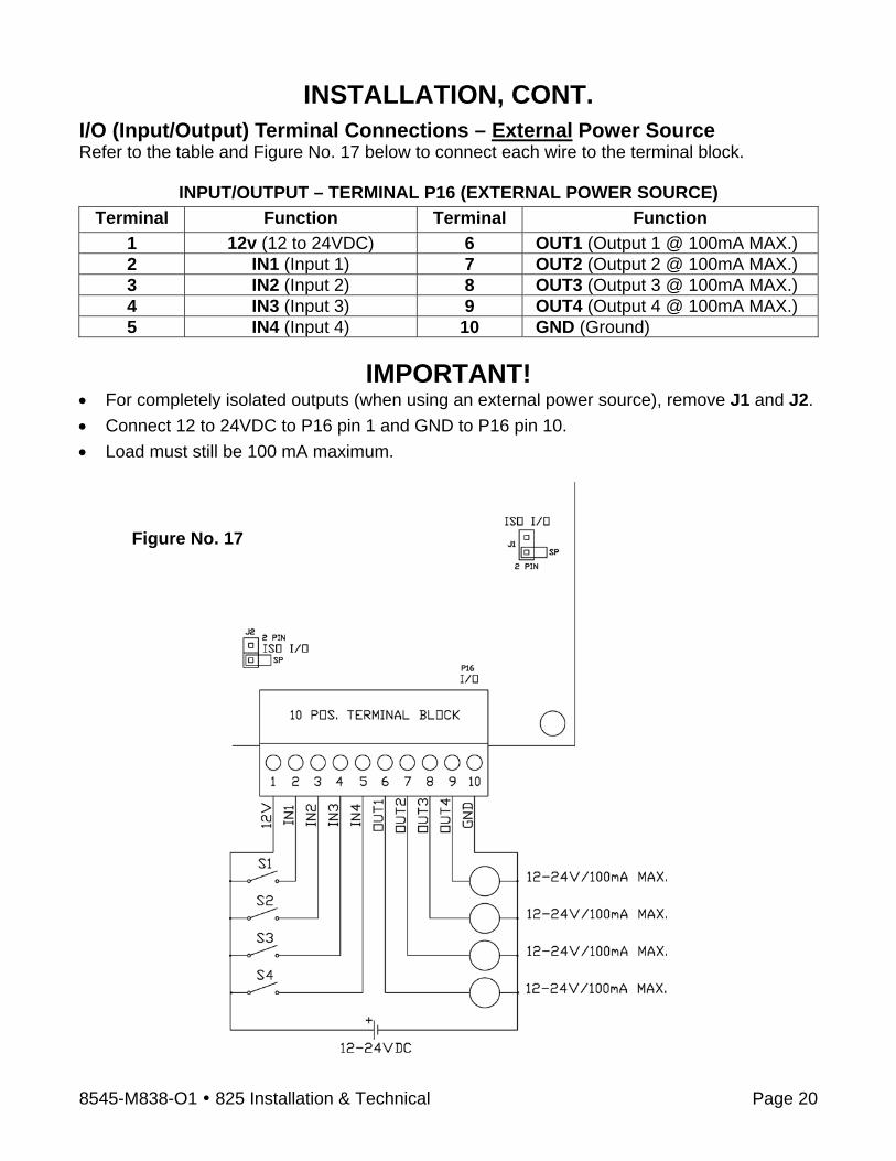
INSTALLATION, CONT. I/O (Input/Output) Terminal Connections – External Power Source Refer to the table and Figure No. 17 below to connect each wire to the terminal block.
INPUT/OUTPUT – TERMINAL P16 (EXTERNAL POWER SOURCE) Terminal Function Terminal Function
1 12v (12 to 24VDC) 6 OUT1 (Output 1 @ 100mA MAX.) 2 IN1 (Input 1) 7 OUT2 (Output 2 @ 100mA MAX.) 3 IN2 (Input 2) 8 OUT3 (Output 3 @ 100mA MAX.) 4 IN3 (Input 3) 9 OUT4 (Output 4 @ 100mA MAX.) 5 IN4 (Input 4) 10 GND (Ground)
IMPORTANT!
• For completely isolated outputs (when using an external power source), remove J1 and J2. • Connect 12 to 24VDC to P16 pin 1 and GND to P16 pin 10. • Load must still be 100 mA maximum.
Figure No. 17
8545-M838-O1 825 Installation & Technical Page 21
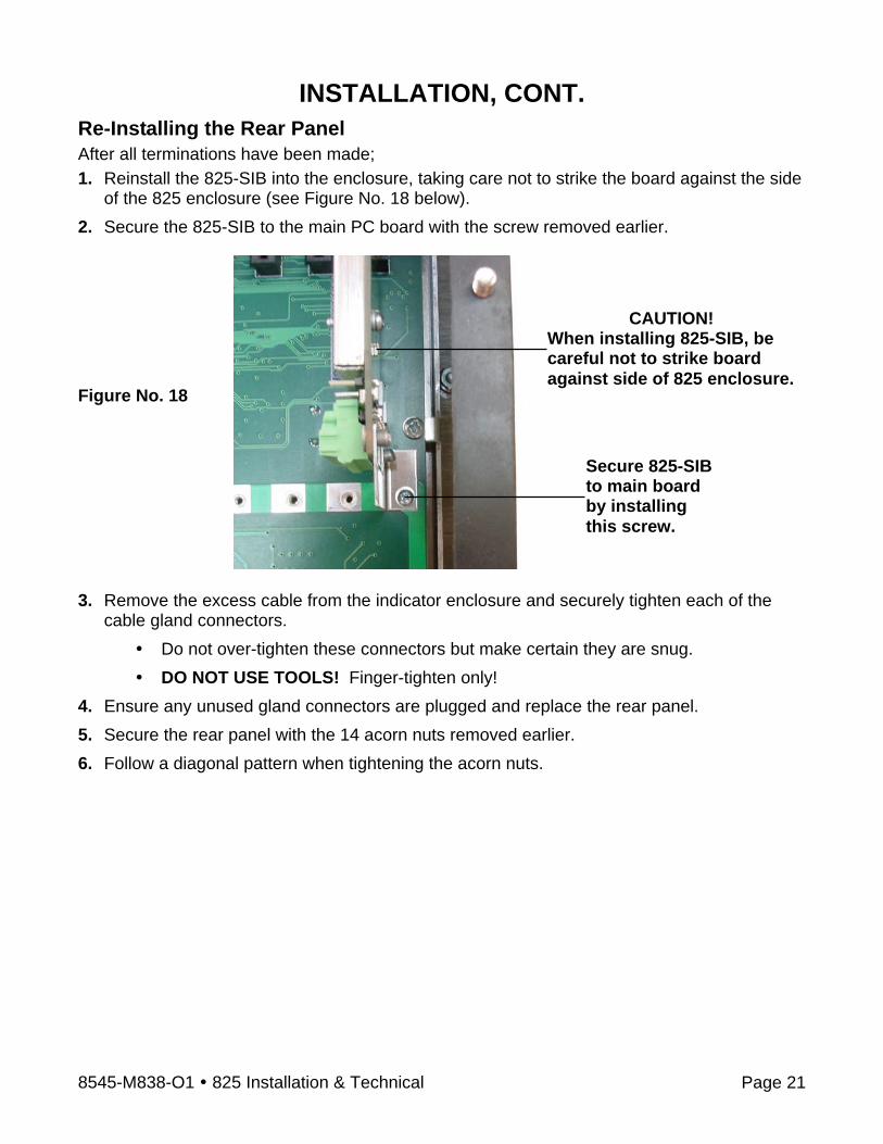
INSTALLATION, CONT. Re-Installing the Rear Panel After all terminations have been made; 1. Reinstall the 825-SIB into the enclosure, taking care not to strike the board against the side
of the 825 enclosure (see Figure No. 18 below). 2. Secure the 825-SIB to the main PC board with the screw removed earlier.
3. Remove the excess cable from the indicator enclosure and securely tighten each of the
cable gland connectors. Do not over-tighten these connectors but make certain they are snug. DO NOT USE TOOLS! Finger-tighten only!
4. Ensure any unused gland connectors are plugged and replace the rear panel. 5. Secure the rear panel with the 14 acorn nuts removed earlier. 6. Follow a diagonal pattern when tightening the acorn nuts.
Secure 825-SIB to main board by installing this screw.
CAUTION! When installing 825-SIB, be careful not to strike board against side of 825 enclosure.
Figure No. 18
8545-M838-O1 825 Installation & Technical Page 22
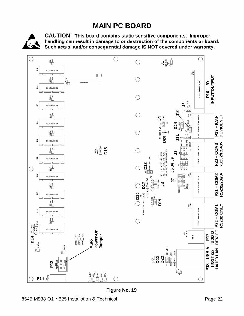
MAIN PC BOARD CAUTION! This board contains static sensitive components. Improper handling can result in damage to or destruction of the components or board. Such actual and/or consequential damage IS NOT covered under warranty.
P19
– IC
AN
D
EVIC
ENET
J4
Figure No. 19
P16
– I/O
IN
PUT/
OU
TPU
T
D15
J3
D14
P13
P14
P20
– C
OM
3 R
S232
/RS4
85
P21
– C
OM
2 R
S232
/20m
A
P22
– C
OM
1 R
S232
ON
LY
P17
USB
B
DEV
ICE
P18
– U
SB A
H
OST
(2)
10/1
00 L
AN
D21
D
22
D23
D18
D16
D
17
D19
D
20
J2
D24
J1
0 J8
J5
J6
J9
J11
J7
Aut
o Po
we r
-On
Jum
per
J1
8545-M838-O1 825 Installation & Technical Page 23
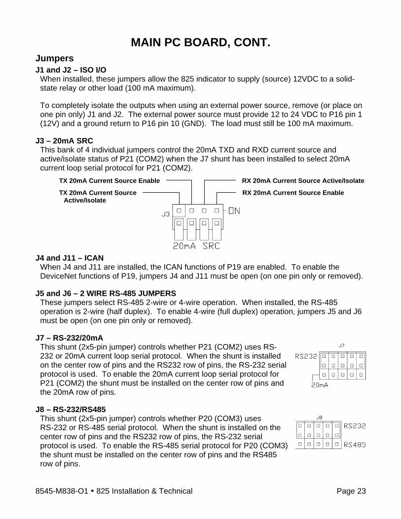
MAIN PC BOARD, CONT. Jumpers J1 and J2 – ISO I/O
When installed, these jumpers allow the 825 indicator to supply (source) 12VDC to a solid-state relay or other load (100 mA maximum).
To completely isolate the outputs when using an external power source, remove (or place on one pin only) J1 and J2. The external power source must provide 12 to 24 VDC to P16 pin 1 (12V) and a ground return to P16 pin 10 (GND). The load must still be 100 mA maximum.
J3 – 20mA SRC
This bank of 4 individual jumpers control the 20mA TXD and RXD current source and active/isolate status of P21 (COM2) when the J7 shunt has been installed to select 20mA current loop serial protocol for P21 (COM2).
TX 20mA Current Source Enable RX 20mA Current Source Active/Isolate
TX 20mA Current Source RX 20mA Current Source Enable Active/Isolate
J4 and J11 – ICAN When J4 and J11 are installed, the ICAN functions of P19 are enabled. To enable the DeviceNet functions of P19, jumpers J4 and J11 must be open (on one pin only or removed).
J5 and J6 – 2 WIRE RS-485 JUMPERS
These jumpers select RS-485 2-wire or 4-wire operation. When installed, the RS-485 operation is 2-wire (half duplex). To enable 4-wire (full duplex) operation, jumpers J5 and J6 must be open (on one pin only or removed).
J7 – RS-232/20mA
This shunt (2x5-pin jumper) controls whether P21 (COM2) uses RS-232 or 20mA current loop serial protocol. When the shunt is installed on the center row of pins and the RS232 row of pins, the RS-232 serial protocol is used. To enable the 20mA current loop serial protocol for P21 (COM2) the shunt must be installed on the center row of pins and the 20mA row of pins.
J8 – RS-232/RS485
This shunt (2x5-pin jumper) controls whether P20 (COM3) uses RS-232 or RS-485 serial protocol. When the shunt is installed on the center row of pins and the RS232 row of pins, the RS-232 serial protocol is used. To enable the RS-485 serial protocol for P20 (COM3) the shunt must be installed on the center row of pins and the RS485 row of pins.
8545-M838-O1 825 Installation & Technical Page 24
MAIN PC BOARD, CONT. J9 – NODE TERMINATION
This jumper is for the RS-485 node termination selection. When installed, the RS-485 node is terminated indicating the 825 is the last device on the RS-485 bus. If the 825 is not the last device on the RS-485 bus (e.g., it is in the middle of the bus), then it must be un-terminated and jumper J9 must be open (on one pin only or removed).
J10 – END NODE
This jumper is for the CAN bus end node selection. Install this jumper when the 825 is the last device on the CAN bus. When the 825 is not the last device on the CAN bus (e.g., it is in the middle of the bus), then J10 must be open (on one pin only or removed).
Connectors
P3 = PCI Express connector for standard Scale Input Board (825-SIB). P4 to P12 = PCI Express connectors for 825 option cards. P13 = Program connector and auto power-on jumper (pins 2 and 4).
When a jumper is installed across pins 2 and 4 of this connector, whenever power is applied to the indicator, it will turn on automatically without pressing the ON/OFF key. This is especially useful if power is lost momentarily and then reapplied.
P14 = Power connector. P15 = BDM connector (For Factory Use only). P16 = I/O (Input/Output) 10 position terminal block. P17 = USB B Device connector. P18 = USB A Host (2) and 10/100 LAN connector. P19 = DeviceNet/ICAN 5 position terminal block. P20 = COM3 (RS-232/RS-485) 5 position terminal block. P21 = COM2 (RS-232/20mA) 5 position terminal block. P22 = COM1 (RS-232 only) 5 position terminal block.
Status LED’S
D14 = Turned on to indicate the 12 VDC supply exceeds 2A. D15 = For Factory Use only. D16 = Turned on to indicate the 20mA TXD SRC (transmit current source) is enabled. D17 = Turned on to indicate 20mA is present in TXD (transmit) loop. D18 = Turned on to indicate the 20mA RXD SRC (receive current source) is enabled. D19 = Turned on to indicate 20mA is present in RXD (receive) loop. D20 = Turned on when external DeviceNet power is applied. D21 = Blinks when the USB hub is enabled. D22 = Turned on to indicate the USB1 host is enabled. D23 = Turned on to indicate the USB2 host is enabled. D24 = Turned on to indicate the DeviceNet link with the PLC is established.
8545-M838-O1 825 Installation & Technical Page 25
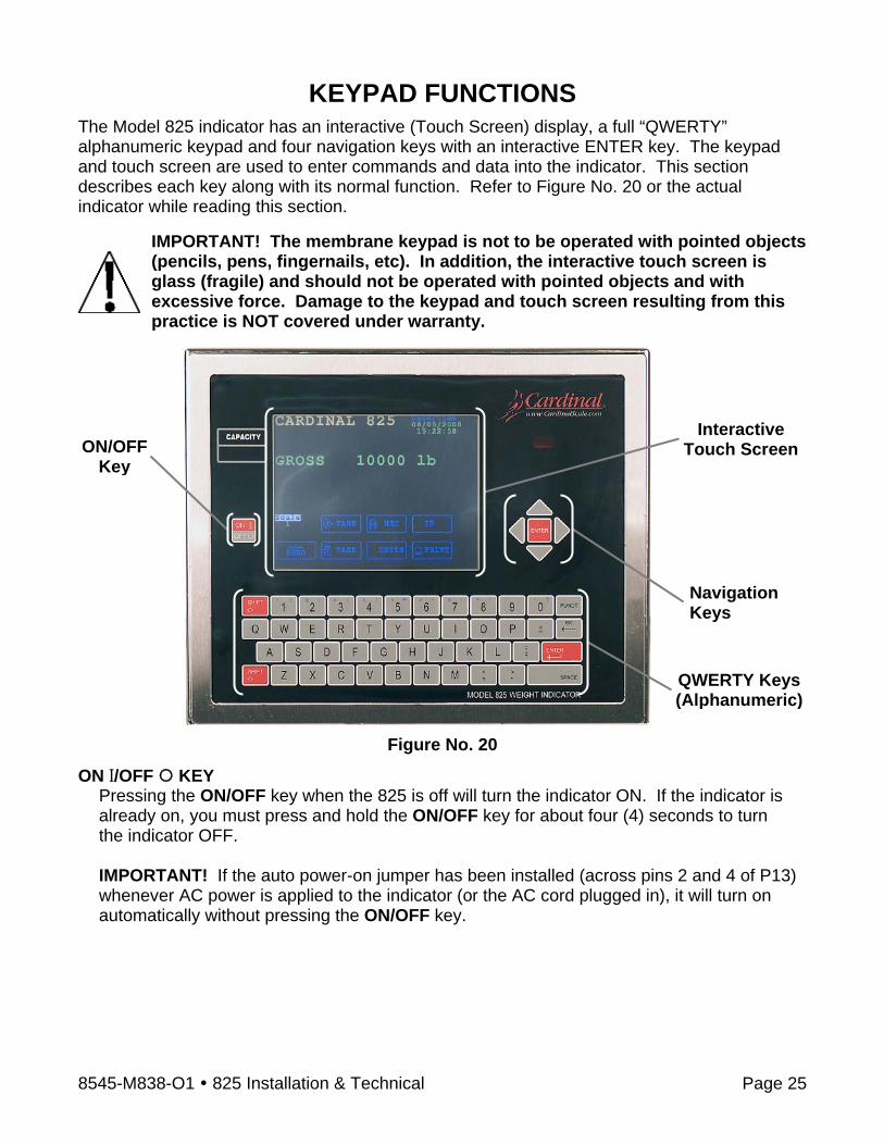
KEYPAD FUNCTIONS The Model 825 indicator has an interactive (Touch Screen) display, a full “QWERTY” alphanumeric keypad and four navigation keys with an interactive ENTER key. The keypad and touch screen are used to enter commands and data into the indicator. This section describes each key along with its normal function. Refer to Figure No. 20 or the actual indicator while reading this section.
IMPORTANT! The membrane keypad is not to be operated with pointed objects (pencils, pens, fingernails, etc). In addition, the interactive touch screen is glass (fragile) and should not be operated with pointed objects and with excessive force. Damage to the keypad and touch screen resulting from this practice is NOT covered under warranty.
Figure No. 20
ON I/OFF KEY Pressing the ON/OFF key when the 825 is off will turn the indicator ON. If the indicator is already on, you must press and hold the ON/OFF key for about four (4) seconds to turn the indicator OFF. IMPORTANT! If the auto power-on jumper has been installed (across pins 2 and 4 of P13) whenever AC power is applied to the indicator (or the AC cord plugged in), it will turn on automatically without pressing the ON/OFF key.
Interactive Touch Screen
QWERTY Keys(Alphanumeric)
Navigation Keys
ON/OFF Key
8545-M838-O1 825 Installation & Technical Page 26
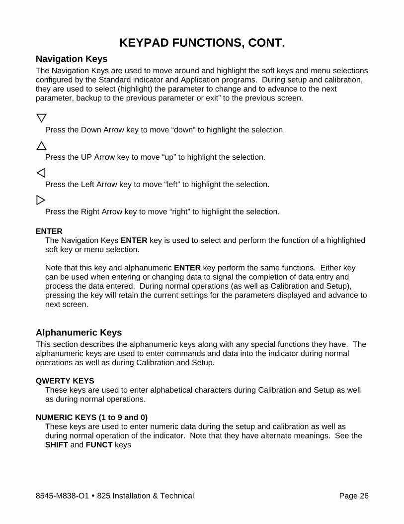
KEYPAD FUNCTIONS, CONT. Navigation Keys The Navigation Keys are used to move around and highlight the soft keys and menu selections configured by the Standard indicator and Application programs. During setup and calibration, they are used to select (highlight) the parameter to change and to advance to the next parameter, backup to the previous parameter or exit” to the previous screen.
Press the Down Arrow key to move “down” to highlight the selection.
Press the UP Arrow key to move “up” to highlight the selection.
Press the Left Arrow key to move “left” to highlight the selection.
Press the Right Arrow key to move “right” to highlight the selection.
ENTER
The Navigation Keys ENTER key is used to select and perform the function of a highlighted soft key or menu selection.
Note that this key and alphanumeric ENTER key perform the same functions. Either key can be used when entering or changing data to signal the completion of data entry and process the data entered. During normal operations (as well as Calibration and Setup), pressing the key will retain the current settings for the parameters displayed and advance to next screen.
Alphanumeric Keys This section describes the alphanumeric keys along with any special functions they have. The alphanumeric keys are used to enter commands and data into the indicator during normal operations as well as during Calibration and Setup. QWERTY KEYS
These keys are used to enter alphabetical characters during Calibration and Setup as well as during normal operations.
NUMERIC KEYS (1 to 9 and 0)
These keys are used to enter numeric data during the setup and calibration as well as during normal operation of the indicator. Note that they have alternate meanings. See the SHIFT and FUNCT keys

8545-M838-O1 825 Installation & Technical Page 27
KEYPAD FUNCTIONS, CONT. Alphanumeric Keys, Cont. SHIFT
Pressing this key before pressing an alphanumeric key will cause the key to output its alternate meaning. When combined with the QWERTY (alphabetic) keys, the SHIFT key causes a lower case (not a capital letter) to be output. For example, pressing the SHIFT key then the A key will output a lower case “a” (not a capital letter). Pressing the SHIFT key before pressing a numeric key will cause the key to output the black symbol (upper left of each key). For example, pressing the SHIFT key and then the 4 key will output the $ dollar sign.
FUNCT Pressing the blue FUNCT key before pressing a numeric key will cause the key to output the blue symbol (upper right of each key). For example, pressing the FUNCT key and then the 7 key will output the \ (backslash) character.
←⎯ /ESC
This key has several functions. When entering data (either during setup and calibration or during normal operation) pressing this key will delete (backspace) the last character entered. If more than the last character is incorrect, press the ←⎯ /ESC key for each character to be deleted. Note that the indicator will ignore pressing this key if no characters have been entered. When combined with the SHIFT key (pressing the SHIFT key and then the ←⎯ /ESC key), the display will "escape” (return or backup) to the previous screen.
ENTER
The ENTER key is used when entering or changing data to signal the completion of data entry and process the data entered. During normal operations (as well as Calibration and Setup), pressing the key will retain the current settings for the parameters displayed and advance to next screen. Note that this key and the Navigation Keys ENTER key perform the same functions. Either key can be used to select and perform the function of a highlighted soft key or menu selection.
SPACE This key is used to enter a blank space during alphanumeric data input for setup and calibration as well as during normal operations. In addition, some parameters in setup and calibration require pressing the SPACE key to toggle its status or to step through the available selections.

8545-M838-O1 825 Installation & Technical Page 28
KEYPAD FUNCTIONS, CONT. Standard Indicator Keys This section describes the Standard Indicator keys (displayed on the Weight screen) along with their functions as programmed by the 825 Standard indicator menu selection. Refer to the actual indicator screen while reading this section.
IMPORTANT! In order to use the Standard Indicator keys, the operator must press the alphanumeric letter key corresponding to the underlined letter on the key (e.g., Z for the Zero key) or the first letter on the key (e.g., O for Operator) to perform the key function. Note that the Navigation Keys can be used to select (highlight) the key and then after pressing the ENTER key, the key function will be performed.
Operator
Pressing the O key will prompt for the input of a new operator. 1. The display will change to show the Login screen. 2. Enter the login and then press the Down Arrow to advance to the password prompt. 3. Enter the password and then press the ENTER key to proceed. 4. Otherwise, press the ESC key to return to the Weight screen.
Scale
Pressing the S key (with multiple scales) will toggle through the available scales and, if enabled, the totalizer. Note that pressing this key with only one scale, the screen will display the message Only one scale.
Date/Time Pressing the D key allows the operator to change the date and time. For information on changing the date and time, refer to the Setting Date and Time section of this manual.
TARE (Key Entry Tare)
This key allows the operator to enter a tare weight (up to the capacity of the scale). Note that the tare weight is the amount of weight to be subtracted from the gross weight to obtain the net weight. 1. Press the T key. 2. The display will change to show the Set Tare screen. 3. Using the numeric keys (use the period for the decimal point), enter the tare weight and
then press the ENTER key. 4. The display will return to the Weight screen, showing the Gross, Tare and Net weights. IMPORTANT! The tare weight will remain until another tare weight is entered or it is cleared. Clearing the tare weight can be only performed when zero weight is on the scale.
1. With the zero weight on the scale, press the A (TARE (Pushbutton Tare) key. 2. The display will return to the Weight screen, showing gross weight only.
8545-M838-O1 825 Installation & Technical Page 29
KEYPAD FUNCTIONS, CONT. Standard Indicator Keys, Cont. NET/GROSS
Pressing the N key (if in Gross mode) or the G key (if in Net mode) will toggle between the Gross weight and Net weight. In the Gross weight mode, the total of all weight placed on the scale since the display was zeroed is displayed. In the Net Weight mode, the Gross, Tare and Net weight is displayed. IMPORTANT! If a valid tare weight has not been entered, pressing this key will momentarily display the message:
Cannot show net – tare zero
The display will return to the Weight screen, showing gross weight only ID
This key allows the operator to enter an ID (identification) for use in printing. Note that after entering an ID, it will be displayed on the Weight screen below the ID key.
1. Press the I key. 2. The display will change to show the Set ID screen. 3. Using the alphanumeric keys, enter up to a ten (10) character ID and then press the
ENTER key to save it. IMPORTANT! Once an ID has been entered, it will remain until another ID is entered or it is cleared.
1. To clear an ID, first press the I key. 2. With the Set ID screen displayed, press the SPACE key and then the ENTER key. 3. The display will return to the Weight screen with no ID shown below the ID key.
ZERO
Pressing the Z key allows the operator to reset the Gross weight to zero. IMPORTANT! If the gross weight exceeds the zero limit for this key, pressing this key will momentarily display the message:
CANNOT ZERO –
The display will return to the Weight screen, showing gross weight only
Note that the zero limit may be either 4% or 100% of the scale capacity. This limit is set during setup and calibration (see the Zero Limit parameter).
TARE (Pushbutton Tare)
Pressing the A key will act as a pushbutton tare and will store the current Gross weight as the new tare weight and will switch the display to the Net weight mode.

8545-M838-O1 825 Installation & Technical Page 30
KEYPAD FUNCTIONS, CONT. Standard Indicator Keys, Cont. UNITS
Pressing the U key will change the weighing units to the alternate units if available. For example, with lb (pounds) showing, pressing this key will change the weight units to kg (kilograms). IMPORTANT! This feature must be enabled during setup and calibration (see the Base Units and Conv Units parameters).
Pressing the P key will initiate the transmission of weight data to the ticket printer. If displaying Gross weight, the time, date and gross weight are printed. If displaying net weight, the time, date, gross, tare and net weights are printed. IMPORTANT! If the weight is less than zero (negative weight), pressing this key will momentarily display the message:
Cannot print BELOW ZERO –
The display will return to the Weight screen, showing gross weight only. Also, if the weight is unstable (motion on the scale), pressing this key will momentarily display the message:
Cannot print MOTION –
The display will return to the Weight screen, showing gross weight only
8545-M838-O1 825 Installation & Technical Page 31
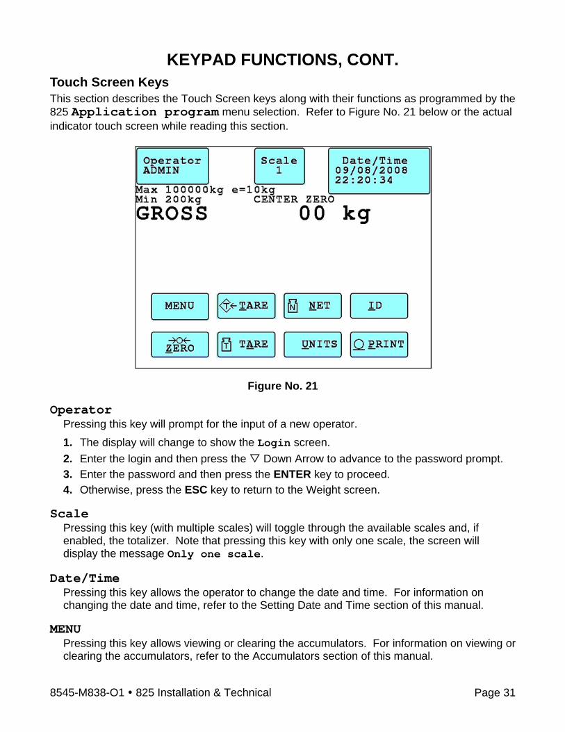
KEYPAD FUNCTIONS, CONT. Touch Screen Keys This section describes the Touch Screen keys along with their functions as programmed by the 825 Application program menu selection. Refer to Figure No. 21 below or the actual indicator touch screen while reading this section.
Figure No. 21 Operator
Pressing this key will prompt for the input of a new operator. 1. The display will change to show the Login screen. 2. Enter the login and then press the Down Arrow to advance to the password prompt. 3. Enter the password and then press the ENTER key to proceed. 4. Otherwise, press the ESC key to return to the Weight screen.
Scale
Pressing this key (with multiple scales) will toggle through the available scales and, if enabled, the totalizer. Note that pressing this key with only one scale, the screen will display the message Only one scale.
Date/Time
Pressing this key allows the operator to change the date and time. For information on changing the date and time, refer to the Setting Date and Time section of this manual.
MENU Pressing this key allows viewing or clearing the accumulators. For information on viewing or clearing the accumulators, refer to the Accumulators section of this manual.
8545-M838-O1 825 Installation & Technical Page 32
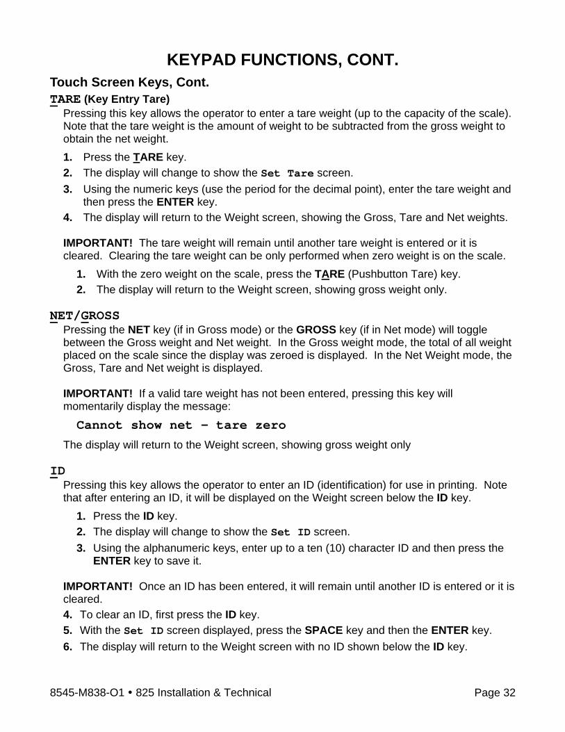
KEYPAD FUNCTIONS, CONT. Touch Screen Keys, Cont. TARE (Key Entry Tare)
Pressing this key allows the operator to enter a tare weight (up to the capacity of the scale). Note that the tare weight is the amount of weight to be subtracted from the gross weight to obtain the net weight. 1. Press the TARE key. 2. The display will change to show the Set Tare screen. 3. Using the numeric keys (use the period for the decimal point), enter the tare weight and
then press the ENTER key. 4. The display will return to the Weight screen, showing the Gross, Tare and Net weights. IMPORTANT! The tare weight will remain until another tare weight is entered or it is cleared. Clearing the tare weight can be only performed when zero weight is on the scale.
1. With the zero weight on the scale, press the TARE (Pushbutton Tare) key. 2. The display will return to the Weight screen, showing gross weight only.
NET/GROSS
Pressing the NET key (if in Gross mode) or the GROSS key (if in Net mode) will toggle between the Gross weight and Net weight. In the Gross weight mode, the total of all weight placed on the scale since the display was zeroed is displayed. In the Net Weight mode, the Gross, Tare and Net weight is displayed. IMPORTANT! If a valid tare weight has not been entered, pressing this key will momentarily display the message:
Cannot show net – tare zero
The display will return to the Weight screen, showing gross weight only ID
Pressing this key allows the operator to enter an ID (identification) for use in printing. Note that after entering an ID, it will be displayed on the Weight screen below the ID key.
1. Press the ID key. 2. The display will change to show the Set ID screen. 3. Using the alphanumeric keys, enter up to a ten (10) character ID and then press the
ENTER key to save it. IMPORTANT! Once an ID has been entered, it will remain until another ID is entered or it is cleared. 4. To clear an ID, first press the ID key. 5. With the Set ID screen displayed, press the SPACE key and then the ENTER key. 6. The display will return to the Weight screen with no ID shown below the ID key.

8545-M838-O1 825 Installation & Technical Page 33
KEYPAD FUNCTIONS, CONT. Touch Screen Keys, Cont. ZERO
This key allows the operator to reset the Gross weight to zero. IMPORTANT! If the gross weight exceeds the zero limit for this key, pressing this key will momentarily display the message:
CANNOT ZERO –
The display will return to the Weight screen, showing gross weight only
Note that the zero limit may be either 4% or 100% of the scale capacity. This limit is set during setup and calibration (see the Zero Limit parameter).
TARE (Pushbutton Tare)
Pressing this key will act as a pushbutton tare and will store the current Gross weight as the new tare weight and will switch the display to the Net weight mode.
UNITS
Pressing this key will change the weighing units to the alternate units if available. For example, with lb (pounds) showing, pressing this key will change the weight units to kg (kilograms). IMPORTANT! This feature must be enabled during setup and calibration (see the Base Units and Conv Units parameters).
Pressing this key will initiate the transmission of weight data to the ticket printer. If displaying Gross weight, the time, date and gross weight are printed. If displaying net weight, the time, date, gross, tare and net weights are printed. IMPORTANT! If the weight is less than zero (negative weight), pressing this key will momentarily display the message:
Cannot print BELOW ZERO –
The display will return to the Weight screen, showing gross weight only. Also, if the weight is unstable (motion on the scale), pressing this key will momentarily display the message:
Cannot print MOTION –
The display will return to the Weight screen, showing gross weight only

8545-M838-O1 825 Installation & Technical Page 34
ANNUNCIATORS The annunciators are displayed on the Weight screen to show that the 825 is in the mode corresponding to the annunciator label or that the status indicated by the label is active. CENTER ZERO This is shown on the Weight screen to indicate that the displayed (zero) weight is within +/- 1/4 division of the center of zero. GROSS This is shown on the Weight screen to indicate that the 825 is in the Gross weight mode. NET This is shown on the Weight screen when the 825 is in the Net weight mode. Note that the screen will display the Gross, Tare and Net weights. TARE This is shown on the Weight screen to indicate that a Tare weight has been stored. Note that the Gross and Net weights will be displayed also. tn This is displayed on the Weight screen to show that the weight units are avoirdupois tons. lb This is displayed on the Weight screen to show that the weight unit is pounds. t This is displayed on the Weight screen to show that the weight units are tonnes (metric tons). kg This is displayed on the Weight screen to show that the weight units are kilograms.

8545-M838-O1 825 Installation & Technical Page 35
SETTING THE DATE AND TIME With the Weight screen displayed, press the Date/Time key on the touch screen or use the Navigation Keys to select (highlight) the Date/Time key and then press the ENTER key. The display will change to show the Set Date/Time screen.
Year:
With the Set Date/Time screen displayed, the current setting for Year: will be shown. If the setting displayed is correct, press the Down Arrow to proceed to Month:. Otherwise, use the numeric keys to enter the year (e.g., 2008) and then press the Down Arrow to advance to Month:.
Month: With the Set Date/Time screen displayed, the current setting for Month: will be shown. If the setting displayed is correct, press the Down Arrow to proceed to Day:. Otherwise, use the numeric keys to enter the month (1 = Jan, 2 = Feb...12 = Dec) and then press the Down Arrow to advance to Day:.
Day: With the Set Date/Time screen displayed, the current setting for Day: will be shown. If the setting displayed is correct, press the Down Arrow to proceed to Hour:. Otherwise, use the numeric keys to enter the day of the month (1 to 31) and then press the
Down Arrow to advance to Hour:.
Hour: With the Set Date/Time screen displayed, the current setting for Hour: will be shown. If the setting displayed is correct, press the Down Arrow to proceed to Minute:. Otherwise, use the numeric keys to enter the hour in 24 hour time (e.g., 3 p.m. = 15) and then press the Down Arrow to advance to Minute:.
Minute: With the Set Date/Time screen displayed, the current setting for Minute: will be shown. If the setting displayed is correct, press the Down Arrow to proceed to Second:. Otherwise, use the numeric keys to enter the minutes (0 to 59 ) and then press the Down Arrow to advance to Second:.
Second: With the Set Date/Time screen displayed, the current setting for Second: will be shown. If the setting displayed is correct, press the ENTER key to save all of the new settings and return to the Weight screen. Otherwise, use the numeric keys to enter the seconds (0 to 59) and then press the ENTER key to save all of the new settings and return to the Weight screen.
8545-M838-O1 825 Installation & Technical Page 36
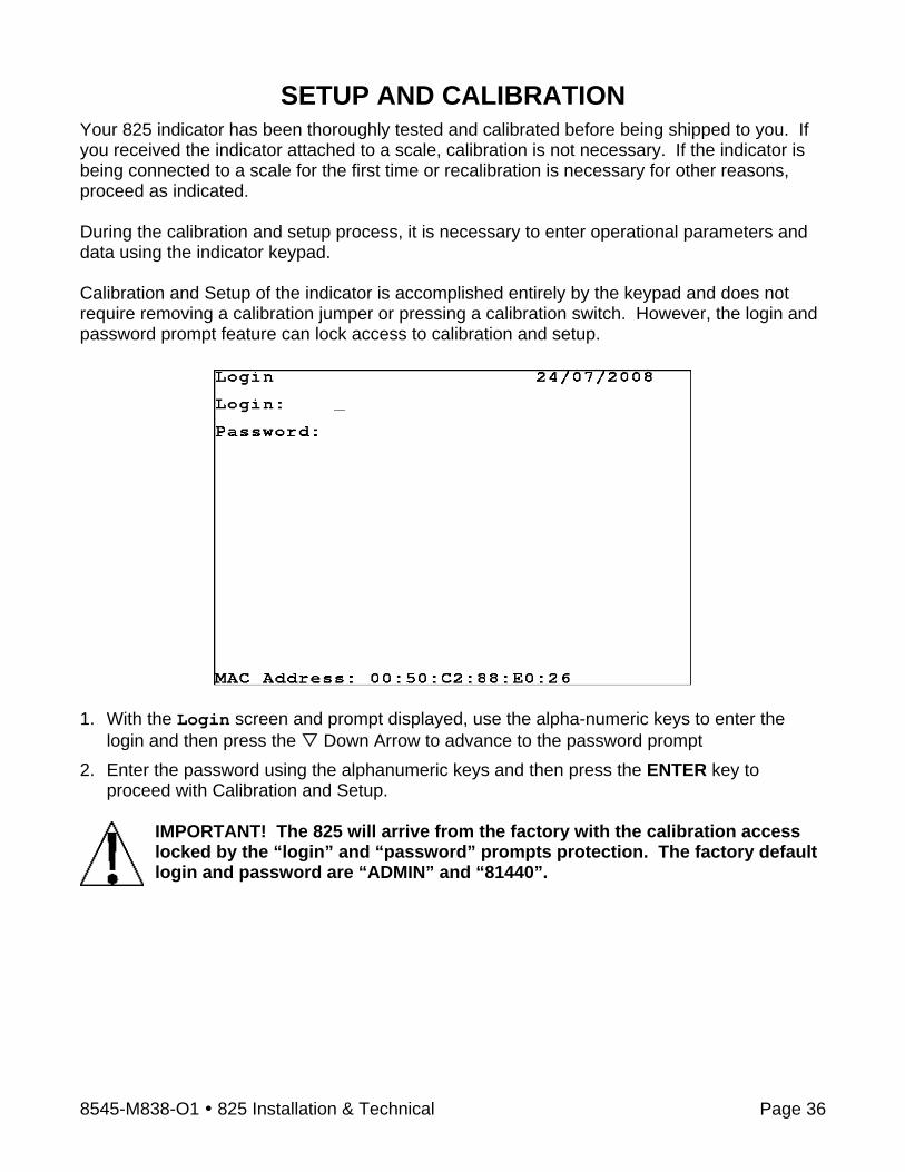
SETUP AND CALIBRATION Your 825 indicator has been thoroughly tested and calibrated before being shipped to you. If you received the indicator attached to a scale, calibration is not necessary. If the indicator is being connected to a scale for the first time or recalibration is necessary for other reasons, proceed as indicated. During the calibration and setup process, it is necessary to enter operational parameters and data using the indicator keypad. Calibration and Setup of the indicator is accomplished entirely by the keypad and does not require removing a calibration jumper or pressing a calibration switch. However, the login and password prompt feature can lock access to calibration and setup.
1. With the Login screen and prompt displayed, use the alpha-numeric keys to enter the
login and then press the Down Arrow to advance to the password prompt 2. Enter the password using the alphanumeric keys and then press the ENTER key to
proceed with Calibration and Setup.
IMPORTANT! The 825 will arrive from the factory with the calibration access locked by the “login” and “password” prompts protection. The factory default login and password are “ADMIN” and “81440”.
8545-M838-O1 825 Installation & Technical Page 37
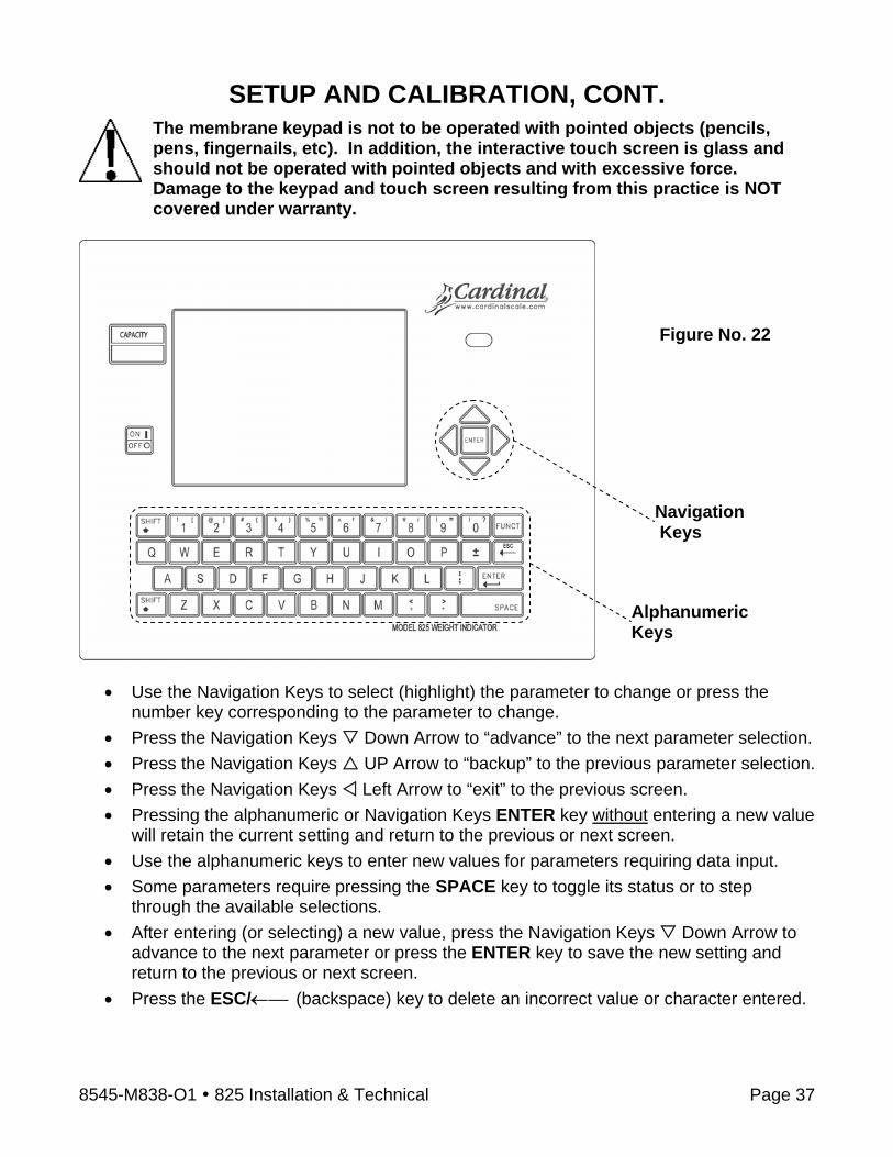
SETUP AND CALIBRATION, CONT. The membrane keypad is not to be operated with pointed objects (pencils, pens, fingernails, etc). In addition, the interactive touch screen is glass and should not be operated with pointed objects and with excessive force. Damage to the keypad and touch screen resulting from this practice is NOT covered under warranty.
• Use the Navigation Keys to select (highlight) the parameter to change or press the
number key corresponding to the parameter to change. • Press the Navigation Keys Down Arrow to “advance” to the next parameter selection. • Press the Navigation Keys UP Arrow to “backup” to the previous parameter selection. • Press the Navigation Keys Left Arrow to “exit” to the previous screen. • Pressing the alphanumeric or Navigation Keys ENTER key without entering a new value
will retain the current setting and return to the previous or next screen. • Use the alphanumeric keys to enter new values for parameters requiring data input. • Some parameters require pressing the SPACE key to toggle its status or to step
through the available selections. • After entering (or selecting) a new value, press the Navigation Keys Down Arrow to
advance to the next parameter or press the ENTER key to save the new setting and return to the previous or next screen.
• Press the ESC/←⎯ (backspace) key to delete an incorrect value or character entered.
Navigation Keys
AlphanumericKeys
Figure No. 22
8545-M838-O1 825 Installation & Technical Page 38
SETUP AND CALIBRATION, CONT. To Begin Setup and Calibration
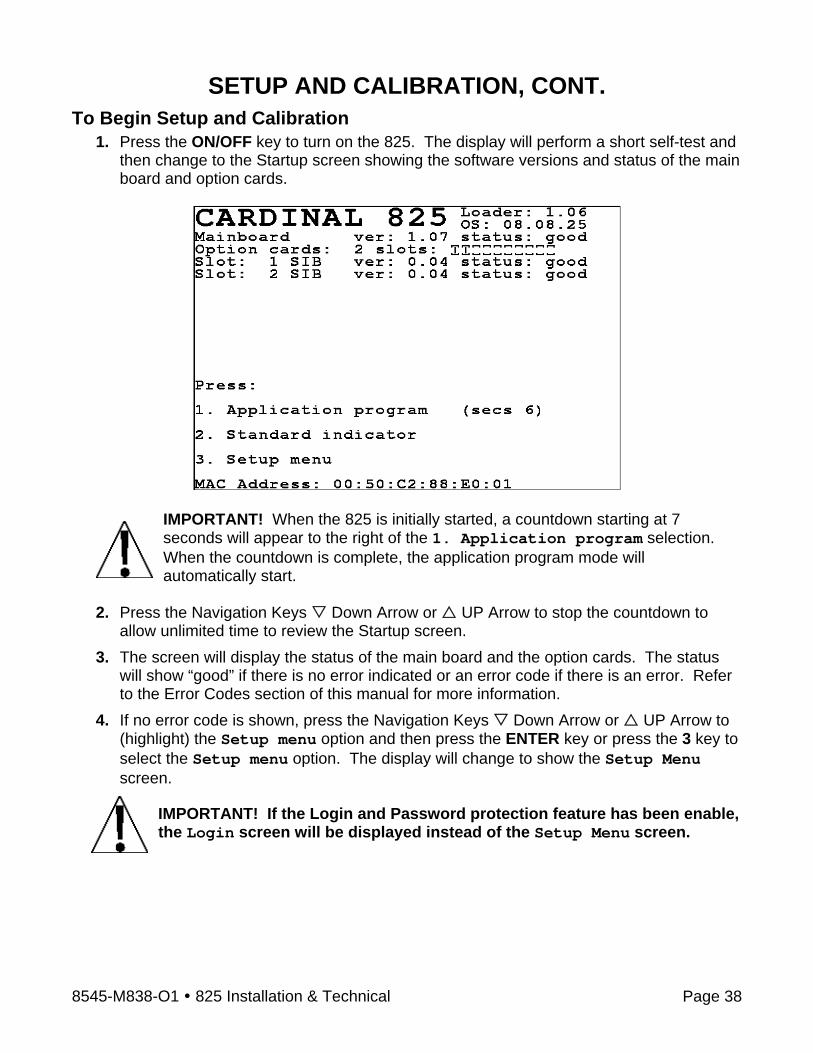
1. Press the ON/OFF key to turn on the 825. The display will perform a short self-test and then change to the Startup screen showing the software versions and status of the main board and option cards.
IMPORTANT! When the 825 is initially started, a countdown starting at 7 seconds will appear to the right of the 1. Application program selection. When the countdown is complete, the application program mode will automatically start.
2. Press the Navigation Keys Down Arrow or UP Arrow to stop the countdown to
allow unlimited time to review the Startup screen. 3. The screen will display the status of the main board and the option cards. The status
will show “good” if there is no error indicated or an error code if there is an error. Refer to the Error Codes section of this manual for more information.
4. If no error code is shown, press the Navigation Keys Down Arrow or UP Arrow to (highlight) the Setup menu option and then press the ENTER key or press the 3 key to select the Setup menu option. The display will change to show the Setup Menu screen.
IMPORTANT! If the Login and Password protection feature has been enable, the Login screen will be displayed instead of the Setup Menu screen.
8545-M838-O1 825 Installation & Technical Page 39
SETUP AND CALIBRATION, CONT.
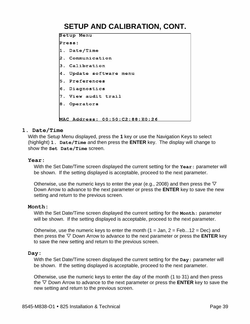
1. Date/Time
With the Setup Menu displayed, press the 1 key or use the Navigation Keys to select (highlight) 1. Date/Time and then press the ENTER key. The display will change to show the Set Date/Time screen. Year:
With the Set Date/Time screen displayed the current setting for the Year: parameter will be shown. If the setting displayed is acceptable, proceed to the next parameter. Otherwise, use the numeric keys to enter the year (e.g., 2008) and then press the Down Arrow to advance to the next parameter or press the ENTER key to save the new setting and return to the previous screen.
Month: With the Set Date/Time screen displayed the current setting for the Month: parameter will be shown. If the setting displayed is acceptable, proceed to the next parameter. Otherwise, use the numeric keys to enter the month (1 = Jan, 2 = Feb...12 = Dec) and then press the Down Arrow to advance to the next parameter or press the ENTER key to save the new setting and return to the previous screen.
Day: With the Set Date/Time screen displayed the current setting for the Day: parameter will be shown. If the setting displayed is acceptable, proceed to the next parameter. Otherwise, use the numeric keys to enter the day of the month (1 to 31) and then press the Down Arrow to advance to the next parameter or press the ENTER key to save the new setting and return to the previous screen.

8545-M838-O1 825 Installation & Technical Page 40
SETUP AND CALIBRATION, CONT. Hour:
With the Set Date/Time screen displayed the current setting for the Hour: parameter will be shown. If the setting displayed is acceptable, proceed to the next parameter. Otherwise, use the numeric keys to enter the hour in 24 hour time (e.g., 3 p.m. = 15) and then press the Down Arrow to advance to the next parameter or press the ENTER key to save the new setting and return to the previous screen.
Minute: With the Set Date/Time screen displayed the current setting for the Minute: parameter will be shown. If the setting displayed is acceptable, proceed to the next parameter. Otherwise, use the numeric keys to enter the minutes (0 to 59 ) and then press the Down Arrow to advance to the next parameter or press the ENTER key to save the new setting and return to the previous screen.
Second: With the Set Date/Time screen displayed the current setting for the Second: parameter will be shown. If the setting displayed is acceptable, press the ENTER key or the Navigation Keys Left Arrow to return to the previous screen. Otherwise, use the numeric keys to enter the seconds (0 to 59) and then press the ENTER key to save the new setting and return to the previous screen.
8545-M838-O1 825 Installation & Technical Page 41
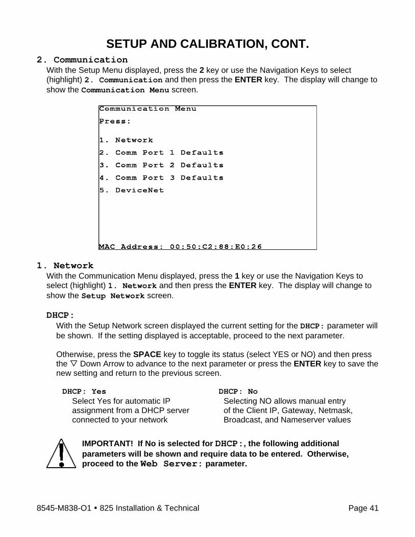
SETUP AND CALIBRATION, CONT. 2. Communication
With the Setup Menu displayed, press the 2 key or use the Navigation Keys to select (highlight) 2. Communication and then press the ENTER key. The display will change to show the Communication Menu screen.
1. Network
With the Communication Menu displayed, press the 1 key or use the Navigation Keys to select (highlight) 1. Network and then press the ENTER key. The display will change to show the Setup Network screen. DHCP:
With the Setup Network screen displayed the current setting for the DHCP: parameter will be shown. If the setting displayed is acceptable, proceed to the next parameter. Otherwise, press the SPACE key to toggle its status (select YES or NO) and then press the Down Arrow to advance to the next parameter or press the ENTER key to save the new setting and return to the previous screen. DHCP: Yes DHCP: No
Select Yes for automatic IP assignment from a DHCP server connected to your network
Selecting NO allows manual entry of the Client IP, Gateway, Netmask, Broadcast, and Nameserver values
IMPORTANT! If No is selected for DHCP:, the following additional parameters will be shown and require data to be entered. Otherwise, proceed to the Web Server: parameter.

8545-M838-O1 825 Installation & Technical Page 42
SETUP AND CALIBRATION, CONT. Client IP:
With No selected for DHCP: the current setting for Client IP: will be shown. If the setting displayed is acceptable, proceed to the next parameter. Otherwise, use the numeric keys (and the period key) to enter the IP address for this indicator and then press the Down Arrow to advance to the next parameter or press the ENTER key to save the new setting and return to the previous screen. The format for the IP address is: ## . # . # . ## (e.g., 90.1.2.68). IMPORTANT! No other device on the network should have this IP address.
Gateway: With No selected for DHCP: the current setting for Gateway: will be shown. If the setting displayed is acceptable, proceed to the next parameter. Otherwise, use the numeric keys (and the period key) to enter the gateway address and then press the Down Arrow to advance to the next parameter or press the ENTER key to save the new setting and return to the previous screen. The format for the gateway address is: # . # . # . # (e.g., 0.0.0.0).
Netmask: With No selected for DHCP: the current setting for Netmask: will be shown. If the setting displayed is acceptable, proceed to the next parameter. Otherwise, use the numeric keys (and the period key) to enter the Netmask and then press the Down Arrow to advance to the next parameter or press the ENTER key to save the new setting and return to the previous screen. IMPORTANT! The Netmask of the indicator should match the Netmask of the other computers on your network. The format for the Netmask is: ### . ### . ### . # (e.g., 255.255.252.0).
Broadcast: With No selected for DHCP: the current setting for Broadcast: will be shown. If the setting displayed is acceptable, proceed to the next parameter. Otherwise, use the numeric keys (and the period key) to enter the broadcast address and then press the Down Arrow to advance to the next parameter or press the ENTER key to save the new setting and return to the previous screen. The format for the gateway address is: ## . # . # . # (e.g., 90.1.2.3).
Nameserver: With No selected for DHCP: the current setting for Nameserver: will be shown. If the setting displayed is acceptable, proceed to the next parameter. Otherwise, use the numeric keys (and period key) to enter the address of a name server to translate names into IP addresses and then press the Down Arrow to advance to the next parameter or press the ENTER key to save the new setting and return to the previous screen. The format for the Nameserver is: ## . # . # . # (e.g., 90.1.2.8).
8545-M838-O1 825 Installation & Technical Page 43
SETUP AND CALIBRATION, CONT. Web Server:
With the Setup Network screen displayed the current setting for the Web Server: parameter will be shown. If the setting displayed is acceptable, proceed to the next parameter. Otherwise, press the SPACE key to toggle its status (select YES or NO) and then press the Down Arrow to advance to the next parameter or press the ENTER key to save the new setting and return to the previous screen. Web Server: Yes Web Server: No
Startup Web Server is Enabled. Startup Web Server is Disabled. Weight Server:
With the Setup Network screen displayed the current setting for the Weight Server: parameter will be shown. If the setting displayed is acceptable, press the ENTER key or the Navigation Keys Left Arrow to return to the previous screen. Otherwise, press the SPACE key to toggle its status (select YES or NO) and then press the ENTER key to save the new setting and return to the previous screen.
Weight Server: Yes Weight Server: No
Startup Weight Server is Enabled. Startup Weight Server is Disabled.
8545-M838-O1 825 Installation & Technical Page 44
SETUP AND CALIBRATION, CONT. 2. Comm Port 1 Defaults 3. Comm Port 2 Defaults 4. Comm Port 3 Defaults
With the Communication Menu displayed, press the 2, 3 or 4 key or use the Navigation Keys to select (highlight) the Com port to be configured and then press the ENTER key. The display will change to show the setup screen for the Com port selected. Baud:
With the Setup Com port screen displayed the current setting for the Baud: parameter will be shown. If the setting displayed is acceptable, proceed to the next parameter. Otherwise, press the SPACE key to step through and select the baud rate and then press the Down Arrow to advance to the next parameter or press the ENTER key to save the new setting and return to the previous screen display. Supported Baud rates are:
1200 4800 19200 57600 2400 9600 38400 115200
Parity:
With the Setup Com port 1 screen displayed, the current setting for the Parity: parameter will be shown. If the setting displayed is acceptable, proceed to the next parameter. Otherwise, press the SPACE key to step through and select the parity and then press the
Down Arrow to advance to the next parameter or press the ENTER key to save the new setting and return to the previous screen. Supported Parity is:
None (No Parity) Even Odd
Data Bits:
With the Setup Com port 1 screen displayed, the current setting for the Data Bits: parameter will be shown. If the setting displayed is acceptable, proceed to the next parameter. Otherwise, use the numeric keys to enter the data bits and then press the Down Arrow to advance to the next parameter or press the ENTER key to save the new setting and return to the previous screen. Supported Data Bits are 7 or 8.
Stop Bits:
With the Setup Com port 1 screen displayed, the current setting for the Stop Bits: parameter will be shown. If the setting displayed is acceptable, press the ENTER key or the Navigation Keys Left Arrow to return to the previous screen. Otherwise, use the numeric keys to enter the stop bits and then press the ENTER key to save the new setting and return to the previous screen. Supported Stop Bits are 1 or 2.
8545-M838-O1 825 Installation & Technical Page 45
SETUP AND CALIBRATION, CONT. 5. DeviceNet
With the Communication Menu displayed, press the 5 key or use the Navigation Keys to select (highlight) 5. DeviceNet and then press the ENTER key. The display will change to show the DeviceNet screen. Enable:
With the DeviceNet screen displayed, the current setting for the Enable: parameter will be shown. If the setting displayed is acceptable, proceed to the next parameter. Otherwise, press the SPACE key to toggle its status (select YES or NO) and then press the Down Arrow to advance to the next parameter or press the ENTER key to save the new setting and return to the previous screen. Enable: Yes Enable: No
Select Yes to Enable the DeviceNet Select No to Disable the DeviceNet
IMPORTANT! Jumpers J4 and J11 on the main PC board must be removed to use connector P19 for DeviceNet.
Node Address: With the DeviceNet screen displayed, the current setting for the Node Address: will be shown. If the setting displayed is acceptable, proceed to the next parameter. Otherwise, use the numeric keys to enter the Node Address and then press the Down Arrow to advance to the next parameter or press the ENTER key to save the new setting and return to the previous screen. Supported Node Addresses are 0 to 63.
Baud: With the DeviceNet screen displayed, the current setting for the Baud: parameter will be shown. If the setting displayed is acceptable, press the ENTER key or the Navigation Keys Left Arrow to return to the previous screen. Otherwise, press the SPACE key to step through and select the baud rate and then press the Down Arrow to advance to the next parameter or press the ENTER key to save the new setting and return to the previous screen. Supported Baud rates are:
125K 250K 500K
8545-M838-O1 825 Installation & Technical Page 46
SETUP AND CALIBRATION, CONT. 3. Calibration
With the Setup Menu displayed, press the 3 key or use the Navigation Keys to select (highlight) 3. Calibration and then press the ENTER key. The display will change to show the Setup Scale Number screen.
Scale Number: With the Setup Scale Number screen displayed, the current setting for the Scale Number: will be shown. If the setting displayed is acceptable, press the ENTER key to proceed to the next screen or the Navigation Keys Left Arrow to return to the previous screen.
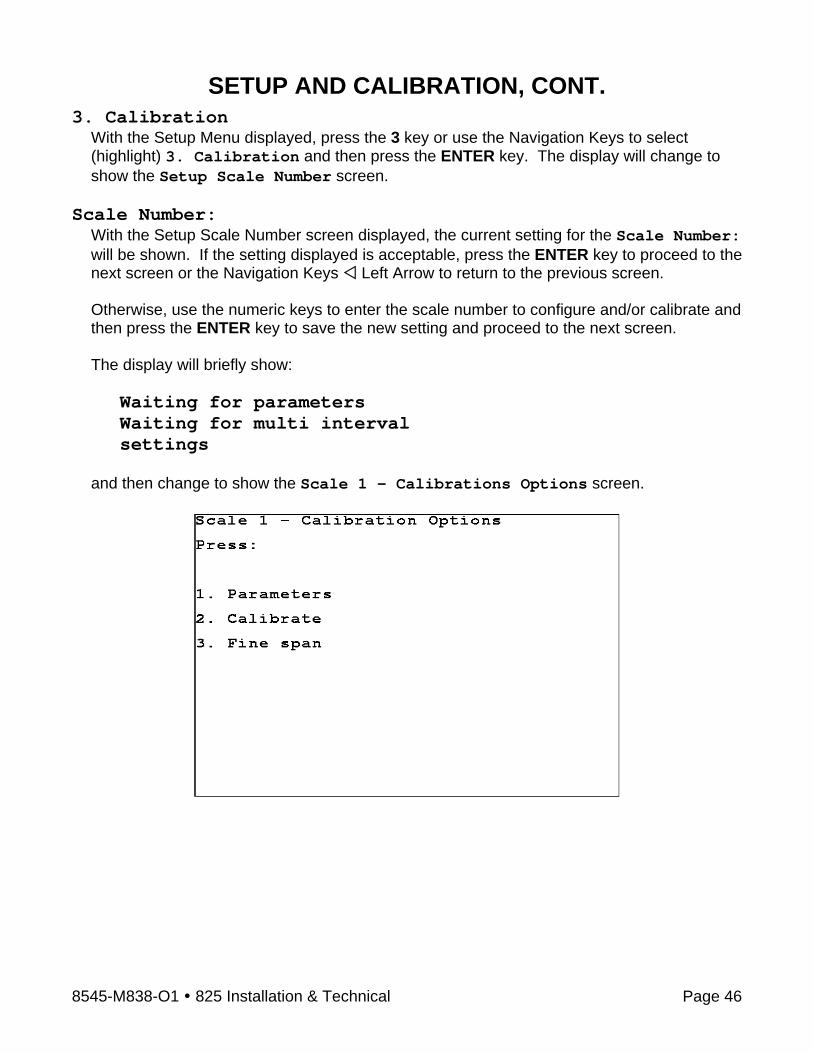
Otherwise, use the numeric keys to enter the scale number to configure and/or calibrate and then press the ENTER key to save the new setting and proceed to the next screen. The display will briefly show:
Waiting for parameters Waiting for multi interval settings
and then change to show the Scale 1 – Calibrations Options screen.
8545-M838-O1 825 Installation & Technical Page 47
SETUP AND CALIBRATION, CONT. 1. Parameters
With the Scale 1 – Calibration Options screen displayed, press the 1 key or use the Navigation Keys to select (highlight) 1. Parameters. and then press the ENTER key. The display will change to show the Scale 1 – Calibration General screen.
Scale 1 – Calibration – General Capacity:
With the Scale 1 - Calibration – General screen displayed the current setting for the Capacity: parameter will be shown. If the setting displayed is acceptable, proceed to the next parameter. Otherwise, use the numeric keys to enter the maximum weight that may be weighed on the scale and then press the Down Arrow to advance to the next parameter or press the ENTER key to save the new setting and return to the previous screen. Note that the Capacity cannot exceed 7 digits. Allowable values are 1 through 9,999,999.
Base Units: With the Scale 1 - Calibration – General screen displayed the current setting for the Base Units: parameter will be shown. If the setting displayed is acceptable, proceed to the next parameter. Otherwise, press the SPACE key to step through and select the Base Units and then press the Down Arrow to advance to the next parameter or press the ENTER key to save the new setting and return to the previous screen. Supported Base Units are:
Base Units Selections
lb (pounds) tn (tons) Custom kg (kilograms tonne (metric tons)
If Custom is selected for Base Units:, the following additional parameter will be shown (below the Base Units: parameter) and requires data to be entered. Otherwise, proceed to the Interval: parameter.
Custom Label:
With Custom selected for Base Units: the current setting for Custom label: will be shown. If the setting displayed is acceptable, proceed to the next parameter.
Otherwise, use the alpha-numeric keys to enter a new description for the Base Units Custom label (up to 4 characters, e.g., Gal. for Gallons) and then press the Down Arrow to advance to the next parameter or press the ENTER key to save the new setting and return to the previous screen.

8545-M838-O1 825 Installation & Technical Page 48
SETUP AND CALIBRATION, CONT. Interval:
With the Scale 1 - Calibration – General screen displayed the current setting for the Interval: parameter will be shown. If the setting displayed is acceptable, proceed to the next parameter. NOTE! If using multiples intervals, this is the low interval. Otherwise, use the numeric keys to enter the interval (or minimum increment of weight reading) and then press the Down Arrow to advance to the next parameter or press the ENTER key to save the new setting and return to the previous screen. Allowable values are 1, 2, 5, 10, 20, 50 or 100.
Interval Dec: With the Scale 1 - Calibration – General screen displayed the current setting for the Interval Dec: parameter will be shown. If the setting displayed is acceptable, proceed to the next parameter. Otherwise, use the numeric keys to enter the interval decimal places and then press the
Down Arrow to advance to the next parameter or press the ENTER key to save the new setting and return to the previous screen. Allowable values are 0 to 5.
0 = ####### 2 = #####.## 4 = ###.#### 1 = ######.# 3 = ####.### 5 = ##.#####
Conv Units:
With the Scale 1 - Calibration – General screen displayed the current setting for the Conv Units: parameter will be shown. If the setting displayed is acceptable, proceed to the next parameter. Otherwise, press the SPACE key to step through and select the Conv Units and then press the Down Arrow to advance to the next parameter or press the ENTER key to save the new setting and return to the previous screen. Supported Conv Units are:
Conv Units Selections
lb (pounds) tn (tons) None kg (kilograms tonne (metric tons) Custom
If Custom is selected for Conv Units:, an additional parameter (below the Conv Units: parameter) and the conversion setup screen will be shown. Otherwise, proceed to the Scale 1 - Calibration – Filtering screen.
Custom Label: With Custom selected for Conv Units: the current setting for Custom label: will be shown. If the setting displayed is acceptable, press the ENTER key to proceed to the next screen or the Navigation Keys Left Arrow to return to the previous screen. Otherwise, use the alphanumeric keys to enter a new description for the Conv Units Custom Label (up to 5 characters, e.g., Litre for Litre) and then press the ENTER key to save the new setting and proceed to the next screen.

8545-M838-O1 825 Installation & Technical Page 49
SETUP AND CALIBRATION, CONT. Scale 1 - Calibration – Conversion Conv Factor:
The Conv Factor (conversion factor) is a number that the Base Units (or Conv Units) must be multiplied by to obtain the Custom unit of measurement. For example:
Water weighs 8 lb per 1 Gallon.
To compute the conversion factor, you would divide 1 gallon by 8 pounds, with the result being 0.125.
Therefore, if the weight displayed were 27.65 lb, pressing the UNITS key would change the display to show 3.45625 gal. (27.65 x 0.125 = 3.45625). The gal. in the example stands for gallons. Refer to the Custom Label next prompt for information on entering the custom units label.
With the Scale 1 – Calibration – Conversion screen displayed the current setting for the Conv Factor: parameter will be shown. If the setting displayed is acceptable, proceed to the next parameter. Otherwise, use the numeric keys to enter the conversion factor and then press the Down Arrow to advance to the next parameter or press the ENTER key to save the new setting and return to the previous screen. Note that the conversion factor cannot exceed 7 digits (including the decimal point).
Sec Interval: With the Scale 1 – Calibration – Conversion screen displayed the current setting for the Sec Interval: parameter will be shown. If the setting displayed is acceptable, proceed to the next parameter. NOTE! If using multiples intervals, this is the low interval. Otherwise, use the numeric keys to enter the interval (or minimum increment of weight reading) and then press the Down Arrow to advance to the next parameter or press the ENTER key to save the new setting and return to the previous screen. Allowable values are 1, 2, 5, 10, 20, 50 or 100.
Sec Interval Dec: With the Scale 1 – Calibration – Conversion screen displayed the current setting for the Sec Interval Dec: parameter will be shown. If the setting displayed is acceptable, press the ENTER key to proceed to the next screen or the Navigation Keys Left Arrow to return to the previous screen. Otherwise, use the numeric keys to enter the interval decimal places and then press the ENTER key to save the new setting and proceed to the next screen. Allowable values are 0 to 5.
0 = ####### 2 = #####.## 4 = ###.#### 1 = ######.# 3 = ####.### 5 = ##.#####

8545-M838-O1 825 Installation & Technical Page 50
SETUP AND CALIBRATION, CONT. Scale 1 - Calibration – Filtering Zero Track:
With the Scale 1 – Calibration – Filtering screen displayed the current setting for the Zero Track: parameter will be shown. If the setting displayed is acceptable, proceed to the next parameter. Otherwise, press the SPACE key to step through and select the zero tracking range and then press the Down Arrow to advance to the next parameter or press the ENTER key to save the new setting and return to the previous screen. Available selections are Off, 0.5 div., 1 div., 2 div., 3 div., 4 div., 5 div., 6 div., 7 div., 8 div., and 9 div.
Motion Range: With the Scale 1 – Calibration – Filtering screen displayed the current setting for the Motion Range: parameter will be shown. If the setting displayed is acceptable, proceed to the next parameter. Otherwise, use the numeric keys to enter the motion range (the number of divisions of change permitted before indicating unstable) and then press the Down Arrow to advance to the next parameter or press the ENTER key to save the new setting and proceed to the next screen. Allowable values are 0 to 9. Note that entering zero (0) disables the motion range.
Filtering: With the Scale 1 – Calibration – Filtering screen displayed the current setting for the Filtering: parameter will be shown. If the setting displayed is acceptable, press the ENTER key to proceed to the next screen or the Navigation Keys Left Arrow to return to the previous screen. Otherwise, press the SPACE key to step through and select the digital filtering and then press the ENTER key to save the new setting and proceed to the next screen. Allowable selections are Off, Minimal, Moderate, and Custom.
Off Disabled (NO Filtering) Minimal Minimal Filtering (Sample Rate = 2) Moderate Moderate Filtering (Sample Rate = 1) Custom Custom Filtering (Additional Parameters Displayed)
IMPORTANT! When Custom Filtering (Custom) has been selected, the following parameters, Filter Value: and Filter Break: will be displayed.

8545-M838-O1 825 Installation & Technical Page 51
SETUP AND CALIBRATION, CONT. Filter Value:
With Custom selected for Filtering:, the current setting for the Filter Value: parameter will be shown on the Scale 1 – Calibration – Filtering screen. The filter value is a number from 1 to 255 that corresponds to the level of filtering with 255 being the greatest filtering and 1 the least. If the setting displayed is acceptable, proceed to the next parameter. Otherwise, use the numeric keys to enter the value for the filter value and then press the ENTER key to save the new setting and proceed to the next screen. Allowable values are 0 to 255.
Filter Break: With Custom selected for Filtering:, the current setting for the Filter Break: parameter will be shown on the Scale 1 – Calibration – Filtering screen. The filter break range is a number from 1 to 64 that corresponds to the number of division changes to break out of the filtering. If the setting displayed is acceptable, press the ENTER key to proceed to the next screen or the Navigation Keys Left Arrow to return to the previous screen. Otherwise, use the numeric keys to enter the value for filter break range and then press the Down Arrow to advance to the next parameter or press the ENTER key to save the new setting and proceed to the next screen. Allowable values are 0 to 64.

8545-M838-O1 825 Installation & Technical Page 52
SETUP AND CALIBRATION, CONT. Filter Setting Recommendations
Non-Critical Sample Rate If the sample rate is not critical, as in static weighing, set Filtering: to:
Filtering: Off (NO Filtering)
Filtering: Minimal (Filter Value: 6, Filter Break: 12, Sample Rate: 2/Sec) or
Filtering: Moderate (Filter Value: 6, Filter Break: 8, Sample Rate: 1/Sec).
Critical Sample Rate With a critical sample rate, as in a filling operation, use (Filtering: Custom).
1. Sample Rate: (1 to 200 samples/second) determination: Set the sample rate as close as possible to produce a display graduation change for every graduation of material added to the scale.
Material Flow Rate (lbs/second)Interval = Sample Rate:
100lbs/sec EXAMPLE: 10lbs = 10s/s = Sample Rate:
2. Filter Value: (0 to 255) determination: Set to desired results. 3. Filter Break: (1 to 64 graduations) determination:
Turn the filtering off by setting Filtering: Off. Operate the system as it will be normally used and, by observation, determine the number of graduations of instability that needs to be filtered out. Set the Filter Break: range to that value.
Weight Change Interval = Filter Break:
EXAMPLE: 20,000 x 10lb capacity scale with 800lb variation in the weight display.
800 10 = Filter Break: 80
4. If stability is unacceptable with any setting of Filter Value:, reduce the
Sample Rate: and/or increase the Filter Break: range setting for increased filtering.

8545-M838-O1 825 Installation & Technical Page 53
SETUP AND CALIBRATION, CONT. Scale 1 - Calibration – Options Sample Rate:
With the Scale 1 – Calibration – Options screen displayed the current setting for the Sample Rate: parameter will be shown. If the setting displayed is acceptable, proceed to the next parameter. Otherwise, use the numeric keys to enter the sample rate in samples per seconds and then press the Down Arrow to advance to the next parameter or press the ENTER key to save the new setting and proceed to the next screen. Allowable values are 1 to 200. NOTE! The Sample Rate: will automatically be set to a 2 when Minimal Filtering: has been selected, or a 1 when Moderate has been selected for Filtering:.
Num Cal Pts: Calibration of the scale can be performed using multiple calibration points to obtain a more precise weight reading over the entire span of the scale. With the Scale 1 – Calibration – Options screen displayed the current setting for the Num Cal Pts parameter will be shown. If the setting displayed is acceptable, proceed to the next parameter. Otherwise, use the numeric keys to enter the number of calibration points and then press the Down Arrow to advance to the next parameter or press the ENTER key to save the new setting and proceed to the next screen. Allowable values are 1 to 4. IMPORTANT! The Num Cal Pts parameter is used to set the calibration points in addition to the zero (no load) weight calibration point. DO NOT include the zero (no load) weight calibration point when selecting the number of calibration points. For example, selecting 2 for the Num Cal Pts parameter, you would have a total of three calibration points, the zero (no load) weight and two calibrations points that could correspond to a mid-point weight and the test (load) weight.
Totalizer: The Totalizer will sum the weights of two or more scales and make the total available to the application program. The Totalizer can be referenced as if it were another scale. With the Scale 1 – Calibration – Options screen displayed the current setting for the Totalizer: parameter will be shown. If the setting displayed is acceptable, proceed to the next parameter. Otherwise, press the SPACE key to toggle its status (select YES or NO) and then press the Down Arrow to advance to the next parameter or press the ENTER key to save the new setting and return to the previous screen. Totalizer: Yes Totalizer: No
Select Yes to Enable the Totalizer Select No to Disable the Totalizer.
8545-M838-O1 825 Installation & Technical Page 54
SETUP AND CALIBRATION, CONT. OIML:
With the Scale 1 – Calibration – Options screen displayed the current setting for the OIML: parameter will be shown. This parameter determines whether the indicator will be used in an application requiring an OIML Compliance. If the setting displayed is acceptable, press the ENTER key to proceed to the next screen or the Navigation Keys
Left Arrow to return to the previous screen. Otherwise, press the SPACE key to toggle its status (select YES or NO) and then press the ENTER key to save the new setting and proceed to the next screen. OIML: Yes OIML: No
OIML Compliance Enabled Manual Tare Entry (PT is displayed
and printed) Single Interval weight displays:
Max (Maximum Capacity) Min (Minimum Capacity) e (Scale Interval)
OIML Compliance Disabled Manual Tare Entry (MAN WT is
displayed and printed) Single Interval weight displays:
Scale Capacity and Interval
Selecting Yes meets International Organization of Legal Metrology (OIML) compliance. When YES is selected, serial port COM3 will be dedicated to outputting scale gross weight whenever the application program is executing. The application program cannot manipulate this output in any way. The serial port communications parameters will default to 9600 baud, 8 data bits, no parity bits and 1 stop bit. Note that the serial port communication parameters can be change in the Communication setup. The data will be sent out at a rate of 2 times per second.
8545-M838-O1 825 Installation & Technical Page 55
SETUP AND CALIBRATION, CONT. Scale 1 - Calibration – Other Options Zero Limit:
With the Scale 1 – Calibration – Other Options screen displayed the current setting for the Zero Limit: parameter will be shown. If the setting displayed is acceptable, proceed to the next parameter. Otherwise, press the SPACE key to toggle its status (select YES or NO) and then press the Down Arrow to advance to the next parameter or press the ENTER key to save the new setting and return to the previous screen. Zero Limit: Yes Zero Limit: No
Select Yes to limit push button zero and zero tracking to ± 2% of capacity
Full capacity (no limit on push button zero and zero tracking)
USA:
With the Scale 1 – Calibration – Other Options screen displayed the current setting for the USA: parameter will be shown. This parameter selects whether the indicator is used in the USA (domestic) or outside the USA (international). If the setting displayed is acceptable, proceed to the next parameter. Otherwise, press the SPACE key to toggle its status (select YES or NO) and then press the Down Arrow to advance to the next parameter or press the ENTER key to save the new setting and return to the previous screen.
USA: YES USA: NO
OC = 104% of scale capacity OC = scale capacity + 9 grads 2nd Order Lin:
With the Scale 1 – Calibration – Other Options screen displayed the current setting for the 2nd Order Lin: parameter will be shown. 2nd Order Linearization is a method used to correct for nonlinearity in the load cell signal. An extra term, which is proportional to the square of the load cell signal, is used in the conversion of load cell signal into a weight value. If the setting displayed is acceptable, press the ENTER key to proceed to the next screen or the Navigation Keys Left Arrow to return to the previous screen. Otherwise, press the SPACE key to toggle its status (select YES or NO) and then press the ENTER key to save the new setting and proceed to the next screen. 2nd Order Lin: Yes 2nd Order Lin: No
2nd Order Linearization is Enable. The COEFF option will be added to Fine Span screen.
2nd Order Linearization is Disabled.Fine Span screen contains only Up, Down, Zero and Quit options.
IMPORTANT! In order for 2nd Order Linearization to take effect, calibration must be performed with at least a total of three calibration points (no load and two load points with different weights). If only two calibration points (no load and load) are used, the COEFF option will NOT be added to the Fine Span screen.

8545-M838-O1 825 Installation & Technical Page 56
SETUP AND CALIBRATION, CONT. Scale 1 - Calibration – Multi Interval Intervals:
With the Scale 1 – Calibration – Multi Interval screen displayed the current setting for the Intervals: parameter will be shown. If the setting displayed is acceptable, proceed to the next parameter. Otherwise, press the SPACE key to step through and select the Interval (number of weight ranges to use). Allowable selections are One, Two, or Three.
One Select One for Single Interval and then press the ENTER key to save the new setting and proceed to the Calibrate Scale screen. After pressing the ENTER key, the display will briefly show: Setting Parameters and then Setting Multi-Interval
and then change to the Calibrate Scale screen.
Two If Two is selected, two (2) additional parameters will be displayed on the screen. Press the Down Arrow to advance to the;
Low Interval Capacity: This is the weight capacity for the low range interval. If the setting displayed is acceptable, press the Down Arrow to advance to the Middle Interval Value:. Otherwise, use the numeric keys to enter the weight capacity for the low range interval and then press the Down Arrow to advance to the next parameter. Note that the value entered cannot exceed 7 digits and must be less than the overall capacity.
Middle Interval Value:. This is the middle range interval value. If the setting displayed is acceptable, press the ENTER key to save the setting and proceed to the Calibrate Scale screen. Otherwise, use the numeric keys to enter the middle interval weight increment value (the value entered must be bigger than the low interval value) and then press the ENTER key to save the new setting. In either case, after pressing the ENTER key, the display will briefly show: Setting Parameters and then Setting Multi-Interval
and then change to the Calibrate Scale screen.
IMPORTANT! The error message Invalid two interval settings will be displayed after pressing the ENTER key, if incorrect values have been entered for Low Interval Capacity: and Middle Interval Value:. To change the settings, press the ←⎯ /ESC key to return to the Intervals: screen.

8545-M838-O1 825 Installation & Technical Page 57
SETUP AND CALIBRATION, CONT. Intervals: Three
If Three is selected, four (4) additional parameters will be displayed on the screen. Press the Down Arrow to advance to the;
Low Interval Capacity:
This is the weight capacity for the low range interval. If the setting displayed is acceptable, press the Down Arrow to advance to Middle Interval Value:. Otherwise, use the numeric keys to enter the weight capacity for the low range interval and then press the Down Arrow to advance to the next parameter. Note that the value entered cannot exceed 7 digits and must be less than the overall scale capacity.
Middle Interval Value:. This is the middle range interval value. If the setting displayed is acceptable, press the
Down Arrow to advance to the Middle Interval Capacity:. Otherwise, use the numeric keys to enter the middle interval weight increment value and then press the Down Arrow to advance to the next parameter. Note that the value entered must be bigger than the low interval value.
Middle Interval Capacity: This is the weight capacity for the middle range interval. If the setting displayed is acceptable, press the Down Arrow to advance to the High Interval Value:. Otherwise, use the numeric keys to enter the weight capacity for the middle range interval and then press the Down Arrow to advance to the next parameter. Note that the value entered cannot exceed 7 digits and must be less than the overall capacity and greater than the low capacity.
High Interval Value: This is the middle range interval value. If the setting displayed is acceptable, press the ENTER key to save the setting and proceed to the Calibrate Scale screen. Otherwise, use the numeric keys to enter the high interval weight increment value (the value entered must be bigger than the middle interval value) and then press the ENTER key to save the new setting and proceed to the Calibrate Scale screen. In either case, after pressing the ENTER key, the display will briefly show: Setting Parameters and then Setting Multi-Interval
and then change to the Calibrate Scale screen.
IMPORTANT! The error message Invalid three interval settings will be displayed after pressing the ENTER key, if incorrect values have been entered for Low Interval Capacity:, Middle Interval Value:, Middle Interval Capacity: and High Interval Value:. To change the settings, press the ←⎯ /ESC key to return to the Intervals: screen.
8545-M838-O1 825 Installation & Technical Page 58
SETUP AND CALIBRATION, CONT. Calibration Methods The 825 has two methods to enter the calibration procedure. One method is performed after entering the calibration setup parameters. The other method is selected from the Setup Menu screen and skips entering the calibration setup parameters. Calibration of the scale can be performed using up to four calibration points in addition to the zero (no load) weight. The number of calibration points is determined by the Num Cal Pts parameter. When one point is used, only screen prompts for Weight 1 and Weight 2 will be displayed. If more than one point is used, additional screen prompts for Weight 3, Weight 4 and Weight 5 will be displayed. Note that one weighing must be zero (no load) weight. The following examples use two calibration points in addition to the zero (no load) weight. The two points could correspond to a mid-point weight and the test (load) weight. Calibration after Entering Parameters
1. With the Calibrate Scale screen displayed, the current setting Calibrate: NO will be shown. If calibration is desired, press the SPACE key to toggle its status from No to Yes and then press the ENTER key to proceed with calibration. Otherwise, press the ENTER key to return to the Scale 1 – Calibration Options screen.
2. The display will change to show the Scale 1 – Calibration Weight 1 screen.
3. If this is the zero weight (no load), press the 0 key and then press the ENTER key. Otherwise, place the weights on the scale and then using the numeric keys, enter the current weight on the scale and then press the ENTER key.
4. The display will show the percentage of completion and a dashed line proceeding from left to right for this step. When this step has been completed, the display will change to show the Scale 1 – Calibration Weight 2 screen.
5. If this is the zero weight (no load), press the 0 key and then press the ENTER key. Otherwise, place the weights on the scale and then using the numeric keys, enter the current weight on the scale and then press the ENTER key.
6. The display will show the percentage of completion and a dashed line proceeding from left to right for this step. When this step has been completed, the display will change to change to show the Scale 1 – Calibration Weight 3 screen.
7. If this is the zero weight (no load), press the 0 key and then press the ENTER key. Otherwise, place the weights on the scale and then using the numeric keys, enter the current weight on the scale and then press the ENTER key.
8. The display will show the percentage of completion and a dashed line proceeding from left to right for this step. When this step has been completed, the display will change to show the Scale 1 – Fine Span screen. NOTE! If Span Adjustment is required, proceed to the FINE SPAN ADJUSTMENT.
8545-M838-O1 825 Installation & Technical Page 59
SETUP AND CALIBRATION, CONT. Calibration from the Setup Menu
1. From the Startup screen, press the 3 key or use the Navigation Keys to select (highlight) Setup menu option and then press the ENTER key.
2. Enter the Login and Password if the Login screen is displayed.
3. From the Setup Menu, press the 3 key or use the Navigation Keys to select (highlight) 3. Calibration and then press the ENTER key.
4. With the Setup Scale Number screen displayed, verify the correct scale number is shown and then press the ENTER key. Otherwise, use the numeric keys to enter the scale number and then press the ENTER key.
5. The display will change to show the Scale 1 – Calibration Weight 1 screen.
6. If this is the zero weight (no load), press the 0 key and then press the ENTER key. Otherwise, place the weights on the scale and then using the numeric keys, enter the current weight on the scale and then press the ENTER key.
7. The display will show the percentage of completion and a dashed line proceeding from left to right for this step. When this step has been completed, the display will change to show the Scale 1 – Calibration Weight 2 screen.
8. If this is the zero weight (no load), press the 0 key and then press the ENTER key. Otherwise, place the weights on the scale and then using the numeric keys, enter the current weight on the scale and then press the ENTER key.
9. The display will show the percentage of completion and a dashed line proceeding from left to right for this step. When this step has been completed, the display will change to change to show the Scale 1 – Calibration Weight 3 screen.
10. If this is the zero weight (no load), press the 0 key and then press the ENTER key. Otherwise, place the weights on the scale and then using the numeric keys, enter the current weight on the scale and then press the ENTER key.
11. The display will show the percentage of completion and a dashed line proceeding from left to right for this step. When this step has been completed, the display will change to show the Scale 1 – Fine Span screen. NOTE! If Span Adjustment is required, proceed to the FINE SPAN ADJUSTMENT.
8545-M838-O1 825 Installation & Technical Page 60
SETUP AND CALIBRATION, CONT. Scale 1 – Fine Span
If Fine Span adjustment is desired, with the Scale 1 – Fine Span screen displayed, place a calibrated test weight on the scale.
Use the Navigation Keys to select (highlight) the Fine Span adjustment option and then press the ENTER key to perform the function or;
Press the U key to increase displayed weight. Press the D key to decrease the displayed weight, Press the Z key to zero the scale. Press the Q key to save the current settings and Quit. The display will return to the
Scale 1 – Calibration Options screen.
If 2nd Order Linearization was enabled and the Num Cal Pts parameter is set for 2 or more, then a COEFF option will be added to the Fine Span screen. This option is used to make adjustments to the displayed weight after linearization testing has shown an error in a specific range of weight. Press the C key or use the Navigation Keys to select (highlight) the Coeff option and then press the ENTER key to proceed to the Coefficient screen.
Linear Coefficient:
The Linear Coefficient is applied to the load cell signal to calculate weight. If the current setting displayed for this coefficient is acceptable, press the Down Arrow to advance to the 2nd Order Coeff: parameter. Otherwise, use the numeric keys to enter a new Linear Coefficient and then press the Down Arrow to advance to the next parameter.
2nd Order Coeff: This coefficient is applied to the square of the load cell signal to calculate weight. If the current 2nd Order Coeff setting displayed is acceptable, press the Down Arrow to advance to the Tweak low weight: parameter. Otherwise, use the numeric keys to enter a new 2nd Order Coeff and then press the Down Arrow to advance to the next parameter.
WARNING! Changing the Linear Coefficient or the 2nd Order Coeff will affect the indicator's ability to display the proper weight. Please consult the factory before making any changes.

8545-M838-O1 825 Installation & Technical Page 61
SETUP AND CALIBRATION, CONT. Tweak low weight:
This is the low end of the range of weight that requires adjusting. For example, if after performing linearization testing, the displayed weight is 5 lbs low between 10,000 lbs and 15,000 lbs, the value for the tweak low weight is 10000. If the setting displayed is acceptable, press the Down Arrow to advance to the Tweak high weight: parameter. Otherwise, use the numeric keys to enter the tweak low weight and then press the Down Arrow to advance to the next parameter.
Tweak high weight: This is the high end of the range of weight that requires adjusting. Using the example above, the value for the tweak high weight is 15000. If the setting displayed is acceptable, press the Down Arrow to advance to the Tweak weight: parameter. Otherwise, use the numeric keys to enter the tweak high weight and then press the Down Arrow to advance to the next parameter.
Tweak weight: This is the amount of weight that needs to be added (or subtracted) from the range of weight to bring the displayed weight into tolerance. Again, using the example above, the Tweak Weight would be 5. If the setting displayed is acceptable, press the ENTER key to return to the Scale 1 – Fine Span screen. Otherwise, use the numeric keys to enter a new tweak weight and then press the ENTER key to return to the Scale 1 – Fine Span screen.

8545-M838-O1 825 Installation & Technical Page 62
PREFERENCES 1. Press the ON/OFF key to turn on the 825. The display will perform a short self-test and
then change to the Startup screen showing the software versions and diagnostics of the option cards.
2. Press the Navigation Keys Down Arrow to “advance” to (highlight) the Setup menu option and then press the ENTER key or press the 3 key to select the Setup menu option. The display will change to show the Setup Menu screen.
IMPORTANT! If the Login and Password protection feature has been enable, the Login screen will be displayed instead of the Setup Menu screen. Enter the login and then press the Down Arrow to advance to the password prompt. Enter the password and then press the ENTER key to proceed to the Setup Menu.
3. With the Setup Menu displayed, press the 5 key or use the Navigation Keys to select (highlight) 5. Preferences and then press the ENTER key. The display will change to show the Preferences Menu screen.
1. Date/Time
With the Preferences Menu displayed, press the 1 key or use the Navigation Keys to select (highlight) 1. Date/Time and then press the ENTER key. The display will change to show the Setup Preferences screen for the Date and Time.
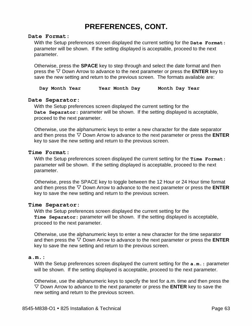
8545-M838-O1 825 Installation & Technical Page 63
PREFERENCES, CONT. Date Format:
With the Setup preferences screen displayed the current setting for the Date Format: parameter will be shown. If the setting displayed is acceptable, proceed to the next parameter.
Otherwise, press the SPACE key to step through and select the date format and then press the Down Arrow to advance to the next parameter or press the ENTER key to save the new setting and return to the previous screen. The formats available are:
Day Month Year Year Month Day Month Day Year
Date Separator:
With the Setup preferences screen displayed the current setting for the Date Separator: parameter will be shown. If the setting displayed is acceptable, proceed to the next parameter. Otherwise, use the alphanumeric keys to enter a new character for the date separator and then press the Down Arrow to advance to the next parameter or press the ENTER key to save the new setting and return to the previous screen.
Time Format: With the Setup preferences screen displayed the current setting for the Time Format: parameter will be shown. If the setting displayed is acceptable, proceed to the next parameter.
Otherwise, press the SPACE key to toggle between the 12 Hour or 24 Hour time format and then press the Down Arrow to advance to the next parameter or press the ENTER key to save the new setting and return to the previous screen.
Time Separator: With the Setup preferences screen displayed the current setting for the Time Separator: parameter will be shown. If the setting displayed is acceptable, proceed to the next parameter. Otherwise, use the alphanumeric keys to enter a new character for the time separator and then press the Down Arrow to advance to the next parameter or press the ENTER key to save the new setting and return to the previous screen.
a.m.: With the Setup preferences screen displayed the current setting for the a.m.: parameter will be shown. If the setting displayed is acceptable, proceed to the next parameter. Otherwise, use the alphanumeric keys to specify the text for a.m. time and then press the
Down Arrow to advance to the next parameter or press the ENTER key to save the new setting and return to the previous screen.

8545-M838-O1 825 Installation & Technical Page 64
PREFERENCES, CONT. p.m.:
With the Setup preferences screen displayed the current setting for the p.m.: parameter will be shown. If the setting displayed is acceptable, press the ENTER key or the Navigation Keys Left Arrow to return to the previous screen. Otherwise, use the alphanumeric keys to specify the text for p.m. time and then press the ENTER key to save the new setting and return to the previous screen.
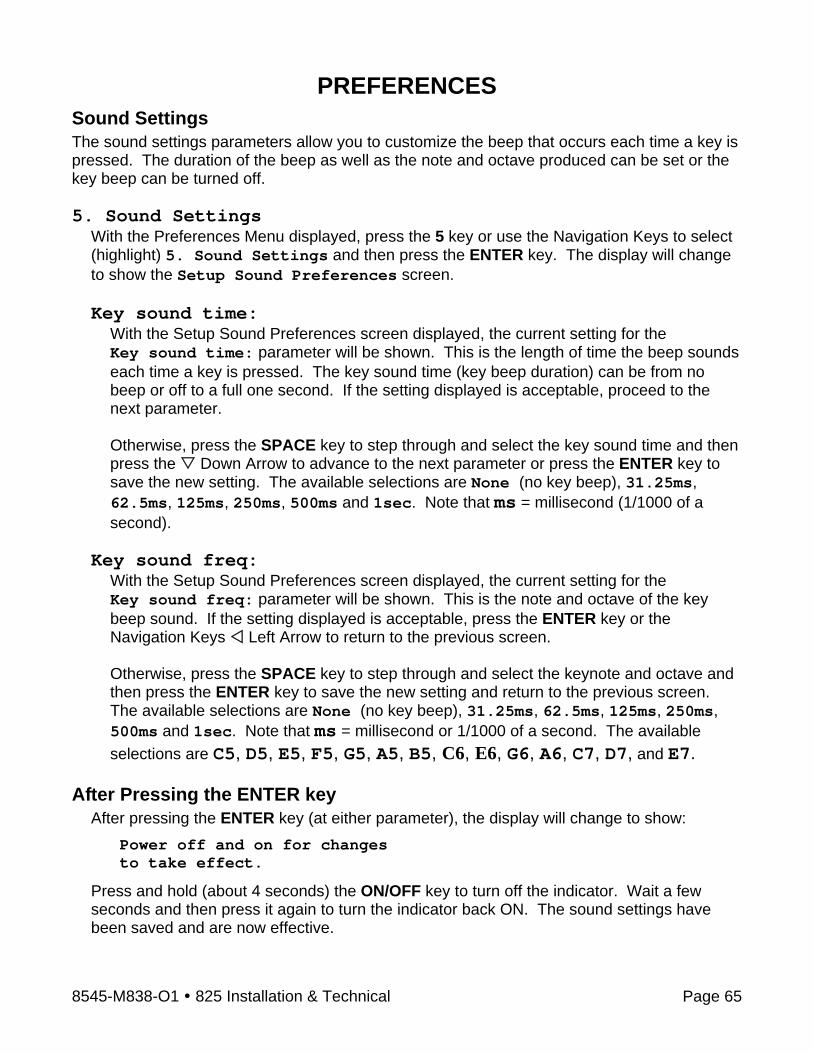
8545-M838-O1 825 Installation & Technical Page 65
PREFERENCES Sound Settings The sound settings parameters allow you to customize the beep that occurs each time a key is pressed. The duration of the beep as well as the note and octave produced can be set or the key beep can be turned off. 5. Sound Settings
With the Preferences Menu displayed, press the 5 key or use the Navigation Keys to select (highlight) 5. Sound Settings and then press the ENTER key. The display will change to show the Setup Sound Preferences screen. Key sound time:
With the Setup Sound Preferences screen displayed, the current setting for the Key sound time: parameter will be shown. This is the length of time the beep sounds each time a key is pressed. The key sound time (key beep duration) can be from no beep or off to a full one second. If the setting displayed is acceptable, proceed to the next parameter.
Otherwise, press the SPACE key to step through and select the key sound time and then press the Down Arrow to advance to the next parameter or press the ENTER key to save the new setting. The available selections are None (no key beep), 31.25ms, 62.5ms, 125ms, 250ms, 500ms and 1sec. Note that ms = millisecond (1/1000 of a second).
Key sound freq: With the Setup Sound Preferences screen displayed, the current setting for the Key sound freq: parameter will be shown. This is the note and octave of the key beep sound. If the setting displayed is acceptable, press the ENTER key or the Navigation Keys Left Arrow to return to the previous screen. Otherwise, press the SPACE key to step through and select the keynote and octave and then press the ENTER key to save the new setting and return to the previous screen. The available selections are None (no key beep), 31.25ms, 62.5ms, 125ms, 250ms, 500ms and 1sec. Note that ms = millisecond or 1/1000 of a second. The available selections are C5, D5, E5, F5, G5, A5, B5, C6, E6, G6, A6, C7, D7, and E7.
After Pressing the ENTER key
After pressing the ENTER key (at either parameter), the display will change to show:
Power off and on for changes to take effect.
Press and hold (about 4 seconds) the ON/OFF key to turn off the indicator. Wait a few seconds and then press it again to turn the indicator back ON. The sound settings have been saved and are now effective.

8545-M838-O1 825 Installation & Technical Page 66
OPERATORS The Model 825 supports up to eight operators. One operator, the Administrator has full access to all functions and features of the 825. The remaining seven can be configured to allow or prevent access to various functions and features. Note that only the login name and password can be changed for the Administrator operator. 1. Press the ON/OFF key to apply power to the 825. The display will perform a short self-test
and then change to the Startup screen showing the software versions and diagnostics of the option cards.
2. Press the Navigation Keys Down Arrow to “advance” to (highlight) the Setup menu option and then press the ENTER key or press the 3 key to select the Setup menu option. The display will change to show the Setup Menu screen.
IMPORTANT! If the Login and Password protection feature has been enable, the Login screen will be displayed instead of the Setup Menu screen. Enter the login (ADMIN) and then press the Down Arrow to advance to the password prompt. Enter the password and then press the ENTER key to proceed to the Setup Menu.
3. With the Setup Menu displayed, press the 8 key or use the Navigation Keys to select (highlight) 8. Operators and then press the ENTER key. The display will change to show the Setup Operators screen.
1. List Operators
1. With the Setup Operators screen displayed, press the 1 key or use the Navigation Keys to select (highlight) 1. List Operators and then press the ENTER key.
2. The display will change to show the Operator List screen for the current programmed operators.
3. After viewing the list, press any key to return to the Setup Operators screen.
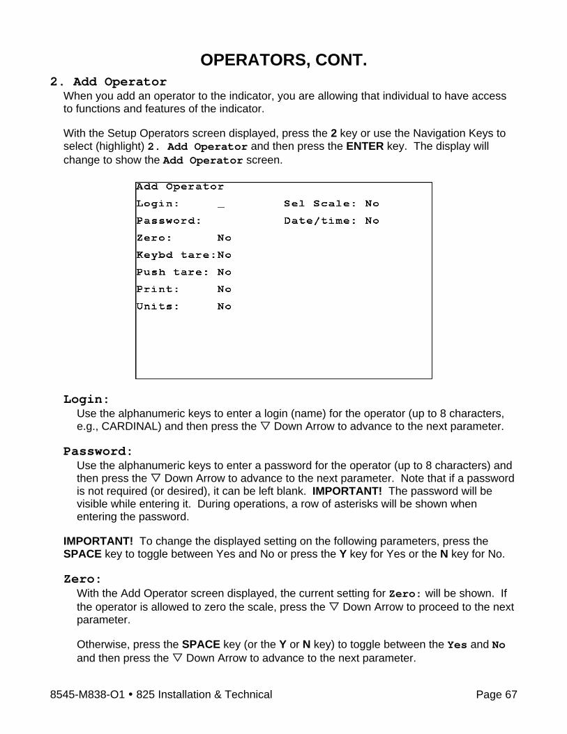
8545-M838-O1 825 Installation & Technical Page 67
OPERATORS, CONT. 2. Add Operator
When you add an operator to the indicator, you are allowing that individual to have access to functions and features of the indicator. With the Setup Operators screen displayed, press the 2 key or use the Navigation Keys to select (highlight) 2. Add Operator and then press the ENTER key. The display will change to show the Add Operator screen.
Login:
Use the alphanumeric keys to enter a login (name) for the operator (up to 8 characters, e.g., CARDINAL) and then press the Down Arrow to advance to the next parameter.
Password:
Use the alphanumeric keys to enter a password for the operator (up to 8 characters) and then press the Down Arrow to advance to the next parameter. Note that if a password is not required (or desired), it can be left blank. IMPORTANT! The password will be visible while entering it. During operations, a row of asterisks will be shown when entering the password.
IMPORTANT! To change the displayed setting on the following parameters, press the SPACE key to toggle between Yes and No or press the Y key for Yes or the N key for No.
Zero:
With the Add Operator screen displayed, the current setting for Zero: will be shown. If the operator is allowed to zero the scale, press the Down Arrow to proceed to the next parameter. Otherwise, press the SPACE key (or the Y or N key) to toggle between the Yes and No and then press the Down Arrow to advance to the next parameter.

8545-M838-O1 825 Installation & Technical Page 68
OPERATORS, CONT. Keybd tare:
With the Add Operator screen displayed, the current setting for Keybd tare: will be shown. If the operator is allowed to manually enter a tare weight, press the Down Arrow to proceed to the next parameter. Otherwise, press the SPACE key (or the Y or N key) to toggle between the Yes and No and then press the Down Arrow to advance to the next parameter.
Push tare: With the Add Operator screen displayed, the current setting for Push tare: will be shown. If the operator is allowed to use the Push Button tare function to enter a tare weight, press the Down Arrow to proceed to the next parameter. Otherwise, press the SPACE key (or the Y or N key) to toggle between the Yes and No and then press the Down Arrow to advance to the next parameter.
Print: With the Add Operator screen displayed, the current setting for Print: will be shown. If the operator is allowed to print a ticket, press the Down Arrow to proceed to the next parameter. Otherwise, press the SPACE key (or the Y or N key) to toggle between the Yes and No and then press the Down Arrow to advance to the next parameter.
Units: With the Add Operator screen displayed, the current setting for Units: will be shown. If the operator is allowed to select the alternate weighing units, press the Down Arrow to proceed to the next parameter. Otherwise, press the SPACE key (or the Y or N key) to toggle between the Yes and No and then press the Down Arrow to advance to the next parameter.
Sel Scale: With the Add Operator screen displayed, the current setting for Sel Scale: will be shown. In a multiple scale operation, if the operator is allowed to choose between available scales, press the Down Arrow to proceed to the next parameter. Otherwise, press the SPACE key (or the Y or N key) to toggle between the Yes and No and then press the Down Arrow to advance to the next parameter.
Date/Time: With the Add Operator screen displayed, the current setting for Date/Time: will be shown. If the operator is allowed to change the date and time, press the ENTER key to save the settings and return to the previous screen. Otherwise, press the SPACE key (or the Y or N key) to toggle between the Yes and No and then press the ENTER key to save the settings and return to the previous screen.
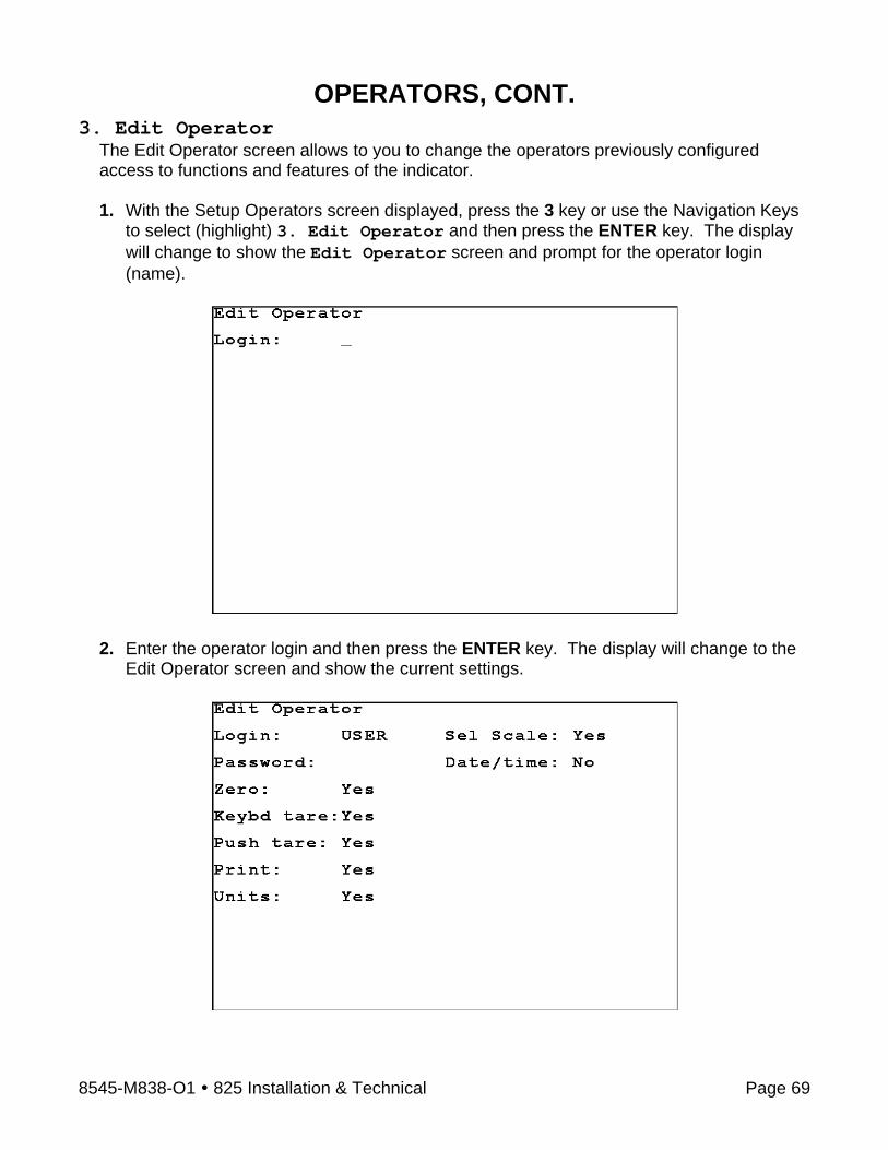
8545-M838-O1 825 Installation & Technical Page 69
OPERATORS, CONT. 3. Edit Operator
The Edit Operator screen allows to you to change the operators previously configured access to functions and features of the indicator. 1. With the Setup Operators screen displayed, press the 3 key or use the Navigation Keys
to select (highlight) 3. Edit Operator and then press the ENTER key. The display will change to show the Edit Operator screen and prompt for the operator login (name).
2. Enter the operator login and then press the ENTER key. The display will change to the
Edit Operator screen and show the current settings.
8545-M838-O1 825 Installation & Technical Page 70
OPERATORS, CONT. Login:
With the Edit Operator screen displayed, the current login (name) will be shown. If the login displayed is acceptable, proceed to the next parameter. Otherwise, use the alphanumeric keys to enter a new login for the operator (up to 8 characters) and then press the Down Arrow to advance to the next parameter.
IMPORTANT! Changing the login REPLACES the current login. It DOES NOT create a new login in addition to existing login. It will however, retain the settings from the old login for the new login (e.g., Zero: Yes, Keybd tare: No, etc...).
Password:
With the Edit Operator screen displayed, the current password will be shown. If the password displayed is acceptable, proceed to the next parameter. Otherwise, use the alphanumeric keys to enter a new password for the operator (up to 8 characters) and then press the Down Arrow to advance to the next parameter. Note that if a password is not required (or desired), it can be left blank. IMPORTANT! The password will be visible while entering it. During operations, a row of asterisks will be shown when entering the password.
IMPORTANT! To change the displayed setting on the following parameters, press the SPACE key to toggle between Yes and No or press the Y key for Yes or the N key for No.
Zero:
With the Edit Operator screen displayed, the current setting for Zero: will be shown. If the setting displayed is acceptable, proceed to the next parameter. Otherwise, press the SPACE key (or the Y or N key) to toggle between the Yes and No and then press the Down Arrow to advance to the next parameter.
Keybd tare: With the Edit Operator screen displayed, the current setting for Keybd tare: will be shown. If the setting displayed is acceptable, proceed to the next parameter. Otherwise, press the SPACE key (or the Y or N key) to toggle between the Yes and No and then press the Down Arrow to advance to the next parameter.
Push tare: With the Edit Operator screen displayed, the current setting for Push tare: will be shown. If the setting displayed is acceptable, proceed to the next parameter. Otherwise, press the SPACE key (or the Y or N key) to toggle between the Yes and No and then press the Down Arrow to advance to the next parameter.

8545-M838-O1 825 Installation & Technical Page 71
OPERATORS, CONT. Print:
With the Edit Operator screen displayed, the current setting for Print: will be shown. If the setting displayed is acceptable, proceed to the next parameter. Otherwise, press the SPACE key (or the Y or N key) to toggle between the Yes and No and then press the Down Arrow to advance to the next parameter.
Units: With the Edit Operator screen displayed, the current setting for Units: will be shown. If the setting displayed is acceptable, proceed to the next parameter. Otherwise, press the SPACE key (or the Y or N key) to toggle between the Yes and No and then press the Down Arrow to advance to the next parameter.
Sel Scale: With the Edit Operator screen displayed, the current setting for Sel Scale: will be shown. If the setting displayed is acceptable, proceed to the next parameter. Otherwise, press the SPACE key (or the Y or N key) to toggle between the Yes and No and then press the Down Arrow to advance to the next parameter.
Date/Time: With the Edit Operator screen displayed, the current setting for Date/Time: will be shown. If the setting displayed is acceptable, proceed to the next parameter. Otherwise, press the SPACE key (or the Y or N key) to toggle between the Yes and No and then press the ENTER key to save the settings and return to the previous screen.

8545-M838-O1 825 Installation & Technical Page 72
OPERATORS, CONT. 4. Delete Operator
The Delete Operator screen allows you to delete (remove) an operator login and all previously configured settings for that login. 1. With the Setup Operators screen displayed, press the 4 key or use the Navigation Keys
to select (highlight) 4. Delete Operator and then press the ENTER key. The display will change to show the Delete Operator screen and prompt for the operator login (name).
2. Enter the operator login and then press the ENTER key. 3. The display will change to show
Are you sure?
4. To delete the login, press the Y key (for Yes) and then press the ENTER key. 5. The display will change to show the Setup Operators screen. All settings for that
operator login have been deleted. 6. Otherwise, press the N key (for No) and then press the ENTER key to return to the
Setup Operators screen.

8545-M838-O1 825 Installation & Technical Page 73
OPERATORS, CONT. 5. Set Default Operator
The Set Default Operator screen allows to you to select which operator login the 825 will use when it is first turned on. With the Setup Operators screen displayed, press the 5 key or use the Navigation Keys to select (highlight) 5. Set Default Operator and then press the ENTER key. The display will change to show the Set Default Operator screen and the current default operator login (name).
Default Login:
With the Set Default Operator screen displayed, the current login (name) will be shown. If the login displayed is acceptable, press the ENTER key to return to the Setup Operators screen. Otherwise, use the alphanumeric keys to enter a new login for the default operator login and then press the ENTER key to return to the Setup Operators screen.

8545-M838-O1 825 Installation & Technical Page 74
CONFIGURATION Configuration is used to: Calibrate the touch screen, Show the touch screen tracking (a target, the “ ” sign will appear where the screen is touched), Set the color settings, to Configure the weight server (the TCP/IP server and the serial ports) and to view the Electronic Talley Roll. To Begin Configuration
1. Press the ON/OFF key to apply power to the 825. The display will perform a short self-test and then change to the Startup screen showing the software versions and diagnostics of the option cards.
2. When the 825 is initially started, a countdown staring at 7 seconds will appear to the right of 1. Application Program. Allow the countdown to complete or press the ENTER key or press the 1 key to select the Application Program option. The display will change to show:
Starting application mode
and then change to show:
Cardinal 825-loading...
Starting...
and then change to show the Application Menu.
IMPORTANT! The Application Menu screen may consist of more than one screen. Press the NEXT >>> key to view additional selections. Press the <<< Prev key to return to the first screen.
Configuration
3. With the Application Menu displayed, press the 6 key or use the Navigation Keys to select (highlight) 6 Configuration and then press the ENTER key. The display will change to show the Configuration screen.
Application Menu ver 1.09
1. Truck Storage
2. Digital Fill Control
3. Checkweigher
4. 788 Compatibility
5.
6. Configuration
Next >>>
IP: 90.1.2.165
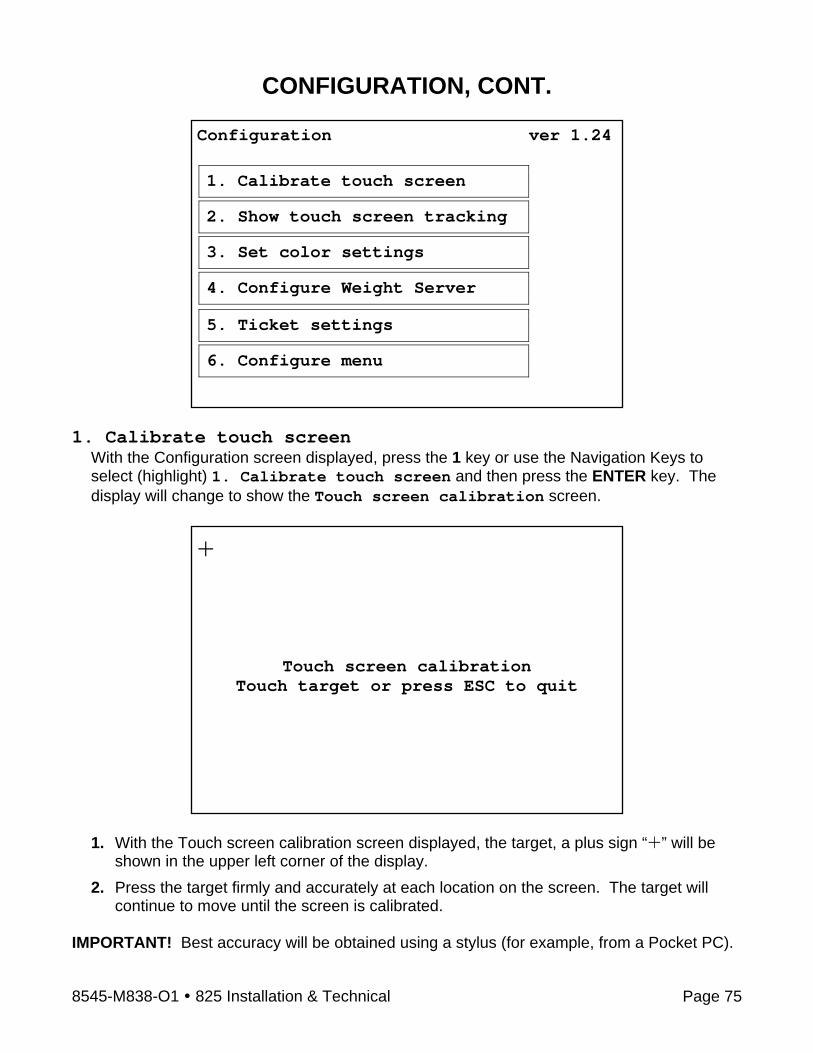
8545-M838-O1 825 Installation & Technical Page 75
CONFIGURATION, CONT.
1. Calibrate touch screen
With the Configuration screen displayed, press the 1 key or use the Navigation Keys to select (highlight) 1. Calibrate touch screen and then press the ENTER key. The display will change to show the Touch screen calibration screen.
1. With the Touch screen calibration screen displayed, the target, a plus sign “ ” will be
shown in the upper left corner of the display. 2. Press the target firmly and accurately at each location on the screen. The target will
continue to move until the screen is calibrated. IMPORTANT! Best accuracy will be obtained using a stylus (for example, from a Pocket PC).
Configuration ver 1.24
1. Calibrate touch screen
2. Show touch screen tracking
3. Set color settings
4. Configure Weight Server
5. Ticket settings
6. Configure menu
+
Touch screen calibration
Touch target or press ESC to quit

8545-M838-O1 825 Installation & Technical Page 76
CONFIGURATION, CONT. 2. Show touch screen tracking
With the Configuration screen displayed, press the 2 key or use the Navigation Keys to select (highlight) 2. Show touch screen tracking and then press the ENTER key. The display will change to show a tracking screen. Note that the screen will be blank except for a message (Press [ESC] exit) at the top center of the display.
1. With the blank tracking screen displayed, touch the screen in several locations. 2. The target, a plus sign “ ” will move to each location touched.
3. After checking several locations on the screen, press the ESC key to return to the
Configuration screen.
Press [ESC] exit
Press [ESC] exit
The sign indicates the screen was
touched here
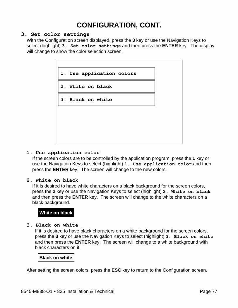
8545-M838-O1 825 Installation & Technical Page 77
CONFIGURATION, CONT. 3. Set color settings
With the Configuration screen displayed, press the 3 key or use the Navigation Keys to select (highlight) 3. Set color settings and then press the ENTER key. The display will change to show the color selection screen.
1. Use application color
If the screen colors are to be controlled by the application program, press the 1 key or use the Navigation Keys to select (highlight) 1. Use application color and then press the ENTER key. The screen will change to the new colors.
2. White on black
If it is desired to have white characters on a black background for the screen colors, press the 2 key or use the Navigation Keys to select (highlight) 2. White on black and then press the ENTER key. The screen will change to the white characters on a black background.
3. Black on white
If it is desired to have black characters on a white background for the screen colors, press the 3 key or use the Navigation Keys to select (highlight) 3. Black on white and then press the ENTER key. The screen will change to a white background with black characters on it.
After setting the screen colors, press the ESC key to return to the Configuration screen.
1. Use application colors
2. White on black
3. Black on white
Black on white
White on black

8545-M838-O1 825 Installation & Technical Page 78
CONFIGURATION, CONT. 4. Configure Weight Server
With the Configuration screen displayed, press the 4 key or use the Navigation Keys to select (highlight) 4. Configure Weight Server and then press the ENTER key. The display will change to show the Configure Weight Server screen.
1. Configure TCP/IP Server
With the Configure Weight Server screen displayed, press the 1 key or use the Navigation Keys to select (highlight) 1. Configure TCP/IP Server and then press the ENTER key. The display will change to show the Select TCP/IP Server screen.
Configure Weight Server
1. Configure TCP/IP Server
2. Configure Serial Ports
3. Electronic Talley Roll
Select TCP/IP ServerNum Sc Type Port
1. 0 Custom 1100
2. 1 On Demand 1101
** Add Server **

8545-M838-O1 825 Installation & Technical Page 79
CONFIGURATION, CONT. Select TCP/IP Server
With the Select TCP/IP Server screen displayed, press the 1 key or use the Navigation Keys to select (highlight) and then press the ENTER key to select Num 1. The display will change to show the Setup TCP/IP Server 1 screen.
Setup TCP/IP Server 1 Enable:
With the Select TCP/IP Server 1 screen displayed, the current setting for the Enable: parameter will be shown. If the setting displayed is acceptable, proceed to the next parameter. Otherwise, press the SPACE key to toggle its status. Select YES* to enable TCP/IP Server 1 or NO to disable TCP/IP Server 1 and then press the Down Arrow to advance to the next parameter or press the ENTER key to save the new setting and return to the previous screen.
If Yes is selected for Enable:, the following additional parameters will be shown (below the Enable: parameter) and requires data to be entered. Otherwise, press the ENTER key to return to the Select TCP/IP Server screen.
Port:
With the Select TCP/IP Server 1 screen displayed, the current setting for the Port: parameter will be shown. If the setting displayed is acceptable, proceed to the next parameter. Otherwise, use the numeric keys to enter the TCP/IP port number and then press the Down Arrow to advance to the next parameter or press the ENTER key to save the new setting and return to the previous screen.
Scale: With the Select TCP/IP Server 1 screen displayed, the current setting for the Scale: parameter will be shown. If the setting displayed is acceptable, proceed to the next parameter. Otherwise, use the numeric keys to enter the scale number for the server to use and then press the Down Arrow to advance to the next parameter or press the ENTER key to save the new setting and return to the previous screen.
8545-M838-O1 825 Installation & Technical Page 80
CONFIGURATION, CONT. Type:
With the Select TCP/IP Server 1 screen displayed, the current setting for the Type: parameter will be shown. If the setting displayed is acceptable, press the ENTER key to return to the Select TCP/IP Server screen. Otherwise, press the SPACE key to step through and select the communication type and then press the ENTER key to save the new setting and return to the Select TCP/IP Server screen. Available types are:
SMA Computer Fmt SB80 SB200 SB250 SB250M SB300 SB400 SB500 SB500M Custom On Demand
Setup TCP/IP Server 2
With the Select TCP/IP Server screen displayed, press the 2 key or use the Navigation Keys to select (highlight) and then press the ENTER key to select Num 2. The display will change to show the Setup TCP/IP Server 2 screen. The setup parameters for TCP/IP Server 2 are the same as TCP/IP Server 1. Refer to the Setup TCP/IP Server 1 parameters.
** Add Server ** With the Select TCP/IP Server screen displayed, press the A key or use the Navigation Keys to select (highlight) and then press the ENTER key to select ** Add Server **. The display will change to show the Setup TCP/IP Server 3 screen. The setup parameters for adding an additional TCP/IP Server are the same as the setup for TCP/IP Server 1. Refer to the Setup TCP/IP Server 1 parameters.

8545-M838-O1 825 Installation & Technical Page 81
CONFIGURATION, CONT. 2. Configure Serial Ports
With the Configure Weight Server screen displayed, press the 2 key or use the Navigation Keys to select (highlight) 2. Configure Serial Ports and then press the ENTER key. The display will change to show the Select Serial screen.
Select Serial
With the Select Serial screen displayed, press the 1 key or use the Navigation Keys to select (highlight) and then press the ENTER key to select Num 1. The display will change to show the Setup Serial 1 screen.
Setup Serial 1 Enable:
With the Select Serial 1 screen displayed, the current setting for the Enable: parameter will be shown. If the setting displayed is acceptable, proceed to the next parameter. Otherwise, press the SPACE key to toggle its status. Select YES* to enable the serial item or NO to disable the serial item and then press the Down Arrow to advance to the next parameter or press the ENTER key to save the new setting and return to the previous screen.
If Yes is selected for Enable:, the following additional parameters will be shown (below the Enable: parameter) and requires data to be entered. Otherwise, press the ENTER key to return to the Select Serial screen.
Select SerialNum Sc Type Port
1. 0 On Demand COM1
** Add Serial **
8545-M838-O1 825 Installation & Technical Page 82
CONFIGURATION, CONT. Port:
With the Select Serial 1 screen displayed, the current setting for the Port: parameter will be shown. If the setting displayed is acceptable, proceed to the next parameter. Otherwise, press the SPACE key to step through and select the port to use for serial 1 and then press the Down Arrow to advance to the next parameter or press the ENTER key to save the new setting and return to the previous screen. Available ports are:
COM1 COM2 COM3 USB-PRT1 USB-PRT2 USB-PRT3 USB-PRT4 USB-PRT5 USB-PRT6 USB-PC NONE (blank)
Scale:
With the Select Serial 1 screen displayed, the current setting for the Scale: parameter will be shown. If the setting displayed is acceptable, proceed to the next parameter. Otherwise, use the numeric keys to enter the scale number for the serial port to use and then press the Down Arrow to advance to the next parameter or press the ENTER key to save the new setting and return to the previous screen.
Type: With the Select Serial 1 screen displayed, the current setting for the Type: parameter will be shown. If the setting displayed is acceptable, press the ENTER key to return to the Select Serial screen. Otherwise, press the SPACE key to step through and select the communication type and then press the ENTER key to save the new setting and return to the Select Serial screen. Available types are:
SMA Computer Fmt SB80 SB200 SB250 SB250M SB300 SB400 SB500 SB500M Custom On Demand
** Add Serial ** With the Select Serial screen displayed, press the A key or use the Navigation Keys to select (highlight) and then press the ENTER key to select ** Add Serial **. The display will change to show the Setup Serial 2 screen. The setup parameters for adding an additional Serial port are the same as the setup for Serial 1. Refer to the Setup Serial 1 parameters.
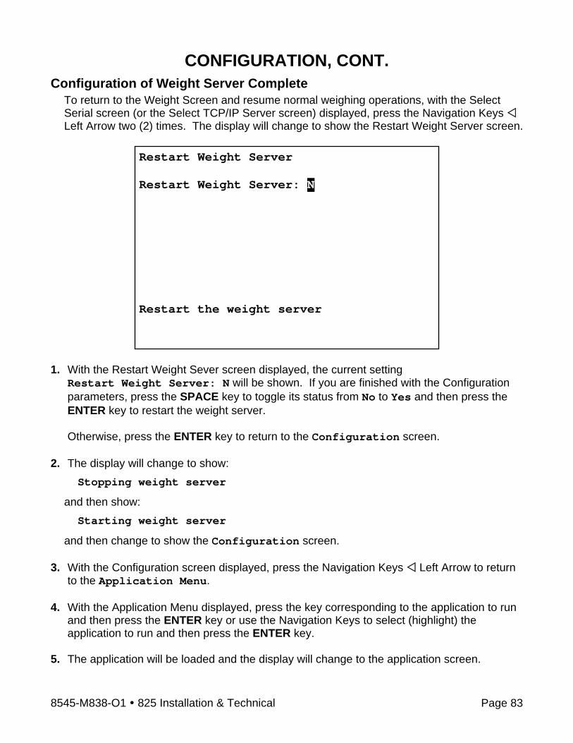
8545-M838-O1 825 Installation & Technical Page 83
CONFIGURATION, CONT. Configuration of Weight Server Complete
To return to the Weight Screen and resume normal weighing operations, with the Select Serial screen (or the Select TCP/IP Server screen) displayed, press the Navigation Keys Left Arrow two (2) times. The display will change to show the Restart Weight Server screen.
1. With the Restart Weight Sever screen displayed, the current setting
Restart Weight Server: N will be shown. If you are finished with the Configuration parameters, press the SPACE key to toggle its status from No to Yes and then press the ENTER key to restart the weight server. Otherwise, press the ENTER key to return to the Configuration screen.
2. The display will change to show:
Stopping weight server
and then show:
Starting weight server
and then change to show the Configuration screen.
3. With the Configuration screen displayed, press the Navigation Keys Left Arrow to return to the Application Menu.
4. With the Application Menu displayed, press the key corresponding to the application to run and then press the ENTER key or use the Navigation Keys to select (highlight) the application to run and then press the ENTER key.
5. The application will be loaded and the display will change to the application screen.
Restart Weight Server Restart Weight Server: N Restart the weight server
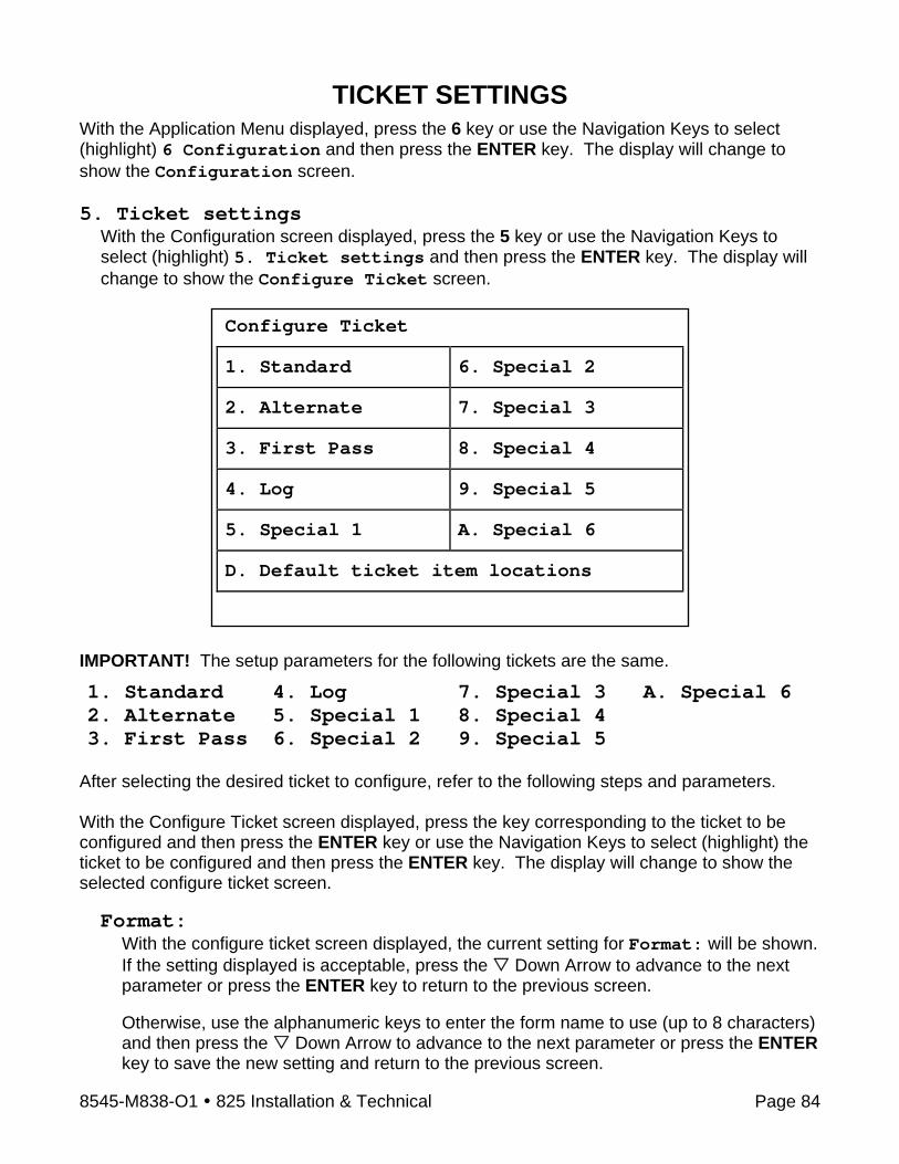
8545-M838-O1 825 Installation & Technical Page 84
TICKET SETTINGS With the Application Menu displayed, press the 6 key or use the Navigation Keys to select (highlight) 6 Configuration and then press the ENTER key. The display will change to show the Configuration screen. 5. Ticket settings
With the Configuration screen displayed, press the 5 key or use the Navigation Keys to select (highlight) 5. Ticket settings and then press the ENTER key. The display will change to show the Configure Ticket screen.
Configure Ticket
1. Standard 6. Special 2
2. Alternate 7. Special 3
3. First Pass 8. Special 4
4. Log 9. Special 5
5. Special 1 A. Special 6
D. Default ticket item locations
IMPORTANT! The setup parameters for the following tickets are the same.
1. Standard 4. Log 7. Special 3 A. Special 6 2. Alternate 5. Special 1 8. Special 4 3. First Pass 6. Special 2 9. Special 5
After selecting the desired ticket to configure, refer to the following steps and parameters. With the Configure Ticket screen displayed, press the key corresponding to the ticket to be configured and then press the ENTER key or use the Navigation Keys to select (highlight) the ticket to be configured and then press the ENTER key. The display will change to show the selected configure ticket screen.
Format:
With the configure ticket screen displayed, the current setting for Format: will be shown. If the setting displayed is acceptable, press the Down Arrow to advance to the next parameter or press the ENTER key to return to the previous screen. Otherwise, use the alphanumeric keys to enter the form name to use (up to 8 characters) and then press the Down Arrow to advance to the next parameter or press the ENTER key to save the new setting and return to the previous screen.
8545-M838-O1 825 Installation & Technical Page 85
TICKET SETTINGS, CONT. Port:
With the configure ticket screen displayed, the current setting for the Port: parameter will be shown. If the setting displayed is acceptable, press the ENTER key to return to the previous screen. Otherwise, press the SPACE key to step through and select the port to use for the standard ticket and then press the ENTER key to save the new setting and return to the previous screen. Available ports are:
COM1-RS232 COM1-Bluetooth COM2 COM3 USB-PRT1 USB-PRT2 USB-PRT3 USB-PRT4 USB-PRT5 USB-PRT6 USB-PC Custom
If Custom is selected, an additional parameter (below the Port:) will be shown. Custom:
With the configure ticket screen displayed and Custom selected for the Port: parameter, the current setting for Custom: will be shown. If the setting displayed is acceptable, press the ENTER key to return to the previous screen. Otherwise, use the alphanumeric keys to enter the port name to use and then press the ENTER key to save the new setting and return to the previous screen.
D. Default ticket item locations
With the Configure Ticket screen displayed, press the D key or use the Navigation Keys to select (highlight) D. Default ticket item location and then press the ENTER key. The display will change to show the Ticket Coordinates screen.
Ticket:
With the Ticket Coordinates screen displayed, the current setting for the Ticket: parameter will be shown. If the setting displayed is acceptable, press the ENTER key to return to the previous screen. Otherwise, press the SPACE key to step through and select the ticket to use and then press the ENTER key to save the new setting and return to the previous screen. Available tickets are:
Default Standard Alternate First Pass Log Special 1 Special 2 Special 3 Special 4 Special 5 Special 6
If Default is selected, the display will change to the Configure tabs page 1 screen. This is the screen to input the Print Tabs Settings.

8545-M838-O1 825 Installation & Technical Page 86
TICKET SETTINGS, CONT. PRINT TABS SETTING (General Format Information)
The general format for the input is: Label: X coordinate, Y coordinate.
Where: Label: = the characters identifying the data printed. X coordinate = the number of spaces to the right. Y coordinate = the number of lines down. NOTE! Enter 0 in either location, X or Y to disable the data from printing.
Configure tabs page 1
With the Ticket Coordinates screen displayed, and Default selected for the Ticket: parameter, the display will change to the Configure tabs page 1 screen.
If the setting displayed for each label is acceptable, press the ENTER key to advance to the Configure tabs page 2 screen or press the press the Left Arrow to return to the previous screen.
Otherwise, use the numeric keys to enter the X coordinate and then press the Down Arrow to advance to the Y coordinate. Again, use the numeric keys to enter the Y coordinate and then press the Down Arrow to advance to the next parameter. NOTE! Use the UP Arrow key to “backup” to the previous coordinate or parameter.
Configure tabs page 1Gross: 0 , 0 Cnv Grs: 0 , 0 Tare: 0 , 0 Cnv Tre: 0 , 0 Net: 0 , 0 Cnv Net: 0 , 0 Dsp Wt: 0 , 0 Cnv Dsp: 0 , 0 G Accum: 0 , 0 Cnv GAcc:0 , 0 N Accum: 0 , 0 Cnv NAcc:0 , 0 Time: 0 , 0 Date: 0 , 0 ID: 0 , 0 CN: 0 , 0 Gross X coordinates
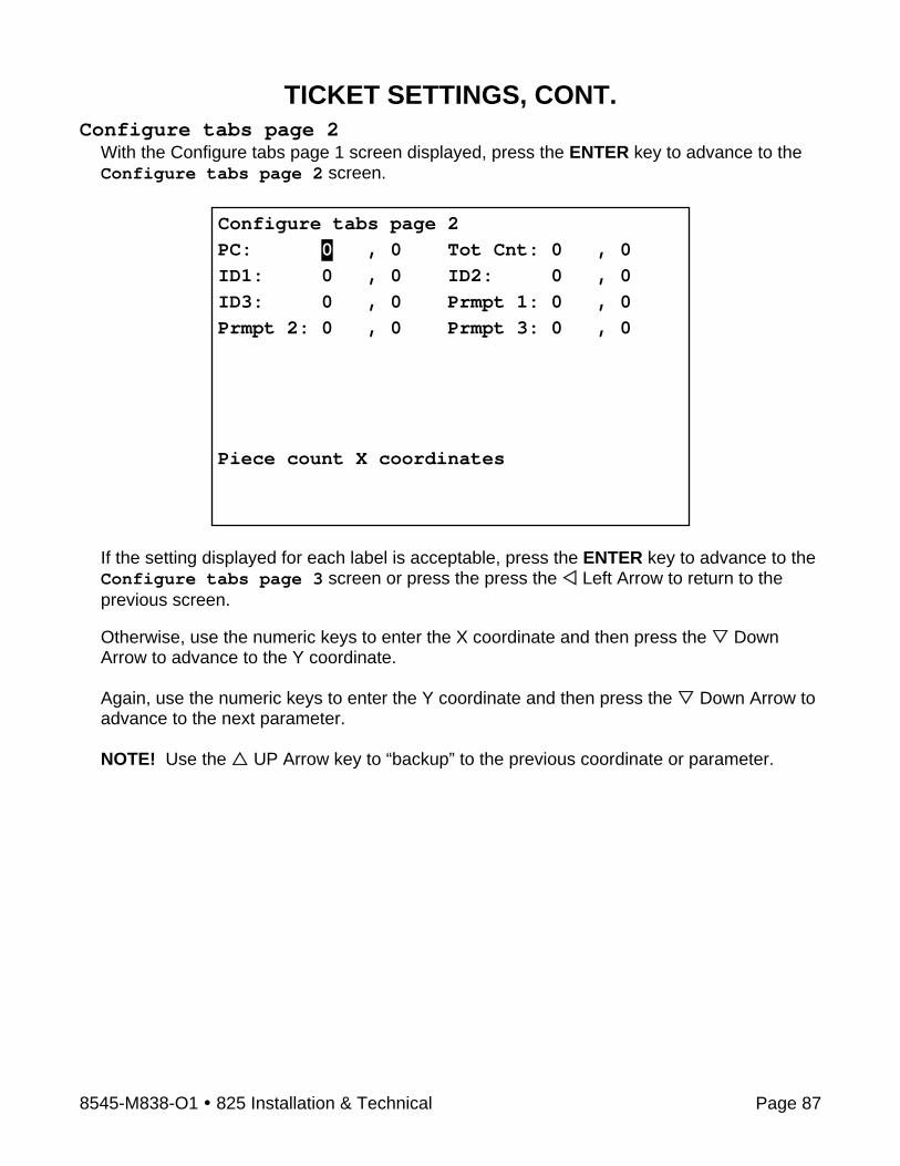
8545-M838-O1 825 Installation & Technical Page 87
TICKET SETTINGS, CONT. Configure tabs page 2
With the Configure tabs page 1 screen displayed, press the ENTER key to advance to the Configure tabs page 2 screen.
If the setting displayed for each label is acceptable, press the ENTER key to advance to the Configure tabs page 3 screen or press the press the Left Arrow to return to the previous screen.
Otherwise, use the numeric keys to enter the X coordinate and then press the Down Arrow to advance to the Y coordinate. Again, use the numeric keys to enter the Y coordinate and then press the Down Arrow to advance to the next parameter. NOTE! Use the UP Arrow key to “backup” to the previous coordinate or parameter.
Configure tabs page 2PC: 0 , 0 Tot Cnt: 0 , 0 ID1: 0 , 0 ID2: 0 , 0 ID3: 0 , 0 Prmpt 1: 0 , 0 Prmpt 2: 0 , 0 Prmpt 3: 0 , 0 Piece count X coordinates

8545-M838-O1 825 Installation & Technical Page 88
TICKET SETTINGS, CONT. Configure tabs page 3
With the Configure tabs page 2 screen displayed, press the ENTER key to advance to the Configure tabs page 3 screen.
If the setting displayed for each line of the Header or Footer is acceptable, press the ENTER key to return to the Configure Ticket screen. Otherwise, use the alphanumeric keys to enter the description (up to 35 characters) for the first line of the header and then press the Down Arrow to advance to the next line. Note that pressing the UP Arrow key will “backup” to the previous line. Continue using the alphanumeric keys to enter the description for each line of the Header and Footer, pressing the Down Arrow key to advance to the next line. When the description for all lines of the Header and Footer have been entered, press the ENTER key to save the new settings and return to the Configure Ticket screen.
Configure tabs page 3 Header 1: _ 2: 3: 4: 5: Footer 1: 2: 3: 4: 5: Header 1
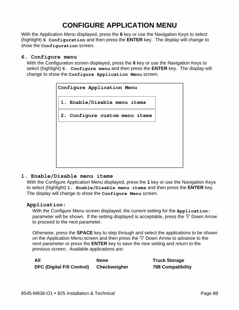
8545-M838-O1 825 Installation & Technical Page 89
CONFIGURE APPLICATION MENU With the Application Menu displayed, press the 6 key or use the Navigation Keys to select (highlight) 6 Configuration and then press the ENTER key. The display will change to show the Configuration screen. 6. Configure menu
With the Configuration screen displayed, press the 6 key or use the Navigation Keys to select (highlight) 6. Configure menu and then press the ENTER key. The display will change to show the Configure Application Menu screen.
1. Enable/Disable menu items
With the Configure Application Menu displayed, press the 1 key or use the Navigation Keys to select (highlight) 1. Enable/Disable menu items and then press the ENTER key. The display will change to show the Configure Menu screen.
Application:
With the Configure Menu screen displayed, the current setting for the Application: parameter will be shown. If the setting displayed is acceptable, press the Down Arrow to proceed to the next parameter.
Otherwise, press the SPACE key to step through and select the applications to be shown on the Application Menu screen and then press the Down Arrow to advance to the next parameter or press the ENTER key to save the new setting and return to the previous screen. Available applications are:
All None Truck Storage DFC (Digital Fill Control) Checkweigher 788 Compatibility
Configure Application Menu
1. Enable/Disable menu items
2. Configure custom menu items
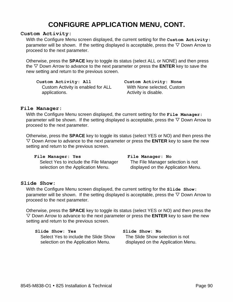
8545-M838-O1 825 Installation & Technical Page 90
CONFIGURE APPLICATION MENU, CONT. Custom Activity:
With the Configure Menu screen displayed, the current setting for the Custom Activity: parameter will be shown. If the setting displayed is acceptable, press the Down Arrow to proceed to the next parameter.
Otherwise, press the SPACE key to toggle its status (select ALL or NONE) and then press the Down Arrow to advance to the next parameter or press the ENTER key to save the new setting and return to the previous screen.
Custom Activity: All Custom Activity: None Custom Activity is enabled for ALL applications.
With None selected, Custom Activity is disable.
File Manager:
With the Configure Menu screen displayed, the current setting for the File Manager: parameter will be shown. If the setting displayed is acceptable, press the Down Arrow to proceed to the next parameter. Otherwise, press the SPACE key to toggle its status (select YES or NO) and then press the
Down Arrow to advance to the next parameter or press the ENTER key to save the new setting and return to the previous screen.
File Manager: Yes File Manager: No Select Yes to include the File Manager selection on the Application Menu.
The File Manager selection is not displayed on the Application Menu.
Slide Show: With the Configure Menu screen displayed, the current setting for the Slide Show: parameter will be shown. If the setting displayed is acceptable, press the Down Arrow to proceed to the next parameter. Otherwise, press the SPACE key to toggle its status (select YES or NO) and then press the
Down Arrow to advance to the next parameter or press the ENTER key to save the new setting and return to the previous screen.
Slide Show: Yes Slide Show: No Select Yes to include the Slide Show selection on the Application Menu.
The Slide Show selection is not displayed on the Application Menu.

8545-M838-O1 825 Installation & Technical Page 91
CONFIGURE APPLICATION MENU, CONT. Auto run:
With the Configure Menu screen displayed, the current setting for the Auto run: parameter will be shown. If the setting displayed is acceptable, press the ENTER key or the Navigation Keys Left Arrow to return to the previous screen. Otherwise, press the SPACE key to step through and select the application to auto run (automatically load and run from the Application Menu screen) and then press the Down Arrow to advance to the next parameter or press the ENTER key to save the new setting and return to the previous screen. Available applications are:
None Truck Storage DFC (Digital Fill Control) Checkweigher 788 Compatibility Custom Application All Configuration File Manager Slide Show
If an application is selected to “auto run”, an additional parameter (below the Auto run:) will be shown.
Auto run secs:
With the Configure Menu screen displayed and an application selected to “auto run”, the current setting for Auto run secs: will be shown. If the setting displayed is acceptable, press the ENTER key to return to the previous screen. Otherwise, use the numeric keys to enter the number of seconds before the application automatically loads and runs (countdown timer on the Application Menu screen) and then press the ENTER key to save the new setting and return to the previous screen. Supported countdown times are 2 through 90 seconds.
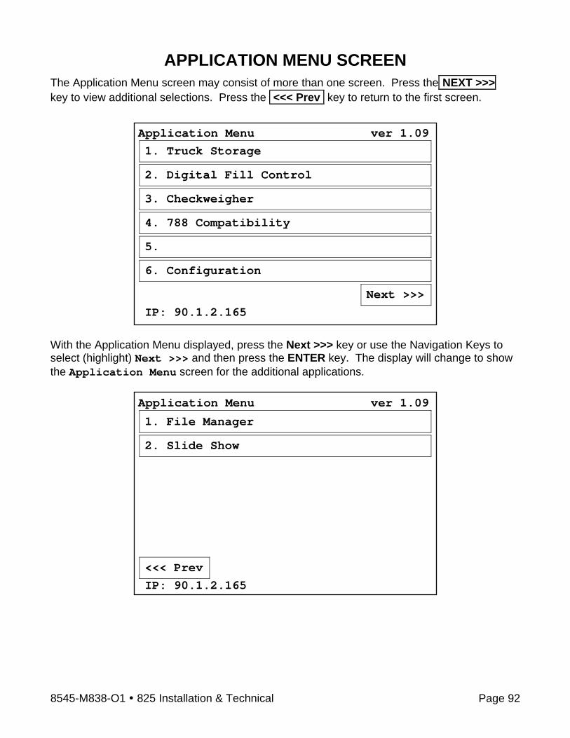
8545-M838-O1 825 Installation & Technical Page 92
APPLICATION MENU SCREEN The Application Menu screen may consist of more than one screen. Press the NEXT >>> key to view additional selections. Press the <<< Prev key to return to the first screen.
With the Application Menu displayed, press the Next >>> key or use the Navigation Keys to select (highlight) Next >>> and then press the ENTER key. The display will change to show the Application Menu screen for the additional applications.
Application Menu ver 1.09
1. File Manager
2. Slide Show
<<< Prev
IP: 90.1.2.165
Application Menu ver 1.09
1. Truck Storage
2. Digital Fill Control
3. Checkweigher
4. 788 Compatibility
5.
6. Configuration
Next >>>
IP: 90.1.2.165

8545-M838-O1 825 Installation & Technical Page 93
TROUBLESHOOTING The 825 is equipped with diagnostic software that tests various portions of the indicator's circuitry and verifies proper operation. Should a problem be detected, an error or status message will be displayed alerting the operator to that condition. The following lists these status messages and errors and their meaning. Weight Status Messages (Displayed concurrently with weight) MOTION
The scale is in motion based on motion range parameter.
BELOW ZERO The gross scale weight reading is below zero.
CENTER ZERO The gross scale weight reading is at center of zero.
Weight Status Messages (Displayed in place of weight) OVER CAPACITY
The scale weight is over capacity (104% of calibrated capacity).
WEIGHT ERROR Weight input signal is out of acceptable range. This may indicate a disconnected or failing load cell.
IMPORTANT! The Totalizer display shows the individual weighing element status in abbreviated form – MO = MOTION, BZ = BELOW ZERO, CZ = CENTER ZERO, OVERCAP = OVER CAPACITY. The Total weight display status is displayed as above.
Operation Messages (Momentarily displayed after operator attempts an action) CANNOT ZERO – MOTION
Attempt to zero scale while in motion.
CANNOT ZERO – OUT OF RANGE Attempt to zero beyond allowed range.
Cannot set tare Tare value invalid.
Cannot change weight units Scale configured for single weight units: custom, lb, or kg.

8545-M838-O1 825 Installation & Technical Page 94
TROUBLESHOOTING, CONT. Operation Messages, Cont. Cannot show net – no tare
The “NET” key operation to show gross, tare, and net weights is not permitted when there is no tare weight.
Cannot print MOTION Attempt to print ticket while scale is in motion.
Cannot print OVER CAPACITY Attempt to print ticket while scale is over capacity.
Cannot print BELOW ZERO Attempt to print ticket while scale is below zero.
Cannot print WEIGHT ERROR Attempt to print ticket during WEIGHT ERROR condition.
Operator not allowed to change scale The current operator login does not permit changing the current scale selection.
Operator not allowed tare The current operator login does not permit using the keypad tare selection.
Operator not allowed push button tare The current operator login does not permit using the push-button tare selection.
Operator not allowed to set date/time The current operator login does not permit setting the date/time.
Operator not allowed to chg units The current operator login does not permit changing the current unit selection.
Operator not allowed to print The current operator login does not permit using the print function.
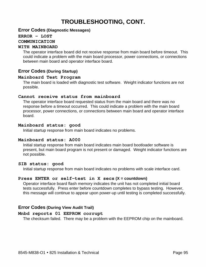
8545-M838-O1 825 Installation & Technical Page 95
TROUBLESHOOTING, CONT. Error Codes (Diagnostic Messages) ERROR – LOST COMMUNICATION WITH MAINBOARD
The operator interface board did not receive response from main board before timeout. This could indicate a problem with the main board processor, power connections, or connections between main board and operator interface board.
Error Codes (During Startup) Mainboard Test Program
The main board is loaded with diagnostic test software. Weight indicator functions are not possible.
Cannot receive status from mainboard The operator interface board requested status from the main board and there was no response before a timeout occurred. This could indicate a problem with the main board processor, power connections, or connections between main board and operator interface board.
Mainboard status: good Initial startup response from main board indicates no problems.
Mainboard status: A000 Initial startup response from main board indicates main board bootloader software is present, but main board program is not present or damaged. Weight indicator functions are not possible.
SIB status: good Initial startup response from main board indicates no problems with scale interface card.
Press ENTER or self-test in X secs (X = countdown) Operator interface board flash memory indicates the unit has not completed initial board tests successfully. Press enter before countdown completes to bypass testing. However, this message will continue to appear upon power-up until testing is completed successfully.
Error Codes (During View Audit Trail) Mnbd reports 01 EEPROM corrupt
The checksum failed. There may be a problem with the EEPROM chip on the mainboard.

8545-M838-O1 825 Installation & Technical Page 96
TROUBLESHOOTING, CONT. Error Codes (During Add Operator) Cannot use same login as existing operator
An attempt was made to enter a new operator using the same login as an existing operator.
No space for new operator An attempt was made to add a new operator when all operator login spaces are filled. The Model 825 supports a total of eight operators. One operator is the Administrator (with full access to all functions and features). The remaining seven are for users and can be configured to allow or prevent access to various functions and features.
Error Codes (During Edit Operator / Delete Operator / Set Default Operator) Operator not found
The operator login entered does not exist.
Cannot delete ADMIN operator An attempt was made to delete the administer login. The administrator login cannot be deleted.
Before You Call Service The Model 825 indicator has been designed to provide you with years of trouble-free operation. In spite of this, troubles sometimes happen. Before calling for service assistance, you should make some initial checks to verify that a problem does exist. The following describes several types of symptoms along with suggested remedies.
PROBLEM POSSIBLE SOLUTIONS Display does not turn on Is the AC power cord fully inserted into the wall
receptacle? Check wall receptacle for proper AC power. Try another electrical appliance in the same receptacle. Does it work? Check the circuit breaker. Has there been power failure?
Incorrect weight displayed Has the indicator been calibrated? Insure that the scale platform is not touching an adjacent object. Check the load cell connector wiring. If using four (4) wire load cells, insure the sense lead jumpers (J1 and J3) on the 825-SIB are installed. Have proper operation procedures been followed?
Indicator will not display weight Refer to Weight Status Messages section and make certain that the OVER CAPACITY message is not displayed. If so, and scale is not loaded, perform the calibration procedure.
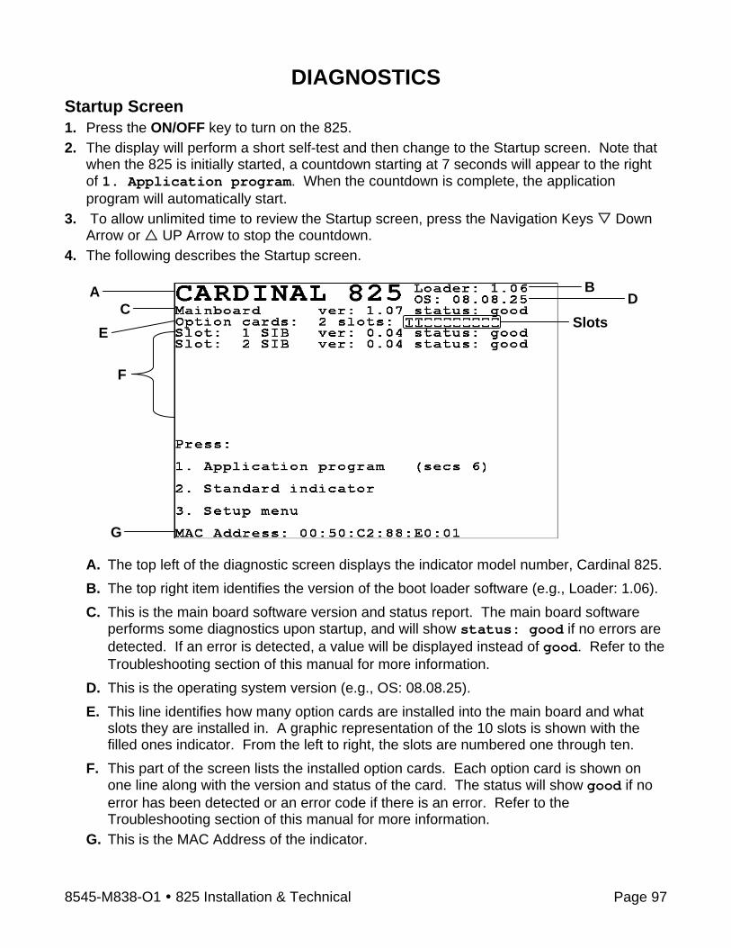
8545-M838-O1 825 Installation & Technical Page 97
DIAGNOSTICS Startup Screen 1. Press the ON/OFF key to turn on the 825. 2. The display will perform a short self-test and then change to the Startup screen. Note that
when the 825 is initially started, a countdown starting at 7 seconds will appear to the right of 1. Application program. When the countdown is complete, the application program will automatically start.
3. To allow unlimited time to review the Startup screen, press the Navigation Keys Down Arrow or UP Arrow to stop the countdown.
4. The following describes the Startup screen.
A. The top left of the diagnostic screen displays the indicator model number, Cardinal 825. B. The top right item identifies the version of the boot loader software (e.g., Loader: 1.06). C. This is the main board software version and status report. The main board software
performs some diagnostics upon startup, and will show status: good if no errors are detected. If an error is detected, a value will be displayed instead of good. Refer to the Troubleshooting section of this manual for more information.
D. This is the operating system version (e.g., OS: 08.08.25). E. This line identifies how many option cards are installed into the main board and what
slots they are installed in. A graphic representation of the 10 slots is shown with the filled ones indicator. From the left to right, the slots are numbered one through ten.
F. This part of the screen lists the installed option cards. Each option card is shown on one line along with the version and status of the card. The status will show good if no error has been detected or an error code if there is an error. Refer to the Troubleshooting section of this manual for more information.
G. This is the MAC Address of the indicator.
A BD
CE
G
F
Slots

8545-M838-O1 825 Installation & Technical Page 98
DIAGNOSTICS, CONT. To Begin Diagnostics With the Startup screen showing, press the Navigation Keys Down Arrow to “advance” to (highlight) the Setup menu option and then press the ENTER key or press the 3 key to select the Setup menu option. The display will change to show the Setup Menu screen.
IMPORTANT! If the Login and Password protection feature has been enable, the Login screen will be displayed instead of the Setup Menu screen. Enter the login and then press the Down Arrow to advance to the password prompt. Enter the password and then press the ENTER key to proceed to the Setup Menu.
Diagnostic Menu
With the Setup Menu displayed, press the 6 key or use the Navigation Keys to select (highlight) 6. Diagnostics and then press the ENTER key. The display will change to show the Diagnostics Menu screen.
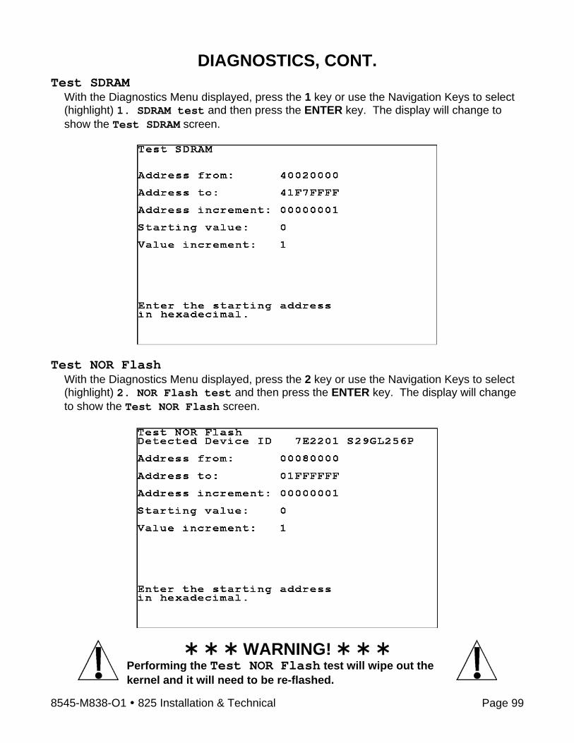
8545-M838-O1 825 Installation & Technical Page 99
DIAGNOSTICS, CONT. Test SDRAM
With the Diagnostics Menu displayed, press the 1 key or use the Navigation Keys to select (highlight) 1. SDRAM test and then press the ENTER key. The display will change to show the Test SDRAM screen.
Test NOR Flash
With the Diagnostics Menu displayed, press the 2 key or use the Navigation Keys to select (highlight) 2. NOR Flash test and then press the ENTER key. The display will change to show the Test NOR Flash screen.
WARNING! Performing the Test NOR Flash test will wipe out the kernel and it will need to be re-flashed.
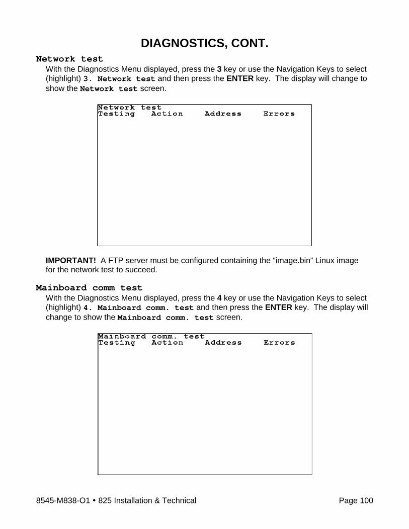
8545-M838-O1 825 Installation & Technical Page 100
DIAGNOSTICS, CONT. Network test
With the Diagnostics Menu displayed, press the 3 key or use the Navigation Keys to select (highlight) 3. Network test and then press the ENTER key. The display will change to show the Network test screen.
IMPORTANT! A FTP server must be configured containing the “image.bin” Linux image for the network test to succeed.
Mainboard comm test
With the Diagnostics Menu displayed, press the 4 key or use the Navigation Keys to select (highlight) 4. Mainboard comm. test and then press the ENTER key. The display will change to show the Mainboard comm. test screen.

8545-M838-O1 825 Installation & Technical Page 101
DIAGNOSTICS, CONT. Test Mainboard I/O
With the Diagnostics Menu displayed, press the 5 key or use the Navigation Keys to select (highlight) 5. Mainboard I/O test and then press the ENTER key. The display will change to show the Test Mainboard I/O screen.
Compact flash test
With the Diagnostics Menu displayed, press the 6 key or use the Navigation Keys to select (highlight) 6. Compact flash test and then press the ENTER key. The display will change to show the Compact flash test screen.

8545-M838-O1 825 Installation & Technical Page 102
DIAGNOSTICS, CONT. Run all tests
With the Diagnostics Menu displayed, press the 7 key or use the Navigation Keys to select (highlight) 7. Run all tests and then press the ENTER key.

8545-M838-O1 825 Installation & Technical Page 103
FINE SPAN ADJUSTMENT If after performing linearization testing, an error in the overall weight (span setting of the scale) or an error in a specific range of weight is found, adjustments can be made using the procedures described below. 1. Press the ON/OFF key to turn on the 825. The display will perform a short self-test and
then change to the Startup screen showing the software versions and diagnostics of the option cards.
2. Press the Navigation Keys Down Arrow to “advance” to (highlight) the Setup menu option and then press the ENTER key or press the 3 key to select the Setup menu option. The display will change to show the Setup Menu screen.
IMPORTANT! If the Login and Password protection feature has been enable, the Login screen will be displayed instead of the Setup Menu screen. Enter the login and then press the Down Arrow to advance to the password prompt. Enter the password and then press the ENTER key to proceed to the Setup Menu.
3. With the Setup Menu displayed, press the 3 key or use the Navigation Keys to select (highlight) 3. Calibration and then press the ENTER key. The display will change to show the Setup Scale Number screen.
4. With the Setup Scale Number screen displayed, verify the correct scale number is shown and then press the ENTER key. Otherwise, use the numeric keys to enter the scale number and then press the ENTER key.
5. The display will change to show the Scale 1 – Calibration Options screen.
6. From the Scale 1 – Calibration Options screen, press the 3 key or use the Navigation Keys to select (highlight) 3. Fine Span and then press the ENTER key.
7. With the Scale 1 – Fine Span screen displayed, place a calibrated test weight on the scale.
Use the Navigation Keys to select (highlight) the Fine Span adjustment option and then press the ENTER key to perform the function or;
Press the U key to increase displayed weight. Press the D key to decrease the displayed weight, Press the Z key to zero the scale. Press the Q key to save the current settings and Quit.
The display will return to the Scale 1 – Calibration Options screen.

8545-M838-O1 825 Installation & Technical Page 104
FINE SPAN ADJUSTMENT, CONT. If 2nd Order Linearization was enabled and the Num Cal Pts parameter is set for 2 or more, then a COEFF option will be added to the Fine Span screen. This option is used to adjust the displayed weight after testing has shown an error in a specific range of weight.
Press the C key or use the Navigation Keys to select (highlight) the Coeff option and then press the ENTER key to proceed to the Coefficient screen. Linear Coefficient:
The Linear Coefficient is applied to the load cell signal to calculate weight. If the current setting displayed for this coefficient is acceptable, press the Down Arrow to advance to the 2nd Order Coeff: parameter. Otherwise, use the numeric keys to enter a new Linear Coefficient and then press the Down Arrow to advance to the next parameter.
2nd Order Coeff: This coefficient is applied to the square of the load cell signal to calculate weight. If the current 2nd Order Coeff setting displayed is acceptable, press the Down Arrow to advance to the Tweak low weight: parameter. Otherwise, use the numeric keys to enter a new 2nd Order Coeff and then press the Down Arrow to advance to the next parameter.
WARNING! Changing the Linear Coefficient or the 2nd Order Coeff will affect the indicator's ability to display the proper weight. Please consult the factory before making any changes.
Tweak low weight: This is the low end of the range of weight that requires adjusting. For example, if after performing linearization testing, the displayed weight is 5 lbs low between 10,000 lbs and 15,000 lbs, the value for the tweak low weight is 10000. If the setting displayed is acceptable, press the Down Arrow to advance to the Tweak high weight: parameter. Otherwise, use the numeric keys to enter the tweak low weight and then press the Down Arrow to advance to the next parameter.
Tweak high weight: This is the high end of the range of weight that requires adjusting. Using the example above, the value for the tweak high weight is 15000. If the setting displayed is acceptable, press the Down Arrow to advance to the Tweak weight: parameter. Otherwise, use the numeric keys to enter the tweak high weight and then press the Down Arrow to advance to the next parameter.

8545-M838-O1 825 Installation & Technical Page 105
FINE SPAN ADJUSTMENT, CONT. Tweak weight:
This is the amount of weight that needs to be added (or subtracted) from the range of weight to bring the displayed weight into tolerance. Again, using the example above, the Tweak Weight would be 5. If the setting displayed is acceptable, press the ENTER key to return to the Scale 1 – Fine Span screen. Otherwise, use the numeric keys to enter a new tweak weight and then press the ENTER key to return to the Scale 1 – Fine Span screen.

8545-M838-O1 825 Installation & Technical Page 106
AUDIT TRAIL COUNTERS A Category 1 Audit Trial is provided on the Model 825 with two event counters that increment when a change is made to features that are required by NTEP or OIML to be sealed. One counter is designated for calibration parameters and one is designated for configuration changes as required in NCWM Publication 14, 2007. Each event counter has a capacity to record 999 changes. The data for the counters is maintained in non-volatile memory and can be viewed by a weights and measures inspector. When selected, the display will show the number of changes and the date and time of the last update to the Calibration and Configuration counters. To View the Audit Trail Counters 1. Press the ON/OFF key to turn on the 825. The display will perform a short self-test and
then change to the Startup screen showing the software versions and diagnostics of the option cards.
2. Press the Navigation Keys Down Arrow to “advance” to (highlight) the Setup menu option and then press the ENTER key or press the 3 key to select the Setup menu option. The display will change to show the Setup Menu screen.
IMPORTANT! If the Login and Password protection feature has been enable, the Login screen will be displayed instead of the Setup Menu screen. Enter the login and then press the Down Arrow to advance to the password prompt. Enter the password and then press the ENTER key to proceed to the Setup Menu.
3. With the Setup Menu displayed, press the 7 key or use the Navigation Keys to select
(highlight) 7. View audit trail and then press the ENTER key. The display will change to show the Audit Trail screen.
4. After viewing the audit trail, press the P key to print the audit trail (using COM1 at the
default baud rate) or press any key to return to the Setup Menu screen.
Audit Trail Last Update Count Date Time Calibration: 11 08/09/2008 14:54:20
Configuration: 20 08/09/2008 13:16:03
Press any key or ‘P’ to print

8545-M838-O1 825 Installation & Technical Page 107
ELECTRONIC TALLEY ROLL (ETR) FILE The 825 is equipped with an Electronic Talley Roll (ETR) file, which stores transaction data each time the indicator receives a Talley command from the computing peripheral. The data is maintained in non-volatile memory for viewing by a weights and measures inspector. Each time the indicator receives an ETR request (SMA XT command), an internal consecutive transaction number (that cannot be modified), the date, time, and the current weight will be stored in memory. The 825 has memory capacity to store up to 7000 transactions in the ETR file. Note that when its capacity is reached, the newest transaction will replace the oldest. IMPORTANT! The ETR file can only be displayed. It cannot be manually cleared or printed. To View the Electronic Talley Roll (ETR) File
1. Press the ON/OFF key to apply power to the 825. The display will perform a short self-test and then change to the Startup screen showing the software versions and diagnostics of the option cards.
2. When the 825 is initially started, a countdown staring at 7 seconds will appear to the right of 1. Application Program. Allow the countdown to complete or press the ENTER key or press the 1 key to select the Application Program option. The display will change to show:
Starting application mode
and then change to show:
Cardinal 825-loading...
Starting...
and then change to show the Application Menu with a countdown starting at 8 seconds appearing to the right of the Indicator selection.
Application Menu ver 1.07
1. Indicator (secs 8)
2. Configuration
3. File Manager
4. Slide Show
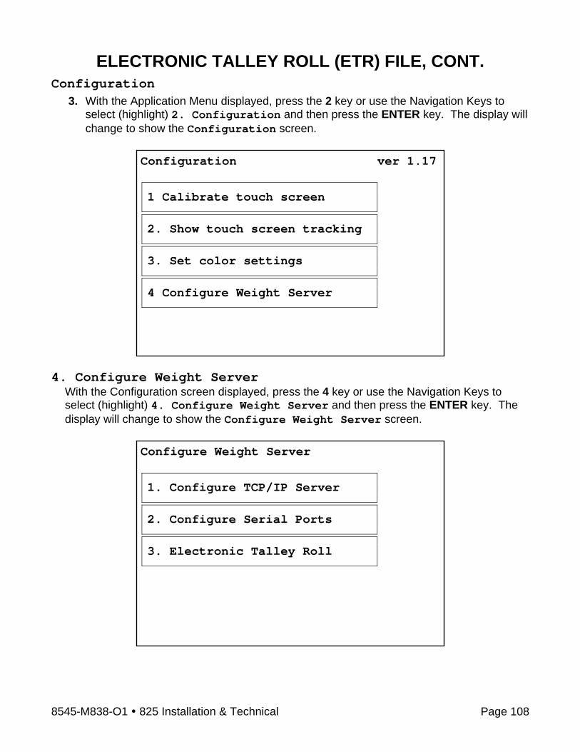
8545-M838-O1 825 Installation & Technical Page 108
ELECTRONIC TALLEY ROLL (ETR) FILE, CONT. Configuration
3. With the Application Menu displayed, press the 2 key or use the Navigation Keys to select (highlight) 2. Configuration and then press the ENTER key. The display will change to show the Configuration screen.
4. Configure Weight Server
With the Configuration screen displayed, press the 4 key or use the Navigation Keys to select (highlight) 4. Configure Weight Server and then press the ENTER key. The display will change to show the Configure Weight Server screen.
Configuration ver 1.17
1 Calibrate touch screen
2. Show touch screen tracking
3. Set color settings
4 Configure Weight Server
Configure Weight Server
1. Configure TCP/IP Server
2. Configure Serial Ports
3. Electronic Talley Roll

8545-M838-O1 825 Installation & Technical Page 109
ELECTRONIC TALLEY ROLL (ETR) FILE, CONT. 3. Electronic Talley Roll
With the Configure Weight Server screen displayed, press the 3 key or use the Navigation Keys to select (highlight) 3. Electronic Talley Roll and then press the ENTER key. The display will change to show the Select ETR Range screen.
Select ETR Range From:
With the Select ETR Range screen displayed, the setting for From: (the ETR range starting number) will be shown. If the number displayed is acceptable, press the Down Arrow to proceed to the To: parameter.
Otherwise, use the numeric keys to enter the ETR starting number and then press the Down Arrow to “advance” to the To: parameter.
To: With the Select ETR Range screen displayed, the setting for To: (the ETR range ending number) will be shown. If the number displayed is acceptable, press the ENTER key to proceed to the ETR Report screen. Otherwise, use the numeric keys to enter the ETR ending number and then press the ENTER key to proceed to the ETR Report screen.
ETR Report
After viewing the ETR Report for the number or range of numbers entered, press any key to return to the Select ETR Range screen.
ETR Report Num Date Time Weight Press any key

8545-M838-O1 825 Installation & Technical Page 110
ELECTRONIC TALLEY ROLL (ETR) FILE, CONT. Return to Normal Operations
To return to the Weight Screen and resume normal weighing operations, with the Select ETR Range screen displayed, press the Navigation Keys Left Arrow three (3) times to return to the Application Menu.
With the Application Menu displayed, press the 1 key or use the Navigation Keys to select (highlight) 1. Indicator and then press the ENTER key. The display will change to show the Weight screen. Normal weighing operations can now resume.
Application Menu ver 1.07
1. Indicator (secs 8)
2. Configuration
3. File Manager
4. Slide Show

8545-M838-O1 825 Installation & Technical Page 111
NOTES

8545-M838-O1 825 Installation & Technical Page 112
NOTES

8545-M838-O1 825 Installation & Technical Page 113
PART IDENTIFICATION ITEM # QTY. PART NUMBER DESCRIPTION
1 26 6013-0039 NUT #6-32 HEX 2 1 6013-0297 NUT #10-32 HEX 3 18 6013-0433 NUT #10-32 HEX ACORN LOCK SS 4 1 6024-0037 WASHER LOCK HELICAL SP #10 REG SS 5 10 6024-1022 WASHER FLAT #6 Z/P 6 14 6024-1078 WASHER FLAT #6 NEOPRENE BACKING SS 7 1 6610-1506 CONN GLAND .160-.310 GRIP .60 MTG NICKEL 8 5 6610-2248 CONN GLAND .187-.312 GRIP .599 MTG BLK 9 1 6610-5002 GROUND LUG L-35 10 12 6680-0004 WASHER LOCK INT TOOTH #6 TYPE A Z-PL 11 4 6680-0220 SPACER #6 x .875 12 1 6980-1030 POWER CORD 18/3 SVT CEE 6.3 FT. 13 1 8545-B810-08 ACCESS PLATE 14 1 8545-B814-08 ACCESS PLATE GASKET 15 1 8545-C815-08 REAR PANEL 16 1 8545-C816-08 REAR PANEL GASKET 17 1 8545-C822-0A BEZEL WELDMENT 18 1 8545-C834-0A POWER SUPPLY ASSEMBLY 19 1 8545-D835-0A SUB-CHASSIS ASSEMBLY 20 1 8545-D810-08 KEYPAD: 825 INDICATOR 21 1 8545-D833-0A FRONT ENCLOSURE WELDMENT 22 4 6540-1104 HOLE PLUG, 0.173-0.240 23 6710-0030 TAPE, DBL. SIDED 0.5” WIDE 24 1 593GR986 SERIAL TAG ASSY. 25 1 6650-0087 LABEL, MADE IN THE USA 26 1 6610-5084 TERMINAL BLOCK, 3 POS.
Amount required to extend past edge of enclosure. See illustration on the next page.
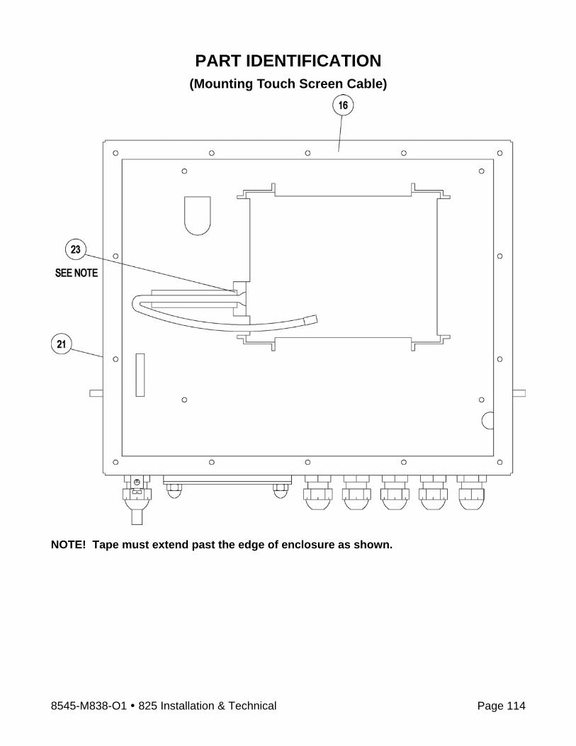
8545-M838-O1 825 Installation & Technical Page 114
PART IDENTIFICATION (Mounting Touch Screen Cable)
NOTE! Tape must extend past the edge of enclosure as shown.
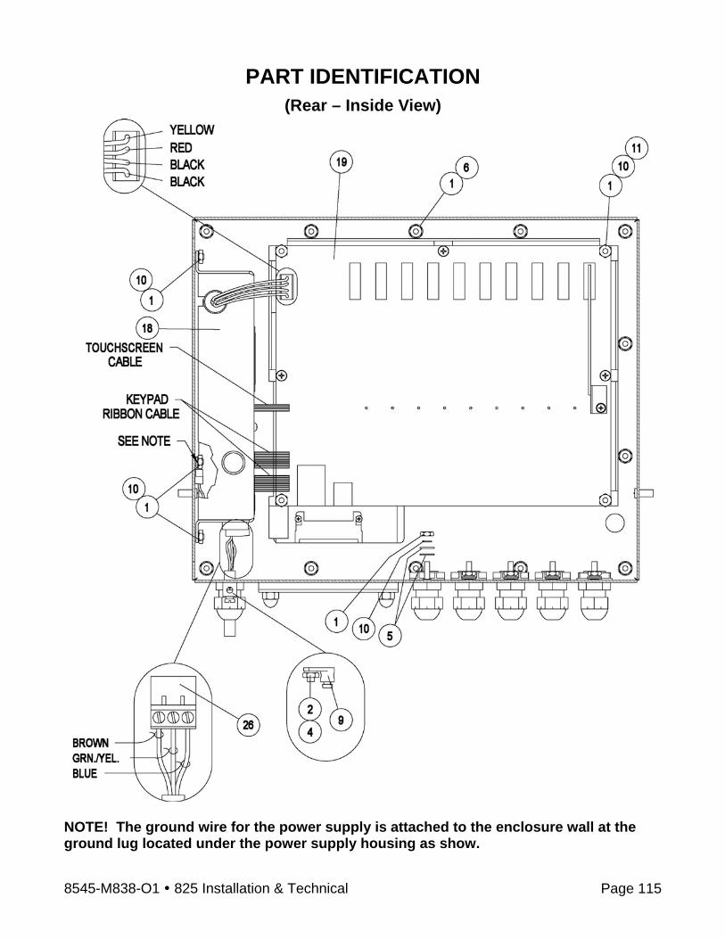
8545-M838-O1 825 Installation & Technical Page 115
PART IDENTIFICATION (Rear – Inside View)
NOTE! The ground wire for the power supply is attached to the enclosure wall at the ground lug located under the power supply housing as show.
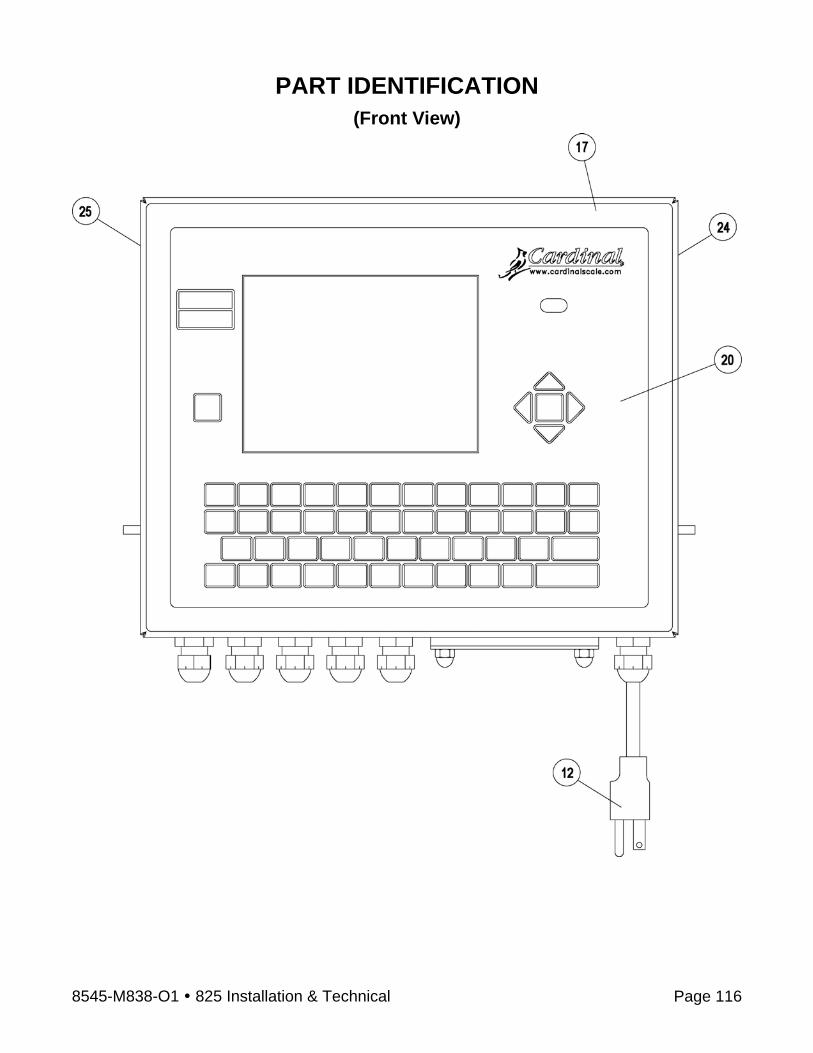
8545-M838-O1 825 Installation & Technical Page 116
PART IDENTIFICATION (Front View)

8545-M838-O1 825 Installation & Technical Page 117
PART IDENTIFICATION (Rear View)

STATEMENT OF LIMITED WARRANTY
WARRANTY TERMSCardinal Scale Manufacturing Company warrants the equipment we manufacture against defects in material and workmanship. The length and terms and conditions of these warranties vary with the type of product and are summarized below:
PRODUCTTYPE
TERMMATERIAL ANDWORKMANSHIP
LIGHTNINGDAMAGE
See note 9
WATER DAMAGE
See note 7
CORROSIONSee note 4
ON-SITELABOR
LIMITATIONSAND
REQUIREMENTS
VEHICLE SCALE WEIGHT
INDICATORS
1YEARS
YES YES YES YES NO1, 2, 3, 5, 6A, B, C, D
VEHICLE SCALE LOAD CELLSEx. Hydraulic
5 YEARS
YES YES YES YES 90 DAYS1, 2, 3, 5, 6A, B, C, D
HYDRAULICLOAD CELLS
LIFE YES YES YES YES 90 DAYS1, 5, 6, 8A, B, C, D
VEHICLESCALE
STRUCTURE
5YEARS
YES YES YES YES 90 DAYS1, 2, 3, 5, 6A, B, C, D
ALL OTHERCARDINALPRODUCTS
1YEAR
YES NO YES YES NO1, 2, 5, 6A, B, C, D
REPLACEMENTPARTS
90DAYS
YES NO YES YES NO1, 2, 4, 5, 6A, B, C, D
IN-MOTIONVEHICLESCALES
1YEAR
YES NO YES YES 90 DAYS1, 2, 5, 6A, B, C, D
APPLICABLE LIMITATIONS AND REQUIREMENTSThis warranty applies only to the original purchaser. The warranty does not apply to equipment that has been tampered with, defaced, damaged, or had repairs or modifications not authorized by Cardinal or has had the serial number altered, defaced or removed.This warranty is not applicable to equipment that has not been grounded in accordance with Cardinal’s recommendations.This equipment must be installed and continuously maintained by an authorized Cardinal dealer.Applies only to components constructed from stainless steel.This warranty does not apply to equipment damaged in transit. Claims for such damage must be made with the responsible freight carrier in accordance with freight carrier regulations.Warranty term begins with date of shipment from Cardinal.Only if device is rated NEMA 4 or better or IP equivalent.Lifetime warranty applies to damages resulting from water, lightning, and voltage transients and applies only to the hydraulic load cell structure itself (does not include pressure transducers, rubber seals, o-rings, and associated wiring).Except for hydraulic load cells, warranty coverage for damage resulting from lightning is valid ONLY when the device is installed in strict accordance with Cardinal’s installation instructions including the use of recommended grounding and surge suppression circuitry.
1.
2.3.4.5.
6.7.8.
9.
12/07Printed in USA
315-WARRANTY-CAR-E
Ph. (800) 441-4237E-mail: [email protected]
203 E. DaughertyWebb City, MO 64870
- Page 1 -

12/07Printed in USA
315-WARRANTY-CAR-E
Ph. (800) 441-4237E-mail: [email protected]
203 E. DaughertyWebb City, MO 64870
EXCLUSIONS
This warranty does not include replacement of consumable of expendable parts. The warranty does not apply to any item that has been damaged due to unusual wear, abuse, improper line voltage, overloading, theft, fire, lightning, water, pro-longed storage or exposure while in purchaser’s possession or acts of God unless otherwise stated herein.
This warranty does not apply to peripheral equipment not manufactured by Cardinal. This equipment will normally be covered by the equipment manufacturer’s warranty.
This warranty sets forth the extent of our liability for breach of any warranty or deficiency in connection with the sale or use of our product. Cardinal will not be liable for consequential damages of any nature, including but not limited to loss of profit, delays or expenses, whether based on tort or contract. Cardinal reserves the right to incorporate improvements in material and design without notice and is not obligated to incorporate said improvements in equipment previously manufactured.
This warranty is in lieu of all other warranties expressed or implied including any warranty that extends beyond the de-scription of the product including any warranty of merchantability or fitness for a particular purpose. This warranty covers only those Cardinal products installed in the forty-eight contiguous United States and Canada.
- Page 2 -
A.)
B.)
C.)
D.)

8545-M838-O1 825 Installation & Technical Page 120