Embed Size (px)
Citation preview
FLYBP03 for DYFA3030 Printed in USA
READ THROUGH THIS INSTRUCTION MANUAL FIRST. IT CONTAINSIMPORTANT INSTRUCTIONS AND WARNINGS CONCERNING THE ASSEMBLYAND USE OF THIS MODEL.
Entire Contents © Copyright 1997
Instruction Manual
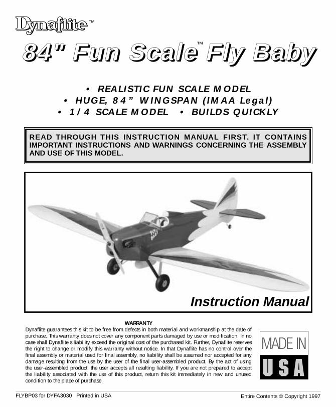
• REALISTIC FUN SCALE MODEL• HUGE, 84” WINGSPAN (IMAA Legal)
• 1/4 SCALE MODEL • BUILDS QUICKLY
WARRANTYDynaflite guarantees this kit to be free from defects in both material and workmanship at the date ofpurchase. This warranty does not cover any component parts damaged by use or modification. In nocase shall Dynaflite's liability exceed the original cost of the purchased kit. Further, Dynaflite reservesthe right to change or modify this warranty without notice. In that Dynaflite has no control over thefinal assembly or material used for final assembly, no liability shall be assumed nor accepted for anydamage resulting from the use by the user of the final user-assembled product. By the act of usingthe user-assembled product, the user accepts all resulting liability. If you are not prepared to acceptthe liability associated with the use of this product, return this kit immediately in new and unusedcondition to the place of purchase.
™
™
88884444"""" FFFFuuuunnnn SSSSccccaaaalllleeee FFFFllllyyyy BBBBaaaabbbbyyyy
Introduction ........................................................2Precautions.........................................................3Preparations.......................................................4Required Items ..................................................4Optional Items ..................................................4Suggested Supplies ...........................................4Building Notes ..................................................5Types of Wood..................................................5Metric Conversions ............................................5
Die Patterns ...................................................6&7Build the Tail Group ............................................8Build the Fin......................................................8Build the Rudder................................................8Build the Stabilizer ............................................9Build the Elevators .............................................9
Build the Wing....................................................9Join the Wing Halves.......................................14Build the Ailerons ............................................16
Build the Fuselage.............................................16Final Assembly .................................................20Finishing ..........................................................24Set the Control Throws ......................................25Balance the Model ............................................26Preflight ...........................................................26At Home..........................................................26At The Flying Site .............................................26Engine Safety Precautions .................................27Flight................................................................27Find a Safe Place to Fly.....................................27Takeoff ................................................Back CoverFlying .................................................Back CoverLanding...............................................Back Cover
Congratulations on your choice of this kit for yournext project. The Fly Baby is a Fun Scale™ model ofa true classic aircraft. It has the presence that only abig model can carry off. The full scale Fly Baby wasactually derived from a model aircraft. This kit is amodel of that full scale aircraft.
The Dynaflite Fly Baby was designed to allow themodeler a wide selection of power plants from a .75two stroke to a 25 cc gas engine. With an airplanethis large and a power plant selection this broad,there are a few problems that may come up. If youuse a light .75 two stroke you will need to addweight to the nose. A .91 4 stroke will balance veryclosely. With a gas motor like the US Engines 25ccyou will need to add weight in the tail.
At Dynaflite we take pride in offering kits that aresimple and straightforward to build and providevalue for your modeling dollar. Because of the sizeand cost of this model, we assume you have builtseveral models and have a general workingknowledge of modeling and its terms.
If you HAVE NOT built and flown several kits, doyourself a favor - back up and get some experiencebefore beginning this kit.
Please inventory and inspect all parts carefullybefore starting to build! If any parts are missing,broken or defective or if you have any questionsabout building or flying this model, please call us at(217) 398-8970 and we'll be glad to help. If you arecalling for replacement parts, please look up thepart numbers and have them ready when calling.
INTRODUCTIONTABLE OF CONTENTS
2
3
Your Fly Baby is not a toy, but a sophisticated workingmodel that functions like a full-size airplane. Becauseof its performance, if you do not assemble andoperate the Fly Baby correctly, you could possiblyinjure yourself or spectators and damage property. Tomake your R/C modeling experience totallyenjoyable, we recommend that you get assistancewith assembly and your first flights from anexperienced, knowledgeable modeler. You'll learnfaster and avoid risk to your model before you'retruly ready to solo. Your local hobby shop hasinformation about flying clubs in your area whosemembership includes qualified instructors.
You can also contact the national Academy of ModelAeronautics (AMA), which has more than 2,500chartered clubs across the country. We recommendyou join the AMA which will provide you withinsurance coverage at AMA club sites and events.AMA Membership is required at chartered clubfields where qualified flight instructors are available.Contact the AMA at the address or toll-free phonenumber below.
Academy of Model Aeronautics5151 East Memorial Drive
Muncie, IN 47302(800) 435-9262
Fax (765) 741-0057
1. You must assemble the plane according to theinstructions. Do not alter or modify the model, asdoing so may result in an unsafe or unflyable model.In a few cases the instructions may differ slightlyfrom the photos or plan. In those instances the textshould be taken as correct.
2. You must take time to build straight, true and strong.
3. You must install all R/C and other components sothat the model operates properly on the ground andin the air.
4. You must test the operation of the model before thefirst and each successive flight to insure that allequipment operates correctly. You must also makecertain that the model has remained structurally sound.
NOTE: We, as the kit manufacturer, provide youwith a quality kit and great instructions, butultimately the quality and flyability of your finishedmodel depends on how you assemble it; therefore,we cannot in any way guarantee the performanceof your completed model and no representationsare expressed or implied as to the performance orsafety of your completed model.
PRECAUTIONSPROTECT YOUR MODEL,YOURSELF & OTHERS...
FOLLOW THIS IMPORTANTSAFETY PRECAUTION
These are the items “not included“ with your kit; youwill need to purchase them separately. Items inparentheses (GPMQ4107) are suggested partnumbers recognized by distributors and hobbyshops and are listed for your ordering convenience.GPM is the Great Planes® brand, TOP is the TopFlite® brand and HCA is the Hobbico® brand.
❏ 4 channel radio with 6 servos (5 high torque to be IMAA legal)
❏ Engine - .75 to .90 2-stroke .91 to 1.20 4-stroke or 25cc gas
❏ Engine mount and mounting hardware❏ 16 oz. Fuel tank, 2 or 4-stroke (GPMQ4107)❏ 20 oz. Fuel tank, gas (DUBQ0220)❏ Gas stopper (DUBQ0675)❏ Standard fuel tubing, 2 or 4-stroke (GPMQ4131)❏ Tygon fuel tubing, gas (AERQ2125)❏ (2) 4-1/2" Main wheels (DUBQ0846)❏ (1) 1-1/2" Tail wheel (GPMQ4243)❏ (4) 1/4" Wheel collars (DUBQ1200)❏ (2) 3/32" Wheel collars (GPMQ4302)❏ Coverite™ Fabric covering – Main color one
15’ roll – Trim colors one 6’ roll per color❏ Paint for fuelproofing and engine cowl ❏ (1) 1/4 Scale pilot (DGAQ2110)❏ 1/4" Latex Foam Rubber (HCAQ1000)❏ (2) 12" Servo extension wires (ailerons) ❏ (2) ‘Y’ Connectors (ailerons, elevators) ❏ (2) 24" Servo extension wires (gas only)
❏ Cockpit and Accessory Kit (DYFQ8110)
We recommend Great Planes Pro™ CA and Epoxy❏ 4 oz. Thin CA Adhesive - (GPMR6004)❏ 4 oz. Medium CA Adhesive (GPMR6010)❏ 2 oz. Thick CA Adhesive - (GPMR6015)❏ CA Accelerator - (GPMR6035)❏ CA Applicator Tips - (HCAR3780)❏ 6-Minute Epoxy - (GPMR6045)❏ 30-Minute Epoxy - (GPMR6047)❏ 4 oz. Aliphatic Resin Glue (GPMR6161)❏ 4 oz. Milled Fiberglass (GPMR6165)❏ Microballoon Filler (TOPR1090)❏ J & Z Products RC/56 Canopy Glue
(JOZR5007)❏ Great Planes Plan Protector (GPMR6167)
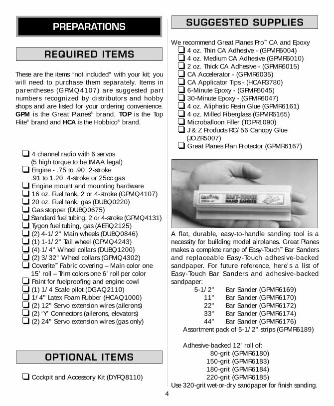
A flat, durable, easy-to-handle sanding tool is anecessity for building model airplanes. Great Planesmakes a complete range of Easy-Touch™ Bar Sandersand replaceable Easy-Touch adhesive-backedsandpaper. For future reference, here's a list of Easy-Touch Bar Sanders and adhesive-backedsandpaper:
5-1/2" Bar Sander (GPMR6169)11" Bar Sander (GPMR6170)22" Bar Sander (GPMR6172)33" Bar Sander (GPMR6174)44" Bar Sander (GPMR6176)
Assortment pack of 5-1/2" strips (GPMR6189)
Adhesive-backed 12' roll of:80-grit (GPMR6180)
150-grit (GPMR6183)180-grit (GPMR6184)220-grit (GPMR6185)
Use 320-grit wet-or-dry sandpaper for finish sanding.
SUGGESTED SUPPLIES
OPTIONAL ITEMS
REQUIRED ITEMS
PREPARATIONS
4
5
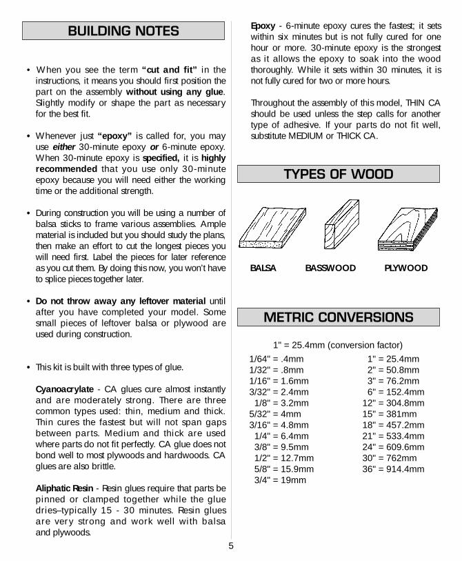
• When you see the term “cut and fit” in theinstructions, it means you should first position thepart on the assembly without using any glue.Slightly modify or shape the part as necessaryfor the best fit.
• Whenever just “epoxy” is called for, you mayuse either 30-minute epoxy or 6-minute epoxy.When 30-minute epoxy is specified, it is highlyrecommended that you use only 30-minuteepoxy because you will need either the workingtime or the additional strength.
• During construction you will be using a number ofbalsa sticks to frame various assemblies. Amplematerial is included but you should study the plans,then make an effort to cut the longest pieces youwill need first. Label the pieces for later referenceas you cut them. By doing this now, you won’t haveto splice pieces together later.
• Do not throw away any leftover material untilafter you have completed your model. Somesmall pieces of leftover balsa or plywood areused during construction.
• This kit is built with three types of glue.
Cyanoacrylate - CA glues cure almost instantlyand are moderately strong. There are threecommon types used: thin, medium and thick.Thin cures the fastest but will not span gapsbetween parts. Medium and thick are usedwhere parts do not fit perfectly. CA glue does notbond well to most plywoods and hardwoods. CAglues are also brittle.
Aliphatic Resin - Resin glues require that parts bepinned or clamped together while the glue dries–typically 15 - 30 minutes. Resin glues are very strong and work well with balsa and plywoods.
Epoxy - 6-minute epoxy cures the fastest; it setswithin six minutes but is not fully cured for onehour or more. 30-minute epoxy is the strongest as it allows the epoxy to soak into the woodthoroughly. While it sets within 30 minutes, it isnot fully cured for two or more hours.
Throughout the assembly of this model, THIN CAshould be used unless the step calls for anothertype of adhesive. If your parts do not fit well,substitute MEDIUM or THICK CA.
BALSA BASSWOOD PLYWOOD
1" = 25.4mm (conversion factor)
METRIC CONVERSIONS
TYPES OF WOOD
BUILDING NOTES
1/64" = .4mm1/32" = .8mm1/16" = 1.6mm3/32" = 2.4mm1/8" = 3.2mm
5/32" = 4mm3/16" = 4.8mm1/4" = 6.4mm3/8" = 9.5mm1/2" = 12.7mm5/8" = 15.9mm3/4" = 19mm
1" = 25.4mm2" = 50.8mm3" = 76.2mm6" = 152.4mm
12" = 304.8mm15" = 381mm18" = 457.2mm21" = 533.4mm24" = 609.6mm30" = 762mm36" = 914.4mm
6
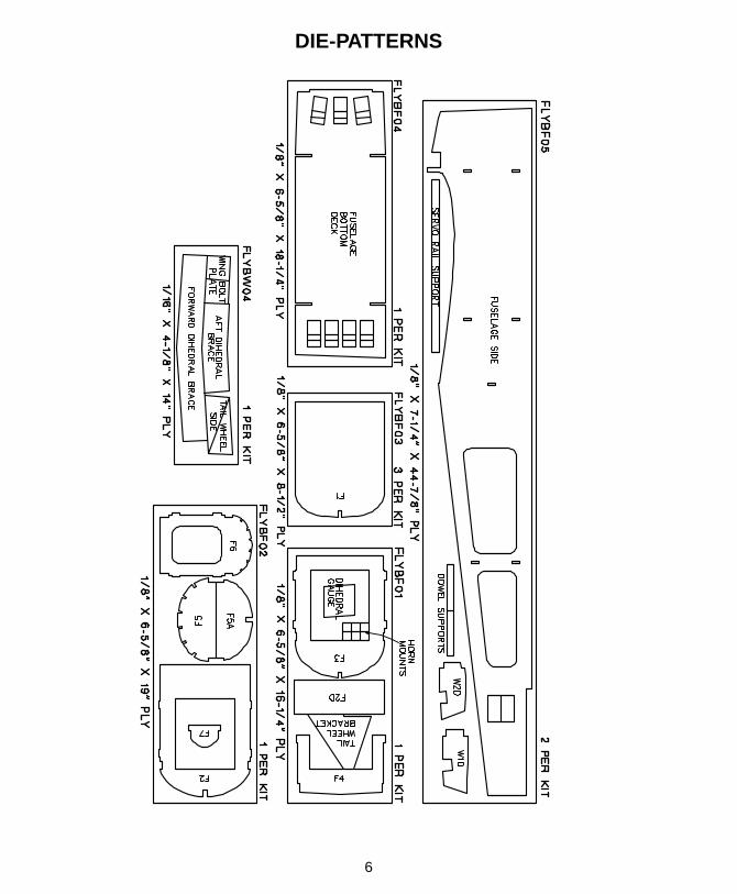
DIE-PATTERNS
7
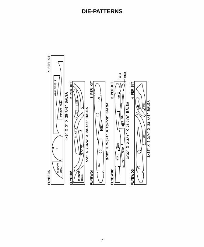
DIE-PATTERNS
❏ 1. Place the fin and rudder plan on your worksurface and cover it with wax paper.
❏ 2. From the 3/8"x 15/16"x 36" balsa stick cut,fit and glue the fin TE and fin upper bottom piece(shaded area on plan).
❏ 3. From a 3/8"x 5/8"x 30" balsa stick cut, fitand glue the fin lower bottom piece (shaded area on plans).
❏ 4. From a 3/8"x 5/8"x 30" balsa stick cut, fitand glue the fin LE.
❏ 5. From a 1/8" x 3/8" x 24" balsa stick cut, fitand glue the fin ribs in place.
NOTE: It is important that the ribs fit the LE and TEwell. It is not important that each rib fit the exactlocation shown on the plan.
❏ 6. Use leftover 3/8" x 15/16" balsa to cut andglue the gusset between the Fin LE and Fin Bottom.
❏ 7. Sand both sides of the fin flat. Radius the LE asshown on the plan.
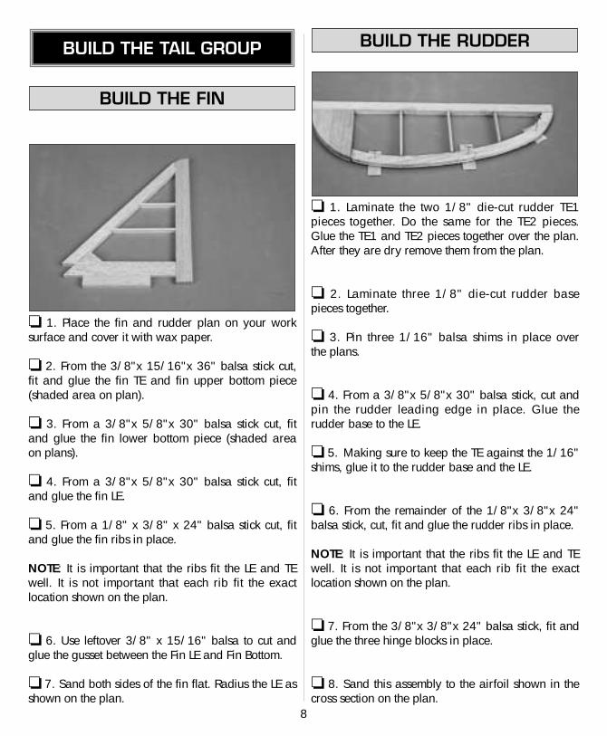
❏ 1. Laminate the two 1/8" die-cut rudder TE1pieces together. Do the same for the TE2 pieces.Glue the TE1 and TE2 pieces together over the plan.After they are dry remove them from the plan.
❏ 2. Laminate three 1/8" die-cut rudder base pieces together.
❏ 3. Pin three 1/16" balsa shims in place over the plans.
❏ 4. From a 3/8"x 5/8"x 30" balsa stick, cut andpin the rudder leading edge in place. Glue therudder base to the LE.
❏ 5. Making sure to keep the TE against the 1/16"shims, glue it to the rudder base and the LE.
❏ 6. From the remainder of the 1/8"x 3/8"x 24"balsa stick, cut, fit and glue the rudder ribs in place.
NOTE: It is important that the ribs fit the LE and TEwell. It is not important that each rib fit the exactlocation shown on the plan.
❏ 7. From the 3/8"x 3/8"x 24" balsa stick, fit andglue the three hinge blocks in place.
❏ 8. Sand this assembly to the airfoil shown in thecross section on the plan.
BUILD THE RUDDER
BUILD THE FIN
BUILD THE TAIL GROUP
8
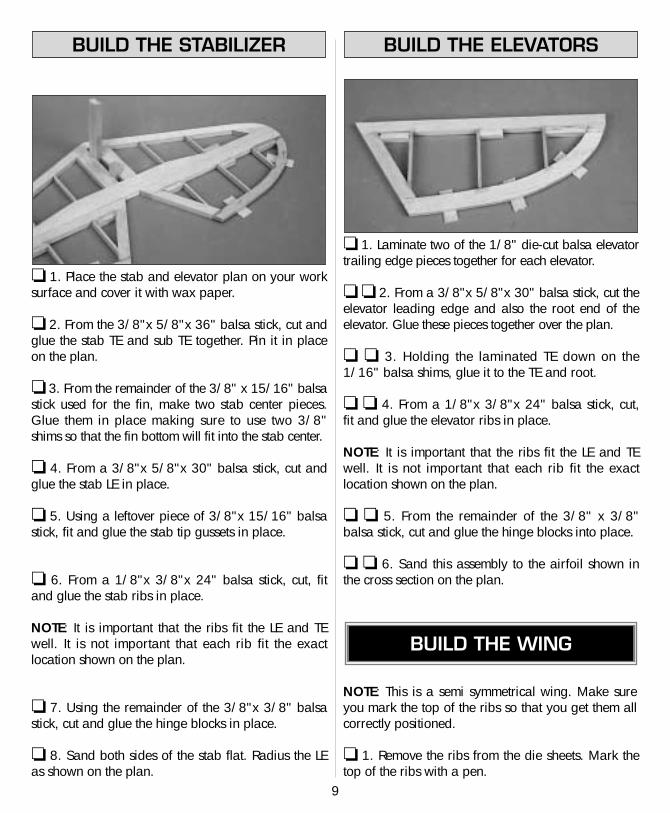
❏ 1. Place the stab and elevator plan on your worksurface and cover it with wax paper.
❏ 2. From the 3/8"x 5/8"x 36" balsa stick, cut andglue the stab TE and sub TE together. Pin it in placeon the plan.
❏ 3. From the remainder of the 3/8" x 15/16" balsastick used for the fin, make two stab center pieces.Glue them in place making sure to use two 3/8"shims so that the fin bottom will fit into the stab center.
❏ 4. From a 3/8"x 5/8"x 30" balsa stick, cut andglue the stab LE in place.
❏ 5. Using a leftover piece of 3/8"x 15/16" balsastick, fit and glue the stab tip gussets in place.
❏ 6. From a 1/8"x 3/8"x 24" balsa stick, cut, fitand glue the stab ribs in place.
NOTE: It is important that the ribs fit the LE and TEwell. It is not important that each rib fit the exactlocation shown on the plan.
❏ 7. Using the remainder of the 3/8"x 3/8" balsastick, cut and glue the hinge blocks in place.
❏ 8. Sand both sides of the stab flat. Radius the LEas shown on the plan.
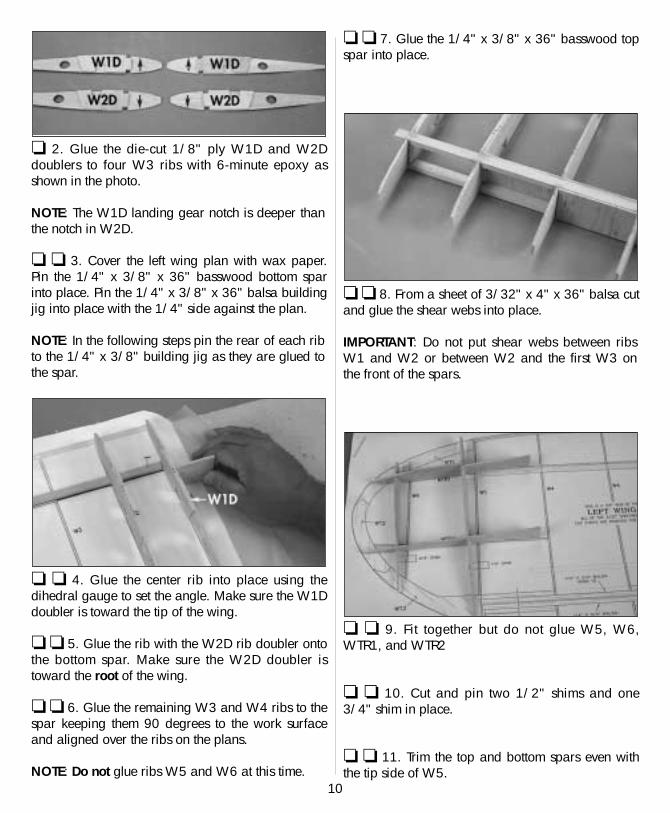
❏ 1. Laminate two of the 1/8" die-cut balsa elevatortrailing edge pieces together for each elevator.
❏ ❏ 2. From a 3/8"x 5/8"x 30" balsa stick, cut theelevator leading edge and also the root end of theelevator. Glue these pieces together over the plan.
❏ ❏ 3. Holding the laminated TE down on the1/16" balsa shims, glue it to the TE and root.
❏ ❏ 4. From a 1/8"x 3/8"x 24" balsa stick, cut,fit and glue the elevator ribs in place.
NOTE: It is important that the ribs fit the LE and TEwell. It is not important that each rib fit the exactlocation shown on the plan.
❏ ❏ 5. From the remainder of the 3/8" x 3/8"balsa stick, cut and glue the hinge blocks into place.
❏ ❏ 6. Sand this assembly to the airfoil shown inthe cross section on the plan.
NOTE: This is a semi symmetrical wing. Make sureyou mark the top of the ribs so that you get them allcorrectly positioned.
❏ 1. Remove the ribs from the die sheets. Mark thetop of the ribs with a pen.
BUILD THE WING
BUILD THE ELEVATORSBUILD THE STABILIZER
9
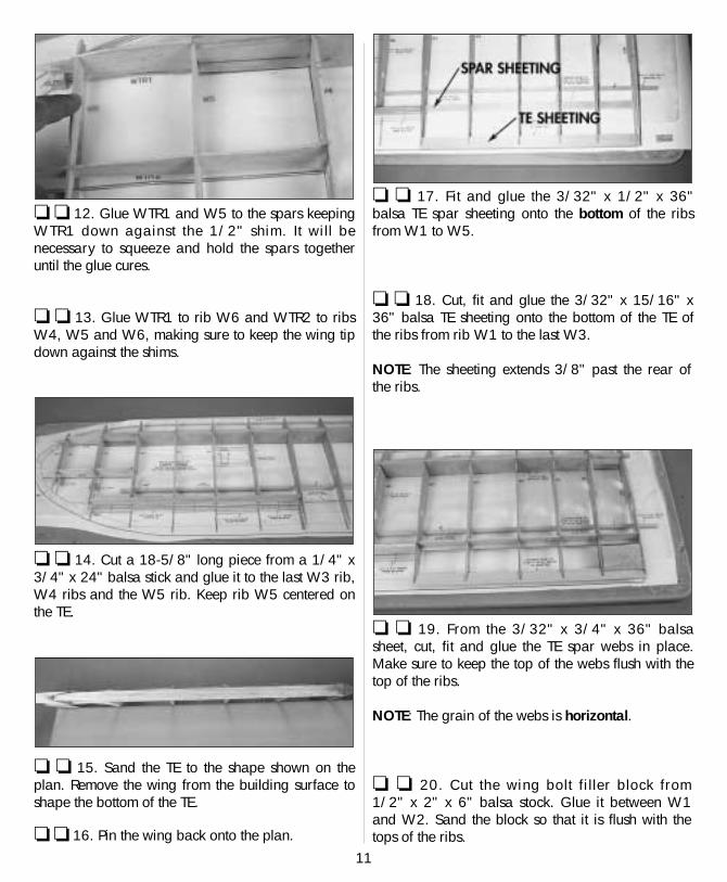
❏ 2. Glue the die-cut 1/8" ply W1D and W2Ddoublers to four W3 ribs with 6-minute epoxy asshown in the photo.
NOTE: The W1D landing gear notch is deeper thanthe notch in W2D.
❏ ❏ 3. Cover the left wing plan with wax paper.Pin the 1/4" x 3/8" x 36" basswood bottom sparinto place. Pin the 1/4" x 3/8" x 36" balsa buildingjig into place with the 1/4" side against the plan.
NOTE: In the following steps pin the rear of each ribto the 1/4" x 3/8" building jig as they are glued tothe spar.
❏ ❏ 4. Glue the center rib into place using thedihedral gauge to set the angle. Make sure the W1Ddoubler is toward the tip of the wing.
❏ ❏ 5. Glue the rib with the W2D rib doubler ontothe bottom spar. Make sure the W2D doubler istoward the root of the wing.
❏ ❏ 6. Glue the remaining W3 and W4 ribs to thespar keeping them 90 degrees to the work surfaceand aligned over the ribs on the plans.
NOTE: Do not glue ribs W5 and W6 at this time.
❏ ❏ 7. Glue the 1/4" x 3/8" x 36" basswood topspar into place.
❏ ❏ 8. From a sheet of 3/32" x 4" x 36" balsa cutand glue the shear webs into place.
IMPORTANT: Do not put shear webs between ribsW1 and W2 or between W2 and the first W3 onthe front of the spars.
❏ ❏ 9. Fit together but do not glue W5, W6,WTR1, and WTR2
❏ ❏ 10. Cut and pin two 1/2" shims and one3/4" shim in place.
❏ ❏ 11. Trim the top and bottom spars even withthe tip side of W5.
10
11
❏ ❏ 12. Glue WTR1 and W5 to the spars keepingWTR1 down against the 1/2" shim. It will benecessary to squeeze and hold the spars togetheruntil the glue cures.
❏ ❏ 13. Glue WTR1 to rib W6 and WTR2 to ribsW4, W5 and W6, making sure to keep the wing tipdown against the shims.
❏ ❏ 14. Cut a 18-5/8" long piece from a 1/4" x3/4" x 24" balsa stick and glue it to the last W3 rib,W4 ribs and the W5 rib. Keep rib W5 centered onthe TE.
❏ ❏ 15. Sand the TE to the shape shown on theplan. Remove the wing from the building surface toshape the bottom of the TE.
❏ ❏ 16. Pin the wing back onto the plan.
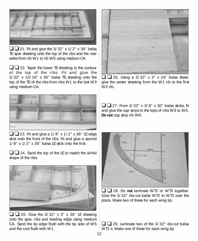
❏ ❏ 17. Fit and glue the 3/32" x 1/2" x 36"balsa TE spar sheeting onto the bottom of the ribsfrom W1 to W5.
❏ ❏ 18. Cut, fit and glue the 3/32" x 15/16" x36" balsa TE sheeting onto the bottom of the TE ofthe ribs from rib W1 to the last W3.
NOTE: The sheeting extends 3/8" past the rear ofthe ribs.
❏ ❏ 19. From the 3/32" x 3/4" x 36" balsasheet, cut, fit and glue the TE spar webs in place.Make sure to keep the top of the webs flush with thetop of the ribs.
NOTE: The grain of the webs is horizontal.
❏ ❏ 20. Cut the wing bolt filler block from 1/2" x 2" x 6" balsa stock. Glue it between W1and W2. Sand the block so that it is flush with thetops of the ribs.
12
❏ ❏ 21. Fit and glue the 3/32" x 1/2" x 36" balsaTE spar sheeting onto the top of the ribs and the rearwebs from rib W1 to rib W5 using medium CA.
❏ ❏ 22. Taper the lower TE sheeting to the contourof the top of the ribs. Fi t and glue the 3/32" x 15/16" x 36" balsa TE sheeting onto thetop of the TE of the ribs from ribs W1 to the last W3using medium CA.
❏ ❏ 23. Fit and glue a 1/8" x 1/2" x 36" LE edgestick onto the front of the ribs. Fit and glue a second1/8" x 1/2" x 36" balsa LE stick onto the first.
❏ ❏ 24. Sand the top of the LE to match the airfoilshape of the ribs.
❏ ❏ 25. Glue the 3/32" x 3" x 36" LE sheetingonto the spar, ribs and leading edge using mediumCA. Sand the tip edge flush with the tip side of W5and the root flush with W1.
❏ ❏ 26. Using a 3/32" x 3" x 24" balsa sheet,glue the center sheeting from the W1 rib to the firstW3 rib.
❏ ❏ 27. From 3/32" x 3/8" x 30" balsa sticks, fitand glue the cap strips to the tops of ribs W3 to W5.Do not cap strip rib W6.
❏ ❏ 28. Do not laminate WT2 or WT3 together.Glue the 3/32" die-cut balsa WT2 to WT3 over theplans. Make two of these for each wing tip.
❏ ❏ 29. Laminate two of the 3/32" die-cut balsaWT1's. Make one of these for each wing tip.
13
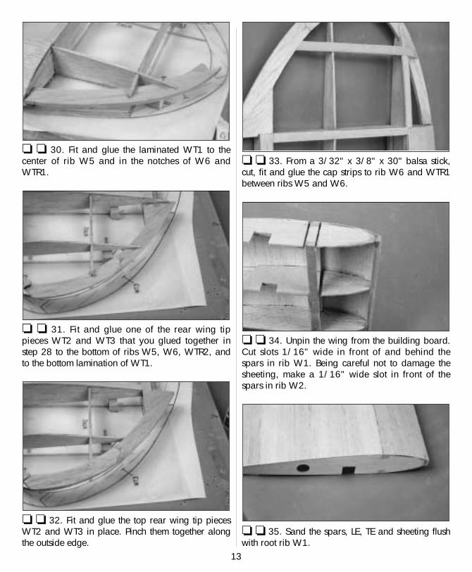
❏ ❏ 30. Fit and glue the laminated WT1 to thecenter of rib W5 and in the notches of W6 andWTR1.
❏ ❏ 31. Fit and glue one of the rear wing tippieces WT2 and WT3 that you glued together instep 28 to the bottom of ribs W5, W6, WTR2, andto the bottom lamination of WT1.
❏ ❏ 32. Fit and glue the top rear wing tip piecesWT2 and WT3 in place. Pinch them together alongthe outside edge.
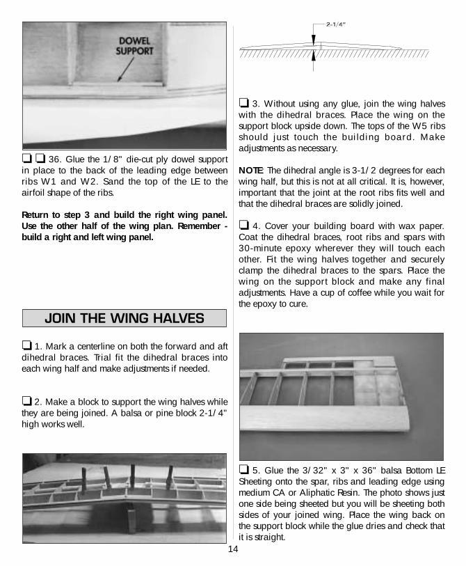
❏ ❏ 33. From a 3/32" x 3/8" x 30" balsa stick,cut, fit and glue the cap strips to rib W6 and WTR1between ribs W5 and W6.
❏ ❏ 34. Unpin the wing from the building board.Cut slots 1/16" wide in front of and behind thespars in rib W1. Being careful not to damage thesheeting, make a 1/16" wide slot in front of thespars in rib W2.
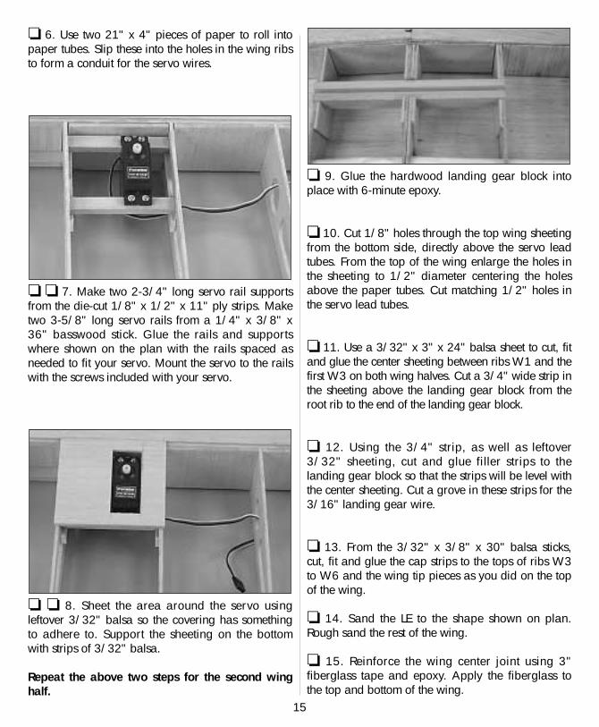
❏ ❏ 35. Sand the spars, LE, TE and sheeting flushwith root rib W1.
14
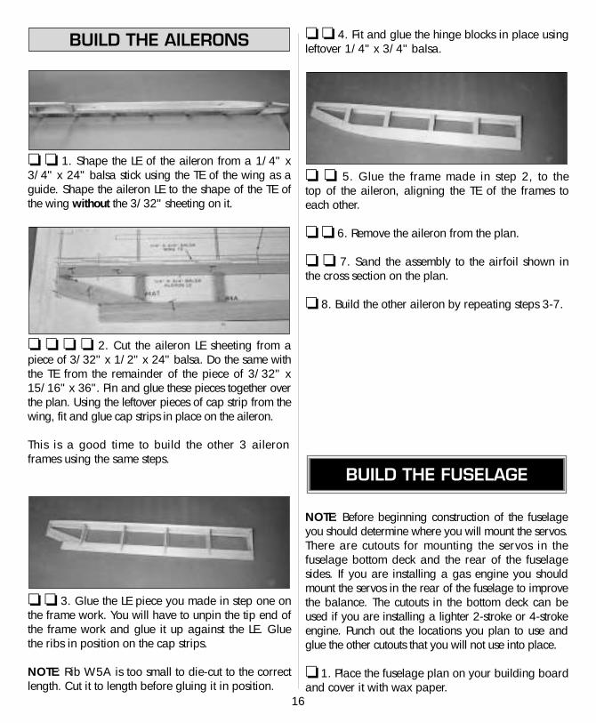
❏ ❏ 36. Glue the 1/8" die-cut ply dowel supportin place to the back of the leading edge betweenribs W1 and W2. Sand the top of the LE to theairfoil shape of the ribs.
Return to step 3 and build the right wing panel.Use the other half of the wing plan. Remember -build a right and left wing panel.
❏ 1. Mark a centerline on both the forward and aftdihedral braces. Trial fit the dihedral braces intoeach wing half and make adjustments if needed.
❏ 2. Make a block to support the wing halves whilethey are being joined. A balsa or pine block 2-1/4"high works well.
❏ 3. Without using any glue, join the wing halveswith the dihedral braces. Place the wing on thesupport block upside down. The tops of the W5 ribsshould just touch the building board. Makeadjustments as necessary.
NOTE: The dihedral angle is 3-1/2 degrees for eachwing half, but this is not at all critical. It is, however,important that the joint at the root ribs fits well andthat the dihedral braces are solidly joined.
❏ 4. Cover your building board with wax paper.Coat the dihedral braces, root ribs and spars with30-minute epoxy wherever they will touch eachother. Fit the wing halves together and securelyclamp the dihedral braces to the spars. Place thewing on the support block and make any finaladjustments. Have a cup of coffee while you wait forthe epoxy to cure.
❏ 5. Glue the 3/32" x 3" x 36" balsa Bottom LESheeting onto the spar, ribs and leading edge usingmedium CA or Aliphatic Resin. The photo shows justone side being sheeted but you will be sheeting bothsides of your joined wing. Place the wing back onthe support block while the glue dries and check thatit is straight.
JOIN THE WING HALVES
15
❏ 6. Use two 21" x 4" pieces of paper to roll intopaper tubes. Slip these into the holes in the wing ribsto form a conduit for the servo wires.
❏ ❏ 7. Make two 2-3/4" long servo rail supportsfrom the die-cut 1/8" x 1/2" x 11" ply strips. Maketwo 3-5/8" long servo rails from a 1/4" x 3/8" x36" basswood stick. Glue the rails and supportswhere shown on the plan with the rails spaced asneeded to fit your servo. Mount the servo to the railswith the screws included with your servo.
❏ ❏ 8. Sheet the area around the servo usingleftover 3/32" balsa so the covering has somethingto adhere to. Support the sheeting on the bottomwith strips of 3/32" balsa.
Repeat the above two steps for the second winghalf.
❏ 9. Glue the hardwood landing gear block intoplace with 6-minute epoxy.
❏ 10. Cut 1/8" holes through the top wing sheetingfrom the bottom side, directly above the servo leadtubes. From the top of the wing enlarge the holes inthe sheeting to 1/2" diameter centering the holesabove the paper tubes. Cut matching 1/2" holes inthe servo lead tubes.
❏ 11. Use a 3/32" x 3" x 24" balsa sheet to cut, fitand glue the center sheeting between ribs W1 and thefirst W3 on both wing halves. Cut a 3/4" wide strip inthe sheeting above the landing gear block from theroot rib to the end of the landing gear block.
❏ 12. Using the 3/4" strip, as well as leftover3/32" sheeting, cut and glue filler strips to thelanding gear block so that the strips will be level withthe center sheeting. Cut a grove in these strips for the3/16" landing gear wire.
❏ 13. From the 3/32" x 3/8" x 30" balsa sticks,cut, fit and glue the cap strips to the tops of ribs W3to W6 and the wing tip pieces as you did on the topof the wing.
❏ 14. Sand the LE to the shape shown on plan.Rough sand the rest of the wing.
❏ 15. Reinforce the wing center joint using 3"fiberglass tape and epoxy. Apply the fiberglass tothe top and bottom of the wing.
16
❏ ❏ 1. Shape the LE of the aileron from a 1/4" x3/4" x 24" balsa stick using the TE of the wing as aguide. Shape the aileron LE to the shape of the TE ofthe wing without the 3/32" sheeting on it.
❏ ❏ ❏ ❏ 2. Cut the aileron LE sheeting from apiece of 3/32" x 1/2" x 24" balsa. Do the same withthe TE from the remainder of the piece of 3/32" x15/16" x 36". Pin and glue these pieces together overthe plan. Using the leftover pieces of cap strip from thewing, fit and glue cap strips in place on the aileron.
This is a good time to build the other 3 aileronframes using the same steps.
❏ ❏ 3. Glue the LE piece you made in step one onthe frame work. You will have to unpin the tip end ofthe frame work and glue it up against the LE. Gluethe ribs in position on the cap strips.
NOTE: Rib W5A is too small to die-cut to the correctlength. Cut it to length before gluing it in position.
❏ ❏ 4. Fit and glue the hinge blocks in place usingleftover 1/4" x 3/4" balsa.
❏ ❏ 5. Glue the frame made in step 2, to the top of the aileron, aligning the TE of the frames toeach other.
❏ ❏ 6. Remove the aileron from the plan.
❏ ❏ 7. Sand the assembly to the airfoil shown inthe cross section on the plan.
❏ 8. Build the other aileron by repeating steps 3-7.
NOTE: Before beginning construction of the fuselageyou should determine where you will mount the servos.There are cutouts for mounting the servos in thefuselage bottom deck and the rear of the fuselagesides. If you are installing a gas engine you shouldmount the servos in the rear of the fuselage to improvethe balance. The cutouts in the bottom deck can beused if you are installing a lighter 2-stroke or 4-strokeengine. Punch out the locations you plan to use andglue the other cutouts that you will not use into place.
❏ 1. Place the fuselage plan on your building boardand cover it with wax paper.
BUILD THE FUSELAGE
BUILD THE AILERONS
17
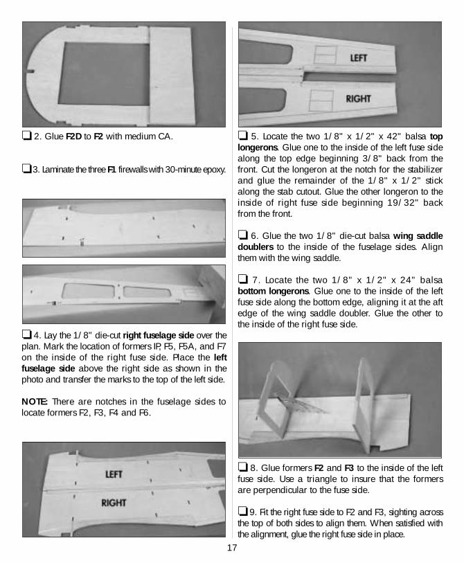
❏ 2. Glue F2D to F2 with medium CA.
❏ 3. Laminate the three F1 firewalls with 30-minute epoxy.
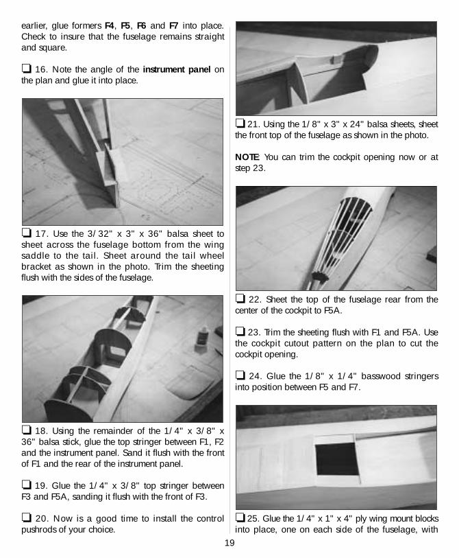
❏ 4. Lay the 1/8" die-cut right fuselage side over theplan. Mark the location of formers IP, F5, F5A, and F7on the inside of the right fuse side. Place the leftfuselage side above the right side as shown in thephoto and transfer the marks to the top of the left side.
NOTE: There are notches in the fuselage sides tolocate formers F2, F3, F4 and F6.
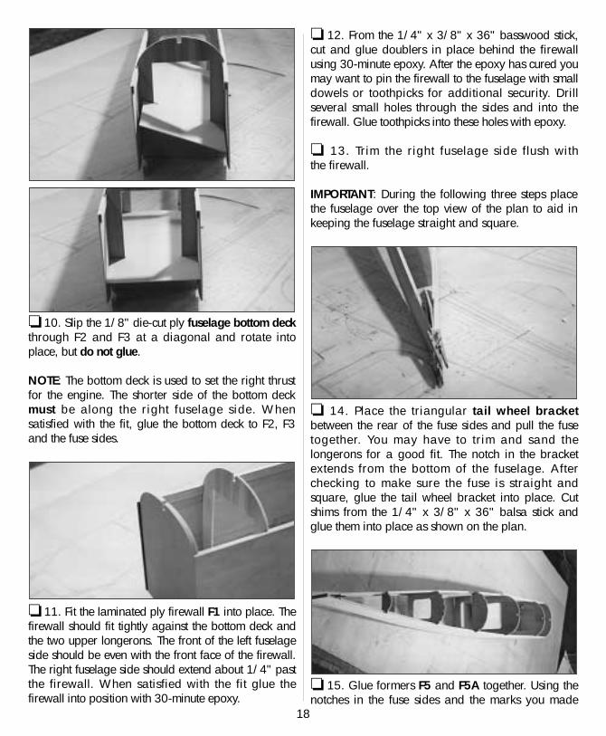
❏ 5. Locate the two 1/8" x 1/2" x 42" balsa toplongerons. Glue one to the inside of the left fuse sidealong the top edge beginning 3/8" back from thefront. Cut the longeron at the notch for the stabilizerand glue the remainder of the 1/8" x 1/2" stickalong the stab cutout. Glue the other longeron to theinside of right fuse side beginning 19/32" backfrom the front.
❏ 6. Glue the two 1/8" die-cut balsa wing saddledoublers to the inside of the fuselage sides. Alignthem with the wing saddle.
❏ 7. Locate the two 1/8" x 1/2" x 24" balsabottom longerons. Glue one to the inside of the leftfuse side along the bottom edge, aligning it at the aftedge of the wing saddle doubler. Glue the other tothe inside of the right fuse side.
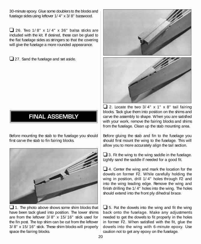
❏ 8. Glue formers F2 and F3 to the inside of the leftfuse side. Use a triangle to insure that the formersare perpendicular to the fuse side.
❏ 9. Fit the right fuse side to F2 and F3, sighting acrossthe top of both sides to align them. When satisfied withthe alignment, glue the right fuse side in place.
18
❏ 10. Slip the 1/8" die-cut ply fuselage bottom deckthrough F2 and F3 at a diagonal and rotate intoplace, but do not glue.
NOTE: The bottom deck is used to set the right thrustfor the engine. The shorter side of the bottom deckmust be along the right fuselage side. Whensatisfied with the fit, glue the bottom deck to F2, F3and the fuse sides.
❏ 11. Fit the laminated ply firewall F1 into place. Thefirewall should fit tightly against the bottom deck andthe two upper longerons. The front of the left fuselageside should be even with the front face of the firewall.The right fuselage side should extend about 1/4" pastthe firewall. When satisfied with the fit glue thefirewall into position with 30-minute epoxy.
❏ 12. From the 1/4" x 3/8" x 36" basswood stick,cut and glue doublers in place behind the firewallusing 30-minute epoxy. After the epoxy has cured youmay want to pin the firewall to the fuselage with smalldowels or toothpicks for additional security. Drillseveral small holes through the sides and into thefirewall. Glue toothpicks into these holes with epoxy.
❏ 13. Trim the right fuselage side flush with the firewall.
IMPORTANT: During the following three steps placethe fuselage over the top view of the plan to aid inkeeping the fuselage straight and square.
❏ 14. Place the triangular tail wheel bracketbetween the rear of the fuse sides and pull the fusetogether. You may have to trim and sand thelongerons for a good fit. The notch in the bracketextends from the bottom of the fuselage. Afterchecking to make sure the fuse is straight andsquare, glue the tail wheel bracket into place. Cutshims from the 1/4" x 3/8" x 36" balsa stick andglue them into place as shown on the plan.
❏ 15. Glue formers F5 and F5A together. Using thenotches in the fuse sides and the marks you made
19
earlier, glue formers F4, F5, F6 and F7 into place.Check to insure that the fuselage remains straightand square.
❏ 16. Note the angle of the instrument panel onthe plan and glue it into place.
❏ 17. Use the 3/32" x 3" x 36" balsa sheet tosheet across the fuselage bottom from the wingsaddle to the tail. Sheet around the tail wheelbracket as shown in the photo. Trim the sheetingflush with the sides of the fuselage.
❏ 18. Using the remainder of the 1/4" x 3/8" x36" balsa stick, glue the top stringer between F1, F2and the instrument panel. Sand it flush with the frontof F1 and the rear of the instrument panel.
❏ 19. Glue the 1/4" x 3/8" top stringer betweenF3 and F5A, sanding it flush with the front of F3.
❏ 20. Now is a good time to install the controlpushrods of your choice.
❏ 21. Using the 1/8" x 3" x 24" balsa sheets, sheetthe front top of the fuselage as shown in the photo.
NOTE: You can trim the cockpit opening now or atstep 23.
❏ 22. Sheet the top of the fuselage rear from thecenter of the cockpit to F5A.
❏ 23. Trim the sheeting flush with F1 and F5A. Usethe cockpit cutout pattern on the plan to cut thecockpit opening.
❏ 24. Glue the 1/8" x 1/4" basswood stringersinto position between F5 and F7.
❏ 25. Glue the 1/4" x 1" x 4" ply wing mount blocksinto place, one on each side of the fuselage, with
30-minute epoxy. Glue some doublers to the blocks andfuselage sides using leftover 1/4" x 3/8" basswood.
❏ 26. Two 1/8" x 1/4" x 36" balsa sticks areincluded with the kit. If desired, these can be glued tothe flat fuselage sides as stringers so that the coveringwill give the fuselage a more rounded appearance.
❏ 27. Sand the fuselage and set aside.
Before mounting the stab to the fuselage you shouldfirst carve the stab to fin fairing blocks.
❏ 1. The photo above shows some shim blocks thathave been tack glued into position. The lower shimsare from the leftover 3/8" x 15/16" stick used forthe fin post. The top shim can be cut from the leftover3/8" x 15/16" stick. These shim blocks will properlyspace the fairing blocks.
❏ 2. Locate the two 3/4" x 1" x 8" tail fairingblocks. Tack glue them into position on the shims andcarve the assembly to shape. When you are satisfiedwith your work, remove the fairing blocks and shimsfrom the fuselage. Clean up the stab mounting area.
Before gluing the stab and fin to the fuselage youshould first mount the wing to the fuselage. This willallow you to more accurately align the tail section.
❏ 3. Fit the wing to the wing saddle in the fuselage.Lightly sand the saddle if needed for a good fit.
❏ 4. Center the wing and mark the location for thedowels on former F2. While carefully holding thewing in position, drill 1/4" holes through F2 andinto the wing leading edge. Remove the wing andfinish drilling the 1/4" holes into the wing. The holesshould extend into the front ply dihedral brace.
❏ 5. Put the dowels into the wing and fit the wingback onto the fuselage. Make any adjustmentsneeded to get the dowels to fit properly in the holesin former F2. When satisfied with the fit, glue thedowels into the wing with 6-minute epoxy. Usecaution not to get any epoxy on the fuselage.
FINAL ASSEMBLY
20
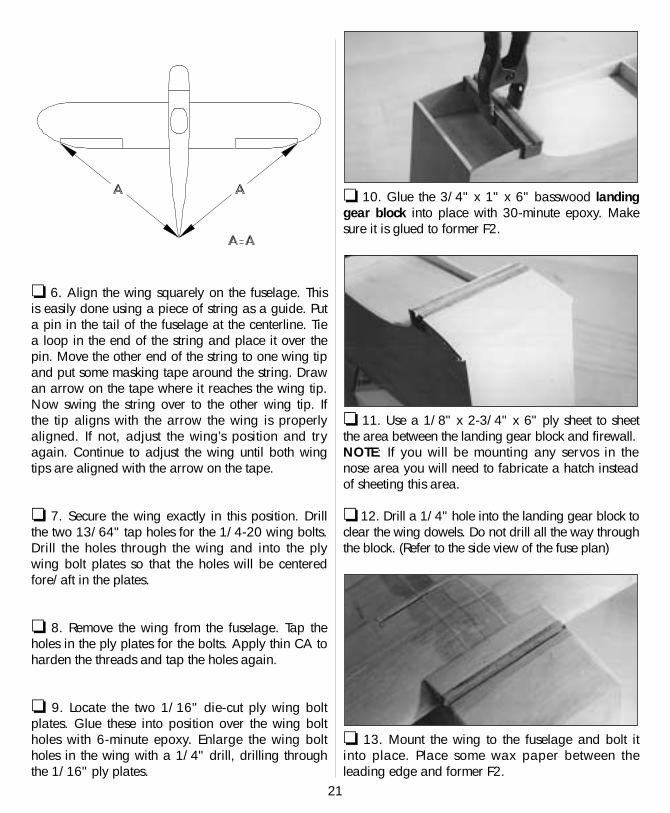
❏ 6. Align the wing squarely on the fuselage. Thisis easily done using a piece of string as a guide. Puta pin in the tail of the fuselage at the centerline. Tiea loop in the end of the string and place it over thepin. Move the other end of the string to one wing tipand put some masking tape around the string. Drawan arrow on the tape where it reaches the wing tip.Now swing the string over to the other wing tip. Ifthe tip aligns with the arrow the wing is properlyaligned. If not, adjust the wing’s position and tryagain. Continue to adjust the wing until both wingtips are aligned with the arrow on the tape.
❏ 7. Secure the wing exactly in this position. Drillthe two 13/64" tap holes for the 1/4-20 wing bolts.Drill the holes through the wing and into the plywing bolt plates so that the holes will be centeredfore/aft in the plates.
❏ 8. Remove the wing from the fuselage. Tap theholes in the ply plates for the bolts. Apply thin CA toharden the threads and tap the holes again.
❏ 9. Locate the two 1/16" die-cut ply wing boltplates. Glue these into position over the wing boltholes with 6-minute epoxy. Enlarge the wing boltholes in the wing with a 1/4" drill, drilling throughthe 1/16" ply plates.
❏ 10. Glue the 3/4" x 1" x 6" basswood landinggear block into place with 30-minute epoxy. Makesure it is glued to former F2.
❏ 11. Use a 1/8" x 2-3/4" x 6" ply sheet to sheetthe area between the landing gear block and firewall.NOTE: If you will be mounting any servos in thenose area you will need to fabricate a hatch insteadof sheeting this area.
❏ 12. Drill a 1/4" hole into the landing gear block toclear the wing dowels. Do not drill all the way throughthe block. (Refer to the side view of the fuse plan)
❏ 13. Mount the wing to the fuselage and bolt itinto place. Place some wax paper between theleading edge and former F2.
21
❏ 14. Use the remainder of the 3/8" x 15/16"stick to make a fairing between the bottom of thewing and former F2.
❏ 15. You can now glue the stab and fin to thefuselage. To increase the gluing area, glue someleftover 3/8" stick to the inside of the fuselage sidesat the stab saddle.
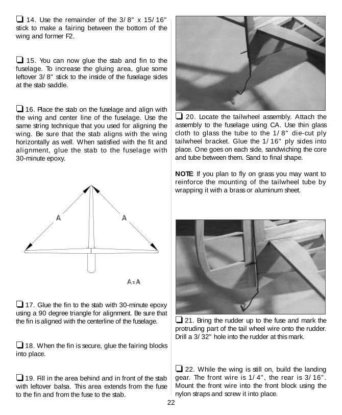
❏ 16. Place the stab on the fuselage and align withthe wing and center line of the fuselage. Use thesame string technique that you used for aligning thewing. Be sure that the stab aligns with the winghorizontally as well. When satisfied with the fit andalignment, glue the stab to the fuselage with 30-minute epoxy.
❏ 17. Glue the fin to the stab with 30-minute epoxyusing a 90 degree triangle for alignment. Be sure thatthe fin is aligned with the centerline of the fuselage.
❏ 18. When the fin is secure, glue the fairing blocksinto place.
❏ 19. Fill in the area behind and in front of the stabwith leftover balsa. This area extends from the fuseto the fin and from the fuse to the stab.
❏ 20. Locate the tailwheel assembly. Attach theassembly to the fuselage using CA. Use thin glasscloth to glass the tube to the 1/8" die-cut plytailwheel bracket. Glue the 1/16" ply sides intoplace. One goes on each side, sandwiching the coreand tube between them. Sand to final shape.
NOTE: If you plan to fly on grass you may want toreinforce the mounting of the tailwheel tube bywrapping it with a brass or aluminum sheet.
❏ 21. Bring the rudder up to the fuse and mark theprotruding part of the tail wheel wire onto the rudder.Drill a 3/32" hole into the rudder at this mark.
❏ 22. While the wing is still on, build the landinggear. The front wire is 1/4", the rear is 3/16".Mount the front wire into the front block using thenylon straps and screw it into place.
22
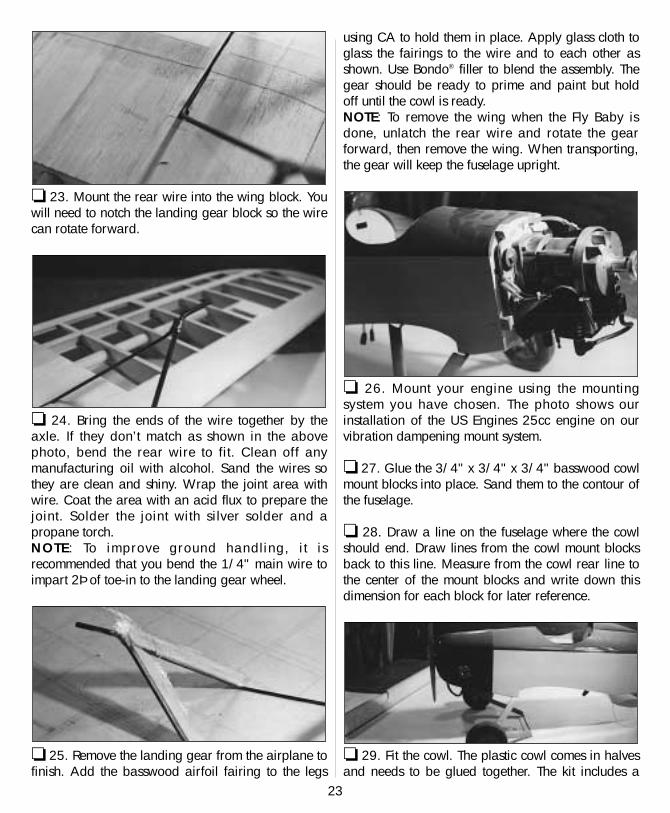
❏ 23. Mount the rear wire into the wing block. Youwill need to notch the landing gear block so the wirecan rotate forward.
❏ 24. Bring the ends of the wire together by theaxle. If they don’t match as shown in the abovephoto, bend the rear wire to fit. Clean off anymanufacturing oil with alcohol. Sand the wires sothey are clean and shiny. Wrap the joint area withwire. Coat the area with an acid flux to prepare thejoint. Solder the joint with silver solder and apropane torch.NOTE: To improve ground handling, i t isrecommended that you bend the 1/4" main wire toimpart 2Þ of toe-in to the landing gear wheel.
❏ 25. Remove the landing gear from the airplane tofinish. Add the basswood airfoil fairing to the legs
using CA to hold them in place. Apply glass cloth toglass the fairings to the wire and to each other asshown. Use Bondo® filler to blend the assembly. Thegear should be ready to prime and paint but holdoff until the cowl is ready.NOTE: To remove the wing when the Fly Baby isdone, unlatch the rear wire and rotate the gearforward, then remove the wing. When transporting,the gear will keep the fuselage upright.
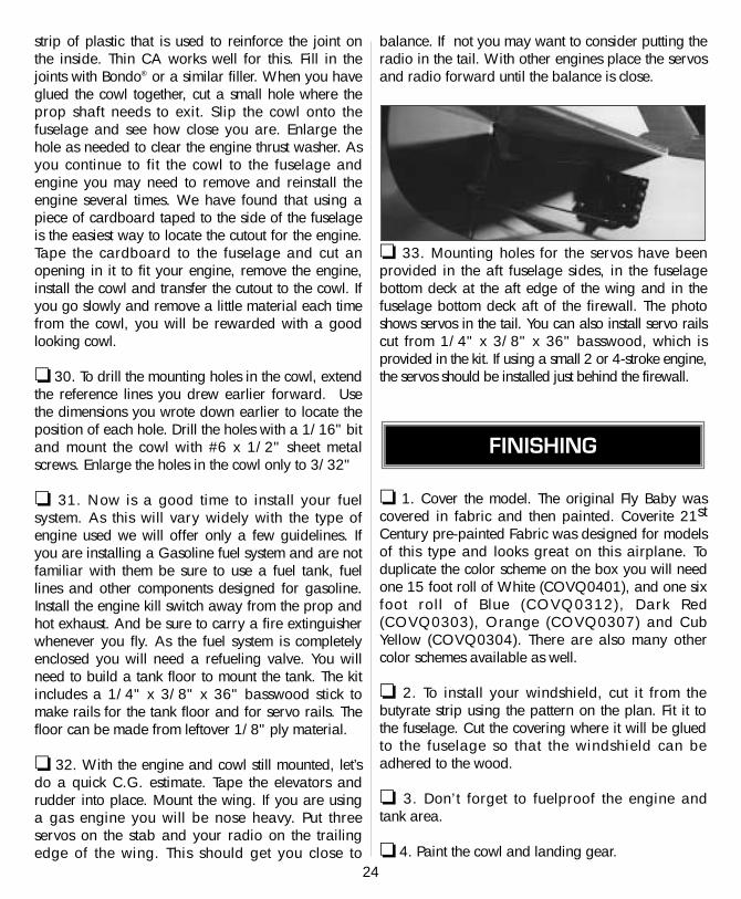
❏ 26. Mount your engine using the mountingsystem you have chosen. The photo shows ourinstallation of the US Engines 25cc engine on ourvibration dampening mount system.
❏ 27. Glue the 3/4" x 3/4" x 3/4" basswood cowlmount blocks into place. Sand them to the contour ofthe fuselage.
❏ 28. Draw a line on the fuselage where the cowlshould end. Draw lines from the cowl mount blocksback to this line. Measure from the cowl rear line tothe center of the mount blocks and write down thisdimension for each block for later reference.
❏ 29. Fit the cowl. The plastic cowl comes in halvesand needs to be glued together. The kit includes a
23
strip of plastic that is used to reinforce the joint onthe inside. Thin CA works well for this. Fill in thejoints with Bondo® or a similar filler. When you haveglued the cowl together, cut a small hole where theprop shaft needs to exit. Slip the cowl onto thefuselage and see how close you are. Enlarge thehole as needed to clear the engine thrust washer. Asyou continue to fit the cowl to the fuselage andengine you may need to remove and reinstall theengine several times. We have found that using apiece of cardboard taped to the side of the fuselageis the easiest way to locate the cutout for the engine.Tape the cardboard to the fuselage and cut anopening in it to fit your engine, remove the engine,install the cowl and transfer the cutout to the cowl. Ifyou go slowly and remove a little material each timefrom the cowl, you will be rewarded with a goodlooking cowl.
❏ 30. To drill the mounting holes in the cowl, extendthe reference lines you drew earlier forward. Usethe dimensions you wrote down earlier to locate theposition of each hole. Drill the holes with a 1/16" bitand mount the cowl with #6 x 1/2" sheet metalscrews. Enlarge the holes in the cowl only to 3/32"
❏ 31. Now is a good time to install your fuelsystem. As this will vary widely with the type ofengine used we will offer only a few guidelines. Ifyou are installing a Gasoline fuel system and are notfamiliar with them be sure to use a fuel tank, fuellines and other components designed for gasoline.Install the engine kill switch away from the prop andhot exhaust. And be sure to carry a fire extinguisherwhenever you fly. As the fuel system is completelyenclosed you will need a refueling valve. You willneed to build a tank floor to mount the tank. The kitincludes a 1/4" x 3/8" x 36" basswood stick tomake rails for the tank floor and for servo rails. Thefloor can be made from leftover 1/8" ply material.
❏ 32. With the engine and cowl still mounted, let’sdo a quick C.G. estimate. Tape the elevators andrudder into place. Mount the wing. If you are usinga gas engine you will be nose heavy. Put threeservos on the stab and your radio on the trailingedge of the wing. This should get you close to
balance. If not you may want to consider putting theradio in the tail. With other engines place the servosand radio forward until the balance is close.
❏ 33. Mounting holes for the servos have beenprovided in the aft fuselage sides, in the fuselagebottom deck at the aft edge of the wing and in thefuselage bottom deck aft of the firewall. The photoshows servos in the tail. You can also install servo railscut from 1/4" x 3/8" x 36" basswood, which isprovided in the kit. If using a small 2 or 4-stroke engine,the servos should be installed just behind the firewall.
❏ 1. Cover the model. The original Fly Baby wascovered in fabric and then painted. Coverite 21stCentury pre-painted Fabric was designed for modelsof this type and looks great on this airplane. Toduplicate the color scheme on the box you will needone 15 foot roll of White (COVQ0401), and one sixfoot rol l of Blue (COVQ0312), Dark Red(COVQ0303), Orange (COVQ0307) and CubYellow (COVQ0304). There are also many othercolor schemes available as well.
❏ 2. To install your windshield, cut it from thebutyrate strip using the pattern on the plan. Fit it tothe fuselage. Cut the covering where it will be gluedto the fuselage so that the windshield can beadhered to the wood.
❏ 3. Don’t forget to fuelproof the engine and tank area.
❏ 4. Paint the cowl and landing gear.
FINISHING
24
❏ 5. Mount the wheels.
❏ 6. Hinge the rudder, elevators and ailerons with theheavy-duty hinges you have chosen.
❏ 7. Mount the control horns onto the rudder,elevator, and ailerons.
❏ 8. Install the radio system. Our radio installationconsisted of the following:
A.We used one hi-torque servo for each aileron.B.We used one hi-torque servo for each elevator,
with a separate pushrod for each.C.We used one hi-torque servo for the rudder.D.We used a standard servo for the throttle.E. We used a 1200 Mah battery pack to allow for
the additional servo drain.
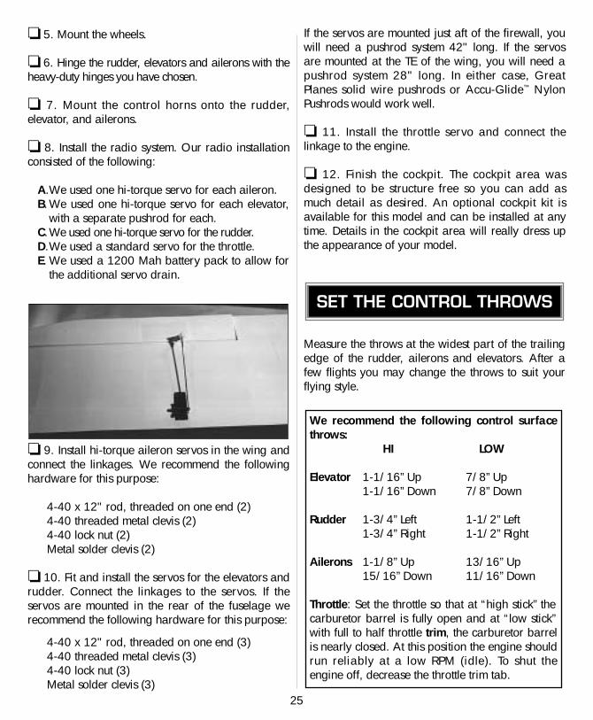
❏ 9. Install hi-torque aileron servos in the wing andconnect the linkages. We recommend the followinghardware for this purpose:
4-40 x 12" rod, threaded on one end (2)4-40 threaded metal clevis (2)4-40 lock nut (2)Metal solder clevis (2)
❏ 10. Fit and install the servos for the elevators andrudder. Connect the linkages to the servos. If theservos are mounted in the rear of the fuselage werecommend the following hardware for this purpose:
4-40 x 12" rod, threaded on one end (3)4-40 threaded metal clevis (3)4-40 lock nut (3)Metal solder clevis (3)
If the servos are mounted just aft of the firewall, youwill need a pushrod system 42" long. If the servosare mounted at the TE of the wing, you will need apushrod system 28" long. In either case, GreatPlanes solid wire pushrods or Accu-Glide™ NylonPushrods would work well.
❏ 11. Install the throttle servo and connect thelinkage to the engine.
❏ 12. Finish the cockpit. The cockpit area wasdesigned to be structure free so you can add asmuch detail as desired. An optional cockpit kit isavailable for this model and can be installed at anytime. Details in the cockpit area will really dress upthe appearance of your model.
Measure the throws at the widest part of the trailingedge of the rudder, ailerons and elevators. After afew flights you may change the throws to suit yourflying style.
We recommend the following control surfacethrows:
HI LOW
Elevator 1-1/16” Up 7/8” Up1-1/16” Down 7/8” Down
Rudder 1-3/4” Left 1-1/2” Left1-3/4” Right 1-1/2” Right
Ailerons 1-1/8” Up 13/16” Up15/16” Down 11/16” Down
Throttle: Set the throttle so that at “high stick” thecarburetor barrel is fully open and at “low stick”with full to half throttle trim, the carburetor barrelis nearly closed. At this position the engine shouldrun reliably at a low RPM (idle). To shut theengine off, decrease the throttle trim tab.
SET THE CONTROL THROWS
25
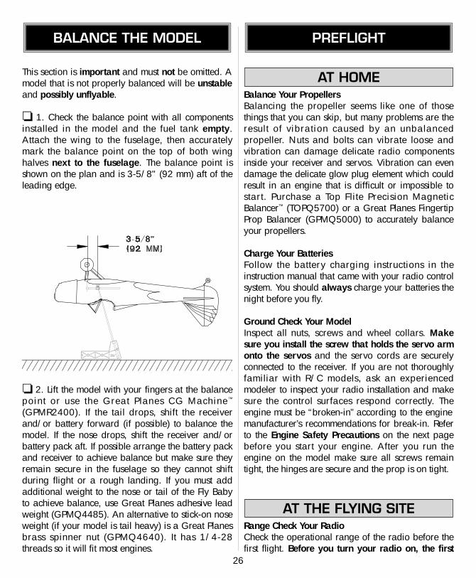
This section is important and must not be omitted. Amodel that is not properly balanced will be unstableand possibly unflyable.
❏ 1. Check the balance point with all componentsinstalled in the model and the fuel tank empty.Attach the wing to the fuselage, then accuratelymark the balance point on the top of both winghalves next to the fuselage. The balance point isshown on the plan and is 3-5/8" (92 mm) aft of theleading edge.
❏ 2. Lift the model with your fingers at the balancepoint or use the Great Planes CG Machine™
(GPMR2400). If the tail drops, shift the receiverand/or battery forward (if possible) to balance themodel. If the nose drops, shift the receiver and/orbattery pack aft. If possible arrange the battery packand receiver to achieve balance but make sure theyremain secure in the fuselage so they cannot shiftduring flight or a rough landing. If you must addadditional weight to the nose or tail of the Fly Babyto achieve balance, use Great Planes adhesive leadweight (GPMQ4485). An alternative to stick-on noseweight (if your model is tail heavy) is a Great Planesbrass spinner nut (GPMQ4640). It has 1/4-28threads so it will fit most engines.
Balance Your PropellersBalancing the propeller seems like one of thosethings that you can skip, but many problems are theresult of vibration caused by an unbalancedpropeller. Nuts and bolts can vibrate loose andvibration can damage delicate radio componentsinside your receiver and servos. Vibration can evendamage the delicate glow plug element which couldresult in an engine that is difficult or impossible tostart. Purchase a Top Flite Precision MagneticBalancer™ (TOPQ5700) or a Great Planes FingertipProp Balancer (GPMQ5000) to accurately balanceyour propellers.
Charge Your BatteriesFollow the battery charging instructions in theinstruction manual that came with your radio controlsystem. You should always charge your batteries thenight before you fly.
Ground Check Your ModelInspect all nuts, screws and wheel collars. Makesure you install the screw that holds the servo armonto the servos and the servo cords are securelyconnected to the receiver. If you are not thoroughlyfamiliar with R/C models, ask an experiencedmodeler to inspect your radio installation and makesure the control surfaces respond correctly. Theengine must be “broken-in” according to the enginemanufacturer’s recommendations for break-in. Referto the Engine Safety Precautions on the next pagebefore you start your engine. After you run theengine on the model make sure all screws remaintight, the hinges are secure and the prop is on tight.
Range Check Your RadioCheck the operational range of the radio before thefirst flight. Before you turn your radio on, the first
AT THE FLYING SITE
AT HOME
PREFLIGHTBALANCE THE MODEL
26
thing you always must do is make sure no one elseis on your frequency (channel). Most model flyingfields utilize frequency control so familiarize yourselfwith their system. Collapse your transmitter antennaand turn on the transmitter first, then the receiver(preferably the receiver should never be on by itself).You should be able to walk at least 100 feet awayfrom the model and still have control. Have anassistant stand by your model and tell you what thecontrol surfaces are doing while you operate themfrom the transmitter. Repeat this test with an assistantholding the model and the engine running atvarious speeds. If the control surfaces do not alwaysrespond correctly, don’t fly! Find and correct theproblem first. Look for loose servo connections orcorrosion, loose fasteners that may cause vibration,a defective on/off switch, low battery voltage or adefective cell, a damaged receiver antenna or areceiver crystal that may have been damaged froma previous crash.
NOTE: Failure to follow these safety precautions maycause severe injury to yourself and others.
Store model fuel in a safe place away from highheat, sparks or flames. Do not smoke near theengine or fuel as it is very flammable. Engineexhaust gives off a great deal of deadly carbonmonoxide so do not run the engine in a closedroom or garage.
Get help from an experienced modeler when youlearn to operate engines.
Use safety glasses when you operate model engines.
Do not run the engine near loose gravel or sand; thepropeller may throw loose material in your face or eyes.
When you start and run the engine keep your faceand body as well as all spectators away from theplane of rotation of the propeller.
Keep loose clothing, shirt sleeves, ties, scarfs, longhair or loose objects away from the prop. Beconscious of pencils, screwdrivers or other objectsthat may fall out of your shirt or jacket pockets.
Use a “chicken stick” or electric starter and followthe instructions to start your engine.
Ask an assistant to hold the model from the rearwhile you start the engine and operate the controls.
Make all engine adjustments from behind therotating propeller.
The engine gets hot! Do not touch the engine duringor immediately after you operate it. Make sure fuellines are in good condition so fuel will not leak ontoa hot engine and cause a fire.
To stop the engine, close the carburetor barrel (rotor)or pinch the fuel line to discontinue the fuel flow. Donot use your hands, fingers or any body part to stopthe engine. Never throw anything into the prop of arunning engine.
The best place to fly your R/C model is at an AMA(Academy of Model Aeronautics) chartered clubfield. Ask your hobby dealer or the AMA if there isa club in your area and join it (the address andtelephone number for the AMA is listed on page 3of this instruction book). Club fields exist to makeyour R/C flying safe and enjoyable. We recommendthat you join the AMA and a local club so you mayhave a safe place to fly and insurance in case of aflying accident.
If a club flying site is not available, find a large, grassyarea at least 6 miles away from houses, buildings,streets and other R/C activity like boats and cars.Avoid flying R/C models near traffic or areas such as
FIND A SAFE PLACE TO FLY
FLIGHT
ENGINE SAFETY PRECAUTIONS
27
parks, school yards, office building lawns, etc. thatmay attract unrestrained observers (wild kids). If youare a beginner, you are busy enough concentrating onyour model without having to answer lots of questionsand performing crowd control.
We highly recommend that you get an experiencedmodeler to assist you with your flight training. Anexperienced modeler can take your Fly Baby up forthe first time and make sure it performs correctly, thengive you valuable flight instruction. He can hand youthe transmitter when the Fly Baby has climbed to asafe altitude or connect your transmitter to his if bothof your systems have a trainer cord or “buddy box”capability. Assistance from an experienced modelerwill make your modeling “career” progress faster(and cheaper). We do, however realize that somemodelers are determined to learn on their own or arenot in a location where an instructor or flying club isavailable. Therefore, we have provided the followinginformation to give you an idea of what to expect onyour first flight with your Fly Baby. Both flyers whoplan to set out on their own and fliers who will havethe help of an instructor should carefully read thefollowing information.
First flight attempts should be reserved for calm dayswhen the wind speed is less than five mph. Alwaystakeof f (and land) into the wind. Check theoperation of all controls just before takeoff. This willeliminate the possibility of overlooking reversed ordisconnected controls (it happens).
As you apply power on takeoff you will need toapply a slight amount of right rudder to compensatefor engine torque. Be ready for this and correct itsheading immediately to avoid an “exciting” take offroll. The tail will rise almost immediately, indicatingthat the tail surfaces have gained effectiveness.Allow the model to continue to accelerate until it hasreached flying speed. Use as much of the availablerunway as you can. Then, gently apply some upelevator. Your Fly Baby should slowly lift from therunway. Continue straight ahead until you haveaccelerated to a safe flying speed.
The design of the Fly Baby aircraft originated inmodel aviation of the early 1930’s, an era whenaviation was in it’s infancy. The Fly Baby model wasa high wing airplane that looked very much like thelater full scale Fly Baby, except for the placement ofthe wing. The full scale Fly Baby was designed foran EAA (Experimental Aircraft Association) contestthat had as it’s goal the development of easy tobuild, inexpensive, towable homebuilt aircraft. TheFly Baby was an all wood aircraft that could betypically built in 750 to 1000 hours.
The Fly Baby is a “sport” airplane. It’s not a PiperCub type aircraft, and it’s not an aerobatic Citabriaeither. It is a fun, easy to fly, forgiving aircraft that isideal for a Sunday flier to have a great day of opencockpit flying. The Fly Baby will perform scaleaerobatics such as loops, rolls, spins and stall turns.We encourage you to fly your Fly Baby in a scalemanner – slow and smoothly, like the real thing.Avoid unrealistic “hot dog” maneuvers that couldover-stress the structure. It will be easier on yourmodel and lot more enjoyable for you!
Before attempting your first landing you should firsttry some slow flight and stalls to become familiarwith the Fly Baby’s slow speed characteristics. Youwill probably find the model slows down quickerand requires more power on landing than you areused to. Remember that aircraft of the Fly Baby’s erahad high drag and limited low speed controleffectiveness, especially the ailerons. The rudder isvery effective however.
On landings, you will need to continue to carry powerand speed until you initiate the flare, then reducepower and allow the model to gently settle to theground. If you must go around, add power andaccelerate straight ahead. Do not attempt to climb orturn until you have accelerated to a safe flying speed.
We hope you enjoy the realist ic looks andperformance of your Fly Baby.
LANDING
FLYING
TAKEOFF


![READY-TO-FLY RADIO CONTROLLED MODEL AIRPLANEmanuals.hobbico.com/hca/hcaa12-manual.pdf · READY-TO-FLY RADIO CONTROLLED MODEL AIRPLANE Wingspan: 63 in [1600mm] ... avoid flying near](https://img.pdfslide.us/doc/110x75/5aa1266d7f8b9a8e178ef96e/ready-to-fly-radio-controlled-model-radio-controlled-model-airplane-wingspan-63.jpg)