Embed Size (px)
Citation preview
M. Christopher CottingDepartment of Aerospace and Ocean Engineering, VPISU
February 17, 2009
Senior Design Class
Aircraft Control Sizing
AOE Aircraft Design 02/17/09 Cotting 2
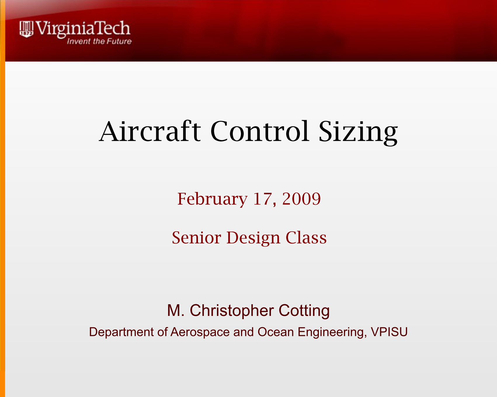
“If you are in trouble anywhere in the world, an airplane can fly over and drop flowers, but a helicopter can land and save your life.”
— Igor Sikorsky, 1947

AOE Aircraft Design 02/17/09 Cotting 3
AOE Aircraft Design 02/17/09 Cotting
Outline
Examples of Aircraft Control Surfaces
Balance (Trim and Equilibrium)
Stability (Static vs Dynamic Stability)
Maneuverability
4
AOE Aircraft Design 02/17/09 Cotting
Control Effectors
Effect change on an aircraft state, primarily through a moment imparted on an aircraft
May be part of a high lift system (in which case they may also change lift, which is a force...) or a throttle, which changes a force
In controls speak, a desired moment/force is commanded to an aircraft, it is then allocated according to the “B” matrix, and then effectors are commanded to impart that moment/force.
5
AOE Aircraft Design 02/17/09 Cotting
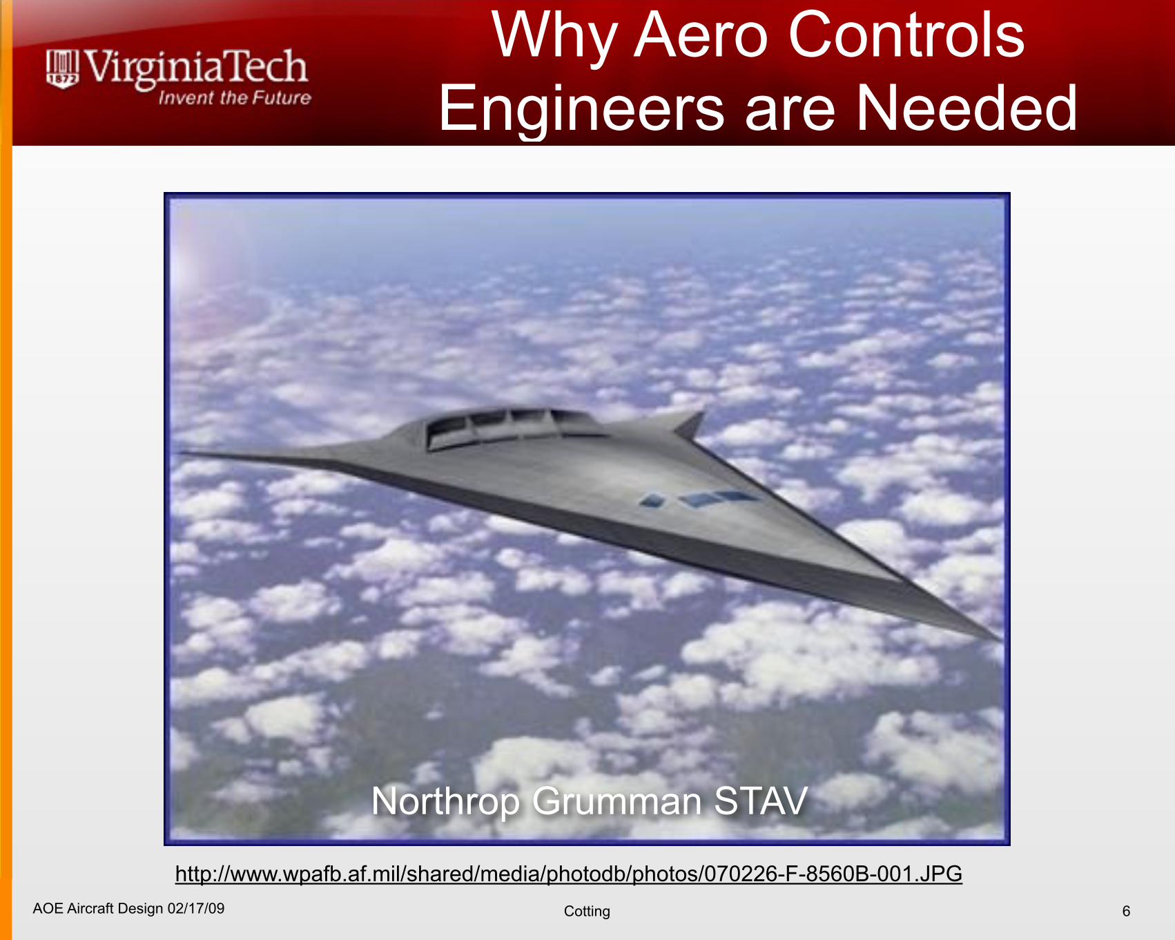
Why Aero Controls Engineers are Needed
6
http://www.wpafb.af.mil/shared/media/photodb/photos/070226-F-8560B-001.JPG
Northrop Grumman STAV
AOE Aircraft Design 02/17/09 Cotting
Why control effectors are bad
Create drag Add weight Reduce stealth Change the OML... Increase ground testing Can decrease reliability (increase risk) Add complexity
7
AOE Aircraft Design 02/17/09 Cotting
“I know it’s unstable, but it won’t trim!!!!!”
The aircraft must be balanced “Trimmed”
Each dynamic mode of aircraft motion must be:• stabalizable (stability) • controllable (maneuverability)
How many independent control effectors must we have?
8
AOE Aircraft Design 02/17/09 Cotting
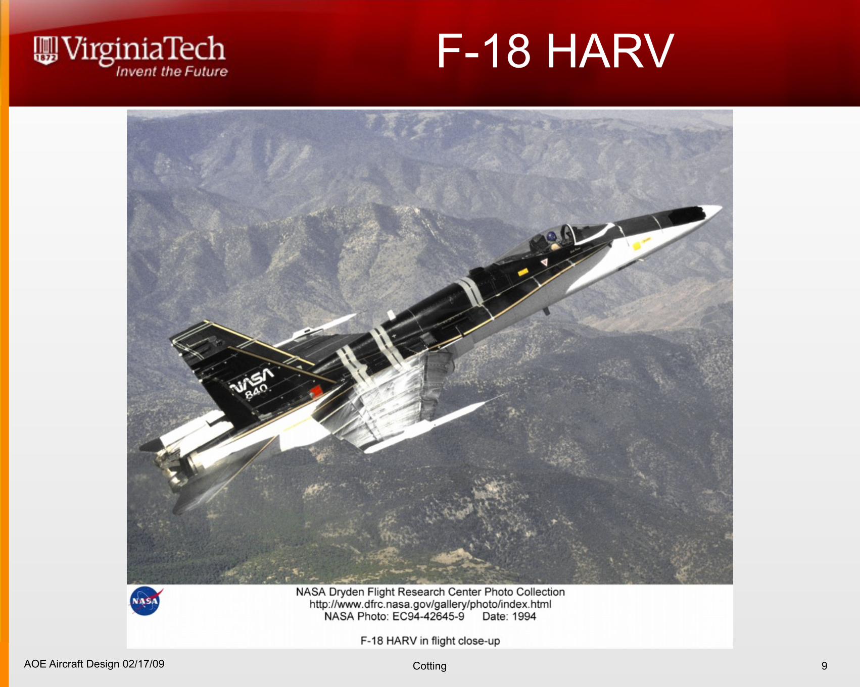
F-18 HARV
9
AOE Aircraft Design 02/17/09 Cotting
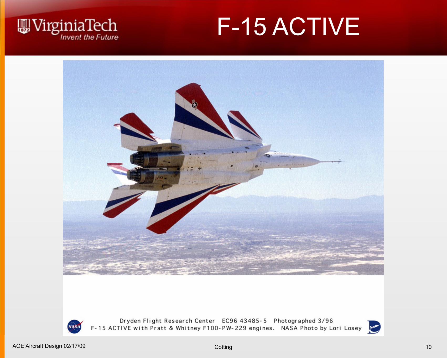
F-15 ACTIVE
10
AOE Aircraft Design 02/17/09 Cotting
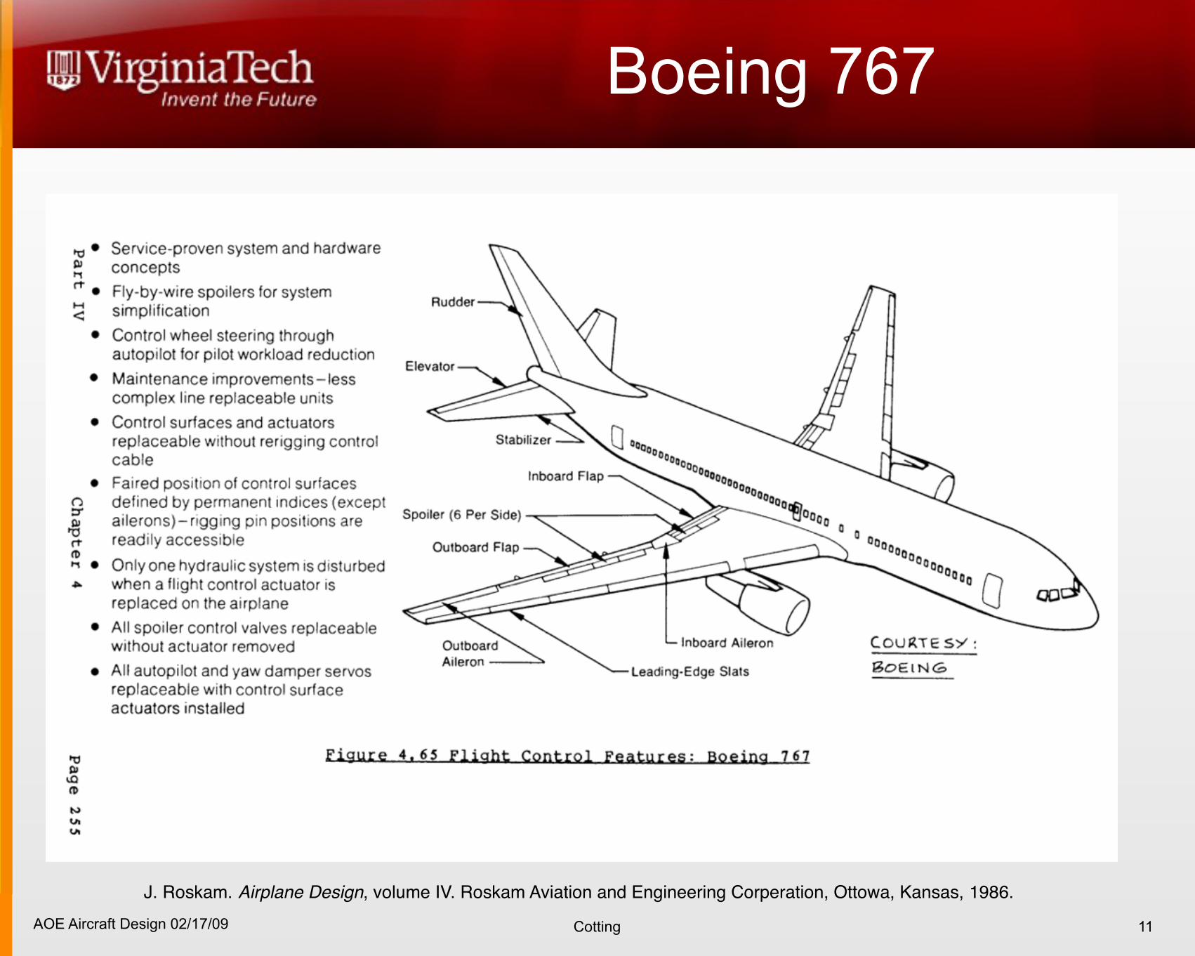
Boeing 767
11
J. Roskam. Airplane Design, volume IV. Roskam Aviation and Engineering Corperation, Ottowa, Kansas, 1986.
AOE Aircraft Design 02/17/09 Cotting
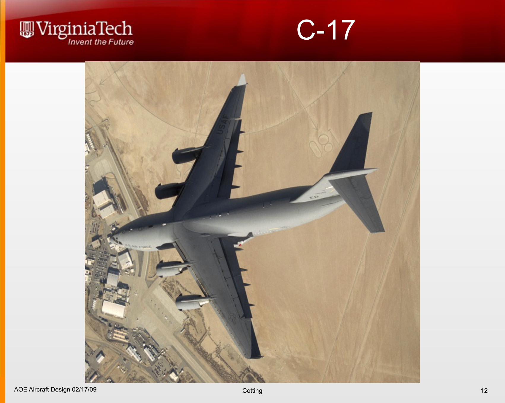
C-17
12
AOE Aircraft Design 02/17/09 Cotting
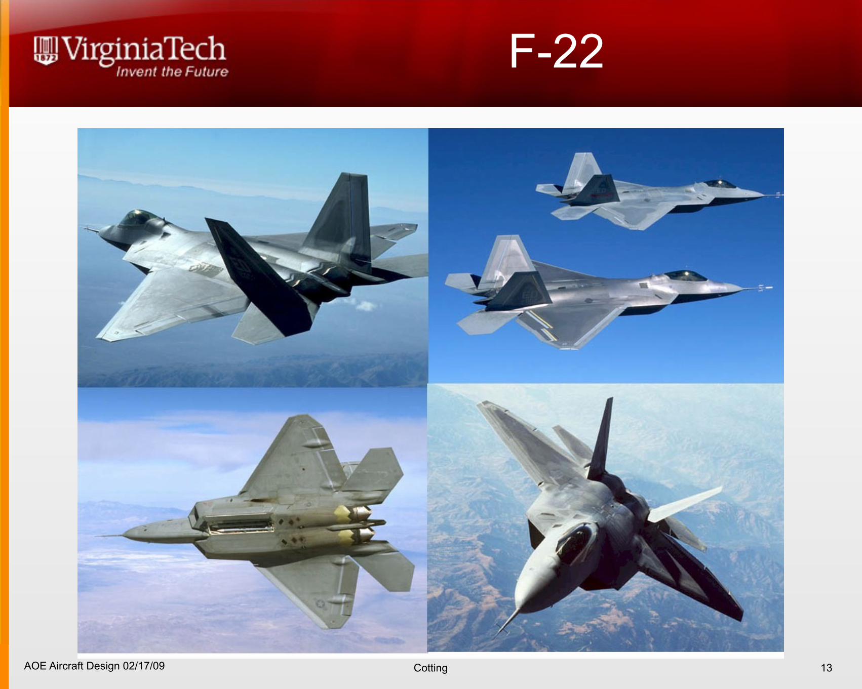
F-22
13
AOE Aircraft Design 02/17/09 Cotting
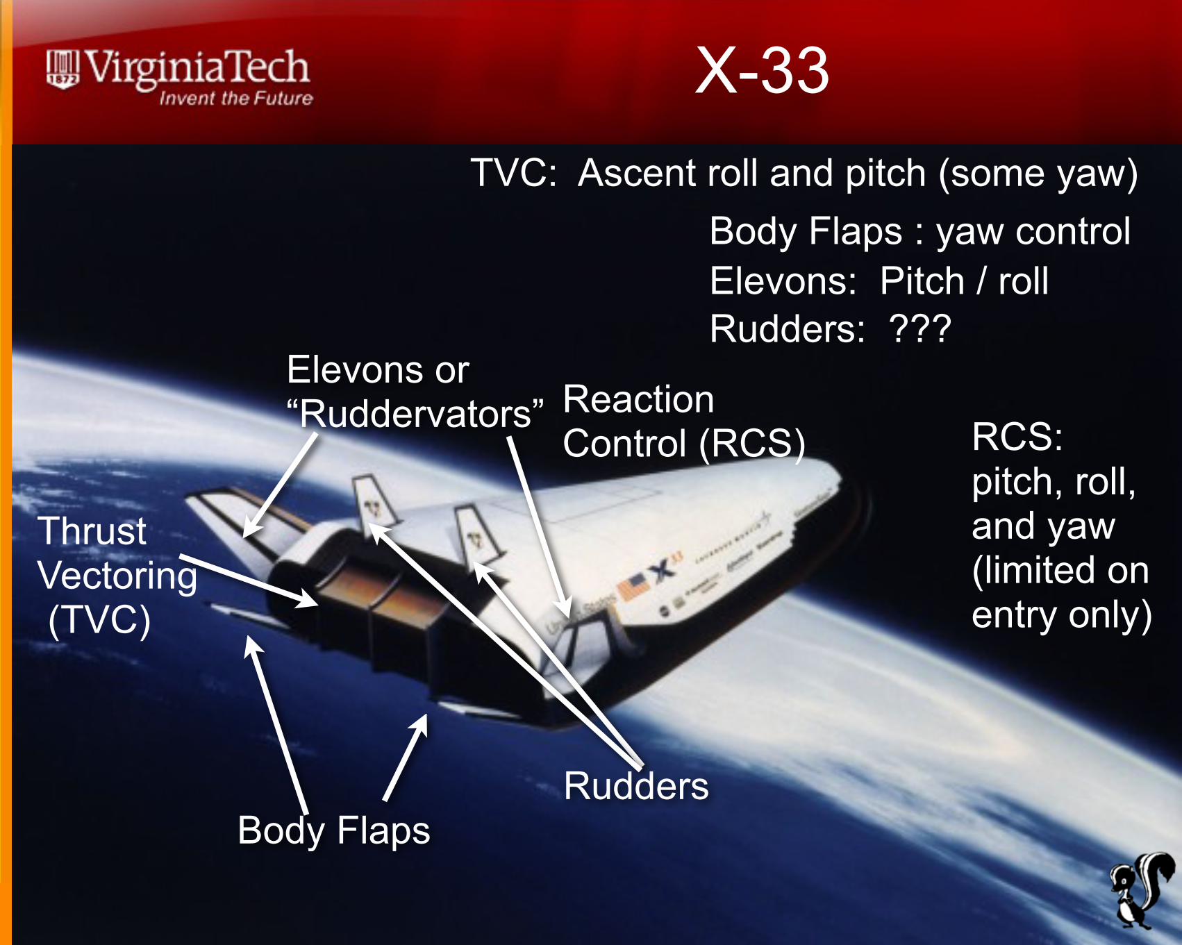
X-33
14
Body Flaps
Elevons or“Ruddervators”
Rudders
Thrust Vectoring (TVC)
Reaction Control (RCS)
TVC: Ascent roll and pitch (some yaw)Body Flaps : yaw controlElevons: Pitch / rollRudders: ???
RCS: pitch, roll, and yaw (limited on entry only)
AOE Aircraft Design 02/17/09 Cotting
X-35
15
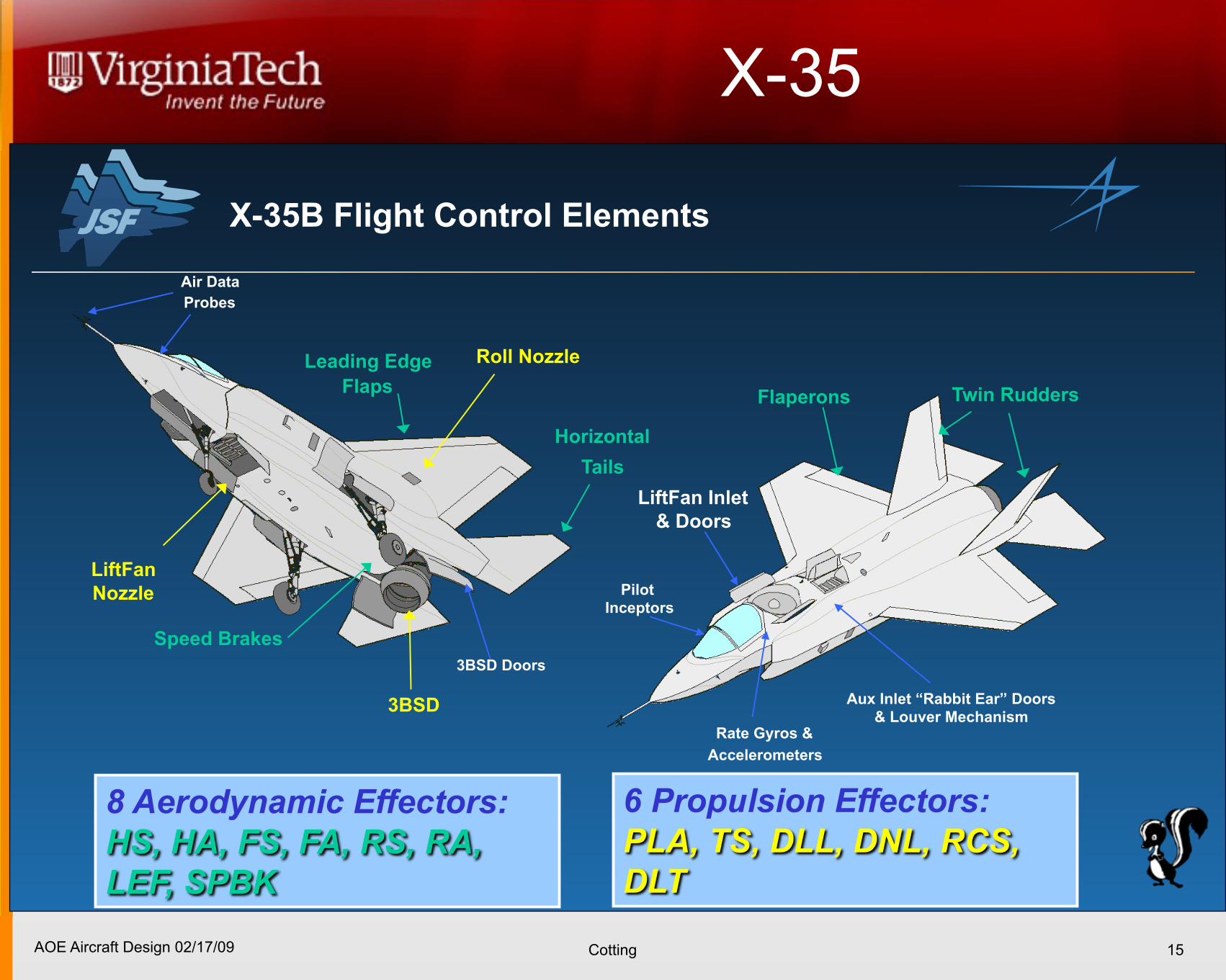
X-35B Flight Control Elements
3BSD Doors
LiftFan
Nozzle
Roll Nozzle!
Aux Inlet “Rabbit Ear” Doors
& Louver Mechanism
LiftFan Inlet
& Doors!
Flaperons
3BSD
Twin Rudders
Horizontal
Tails
Leading Edge
Flaps!
Air Data
Probes!
Rate Gyros &
Accelerometers
Pilot
Inceptors!
Speed Brakes!
AOE Aircraft Design 02/17/09 Cotting
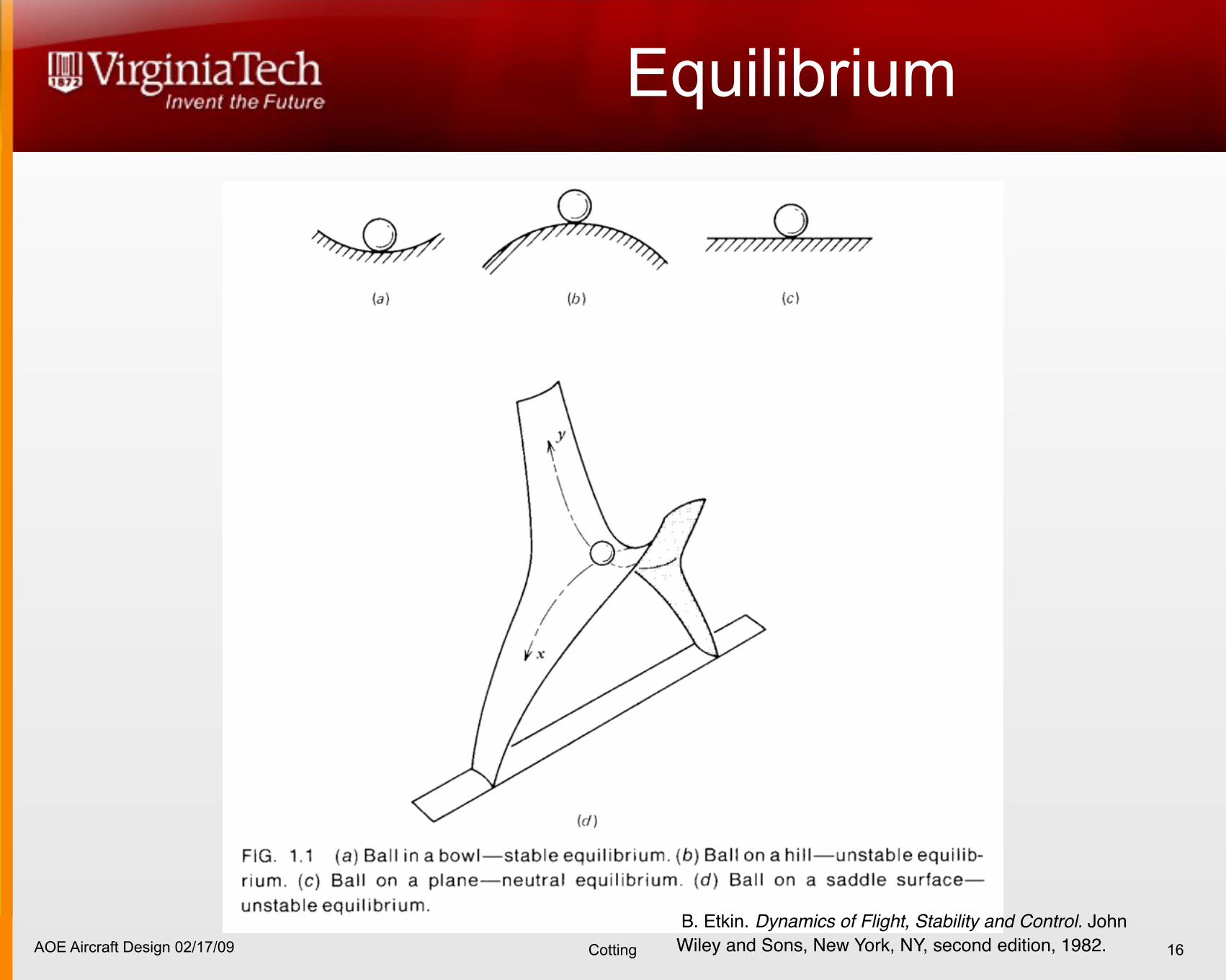
Equilibrium
16
B. Etkin. Dynamics of Flight, Stability and Control. John Wiley and Sons, New York, NY, second edition, 1982.
AOE Aircraft Design 02/17/09 Cotting
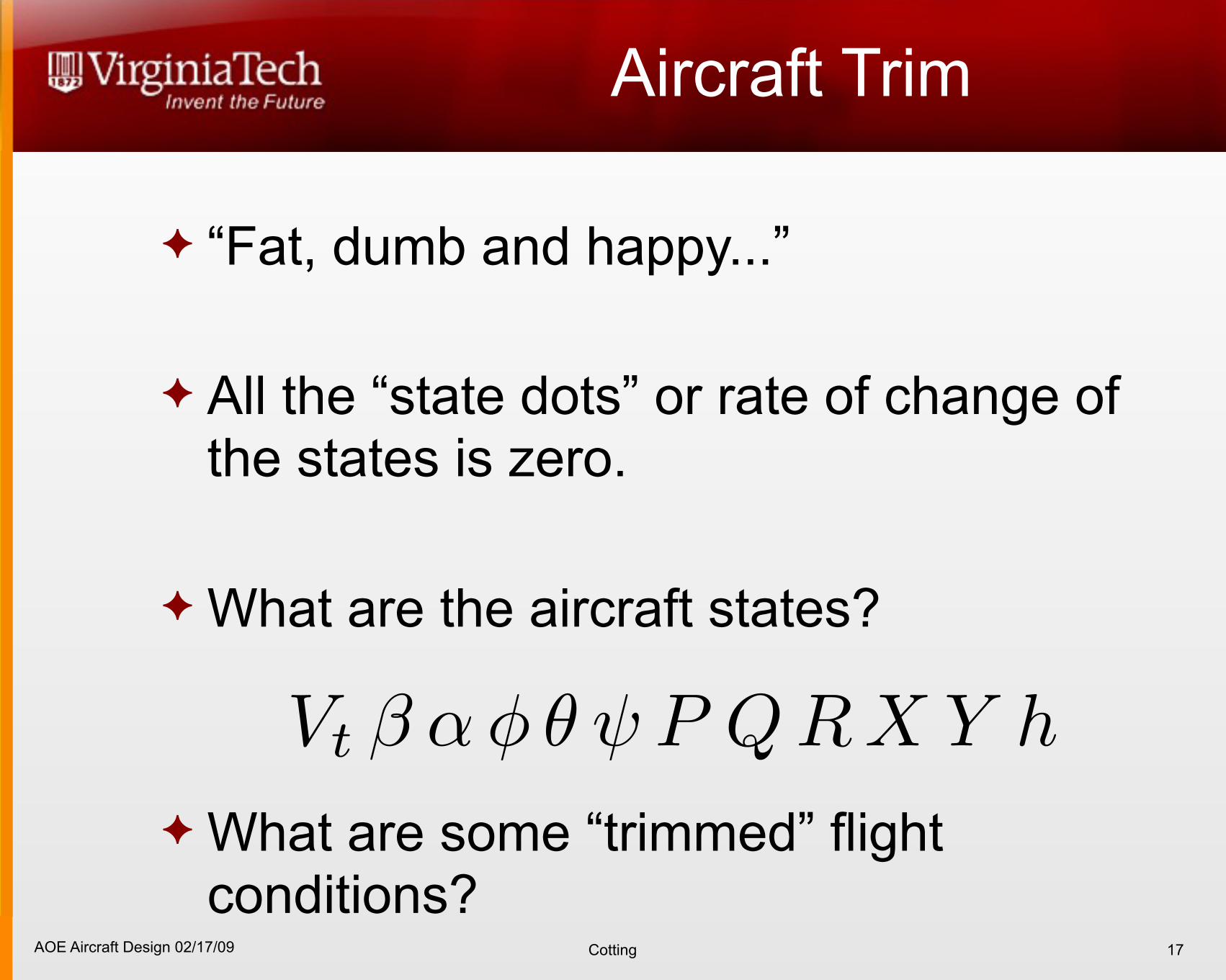
Aircraft Trim
“Fat, dumb and happy...”
All the “state dots” or rate of change of the states is zero.
What are the aircraft states?
What are some “trimmed” flight conditions?
17
AOE Aircraft Design 02/17/09 Cotting
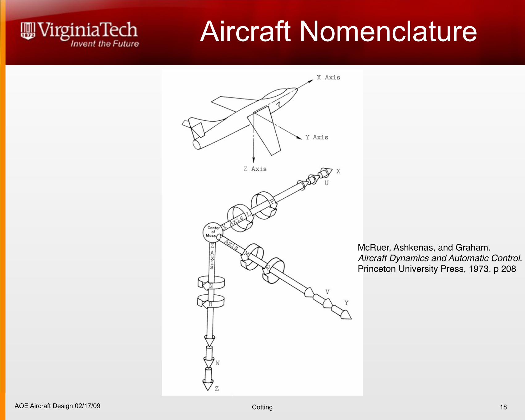
Aircraft Nomenclature
18
McRuer, Ashkenas, and Graham. Aircraft Dynamics and Automatic Control.Princeton University Press, 1973. p 208
AOE Aircraft Design 02/17/09 Cotting
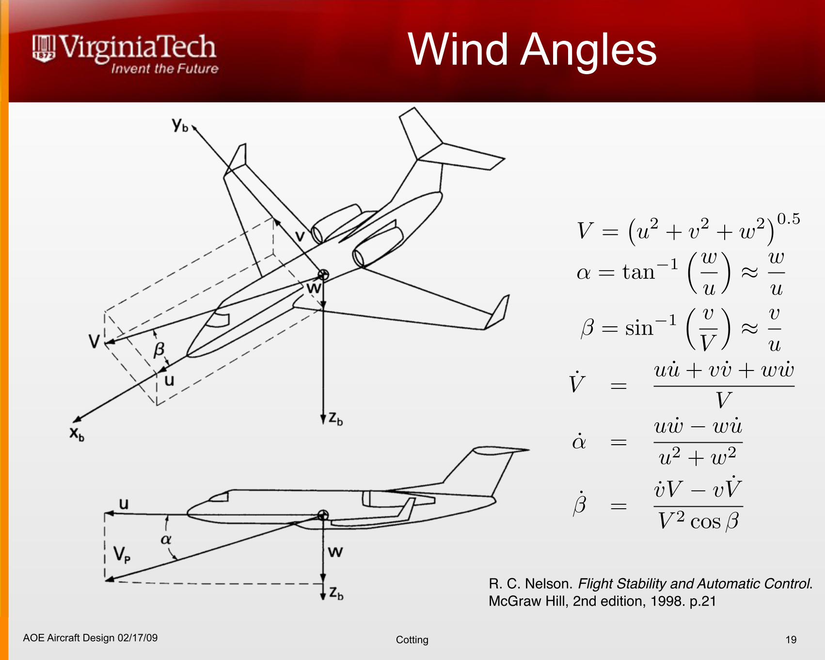
Wind Angles
19
R. C. Nelson. Flight Stability and Automatic Control. McGraw Hill, 2nd edition, 1998. p.21
V =!u2 + v2 + w2
"0.5
! = tan!1!w
u
"! w
u
! = sin!1! v
V
"! v
u
V =uu + vv + ww
V
! =uw ! wu
u2 + w2
" =vV ! vV
V 2 cos "
AOE Aircraft Design 02/17/09 Cotting
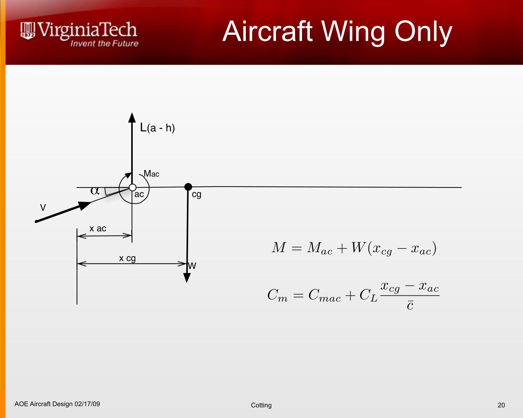
Aircraft Wing Only
20
ac cg
Mac
V
!
L(a - h)
x ac
Wx cg
AOE Aircraft Design 02/17/09 Cotting
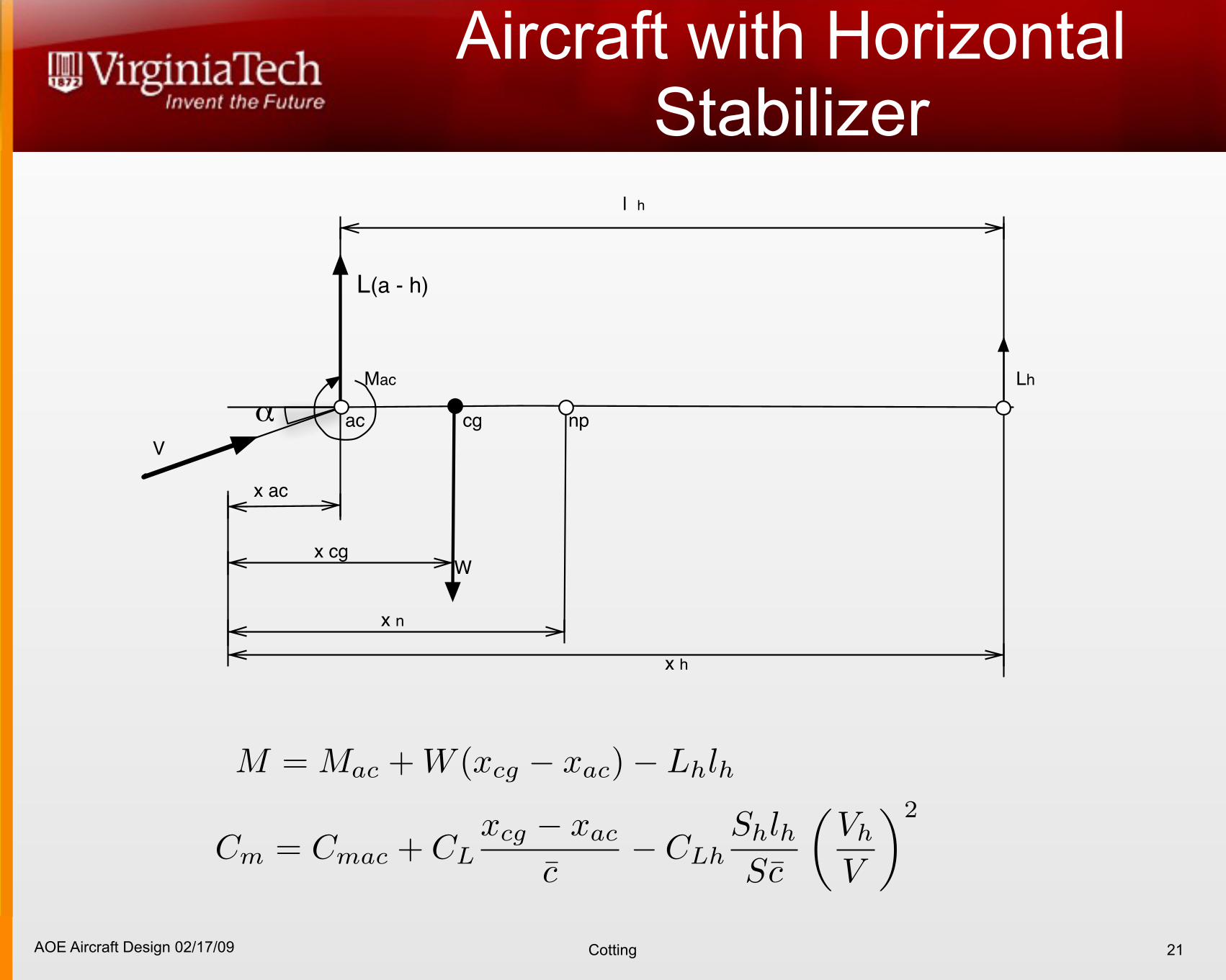
Aircraft with Horizontal Stabilizer
21
ac cg
Mac
V
!
L(a - h)
x ac
Wx cg
np
x n
Lh
x h
l h
AOE Aircraft Design 02/17/09 Cotting
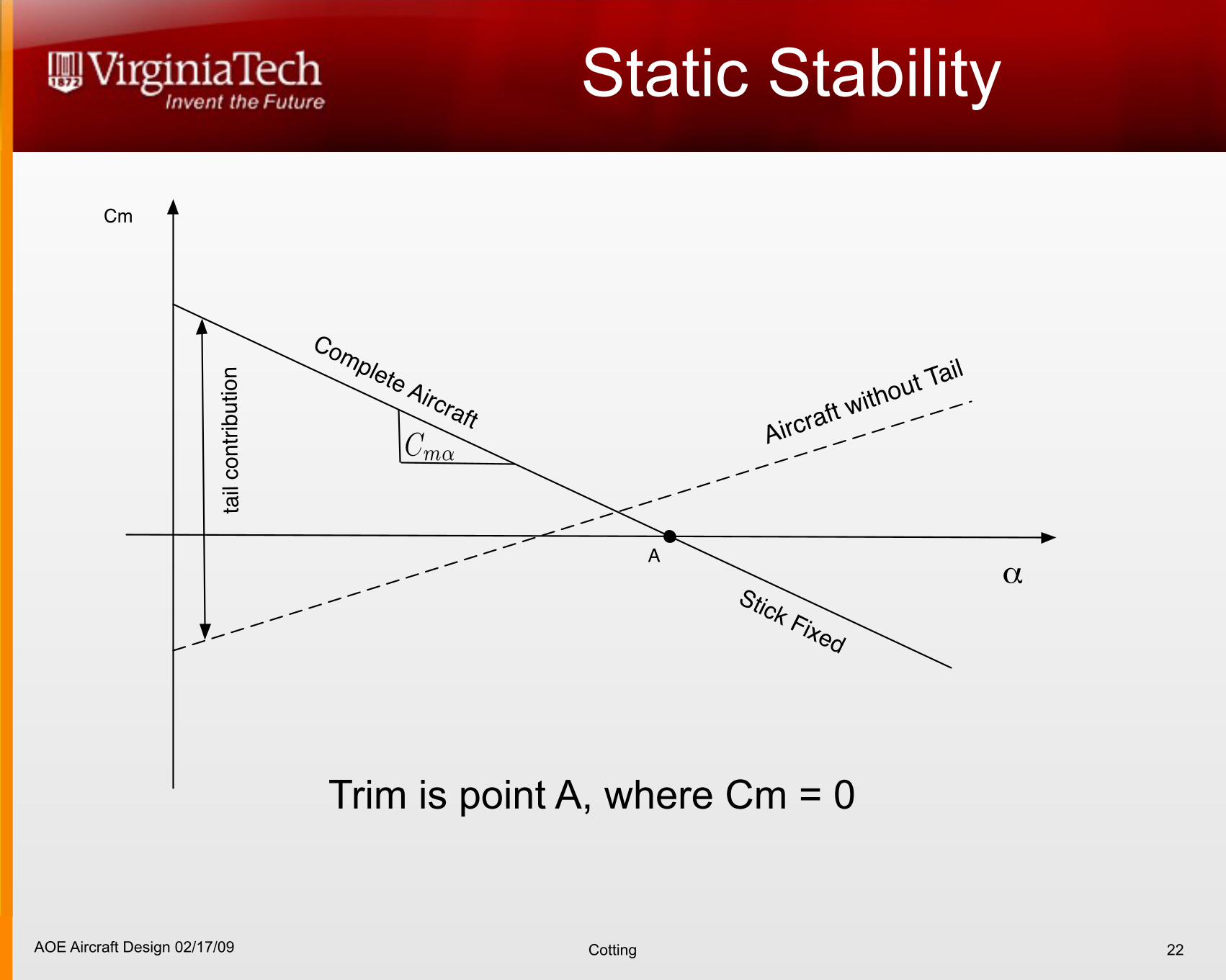
Static Stability
22
!
Cm
Complete AircraftAircraft w
ithout Tail
Stick Fixed
tail
contr
ibution
A
Trim is point A, where Cm = 0
AOE Aircraft Design 02/17/09 Cotting
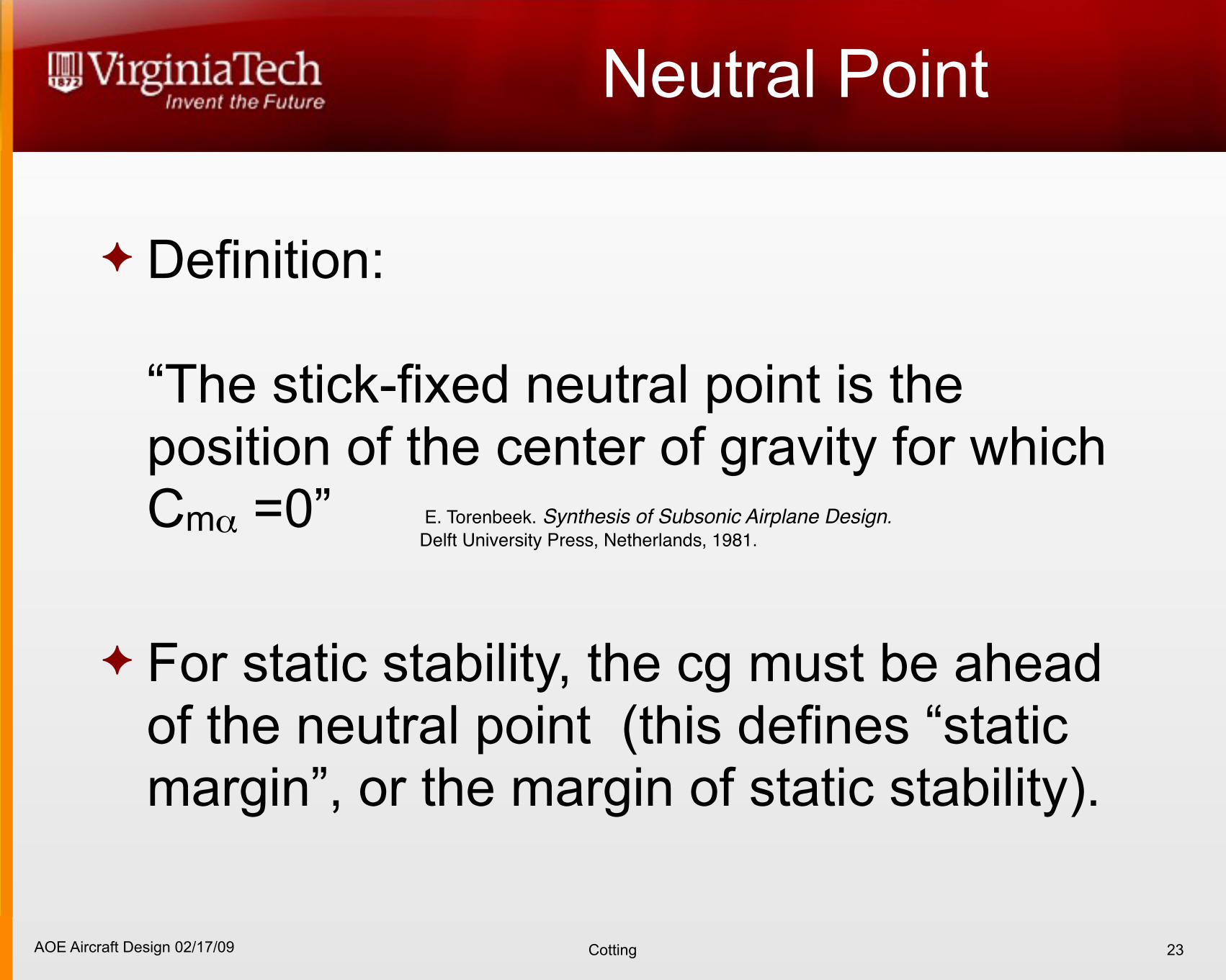
Neutral Point
Definition:
“The stick-fixed neutral point is the position of the center of gravity for which Cmα =0”
For static stability, the cg must be ahead of the neutral point (this defines “static margin”, or the margin of static stability).
23
E. Torenbeek. Synthesis of Subsonic Airplane Design. Delft University Press, Netherlands, 1981.
AOE Aircraft Design 02/17/09 Cotting
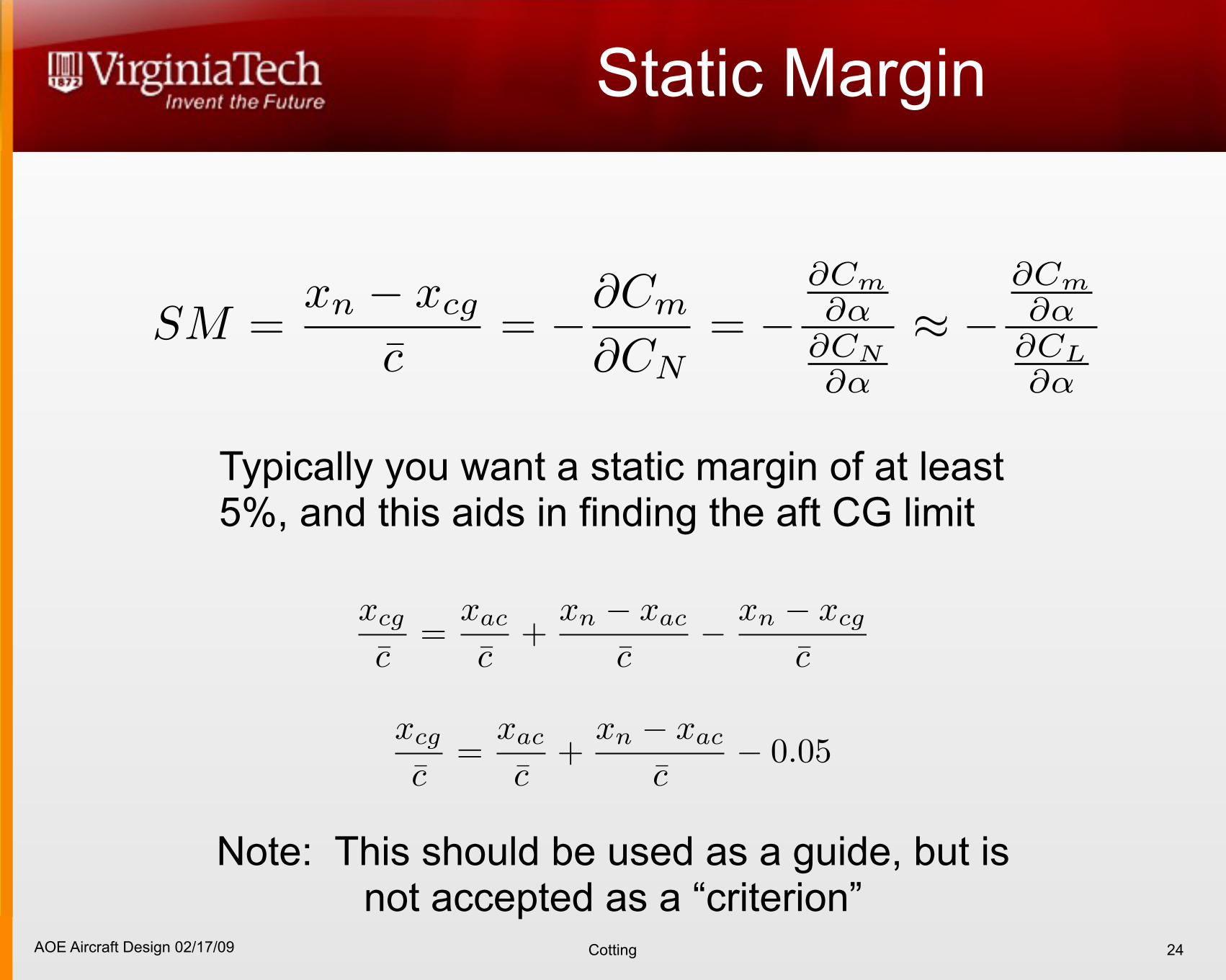
Static Margin
24
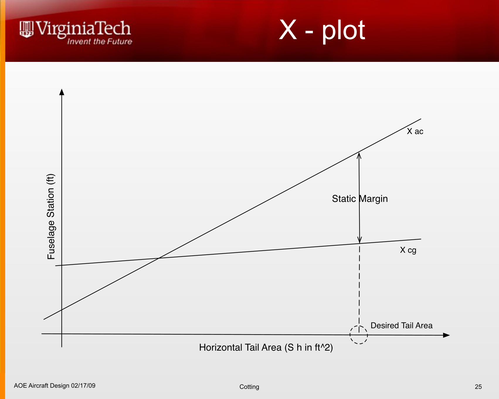
Typically you want a static margin of at least 5%, and this aids in finding the aft CG limit
Note: This should be used as a guide, but is not accepted as a “criterion”
AOE Aircraft Design 02/17/09 Cotting
X - plot
25
Horizontal Tail Area (S h in ft^2)
Fusela
ge S
tation (
ft)
X ac
X cg
Static Margin
Desired Tail Area
AOE Aircraft Design 02/17/09 Cotting
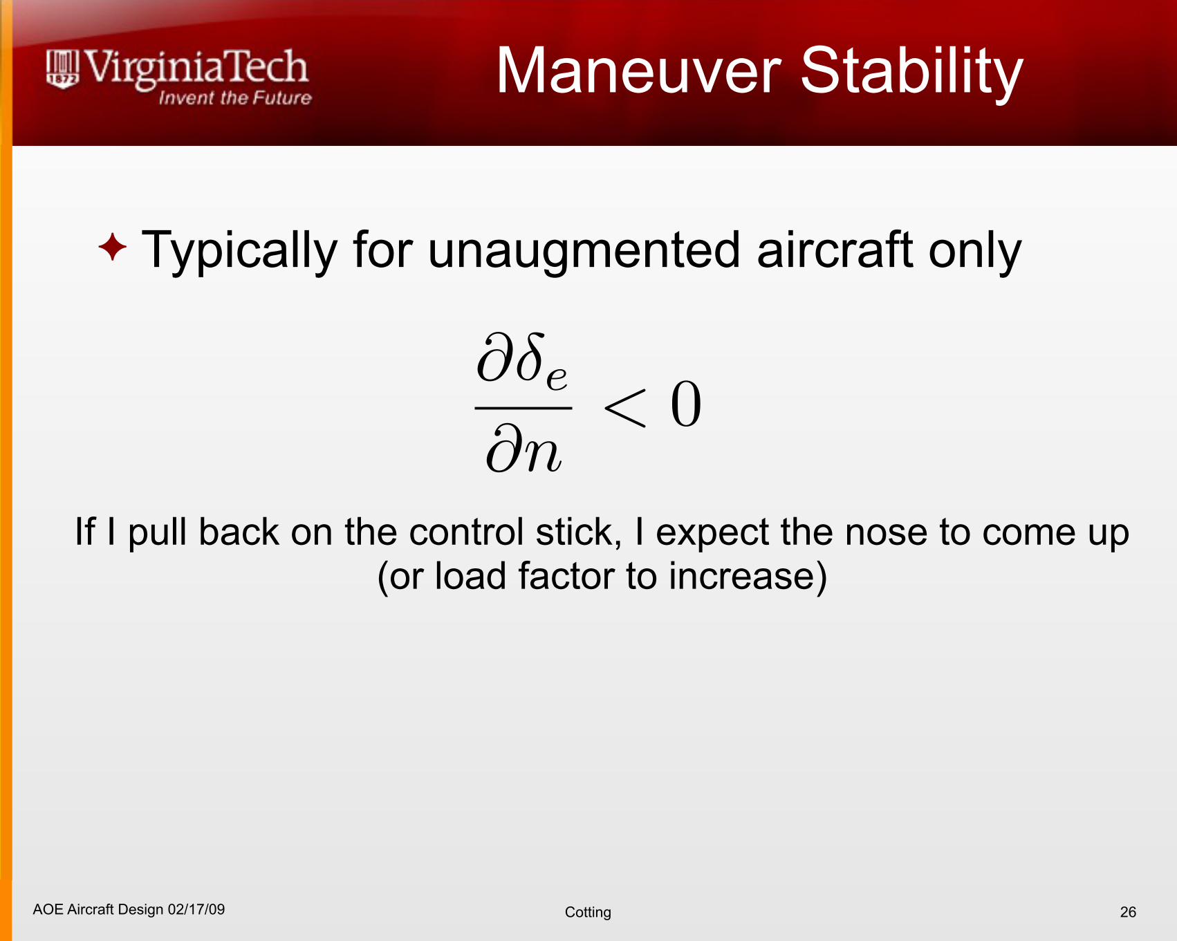
Maneuver Stability
Typically for unaugmented aircraft only
26
If I pull back on the control stick, I expect the nose to come up (or load factor to increase)
AOE Aircraft Design 02/17/09 Cotting
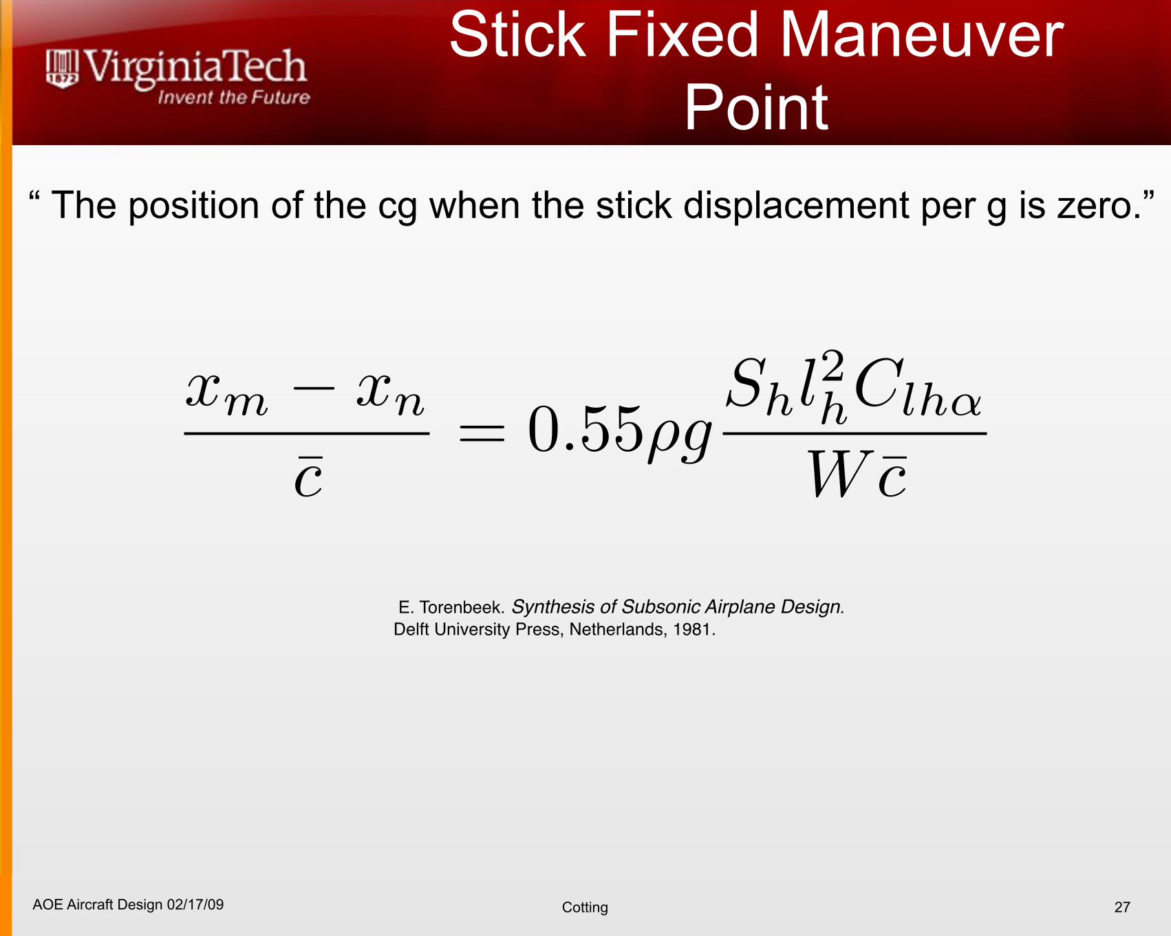
Stick Fixed Maneuver Point
27
“ The position of the cg when the stick displacement per g is zero.”
E. Torenbeek. Synthesis of Subsonic Airplane Design. Delft University Press, Netherlands, 1981.
AOE Aircraft Design 02/17/09 Cotting
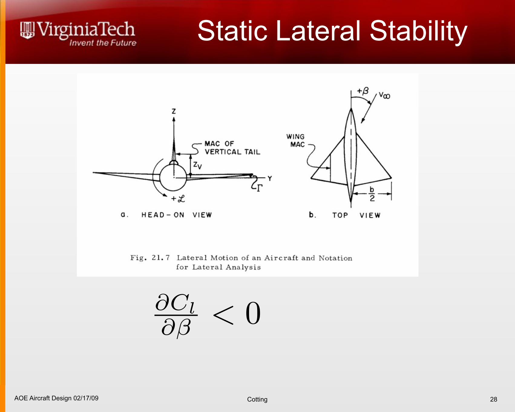
Static Lateral Stability
28
AOE Aircraft Design 02/17/09 Cotting
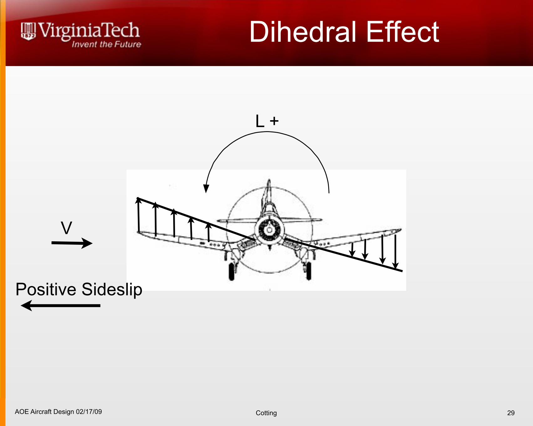
Dihedral Effect
29
L +
V
Positive Sideslip
AOE Aircraft Design 02/17/09 Cotting
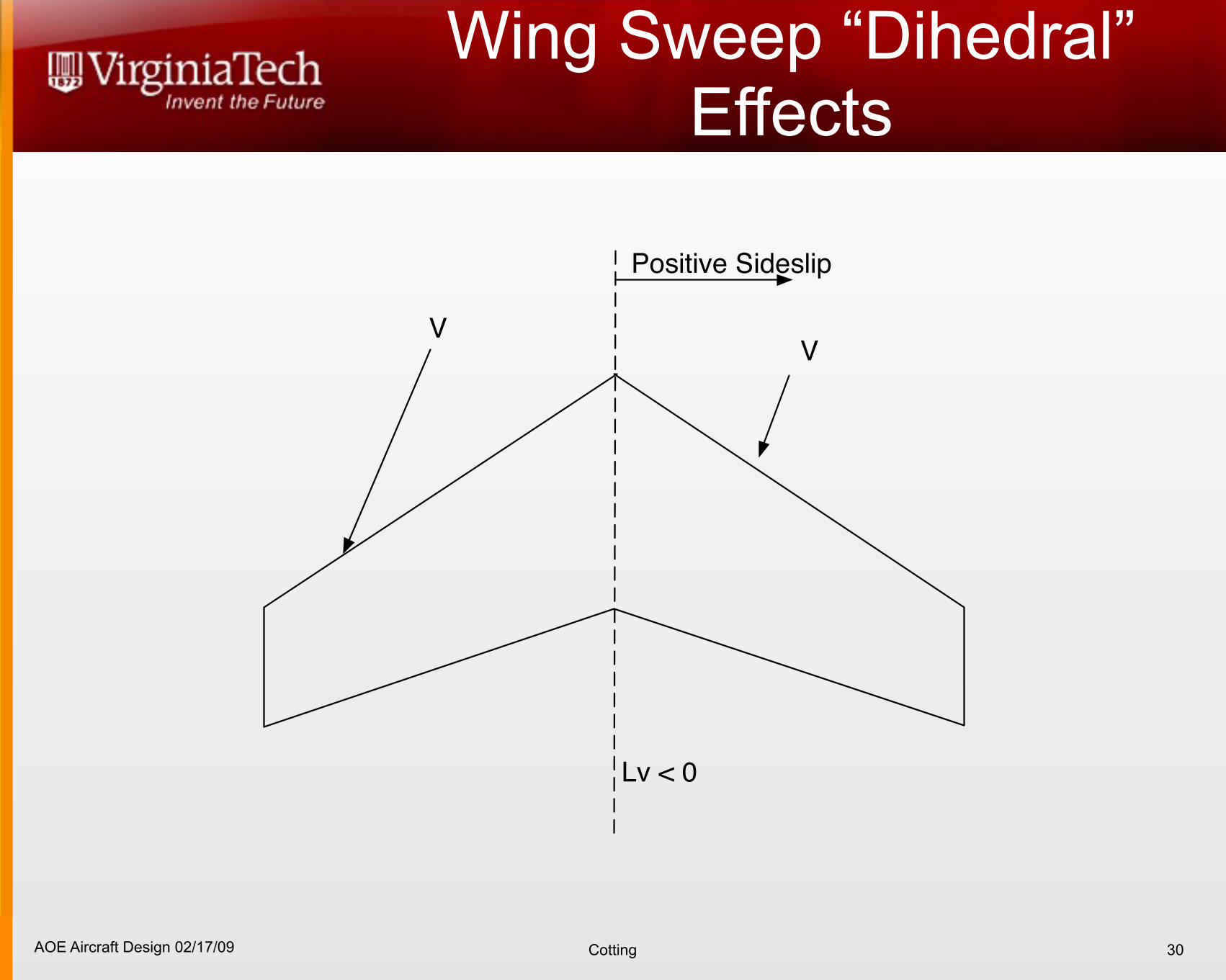
Wing Sweep “Dihedral” Effects
30
Positive Sideslip
Lv < 0
VV
AOE Aircraft Design 02/17/09 Cotting
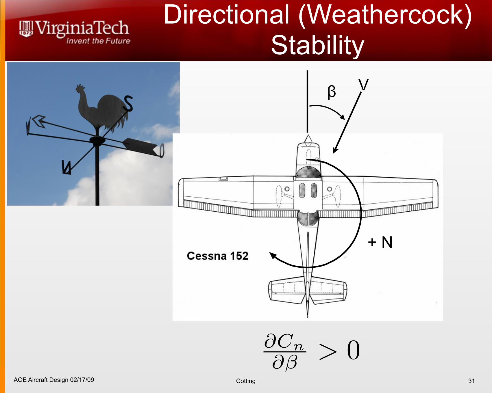
Directional (Weathercock) Stability
31
Vβ
+ N
AOE Aircraft Design 02/17/09 Cotting
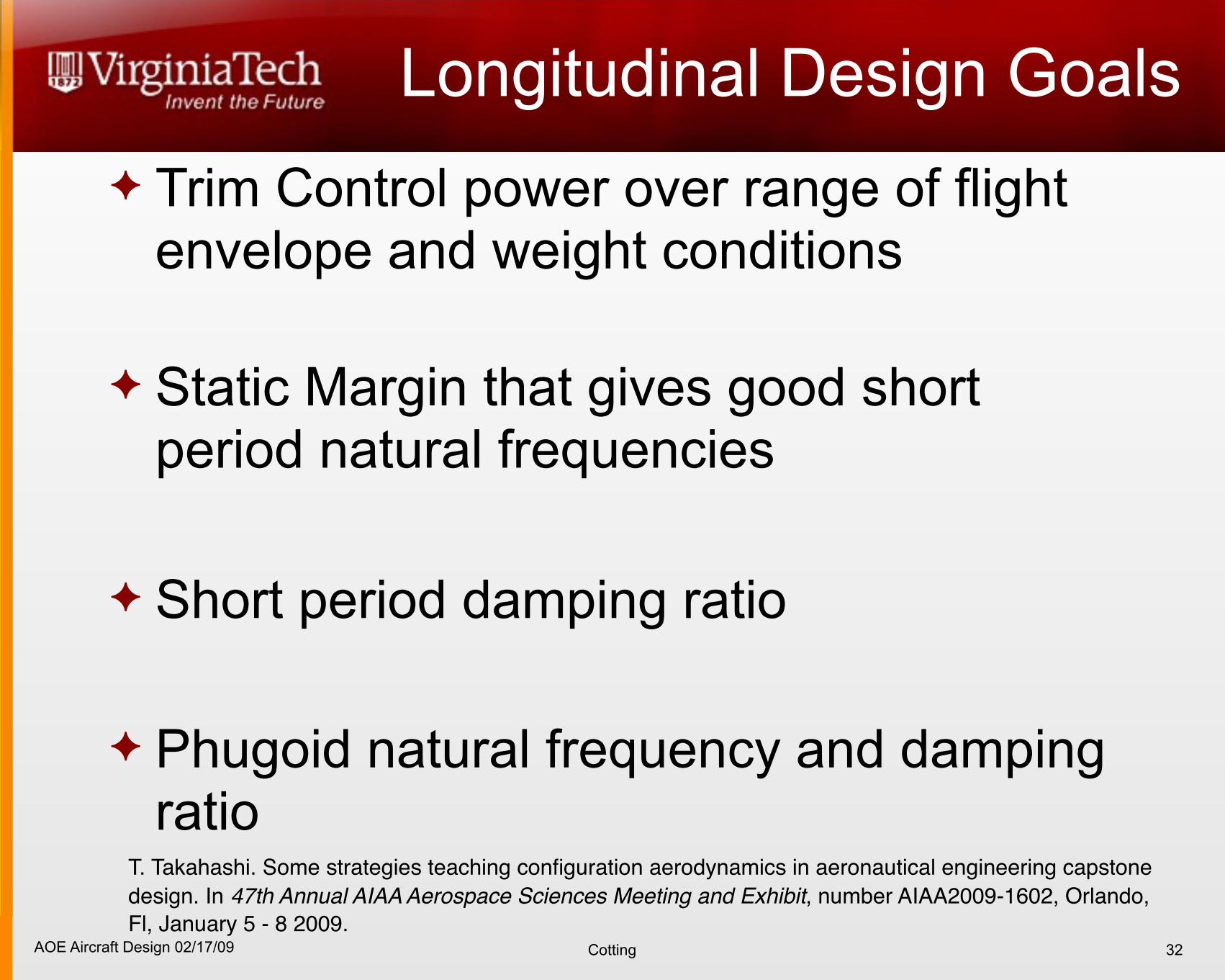
Longitudinal Design Goals Trim Control power over range of flight
envelope and weight conditions
Static Margin that gives good short period natural frequencies
Short period damping ratio
Phugoid natural frequency and damping ratio
32
T. Takahashi. Some strategies teaching configuration aerodynamics in aeronautical engineering capstone design. In 47th Annual AIAA Aerospace Sciences Meeting and Exhibit, number AIAA2009-1602, Orlando, Fl, January 5 - 8 2009.
AOE Aircraft Design 02/17/09 Cotting
Longitudinal
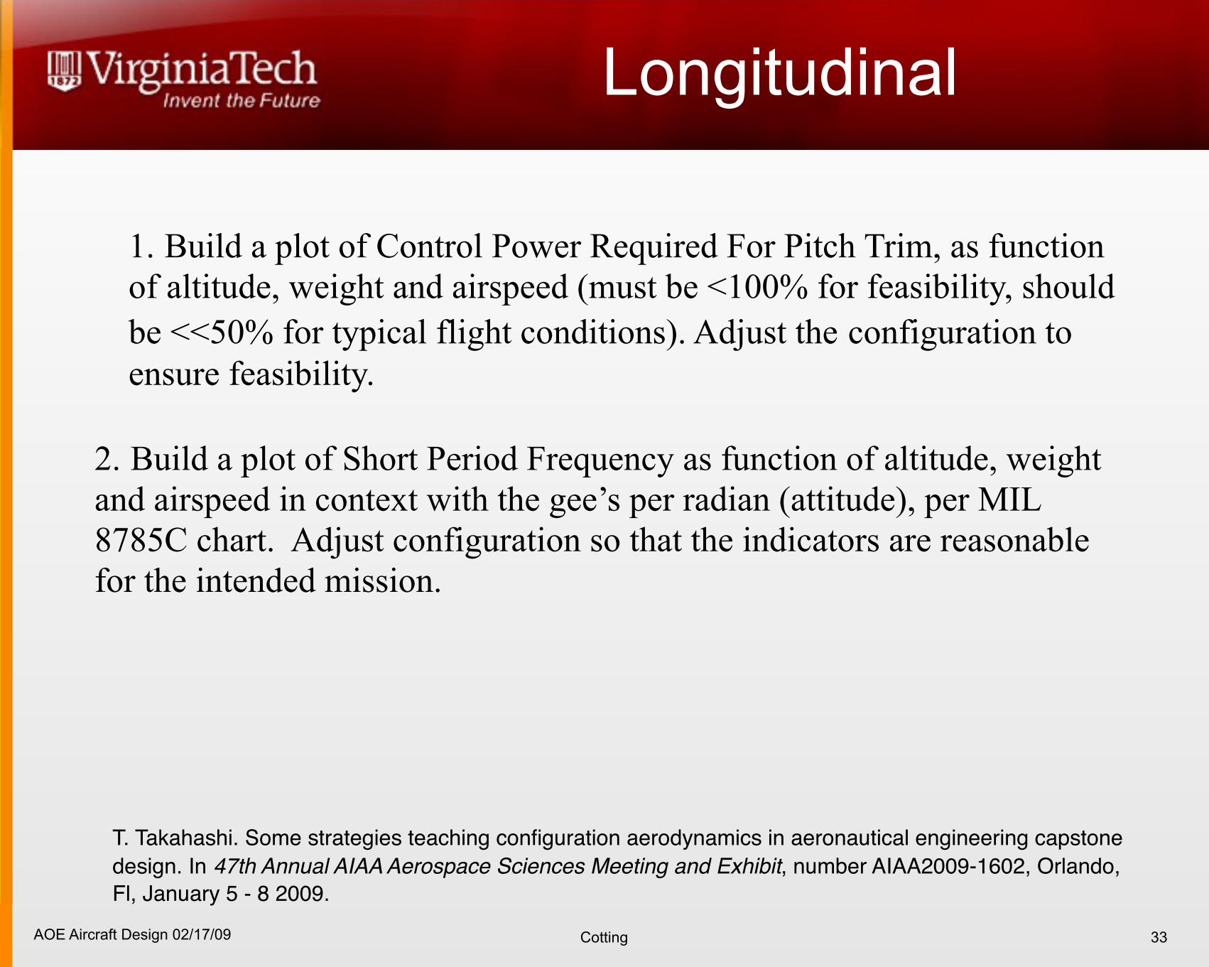
1. Build a plot of Control Power Required For Pitch Trim, as function of altitude, weight and airspeed (must be <100% for feasibility, should be <<50% for typical flight conditions). Adjust the configuration to ensure feasibility.
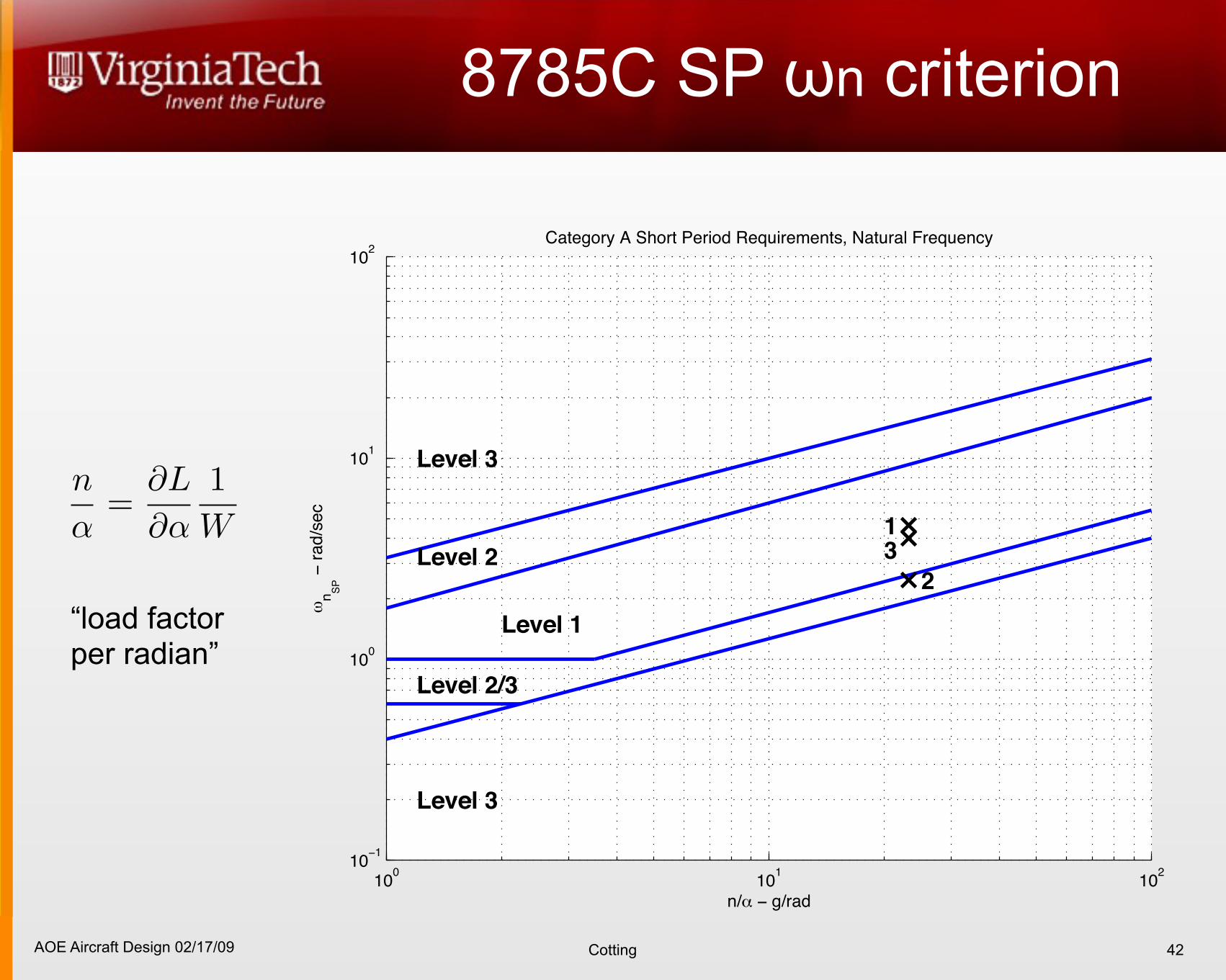
2. Build a plot of Short Period Frequency as function of altitude, weight and airspeed in context with the gee’s per radian (attitude), per MIL 8785C chart. Adjust configuration so that the indicators are reasonable for the intended mission.
33
T. Takahashi. Some strategies teaching configuration aerodynamics in aeronautical engineering capstone design. In 47th Annual AIAA Aerospace Sciences Meeting and Exhibit, number AIAA2009-1602, Orlando, Fl, January 5 - 8 2009.
AOE Aircraft Design 02/17/09 Cotting
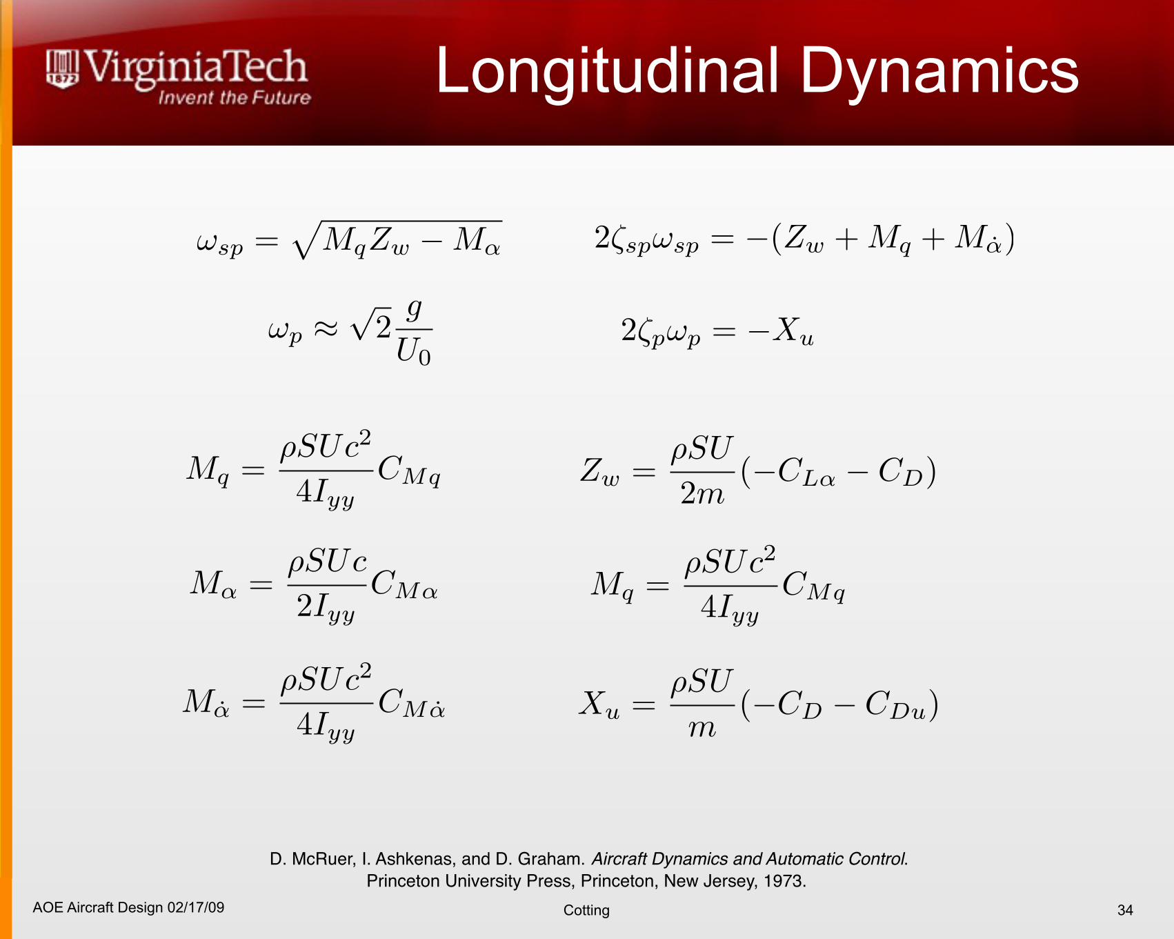
Longitudinal Dynamics
34
D. McRuer, I. Ashkenas, and D. Graham. Aircraft Dynamics and Automatic Control. Princeton University Press, Princeton, New Jersey, 1973.

AOE Aircraft Design 02/17/09 Cotting
Time to Half / Double
35
C. A. Woolsey, Review of Linear, Time-Invariant Ordinary Differential Equations, accessed 02/17/09,http://www.aoe.vt.edu/~cwoolsey/Courses/AOE3134/Supplemental/LTIODEs.pdf
AOE Aircraft Design 02/17/09 Cotting
8785C Aircraft Classes
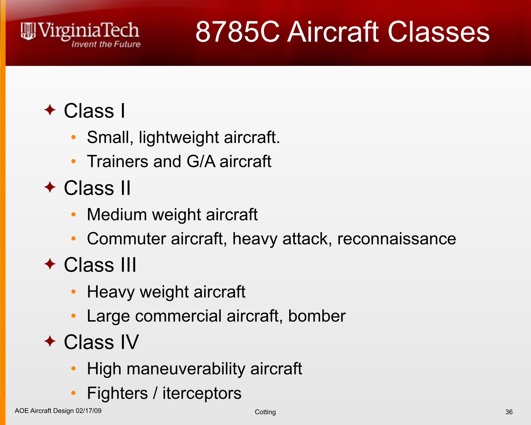
Class I• Small, lightweight aircraft.• Trainers and G/A aircraft
Class II • Medium weight aircraft• Commuter aircraft, heavy attack, reconnaissance
Class III• Heavy weight aircraft• Large commercial aircraft, bomber
Class IV• High maneuverability aircraft• Fighters / iterceptors
36
AOE Aircraft Design 02/17/09 Cotting
8785C Flight Categories
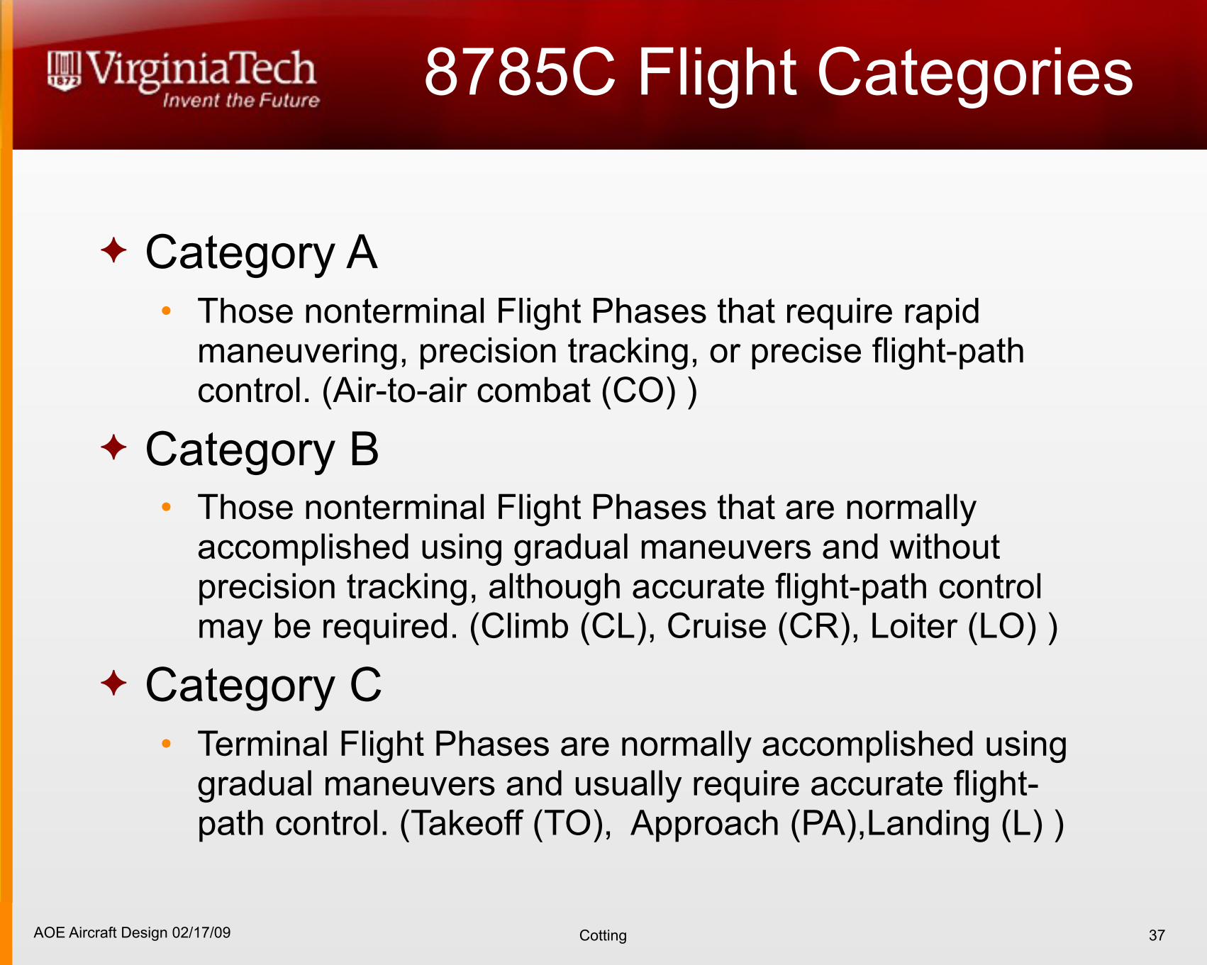
Category A• Those nonterminal Flight Phases that require rapid
maneuvering, precision tracking, or precise flight-path control. (Air-to-air combat (CO) )
Category B• Those nonterminal Flight Phases that are normally
accomplished using gradual maneuvers and without precision tracking, although accurate flight-path control may be required. (Climb (CL), Cruise (CR), Loiter (LO) )
Category C• Terminal Flight Phases are normally accomplished using
gradual maneuvers and usually require accurate flight-path control. (Takeoff (TO), Approach (PA),Landing (L) )
37
AOE Aircraft Design 02/17/09 Cotting
PIO
38
AOE Aircraft Design 02/17/09 Cotting
PIO
39
AOE Aircraft Design 02/17/09 Cotting
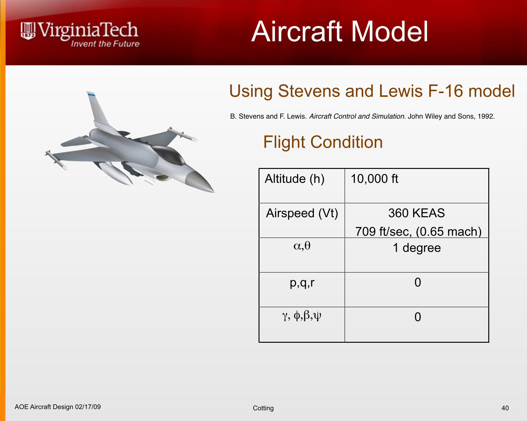
Aircraft Model
40
Using Stevens and Lewis F-16 model B. Stevens and F. Lewis. Aircraft Control and Simulation. John Wiley and Sons, 1992.
Altitude (h) 10,000 ft
Airspeed (Vt) 360 KEAS 709 ft/sec, (0.65 mach)
α,θ 1 degree
p,q,r 0
γ, φ,β,ψ 0
Flight Condition
AOE Aircraft Design 02/17/09 Cotting
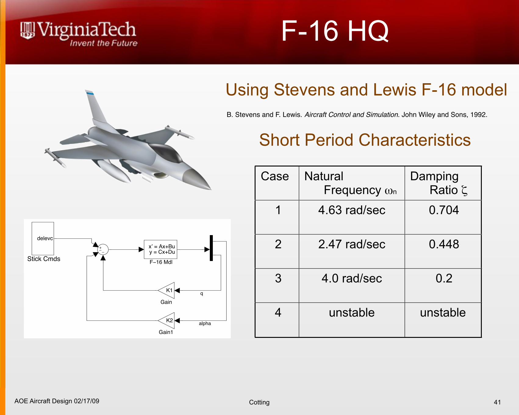
F-16 HQ
41
Using Stevens and Lewis F-16 model B. Stevens and F. Lewis. Aircraft Control and Simulation. John Wiley and Sons, 1992.
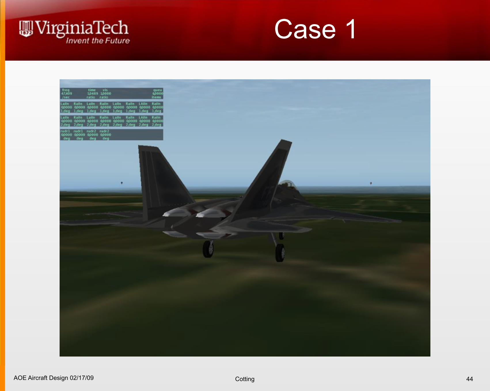
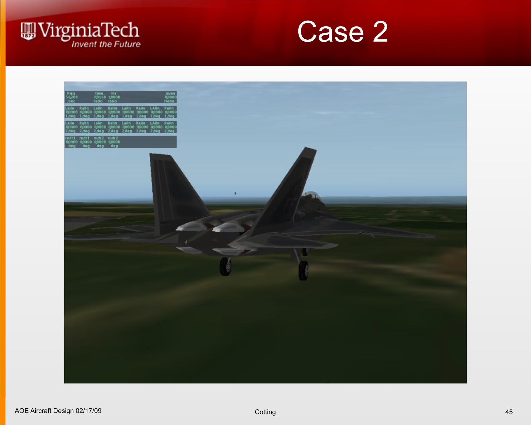
Case Natural Frequency ωn
Damping Ratio ζ
1 4.63 rad/sec 0.704
2 2.47 rad/sec 0.448
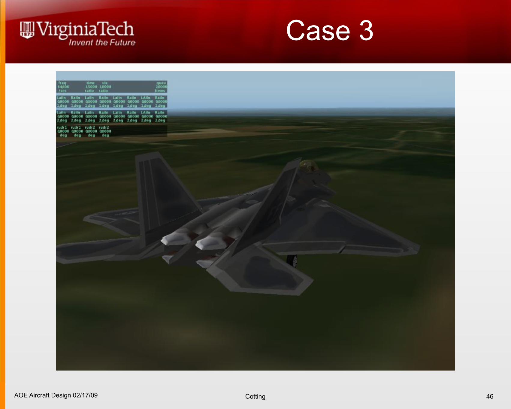
3 4.0 rad/sec 0.2
4 unstable unstable
Short Period Characteristics
Stick Cmds
delevc
Gain1
K2
Gain
K1
F!16 Mdl
x’ = Ax+Bu y = Cx+Du
q
alpha
AOE Aircraft Design 02/17/09 Cotting
8785C SP ωn criterion
42
100 101 10210−1
100
101
102
ωn SP
− ra
d/se
c
n/α − g/rad
Category A Short Period Requirements, Natural Frequency
Level 1
Level 2/3
Level 2
Level 3
Level 3
1
23
n
!=
"L
"!
1W
“load factorper radian”
AOE Aircraft Design 02/17/09 Cotting
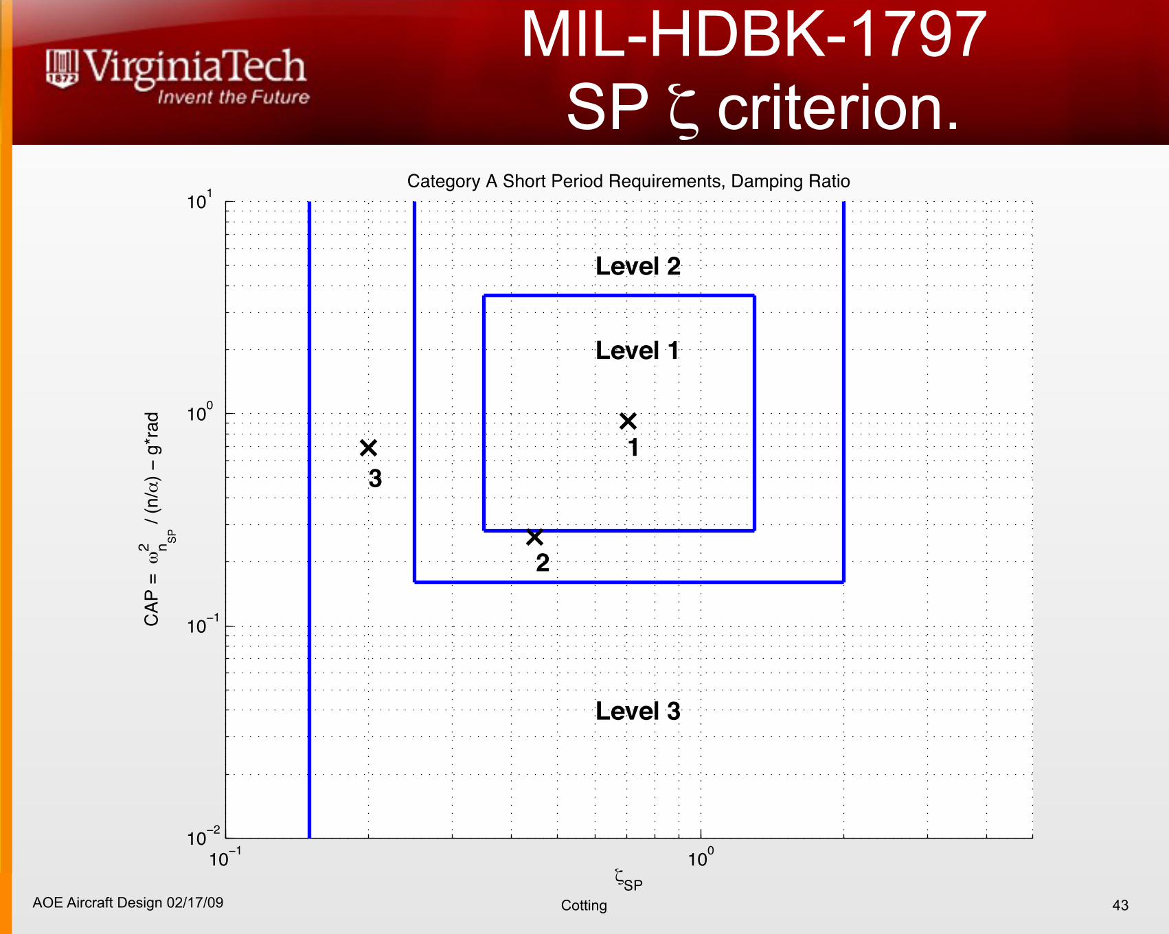
MIL-HDBK-1797 SP ζ criterion.
43
10−1 10010−2
10−1
100
101
ζSP
CAP
= ω
2 n SP /
(n/α
) − g
*rad
Category A Short Period Requirements, Damping Ratio
Level 1
Level 2
Level 3
1
2
3
AOE Aircraft Design 02/17/09 Cotting
Case 1
44
AOE Aircraft Design 02/17/09 Cotting
Case 2
45
AOE Aircraft Design 02/17/09 Cotting
Case 3
46
AOE Aircraft Design 02/17/09 Cotting
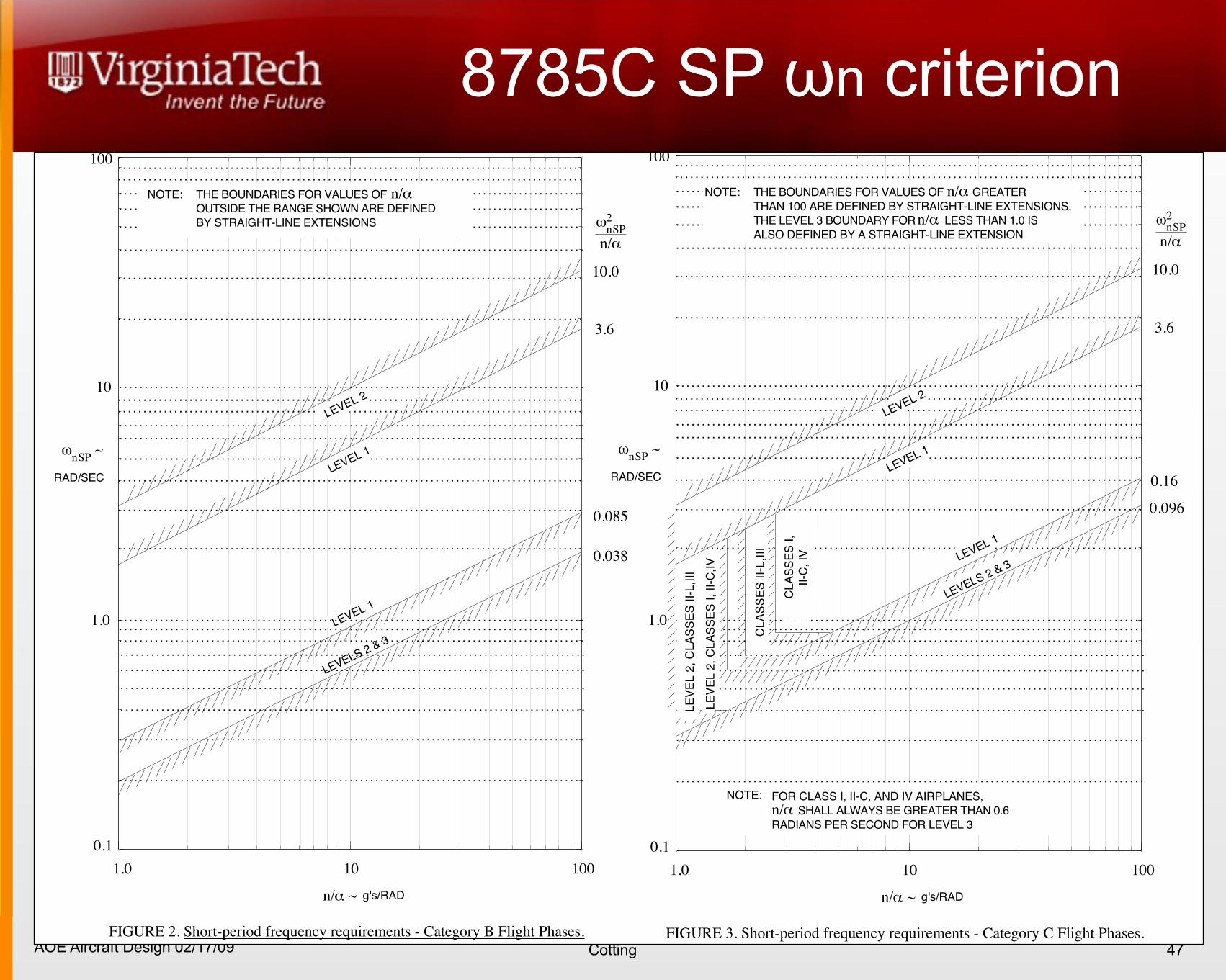
8785C SP ωn criterion
47
MIL-F-8785C
15
100
10
1.0
0.1
1.0 10 100
NOTE: THE BOUNDARIES FOR VALUES OF
OUTSIDE THE RANGE SHOWN ARE DEFINED
BY STRAIGHT-LINE EXTENSIONS
10.0
3.6
0.085
0.038
n/!
"nSP
~
RAD/SEC
n/! ~ g's/RAD
LEVEL 1
LEVEL 2
LEVELS 2 & 3
LEVEL 1
"nSP2
n/!
FIGURE 2. Short-period frequency requirements - Category B Flight Phases.
MIL-F-8785C
16
100
10
1.0
0.1
1.0 10 100
NOTE: THE BOUNDARIES FOR VALUES OF GREATER
THAN 100 ARE DEFINED BY STRAIGHT-LINE EXTENSIONS.
THE LEVEL 3 BOUNDARY FOR LESS THAN 1.0 IS
ALSO DEFINED BY A STRAIGHT-LINE EXTENSION
10.0
3.6
0.16
0.096
n/!
"nSP
~
RAD/SEC
n/! ~ g's/RAD
LEVEL 1
LEVEL 2
LEVELS 2 & 3LEVEL 1
"nSP2
n/!
n/!
NOTE: FOR CLASS I, II-C, AND IV AIRPLANES,
SHALL ALWAYS BE GREATER THAN 0.6
RADIANS PER SECOND FOR LEVEL 3
n/!
LE
VE
L 2
, C
LA
SS
ES
II-
L,I
II
LE
VE
L 2
, C
LA
SS
ES
I,
II-C
,IV
CL
AS
SE
S I
I-L
,III
CL
AS
SE
S I
,
II-C
, IV
FIGURE 3. Short-period frequency requirements - Category C Flight Phases.
AOE Aircraft Design 02/17/09 Cotting
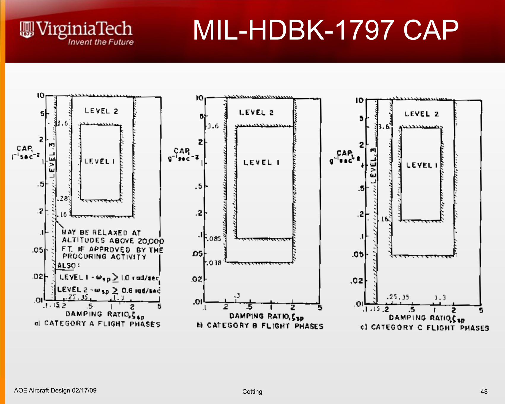
MIL-HDBK-1797 CAP
48
MIL
–S
TD
–1
79
7A
AP
PE
ND
IX A
174
AOE Aircraft Design 02/17/09 Cotting
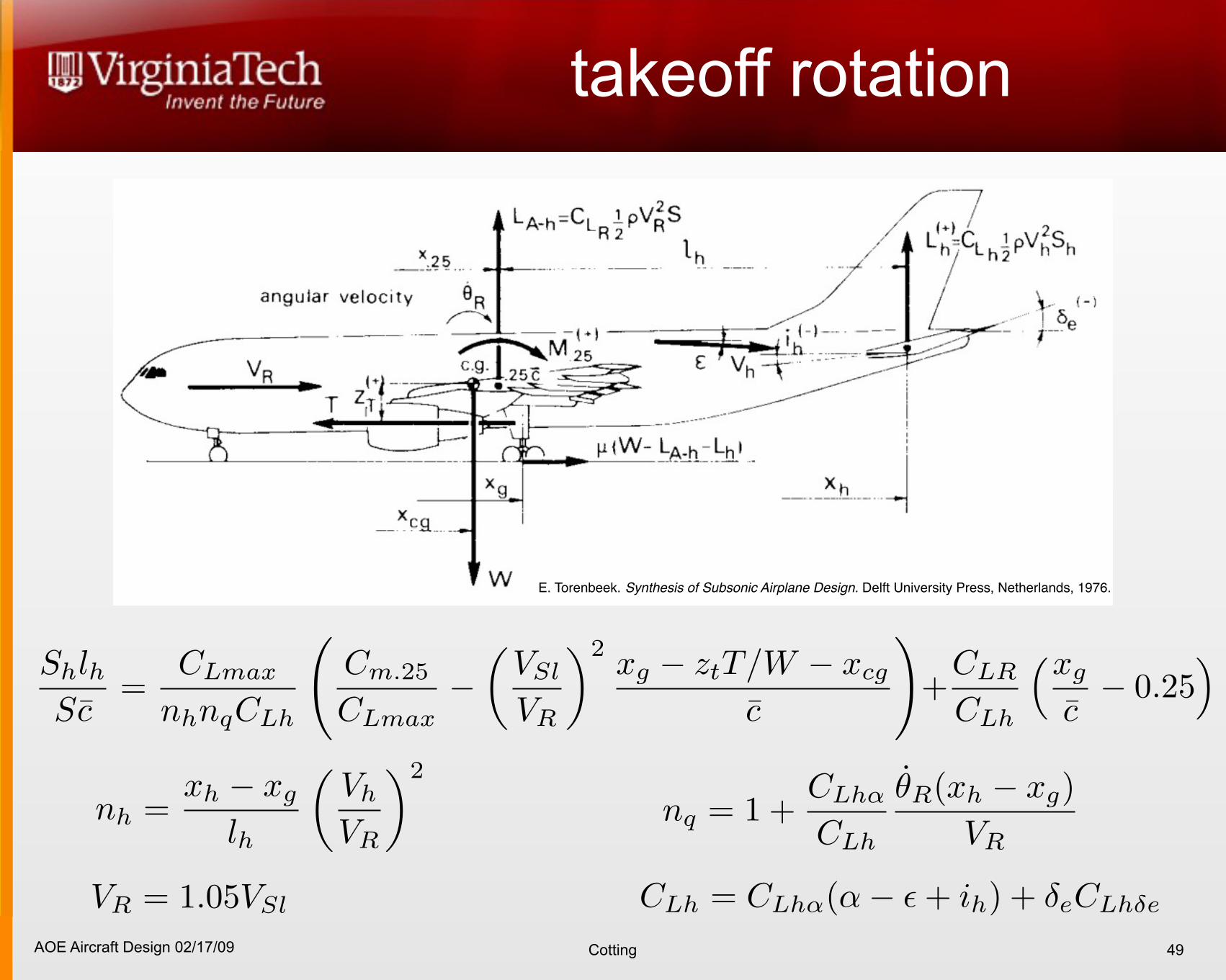
takeoff rotation
49
E. Torenbeek. Synthesis of Subsonic Airplane Design. Delft University Press, Netherlands, 1976.
AOE Aircraft Design 02/17/09 Cotting
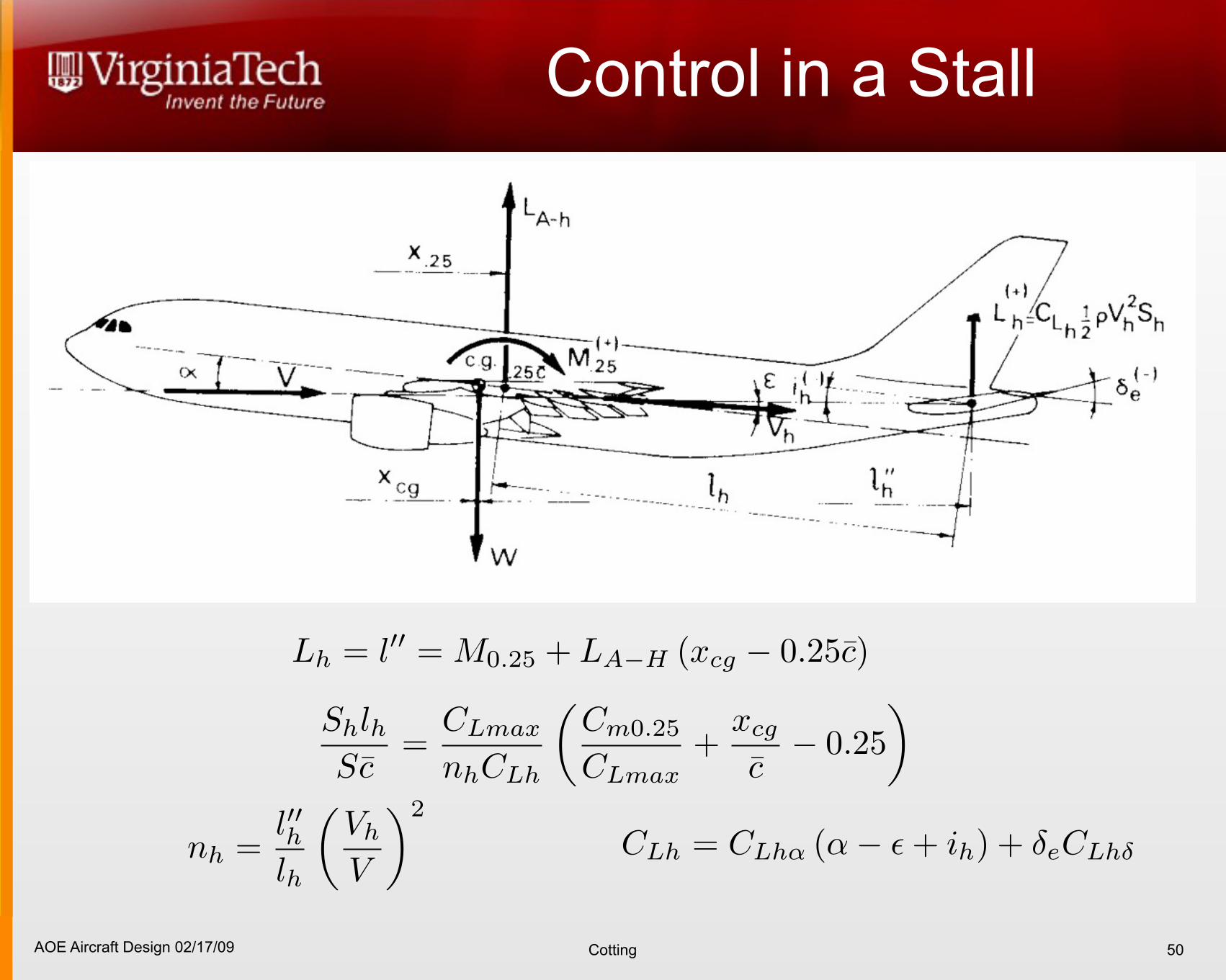
Control in a Stall
50
AOE Aircraft Design 02/17/09 Cotting 51
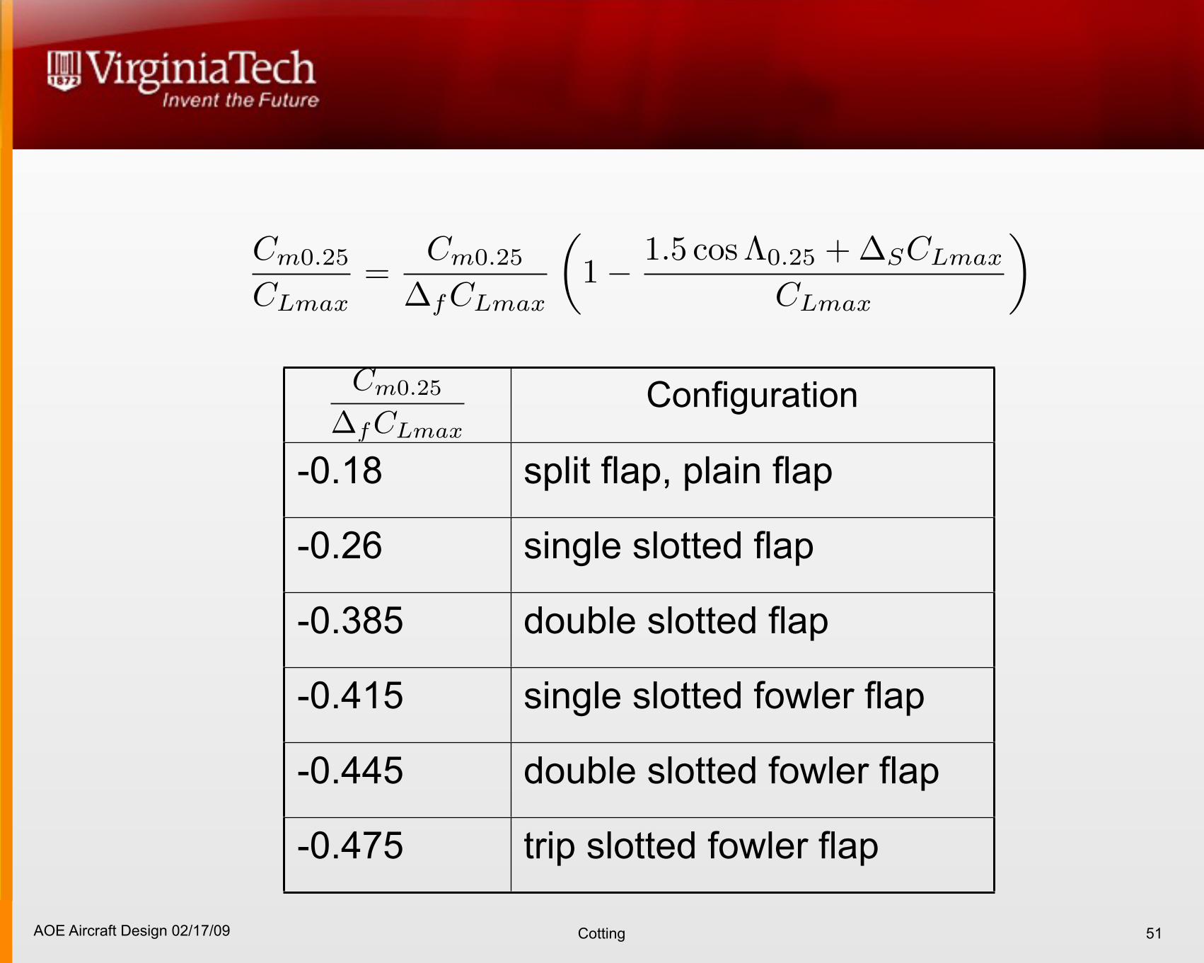
Configuration
-0.18 split flap, plain flap
-0.26 single slotted flap
-0.385 double slotted flap
-0.415 single slotted fowler flap
-0.445 double slotted fowler flap
-0.475 trip slotted fowler flap
AOE Aircraft Design 02/17/09 Cotting
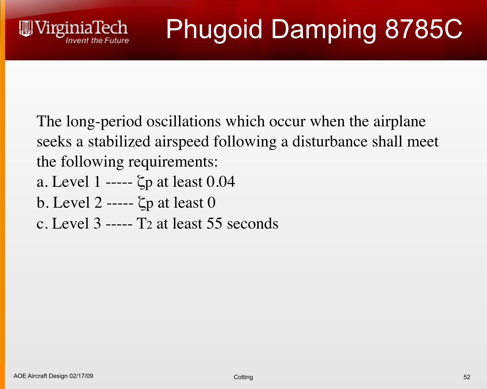
Phugoid Damping 8785C
52
The long-period oscillations which occur when the airplane seeks a stabilized airspeed following a disturbance shall meet the following requirements: a. Level 1 ----- ζp at least 0.04 b. Level 2 ----- ζp at least 0 c. Level 3 ----- T2 at least 55 seconds
AOE Aircraft Design 02/17/09 Cotting
Lateral/Directional Goals
Trim roll and yaw over flight envelope for required cross winds
Lateral/Directional cross coupling: adverse yaw of ailerons should not overpower directional stability
Favorable dutch roll frequencies and damping over flight envelope and weights
53
AOE Aircraft Design 02/17/09 Cotting
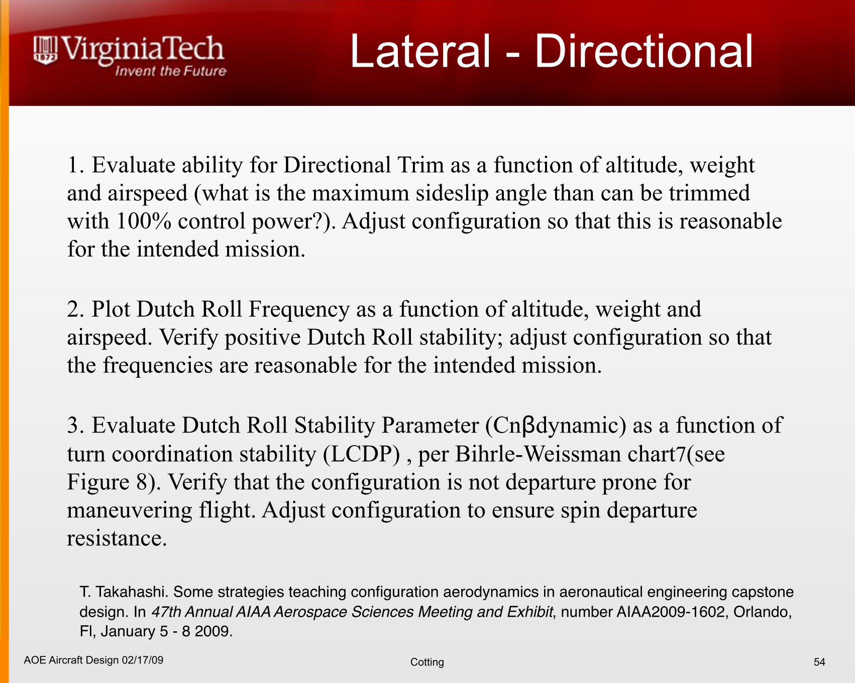
Lateral - Directional 1. Evaluate ability for Directional Trim as a function of altitude, weight and airspeed (what is the maximum sideslip angle than can be trimmed with 100% control power?). Adjust configuration so that this is reasonable for the intended mission.
2. Plot Dutch Roll Frequency as a function of altitude, weight and airspeed. Verify positive Dutch Roll stability; adjust configuration so that the frequencies are reasonable for the intended mission.
3. Evaluate Dutch Roll Stability Parameter (Cnβdynamic) as a function of turn coordination stability (LCDP) , per Bihrle-Weissman chart7(see Figure 8). Verify that the configuration is not departure prone for maneuvering flight. Adjust configuration to ensure spin departure resistance.
54
T. Takahashi. Some strategies teaching configuration aerodynamics in aeronautical engineering capstone design. In 47th Annual AIAA Aerospace Sciences Meeting and Exhibit, number AIAA2009-1602, Orlando, Fl, January 5 - 8 2009.
AOE Aircraft Design 02/17/09 Cotting
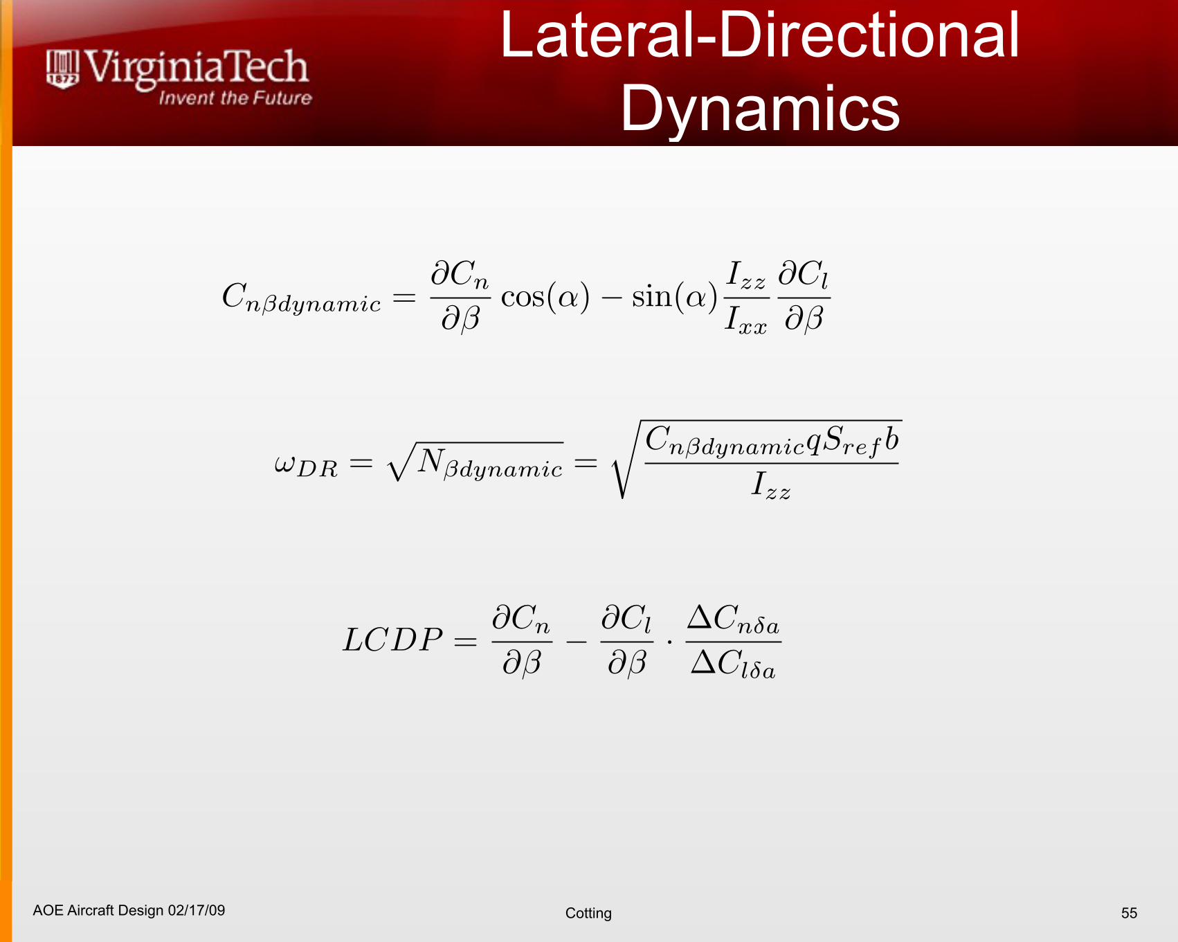
Lateral-Directional Dynamics
55
AOE Aircraft Design 02/17/09 Cotting 56
W. H. Mason High Angle-of-Attack Aerodynamics 9-9
3/10/06
-0.015
-0.010
-0.005
0.000
0.005
0.010
-0.015 -0.010 -0.005 0.000 0.005 0.010 0.015
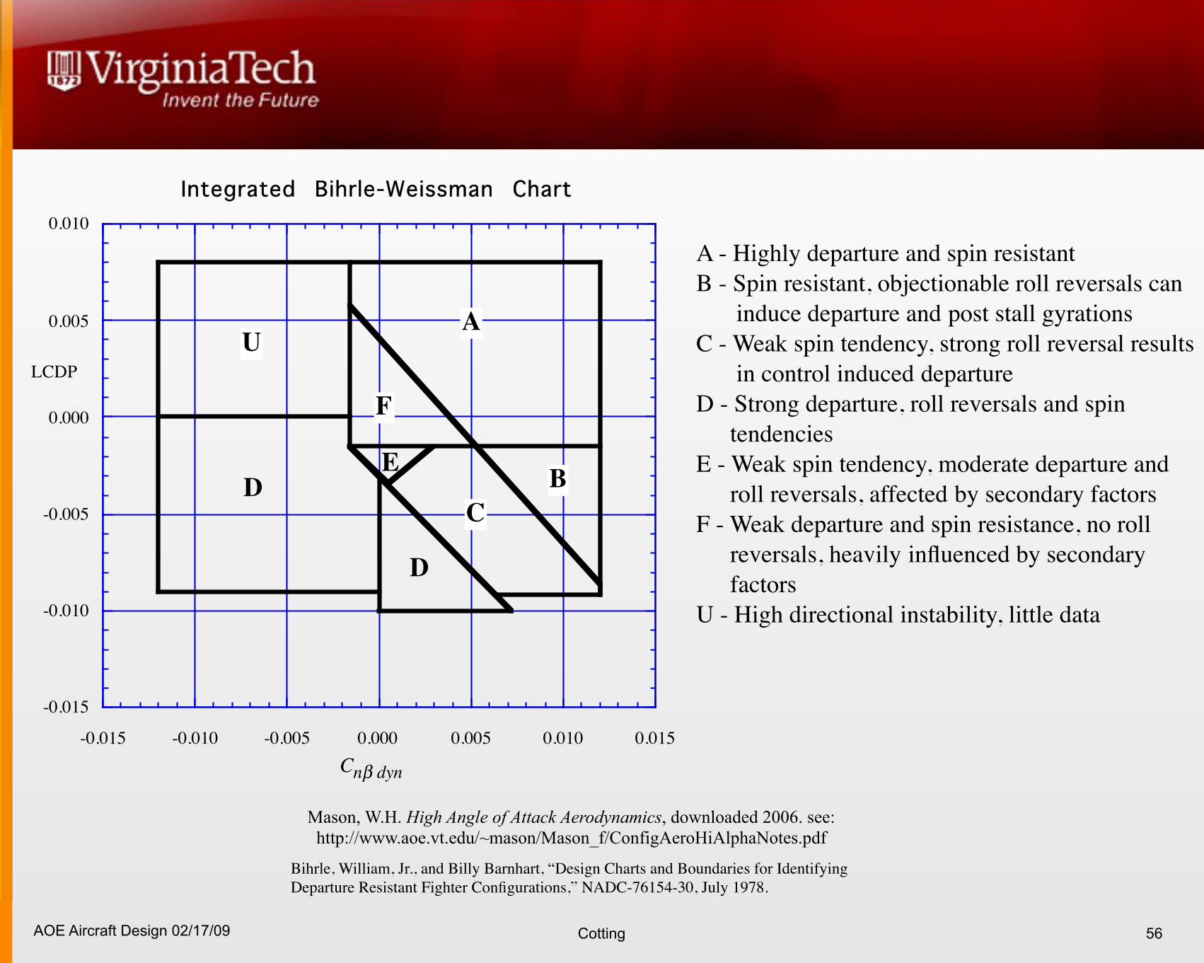
Integrated Bihrle-Weissman Chart
LCDP
Cn! dyn
AU
F
D BE
C
D
With following key: A - Highly departure and spin resistantB - Spin resistant, objectionable roll reversals can induce departure and
post stall gyrationsC - Weak spin tendency, strong roll reversal results in control induced
departureD - Strong departure, roll reversals and spin tendenciesE - Weak spin tendency, moderate departure and roll reversals, affected
by secondary factorsF - Weak departure and spin resistance, no roll reversals, heavily
influenced by secondary factorsU - High directional instability, little data
Figure 9-9. The Bihrle-Weissman chart (Ref. 15)
Bihrle, William, Jr., and Billy Barnhart, “Design Charts and Boundaries for Identifying Departure Resistant Fighter Configurations,” NADC-76154-30, July 1978.
A - Highly departure and spin resistant B - Spin resistant, objectionable roll reversals can
induce departure and post stall gyrations C - Weak spin tendency, strong roll reversal results
in control induced departure D - Strong departure, roll reversals and spin
tendencies E - Weak spin tendency, moderate departure and
roll reversals, affected by secondary factors F - Weak departure and spin resistance, no roll
reversals, heavily influenced by secondary factors
U - High directional instability, little data
Mason, W.H. High Angle of Attack Aerodynamics, downloaded 2006. see: http://www.aoe.vt.edu/~mason/Mason_f/ConfigAeroHiAlphaNotes.pdf
AOE Aircraft Design 02/17/09 Cotting
8785C Dutch Roll
57
MIL-F-8785C
3.3 Lateral-directional flying qualities
3.3.1 Lateral-directional mode characteristics
3.3.1.1 Lateral-directional oscillations (Dutch roll). The frequency, !nd
, and damping ratio, "d, of
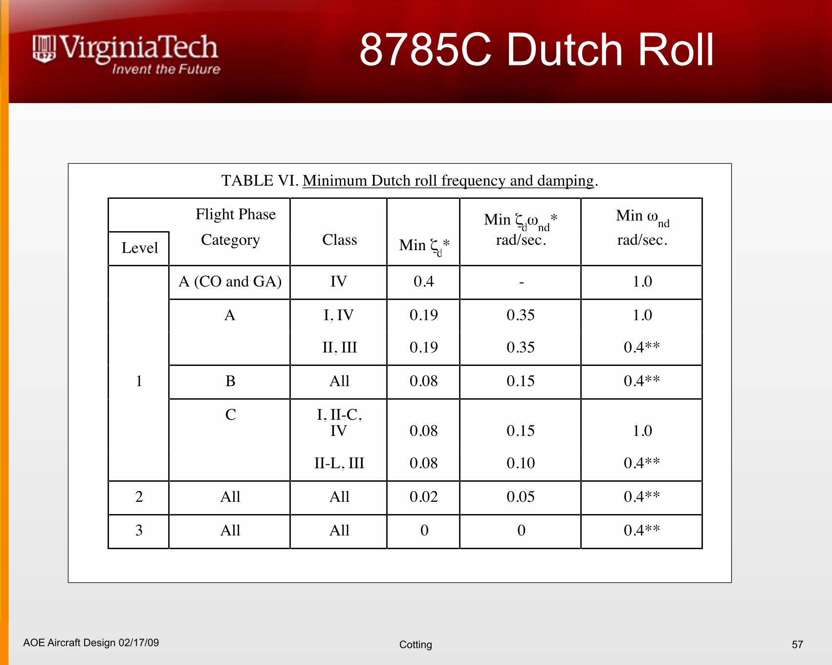
the lateral-directional oscillations following a yaw disturbance input shall exceed the minimumvalues in table VI. The requirements shall be met in trimmed and in maneuvering flight withcockpit controls fixed and with them free, in oscillations of any magnitude that might beexperienced in operational use. If the oscillation is nonlinear with amplitude, the requirementshall apply to each cycle of the oscillation. In calm air residual oscillations may be tolerated onlyif the amplitude is sufficiently small that the motions are not objectionable and do not impairmission performance. For Category A Flight Phases, angular deviations shall be less than ±3mils.
TABLE VI. Minimum Dutch roll frequency and damping.
Flight Phase Min "d!
nd* Min !
nd
LevelCategory Class Min "
d* rad/sec. rad/sec.
A (CO and GA) IV 0.4 - 1.0
A I, IV 0.19 0.35 1.0
II, III 0.19 0.35 0.4**
1 B All 0.08 0.15 0.4**
C I, II-C,IV 0.08 0.15 1.0
II-L, III 0.08 0.10 0.4**
2 All All 0.02 0.05 0.4**
3 All All 0 0 0.4**
* The governing damping requirement is that yielding the larger value of "d, except that "
dof 0.7 is the maximum required for Class III.
** Class III airplanes may be excepted from the minimum !nd
requirement, subject to
approval by the procuring activity, if the requirements of 3.3.2 through 3.3.2.4.1, 3.3.5and 3.3.9.4 are met.
When !nd2 #/$
d is greater than 20 (rad/sec)2, the minimum "
d!
nd shall be increased
above the "d!
nd minimums listed above by:
Level 1 - %"d!
nd = .014 !
nd2 #/$
d - 20
Level 2 - %"d!
nd = .009 !
nd2 #/$
d - 20
Level 3 - %"d!
nd = .004 !
nd2 #/$
d - 20
with !nd
in rad/sec.
22
AOE Aircraft Design 02/17/09 Cotting
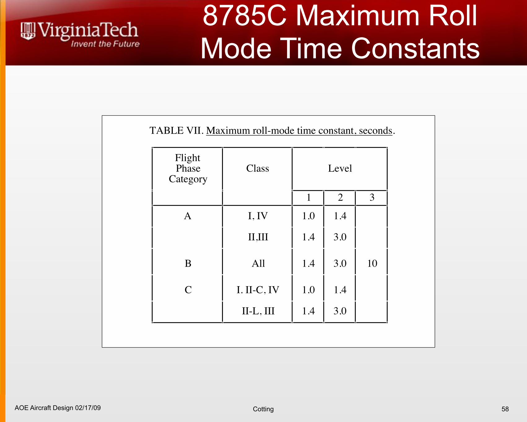
8785C Maximum Roll Mode Time Constants
58
MIL-F-8785C
3.3.1.2 Roll mode. The roll-mode time constant, !R, shall be no greater than the appropriatevalue in table VII.
TABLE VII. Maximum roll-mode time constant, seconds.
FlightPhase
CategoryClass Level
1 2 3
A I, IV 1.0 1.4
II,III 1.4 3.0
B All 1.4 3.0 10
C I. II-C, IV 1.0 1.4
II-L, III 1.4 3.0
3.3.1.3 Spiral stability. The combined effects of spiral stability, flight-control-systemcharacteristics and rolling moment change with speed shall be such that following a disturbancein bank of up to 20 degrees, the time for the bank angle to double shall be greater than the valuesin table VIII. This requirement shall be met with the airplane trimmed for wings-level, zero-yaw-rate flight with the cockpit controls free.
TABLE VIII. Spiral stability - minimum time to double amplitude.
Flight PhaseCategory Level 1 Level 2 Level 3
A & C 12 sec 8 sec 4 sec
B 20 sec 8 sec 4 sec
3.3.1.4 Coupled roll-spiral oscillation. For Flight Phases which involve more than gentlemaneuvering, such as CO and GA, the airplane characteristics shall not exhibit a coupled roll-spiral mode in response to the pilot roll control commands. A coupled roll-spiral mode will bepermitted for Category B and C Flight Phases provided the product of frequency and dampingratio exceeds the following requirements:
Level "RS#
nRS
, rad/sec
1 0.5
2 0.3
3 0.15
23
AOE Aircraft Design 02/17/09 Cotting
Crosswind Landing
59
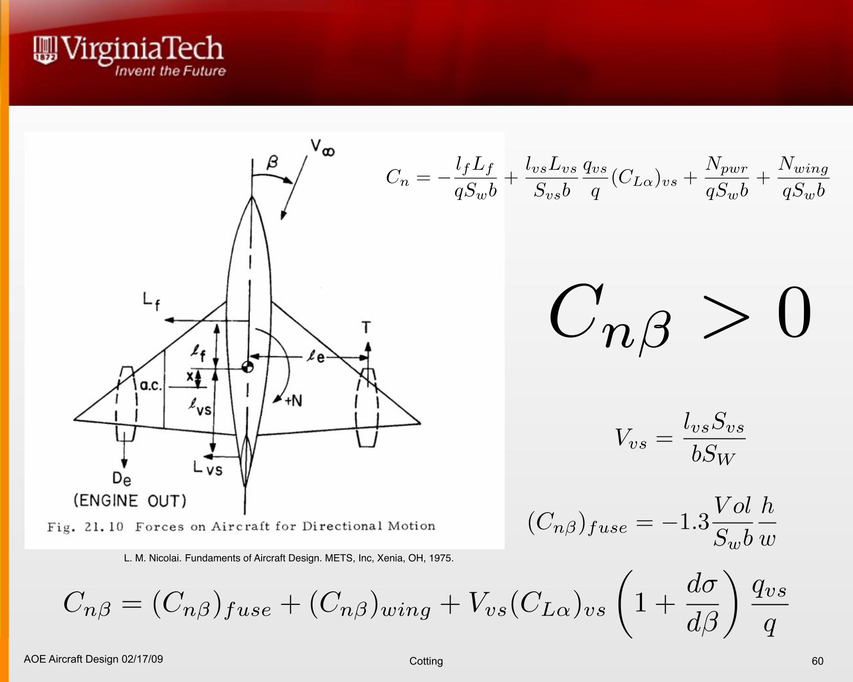
AOE Aircraft Design 02/17/09 Cotting 60
L. M. Nicolai. Fundaments of Aircraft Design. METS, Inc, Xenia, OH, 1975.
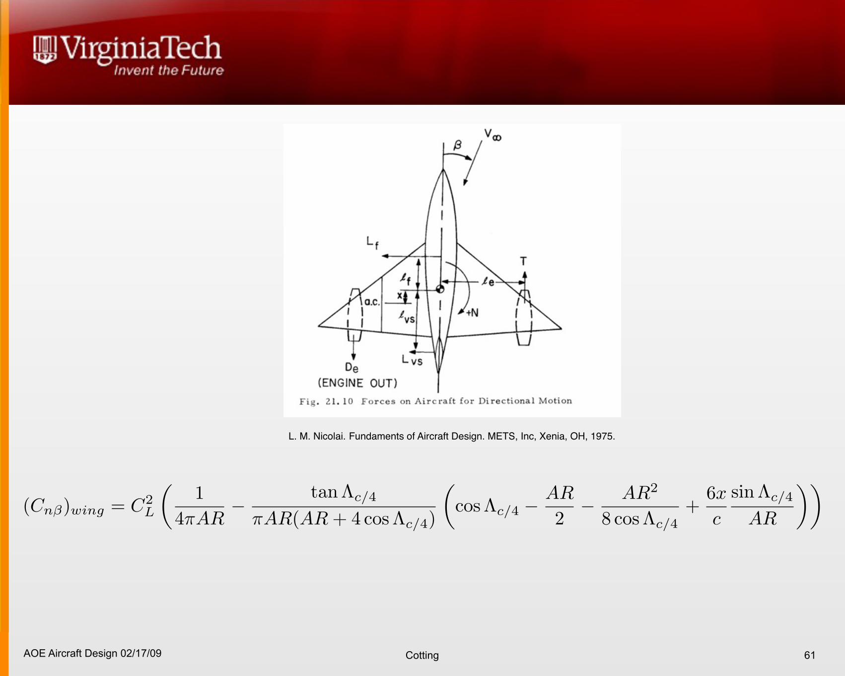
AOE Aircraft Design 02/17/09 Cotting 61
L. M. Nicolai. Fundaments of Aircraft Design. METS, Inc, Xenia, OH, 1975.
AOE Aircraft Design 02/17/09 Cotting
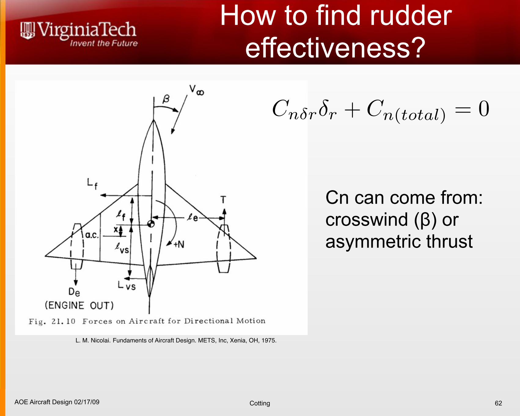
How to find rudder effectiveness?
62
L. M. Nicolai. Fundaments of Aircraft Design. METS, Inc, Xenia, OH, 1975.
Cn can come from: crosswind (β) or asymmetric thrust
AOE Aircraft Design 02/17/09 Cotting
References
63
D. McRuer, I. Ashkenas, and D. Graham. Aircraft Dynamics and Automatic Control. Princeton University Press, Princeton, New Jersey, 1973.
C. D. Perkins and R. E. Hage. Airplane Performance Stability and Control. John Wiley and Sons, Princeton, New Jersey, 1949.
L. M. Nicolai. Fundaments of Aircraft Design. METS, Inc, Xenia, OH, 1975.
B. Etkin. Dynamics of Flight, Stability and Control. John Wiley and Sons, New York, NY, second edition, 1982.
J. Roskam. Airplane Flight Dynamics and Automatic Flight Controls. Roskam Aviation and Engineering Corperation, Lawrence, Kansas, 1979.
J. Roskam. Airplane Design, volume IV. Roskam Aviation and Engineering Corperation, Ottowa, Kansas, 1986.
B. Stevens and F. Lewis. Aircraft Control and Simulation. John Wiley and Sons, New York, NY, 1st edition, 1992.
D. P. Raymer. Aircraft Design: A Conceptual Approach. AIAA Education Series, Alexandria, Va., second edition, 1992.
T. Takahashi. Some strategies teaching configuration aerodynamics in aeronautical engineering capstone design. In 47th Annual AIAA Aerospace Sciences Meeting and Exhibit, AIAA2009-1602, Orlando, Fl, January 5 - 8 2009.
Mason, W.H. High Angle of Attack Aerodynamics, downloaded 2009. see: http://www.aoe.vt.edu/~mason/Mason_f/ConfigAeroHiAlphaNotes.pdf
Mason, W.H. Control and Stability in Aircraft Conceptual Design, downloaded 2009. see: http://www.aoe.vt.edu/aoe/faculty/Mason_f/SD1L13.pdf
AOE Aircraft Design 02/17/09 Cotting 64