Embed Size (px)
Citation preview
7866 Digital Thermal Conductivity Analyzer for Binary Gas Mixtures Specifications 70-82-03-46 October 2006
Overview
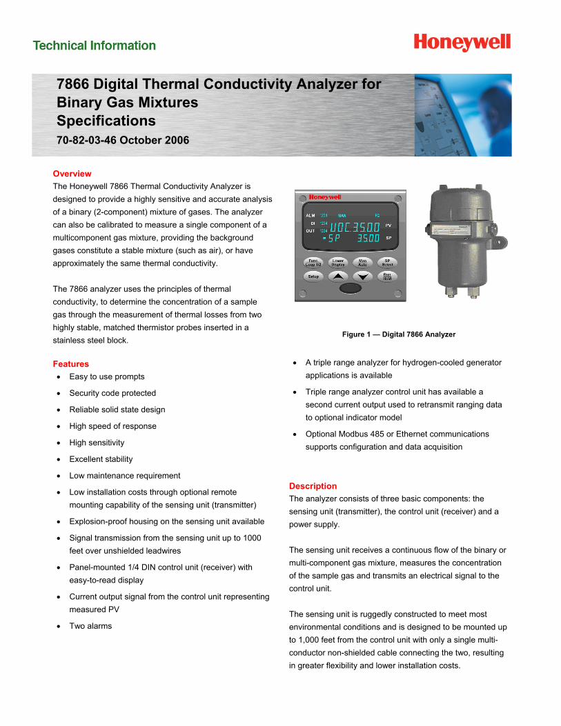
The Honeywell 7866 Thermal Conductivity Analyzer is
designed to provide a highly sensitive and accurate analysis
of a binary (2-component) mixture of gases. The analyzer
can also be calibrated to measure a single component of a
multicomponent gas mixture, providing the background
gases constitute a stable mixture (such as air), or have
approximately the same thermal conductivity.
The 7866 analyzer uses the principles of thermal
conductivity, to determine the concentration of a sample
gas through the measurement of thermal losses from two
highly stable, matched thermistor probes inserted in a
stainless steel block.
Features
Easy to use prompts
Security code protected
Reliable solid state design
High speed of response
High sensitivity
Excellent stability
Low maintenance requirement
Low installation costs through optional remote
mounting capability of the sensing unit (transmitter)
Explosion-proof housing on the sensing unit available
Signal transmission from the sensing unit up to 1000
feet over unshielded leadwires
Panel-mounted 1/4 DIN control unit (receiver) with
easy-to-read display
Current output signal from the control unit representing
measured PV
Two alarms
Figure 1 — Digital 7866 Analyzer
A triple range analyzer for hydrogen-cooled generator
applications is available
Triple range analyzer control unit has available a
second current output used to retransmit ranging data
to optional indicator model
Optional Modbus 485 or Ethernet communications
supports configuration and data acquisition
Description
The analyzer consists of three basic components: the
sensing unit (transmitter), the control unit (receiver) and a
power supply.
The sensing unit receives a continuous flow of the binary or
multi-component gas mixture, measures the concentration
of the sample gas and transmits an electrical signal to the
control unit.
The sensing unit is ruggedly constructed to meet most
environmental conditions and is designed to be mounted up
to 1,000 feet from the control unit with only a single multi-
conductor non-shielded cable connecting the two, resulting
in greater flexibility and lower installation costs.
HFS Catalog_Without Tab_HighRes.pdf 51 6/8/2011 12:41:06 PM

7866 Digital Thermal Conductivity Analyzer for Binary Gas Mixtures 2
The control unit receives the output signal from the sensing
unit at the sampling site by way of the inter-connecting
cable.
The control unit is designed for simplified panel-mounting
either at the sampling site, if environmental conditions
permit, or in a control room. The unit provides a current
output signal to a remote device for monitoring or recording
purposes.
The control unit is supplied with two alarms. When there is
no “alarm” condition, the relay is energized, so the NO
contacts are closed and the NC contacts are open. When
an alarm condition occurs, the relay de-energizes, so the
NO contact falls open, and the NC contact falls closed.
This is a normal “FAILSAFE” contact operation. If you lose
power, the relays obviously DEENERGIZE, so the relays
fall to their ALARM condition, providing “failsafe” indication
that the controller is not operating.
An indicator model, which provides a continuous readout of
the concentration of the gas under analysis, is available
with the triple range 7866 analyzer. The indicator input is
connected to the controller's current output. The indicator
has no direct connection to the sensing unit.
Some common applications of the 7866 Thermal
Conductivity Analyzer are:
Electric Power Industry Power Plants – Accurate
monitoring of hydrogen purity in hydrogen-cooled
generators. The triple range analyzer also monitors
carbon dioxide in air and carbon dioxide in hydrogen
insuring safe execution of the purge cycles.
Chemical Industry – Measurement of hydrogen in
ammonia or nitrogen for dissociated ammonia
applications. Also, measurement of hydrogen in
oxygen, carbon dioxide, and methane.
Petroleum Industry – Measurement of hydrogen in
certain hydrocarbon streams.
Equipment
Sensing Unit – The 7866 Thermal Conductivity analyzer’s
sensor assembly is supplied with an optional explosion
proof housing. The housing consists of a rugged cast
aluminum construction that permits reliable operation under
adverse ambient conditions.
The sensor assembly consists of two sections – the cell
block assembly and the electronic assembly.
The cell block assembly is of stainless steel construction
with two identical internal cells, the measuring cell and the
reference cell. The highly stable thermistor is mounted in
each cell. These matched thermistors form the active arms
of a bridge circuit. The unbalanced current of the bridge
provides the means of measuring the relative ability of the
sample and reference gases to conduct the heat away from
their respective thermistors to the cell wall, which is held at
a constant temperature. The reference gas chamber, with
inlet and outlet openings drilled into the chamber from the
base, can be opened or sealed. All zero-based standard
ranges and the 20% to 50% H2 range have air-filled, sealed
reference cells. For hydrogen ranges starting above 50% as
well as the 90-100% oxygen range, a flowing reference is
used. The measuring chamber is open to the continuous
sample gas flow.
The cells in which the thermistors are mounted are dead-
ended so the sample gas enters only by diffusion,
minimizing the effect of sample flow variations. In addition,
the entire cell-block assembly is maintained at a constant
optimum temperature through two heaters and a control
thermistor that are located in the cell block assembly.
The sensing unit’s electronics assembly incorporates solid
state electrical circuits. These circuits include:
Current Regulator which supplies the constant current
to the thermistor cell bridge circuit.
Proportional Action Temperature Controller which
maintains the entire cell block at a constant
temperature.
Voltage to Current Converter/ Amplifier whose current
output is transmitted to the analyzer’s Control Unit.
S ens ing U n it
(Trans m it t e r)C o n t rol
U n it (R e c e iv e r)U p
to
1000'
S am p ling S it e C o n t r o l
Room
C o m m onO pe ra ting
V olt age
M e a s ured S ign als
M u lt i- C on du c t o r C able
Power supply
HFS Catalog_Without Tab_HighRes.pdf 52 6/8/2011 12:41:06 PM

7866 Digital Thermal Conductivity Analyzer for Binary Gas Mixtures 3
Control Unit – The control unit houses the remaining
measuring circuits in a 1/4 DIN standard case. In addition,
the control unit has a digital display (4 digit display of
Process Variable as well as range indication and alarm
status) with keypad and a menu structure to enable easy
configuration and calibration. It provides 4-20mA output
and 2 form C relay contacts for Alarms.
Digital Display on the Control Unit – Provides a continuous
readout of the concentration (0-100 %) of the gas under
analysis.
Alarms – Two alarms are available for high and low alarms.
Each alarm can be individually set. An alarm hysteresis
which sets the deactivation range for both alarms is also
available. The alarms include numeric indication on the
display, as well as, an external relay contact for external
communication. The relay output can also service an
external shutdown device.
Optional Communications – Allows the controller to be
connected to a host computer via the Modbus 485 protocol
or Ethernet communication.
When measuring flammable gas mixture that contains
oxygen, the maximum oxygen concentration must not
exceed 21%.
HFS Catalog_Without Tab_HighRes.pdf 53 6/8/2011 12:41:06 PM

7866 Digital Thermal Conductivity Analyzer for Binary Gas Mixtures 4
Operator Interface
Figure 2 – 7866 Control Unit Operator Interface and Key Functions
Display Indicators
3200 3500
Upper display with 4 larger digits shows Process Variable value (normal operation) and special annunciator features. During Configuration, the upper display provides guidance for the operator through prompts (7 – characters)
OUT Control Relay 1 through 4 annunciations.
SP 3500
During normal operation, the lower display shows key-selected operating parameters such as Output, Setpoints, Inputs, Deviation, active Tuning Parameter Set, Timer Status, or minutes remaining in a setpoint ramp (4 digits). During configuration, the lower display provides guidance for the operator through prompts (8-characters).
FF
or CC
Indicates either degrees Fahrenheit or Centigrade.
ALMALM
Alarm 1 through 4 annunciations. MAN
or AA
Indicates either Manual
or
Auto mode.
DIDI
Digital Input 1 through 4 annunciations. SPSP
Indicates Local Setpoint #1. The lower display also shows other control information and other setpoints. A bar is lighted next to the lower display when the setpoint currently being used is shown on the lower display.
Keys and Functions Func
Loop 1/2
Selects functions within each configuration group. Switches between Loop Displays for Two Loop and Cascade units.
ManAutoManAutoManAuto
Selects Manual or Auto mode.
SetupSetupScrolls through the configuration groups. SP
SelectSP
SelectSP
Select
Hold key down to cycle through configured setpoints.
LowerDisplayLower
DisplayLower
Display
Returns Controller to normal display from Set Up mode. Toggles various operating parameters for display.
RunHoldRunHoldRunHold
Enables Run/Hold of the SP Ramp or Program plus Timer start.
Increases setpoint or output value. Increases the configuration values or changes functions in Configuration mode groups.
Decreases setpoint or output value. Decreases the configuration values or changes functions in Configuration mode groups.
Infrared transceiver
NEMA4X and IP66 screw attachment (each corner)
HFS Catalog_Without Tab_HighRes.pdf 54 6/8/2011 12:41:06 PM

7866 Digital Thermal Conductivity Analyzer for Binary Gas Mixtures 5
Ethernet Communications
Widely used by manufacturers, the Ethernet connection, which uses Modbus TCP/IP, allows the controller to connect to
other Ethernet networks and exchange data with computers or devices on that network for monitoring or managing your
process from almost any location. The Ethernet cable can be connected to a hub (using a straight through cable) or
directly to a PC (using a crossed cable or straight through cable reconfigured at the controller terminals)
The controller can be configured via the P.I.E. software. This software allows the user to configure all of the parameters
included in the instrument and to monitor various parameters in the controller.
The controller can be configured to send an Email when an alarm condition has been encountered. The Email address
and gateway are configured using the P.I.E. software.
HFS Catalog_Without Tab_HighRes.pdf 55 6/8/2011 12:41:06 PM

7866 Digital Thermal Conductivity Analyzer for Binary Gas Mixtures 6
Figure 3 — 7866 Sensor Assembly
HFS Catalog_Without Tab_HighRes.pdf 56 6/8/2011 12:41:06 PM

7866 Digital Thermal Conductivity Analyzer for Binary Gas Mixtures 7
Figure 4 – Block Diagram of 7866 Digital Thermal Conductivity Analyzer
Figure 5 — Cross-Section of 7866 Sensing Unit
HFS Catalog_Without Tab_HighRes.pdf 57 6/8/2011 12:41:06 PM
7866 Digital Thermal Conductivity Analyzer for Binary Gas Mixtures 8
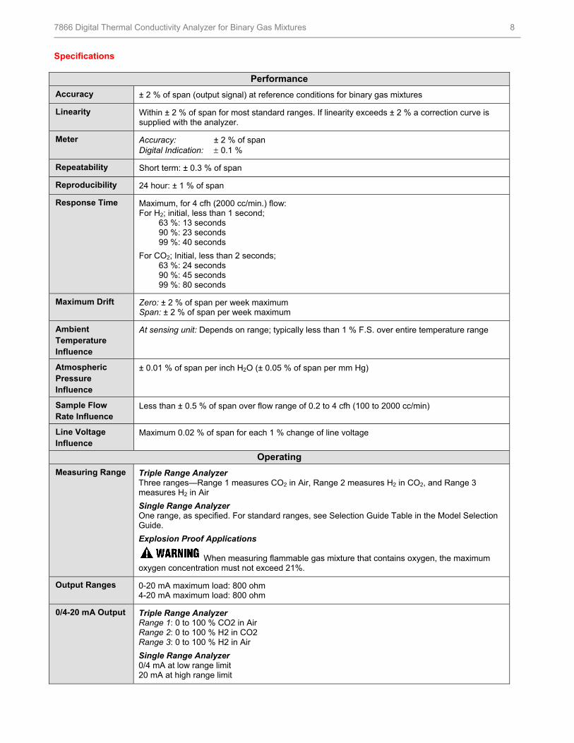
Specifications
Performance
Accuracy ± 2 % of span (output signal) at reference conditions for binary gas mixtures
Linearity Within ± 2 % of span for most standard ranges. If linearity exceeds ± 2 % a correction curve is supplied with the analyzer.
Meter Accuracy: ± 2 % of span Digital Indication: 0.1 %
Repeatability Short term: ± 0.3 % of span
Reproducibility 24 hour: ± 1 % of span
Response Time Maximum, for 4 cfh (2000 cc/min.) flow: For H2; initial, less than 1 second; 63 %: 13 seconds 90 %: 23 seconds 99 %: 40 seconds
For CO2; Initial, less than 2 seconds; 63 %: 24 seconds 90 %: 45 seconds 99 %: 80 seconds
Maximum Drift Zero: ± 2 % of span per week maximum Span: ± 2 % of span per week maximum
Ambient Temperature Influence
At sensing unit: Depends on range; typically less than 1 % F.S. over entire temperature range
Atmospheric Pressure Influence
± 0.01 % of span per inch H2O (± 0.05 % of span per mm Hg)
Sample Flow Rate Influence
Less than ± 0.5 % of span over flow range of 0.2 to 4 cfh (100 to 2000 cc/min)
Line Voltage Influence
Maximum 0.02 % of span for each 1 % change of line voltage
Operating
Measuring Range Triple Range Analyzer Three ranges—Range 1 measures CO2 in Air, Range 2 measures H2 in CO2, and Range 3 measures H2 in Air
Single Range Analyzer One range, as specified. For standard ranges, see Selection Guide Table in the Model Selection Guide.
Explosion Proof Applications
When measuring flammable gas mixture that contains oxygen, the maximum oxygen concentration must not exceed 21%.
Output Ranges 0-20 mA maximum load: 800 ohm 4-20 mA maximum load: 800 ohm
0/4-20 mA Output Triple Range Analyzer Range 1: 0 to 100 % CO2 in Air Range 2: 0 to 100 % H2 in CO2 Range 3: 0 to 100 % H2 in Air
Single Range Analyzer 0/4 mA at low range limit 20 mA at high range limit
HFS Catalog_Without Tab_HighRes.pdf 58 6/8/2011 12:41:06 PM
7866 Digital Thermal Conductivity Analyzer for Binary Gas Mixtures 9
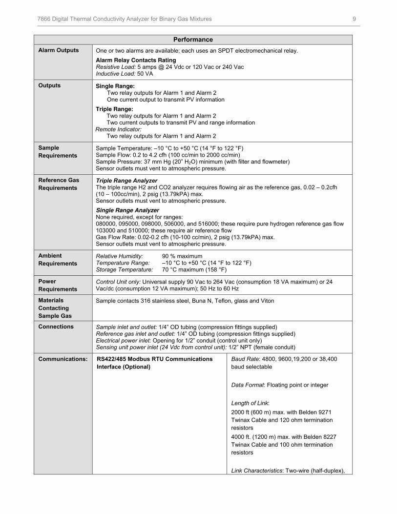
Performance
Alarm Outputs One or two alarms are available; each uses an SPDT electromechanical relay.
Alarm Relay Contacts Rating Resistive Load: 5 amps @ 24 Vdc or 120 Vac or 240 Vac Inductive Load: 50 VA
Outputs Single Range: Two relay outputs for Alarm 1 and Alarm 2 One current output to transmit PV information
Triple Range: Two relay outputs for Alarm 1 and Alarm 2 Two current outputs to transmit PV and range information Remote Indicator: Two relay outputs for Alarm 1 and Alarm 2
Sample Requirements
Sample Temperature: –10 °C to +50 °C (14 °F to 122 °F) Sample Flow: 0.2 to 4.2 cfh (100 cc/min to 2000 cc/min) Sample Pressure: 37 mm Hg (20” H2O) minimum (with filter and flowmeter) Sensor outlets must vent to atmospheric pressure.
Reference Gas Requirements
Triple Range Analyzer The triple range H2 and CO2 analyzer requires flowing air as the reference gas, 0.02 – 0.2cfh (10 – 100cc/min), 2 psig (13.79kPA) max. Sensor outlets must vent to atmospheric pressure.
Single Range Analyzer None required, except for ranges: 080000, 095000, 098000, 506000, and 516000; these require pure hydrogen reference gas flow 103000 and 510000; these require air reference flow Gas Flow Rate: 0.02-0.2 cfh (10-100 cc/min), 2 psig (13.79kPA) max. Sensor outlets must vent to atmospheric pressure.
Ambient Requirements
Relative Humidity: 90 % maximum Temperature Range: –10 °C to +50 °C (14 °F to 122 °F) Storage Temperature: 70 °C maximum (158 °F)
Power Requirements
Control Unit only: Universal supply 90 Vac to 264 Vac (consumption 18 VA maximum) or 24 Vac/dc (consumption 12 VA maximum); 50 Hz to 60 Hz
Materials Contacting Sample Gas
Sample contacts 316 stainless steel, Buna N, Teflon, glass and Viton
Connections Sample inlet and outlet: 1/4” OD tubing (compression fittings supplied) Reference gas inlet and outlet: 1/4” OD tubing (compression fittings supplied) Electrical power inlet: Opening for 1/2” conduit (control unit only) Sensing unit power inlet (24 Vdc from control unit): 1/2” NPT (female conduit)
Communications: RS422/485 Modbus RTU Communications Interface (Optional)
Baud Rate: 4800, 9600,19,200 or 38,400 baud selectable
Data Format: Floating point or integer
Length of Link:
2000 ft (600 m) max. with Belden 9271 Twinax Cable and 120 ohm termination resistors
4000 ft. (1200 m) max. with Belden 8227 Twinax Cable and 100 ohm termination resistors
Link Characteristics: Two-wire (half-duplex),
HFS Catalog_Without Tab_HighRes.pdf 59 6/8/2011 12:41:06 PM
7866 Digital Thermal Conductivity Analyzer for Binary Gas Mixtures 10
Performance
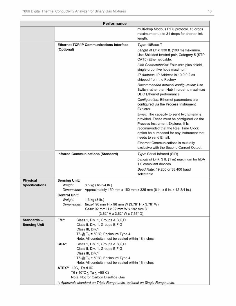
multi-drop Modbus RTU protocol, 15 drops maximum or up to 31 drops for shorter link length.
Ethernet TCP/IP Communications Interface (Optional)
Type: 10Base-T
Length of Link: 330 ft. (100 m) maximum. Use Shielded twisted-pair, Category 5 (STP CAT5) Ethernet cable.
Link Characteristics: Four-wire plus shield, single drop, five hops maximum
IP Address: IP Address is 10.0.0.2 as shipped from the Factory
Recommended network configuration: Use Switch rather than Hub in order to maximize UDC Ethernet performance
Configuration: Ethernet parameters are configured via the Process Instrument Explorer.
Email: The capacity to send two Emails is provided. These must be configured via the Process Instrument Explorer. It is recommended that the Real Time Clock option be purchased for any instrument that needs to send Email.
Ethernet Communications is mutually exclusive with the Second Current Output.
Infrared Communications (Standard) Type: Serial Infrared (SIR)
Length of Link: 3 ft. (1 m) maximum for IrDA 1.0 compliant devices
Baud Rate: 19,200 or 38,400 baud selectable
Physical Specifications
Sensing Unit: Weight: 8.5 kg (18-3/4 lb.) Dimensions: Approximately 150 mm x 150 mm x 325 mm (6 in. x 6 in. x 12-3/4 in.)
Control Unit: Weight: 1.3 kg (3 lb.) Dimensions: Bezel: 96 mm H x 96 mm W (3.78” H x 3.78” W) Case: 92 mm H x 92 mm W x 192 mm D (3.62” H x 3.62” W x 7.55” D)
Standards – Sensing Unit
FM*: Class 1, Div. 1, Groups A,B,C,D Class II, Div. 1, Groups E,F,G Class III, Div.1 T6 @ TA = 50°C; Enclosure Type 4 Note: All conduits must be sealed within 18 inches
CSA*: Class 1, Div. 1, Groups A,B,C,D Class II, Div. 1, Groups E,F,G Class III, Div.1 T6 @ TA = 50°C; Enclosure Type 4 Note: All conduits must be sealed within 18 inches
ATEX**: II2G, Ex d IIC T6 (-10oC < Ta < +50oC) Note: Not for Carbon Disulfide Gas
*: Approvals standard on Triple Range units, optional on Single Range units.
HFS Catalog_Without Tab_HighRes.pdf 60 6/8/2011 12:41:06 PM

7866 Digital Thermal Conductivity Analyzer for Binary Gas Mixtures 11
Performance
**: Only available on Triple Range units See Model Selection Guide for details.
Standards – Control Unit
This product is in conformity with the protection requirements of the following European Council Directives: 73/23/EEC, the Low Voltage Directive, and 89/336/EEC, the EMC Directive. Conformity of this product with any other “CE Mark” Directive(s) shall not be assumed.
Product Classification:
Class I: Permanently connected, panel-mounted Industrial Control Equipment with protective earthing (grounding).
Enclosure Rating: Panel-mounted equipment. This controller must be panel-mounted. Terminals must be enclosed within the panel. Front Bezel: NEMA3R and IP54, or NEMA4X and IP66 with 4 screws. UL and CSA approved as Type 4 moisture protection when used with 4 screws.
Installation Category (Overvoltage Category):
Category II: Energy-consuming equipment supplied from the fixed installation, local level appliances, and Industrial Control Equipment.
Pollution Degree: Pollution Degree 2: Normally non-conductive pollution with occasional conductivity caused by condensation. (Ref. IEC 664-1)
EMC Classification: Group 1, Class A, ISM Equipment (EN55011, emissions), Industrial Equipment (EN61326, immunity)
Method of EMC Assessment:
Technical File (TF)
Declaration of Conformity:
51453681
Miscellaneous Analyzer temperature: Sensing unit thermostated at 50 °C (122 °F)
HFS Catalog_Without Tab_HighRes.pdf 61 6/8/2011 12:41:07 PM
7866 Digital Thermal Conductivity Analyzer for Binary Gas Mixtures 12
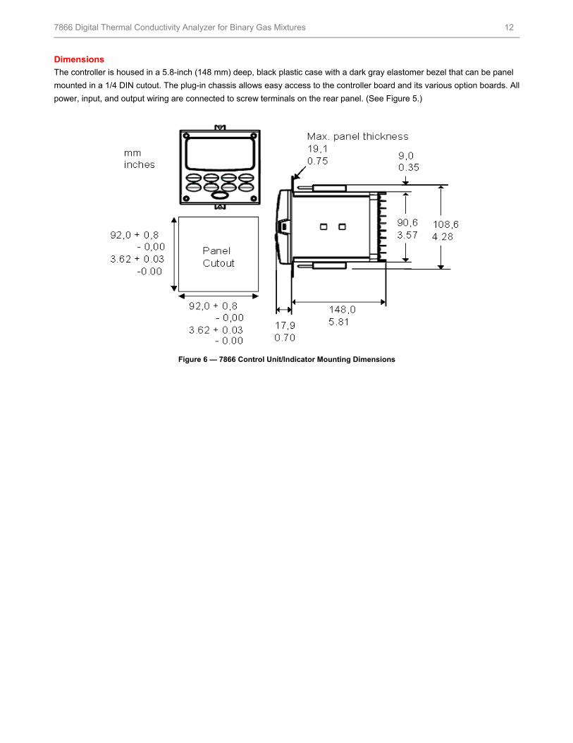
Dimensions
The controller is housed in a 5.8-inch (148 mm) deep, black plastic case with a dark gray elastomer bezel that can be panel
mounted in a 1/4 DIN cutout. The plug-in chassis allows easy access to the controller board and its various option boards. All
power, input, and output wiring are connected to screw terminals on the rear panel. (See Figure 5.)
Figure 6 — 7866 Control Unit/Indicator Mounting Dimensions
HFS Catalog_Without Tab_HighRes.pdf 62 6/8/2011 12:41:07 PM
7866 Digital Thermal Conductivity Analyzer for Binary Gas Mixtures 13
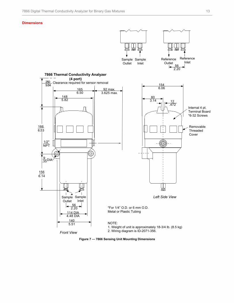
Dimensions
Figure 7 — 7866 Sensing Unit Mounting Dimensions
Clearance required for sensor removal2509.84
1656.50
92 max.3.625 max.
1485.82
9.35DIA.
562.20
*
114 DIA4.48 DIA
1405.51
1546.06
803.14
1666.53
1566.14
SampleInlet
7866 Thermal Conductivity Analyzer(4 port)
1/2"NPT
12.472
SampleOutlet
ReferenceOutlet
ReferenceInlet
562.20
SampleInlet
SampleOutlet
Front View
Left Side View
Internal 4 pt.Terminal Board*6-32 Screws
RemovableThreadedCover
*For 1/4” O.D. or 6 mm O.D.Metal or Plastic Tubing
NOTE:1. Weight of unit is approximately 18-3/4 lb. (8.5 kg)2. Wiring diagram is ID-2071-356.
HFS Catalog_Without Tab_HighRes.pdf 63 6/8/2011 12:41:07 PM

7866 Digital Thermal Conductivity Analyzer for Binary Gas Mixtures 14
For More Information
Learn more about how Honeywell’s 7866 Digital
Thermal Conductivity Analyzer for Binary Gas Mixtures
can provide accurate analysis of binary component,
visit our website www.honeywell.com/ps/hfs or contact
your Honeywell account manager.
Honeywell Process Solutions
1860 West Rose Garden Lane
Phoenix, Arizona 85027
Tel: 1-800-423-9883 or 1-800-343-0228
www.honeywell.com/ps
Warranty/Remedy
Honeywell warrants goods of its manufacture as being free of defective materials and faulty workmanship. Contact your local
sales office for warranty information. If warranted goods are returned to Honeywell during the period of coverage, Honeywell
will repair or replace without charge those items it finds defective. The foregoing is Buyer's sole remedy and is in lieu of all
other warranties, expressed or implied, including those of merchantability and fitness for a particular purpose.
Specifications may change without notice. The information we supply is believed to be accurate and reliable as of this
printing. However, we assume no responsibility for its use.
While we provide application assistance personally, through our literature and the Honeywell web site, it is up to the
customer to determine the suitability of the product in the application.
70-82-03-46 October 2006 © 2010 Honeywell International Inc.
HFS Catalog_Without Tab_HighRes.pdf 64 6/8/2011 12:41:07 PM
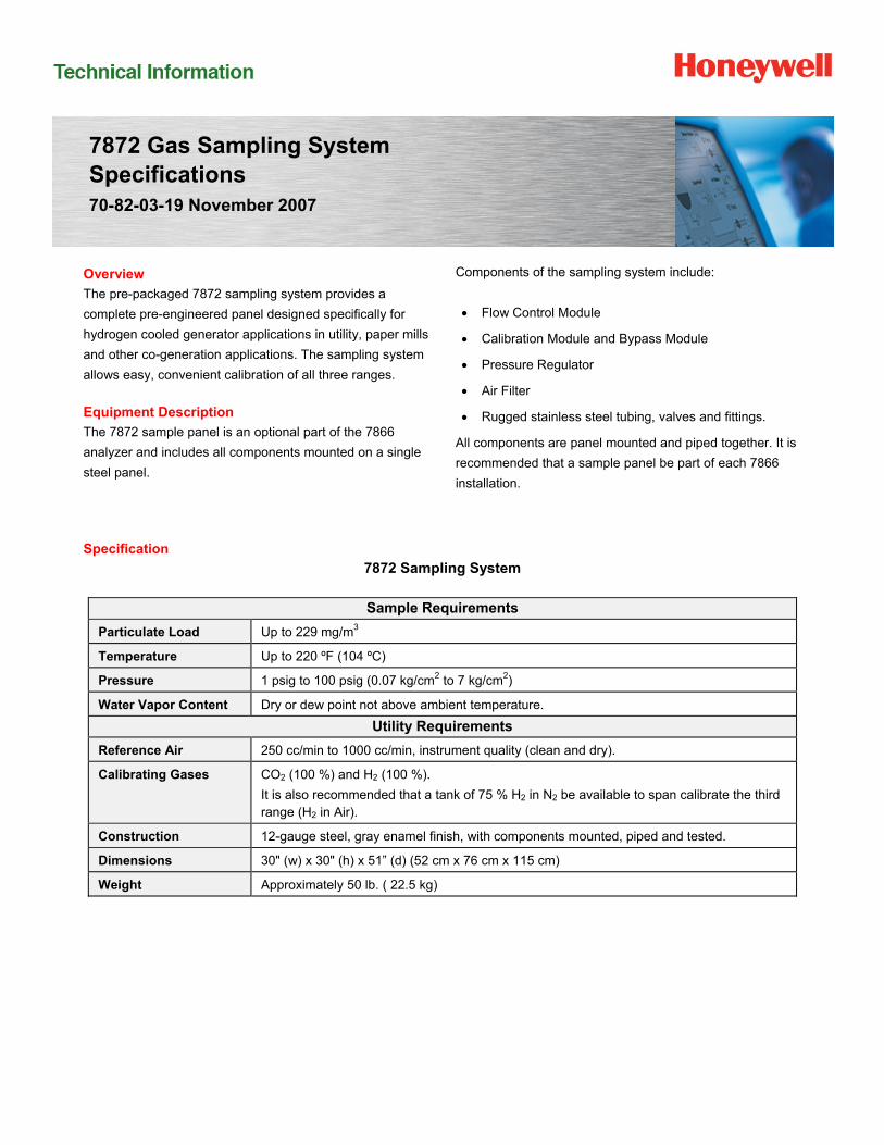
7872 Gas Sampling System Specifications 70-82-03-19 November 2007
Overview
The pre-packaged 7872 sampling system provides a
complete pre-engineered panel designed specifically for
hydrogen cooled generator applications in utility, paper mills
and other co-generation applications. The sampling system
allows easy, convenient calibration of all three ranges.
Equipment Description
The 7872 sample panel is an optional part of the 7866
analyzer and includes all components mounted on a single
steel panel.
Components of the sampling system include:
Flow Control Module
Calibration Module and Bypass Module
Pressure Regulator
Air Filter
Rugged stainless steel tubing, valves and fittings.
All components are panel mounted and piped together. It is
recommended that a sample panel be part of each 7866
installation.
Specification
7872 Sampling System
Sample Requirements
Particulate Load Up to 229 mg/m3
Temperature Up to 220 ºF (104 ºC)
Pressure 1 psig to 100 psig (0.07 kg/cm2 to 7 kg/cm2)
Water Vapor Content Dry or dew point not above ambient temperature.
Utility Requirements
Reference Air 250 cc/min to 1000 cc/min, instrument quality (clean and dry).
Calibrating Gases CO2 (100 %) and H2 (100 %).
It is also recommended that a tank of 75 % H2 in N2 be available to span calibrate the third range (H2 in Air).
Construction 12-gauge steel, gray enamel finish, with components mounted, piped and tested.
Dimensions 30" (w) x 30" (h) x 51” (d) (52 cm x 76 cm x 115 cm)
Weight Approximately 50 lb. ( 22.5 kg)
HFS Catalog_Without Tab_HighRes.pdf 65 6/8/2011 12:41:07 PM

7872 Gas Sampling System 2
Figure 1 7872 Gas Sampling Panel Mounting Dimensions
HFS Catalog_Without Tab_HighRes.pdf 66 6/8/2011 12:41:07 PM
7872 Gas Sampling System 3
For More Information
Learn more about how Honeywell’s 7872 Gas
Sampling System is specifically designed for hydrogen
cooled generator applications, visit our website
www.honeywell.com/ps/hfs or contact your Honeywell
account manager.
Honeywell Process Solutions
1860 West Rose Garden Lane
Phoenix, Arizona 85027
Tel: 1-800-423-9883 or 1-800-343-0228
www.honeywell.com/ps
Warranty/Remedy
Honeywell warrants goods of its manufacture as being free of defective materials and faulty workmanship. Contact your local
sales office for warranty information. If warranted goods are returned to Honeywell during the period of coverage, Honeywell
will repair or replace without charge those items it finds defective. The foregoing is Buyer's sole remedy and is in lieu of all
other warranties, expressed or implied, including those of merchantability and fitness for a particular purpose.
Specifications may change without notice. The information we supply is believed to be accurate and reliable as of this
printing. However, we assume no responsibility for its use.
While we provide application assistance personally, through our literature and the Honeywell web site, it is up to the
customer to determine the suitability of the product in the application.
70-82-03-19 November 2007 © 2010 Honeywell International Inc.
HFS Catalog_Without Tab_HighRes.pdf 67 6/8/2011 12:41:07 PM