Embed Size (px)
Citation preview

Thermo Scientific Orion 2100 Series pH/ORP Analyzer and Conductivity Analyzer
User Guide

ROSS and the COIL trade dress are trademarks of Thermo Fisher Scientific Inc. U.S. patent 6,793,787.
AQUAfast, Cahn, ionplus, KNIpHE, No Cal, ORION, perpHect, PerpHecT, PerpHecTion, pHISA, pHuture, Pure Water, Sage, Sensing the Future, SensorLink, ROSS, ROSS Ultra, Sure-Flow, Titrator PLUS and TURBO2 are registered trademarks of Thermo Fisher.
1-888-pHAX-ION, A+, All in One, Aplus, AQUAsnap, AssuredAccuracy, AUTO-BAR, AUTO-CAL, AUTO DISPENSER, Auto-ID, AUTO-LOG, AUTO-READ, AUTO-STIR, Auto-Test, BOD AutoEZ, Cable-Free, CERTI-CAL, CISA, DataCOLLECT, DataPLUS, digital LogR, DirectCal, DuraProbe, Environmental Product Authority, Extra Easy/Extra Value, FAST QC, GAP, GLPcal, GLPcheck, GLPdoc, ISEasy, KAP, LabConnect, LogR, Low Maintenance Triode, Minimum Stir Requirement, MSR, NISS, One-Touch, One-Touch Calibration, One-Touch Measurement, Optimum Results, Orion Star, Pentrode, pHuture MMS, pHuture Pentrode, pHuture Quatrode, pHuture Triode, Quatrode, QuiKcheK, rf link, ROSS Resolution, SAOB, SMART AVERAGING, Smart CheK, SMART STABILITY, Stacked, Star Navigator 21, Stat Face, The Enhanced Lab, ThermaSense, Triode, TRIUMpH, Unbreakable pH, Universal Access are trademarks of Thermo Fisher.
© 2009 Thermo Fisher Scientific Inc. All rights reserved. All trademarks are the property of Thermo Fisher Scientific Inc. and its subsidiaries.
The specifications, descriptions, drawings, ordering information and part numbers within this document are subject to change without notice.
This publication supersedes all previous publications on this subject.
Thermo Scientific Orion 2100 Series pH/ORP Analyzer and Conductivity Analyzer User Guide
Table of Contents
Chapter I General Information . . . . . . . . . . . . . . . . . . . . . . . . . . . . . . . . . . I-Introduction . . . . . . . . . . . . . . . . . . . . . . . . . . . . . . . . . . . . . . . . . . . . . . I-1Features .and .Benefits . . . . . . . . . . . . . . . . . . . . . . . . . . . . . . . . . . . . . . . I-2Principles .of .Operation . . . . . . . . . . . . . . . . . . . . . . . . . . . . . . . . . . . . . I-3 . pH .Analysis . . . . . . . . . . . . . . . . . . . . . . . . . . . . . . . . . . . . . . . . . . . . . I-3 . ORP .Analysis . . . . . . . . . . . . . . . . . . . . . . . . . . . . . . . . . . . . . . . . . . . I-3 . Conductivity .Analysis . . . . . . . . . . . . . . . . . . . . . . . . . . . . . . . . . . . . . I-4Analyzer .Diagram . . . . . . . . . . . . . . . . . . . . . . . . . . . . . . . . . . . . . . . . . . I-5Glossary . . . . . . . . . . . . . . . . . . . . . . . . . . . . . . . . . . . . . . . . . . . . . . . . . I-5Two .Channel .Analyzer .Configurations . . . . . . . . . . . . . . . . . . . . . . . . . . I-6
Chapter II Analyzer Preparation . . . . . . . . . . . . . . . . . . . . . . . . . . . . . . . . . II-Unpacking .the .Analyzer . . . . . . . . . . . . . . . . . . . . . . . . . . . . . . . . . . . . .II-1Mounting .and .Plumbing .Instructions . . . . . . . . . . . . . . . . . . . . . . . . . .II-2Sample .Requirements . . . . . . . . . . . . . . . . . . . . . . . . . . . . . . . . . . . . . . .II-2Electrical .Wiring . . . . . . . . . . . . . . . . . . . . . . . . . . . . . . . . . . . . . . . . . .II-3 . . Safety .Requirements . . . . . . . . . . . . . . . . . . . . . . . . . . . . . . . . . . . . . . .II-3 . Warning .Labels .and .Locations . . . . . . . . . . . . . . . . . . . . . . . . . . . . . . .II-4Wiring .the .Analyzer . . . . . . . . . . . . . . . . . . . . . . . . . . . . . . . . . . . . . . . .II-5Terminal .Assignments . . . . . . . . . . . . . . . . . . . . . . . . . . . . . . . . . . . . . .II-7 . Electrode .Wiring .Assignments . . . . . . . . . . . . . . . . . . . . . . . . . . . . . . .II-8Installation .of .a .New .Electrode .Cable . . . . . . . . . . . . . . . . . . . . . . . . . . .II-9 . Ferrite .Installation . . . . . . . . . . . . . . . . . . . . . . . . . . . . . . . . . . . . . . . .II-9Installation .of .a .New .pH .Electrode . . . . . . . . . . . . . . . . . . . . . . . . . . .II-10Installation .of .an .ATC .Probe . . . . . . . . . . . . . . . . . . . . . . . . . . . . . . . .II-10Installation .of .a .New .ORP .Electrode . . . . . . . . . . . . . . . . . . . . . . . . . .II-11Installation .of .a .New .Conductivity .Probe . . . . . . . . . . . . . . . . . . . . . . .II-12
Chapter III Analyzer Operation . . . . . . . . . . . . . . . . . . . . . . . . . . . . . . . . . III-Description .of .Basic .Controls . . . . . . . . . . . . . . . . . . . . . . . . . . . . . . . . III-1Description .of .Keypad .Icons . . . . . . . . . . . . . . . . . . . . . . . . . . . . . . . . III-2Use .of .the .Setup .Mode . . . . . . . . . . . . . . . . . . . . . . . . . . . . . . . . . . . . . III-3 . Navigating .Tips .for .the .Setup .Mode . . . . . . . . . . . . . . . . . . . . . . . . . III-3 . Channel .Specific .Menu .Options .in .the .Setup .Mode . . . . . . . . . . . . . III-3 . Using .Password .Protection . . . . . . . . . . . . . . . . . . . . . . . . . . . . . . . . III-4Setup .Mode .Overview . . . . . . . . . . . . . . . . . . . . . . . . . . . . . . . . . . . . . III-5
Thermo Scientific Orion 2100 Series pH/ORP Analyzer and Conductivity Analyzer User Guide
Chapter IV Calibration . . . . . . . . . . . . . . . . . . . . . . . . . . . . . . . . . . . . . . . . IV-Calibration .Overview . . . . . . . . . . . . . . . . . . . . . . . . . . . . . . . . . . . . . . IV-1pH .Calibration .Setup . . . . . . . . . . . . . . . . . . . . . . . . . . . . . . . . . . . . . . IV-1pH .Calibration .Procedure . . . . . . . . . . . . . . . . . . . . . . . . . . . . . . . . . . IV-2 . pH .Calibration .using .the .Automatic .Buffer .Recognition .Feature . . . IV-3 . pH .Calibration .using .the .Manual .Calibration .Feature . . . . . . . . . . . . . . . . . . . . . . IV-6ORP .Calibration .Setup . . . . . . . . . . . . . . . . . . . . . . . . . . . . . . . . . . . IV-10ORP .Calibration .Procedure . . . . . . . . . . . . . . . . . . . . . . . . . . . . . . . . IV-11 . ORP .Calibration .using .the .EH .Calibration .Feature . . . . . . . . . . . . . IV-11 . ORP .Calibration .using .the .Manual .Calibration .Feature . . . . . . . . . IV-13Conductivity .Calibration .Setup . . . . . . . . . . . . . . . . . . . . . . . . . . . . . IV-15Conductivity .Calibration .Procedure . . . . . . . . . . . . . . . . . . . . . . . . . . IV-16 . Conductivity .Calibration .using .the .Automatic .Calibration . . . . . . . IV-16 . Conductivity .Calibration .using .the .Direct .Calibration . . . . . . . . . . . IV-19 . Conductivity .Calibration .using .the .Manual .Calibration . . . . . . . . . . IV-23Calibration .Abort .Steps . . . . . . . . . . . . . . . . . . . . . . . . . . . . . . . . . . . IV-25Calibration .Error .Codes . . . . . . . . . . . . . . . . . . . . . . . . . . . . . . . . . . . IV-26
Chapter V Analyzer Maintenance . . . . . . . . . . . . . . . . . . . . . . . . . . . . . . . V-Maintenance .Schedule . . . . . . . . . . . . . . . . . . . . . . . . . . . . . . . . . . . . . .V-1Weekly .Maintenance . . . . . . . . . . . . . . . . . . . . . . . . . . . . . . . . . . . . . . .V-1Monthly .Maintenance . . . . . . . . . . . . . . . . . . . . . . . . . . . . . . . . . . . . . .V-2Yearly .Preventative .Maintenance . . . . . . . . . . . . . . . . . . . . . . . . . . . . . .V-2
Chapter VI Troubleshooting . . . . . . . . . . . . . . . . . . . . . . . . . . . . . . . . . . . VI-Diagnostics .Mode . . . . . . . . . . . . . . . . . . . . . . . . . . . . . . . . . . . . . . . . VI-1Slope .Problems . . . . . . . . . . . . . . . . . . . . . . . . . . . . . . . . . . . . . . . . . . . VI-9Cell .Constant .Problems . . . . . . . . . . . . . . . . . . . . . . . . . . . . . . . . . . . VI-10Troubleshooting .Matrix . . . . . . . . . . . . . . . . . . . . . . . . . . . . . . . . . . . VI-11Error/Event .Codes . . . . . . . . . . . . . . . . . . . . . . . . . . . . . . . . . . . . . . . VI-12Resetting .the .Analyzer . . . . . . . . . . . . . . . . . . . . . . . . . . . . . . . . . . . . VI-15Serial .Number .and .Software .Revision . . . . . . . . . . . . . . . . . . . . . . . . . VI-16Service .and .Repair . . . . . . . . . . . . . . . . . . . . . . . . . . . . . . . . . . . . . . . VI-17
Chapter VII Customer Service . . . . . . . . . . . . . . . . . . . . . . . . . . . . . . . . . .VII-Notice .of .Compliance . . . . . . . . . . . . . . . . . . . . . . . . . . . . . . . . . . . . . VII-1WEEE .Compliance . . . . . . . . . . . . . . . . . . . . . . . . . . . . . . . . . . . . . . VII-1Declaration .of .Conformity . . . . . . . . . . . . . . . . . . . . . . . . . . . . . . . . . VII-2Terms .and .Conditions . . . . . . . . . . . . . . . . . . . . . . . . . . . . . . . . . . . . VII-3
Appendix . . . . . . . . . . . . . . . . . . . . . . . . . . . . . . . . . . . . . . . . . . . . . . . . . . . . .A-Default .Values . . . . . . . . . . . . . . . . . . . . . . . . . . . . . . . . . . . . . . . . . . . .A-1Specifications . . . . . . . . . . . . . . . . . . . . . . . . . . . . . . . . . . . . . . . . . . . . . .A-2Ordering .Information . . . . . . . . . . . . . . . . . . . . . . . . . . . . . . . . . . . . . .A-5Mounting .Dimensions . . . . . . . . . . . . . . . . . . . . . . . . . . . . . . . . . . . . . .A-6
I-1Thermo Scientific Orion 2100 Series pH/ORP Analyzer and Conductivity Analyzer User Guide
Chapter I General Information
This user guide covers operation, maintenance and troubleshooting for the Thermo Scientific Orion 2100 series pH/ORP and conductivity analyzers. These analyzers are available in a one pH channel configuration (Cat. No. 2102PH), two pH channel configuration (Cat. No. 2102PH2), one conductivity channel configuration (Cat. No. 2104CD), two conductivity channel configuration (Cat. No. 2104CD2) or a one pH channel and one conductivity channel configuration (Cat. No. 21PHCD2). A pH or conductivity module can be added by the operator to one channel configurations for the ultimate flexibility in measurement capabilities.
The 2100 series analyzers for pH/ORP, conductivity or a combination of both provide accurate and reliable measurements in ultra pure water as well as the harshest industrial environments. Offered in single channel or dual channel configurations and available with an optional digital communication board, these analyzers set a new standard for easy operation and measurement reliability. Combined with decades of superior Thermo Scientific Orion sensor technology, our systems provide rapid results with complete stability.
Developed over decades of expertise in ultra pure water analysis, our measurement and temperature compensation algorithms provide the highest level of accuracy across the most difficult high purity measurements. Understanding the challenges of cycle chemistry, our system provides cation and ammonia/ETA compensation for customizing to your plant’s requirements. When deionized water production requires compensation for HCl, NaOH, and H2SO4, the 2100 series analyzers perform without exception every time.
• Power generation• Pulp and paper• Bottled and municipal water• Wastewater• Process and industrial water
• High purity applications to wastewater effluent• Rugged industrial environments• Process optimization and control applications
Introduction
Markets
Applications
General Information
I-2Thermo Scientific Orion 2100 Series pH/ORP Analyzer and Conductivity Analyzer User Guide
Single and dual channel configurations are available for pH/ORP and conductivity, or a combination of both, offering flexibility for your needs.
• Easy to operate and calibrate – the system walks you through the step-by-step calibration process, ensuring a successful calibration the first time and every time
• Fastest, most stable measurements limit unnecessary calibration cycles due to drift with superior Thermo Scientific Orion sensor technology
• Measurements at a glance from any distance for even the lowest light conditions using the large operator friendly backlit display
• Advanced user interface with detailed calibration, measurement and diagnostic menus
• Ultra pure water compensation algorithms for low ionic strength waters
• Cation and ammonia/ETA compensation to customize for various cycle chemistries
• Password protection with supervisor to operator multi-level access – protects setup parameters and calibration data with simple view access
• Expandable platform – single channel modules for second channel monitoring of pH/ORP or conductivity add measurement loops with plug in ease
• Optional digital communication module available for integration into your facility's digital plant architecture
• Analog outputs (4 standard) are isolated and include both 0 to 20 mA or 4 to 20 mA ranges, with option for linear or logarithmic scaling
• Rugged NEMA 4X ½ DIN custom enclosure suitable for panel mounting (standard) or pipe mounting
• Easy installation has your plant up and running in minutes
• Analyzer can be used with a variety of pH, ORP and conductivity sensors for maximum flexibility
Features and Benefits
General Information
I-3Thermo Scientific Orion 2100 Series pH/ORP Analyzer and Conductivity Analyzer User Guide
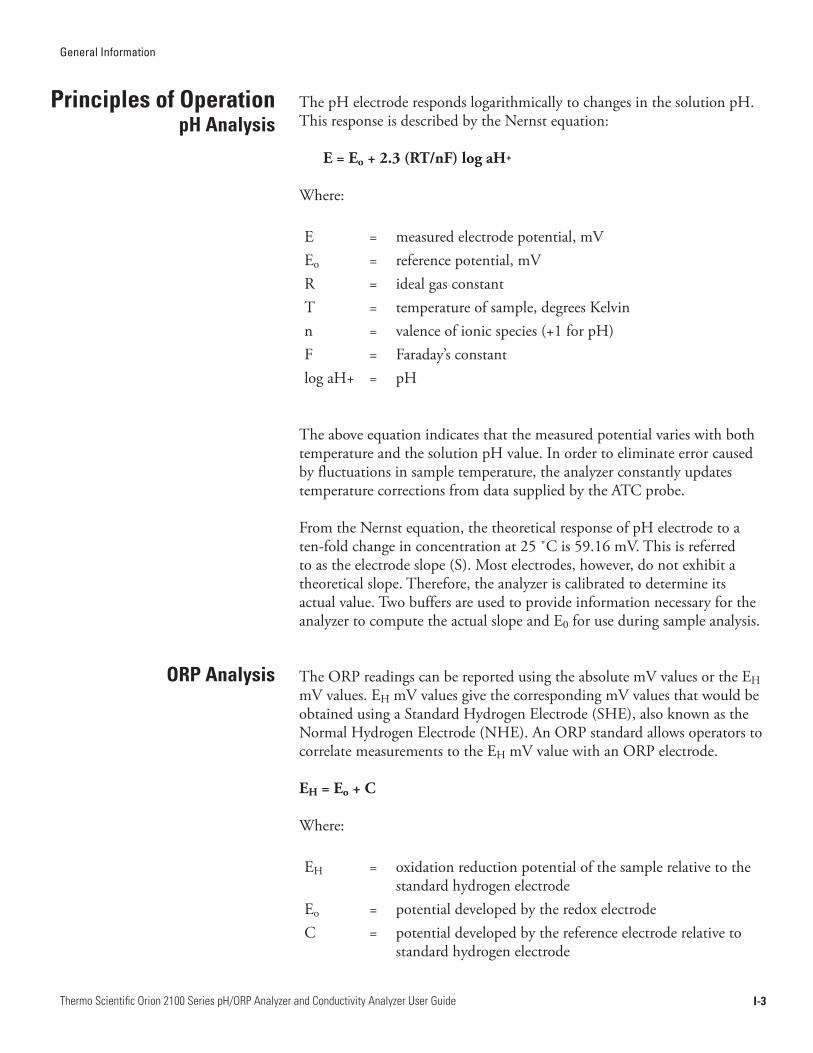
The pH electrode responds logarithmically to changes in the solution pH. This response is described by the Nernst equation:
E=Eo+2.3(RT/nF)logaH+
Where:
E = measured electrode potential, mV Eo = reference potential, mV R = ideal gas constant T = temperature of sample, degrees Kelvin n = valence of ionic species (+1 for pH) F = Faraday’s constant log aH+ = pH
The above equation indicates that the measured potential varies with both temperature and the solution pH value. In order to eliminate error caused by fluctuations in sample temperature, the analyzer constantly updates temperature corrections from data supplied by the ATC probe.
From the Nernst equation, the theoretical response of pH electrode to a ten-fold change in concentration at 25 ˚C is 59.16 mV. This is referred to as the electrode slope (S). Most electrodes, however, do not exhibit a theoretical slope. Therefore, the analyzer is calibrated to determine its actual value. Two buffers are used to provide information necessary for the analyzer to compute the actual slope and E0 for use during sample analysis.
The ORP readings can be reported using the absolute mV values or the EH mV values. EH mV values give the corresponding mV values that would be obtained using a Standard Hydrogen Electrode (SHE), also known as the Normal Hydrogen Electrode (NHE). An ORP standard allows operators to correlate measurements to the EH mV value with an ORP electrode.
EH=Eo+C
Where:
EH = oxidation reduction potential of the sample relative to the standard hydrogen electrode
Eo = potential developed by the redox electrodeC = potential developed by the reference electrode relative to
standard hydrogen electrode
Principles of OperationpH Analysis
ORP Analysis

General Information
I-4Thermo Scientific Orion 2100 Series pH/ORP Analyzer and Conductivity Analyzer User Guide
A conductivity probe is formed by two square electrodes spaced a certain distance apart. The cell constant (K) is defined as the ratio of the distance between the electrodes (d) to the electrode area (A). However, the fringe-field effect (AR) alters the electrode area, therefore K = d / (A + AR). It is normally impossible to measure the fringe-field effect, so the actual cell constant of a conductivity probe is calculated using a standard solution with a known conductivity value. Calibration is essential since the cell constant can vary as much as 10% from the nominal cell constant and the actual cell constant may change over time. Calibration frequency depends on the type of conductivity probe and the application. The most common methods of calibration are automatic or direct calibration.
An automatic calibration is performed by entering the nominal cell constant in the analyzer, immersing the conductivity probe in a conductivity standard and initiating the calibration. When the reading stabilizes, the analyzer displays the calibration standard value at 25 °C. Once the calibration is accepted, the analyzer calculates and displays the actual cell constant.
A direct calibration is performed by immersing the conductivity probe in a calibration standard and then entering the conductivity standard value at the measured temperature so the correct cell constant value is displayed. A direct calibration requires a chart of the calibration standard values at different temperatures or the calibration can be performed with the calibration standard at 25 °C.
A manual calibration is performed by immersing the conductivity probe in a calibration standard and then entering the cell constant value so the correct conductivity standard value at the measured temperature is displayed. A manual calibration requires a chart of the calibration standard values at different temperatures or the calibration can be performed with the calibration standard at 25 °C.
Conductivity Analysis
General Information
I-5Thermo Scientific Orion 2100 Series pH/ORP Analyzer and Conductivity Analyzer User Guide
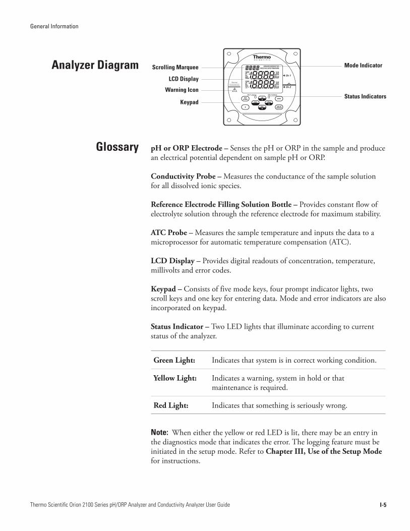
Analyzer Diagram Scrolling Marquee
LCD Display
Warning Icon
Mode Indicator
KeypadStatus Indicators
t Ch 1
t Ch 2
Ch 1 status Ch 2 status
pHorORPElectrode–Senses the pH or ORP in the sample and produce an electrical potential dependent on sample pH or ORP.
ConductivityProbe–Measures the conductance of the sample solution for all dissolved ionic species.
ReferenceElectrodeFillingSolutionBottle–Provides constant flow of electrolyte solution through the reference electrode for maximum stability.
ATCProbe–Measures the sample temperature and inputs the data to a microprocessor for automatic temperature compensation (ATC).
LCDDisplay–Provides digital readouts of concentration, temperature, millivolts and error codes.
Keypad–Consists of five mode keys, four prompt indicator lights, two scroll keys and one key for entering data. Mode and error indicators are also incorporated on keypad.
StatusIndicator–Two LED lights that illuminate according to current status of the analyzer.
GreenLight: Indicates that system is in correct working condition.
YellowLight: Indicates a warning, system in hold or that maintenance is required.
RedLight: Indicates that something is seriously wrong.
Note: When either the yellow or red LED is lit, there may be an entry in the diagnostics mode that indicates the error. The logging feature must be initiated in the setup mode. Refer to ChapterIII,UseoftheSetupMode for instructions.
Glossary

General Information
I-6Thermo Scientific Orion 2100 Series pH/ORP Analyzer and Conductivity Analyzer User Guide
A pH/ORP module or conductivity module can be added by the operator to the second channel of the Thermo Scientific Orion 2100 series pH/ORP and conductivity analyzers for the ultimate flexibility in measurement capabilities. The 2100 series pH/ORP and conductivity analyzers provide accurate and reliable measurements in ultra pure water as well as the harshest industrial environments. Combined with decades of superior Thermo Scientific Orion sensor technology, our systems provide rapid results with complete stability.
Cat. No. Description
2100PH2 Second channel module for pH/ORP
2100CD2 Second channel module for conductivity
When a pH/ORP module or conductivity module is installed on the second channel of a 2100 series pH/ORP or conductivity analyzer, refer to the Thermo Scientific Orion 2100 Series pH/ORP Analyzer and Conductivity Analyzer User Guide for detailed instructions on operating the pH/ORP or conductivity analyzer. Visit www.thermo.com/processwater to download any of the 2100 series analyzer user guides.
Two Channel Analyzer Configurations

II-1Thermo Scientific Orion 2100 Series pH/ORP Analyzer and Conductivity Analyzer User Guide
Chapter II Analyzer Preparation
Thermo Scientific Orion analyzers are assembled, tested and packaged with great care. Refer to Figure II-1.
Report any obvious damage of shipping container to carrier and hold for inspection. The carrier (not Thermo Fisher Scientific) is responsible for any damage incurred during shipment.
1. Open the outer box. If the analyzer is purchased as a kit, the electrodes and accessories that are included with the kit will be in this box.
2. Open the inner box. This box should contain the analyzer, the options kit, user guide CD and appropriate literature.
3. Carefully place the analyzer at a convenient location until proper installation can be completed.
Unpacking the Analyzer
Figure II-1 Unpacking the Analyzer
Analyzer Preparation
II-2Thermo Scientific Orion 2100 Series pH/ORP Analyzer and Conductivity Analyzer User Guide
Refer to the Appendix, Mounting Dimensions section.
Warning: Do not connect power prior to the mounting and plumbing of the analyzer.
• Select a site for the analyzer that allows it to be permanently bolted. Be sure that there is ready access to the electronic controls and electrodes.
• The analyzer location must permit connection to an AC power supply and any connections for output devices.
• The electrodes/probes should be mounted as close to the sampling point as possible. This ensures the fastest possible response to a changing sample condition. Refer to the Appendix, Sample Conditions section.
1. Carefully lift the analyzer and bolt it into place, using either the pipe mounting kit or the sample panel mounting kit.
The system can also be mounted using the standard mounting plate.
Additional information is listed in the Appendix, Specifications section.
Flow rate – 50 to 100 mL/minute.
Pressure – 8 to 100 psig, consult Technical Support for details on sample handling if pressure is outside range.
Temperature – The temperature range is sensor dependent.
Mounting and Plumbing Instructions
Recommendations
Instructions
Sample Requirements

Analyzer Preparation
II-3Thermo Scientific Orion 2100 Series pH/ORP Analyzer and Conductivity Analyzer User Guide
The warning icon highlights important information that should be strictly followed when using the analyzer for your own safety. Failure to follow these instructions may result in injuries.
Warning: Read and observe the following safety recommendations.
• Prior to wiring, a switch or circuit breaker for disconnecting the analyzer from power supply should be installed.
• The switch should be in close proximity to the analyzer and with easy reach of the user.
• The switch should be marked as the disconnecting device for the analyzer.
• To reduce the risk of shock hazard, disconnect the power prior to opening the analyzer.
• Before connecting the analyzer to the main, make sure that the voltage lies within either range: 85-132V, 200 mA or 170-264V, 100 mA; 50-60 Hz AC.
• Cutting off the power by disconnecting power source will not reset the analyzer. This analyzer incorporates a non-volatile memory and will maintain calibration and settings after power failure. Battery power is supplied to the display for the date and time functions.
• If a repair is required, or to arrange Return Material Authorization, call Technical Support or contact your local authorized dealer.
• Installation and wiring of the analyzer may only be carried out in accordance with applicable local and national codes per this user guide.
• Be sure to observe the technical specifications and input ratings.
Electrical Wiring
Safety Requirements

Analyzer Preparation
II-4Thermo Scientific Orion 2100 Series pH/ORP Analyzer and Conductivity Analyzer User Guide
Warning Labels and Locations
Warning: The following section provides important information that should be strictly followed when using the analyzer for your own safety. Failure to follow these instructions may result in injuries.
The safety warning icons are used in two locations on the analyzer.
• Faceplate – Refer to Figure II-2.
• Power supply – Refer to Figure II-3.
Note: Replace the fuse only with a fuse of same rating.
Ch 1 status Ch 2 status
t Ch 1
t Ch 2
Figure II-2 Faceplate
Fuse Holder Fuse
Fuse
Power Supply Fuse Type 115V 250V, 200mA Fast Acting
230V 250V, 100mA Fast Acting
170 - 264V 100mA
85 - 132V 200mA
NEUTRAL
Ground
Input PowerFigure II-3
Power Supply
Analyzer Preparation
II-5Thermo Scientific Orion 2100 Series pH/ORP Analyzer and Conductivity Analyzer User Guide
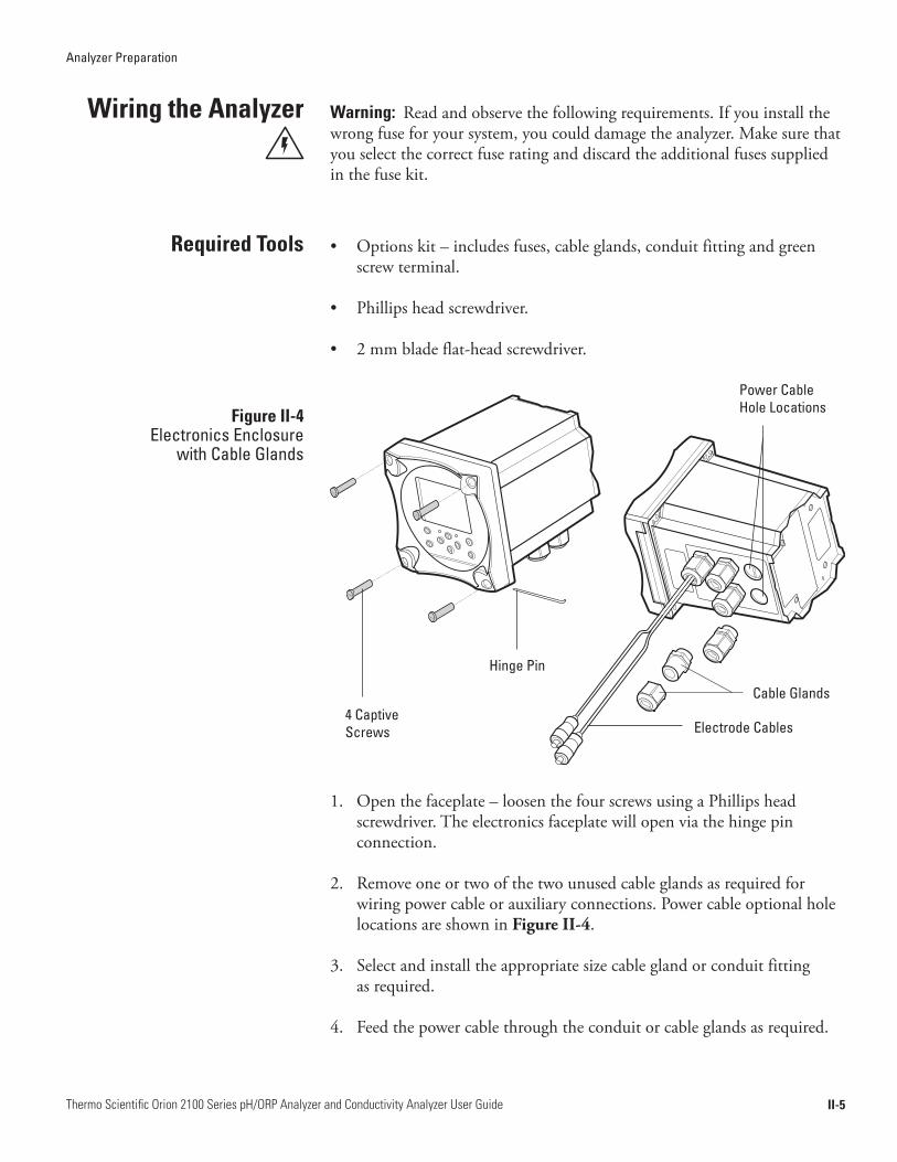
Wiring the Analyzer Warning: Read and observe the following requirements. If you install the wrong fuse for your system, you could damage the analyzer. Make sure that you select the correct fuse rating and discard the additional fuses supplied in the fuse kit.
• Options kit – includes fuses, cable glands, conduit fitting and green screw terminal.
• Phillips head screwdriver.
• 2 mm blade flat-head screwdriver.
1. Open the faceplate – loosen the four screws using a Phillips head screwdriver. The electronics faceplate will open via the hinge pin connection.
2. Remove one or two of the two unused cable glands as required for wiring power cable or auxiliary connections. Power cable optional hole locations are shown in Figure II-4.
3. Select and install the appropriate size cable gland or conduit fitting as required.
4. Feed the power cable through the conduit or cable glands as required.
Figure II-4 Electronics Enclosure
with Cable Glands
4 CaptiveScrews
Hinge Pin
Power Cable Hole Locations
Cable Glands
Electrode Cables
Required Tools

Analyzer Preparation
II-6Thermo Scientific Orion 2100 Series pH/ORP Analyzer and Conductivity Analyzer User Guide
5. Wire the power cable to the green screw terminal connector from the options kit. Select correct terminal for hot conductor depending on line voltage. Refer to Figure II-5 for terminal connector location.
6. Plug the terminal connector into the power supply. Refer to Figure II-3.
7. Select the correct fuse from the fuse kit. Install by inserting the fuse in the fuse holder and secure it using the twist and lock method. The fuses are clearly labeled with the appropriate voltages for your system. Refer to Figure II-3. Refer to the table below for fuse selection.
AC Voltage Fuse Rating
115V 200mA, 250V, Fast Acting
230V 100mA, 250V Fast Acting
Figure II-5 Terminal Connector Location
Terminal Connector

Analyzer Preparation
II-7Thermo Scientific Orion 2100 Series pH/ORP Analyzer and Conductivity Analyzer User Guide
Terminal Layout Terminal Layout Terminal Layout Terminal Layout
1 Sout (mA) sensing signal
9 Relay 1 26 Sensing electrode
28 Do not connect
2 GND common ground
10 Relay 1 27 Do not connect
29 Do not connect
3 Tout (mA) temp. signal
11 Relay 2 30 Preamp power
4 Air pump (ISE only)
12 Relay 2 31 Preamp ground
5 Air pump (ISE only)
13 Relay 3 32 Shield
6 Shield ground for conductivity
14 Relay 3 33 Shield
7 Do not connect 15 Do not connect 34 Jumper to pin 26 when using preamp
8 Do not connect 16 Temperature ground
17 Temperature drive
18 Temperature sense
19 Solution ground
20 Conductivity drive +
21 Conductivity sense +
22 Conductivity sense -
23 Conductivity drive -
24 Reference electrode
25 Jumper to pin 24 when using preamp
Terminal Assignments
2726
21 43 65 87 2928 3130 3332 34
109 1211 1413 16 1817 2019 2221 2423 2515
Figure II-6 Terminal Assignments
Analyzer Preparation
II-8Thermo Scientific Orion 2100 Series pH/ORP Analyzer and Conductivity Analyzer User Guide
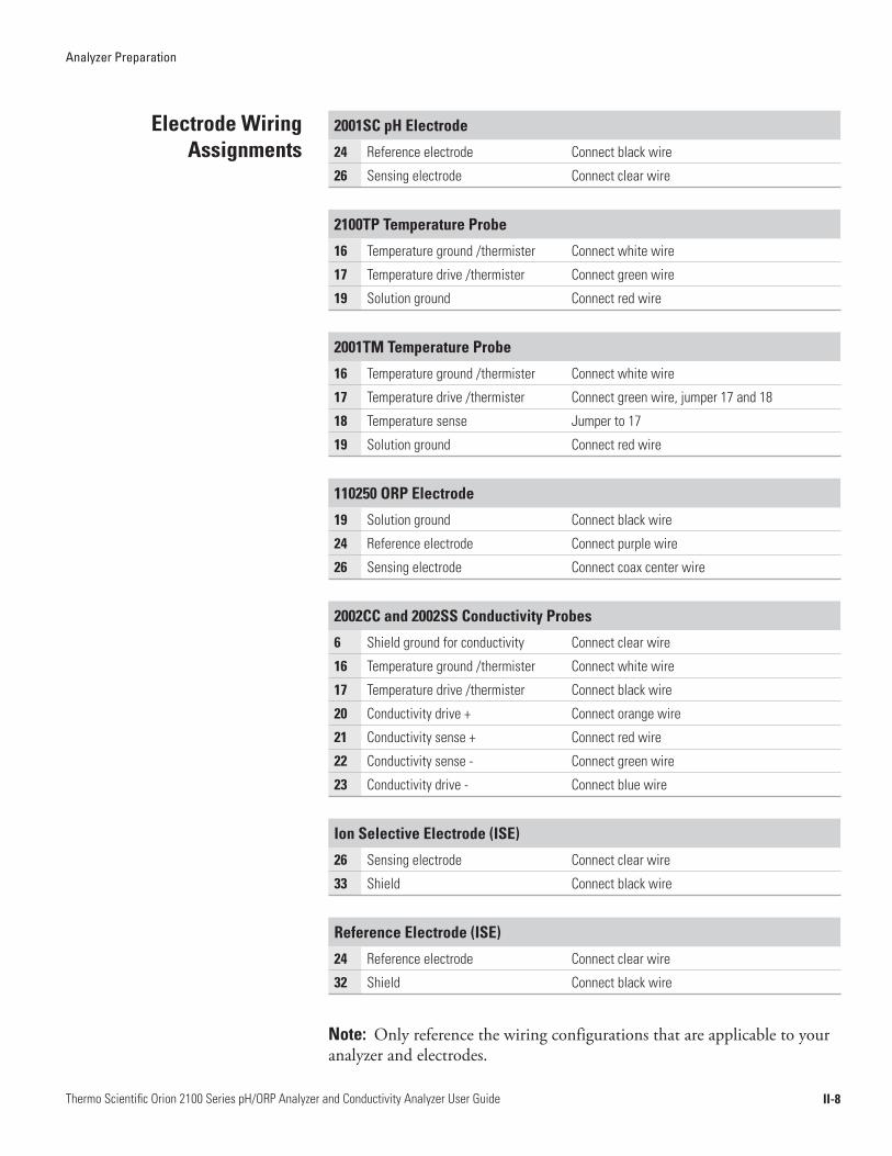
Electrode Wiring Assignments
2001SC pH Electrode
24 Reference electrode Connect black wire
26 Sensing electrode Connect clear wire
2100TP Temperature Probe
16 Temperature ground /thermister Connect white wire
17 Temperature drive /thermister Connect green wire
19 Solution ground Connect red wire
2001TM Temperature Probe
16 Temperature ground /thermister Connect white wire
17 Temperature drive /thermister Connect green wire, jumper 17 and 18
18 Temperature sense Jumper to 17
19 Solution ground Connect red wire
110250 ORP Electrode
19 Solution ground Connect black wire
24 Reference electrode Connect purple wire
26 Sensing electrode Connect coax center wire
2002CC and 2002SS Conductivity Probes
6 Shield ground for conductivity Connect clear wire
16 Temperature ground /thermister Connect white wire
17 Temperature drive /thermister Connect black wire
20 Conductivity drive + Connect orange wire
21 Conductivity sense + Connect red wire
22 Conductivity sense - Connect green wire
23 Conductivity drive - Connect blue wire
Ion Selective Electrode (ISE)
26 Sensing electrode Connect clear wire
33 Shield Connect black wire
Reference Electrode (ISE)
24 Reference electrode Connect clear wire
32 Shield Connect black wire
Note: Only reference the wiring configurations that are applicable to your analyzer and electrodes.
Analyzer Preparation
II-9Thermo Scientific Orion 2100 Series pH/ORP Analyzer and Conductivity Analyzer User Guide
1. Unpack the electrode cable.
2. Feed the tinned wire through a cable gland assembly with the holes (2 or 1).
3. Follow the terminal assignments shown in Figure II-6 for the proper electrode cable wiring location.
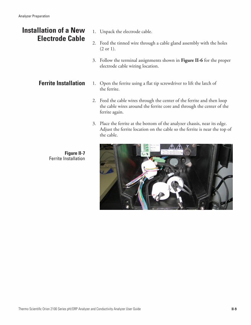
1. Open the ferrite using a flat tip screwdriver to lift the latch of the ferrite.
2. Feed the cable wires through the center of the ferrite and then loop the cable wires around the ferrite core and through the center of the ferrite again.
3. Place the ferrite at the bottom of the analyzer chassis, near its edge. Adjust the ferrite location on the cable so the ferrite is near the top of the cable.
Installation of a New Electrode Cable
Ferrite Installation
Figure II-7 Ferrite Installation
Analyzer Preparation
II-10Thermo Scientific Orion 2100 Series pH/ORP Analyzer and Conductivity Analyzer User Guide
1. Unpack the ROSS® 2001SC pH electrode and carefully remove it from the storage cap. The pH electrode must be used in conjunction with the automatic temperature compensation (ATC) probe (Cat. No. 2100TM).
2. Prepare the electrode according to the instruction sheet or manual that is packaged with the electrode.
3. Plug the electrode cable into the top of the electrode. Be sure to push back black cap to verify a secure connection between male and female pin connection prior to tightening.
4. Tighten screw cap connection to cable.
Note: Do not twist the cable while tightening the connection. Twisting may cause damage requiring premature replacement of the cable.
1. Install the automatic temperature compensation (ATC) probe (Cat. No. 2100TM) to the correct terminal for temperature.
Installation of an ATC Probe
Installation of a New pH Electrode

Analyzer Preparation
II-11Thermo Scientific Orion 2100 Series pH/ORP Analyzer and Conductivity Analyzer User Guide
1. Unpack the ORP electrode and carefully remove it from the storage cap. The ORP electrode must be used in conjunction with the automatic temperature compensation (ATC) probe (Cat. No. 2100TM).
2. Prepare the electrode according to the instruction sheet or manual that is packaged with the electrode.
3. Plug the electrode cable into the top of the electrode. Be sure to push back black cap to verify a secure connection between male and female pin connection prior to tightening.
4. Tighten screw cap connection to cable.
Note: Do not twist the cable while tightening the connection. Twisting may cause damage requiring premature replacement of the cable.
Installation of a New ORP Electrode
Analyzer Preparation
II-12Thermo Scientific Orion 2100 Series pH/ORP Analyzer and Conductivity Analyzer User Guide
1. Unpack the conductivity probe from the shipping box.
2. Prepare the probe according to the instruction sheet or manual that is packaged with the electrode.
3. Plug the electrode cable into the top of the probe. Be sure to push back black cap to verify a secure connection between male and female pin connection prior to tightening.
4. Tighten screw cap connection to cable.
Note: Do not twist the cable while tightening the connection. Twisting may cause damage requiring premature replacement of the cable.
Installation of a New Conductivity Probe
III-1Thermo Scientific Orion 2100 Series pH/ORP Analyzer and Conductivity Analyzer User Guide
Chapter III Analyzer Operation
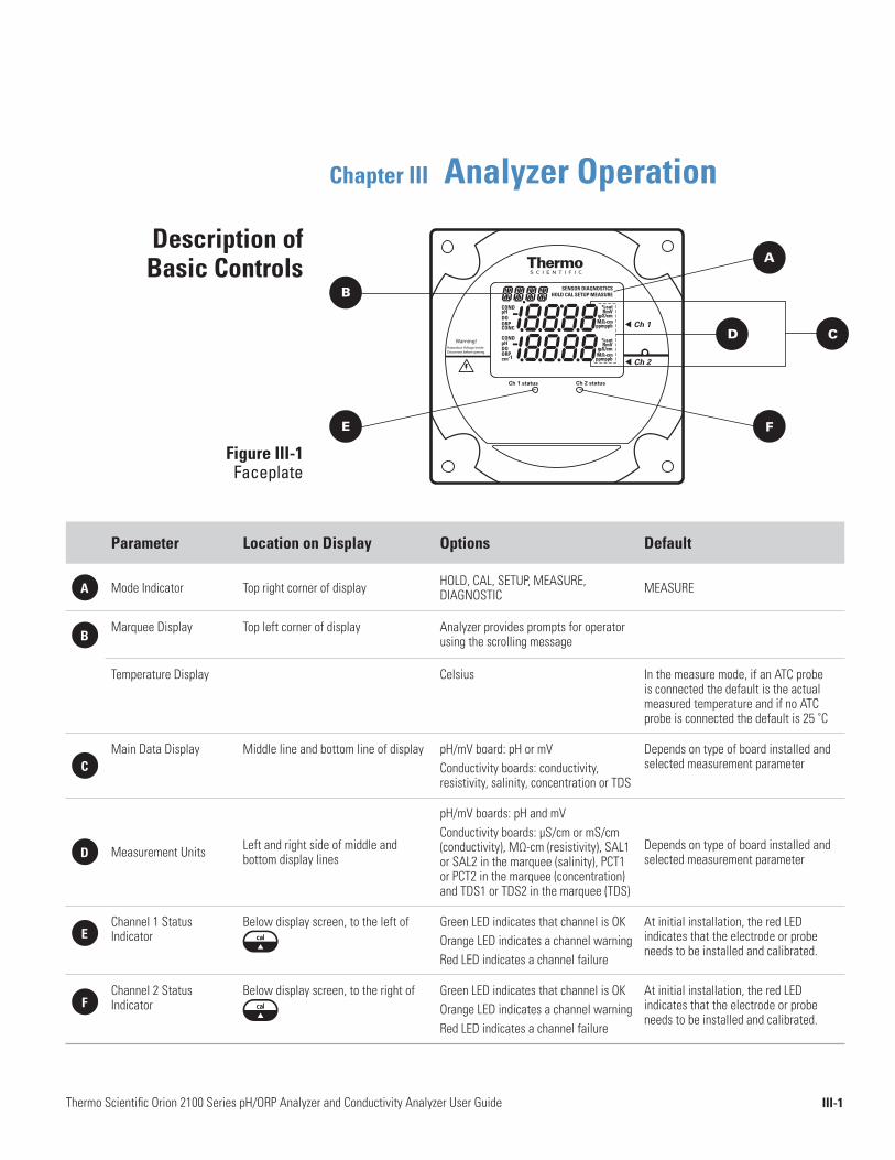
Description of Basic Controls
Figure III-1 Faceplate
Ch 1 status Ch 2 status
t Ch 1
t Ch 2
B
A
C D
F E
Parameter Location on Display Options Default
A Mode Indicator Top right corner of display HOLD, CAL, SETUP, MEASURE, DIAGNOSTIC MEASURE
BMarquee Display Top left corner of display Analyzer provides prompts for operator
using the scrolling message
Temperature Display Celsius In the measure mode, if an ATC probe is connected the default is the actual measured temperature and if no ATC probe is connected the default is 25 ˚C
CMain Data Display Middle line and bottom line of display pH/mV board: pH or mV
Conductivity boards: conductivity, resistivity, salinity, concentration or TDS
Depends on type of board installed and selected measurement parameter
D Measurement Units Left and right side of middle and bottom display lines
pH/mV boards: pH and mVConductivity boards: µS/cm or mS/cm (conductivity), MΩ-cm (resistivity), SAL1 or SAL2 in the marquee (salinity), PCT1 or PCT2 in the marquee (concentration) and TDS1 or TDS2 in the marquee (TDS)
Depends on type of board installed and selected measurement parameter
EChannel 1 Status Indicator
Below display screen, to the left of Green LED indicates that channel is OKOrange LED indicates a channel warningRed LED indicates a channel failure
At initial installation, the red LED indicates that the electrode or probe needs to be installed and calibrated.
FChannel 2 Status Indicator
Below display screen, to the right of Green LED indicates that channel is OKOrange LED indicates a channel warningRed LED indicates a channel failure
At initial installation, the red LED indicates that the electrode or probe needs to be installed and calibrated.
Analyzer Operation
III-2Thermo Scientific Orion 2100 Series pH/ORP Analyzer and Conductivity Analyzer User Guide
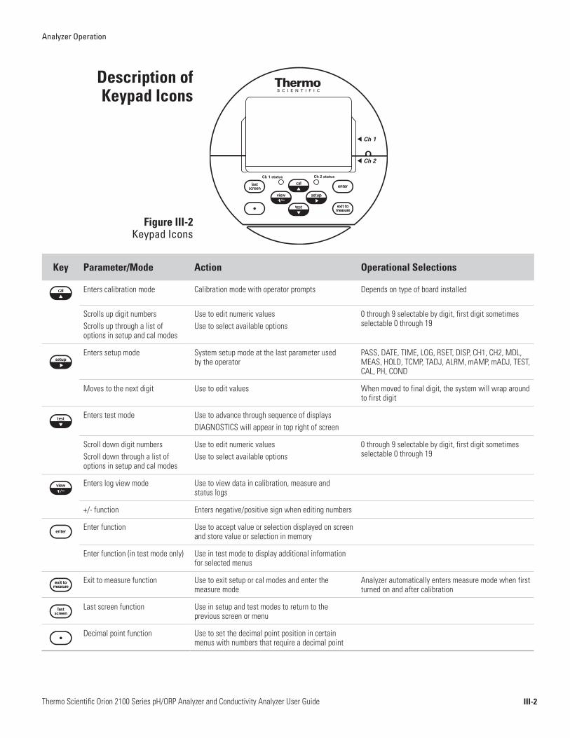
Key Parameter/Mode Action Operational Selections
Enters calibration mode Calibration mode with operator prompts Depends on type of board installed
Scrolls up digit numbersScrolls up through a list of options in setup and cal modes
Use to edit numeric valuesUse to select available options
0 through 9 selectable by digit, first digit sometimes selectable 0 through 19
Enters setup mode System setup mode at the last parameter used by the operator
PASS, DATE, TIME, LOG, RSET, DISP, CH1, CH2, MDL, MEAS, HOLD, TCMP, TADJ, ALRM, mAMP, mADJ, TEST, CAL, PH, COND
Moves to the next digit Use to edit values When moved to final digit, the system will wrap around to first digit
Enters test mode Use to advance through sequence of displaysDIAGNOSTICS will appear in top right of screen
Scroll down digit numbersScroll down through a list of options in setup and cal modes
Use to edit numeric valuesUse to select available options
0 through 9 selectable by digit, first digit sometimes selectable 0 through 19
Enters log view mode Use to view data in calibration, measure and status logs
+/- function Enters negative/positive sign when editing numbers
Enter function Use to accept value or selection displayed on screen and store value or selection in memory
Enter function (in test mode only) Use in test mode to display additional information for selected menus
Exit to measure function Use to exit setup or cal modes and enter the measure mode
Analyzer automatically enters measure mode when first turned on and after calibration
Last screen function Use in setup and test modes to return to the previous screen or menu
Decimal point function Use to set the decimal point position in certain menus with numbers that require a decimal point
Description of Keypad Icons
Figure III-2 Keypad Icons
Ch 1 status Ch 2 status
t Ch 1
t Ch 2
Analyzer Operation
III-3Thermo Scientific Orion 2100 Series pH/ORP Analyzer and Conductivity Analyzer User Guide
Before the first sample measurements can be taken, the setup mode should be programmed and a successful calibration must be performed by the operator and stored in the memory of the analyzer.
• Press to enter the setup mode.• SETUP appears in the mode indicator screen.• HOLD is displayed while in the setup mode.• The analyzer will enter the setup mode at the last menu that was
used by the operator.
• Press and to loop through the menu options.
• Press to select the desired menu option and set the menu option parameters.
• Press and to:• Scroll between On and OFF for the selected menu option. • Scroll and set the first digit value to 0 through 19.• Scroll and set the remaining digit values to 0 through 9.
• Press to move to the next digit (scroll right) to set each digit value (4 digits maximum).
• Press to save the entered parameter for the selected menu option.
• Press to exit the current screen and return to the previous screen.
• Press to exit the setup mode and return to the measure mode. If is pressed, will not return the operator to the setup mode.
The operator must reenter the setup mode by pressing .
If a single channel analyzer is in use, all of the menu options are accessible by pressing / in the setup mode. The system will loop through the menu options and all of the menu options are in the same level of the setup mode.
If a two channel analyzer is in use, only the general menu options are accessible by pressing / in the setup mode. The channel 1 and channel 2 specific menu options must be accessed by selecting the CH1 or CH2 menu options in the setup mode. The channel specific menu options are in the second level in setup mode. If a two channel analyzer is in use, make sure to program both the channel 1 and channel 2 menu options in the setup mode.
Use of the Setup Mode
Navigating Tips for the Setup Mode
Channel Specific Menu Options in the Setup Mode
Analyzer Operation
III-4Thermo Scientific Orion 2100 Series pH/ORP Analyzer and Conductivity Analyzer User Guide
The default password is 0000 – indicates password protection has not been activated.
System password: Management secured password protection of setup mode and calibration process.
Calibration password: Operator secured password for protection of calibration process only.
If password(s) are activated:
• System prompts operator to enter system password:• Marquee: ENTER PASSWORD• Main display top: PASS• Main display bottom: 0000 (flashing)
• Correct password – Allows operator to enter setup mode for custom programming options.
• Incorrect password – Password incorrect or not entered correctly.• System password:
• Marquee: SYSTEM PASS INCORRECT• Main display: E035
• Calibration password:• Marquee: CAL PASS INCORRECT• Main display: E034
• Verify password and re-enter it.
If password(s) are de-activated:
• System enters the setup mode at the last setup menu option used by the operator. • Marquee: Flashes current menu option• Main display: SEL SCrn
Using Password Protection

Analyzer Operation
III-5Thermo Scientific Orion 2100 Series pH/ORP Analyzer and Conductivity Analyzer User Guide
The setup mode features programmable menu options. The order of the menu options is dependent on the direction the operator scrolls by pressing
or . The menu options are listed below by pressing .
The following menu options are displayed in the main setup mode of one and two channel analyzers.
Set either of two password options:• System password – Setup settings protected, accessed by authorized
operators only• Calibration password – Calibration menu data is protected, accessed by
authorized operators only• Default password is 0000 – Disables both passwords• Forgot your password? Contact Technical Support at 1-800-225-1480
Set the date in US or Europe format:• Enter month, day and year• Default date – System will continue to keep date and time due to
battery back up, operator must set in accordance to local time zone• If the battery is removed, the system will show 01/01/2000
Set the time:• Enter hour and minutes in 24 hour format• Default time – System will continue to keep date and time due to
battery back up, operator must set in accordance to local time zone• If the battery is removed the system will show 00:01
Set the data logging interval for measure log (calibration and error logs are accessed in the test mode):• Set the log interval as hour:minute• Default log interval is 00:00 – logging disabled• Minimum log interval is 1 minute, maximum log interval is 99 hours
and 59 minutes
Setup Mode Overview
PASS
DATE
TIME
LOG
General Setup Mode Menu Options
Analyzer Operation
III-6Thermo Scientific Orion 2100 Series pH/ORP Analyzer and Conductivity Analyzer User Guide
Reset the analyzer to factory defaults for setup parameters:• Use to troubleshoot the system (a hard reset can be performed if the
keypad and software are not responding, refer to Chapter VI, Resetting the Analyzer)
Warning: Resetting the analyzer will lose all stored information including relay, logs and calibration settings.
Set the automatic lighting options for the backlit display:• AUtO – Brightness will change in response to ambient light source• On – Backlit display is always on• OFF – Backlit display is always off• Default display – AUtO
RSET
DISP
Analyzer Operation
III-7Thermo Scientific Orion 2100 Series pH/ORP Analyzer and Conductivity Analyzer User Guide
Channel Specific Setup Mode Menu Options
MDLfor pH/ORP
MDLfor conductivity
If a two channel analyzer is in use, the following menu options are specific to the channel that is selected by the operator. The operator must select the channel number in the main setup mode (CH1 or CH2) and the menu options that are relative to the measurement capability of that channel will be displayed. If a one channel analyzer is being used, the CH1 and CH2 menus will not be shown.
Set the parameter that will be displayed in the measure mode:• pH/ORP – Select pH or ORP (mV) as the measurement parameter
Set the parameter that will be displayed in the measure mode:• Conductivity – Select conductivity, resistivity, salinity, concentration or
TDS as the measurement parameter• If concentration is selected as the measurement parameter, select NaCl,
HCl, NaOH, H2SO4 or NO3 as the concentration setting• If total dissolved solids (TDS) is selected as the measurement parameter,
set the TDS factor from 0.00 to 10.00 mg/L
Set the mV display option, decimal places displayed when in the pH measure mode and the isopotential point used when in the pH measure mode (menu available only for analyzers with a pH/ORP board installed): • Enable mV values to be displayed on the second line • Scroll between On or OFF • Default mV setting – OFF• Set the number of decimal places displayed in the pH measure mode • Scroll between 1 or 2 decimal places • Default decimal places – 2• Set the pH filter algorithm • Scroll between Stnd (standard) or UP (ultrapure) • Default pH filter type – Stnd• Set the pH isopontential point • Enter the pH isopontential point value • Default pH isopontential point – 7.00
MEASfor pH
CH1 or CH2

Analyzer Operation
III-8Thermo Scientific Orion 2100 Series pH/ORP Analyzer and Conductivity Analyzer User Guide
Set the mV display option (menu available only for analyzers with a pH/ORP board installed): • Enable mV values to be displayed on the second line• Scroll between On or OFF• Default mV setting – OFF
Set the time that the system will remain on hold before the actual measurements are displayed after a calibration:• Once the hold time expires, the system implements any programmed
changes to settings in the setup mode• After a calibration, the hold function allows the operator to rinse the
electrodes prior to recording actual measurement values• Default hold time – 5 minutes
Set the temperature compensation parameters for pH/ORP (menu option available for analyzers with a pH/ORP board installed):• Enable or disable the ATC probe measurements • Scroll between On or OFF • Default setting – On• If the ATC probe measurements are disabled, manually set the solution
temperature value • Set the solution temperature from -10.0 °C to 110.0 °C• Set the solution temperature compensation type • Scroll through OFF, t (treated), UP (ultrapure) and USr (operator
entered value) • The treated solution temperature compensation value is
-0.032 pH units per degree Celsius • The ultrapure solution temperature compensation value is
-0.016 pH units per degree Celsius • The operator defined solution temperature compensation value can
be set from -0.999 to 0.999 pH units per degree Celsius
HOLD
MEASfor ORP
TCMPfor pH/ORP

Analyzer Operation
III-9Thermo Scientific Orion 2100 Series pH/ORP Analyzer and Conductivity Analyzer User Guide
TADJ
TCMPfor conductivity
Set the temperature compensation parameters for conductivity (menu option available for analyzers with a conductivity board installed):• Set the temperature compensation type • Scroll through OFF, LIn (linear), nLF (nonlinear for natural
waters), nACL (NaCl for ultrapure water with traces of sodium chloride), HCL (HCl for ultrapure water with traces of hydrochloric acid) and nH3 (NH3 for ultrapure water with traces of ammonia)
• Set the linear temperature compensation value if LIn was selected as the temperature compensation type
• The operator defined linear temperature compensation value can be set from 0.00 to 10.00 percent per degree Celsius
Adjust the temperature reading from the ATC probe by ± 5.0 ˚C:• Default adjustment – 0.0 degrees C
Set up to three alarms – high, low and an error signaling contact:• Relays 1 and 2 (rLY1, rLY2) are normally open dry contacts used to set
high and low alarms for measurement values • rLY1 and rLY2 options – OFF, HI, LO• Relay 3 (rLY3) is normally a closed contact that can be dedicated to
errors (will close if power to analyzer is lost), this alarm is influenced by calibration, errors and offline or hold status
• rLY3 options – OFF, CAL, HOLD, Err• Default setting for all alarms – OFF
ALRM
Analyzer Operation
III-10Thermo Scientific Orion 2100 Series pH/ORP Analyzer and Conductivity Analyzer User Guide
Set the two analog current outputs (SOUt and tOUt):• Scroll between 4-20 mA or 0-20 mA current signals • The outputs share a common return, but are isolated from the main
circuitry of the analyzer • Default output current – 4-20 mA• Scroll between logarithmic (LOg) and linear (LIn) scale for SOUt• Set the low and high limits for the sensor output (SOUt) • Default for pH – 4 (low) and 10 (high) • Default for ORP – 0 mV (low) and 600 mV (high) • Default for conductivity – 1 µS/cm (low) and 100 µS/cm (high) • Default for resistivity – 1 MΩ-cm (low) and 10 MΩ-cm (high) • Default for salinity – 1 (low) and 35 (high) • Default for concentration – 1 (low) and 9 (high) • Default for TDS – 10 (low) and 100 (high)• Set the low and high limits for the temperature output (tOUt)
Set the mA offset adjustment value for the sensor (SOUt) and temperature (tOUt) outputs:• Select the sensor (SOUt) or temperature (tOUt) output• Scroll the numeric offset value and positive or negative offset value• Default mA offset – 00.0 mA
Test relays and analog output lines (DIAGNOSTICS will appear in the mode indicator):• Method to activate/deactivate relays and outputs to be tested• Verify the accuracy of the analog outputs when used with an external
loop calibrator• Provides the values and settings for the mA output and relays• mA output • 4-20 or 0-20 • The sensor (SOUt) and temperature (tOUt) low and high values• Relay status • Set RLY1, RLY2 and RLY3 status to OFF or On
mAMP
mADJ
TEST
Analyzer Operation
III-11Thermo Scientific Orion 2100 Series pH/ORP Analyzer and Conductivity Analyzer User Guide
Set calibration frequency in hours:• High limit is 19999 hours• Low limit is 00000 hours• Default setting – 720 hours
Select the buffer set that will be used for automatic buffer recognition during a pH calibration:• US – pH 1.68, 4.01, 7.00, 10.01, 12.46 buffers• EUrO – pH 1.68, 4.01, 6.86, 9.18 buffers• Default buffer set – US
Set the nominal cell constant value of the conductivity probe for automatic cell constant adjustment during a conductivity calibration: • Set the value from 0.001 cm-1 to 199.9 cm-1
• The Thermo Scientific Orion 2002CC conductivity probe has a nominal cell constant of 0.475 cm-1 and the Thermo Scientific Orion 2002SS conductivity probe has a nominal cell constant of 0.1 cm-1.
• Default nominal cell constant value – 0.100 cm-1
CAL
PHfor pH/ORP
CONDfor conductivity
Analyzer Operation
III-12Thermo Scientific Orion 2100 Series pH/ORP Analyzer and Conductivity Analyzer User Guide
Default Operator Action Scrolling Marquee Main Display Notes
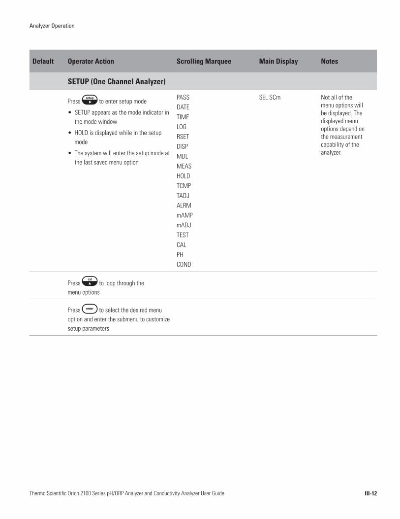
SETUP (One Channel Analyzer)
Press to enter setup mode
• SETUP appears as the mode indicator in the mode window
• HOLD is displayed while in the setup mode
• The system will enter the setup mode at the last saved menu option
PASSDATETIMELOGRSETDISP MDLMEASHOLDTCMPTADJALRMmAMPmADJTESTCALPHCOND
SEL SCrn Not all of the menu options will be displayed. The displayed menu options depend on the measurement capability of the analyzer.
Press to loop through the menu options
Press to select the desired menu option and enter the submenu to customize setup parameters
Analyzer Operation
III-13Thermo Scientific Orion 2100 Series pH/ORP Analyzer and Conductivity Analyzer User Guide
Default Operator Action Scrolling Marquee Main Display Notes
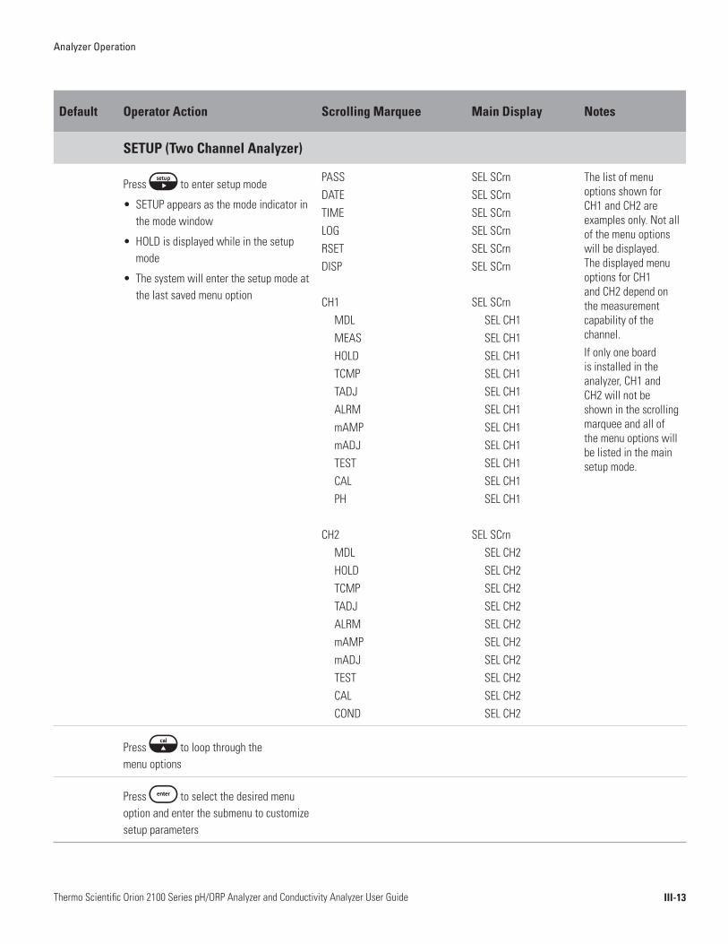
SETUP (Two Channel Analyzer)
Press to enter setup mode
• SETUP appears as the mode indicator in the mode window
• HOLD is displayed while in the setup mode
• The system will enter the setup mode at the last saved menu option
PASSDATETIMELOGRSETDISP
CH1MDLMEASHOLDTCMPTADJALRMmAMPmADJTESTCALPH
CH2MDLHOLDTCMPTADJALRMmAMPmADJTESTCALCOND
SEL SCrnSEL SCrnSEL SCrnSEL SCrnSEL SCrnSEL SCrn
SEL SCrnSEL CH1SEL CH1SEL CH1SEL CH1SEL CH1SEL CH1SEL CH1SEL CH1SEL CH1SEL CH1SEL CH1
SEL SCrnSEL CH2SEL CH2SEL CH2SEL CH2SEL CH2SEL CH2SEL CH2 SEL CH2 SEL CH2 SEL CH2
The list of menu options shown for CH1 and CH2 are examples only. Not all of the menu options will be displayed. The displayed menu options for CH1 and CH2 depend on the measurement capability of the channel.If only one board is installed in the analyzer, CH1 and CH2 will not be shown in the scrolling marquee and all of the menu options will be listed in the main setup mode.
Press to loop through the menu options
Press to select the desired menu option and enter the submenu to customize setup parameters
Analyzer Operation
III-14Thermo Scientific Orion 2100 Series pH/ORP Analyzer and Conductivity Analyzer User Guide
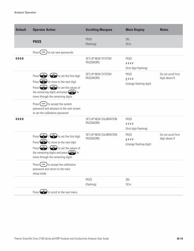
Default Operator Action Scrolling Marquee Main Display Notes
PASSPASS (flashing)
SEL SCrn
Press to set new passwords
0 0 0 0 SET-UP NEW SYSTEM PASSWORD
PASS# # # #(first digit flashing)
Press / to set the first digit
Press to move to the next digit
Press / to set the values of the remaining digits and press to move through the remaining digits
SET-UP NEW SYSTEM PASSWORD
PASS# # # #(change flashing digit)
Do not scroll first digit above 9
Press to accept the system password and advance to the next screen to set the calibration password
0 0 0 0 SET-UP NEW CALIBRATION PASSWORD
PASS# # # #(first digit flashing)
Press / to set the first digit
Press to move to the next digit
Press / to set the values of the remaining digits and press to move through the remaining digits
SET-UP NEW CALIBRATION PASSWORD
PASS# # # #(change flashing digit)
Do not scroll first digit above 9
Press to accept the calibration password and return to the main setup mode
PASS (flashing)
SELSCrn
Press to scroll to the next menu
Analyzer Operation
III-15Thermo Scientific Orion 2100 Series pH/ORP Analyzer and Conductivity Analyzer User Guide
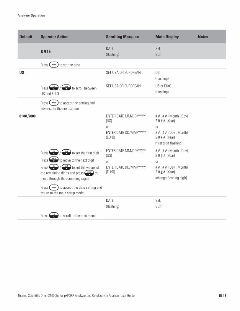
Default Operator Action Scrolling Marquee Main Display Notes
DATEDATE (flashing)
SELSCrn
Press to set the date
US SET USA OR EUROPEAN US(flashing)
Press / to scroll between US and EUrO
SET USA OR EUROPEAN US or EUrO(flashing)
Press to accept the setting and advance to the next screen
01/01/2000 ENTER DATE MM/DD/YYYY (US) orENTER DATE DD/MM/YYYY (EUrO)
# # . # # (Month . Day) 2 0 # # (Year) or# # . # # (Day . Month) 2 0 # # (Year)(first digit flashing)
Press / to set the first digit
Press to move to the next digit
Press / to set the values of the remaining digits and press to move through the remaining digits
ENTER DATE MM/DD/YYYY (US) orENTER DATE DD/MM/YYYY (EUrO)
# # . # # (Month . Day) 2 0 # # (Year)or# # . # # (Day . Month) 2 0 # # (Year)(change flashing digit)
Press to accept the date setting and return to the main setup mode
DATE (flashing)
SELSCrn
Press to scroll to the next menu

Analyzer Operation
III-16Thermo Scientific Orion 2100 Series pH/ORP Analyzer and Conductivity Analyzer User Guide
Default Operator Action Scrolling Marquee Main Display Notes
TIMETIME (flashing)
SELSCrn
Press to set the time
00:01 ENTER 24HR TIME HOUR/MINUTE
# # : # # (hour : minute)(first digit flashing)
Press / to set the first digit
Press to move to the next digit
Press / to set the values of the remaining digits and press to move through the remaining digits
ENTER 24HR TIME HOUR/MINUTE
# # : # # (hour : minute)(change flashing digit)
Set in 24 hour time format
Press to accept the time setting and return to the main setup mode
TIME (flashing)
SELSCrn
Press to scroll to the next menu
Analyzer Operation
III-17Thermo Scientific Orion 2100 Series pH/ORP Analyzer and Conductivity Analyzer User Guide
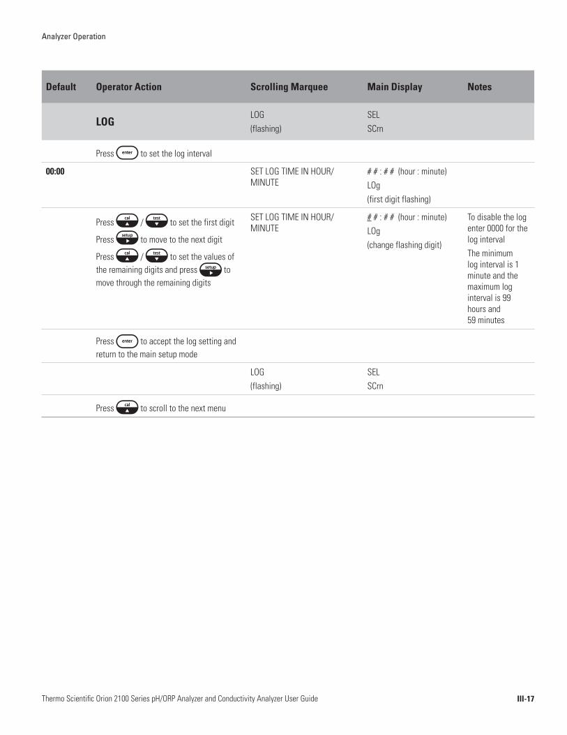
Default Operator Action Scrolling Marquee Main Display Notes
LOGLOG (flashing)
SELSCrn
Press to set the log interval
00:00 SET LOG TIME IN HOUR/MINUTE
# # : # # (hour : minute)LOg(first digit flashing)
Press / to set the first digit
Press to move to the next digit
Press / to set the values of the remaining digits and press to move through the remaining digits
SET LOG TIME IN HOUR/MINUTE
# # : # # (hour : minute)LOg(change flashing digit)
To disable the log enter 0000 for the log interval The minimum log interval is 1 minute and the maximum log interval is 99 hours and 59 minutes
Press to accept the log setting and return to the main setup mode
LOG(flashing)
SELSCrn
Press to scroll to the next menu

Analyzer Operation
III-18Thermo Scientific Orion 2100 Series pH/ORP Analyzer and Conductivity Analyzer User Guide
Warning: The reset command will erase all operator settings, logs and calibration data. The analyzer will need to be set up and calibrated again before it can resume operation.
Default Operator Action Scrolling Marquee Main Display Notes
RSETRSET (flashing)
SELSCrn
Press to reset the analyzer
PUSH TEST VIEW ENTER TO RESET
rSEt?
To Reset the Analyzer:
Press
Press
Press
When the reset is complete, the system will return to the measure mode. The operator will need to re-enter the setup mode to continue programming the setup parameters. Press to return to the setup mode.
PUSH TEST VIEW ENTER TO RESET
rSEt?
This command resets all previously set parameters to factory default values. Use this command only to set the analyzer to original factory setup values.
To Abort the Reset:
Press to return to the main setup mode
PRESS TEST VIEW ENTER TO RESET
rSEt?
RSET (flashing)
SELSCrn
Press to scroll to the next menu
Warning: Resetting the analyzer will erase all stored information including relay, logs and calibration settings.
Analyzer Operation
III-19Thermo Scientific Orion 2100 Series pH/ORP Analyzer and Conductivity Analyzer User Guide
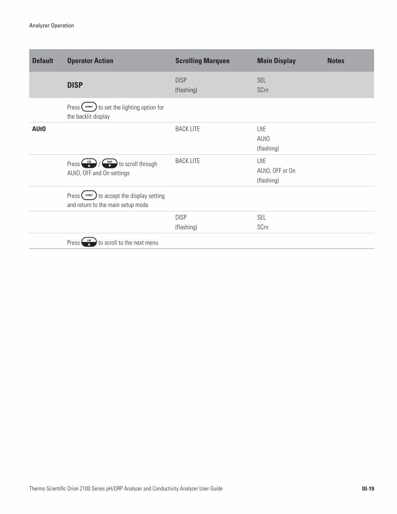
Default Operator Action Scrolling Marquee Main Display Notes
DISPDISP (flashing)
SELSCrn
Press to set the lighting option for the backlit display
AUtO BACK LITE LItEAUtO (flashing)
Press / to scroll through AUtO, OFF and On settings
BACK LITE LItEAUtO, OFF or On(flashing)
Press to accept the display setting and return to the main setup mode
DISP (flashing)
SELSCrn
Press to scroll to the next menu
Analyzer Operation
III-20Thermo Scientific Orion 2100 Series pH/ORP Analyzer and Conductivity Analyzer User Guide
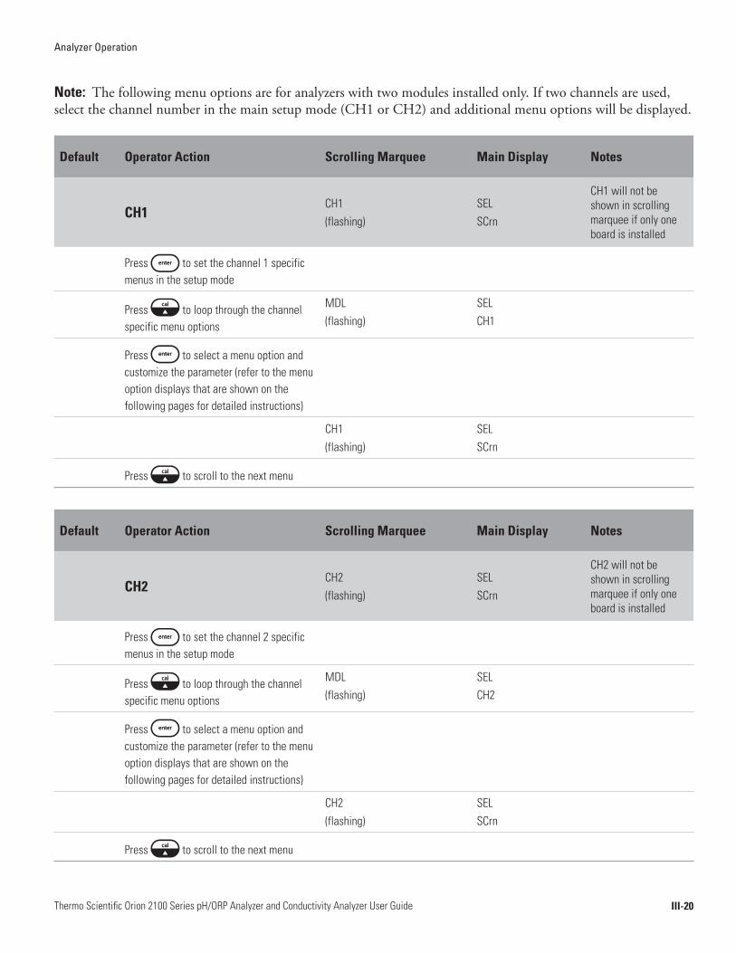
Note: The following menu options are for analyzers with two modules installed only. If two channels are used, select the channel number in the main setup mode (CH1 or CH2) and additional menu options will be displayed.
Default Operator Action Scrolling Marquee Main Display Notes
CH1CH1(flashing)
SELSCrn
CH1 will not be shown in scrolling marquee if only one board is installed
Press to set the channel 1 specific menus in the setup mode
Press to loop through the channel specific menu options
MDL(flashing)
SELCH1
Press to select a menu option and customize the parameter (refer to the menu option displays that are shown on the following pages for detailed instructions)
CH1(flashing)
SELSCrn
Press to scroll to the next menu
Default Operator Action Scrolling Marquee Main Display Notes
CH2CH2(flashing)
SELSCrn
CH2 will not be shown in scrolling marquee if only one board is installed
Press to set the channel 2 specific menus in the setup mode
Press to loop through the channel specific menu options
MDL(flashing)
SELCH2
Press to select a menu option and customize the parameter (refer to the menu option displays that are shown on the following pages for detailed instructions)
CH2(flashing)
SELSCrn
Press to scroll to the next menu

Analyzer Operation
III-21Thermo Scientific Orion 2100 Series pH/ORP Analyzer and Conductivity Analyzer User Guide
Note: The following menu option is for analyzers with a pH/ORP module installed only.
Default Operator Action Scrolling Marquee Main Display Notes
MDL MDL (flashing)
SELSCrn
SEL CH1 or SEL CH2 on main display of two channel analyzer
Press to set the measurement parameter for the analyzer
PH SELECT PH OR ORP PH(flashing)
Press / to scroll between PH and OrP and select the desired measurement parameter
SELECT PH OR ORP PH or OrP(flashing)
Press to accept the measurement setting and return to the main setup mode
CH1 or CH2(flashing)
SELSCrn
Displayed for two channel analyzer
Press to return to the channel specific menu options in the setup mode
Action required for two channel analyzer
MDL (flashing)
SELSCrn
SEL CH1 or SEL CH2 on main display of two channel analyzer
Press to scroll to the next menu
Analyzer Operation
III-22Thermo Scientific Orion 2100 Series pH/ORP Analyzer and Conductivity Analyzer User Guide
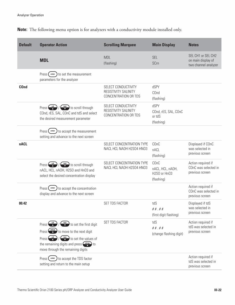
Note: The following menu option is for analyzers with a conductivity module installed only.
Default Operator Action Scrolling Marquee Main Display Notes
MDL MDL (flashing)
SELSCrn
SEL CH1 or SEL CH2 on main display of two channel analyzer
Press to set the measurement parameters for the analyzer
COnd SELECT CONDUCTIVITY RESISTIVITY SALINITY CONCENTRATION OR TDS
dSPYCOnd(flashing)
Press / to scroll through COnd, rES, SAL, COnC and tdS and select the desired measurement parameter
SELECT CONDUCTIVITY RESISTIVITY SALINITY CONCENTRATION OR TDS
dSPYCOnd, rES, SAL, COnC or tdS(flashing)
Press to accept the measurement setting and advance to the next screen
nACL SELECT CONCENTRATION TYPE NACL HCL NAOH H2SO4 HNO3
COnCnACL(flashing)
Displayed if COnC was selected in previous screen
Press / to scroll through nACL, HCL, nAOH, H2SO and HnO3 and select the desired concentration display
SELECT CONCENTRATION TYPE NACL HCL NAOH H2SO4 HNO3
COnCnACL, HCL, nAOH, H2SO or HnO3(flashing)
Action required if COnC was selected in previous screen
Press to accept the concentration display and advance to the next screen
Action required if COnC was selected in previous screen
00.42 SET TDS FACTOR tdS# # . # #(first digit flashing)
Displayed if tdS was selected in previous screen
Press / to set the first digit
Press to move to the next digit
Press / to set the values of the remaining digits and press to move through the remaining digits
SET TDS FACTOR tdS# # . # #(change flashing digit)
Action required if tdS was selected in previous screen
Press to accept the TDS factor setting and return to the main setup
Action required if tdS was selected in previous screen

Analyzer Operation
III-23Thermo Scientific Orion 2100 Series pH/ORP Analyzer and Conductivity Analyzer User Guide
Default Operator Action Scrolling Marquee Main Display Notes
MDL (cont’d)
CH1 or CH2(flashing)
SELSCrn
Displayed for two channel analyzer
Press to return to the channel specific menu options in the setup mode
Action required for two channel analyzer
MDL (flashing)
SELSCrn
SEL CH1 or SEL CH2 on main display of two channel analyzer
Press to scroll to the next menu

Analyzer Operation
III-24Thermo Scientific Orion 2100 Series pH/ORP Analyzer and Conductivity Analyzer User Guide
Note: The following menu option is for analyzers with a pH/ORP module installed only.
Default Operator Action Scrolling Marquee Main Display Notes
MEAS MEAS (flashing)
SELSCrn
SEL CH1 or SEL CH2 on main display of two channel analyzer
Press to set measure parameters
OFF SHOW MV ON SINGLE CHANNEL DISPLAY
OFF (flashing)
Press / to scroll between OFF and On
SHOW MV ON SINGLE CHANNEL DISPLAY
OFF or On(flashing)
Press to accept the setting and advance to the next screen
2 SELECT RESOLUTION 1 OR 2 DECIMAL POINTS
rES2(flashing)
Press / to scroll between 2 and 1 decimal point options
SELECT RESOLUTION 1 OR 2 DECIMAL POINTS
rES2 or 1(flashing)
Press to accept the setting and advance to the next screen
Stnd SELECT FILTER ALGORITHM STANDARD OR ULTRAPURE WATER
Stnd(flashing)
Press / to scroll between Stnd and UP filter algorithm options
SELECT FILTER ALGORITHM STANDARD OR ULTRAPURE WATER
Stnd or UP(flashing)
Press to accept the setting and advance to the next screen
07.00 SET ISO POINT # # . # #(first digit flashing)
Press / to set the first digit
Press to move to the next digit
Press / to set the values of the remaining digits and press to move through the remaining digits
SET ISO POINT # # . # #(change flashing digit)
Press to accept the setting and return to the main setup mode
Analyzer Operation
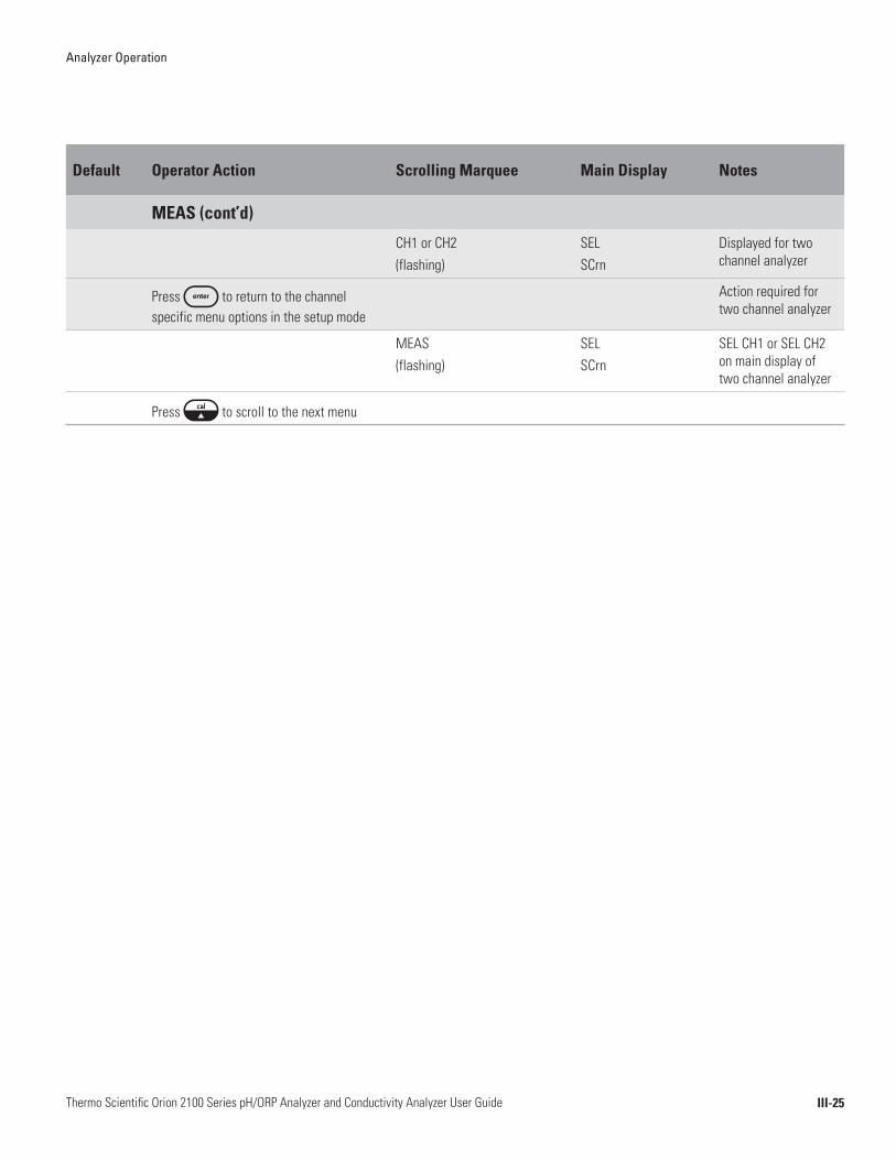
III-25Thermo Scientific Orion 2100 Series pH/ORP Analyzer and Conductivity Analyzer User Guide
Default Operator Action Scrolling Marquee Main Display Notes
MEAS (cont’d)
CH1 or CH2(flashing)
SELSCrn
Displayed for two channel analyzer
Press to return to the channel specific menu options in the setup mode
Action required for two channel analyzer
MEAS (flashing)
SELSCrn
SEL CH1 or SEL CH2 on main display of two channel analyzer
Press to scroll to the next menu

Analyzer Operation
III-26Thermo Scientific Orion 2100 Series pH/ORP Analyzer and Conductivity Analyzer User Guide
Default Operator Action Scrolling Marquee Main Display Notes
HOLDHOLD (flashing)
SELSCrn
SEL CH1 or SEL CH2 on main display of two channel analyzer
Press to set the hold time
00:05 ENTER HOLD TIME HOUR/MINUTE
# # : # # (first digit flashing)
Press / to set the first digit
Press to move to the next digit
Press / to set the values of the remaining digits and press to move through the remaining digits
ENTER HOLD TIME HOUR/MINUTE
# # : # # (change flashing digit)
Press to accept the setting and advance to the next screen
LASt ENTER HOLD STATE LAST OR USER VALUE
LASt(flashing)
Press / to scroll between LASt and USEr
ENTER HOLD STATE LAST OR USER VALUE
LASt or USEr(flashing)
Press to accept the setting and advance to the next screen
21.0 ENTER FIXED USER VALUE IN mA
# # . # (first digit flashing)
Displayed if USEr was selected in previous screen
Press / to set the first digit
Press to move to the next digit
Press / to set the values of the remaining digits and press to move through the remaining digits
ENTER FIXED USER VALUE IN mA
# # . # (change flashing digit)
Action required if USEr was selected in previous screen
Press to accept the setting and advance to the next screen
Action required if USEr was selected in previous screen
OFF HOLD TO 22mA WHEN ERROR OFF(flashing)
Press / to scroll between OFF and On
HOLD TO 22mA WHEN ERROR OFF or On(flashing)
Analyzer Operation
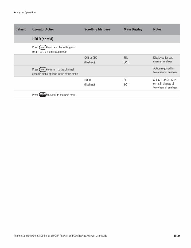
III-27Thermo Scientific Orion 2100 Series pH/ORP Analyzer and Conductivity Analyzer User Guide
Default Operator Action Scrolling Marquee Main Display Notes
HOLD (cont’d)
Press to accept the setting and return to the main setup mode
CH1 or CH2(flashing)
SELSCrn
Displayed for two channel analyzer
Press to return to the channel specific menu options in the setup mode
Action required for two channel analyzer
HOLD (flashing)
SELSCrn
SEL CH1 or SEL CH2 on main display of two channel analyzer
Press to scroll to the next menu
Analyzer Operation
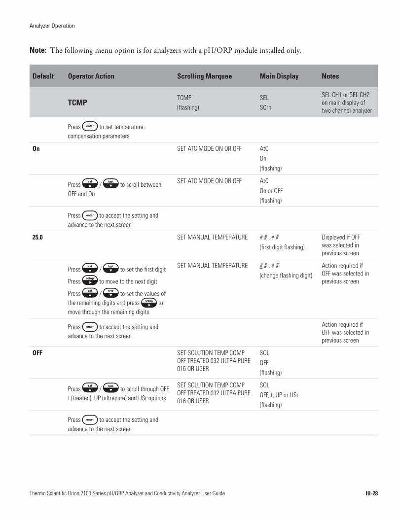
III-28Thermo Scientific Orion 2100 Series pH/ORP Analyzer and Conductivity Analyzer User Guide
Note: The following menu option is for analyzers with a pH/ORP module installed only.
Default Operator Action Scrolling Marquee Main Display Notes
TCMP TCMP (flashing)
SELSCrn
SEL CH1 or SEL CH2 on main display of two channel analyzer
Press to set temperature compensation parameters
On SET ATC MODE ON OR OFF AtCOn (flashing)
Press / to scroll between OFF and On
SET ATC MODE ON OR OFF AtCOn or OFF(flashing)
Press to accept the setting and advance to the next screen
25.0 SET MANUAL TEMPERATURE # # . # #(first digit flashing)
Displayed if OFF was selected in previous screen
Press / to set the first digit
Press to move to the next digit
Press / to set the values of the remaining digits and press to move through the remaining digits
SET MANUAL TEMPERATURE # # . # #(change flashing digit)
Action required if OFF was selected in previous screen
Press to accept the setting and advance to the next screen
Action required if OFF was selected in previous screen
OFF SET SOLUTION TEMP COMP OFF TREATED 032 ULTRA PURE 016 OR USER
SOLOFF(flashing)
Press / to scroll through OFF, t (treated), UP (ultrapure) and USr options
SET SOLUTION TEMP COMP OFF TREATED 032 ULTRA PURE 016 OR USER
SOLOFF, t, UP or USr(flashing)
Press to accept the setting and advance to the next screen

Analyzer Operation
III-29Thermo Scientific Orion 2100 Series pH/ORP Analyzer and Conductivity Analyzer User Guide
Default Operator Action Scrolling Marquee Main Display Notes
TCMP (cont’d)
0.000 SET COMP VALUE PER DEGREE C
# . # # #(first digit flashing)
Displayed if USr was selected in previous screen
Press / to set the first digit
Press to move to the next digit
Press / to set the values of the remaining digits and press to move through the remaining digits
SET COMP VALUE PER DEGREE C
# . # # #(change flashing digit)
Action required if USr was selected in previous screen
Press to accept the setting and return to the main setup mode
CH1 or CH2(flashing)
SELSCrn
Displayed for two channel analyzer
Press to return to the channel specific menu options in the setup mode
Action required for two channel analyzer
TCMP (flashing)
SELSCrn
SEL CH1 or SEL CH2 on main display of two channel analyzer
Press to scroll to the next menu

Analyzer Operation
III-30Thermo Scientific Orion 2100 Series pH/ORP Analyzer and Conductivity Analyzer User Guide
Note: The following menu option is for analyzers with a conductivity module installed only.
Default Operator Action Scrolling Marquee Main Display Notes
TCMP TCMP (flashing)
SELSCrn
SEL CH1 or SEL CH2 on main display of two channel analyzer
Press to set temperature compensation parameters
OFF SET TEMP COMP OFF LIN NLF NACL HCL NH3
tCOFF (flashing)
Press / to scroll through OFF, LIn, nLF, nACL, HCL and nH3
SET TEMP COMP OFF LIN NLF NACL HCL NH3
tCOFF, LIn, nLF, nACL, HCL or nH3(flashing)
Press to accept the setting and return to the main setup mode or advance to the next screen
02.00 SET LIN TEMP COEF tC# # . # #(first digit flashing)
Displayed if LIn was selected in previous screen
Press / to set the first digit
Press to move to the next digit
Press / to set the values of the remaining digits and press to move through the remaining digits
SET LIN TEMP COEF tC# # . # #(change flashing digit)
Action required if LIn was selected in previous screen
Press to accept the setting and return to the main setup mode
CH1 or CH2(flashing)
SELSCrn
Displayed for two channel analyzer
Press to return to the channel specific menu options in the setup mode
Action required for two channel analyzer
TCMP (flashing)
SELSCrn
SEL CH1 or SEL CH2 on main display of two channel analyzer
Press to scroll to the next menu

Analyzer Operation
III-31Thermo Scientific Orion 2100 Series pH/ORP Analyzer and Conductivity Analyzer User Guide
Default Operator Action Scrolling Marquee Main Display Notes
TADJTADJ (flashing)
SELSCrn
SEL CH1 or SEL CH2 on main display of two channel analyzer
Press to set the temperature adjustment value
0.0 C TEMPERATURE ADJUSTMENT AdJ# . # c(first digit flashing)
Press / to set the first digit
Press to move to the next digit
Press / to set the value of the next digit
TEMPERATURE ADJUSTMENT AdJ# . # c(change flashing digit)
The maximum temperature adjustment is ± 5.0 ˚C
Press to set a positive or negative temperature value
TEMPERATURE ADJUSTMENT AdJ- # . # c
Press to accept the setting and return to the main setup mode
CH1 or CH2(flashing)
SELSCrn
Displayed for two channel analyzer
Press to return to the channel specific menu options in the setup mode
Action required for two channel analyzer
TADJ(flashing)
SELSCrn
SEL CH1 or SEL CH2 on main display of two channel analyzer
Press to scroll to the next menu
Analyzer Operation
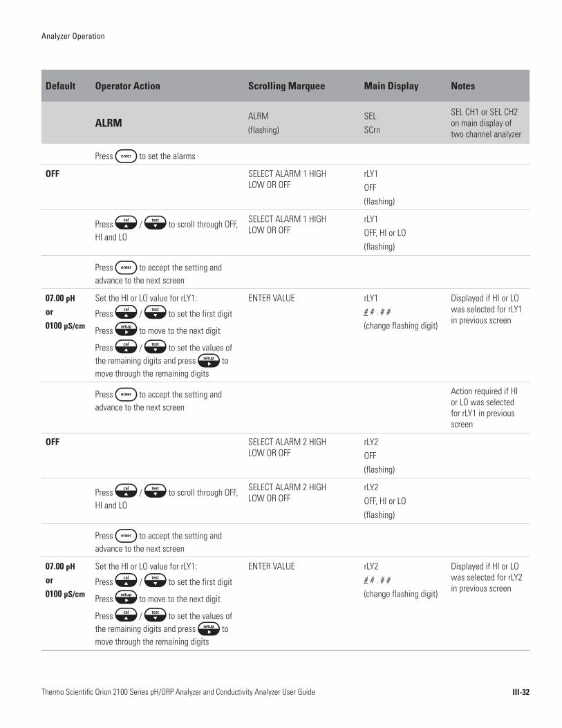
III-32Thermo Scientific Orion 2100 Series pH/ORP Analyzer and Conductivity Analyzer User Guide
Default Operator Action Scrolling Marquee Main Display Notes
ALRMALRM (flashing)
SELSCrn
SEL CH1 or SEL CH2 on main display of two channel analyzer
Press to set the alarms
OFF SELECT ALARM 1 HIGH LOW OR OFF
rLY1OFF(flashing)
Press / to scroll through OFF, HI and LO
SELECT ALARM 1 HIGH LOW OR OFF
rLY1OFF, HI or LO(flashing)
Press to accept the setting and advance to the next screen
07.00 pH
or 0100 µS/cm
Set the HI or LO value for rLY1:
Press / to set the first digit
Press to move to the next digit
Press / to set the values of the remaining digits and press to move through the remaining digits
ENTER VALUE rLY1# # . # #(change flashing digit)
Displayed if HI or LO was selected for rLY1 in previous screen
Press to accept the setting and advance to the next screen
Action required if HI or LO was selected for rLY1 in previous screen
OFF SELECT ALARM 2 HIGH LOW OR OFF
rLY2OFF(flashing)
Press / to scroll through OFF, HI and LO
SELECT ALARM 2 HIGH LOW OR OFF
rLY2OFF, HI or LO(flashing)
Press to accept the setting and advance to the next screen
07.00 pH
or 0100 µS/cm
Set the HI or LO value for rLY1:
Press / to set the first digit
Press to move to the next digit
Press / to set the values of the remaining digits and press to move through the remaining digits
ENTER VALUE rLY2# # . # #(change flashing digit)
Displayed if HI or LO was selected for rLY2 in previous screen
Analyzer Operation
III-33Thermo Scientific Orion 2100 Series pH/ORP Analyzer and Conductivity Analyzer User Guide
Default Operator Action Scrolling Marquee Main Display Notes
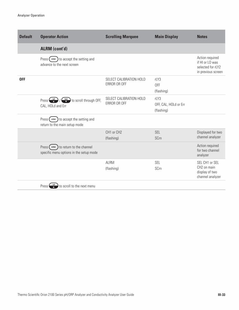
ALRM (cont’d)
Press to accept the setting and advance to the next screen
Action required if HI or LO was selected for rLY2 in previous screen
OFF SELECT CALIBRATION HOLD ERROR OR OFF
rLY3OFF(flashing)
Press / to scroll through OFF, CAL, HOLd and Err
SELECT CALIBRATION HOLD ERROR OR OFF
rLY3OFF, CAL, HOLd or Err(flashing)
Press to accept the setting and return to the main setup mode
CH1 or CH2(flashing)
SELSCrn
Displayed for two channel analyzer
Press to return to the channel specific menu options in the setup mode
Action required for two channel analyzer
ALRM(flashing)
SELSCrn
SEL CH1 or SEL CH2 on main display of two channel analyzer
Press to scroll to the next menu

Analyzer Operation
III-34Thermo Scientific Orion 2100 Series pH/ORP Analyzer and Conductivity Analyzer User Guide
Default Operator Action Scrolling Marquee Main Display Notes
mAMPmAMP (flashing)
SELSCrn
SEL CH1 or SEL CH2 on main display of two channel analyzer
Press to set the analog output
4-20 Press / to scroll between 4-20 and 0-20
SELECT 0-20 OR 4-20 4-20 or 0-20(flashing)
Press to accept the setting and advance to the next screen
LOg Press / to scroll between LOg and LIn
SELECT LOG OR LINEAR OUTPUT
SOUtLOg or LIn(flashing)
Press to accept the setting and advance to the next screen
Measure mode dependent
mA SENSOR OUTPUT LOW VALUE
LO# # # . #(first digit flashing)
Press to move the decimal point
Press / to set the first digit
Press to move to the next digit
Press / to set the values of the remaining digits and press to move through the remaining digits
mA SENSOR OUTPUT LOW VALUE
LO# # #. #(change flashing digit)
Press to accept the setting and advance to the next screen
Measure mode dependent
mA SENSOR OUTPUT HIGH VALUE
HI# # # . #(first digit flashing)
Press to move the decimal point
Press / to set the first digit
Press to move to the next digit
Press / to set the values of the remaining digits and press to move through the remaining digits
mA SENSOR OUTPUT HIGH VALUE
HI# # #. #(change flashing digit)
Press to accept the setting and advance to the next screen

Analyzer Operation
III-35Thermo Scientific Orion 2100 Series pH/ORP Analyzer and Conductivity Analyzer User Guide
Default Operator Action Scrolling Marquee Main Display Notes
mAMP (cont’d)
Press to set the temperature output value
SET TEMP OUTPUT VALUE tOUt
05.0 C mA TEMP OUTPUT LOW VALUE LO# # . # c(first digit flashing)
Press / to set the first digit
Press to move to the next digit
Press / to set the values of the remaining digits and press to move through the remaining digits
Press to set a positive or negative temperature value
mA TEMP OUTPUT LOW VALUE LO# #.# C(change flashing digit)
Press to accept the setting and advance to the next screen
45.0 C mA TEMP OUTPUT HIGH VALUE HI# # . # c(first digit flashing)
Press / to set the first digit
Press to move to the next digit
Press / to set the values of the remaining digits and press to move through the remaining digits
mA TEMP OUTPUT HIGH VALUE HI# # . # c(change flashing digit)
Press to accept the setting and return to the main setup mode
CH1 or CH2(flashing)
SELSCrn
Displayed for two channel analyzer
Press to return to the channel specific menu options in the setup mode
Action required for two channel analyzer
mAMP(flashing)
SELSCrn
SEL CH1 or SEL CH2 on main display of two channel analyzer
Press to scroll to the next menu

Analyzer Operation
III-36Thermo Scientific Orion 2100 Series pH/ORP Analyzer and Conductivity Analyzer User Guide
Default Operator Action Scrolling Marquee Main Display Notes
mADJmADJ (flashing)
SELSCrn
SEL CH1 or SEL CH2 on main display of two channel analyzer
Press to set the sensor and temperature mA offset values
SELECT TEMP OR SENSOR OUTPUT
SOUt or tOUt(flashing)
Press / to scroll between SOUt or tOUt and select SOUt
SELECT TEMP OR SENSOR OUTPUT
SOUt(flashing)
Press to accept the setting and advance to the next screen
0.00 SENSOR 4-20mA OUTPUT ADJUSTMENT
AdJ0 . 0 #(last flashing digit)
Press / to set the sensor mA offset value
Press to set a positive or negative sensor mA offset
SENSOR 4-20mA OUTPUT ADJUSTMENT
AdJ0 . 0 #(change flashing digit)
Press to accept the setting and return to the main setup mode
CH1 or CH2(flashing)
SELSCrn
Displayed for two channel analyzer
Press to return to the channel specific menu options in the setup mode
Action required for two channel analyzer
mADJ(flashing)
SELSCrn
SEL CH1 or SEL CH2 on main display of two channel analyzer
Press to set the sensor and temperature mA offset values
SELECT TEMP OR SENSOR OUTPUT
SOUt or tOUt(flashing)
Press / to scroll between SOUt or tOUt and select tOUt
SELECT TEMP OR SENSOR OUTPUT
tOUt(flashing)
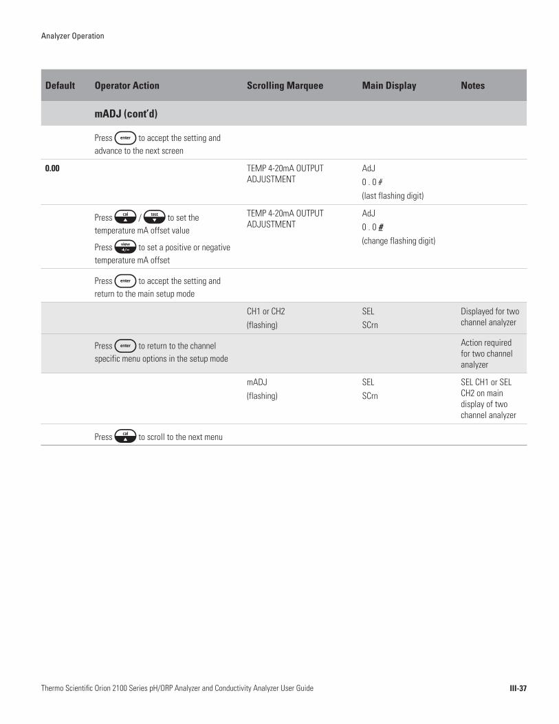
Analyzer Operation
III-37Thermo Scientific Orion 2100 Series pH/ORP Analyzer and Conductivity Analyzer User Guide
Default Operator Action Scrolling Marquee Main Display Notes
mADJ (cont’d)
Press to accept the setting and advance to the next screen
0.00 TEMP 4-20mA OUTPUT ADJUSTMENT
AdJ0 . 0 #(last flashing digit)
Press / to set the temperature mA offset value
Press to set a positive or negative temperature mA offset
TEMP 4-20mA OUTPUT ADJUSTMENT
AdJ0 . 0 #(change flashing digit)
Press to accept the setting and return to the main setup mode
CH1 or CH2(flashing)
SELSCrn
Displayed for two channel analyzer
Press to return to the channel specific menu options in the setup mode
Action required for two channel analyzer
mADJ(flashing)
SELSCrn
SEL CH1 or SEL CH2 on main display of two channel analyzer
Press to scroll to the next menu

Analyzer Operation
III-38Thermo Scientific Orion 2100 Series pH/ORP Analyzer and Conductivity Analyzer User Guide
Default Operator Action Scrolling Marquee Main Display Notes
TEST TEST (flashing)
SELSCrn
SEL CH1 or SEL CH2 on main display of two channel analyzer
Press to test the mAmp outputs (4-20) and relays (rLY)
DIAGNOSTICS appears above SETUP in mode window
To Test tOUt:
4-20 Press / to scroll between 4-20 and rLY settings and select 4-20
SELECT mA OR RELAY tESt4 - 20(flashing)
Press to test 4-20 outputs
SELECT TEMP OR SENSOR OUTPUT
4 - 20tOUt or SOUt(flashing)
Press / to scroll between SOUt and tOUt settings and select tOUt
SELECT TEMP OR SENSOR OUTPUT
4 - 20tOUt(flashing)
Press to display the tOUt low value
Actual low value displayed
mA TEMP OUTPUT LOW VALUE LO# . # c
4.0 mA are sourced at output terminal 11
Press to display the tOUt high value
Actual high value displayed
mA TEMP OUTPUT HIGH VALUE HI# . # c
20 mA are sourced at output terminal 11
Press to accept the test and return to the main setup mode
CH1 or CH2(flashing)
SELSCrn
Display for two channel analyzer only
Press to return to the channel specific menu options in the setup mode
Action for two channel analyzer only
TEST (flashing)
SELSCrn
SEL CH1 or SEL CH2 on main display of two channel analyzer
Press to test the mA outputs (4-20) and relays (rLY)
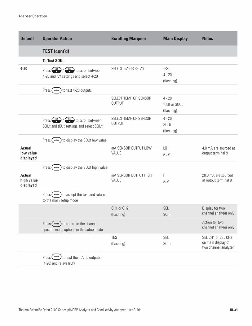
Analyzer Operation
III-39Thermo Scientific Orion 2100 Series pH/ORP Analyzer and Conductivity Analyzer User Guide
Default Operator Action Scrolling Marquee Main Display Notes
TEST (cont’d)
To Test SOUt:
4-20 Press / to scroll between 4-20 and rLY settings and select 4-20
SELECT mA OR RELAY tESt4 - 20(flashing)
Press to test 4-20 outputs
SELECT TEMP OR SENSOR OUTPUT
4 - 20tOUt or SOUt(flashing)
Press / to scroll between SOUt and tOUt settings and select SOUt
SELECT TEMP OR SENSOR OUTPUT
4 - 20SOUt(flashing)
Press to display the SOUt low value
Actual low value displayed
mA SENSOR OUTPUT LOW VALUE
LO# . #
4.0 mA are sourced at output terminal 9
Press to display the SOUt high value
Actual high value displayed
mA SENSOR OUTPUT HIGH VALUE
HI#. #
20.0 mA are sourced at output terminal 9
Press to accept the test and return to the main setup mode
CH1 or CH2(flashing)
SELSCrn
Display for two channel analyzer only
Press to return to the channel specific menu options in the setup mode
Action for two channel analyzer only
TEST (flashing)
SELSCrn
SEL CH1 or SEL CH2 on main display of two channel analyzer
Press to test the mAmp outputs (4-20) and relays (rLY)

Analyzer Operation
III-40Thermo Scientific Orion 2100 Series pH/ORP Analyzer and Conductivity Analyzer User Guide
Default Operator Action Scrolling Marquee Main Display Notes
TEST (cont’d)
To Test rLY:
4-20 Press / to scroll between 4-20 and rLY settings and select rLY
SELECT mA OR RELAY tEStrLY(flashing)
Press to test relay outputs
Actual rLY1 status
Press / to set the rLY1 setting OFF or On
USE ARROWS TO TOGGLE RELAY 1
rLY1OFF or On
Relay contact according to screen indication
Press to accept the rLY1 test and move to the rLY2 test
Actual rLY2 status
Press / to set the rLY2 setting OFF or On
USE ARROWS TO TOGGLE RELAY 2
rLY2OFF or On
Relay contact according to screen indication
Press to accept the rLY2 test and move to the rLY3 test
Actual rLY3 status
Press / to set the rLY3 setting OFF or On
USE ARROWS TO TOGGLE RELAY 3
rLY3OFF or On
Relay contact according to screen indication
Press to accept the rLY3 test and return to the main setup mode
CH1 or CH2(flashing)
SELSCrn
Display for two channel analyzer only
Press to return to the channel specific menu options in the setup mode
Action for two channel analyzer only
TEST (flashing)
SELSCrn
SEL CH1 or SEL CH2 on main display of two channel analyzer
Press to scroll to the next menu
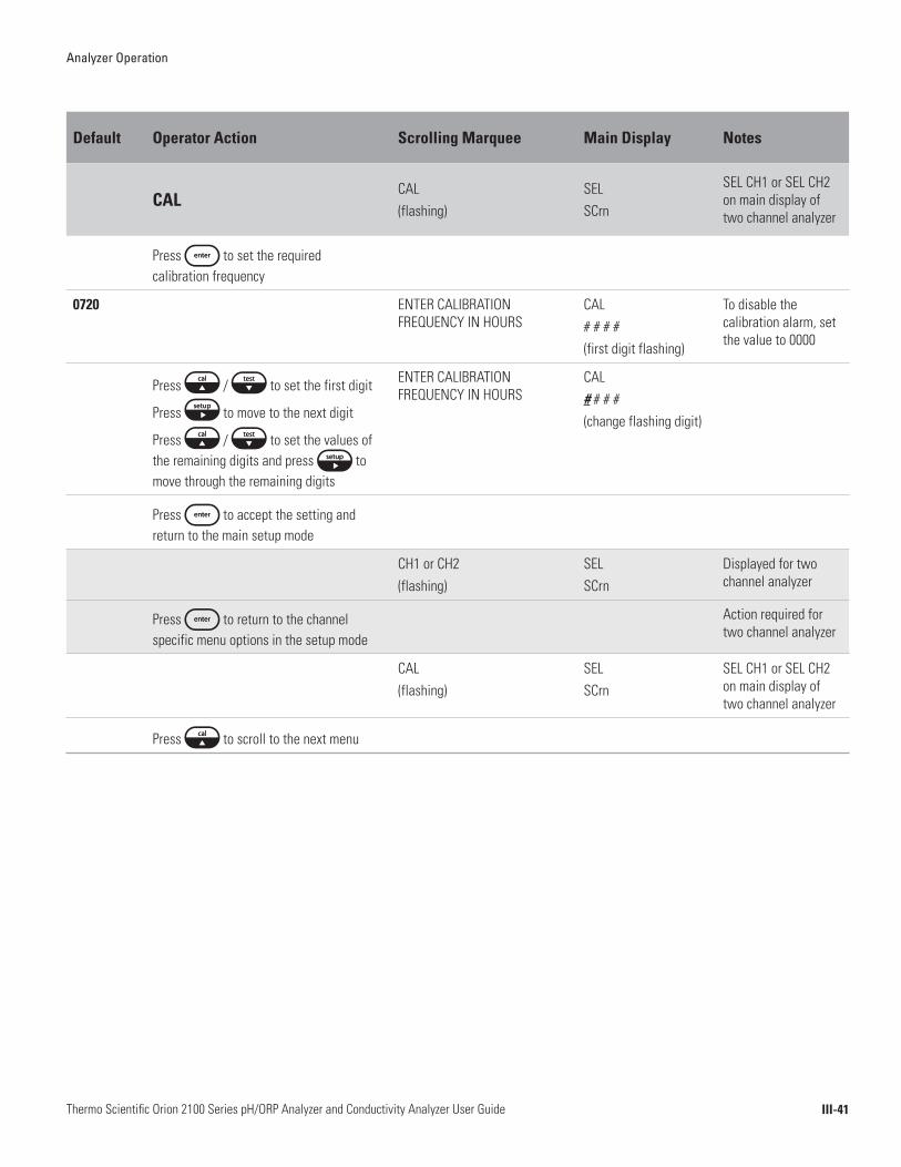
Analyzer Operation
III-41Thermo Scientific Orion 2100 Series pH/ORP Analyzer and Conductivity Analyzer User Guide
Default Operator Action Scrolling Marquee Main Display Notes
CALCAL(flashing)
SELSCrn
SEL CH1 or SEL CH2 on main display of two channel analyzer
Press to set the required calibration frequency
0720 ENTER CALIBRATION FREQUENCY IN HOURS
CAL# # # #(first digit flashing)
To disable the calibration alarm, set the value to 0000
Press / to set the first digit
Press to move to the next digit
Press / to set the values of the remaining digits and press to move through the remaining digits
ENTER CALIBRATION FREQUENCY IN HOURS
CAL# # # #(change flashing digit)
Press to accept the setting and return to the main setup mode
CH1 or CH2(flashing)
SELSCrn
Displayed for two channel analyzer
Press to return to the channel specific menu options in the setup mode
Action required for two channel analyzer
CAL(flashing)
SELSCrn
SEL CH1 or SEL CH2 on main display of two channel analyzer
Press to scroll to the next menu
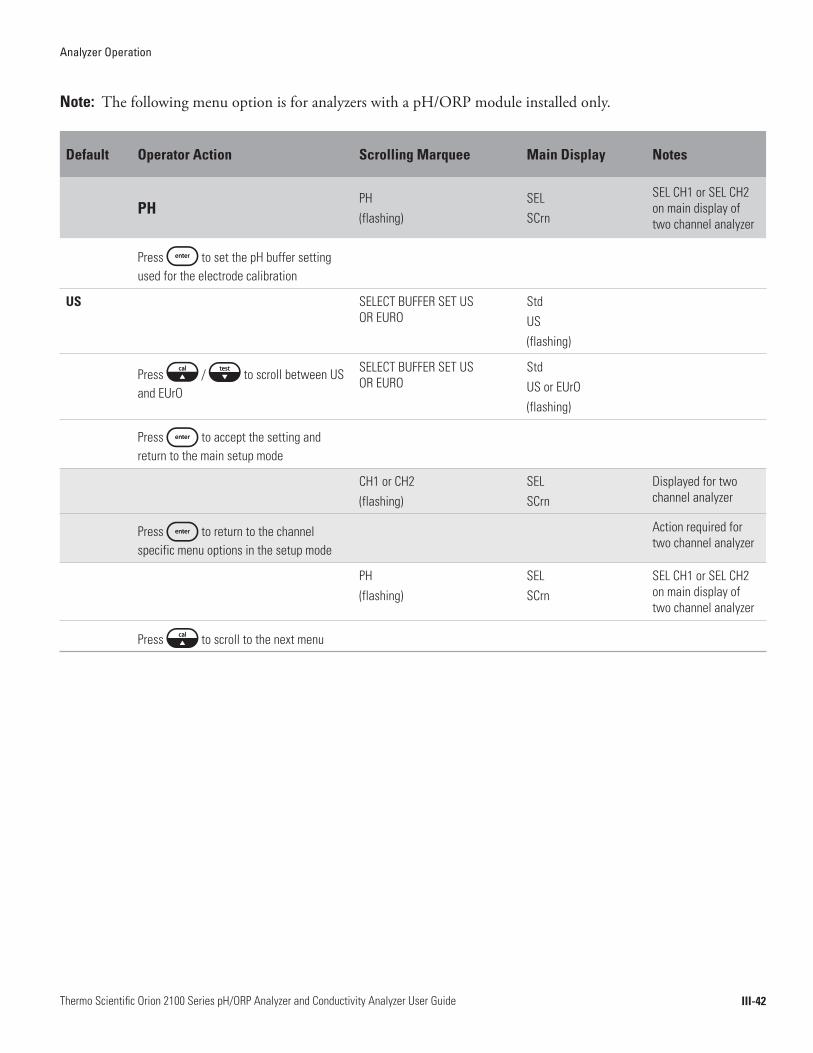
Analyzer Operation
III-42Thermo Scientific Orion 2100 Series pH/ORP Analyzer and Conductivity Analyzer User Guide
Note: The following menu option is for analyzers with a pH/ORP module installed only.
Default Operator Action Scrolling Marquee Main Display Notes
PH PH (flashing)
SELSCrn
SEL CH1 or SEL CH2 on main display of two channel analyzer
Press to set the pH buffer setting used for the electrode calibration
US SELECT BUFFER SET US OR EURO
StdUS(flashing)
Press / to scroll between US and EUrO
SELECT BUFFER SET US OR EURO
StdUS or EUrO(flashing)
Press to accept the setting and return to the main setup mode
CH1 or CH2(flashing)
SELSCrn
Displayed for two channel analyzer
Press to return to the channel specific menu options in the setup mode
Action required for two channel analyzer
PH(flashing)
SELSCrn
SEL CH1 or SEL CH2 on main display of two channel analyzer
Press to scroll to the next menu

Analyzer Operation
III-43Thermo Scientific Orion 2100 Series pH/ORP Analyzer and Conductivity Analyzer User Guide
Note: The following menu option is for analyzers with a conductivity board installed only.
Default Operator Action Scrolling Marquee Main Display Notes
COND COND (flashing)
SELSCrn
SEL CH1 or SEL CH2 on main display of two channel analyzer
Press to set the conductivity cell constant setting used for the calibration
0.100 SET NOMINAL CELL CONSTANT FOR AUTO-STANDARD RECOGNITION
CELL# . # # # (first digit flashing)
Press to move the decimal point
Press / to set the first digit
Press to move to the next digit
Press / to set the values of the remaining digits and press to move through the remaining digits
SET NOMINAL CELL CONSTANT FOR AUTO-STANDARD RECOGNITION
CELL# . # # # (change flashing digit)
Press to accept the setting and return to the main setup mode
CH1 or CH2(flashing)
SELSCrn
Displayed for two channel analyzer
Press to return to the channel specific menu options in the setup mode
Action required for two channel analyzer
COND(flashing)
SELSCrn
SEL CH1 or SEL CH2 on main display of two channel analyzer
Press to scroll to the next menu

IV-1Thermo Scientific Orion 2100 Series pH/ORP Analyzer and Conductivity Analyzer User Guide
Chapter IV Calibration
The Thermo Scientific Orion 2100 series pH/ORP and conductivity analyzers provide simple and fast calibration cycles that quickly have your system back online with security and confidence.
Prior to performing a calibration, refer to Chapter III, Use of the Setup Mode for instructions on how to properly configure the analyzer.
Maximum system accuracy is ensured by performing a fast and easy calibration in the expected sample pH range. Select one pH buffer that is closest to the expected sample pH or select two or three pH buffers that bracket the expected sample pH. Two or three pH buffers are recommended for the most accurate calibration.
• Prepare the pH electrode according to the instructions in the pH electrode user guide or instruction sheet.
• Always pour fresh pH buffers into clean beakers for calibration. If using more than one buffer, select buffers that are one to four pH units apart.
• The filling solution level inside of the electrode must be at least one inch above the buffer solution level during calibration.
• The buffer solution level must be above the pH electrode reference junction when the electrode is immersed in the buffer.
• Between buffers, rinse the electrode with distilled or de-ionized water and then with the next buffer. To reduce the chance of error due to polarization, avoid rubbing or wiping the electrode bulb. Use a lint-free tissue and gently blot the bulb.
Calibration Overview
pH Calibration Setup
pH Calibration Recommendations

Calibration
IV-2Thermo Scientific Orion 2100 Series pH/ORP Analyzer and Conductivity Analyzer User Guide
A one, two or three point calibration, using fresh pH buffers, should be performed before pH measurements are taken. It is recommended that a two or three point calibration be performed at least once per month to determine the slope of the electrode and to verify that the electrode is working properly. A one point calibration can be performed periodically to correct for electrode drift. Whenever a new electrode is installed, it must be calibrated before it can be used to perform accurate measurements.
For the best calibration results, the buffer conditions should be similar to the sample conditions. It is also recommended that an ATC probe be used during the calibration if an ATC probe is used in the sample and the sample measurements are being temperature compensated.
When performing a pH calibration, the operator must choose to use the automatic buffer recognition feature or perform a manual calibration. When using the automatic buffer recognition feature, the analyzer uses the mV readings of the pH electrode to automatically identify the pH buffer values during the calibration. When performing a manual calibration, the operator must enter the pH buffer values during the calibration.
When using the automatic buffer recognition feature, select the pH buffer set that will be used for the automatic buffer recognition feature in the setup mode (the US buffer set includes pH 1.68, 4.01, 7.00, 10.01 and 12.46 buffers and the EUrO buffer set includes pH 1.68, 4.01, 6.86 and 9.18 buffers).
To use the automatic buffer recognition feature, the mV readings of the pH electrode must be in the ranges listed in the following table.
Buffer mV Range Buffer mV Range
1.68 +285 to +345 9.18 -99 to -159
4.01 +207 to +147 10.01 -207 to -147
6.86 +38 to -22 12.46 -293 to -353
7.00 - 30 to + 30
The calibration parameters must be entered in the setup mode prior to performing a calibration. Refer to Chapter III, Use of the Setup Mode and Chapter IV, pH Calibration Setup.
pH Calibration Procedure
Automatic Buffer Recognition or
Manual Calibration
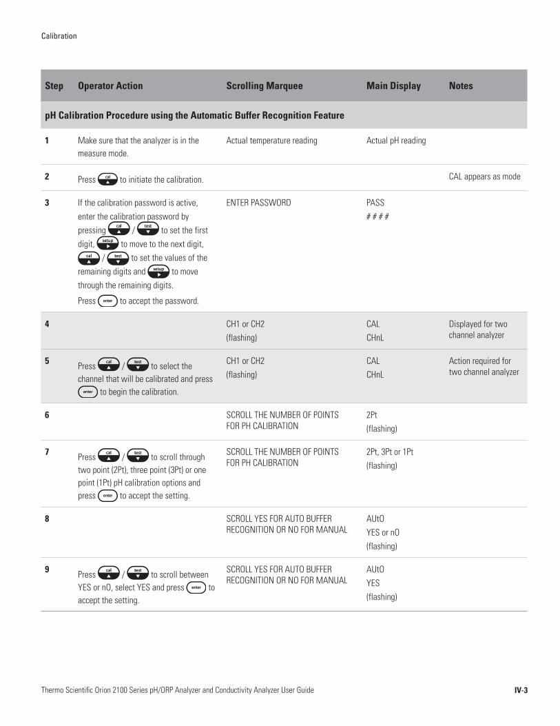
Calibration
IV-3Thermo Scientific Orion 2100 Series pH/ORP Analyzer and Conductivity Analyzer User Guide
Step Operator Action Scrolling Marquee Main Display Notes
pH Calibration Procedure using the Automatic Buffer Recognition Feature
1 Make sure that the analyzer is in the measure mode.
Actual temperature reading Actual pH reading
2 Press to initiate the calibration. CAL appears as mode
3 If the calibration password is active, enter the calibration password by pressing / to set the first digit, to move to the next digit,
/ to set the values of the remaining digits and to move through the remaining digits.
Press to accept the password.
ENTER PASSWORD PASS# # # #
4 CH1 or CH2(flashing)
CALCHnL
Displayed for two channel analyzer
5 Press / to select the channel that will be calibrated and press
to begin the calibration.
CH1 or CH2(flashing)
CALCHnL
Action required for two channel analyzer
6 SCROLL THE NUMBER OF POINTS FOR PH CALIBRATION
2Pt(flashing)
7 Press / to scroll through two point (2Pt), three point (3Pt) or one point (1Pt) pH calibration options and press to accept the setting.
SCROLL THE NUMBER OF POINTS FOR PH CALIBRATION
2Pt, 3Pt or 1Pt(flashing)
8 SCROLL YES FOR AUTO BUFFER RECOGNITION OR NO FOR MANUAL
AUtOYES or nO(flashing)
9 Press / to scroll between YES or nO, select YES and press to accept the setting.
SCROLL YES FOR AUTO BUFFER RECOGNITION OR NO FOR MANUAL
AUtOYES(flashing)
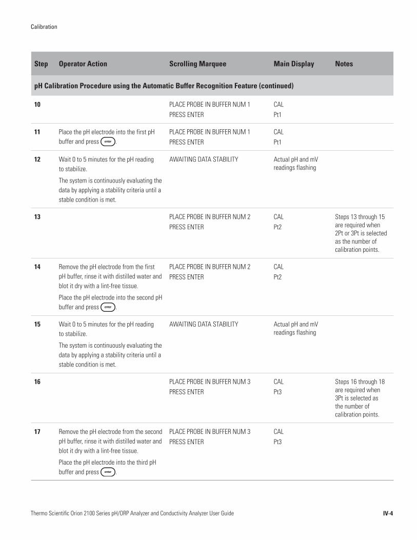
Calibration
IV-4Thermo Scientific Orion 2100 Series pH/ORP Analyzer and Conductivity Analyzer User Guide
Step Operator Action Scrolling Marquee Main Display Notes
pH Calibration Procedure using the Automatic Buffer Recognition Feature (continued)
10 PLACE PROBE IN BUFFER NUM 1 PRESS ENTER
CALPt1
11 Place the pH electrode into the first pH buffer and press .
PLACE PROBE IN BUFFER NUM 1 PRESS ENTER
CALPt1
12 Wait 0 to 5 minutes for the pH reading to stabilize.
The system is continuously evaluating the data by applying a stability criteria until a stable condition is met.
AWAITING DATA STABILITY Actual pH and mV readings flashing
13 PLACE PROBE IN BUFFER NUM 2 PRESS ENTER
CALPt2
Steps 13 through 15 are required when 2Pt or 3Pt is selected as the number of calibration points.
14 Remove the pH electrode from the first pH buffer, rinse it with distilled water and blot it dry with a lint-free tissue.
Place the pH electrode into the second pH buffer and press .
PLACE PROBE IN BUFFER NUM 2 PRESS ENTER
CALPt2
15 Wait 0 to 5 minutes for the pH reading to stabilize.
The system is continuously evaluating the data by applying a stability criteria until a stable condition is met.
AWAITING DATA STABILITY Actual pH and mV readings flashing
16 PLACE PROBE IN BUFFER NUM 3 PRESS ENTER
CALPt3
Steps 16 through 18 are required when 3Pt is selected as the number of calibration points.
17 Remove the pH electrode from the second pH buffer, rinse it with distilled water and blot it dry with a lint-free tissue.
Place the pH electrode into the third pH buffer and press .
PLACE PROBE IN BUFFER NUM 3 PRESS ENTER
CALPt3
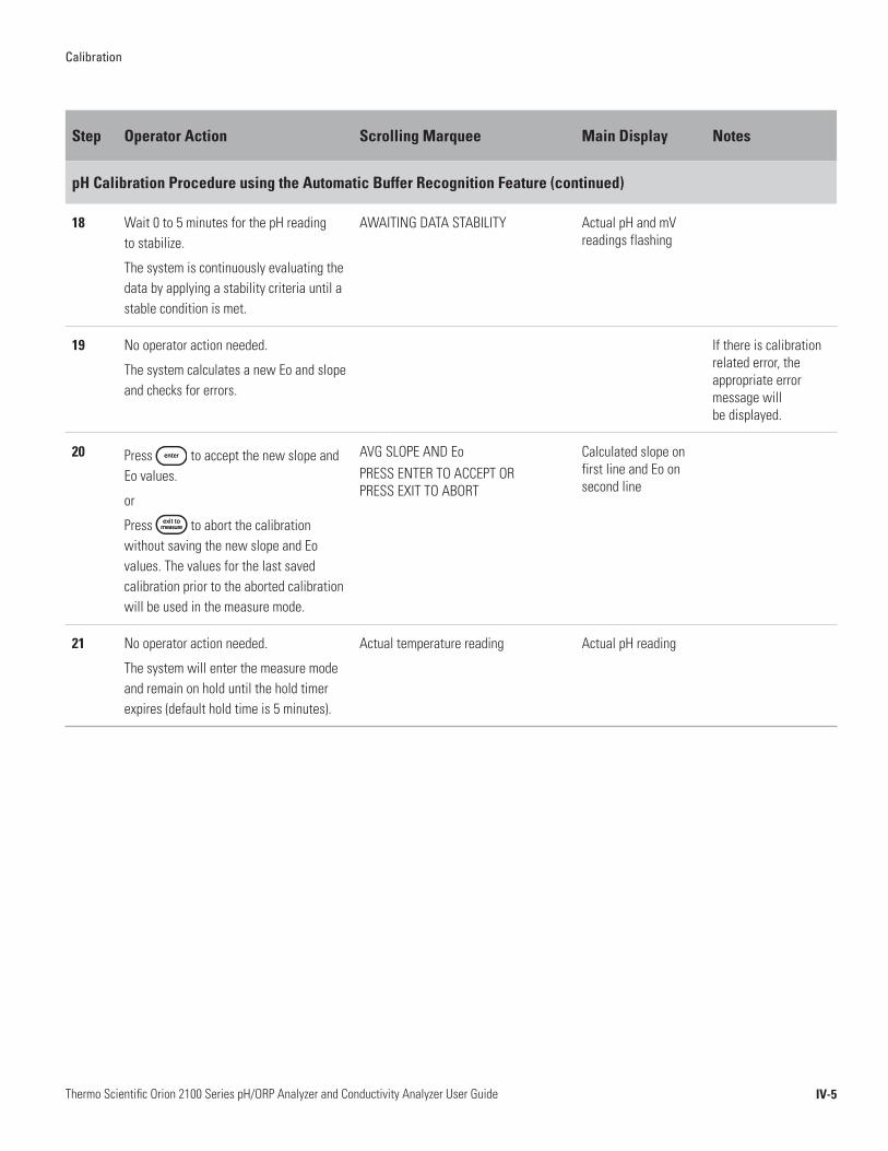
Calibration
IV-5Thermo Scientific Orion 2100 Series pH/ORP Analyzer and Conductivity Analyzer User Guide
Step Operator Action Scrolling Marquee Main Display Notes
pH Calibration Procedure using the Automatic Buffer Recognition Feature (continued)
18 Wait 0 to 5 minutes for the pH reading to stabilize.
The system is continuously evaluating the data by applying a stability criteria until a stable condition is met.
AWAITING DATA STABILITY Actual pH and mV readings flashing
19 No operator action needed.
The system calculates a new Eo and slope and checks for errors.
If there is calibration related error, the appropriate error message will be displayed.
20 Press to accept the new slope and Eo values.
or
Press to abort the calibration without saving the new slope and Eo values. The values for the last saved calibration prior to the aborted calibration will be used in the measure mode.
AVG SLOPE AND EoPRESS ENTER TO ACCEPT OR PRESS EXIT TO ABORT
Calculated slope on first line and Eo on second line
21 No operator action needed.
The system will enter the measure mode and remain on hold until the hold timer expires (default hold time is 5 minutes).
Actual temperature reading Actual pH reading
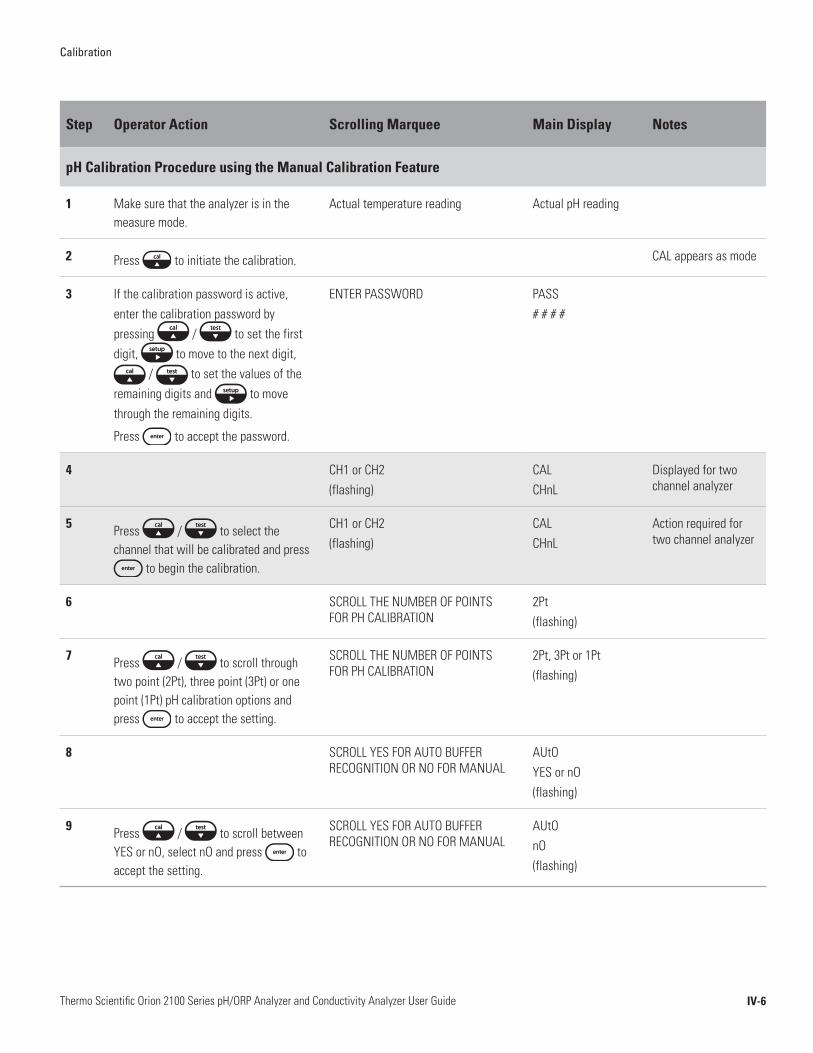
Calibration
IV-6Thermo Scientific Orion 2100 Series pH/ORP Analyzer and Conductivity Analyzer User Guide
Step Operator Action Scrolling Marquee Main Display Notes
pH Calibration Procedure using the Manual Calibration Feature
1 Make sure that the analyzer is in the measure mode.
Actual temperature reading Actual pH reading
2 Press to initiate the calibration. CAL appears as mode
3 If the calibration password is active, enter the calibration password by pressing / to set the first digit, to move to the next digit,
/ to set the values of the remaining digits and to move through the remaining digits.
Press to accept the password.
ENTER PASSWORD PASS# # # #
4 CH1 or CH2(flashing)
CALCHnL
Displayed for two channel analyzer
5 Press / to select the channel that will be calibrated and press
to begin the calibration.
CH1 or CH2(flashing)
CALCHnL
Action required for two channel analyzer
6 SCROLL THE NUMBER OF POINTS FOR PH CALIBRATION
2Pt(flashing)
7 Press / to scroll through two point (2Pt), three point (3Pt) or one point (1Pt) pH calibration options and press to accept the setting.
SCROLL THE NUMBER OF POINTS FOR PH CALIBRATION
2Pt, 3Pt or 1Pt(flashing)
8 SCROLL YES FOR AUTO BUFFER RECOGNITION OR NO FOR MANUAL
AUtOYES or nO(flashing)
9 Press / to scroll between YES or nO, select nO and press to accept the setting.
SCROLL YES FOR AUTO BUFFER RECOGNITION OR NO FOR MANUAL
AUtOnO(flashing)
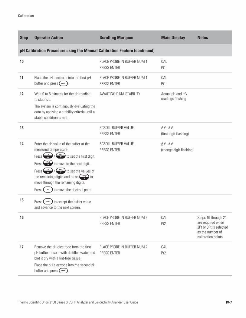
Calibration
IV-7Thermo Scientific Orion 2100 Series pH/ORP Analyzer and Conductivity Analyzer User Guide
Step Operator Action Scrolling Marquee Main Display Notes
pH Calibration Procedure using the Manual Calibration Feature (continued)
10 PLACE PROBE IN BUFFER NUM 1 PRESS ENTER
CALPt1
11 Place the pH electrode into the first pH buffer and press .
PLACE PROBE IN BUFFER NUM 1 PRESS ENTER
CALPt1
12 Wait 0 to 5 minutes for the pH reading to stabilize.
The system is continuously evaluating the data by applying a stability criteria until a stable condition is met.
AWAITING DATA STABILITY Actual pH and mV readings flashing
13 SCROLL BUFFER VALUE PRESS ENTER
# # . # #(first digit flashing)
14 Enter the pH value of the buffer at the measured temperature.
Press / to set the first digit.
Press to move to the next digit.
Press / to set the values of the remaining digits and press to move through the remaining digits.
Press to move the decimal point.
SCROLL BUFFER VALUE PRESS ENTER
# # . # #(change digit flashing)
15 Press to accept the buffer value and advance to the next screen.
16 PLACE PROBE IN BUFFER NUM 2 PRESS ENTER
CALPt2
Steps 16 through 21 are required when 2Pt or 3Pt is selected as the number of calibration points.
17 Remove the pH electrode from the first pH buffer, rinse it with distilled water and blot it dry with a lint-free tissue.
Place the pH electrode into the second pH buffer and press .
PLACE PROBE IN BUFFER NUM 2 PRESS ENTER
CALPt2

Calibration
IV-8Thermo Scientific Orion 2100 Series pH/ORP Analyzer and Conductivity Analyzer User Guide
Step Operator Action Scrolling Marquee Main Display Notes
pH Calibration Procedure using the Manual Calibration Feature (continued)
18 Wait 0 to 5 minutes for the pH reading to stabilize.
The system is continuously evaluating the data by applying a stability criteria until a stable condition is met.
AWAITING DATA STABILITY Actual pH and mV readings flashing
19 SCROLL BUFFER VALUE PRESS ENTER
# # . # #(first digit flashing)
20 Enter the pH value of the buffer at the measured temperature.
Press / to set the first digit.
Press to move to the next digit.
Press / to set the values of the remaining digits and press to move through the remaining digits.
Press to move the decimal point.
SCROLL BUFFER VALUE PRESS ENTER
# # . # #(change digit flashing)
21 Press to accept the buffer value and advance to the next screen.
22 PLACE PROBE IN BUFFER NUM 3 PRESS ENTER
CALPt3
Steps 22 through 27 are required when 3Pt is selected as the number of calibration points.
23 Remove the pH electrode from the second pH buffer, rinse it with distilled water and blot it dry with a lint-free tissue.
Place the pH electrode into the third pH buffer and press .
PLACE PROBE IN BUFFER NUM 3 PRESS ENTER
CALPt3
24 Wait 0 to 5 minutes for the pH reading to stabilize.
The system is continuously evaluating the data by applying a stability criteria until a stable condition is met.
AWAITING DATA STABILITY Actual pH and mV readings flashing
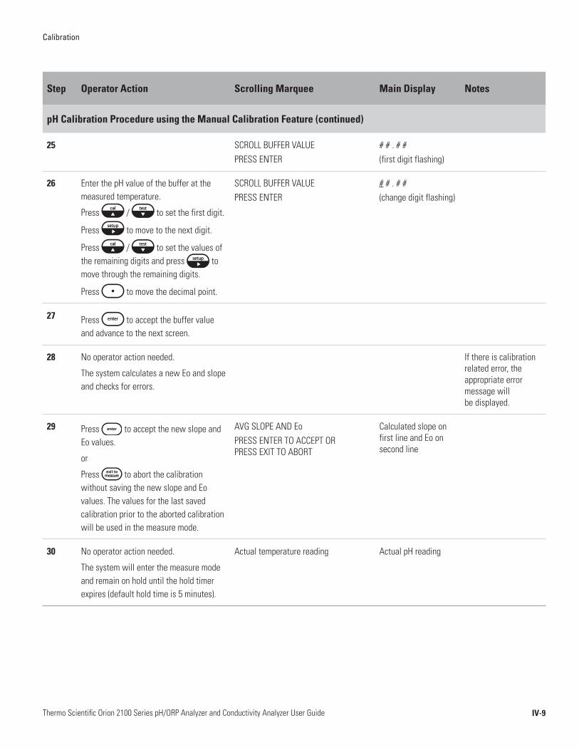
Calibration
IV-9Thermo Scientific Orion 2100 Series pH/ORP Analyzer and Conductivity Analyzer User Guide
Step Operator Action Scrolling Marquee Main Display Notes
pH Calibration Procedure using the Manual Calibration Feature (continued)
25 SCROLL BUFFER VALUE PRESS ENTER
# # . # #(first digit flashing)
26 Enter the pH value of the buffer at the measured temperature.
Press / to set the first digit.
Press to move to the next digit.
Press / to set the values of the remaining digits and press to move through the remaining digits.
Press to move the decimal point.
SCROLL BUFFER VALUE PRESS ENTER
# # . # #(change digit flashing)
27 Press to accept the buffer value and advance to the next screen.
28 No operator action needed.
The system calculates a new Eo and slope and checks for errors.
If there is calibration related error, the appropriate error message will be displayed.
29 Press to accept the new slope and Eo values.
or
Press to abort the calibration without saving the new slope and Eo values. The values for the last saved calibration prior to the aborted calibration will be used in the measure mode.
AVG SLOPE AND EoPRESS ENTER TO ACCEPT OR PRESS EXIT TO ABORT
Calculated slope on first line and Eo on second line
30 No operator action needed.
The system will enter the measure mode and remain on hold until the hold timer expires (default hold time is 5 minutes).
Actual temperature reading Actual pH reading

Calibration
IV-10Thermo Scientific Orion 2100 Series pH/ORP Analyzer and Conductivity Analyzer User Guide
Maximum system accuracy is ensured by performing a fast and easy calibration in the expected sample mV range. ORP readings can be measured using the relative mV value or EH mV value of the sample, depending on the preferred reporting method of the operator. The relative mV value is a calibrated mV measurement that provides standardized mV readings among many ORP electrodes. The EH mV value is a calibrated mV measurement that provides the mV readings corresponding to what would be obtained using a Standard Hydrogen Electrode (SHE), also known as a Normal Hydrogen Electrode (NHE). ORP standard allows operators to calibrate their ORP measurements to the Standard Hydrogen Electrode if they are using a Thermo Scientific Orion ORP electrode and Thermo Scientific Orion ORP standard (Cat. No. 967961 and 967901). The operator must either use an automatic temperature compensation (ATC) probe or set the sample temperature value in the setup mode.
• Prepare the ORP electrode according to the instructions in the ORP electrode user guide or instruction sheet.
• Always pour fresh ORP standard into a clean beaker for calibration.
• The filling solution level inside of the electrode must be at least one inch above the standard solution level during calibration.
• The standard solution level must be above the ORP electrode reference junction when the electrode is immersed in the standard.
• Before calibration, rinse the electrode with distilled or de-ionized water and then with the ORP standard. To reduce the chance of error due to polarization, avoid rubbing or wiping the measuring element. Use a lint-free tissue and gently blot the measuring element.
ORP Calibration Setup
ORP Calibration Recommendations
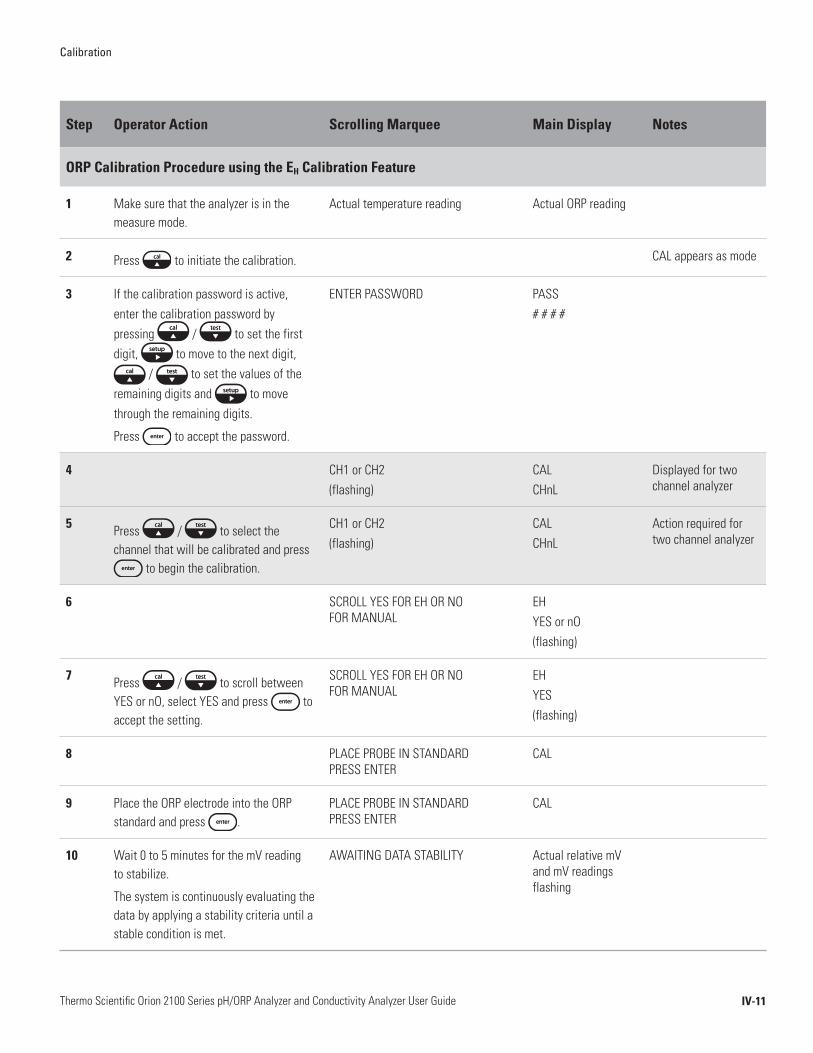
Calibration
IV-11Thermo Scientific Orion 2100 Series pH/ORP Analyzer and Conductivity Analyzer User Guide
Step Operator Action Scrolling Marquee Main Display Notes
ORP Calibration Procedure using the EH Calibration Feature
1 Make sure that the analyzer is in the measure mode.
Actual temperature reading Actual ORP reading
2 Press to initiate the calibration. CAL appears as mode
3 If the calibration password is active, enter the calibration password by pressing / to set the first digit, to move to the next digit,
/ to set the values of the remaining digits and to move through the remaining digits.
Press to accept the password.
ENTER PASSWORD PASS# # # #
4 CH1 or CH2(flashing)
CALCHnL
Displayed for two channel analyzer
5 Press / to select the channel that will be calibrated and press
to begin the calibration.
CH1 or CH2(flashing)
CALCHnL
Action required for two channel analyzer
6 SCROLL YES FOR EH OR NO FOR MANUAL
EHYES or nO(flashing)
7 Press / to scroll between YES or nO, select YES and press to accept the setting.
SCROLL YES FOR EH OR NO FOR MANUAL
EHYES (flashing)
8 PLACE PROBE IN STANDARD PRESS ENTER
CAL
9 Place the ORP electrode into the ORP standard and press .
PLACE PROBE IN STANDARD PRESS ENTER
CAL
10 Wait 0 to 5 minutes for the mV reading to stabilize.
The system is continuously evaluating the data by applying a stability criteria until a stable condition is met.
AWAITING DATA STABILITY Actual relative mV and mV readings flashing

Calibration
IV-12Thermo Scientific Orion 2100 Series pH/ORP Analyzer and Conductivity Analyzer User Guide
Step Operator Action Scrolling Marquee Main Display Notes
ORP Calibration Procedure using the EH Calibration Feature (continued)
11 No operator action needed.
The system calculates a new mV offset and checks for errors.
ORP OFFSET PRESS ENTER TO ACCEPT OR PRESS EXIT TO ABORT
Calculated mV offset on second line
If there is calibration related error, the appropriate error message will be displayed.
12 Press to accept the new mV offset.
or
Press to abort the calibration without saving the new mV offset value. The value for the last saved calibration prior to the aborted calibration will be used in the measure mode.
ORP OFFSET PRESS ENTER TO ACCEPT OR PRESS EXIT TO ABORT
Calculated mV offset on second line
13 No operator action needed.
The system will enter the measure mode and remain on hold until the hold timer expires (default hold time is 5 minutes).
Actual temperature reading Actual ORP reading

Calibration
IV-13Thermo Scientific Orion 2100 Series pH/ORP Analyzer and Conductivity Analyzer User Guide
Step Operator Action Scrolling Marquee Main Display Notes
ORP Calibration Procedure using the Manual Calibration Feature
1 Make sure that the analyzer is in the measure mode.
Actual temperature reading Actual ORP reading
2 Press to initiate the calibration. CAL appears as mode
3 If the calibration password is active, enter the calibration password by pressing / to set the first digit, to move to the next digit,
/ to set the values of the remaining digits and to move through the remaining digits.
Press to accept the password.
ENTER PASSWORD PASS# # # #
4 CH1 or CH2(flashing)
CALCHnL
Displayed for two channel analyzer
5 Press / to select the channel that will be calibrated and press
to begin the calibration.
CH1 or CH2(flashing)
CALCHnL
Action required for two channel analyzer
6 SCROLL YES FOR EH OR NO FOR MANUAL
EHYES or nO(flashing)
7 Press / to scroll between YES or nO, select nO and press to accept the setting.
SCROLL YES FOR EH OR NO FOR MANUAL
EHnO (flashing)
8 PLACE PROBE IN STANDARD PRESS ENTER
CAL
9 Place the ORP electrode into the ORP standard and press .
PLACE PROBE IN STANDARD PRESS ENTER
CAL
10 Wait 0 to 5 minutes for the mV reading to stabilize.
The system is continuously evaluating the data by applying a stability criteria until a stable condition is met.
AWAITING DATA STABILITY Actual relative mV and mV readings flashing
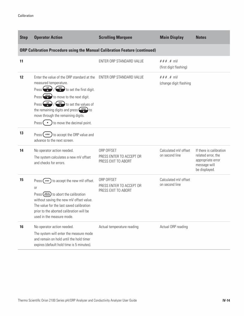
Calibration
IV-14Thermo Scientific Orion 2100 Series pH/ORP Analyzer and Conductivity Analyzer User Guide
Step Operator Action Scrolling Marquee Main Display Notes
ORP Calibration Procedure using the Manual Calibration Feature (continued)
11 ENTER ORP STANDARD VALUE # # # . # mV(first digit flashing)
12 Enter the value of the ORP standard at the measured temperature.
Press / to set the first digit.
Press to move to the next digit.
Press / to set the values of the remaining digits and press to move through the remaining digits.
Press to move the decimal point.
ENTER ORP STANDARD VALUE # # # . # mV(change digit flashing
13 Press to accept the ORP value and advance to the next screen.
14 No operator action needed.
The system calculates a new mV offset and checks for errors.
ORP OFFSET PRESS ENTER TO ACCEPT OR PRESS EXIT TO ABORT
Calculated mV offset on second line
If there is calibration related error, the appropriate error message will be displayed.
15 Press to accept the new mV offset.
or
Press to abort the calibration without saving the new mV offset value. The value for the last saved calibration prior to the aborted calibration will be used in the measure mode.
ORP OFFSET PRESS ENTER TO ACCEPT OR PRESS EXIT TO ABORT
Calculated mV offset on second line
16 No operator action needed.
The system will enter the measure mode and remain on hold until the hold timer expires (default hold time is 5 minutes).
Actual temperature reading Actual ORP reading

Calibration
IV-15Thermo Scientific Orion 2100 Series pH/ORP Analyzer and Conductivity Analyzer User Guide
Maximum system accuracy is ensured by performing a fast and easy calibration in the expected sample conductivity range. Select one conductivity standard that is closest to the expected sample conductivity or select two or three conductivity standards that bracket the expected sample conductivity.
An automatic calibration is performed by entering the nominal cell constant in the setup mode prior to calibration, immersing the conductivity probe in a conductivity standard and initiating the calibration. When the reading stabilizes, the analyzer displays the calibration standard value at 25 °C. Once the calibration is accepted, the analyzer calculates and displays the actual cell constant. The analyzer is capable of automatically recognizing 100 μS/cm, 1413 μS/cm and 12.9 mS/cm conductivity standards when the nominal cell constant of the conductivity probe is entered in the setup mode. For the analyzer to recognize the conductivity standard, enter the nominal cell constant of the conductivity probe that is attached to the analyzer (usually 0.1 cm-1 , 0.475 cm-1 or 1.0 cm-1).
A direct calibration is performed by immersing the conductivity probe in a calibration standard and then entering the conductivity standard value at the measured temperature so the correct cell constant value is displayed. A direct calibration requires a chart of the calibration standard values at different temperatures or the calibration can be performed with the calibration standard at 25 °C.
A manual calibration is performed by immersing the conductivity probe in a calibration standard and then entering the cell constant value so the correct conductivity standard value at the measured temperature is displayed. A manual calibration requires a chart of the calibration standard values at different temperatures or the calibration can be performed with the calibration standard at 25 °C.
• Prepare the conductivity probe according to the instructions in the conductivity probe user guide or instruction sheet.
• Always pour fresh conductivity standards into clean beakers for calibration. If using more than one conductivity standard, select conductivity standards that bracket the expected sample conductivity.
• The conductivity probe must be placed in the conductivity standard so the measuring electrodes and temperature sensor are fully immersed in the conductivity standard.
• Between conductivity standards, rinse the probe with distilled or de-ionized water and then with the next conductivity standard. To reduce the chance of error due to polarization, avoid rubbing or wiping the measuring electrodes. Use a lint-free tissue and gently blot the probe.
Conductivity Calibration Setup
Conductivity Calibration Recommendations
Automatic Calibration, Direct Calibration or
Manual Calibration

Calibration
IV-16Thermo Scientific Orion 2100 Series pH/ORP Analyzer and Conductivity Analyzer User Guide
Step Operator Action Scrolling Marquee Main Display Notes
Conductivity Calibration Procedure using the Automatic Calibration Feature
1 Make sure that the analyzer is in the measure mode.
Actual temperature reading Actual conductivity reading
2 Press to initiate the calibration. CAL appears as mode
3 If the calibration password is active, enter the calibration password by pressing / to set the first digit, to move to the next digit,
/ to set the values of the remaining digits and to move through the remaining digits.
Press to accept the password.
ENTER PASSWORD PASS# # # #
4 CH1 or CH2(flashing)
CALCHnL
Displayed for two channel analyzer
5 Press / to select the channel that will be calibrated and press
to begin the calibration.
CH1 or CH2(flashing)
CALCHnL
Action required for two channel analyzer
6 SELECT ENTERING CELL CONSTANT OR USING STANDARDS
Stnd or CELL(flashing)
7 Press / to scroll between Stnd or CELL, select Stnd and press to accept the setting.
SELECT ENTERING CELL CONSTANT OR USING STANDARDS
Stnd(flashing)
8 SCROLL THE NUMBER OF POINTS FOR CONDUCTIVITY CALIBRATION
2Pt, 3Pt or 1Pt(flashing)
9 Press / to scroll through two point (2Pt), three point (3Pt) or one point (1Pt) conductivity calibration options and press to accept the setting.
SCROLL THE NUMBER OF POINTS FOR CONDUCTIVITY CALIBRATION
2Pt, 3Pt or 1Pt(flashing)
10 SCROLL YES FOR AUTO STANDARD RECOGNITION OR NO FOR MANUAL
AUtOYES or nO(flashing)

Calibration
IV-17Thermo Scientific Orion 2100 Series pH/ORP Analyzer and Conductivity Analyzer User Guide
Step Operator Action Scrolling Marquee Main Display Notes
Conductivity Calibration Procedure using the Automatic Calibration Feature (continued)
11 Press / to scroll between YES or nO, select YES and press to accept the setting.
SCROLL YES FOR AUTO STANDARD RECOGNITION OR NO FOR MANUAL
AUtOYES(flashing)
12 PLACE PROBE IN STANDARD NUM 1 PRESS ENTER
CALPt1
13 Place the conductivity probe into the first standard and press .
PLACE PROBE IN STANDARD NUM 1 PRESS ENTER
CALPt1
14 Wait 0 to 5 minutes for the conductivity reading to stabilize.
The system is continuously evaluating the data by applying a stability criteria until a stable condition is met.
AWAITING DATA STABILITY Actual conductivity reading flashing
15 PLACE PROBE IN STANDARD NUM 2 PRESS ENTER
CALPt2
Steps 15 through 17 are required when 2Pt or 3Pt is selected as the number of calibration points.
16 Remove the conductivity probe from the first standard, rinse it with distilled water and blot it dry with a lint-free tissue.
Place the conductivity probe into the second standard and press .
PLACE PROBE IN STANDARD NUM 2 PRESS ENTER
CALPt2
17 Wait 0 to 5 minutes for the conductivity reading to stabilize.
The system is continuously evaluating the data by applying a stability criteria until a stable condition is met.
AWAITING DATA STABILITY Actual conductivity reading flashing
18 PLACE PROBE IN STANDARD NUM 3 PRESS ENTER
CALPt3
Steps 18 through 20 are required when 3Pt is selected as the number of calibration points.

Calibration
IV-18Thermo Scientific Orion 2100 Series pH/ORP Analyzer and Conductivity Analyzer User Guide
Step Operator Action Scrolling Marquee Main Display Notes
Conductivity Calibration Procedure using the Automatic Calibration Feature (continued)
19 Remove the conductivity probe from the second standard, rinse it with distilled water and blot it dry with a lint-free tissue.
Place the conductivity probe into the third standard and press .
PLACE PROBE IN STANDARD NUM 3 PRESS ENTER
CALPt3
20 Wait 0 to 5 minutes for the conductivity reading to stabilize.
The system is continuously evaluating the data by applying a stability criteria until a stable condition is met.
AWAITING DATA STABILITY Actual conductivity reading flashing
21 No operator action needed.
The system calculates a new cell constant and checks for errors.
If there is calibration related error, the appropriate error message will be displayed.
22 Press to accept the new cell constant value.
or
Press to abort the calibration without saving the new slope and Eo values. The values for the last saved calibration prior to the aborted calibration will be used in the measure mode.
AVG CELL CONSTANTPRESS ENTER TO ACCEPT OR PRESS EXIT TO ABORT
Calculated cell constant on second line
23 No operator action needed.
The system will enter the measure mode and remain on hold until the hold timer expires (default hold time is 5 minutes).
Actual temperature reading Actual conductivity reading
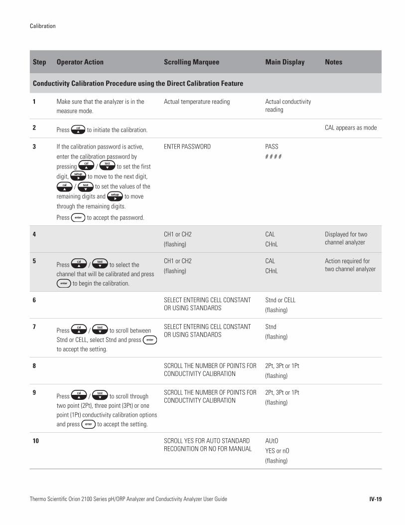
Calibration
IV-19Thermo Scientific Orion 2100 Series pH/ORP Analyzer and Conductivity Analyzer User Guide
Step Operator Action Scrolling Marquee Main Display Notes
Conductivity Calibration Procedure using the Direct Calibration Feature
1 Make sure that the analyzer is in the measure mode.
Actual temperature reading Actual conductivity reading
2 Press to initiate the calibration. CAL appears as mode
3 If the calibration password is active, enter the calibration password by pressing / to set the first digit, to move to the next digit,
/ to set the values of the remaining digits and to move through the remaining digits.
Press to accept the password.
ENTER PASSWORD PASS# # # #
4 CH1 or CH2(flashing)
CALCHnL
Displayed for two channel analyzer
5 Press / to select the channel that will be calibrated and press
to begin the calibration.
CH1 or CH2(flashing)
CALCHnL
Action required for two channel analyzer
6 SELECT ENTERING CELL CONSTANT OR USING STANDARDS
Stnd or CELL(flashing)
7 Press / to scroll between Stnd or CELL, select Stnd and press to accept the setting.
SELECT ENTERING CELL CONSTANT OR USING STANDARDS
Stnd(flashing)
8 SCROLL THE NUMBER OF POINTS FOR CONDUCTIVITY CALIBRATION
2Pt, 3Pt or 1Pt(flashing)
9 Press / to scroll through two point (2Pt), three point (3Pt) or one point (1Pt) conductivity calibration options and press to accept the setting.
SCROLL THE NUMBER OF POINTS FOR CONDUCTIVITY CALIBRATION
2Pt, 3Pt or 1Pt(flashing)
10 SCROLL YES FOR AUTO STANDARD RECOGNITION OR NO FOR MANUAL
AUtOYES or nO(flashing)
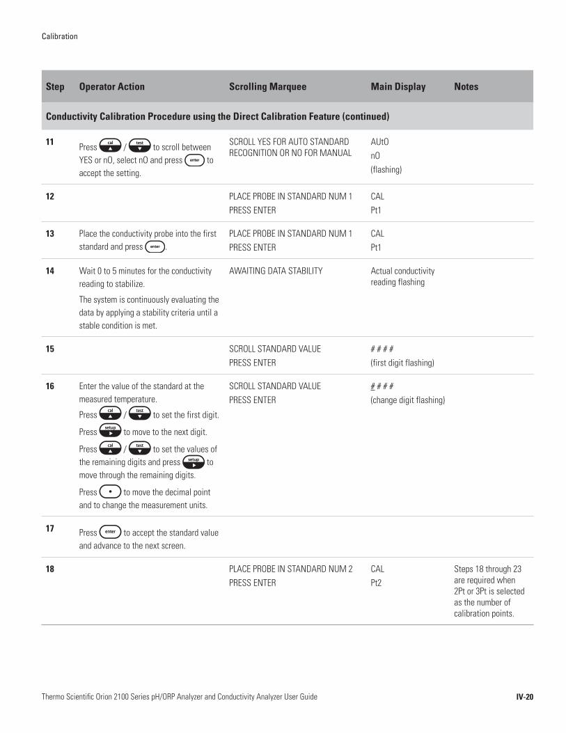
Calibration
IV-20Thermo Scientific Orion 2100 Series pH/ORP Analyzer and Conductivity Analyzer User Guide
Step Operator Action Scrolling Marquee Main Display Notes
Conductivity Calibration Procedure using the Direct Calibration Feature (continued)
11 Press / to scroll between YES or nO, select nO and press to accept the setting.
SCROLL YES FOR AUTO STANDARD RECOGNITION OR NO FOR MANUAL
AUtOnO(flashing)
12 PLACE PROBE IN STANDARD NUM 1 PRESS ENTER
CALPt1
13 Place the conductivity probe into the first standard and press .
PLACE PROBE IN STANDARD NUM 1 PRESS ENTER
CALPt1
14 Wait 0 to 5 minutes for the conductivity reading to stabilize.
The system is continuously evaluating the data by applying a stability criteria until a stable condition is met.
AWAITING DATA STABILITY Actual conductivity reading flashing
15 SCROLL STANDARD VALUE PRESS ENTER
# # # #(first digit flashing)
16 Enter the value of the standard at the measured temperature.
Press / to set the first digit.
Press to move to the next digit.
Press / to set the values of the remaining digits and press to move through the remaining digits.
Press to move the decimal point and to change the measurement units.
SCROLL STANDARD VALUE PRESS ENTER
# # # #(change digit flashing)
17 Press to accept the standard value and advance to the next screen.
18 PLACE PROBE IN STANDARD NUM 2 PRESS ENTER
CALPt2
Steps 18 through 23 are required when 2Pt or 3Pt is selected as the number of calibration points.

Calibration
IV-21Thermo Scientific Orion 2100 Series pH/ORP Analyzer and Conductivity Analyzer User Guide
Step Operator Action Scrolling Marquee Main Display Notes
Conductivity Calibration Procedure using the Direct Calibration Feature (continued)
19 Remove the conductivity probe from the first standard, rinse it with distilled water and blot it dry with a lint-free tissue.
Place the conductivity probe into the second standard and press .
PLACE PROBE IN STANDARD NUM 2 PRESS ENTER
CALPt2
20 Wait 0 to 5 minutes for the conductivity reading to stabilize.
The system is continuously evaluating the data by applying a stability criteria until a stable condition is met.
AWAITING DATA STABILITY Actual conductivity reading flashing
21 SCROLL STANDARD VALUE PRESS ENTER
# # # #(first digit flashing)
22 Enter the value of the standard at the measured temperature.
Press / to set the first digit.
Press to move to the next digit.
Press / to set the values of the remaining digits and press to move through the remaining digits.
Press to move the decimal point and to change the measurement units.
SCROLL STANDARD VALUE PRESS ENTER
# # # #(change digit flashing)
23 Press to accept the standard value and advance to the next screen.
24 PLACE PROBE IN STANDARD NUM 3 PRESS ENTER
CALPt3
Steps 24 through 29 are required when 3Pt is selected as the number of calibration points.
25 Remove the conductivity probe from the second standard, rinse it with distilled water and blot it dry with a lint-free tissue.
Place the conductivity probe into the third standard and press .
PLACE PROBE IN STANDARD NUM 3 PRESS ENTER
CALPt3
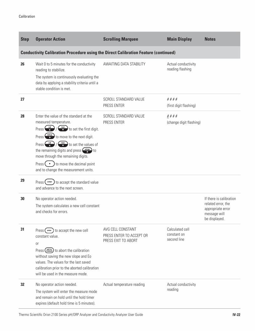
Calibration
IV-22Thermo Scientific Orion 2100 Series pH/ORP Analyzer and Conductivity Analyzer User Guide
Step Operator Action Scrolling Marquee Main Display Notes
Conductivity Calibration Procedure using the Direct Calibration Feature (continued)
26 Wait 0 to 5 minutes for the conductivity reading to stabilize.
The system is continuously evaluating the data by applying a stability criteria until a stable condition is met.
AWAITING DATA STABILITY Actual conductivity reading flashing
27 SCROLL STANDARD VALUE PRESS ENTER
# # # #(first digit flashing)
28 Enter the value of the standard at the measured temperature.
Press / to set the first digit.
Press to move to the next digit.
Press / to set the values of the remaining digits and press to move through the remaining digits.
Press to move the decimal point and to change the measurement units.
SCROLL STANDARD VALUE PRESS ENTER
# # # #(change digit flashing)
29 Press to accept the standard value and advance to the next screen.
30 No operator action needed.
The system calculates a new cell constant and checks for errors.
If there is calibration related error, the appropriate error message will be displayed.
31 Press to accept the new cell constant value.
or
Press to abort the calibration without saving the new slope and Eo values. The values for the last saved calibration prior to the aborted calibration will be used in the measure mode.
AVG CELL CONSTANTPRESS ENTER TO ACCEPT OR PRESS EXIT TO ABORT
Calculated cell constant on second line
32 No operator action needed.
The system will enter the measure mode and remain on hold until the hold timer expires (default hold time is 5 minutes).
Actual temperature reading Actual conductivity reading

Calibration
IV-23Thermo Scientific Orion 2100 Series pH/ORP Analyzer and Conductivity Analyzer User Guide
Step Operator Action Scrolling Marquee Main Display Notes
Conductivity Calibration Procedure using the Manual Calibration Feature
1 Make sure that the analyzer is in the measure mode.
Actual temperature reading Actual conductivity reading
2 Press to initiate the calibration. CAL appears as mode
3 If the calibration password is active, enter the calibration password by pressing / to set the first digit, to move to the next digit,
/ to set the values of the remaining digits and to move through the remaining digits.
Press to accept the password.
ENTER PASSWORD PASS# # # #
4 CH1 or CH2(flashing)
CALCHnL
Displayed for two channel analyzer
5 Press / to select the channel that will be calibrated and press
to begin the calibration.
CH1 or CH2(flashing)
CALCHnL
Action required for two channel analyzer
6 SELECT ENTERING CELL CONSTANT OR USING STANDARDS
Stnd or CELL(flashing)
7 Press / to scroll between Stnd or CELL, select CELL and press to accept the setting.
SELECT ENTERING CELL CONSTANT OR USING STANDARDS
CELL(flashing)
8 SCROLL THE CELL CONSTANT # # # ## # # #(first digit flashing)
9 Place the conductivity probe into the calibration standard.
SCROLL THE CELL CONSTANT # # # ## # # #(first digit flashing)

Calibration
IV-24Thermo Scientific Orion 2100 Series pH/ORP Analyzer and Conductivity Analyzer User Guide
Step Operator Action Scrolling Marquee Main Display Notes
Conductivity Calibration Procedure using the Manual Calibration Feature (continued)
10 Enter the value of the cell constant so the displayed conductivity value matches the conductivity value of the standard at the measured temperature.
Press / to set the first digit.
Press to move to the next digit.
Press / to set the values of the remaining digits and press to move through the remaining digits.
Press to move the decimal point.
SCROLL THE CELL CONSTANT # # # ## # # #(change digit flashing)
The displayed conductivity value is on the first line and the cell constant value is on the second line.
11 Press to accept the standard value and advance to the next screen.
12 Press to accept the new cell constant value.
ACCEPT THE FINAL VALUE Entered cell constant on second line
13 No operator action needed.
The system will enter the measure mode and remain on hold until the hold timer expires (default hold time is 5 minutes).
Actual temperature reading Actual conductivity reading
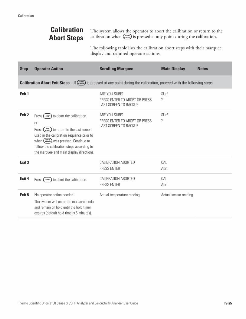
Calibration
IV-25Thermo Scientific Orion 2100 Series pH/ORP Analyzer and Conductivity Analyzer User Guide
The system allows the operator to abort the calibration or return to the calibration when is pressed at any point during the calibration.
The following table lists the calibration abort steps with their marquee display and required operator actions.
Step Operator Action Scrolling Marquee Main Display Notes
Calibration Abort Exit Steps – If is pressed at any point during the calibration, proceed with the following steps
Exit 1 ARE YOU SURE? PRESS ENTER TO ABORT OR PRESS LAST SCREEN TO BACKUP
SUrE?
Exit 2 Press to abort the calibration.
or
Press to return to the last screen used in the calibration sequence prior to when was pressed. Continue to follow the calibration steps according to the marquee and main display directions.
ARE YOU SURE? PRESS ENTER TO ABORT OR PRESS LAST SCREEN TO BACKUP
SUrE?
Exit 3 CALIBRATION ABORTEDPRESS ENTER
CAL Abrt
Exit 4 Press to abort the calibration. CALIBRATION ABORTEDPRESS ENTER
CAL Abrt
Exit 5 No operator action needed.
The system will enter the measure mode and remain on hold until the hold timer expires (default hold time is 5 minutes).
Actual temperature reading Actual sensor reading
Calibration Abort Steps
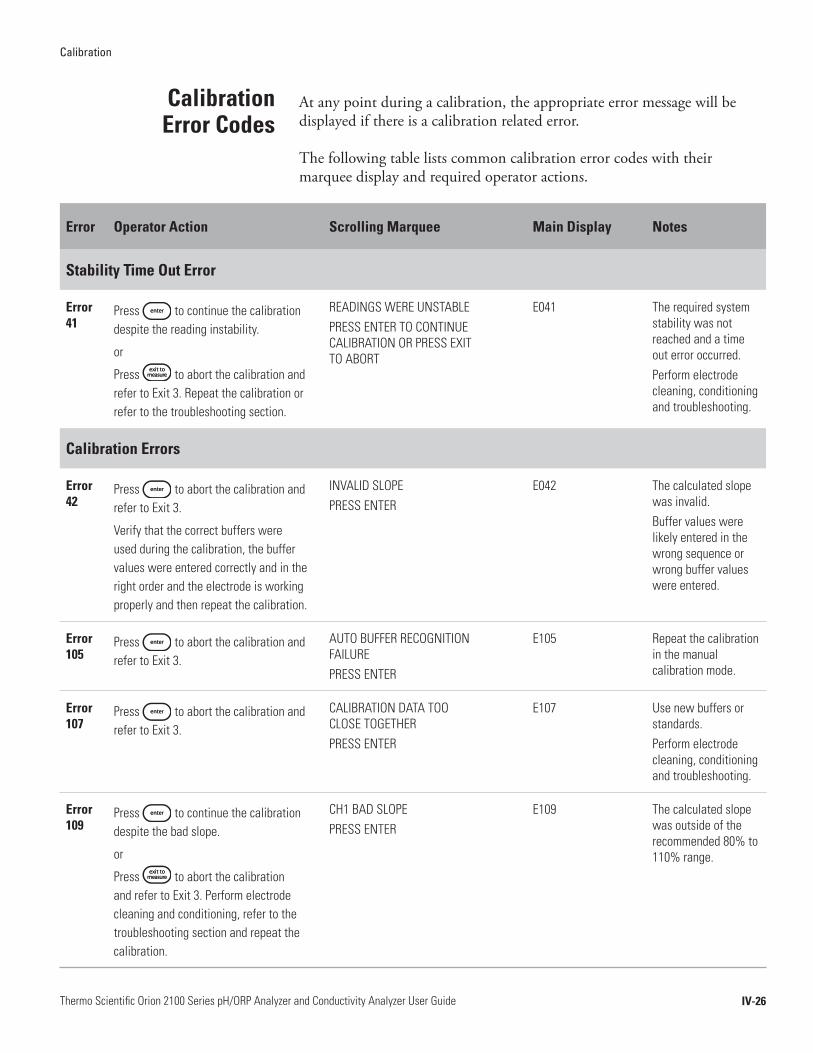
Calibration
IV-26Thermo Scientific Orion 2100 Series pH/ORP Analyzer and Conductivity Analyzer User Guide
At any point during a calibration, the appropriate error message will be displayed if there is a calibration related error.
The following table lists common calibration error codes with their marquee display and required operator actions.
Error Operator Action Scrolling Marquee Main Display Notes
Stability Time Out Error
Error 41
Press to continue the calibration despite the reading instability.
or
Press to abort the calibration and refer to Exit 3. Repeat the calibration or refer to the troubleshooting section.
READINGS WERE UNSTABLEPRESS ENTER TO CONTINUE CALIBRATION OR PRESS EXIT TO ABORT
E041 The required system stability was not reached and a time out error occurred.Perform electrode cleaning, conditioning and troubleshooting.
Calibration Errors
Error 42
Press to abort the calibration and refer to Exit 3.
Verify that the correct buffers were used during the calibration, the buffer values were entered correctly and in the right order and the electrode is working properly and then repeat the calibration.
INVALID SLOPEPRESS ENTER
E042 The calculated slope was invalid. Buffer values were likely entered in the wrong sequence or wrong buffer values were entered.
Error 105
Press to abort the calibration and refer to Exit 3.
AUTO BUFFER RECOGNITION FAILUREPRESS ENTER
E105 Repeat the calibration in the manual calibration mode.
Error 107
Press to abort the calibration and refer to Exit 3.
CALIBRATION DATA TOO CLOSE TOGETHERPRESS ENTER
E107 Use new buffers or standards.Perform electrode cleaning, conditioning and troubleshooting.
Error 109
Press to continue the calibration despite the bad slope.
or
Press to abort the calibration and refer to Exit 3. Perform electrode cleaning and conditioning, refer to the troubleshooting section and repeat the calibration.
CH1 BAD SLOPE PRESS ENTER
E109 The calculated slope was outside of the recommended 80% to 110% range.
Calibration Error Codes

Calibration
IV-27Thermo Scientific Orion 2100 Series pH/ORP Analyzer and Conductivity Analyzer User Guide
Error Operator Action Scrolling Marquee Main Display Notes
Calibration Errors (cont’d)
Error 110
Press to continue the calibration despite the bad slope.
or
Press to abort the calibration and refer to Exit 3. Perform electrode cleaning and conditioning, refer to the troubleshooting section and repeat the calibration.
CH2 BAD SLOPE PRESS ENTER
E110 The calculated slope was outside of the recommended 80% to 110% range.
Error 125
Press to abort the calibration and refer to Exit 3.
Verify that the correct buffers were used during the calibration, the buffer values were entered correctly and in the right order and the electrode is working properly and then repeat the calibration.
CH1 BAD OFFSET PRESS ENTER
E125 Use new buffers or standards.Perform electrode cleaning, conditioning and troubleshooting.
Error 126
Press to abort the calibration and refer to Exit 3.
Verify that the correct buffers were used during the calibration, the buffer values were entered correctly and in the right order and the electrode is working properly and then repeat the calibration.
CH2 BAD OFFSET PRESS ENTER
E126 Use new buffers or standards.Perform electrode cleaning, conditioning and troubleshooting.
V-1Thermo Scientific Orion 2100 Series pH/ORP Analyzer and Conductivity Analyzer User Guide
Chapter V Analyzer Maintenance
The Thermo Scientific Orion 2100 series pH/ORP and conductivity analyzers are designed for simple maintenance. Follow the instructions in this section to ensure proper operation of your analyzer.
To ensure proper maintenance and good analyzer performance, a service logbook should be kept.
• Record the maintenance date and type of service work completed.
• Record the date that solutions are opened and when solutions expire.
• Tag each electrode cable with installation date of the electrode.
1. Check that the sample flow rate is 50 to 100 mL/min.
2. Check that there are no error indications and that the current measurement value is reasonable.
3. Check if the reference fill solution is adequate (if appropriate for the electrodes/probes in use).
4. Wipe the analyzer with a damp cloth to remove dirt and dust particles.
Maintenance Schedule
Weekly Maintenance
Recommendations
Analyzer Maintenance
V-2Thermo Scientific Orion 2100 Series pH/ORP Analyzer and Conductivity Analyzer User Guide
The calibration frequency depends on the operator’s requirements for the most accurate and precise measurements.
• Calibration intervals can be programmed using the setup mode. This will prompt the operator to recalibrate the analyzer after a specific amount of time has passed. Refer to Chapter III, Use of the Setup Mode.
Refer to Chapter II, Installation of a New pH Electrode.
Electrode filling solution is meant to be a several month supply. Therefore, if reservoir is less than one quarter full, replace solution. This should be checked each month to ensure the electrode does not run dry.
1. Prepare the electrode according to the instruction sheet or manual that is packaged with the electrode.
Note: Dispose of all old solutions according to MSDS instructions. Download MSDS files for Thermo Scientific Orion products at www.thermo.com/water.
1. Replace the pH electrode. Refer to Chapter II, Installation of a New pH Electrode for detailed instructions.
2. Replace the sensing electrode (if appropriate for the electrodes/probes in use).
1. Replace the ORP electrode. Refer to Chapter II, Installation of a New ORP Electrode for detailed instructions.
1. Replace the conductivity probe every two years. Refer to Chapter II, Installation of a New Conductivity Probe for detailed instructions.
1. Replace all calibration buffers or standards and all other solutions.
Calibration
Monthly Maintenance
Replacement of Electrode Filling Solution(If Appropriate for the
Electrodes In Use)
Yearly Preventive Maintenance
pH Electrode
ORP Electrode
Conductivity Probe
Calibration Solutions
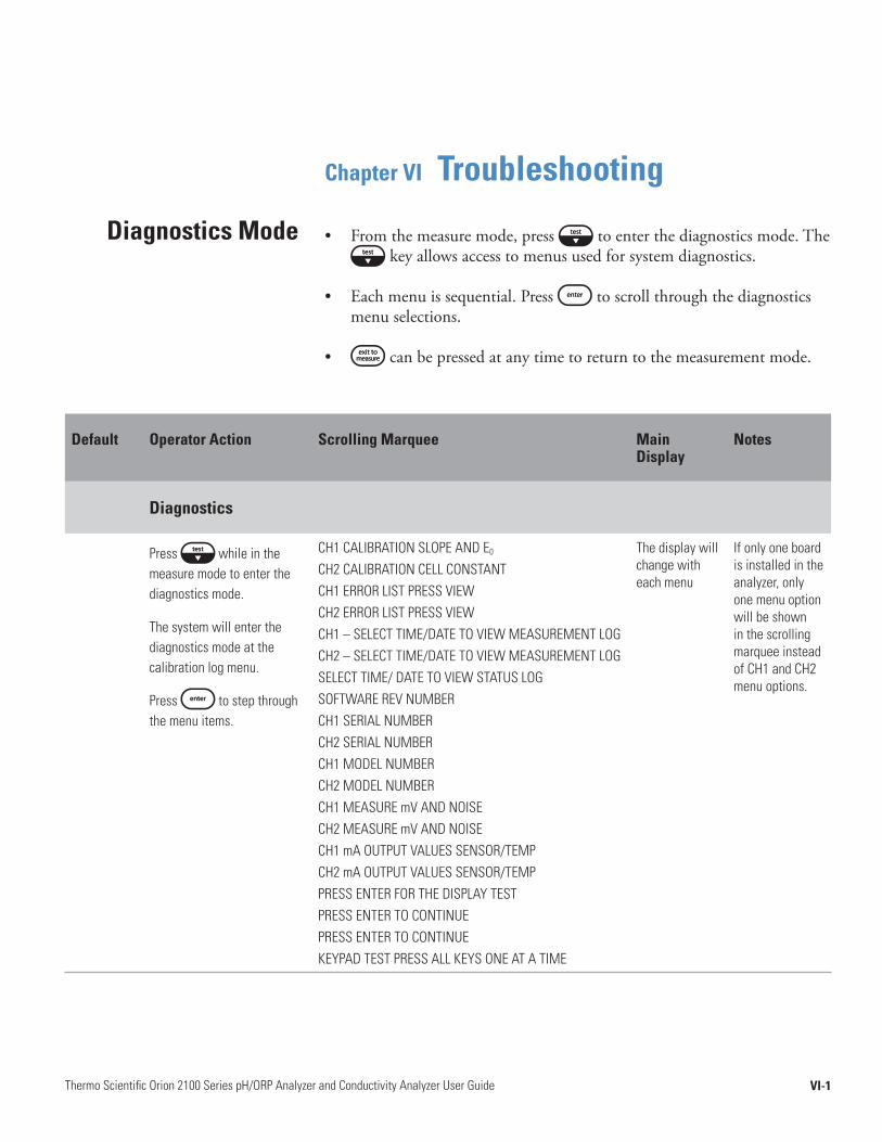
VI-1Thermo Scientific Orion 2100 Series pH/ORP Analyzer and Conductivity Analyzer User Guide
Chapter VI Troubleshooting
• Fromthemeasuremode,press toenterthediagnosticsmode.Thekeyallowsaccesstomenususedforsystemdiagnostics.
• Eachmenuissequential.Press toscrollthroughthediagnosticsmenuselections.
• canbepressedatanytimetoreturntothemeasurementmode.
Diagnostics Mode
Default Operator Action Scrolling Marquee Main Display
Notes
Diagnostics
Press while in the measure mode to enter the diagnostics mode.
The system will enter the diagnostics mode at the calibration log menu.
Press to step through the menu items.
CH1 CALIBRATION SLOPE AND E0
CH2 CALIBRATION CELL CONSTANTCH1 ERROR LIST PRESS VIEWCH2 ERROR LIST PRESS VIEWCH1 – SELECT TIME/DATE TO VIEW MEASUREMENT LOGCH2 – SELECT TIME/DATE TO VIEW MEASUREMENT LOGSELECT TIME/ DATE TO VIEW STATUS LOGSOFTWARE REV NUMBERCH1 SERIAL NUMBERCH2 SERIAL NUMBERCH1 MODEL NUMBERCH2 MODEL NUMBERCH1 MEASURE mV AND NOISECH2 MEASURE mV AND NOISECH1 mA OUTPUT VALUES SENSOR/TEMPCH2 mA OUTPUT VALUES SENSOR/TEMPPRESS ENTER FOR THE DISPLAY TEST PRESS ENTER TO CONTINUEPRESS ENTER TO CONTINUEKEYPAD TEST PRESS ALL KEYS ONE AT A TIME
The display will change with each menu
If only one board is installed in the analyzer, only one menu option will be shown in the scrolling marquee instead of CH1 and CH2 menu options.
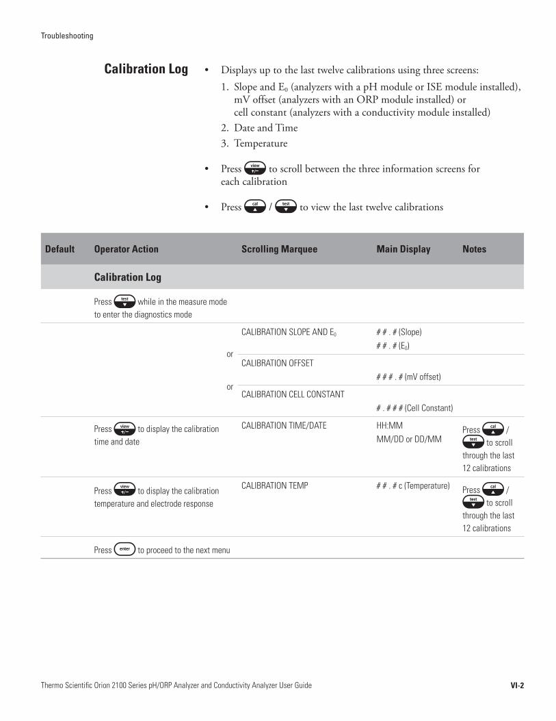
Troubleshooting
VI-2Thermo Scientific Orion 2100 Series pH/ORP Analyzer and Conductivity Analyzer User Guide
• Displaysuptothelasttwelvecalibrationsusingthreescreens:1. SlopeandE0(analyzerswithapHmoduleorISEmoduleinstalled),
mVoffset(analyzerswithanORPmoduleinstalled)orcellconstant(analyzerswithaconductivitymoduleinstalled)
2. DateandTime3. Temperature
• Press toscrollbetweenthethreeinformationscreensforeachcalibration
• Press / toviewthelasttwelvecalibrations
Calibration Log
Default Operator Action Scrolling Marquee Main Display Notes
Calibration Log
Press while in the measure mode to enter the diagnostics mode
or
or
CALIBRATION SLOPE AND E0 # # . # (Slope) # # . # (E0)
CALIBRATION OFFSET# # # . # (mV offset)
CALIBRATION CELL CONSTANT# . # # # (Cell Constant)
Press to display the calibration time and date
CALIBRATION TIME/DATE HH:MMMM/DD or DD/MM
Press / to scroll
through the last 12 calibrations
Press to display the calibration temperature and electrode response
CALIBRATION TEMP # # . # c (Temperature) Press / to scroll
through the last 12 calibrations
Press to proceed to the next menu
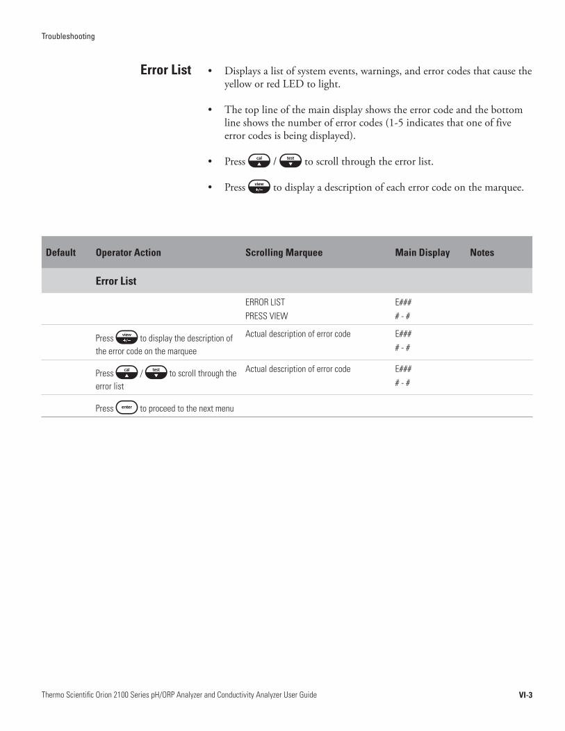
Troubleshooting
VI-3Thermo Scientific Orion 2100 Series pH/ORP Analyzer and Conductivity Analyzer User Guide
• Displaysalistofsystemevents,warnings,anderrorcodesthatcausetheyelloworredLEDtolight.
• Thetoplineofthemaindisplayshowstheerrorcodeandthebottomlineshowsthenumberoferrorcodes(1-5indicatesthatoneoffiveerrorcodesisbeingdisplayed).
• Press / toscrollthroughtheerrorlist.
• Press todisplayadescriptionofeacherrorcodeonthemarquee.
Error List
Default Operator Action Scrolling Marquee Main Display Notes
Error List
ERROR LIST PRESS VIEW
E#### - #
Press to display the description of the error code on the marquee
Actual description of error code E#### - #
Press / to scroll through the error list
Actual description of error code E#### - #
Press to proceed to the next menu
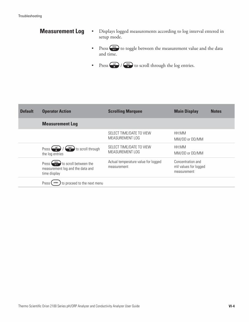
Troubleshooting
VI-4Thermo Scientific Orion 2100 Series pH/ORP Analyzer and Conductivity Analyzer User Guide
• Displaysloggedmeasurementsaccordingtologintervalenteredinsetupmode.
• Press totogglebetweenthemeasurementvalueandthedataandtime.
• Press / toscrollthroughthelogentries.
Measurement Log
Default Operator Action Scrolling Marquee Main Display Notes
Measurement Log
SELECT TIME/DATE TO VIEW MEASUREMENT LOG
HH:MMMM/DD or DD/MM
Press / to scroll through the log entries
SELECT TIME/DATE TO VIEW MEASUREMENT LOG
HH:MM MM/DD or DD/MM
Press to scroll between the measurement log and the data and time display
Actual temperature value for logged measurement
Concentration and mV values for logged measurement
Press to proceed to the next menu
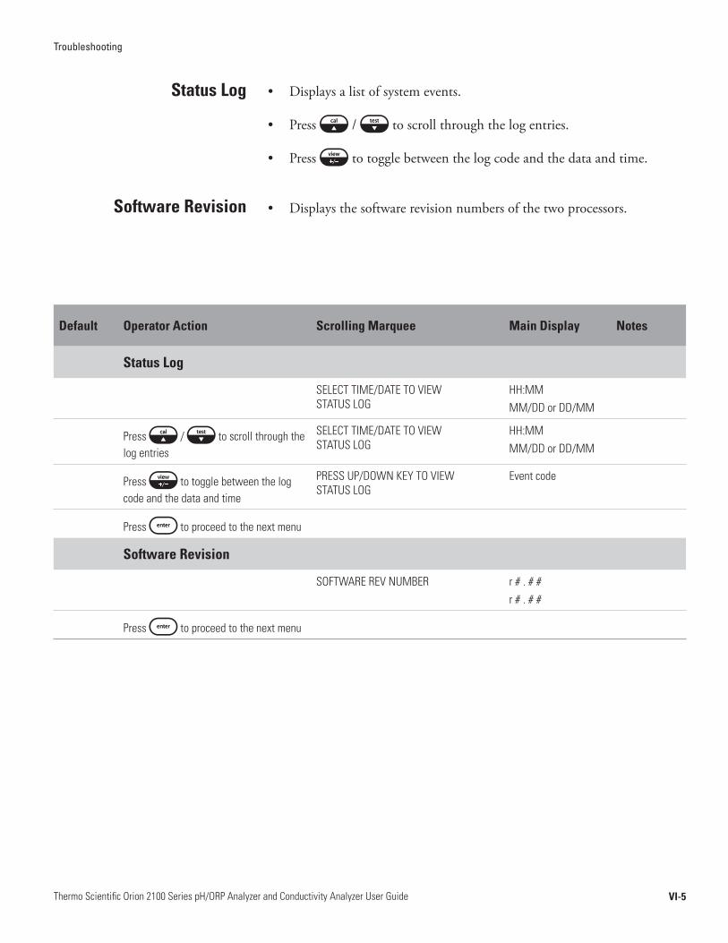
Troubleshooting
VI-5Thermo Scientific Orion 2100 Series pH/ORP Analyzer and Conductivity Analyzer User Guide
• Displaysalistofsystemevents.
• Press / toscrollthroughthelogentries.
• Press totogglebetweenthelogcodeandthedataandtime.
• Displaysthesoftwarerevisionnumbersofthetwoprocessors.
Status Log
Software Revision
Default Operator Action Scrolling Marquee Main Display Notes
Status Log
SELECT TIME/DATE TO VIEW STATUS LOG
HH:MM MM/DD or DD/MM
Press / to scroll through the log entries
SELECT TIME/DATE TO VIEW STATUS LOG
HH:MM MM/DD or DD/MM
Press to toggle between the log code and the data and time
PRESS UP/DOWN KEY TO VIEW STATUS LOG
Event code
Press to proceed to the next menu
Software Revision
SOFTWARE REV NUMBER r # . # #r # . # #
Press to proceed to the next menu
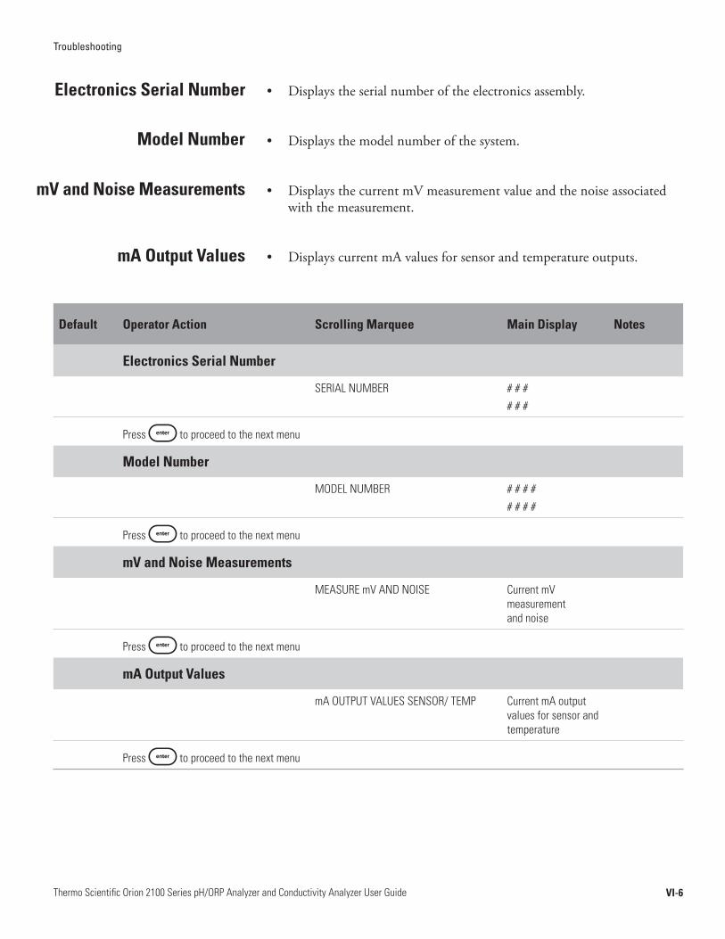
Troubleshooting
VI-6Thermo Scientific Orion 2100 Series pH/ORP Analyzer and Conductivity Analyzer User Guide
• Displaystheserialnumberoftheelectronicsassembly.
• Displaysthemodelnumberofthesystem.
• DisplaysthecurrentmVmeasurementvalueandthenoiseassociatedwiththemeasurement.
• DisplayscurrentmAvaluesforsensorandtemperatureoutputs.
Electronics Serial Number
Model Number
mV and Noise Measurements
mA Output Values
Default Operator Action Scrolling Marquee Main Display Notes
Electronics Serial Number
SERIAL NUMBER # # ## # #
Press to proceed to the next menu
Model Number
MODEL NUMBER # # # ## # # #
Press to proceed to the next menu
mV and Noise Measurements
MEASURE mV AND NOISE Current mV measurement and noise
Press to proceed to the next menu
mA Output Values
mA OUTPUT VALUES SENSOR/ TEMP Current mA output values for sensor and temperature
Press to proceed to the next menu
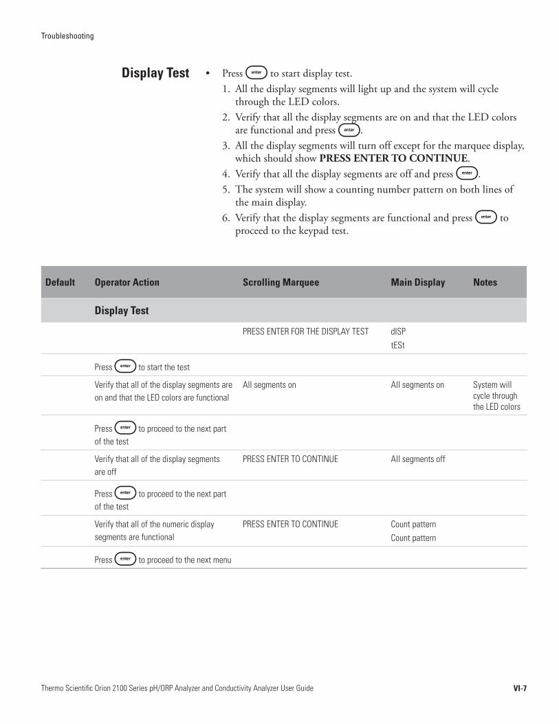
Troubleshooting
VI-7Thermo Scientific Orion 2100 Series pH/ORP Analyzer and Conductivity Analyzer User Guide
• Press tostartdisplaytest.1. Allthedisplaysegmentswilllightupandthesystemwillcycle
throughtheLEDcolors.2. VerifythatallthedisplaysegmentsareonandthattheLEDcolors
arefunctionalandpress .3. Allthedisplaysegmentswillturnoffexceptforthemarqueedisplay,
whichshouldshowPRESS ENTER TO CONTINUE.4. Verifythatallthedisplaysegmentsareoffandpress .5. Thesystemwillshowacountingnumberpatternonbothlinesof
themaindisplay.6. Verifythatthedisplaysegmentsarefunctionalandpress to
proceedtothekeypadtest.
Display Test
Default Operator Action Scrolling Marquee Main Display Notes
Display Test
PRESS ENTER FOR THE DISPLAY TEST dISPtESt
Press to start the test
Verify that all of the display segments are on and that the LED colors are functional
All segments on All segments on System will cycle through the LED colors
Press to proceed to the next part of the test
Verify that all of the display segments are off
PRESS ENTER TO CONTINUE All segments off
Press to proceed to the next part of the test
Verify that all of the numeric display segments are functional
PRESS ENTER TO CONTINUE Count patternCount pattern
Press to proceed to the next menu

Troubleshooting
VI-8Thermo Scientific Orion 2100 Series pH/ORP Analyzer and Conductivity Analyzer User Guide
• Themaindisplaywillshow0andtheMarqueewilldisplayKEYPAD TEST PRESS ALL KEYS ONE AT A TIME.
• Pressalleightkeysoneatatimeinanyorder.
* AfterthefirstkeyispressedErrorE033willbedisplayedifanewkeyisnotpressedwithin10seconds.
Keypad Test
Default Operator Action Scrolling Marquee Main Display Notes
Keypad Test
KEYPAD TEST PRESS ALL KEYS ONE AT A TIME
0
Press all keys one at a time in any order KEYPAD TEST PRESS ALL KEYS ONE AT A TIME
Display will show numbers 1 through 8 as keys are pressed
After the first key is pressed error E033 will be displayed if a new key is not pressed within 10 seconds
No operator action needed
The system will enter the measure mode if the keypad test is passed
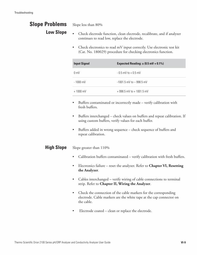
Troubleshooting
VI-9Thermo Scientific Orion 2100 Series pH/ORP Analyzer and Conductivity Analyzer User Guide
Slopelessthan80%
• Checkelectrodefunction,cleanelectrode,recalibrate,andifanalyzercontinuestoreadlow,replacetheelectrode.
• CheckelectronicstoreadmVinputcorrectly.Useelectronictestkit(Cat.No.180029)procedureforcheckingelectronicsfunction.
Input Signal Expected Reading: ± (0.5 mV + 0.1%)
0 mV - 0.5 mV to + 0.5 mV
- 1000 mV -1001.5 mV to – 998.5 mV
+ 1000 mV + 998.5 mV to + 1001.5 mV
• Bufferscontaminatedorincorrectlymade–verifycalibrationwithfreshbuffers.
• Buffersinterchanged–checkvaluesonbuffersandrepeatcalibration.Ifusingcustombuffers,verifyvaluesforeachbuffer.
• Buffersaddedinwrongsequence–checksequenceofbuffersandrepeatcalibration.
Slopegreaterthan110%
• Calibrationbufferscontaminated–verifycalibrationwithfreshbuffers.
• Electronicsfailure–resettheanalyzer.RefertoChapter VI, Resetting the Analyzer.
• Cablesinterchanged–verifywiringofcableconnectionstoterminalstrip.RefertoChapter II, Wiring the Analyzer.
• Checktheconnectionofthecablemarkersforthecorrespondingelectrode.Cablemarkersarethewhitetapeatthecapconnectoronthecable.
• Electrodecoated–cleanorreplacetheelectrode.
Slope ProblemsLow Slope
High Slope

Troubleshooting
VI-10Thermo Scientific Orion 2100 Series pH/ORP Analyzer and Conductivity Analyzer User Guide
• Checkconductivityprobefunction,cleanprobe,recalibrate,andifanalyzercontinuestoreadlow,replacetheprobe.
• Ifusingtheautomaticcalibrationfeature,100μS/cm,1413μS/cmand/or12.9mS/cmconductivitystandardsmustbeusedandthenominalcellconstantoftheconductivityprobemustbeenteredinthesetupmode.Fortheanalyzertorecognizetheconductivitystandard,enterthenominalcellconstantoftheconductivityprobethatisattachedtotheanalyzer(usually0.1cm-1,0.475cm-1or1.0cm-1).
Note: Fortheanalyzertorecognizetheconductivitystandard,theenteredcellconstantmustbeaccuratewithinafactorof3.Forexample,iftheenterednominalcellconstantis1.0cm-1,theactualcellconstantoftheconductivityprobemustbeintherangeof0.3cm-1to3.0cm-1toallowtheanalyzertoidentifytheconductivitystandardandperformtheautomaticcalibration.
• Ifusingconductivitystandardswithvaluesotherthan100μS/cm,1413μS/cmand/or12.9mS/cm,usethemanualcalibrationfeature.
• CheckelectronicstoreadmVinputcorrectly.Useelectronictestkit(Cat.No.180029)procedureforcheckingelectronicsfunction.
Input Signal Expected Reading: ± (0.5 mV + 0.1%)
0 mV - 0.5 mV to + 0.5 mV
- 1000 mV -1001.5 mV to – 998.5 mV
+ 1000 mV + 998.5 mV to + 1001.5 mV
• Conductivitystandardscontaminatedorincorrectlymade–verifycalibrationwithfreshstandards.
• Conductivitystandardsinterchanged–checkvaluesonstandardsandrepeatcalibration.
• Conductivitystandardsaddedinwrongsequence–checksequenceofstandardsandrepeatcalibration.
Cell Constant Problems
Automatic Standard Recognition Failure

Troubleshooting
VI-11Thermo Scientific Orion 2100 Series pH/ORP Analyzer and Conductivity Analyzer User Guide
Malfunction Possible Cause Remedy
Noisy Blocked reference junction on pH electrode
Make sure electrolyte is flowing properly.
pH electrode or conductivity probe failure
Check the cable connection and location of wiring to terminal strip. Refer to Chapter II.
Temperature probe failure Disconnect ATC. Temperature should read 25 °C (E101). Replace if necessary.
Faulty electrode cables Replace electrode cables.
Excessive Drift Sample concentration varying
Check sample status
Blocked reference junction on pH electrode
Make sure electrolyte is flowing properly.
pH electrode or conductivity probe failure
Check the cable connection and location of wiring to terminal strip. Refer to Chapter II.
Temperature probe failure Disconnect ATC. Temperature should read 25 °C (E101). Replace if necessary.
Does Not Calibrate Properly
Contaminated buffers or standards
Use new buffers or standard solutions.
Buffers or standards interchanged
Repeat calibration using buffers or standards in the correct sequence.
Temperature probe failure Disconnect ATC. Temperature should read 25 °C (E101). Replace if necessary.
Electronics failure or bad setup
Reset the analyzer. Refer to Chapter VI.
High Readings Analyzer out of calibration Recalibrate the analyzer. Refer to Chapter IV.
Over-Range Readings
Electrode connections loose or bad
Verify the electrode connections to the electrode cables.
Electrode wiring Electrodes not properly wired to terminal strip. Refer to Chapter II.
Blocked reference junction on pH electrode
Make sure electrolyte is flowing properly.
Electrode or probe failure Electrode or probe is shorted, cracked or damaged. Install a new electrode or probe. Refer to Chapter II.
Electronics failure or bad setup
Reset the analyzer. Refer to Chapter VI.
Analyzer out of calibration Recalibrate the analyzer. Refer to Chapter IV.
Low Readings Analyzer out of calibration Recalibrate the analyzer. Refer to Chapter IV.
Electronics failure Try resetting the analyzer. Refer to Chapter VI or consult Technical Support.
Default Battery failure Consult Technical Support.
Electronics failure Reset the analyzer. Refer to Chapter VI.
Troubleshooting Matrix
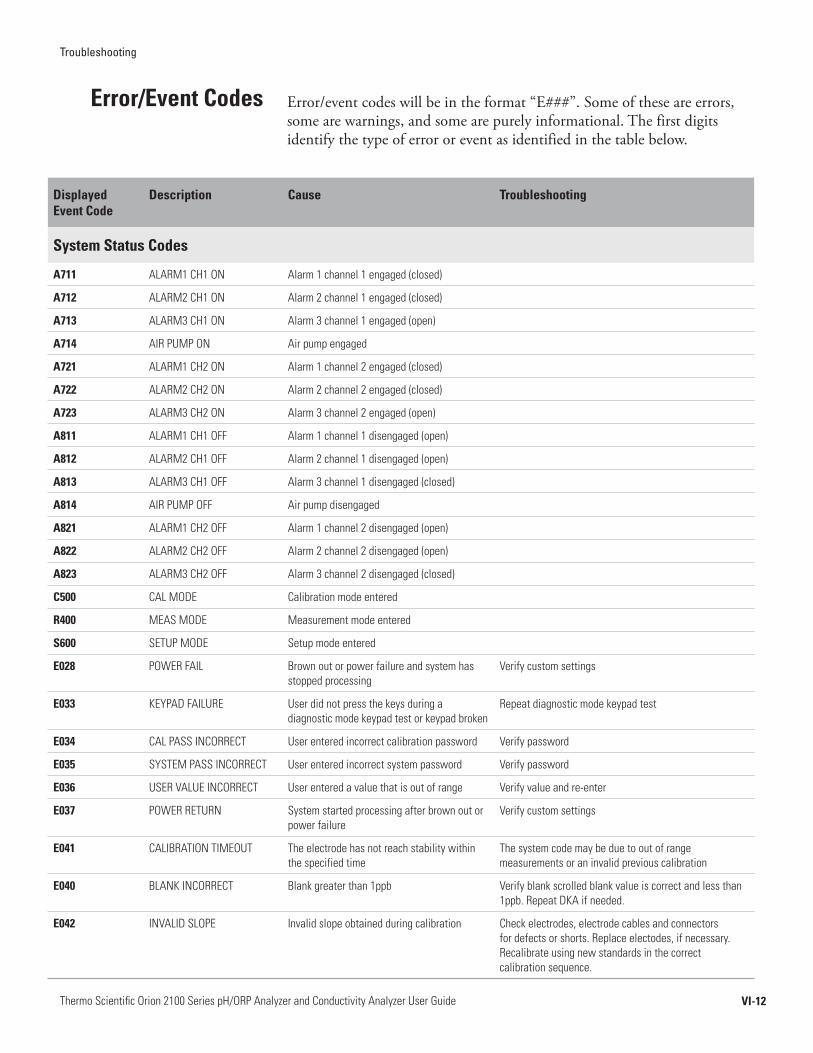
Troubleshooting
VI-12Thermo Scientific Orion 2100 Series pH/ORP Analyzer and Conductivity Analyzer User Guide
Error/eventcodeswillbeintheformat“E###”.Someoftheseareerrors,somearewarnings,andsomearepurelyinformational.Thefirstdigitsidentifythetypeoferrororeventasidentifiedinthetablebelow.
Error/Event Codes
Displayed Event Code
Description Cause Troubleshooting
System Status Codes
A711 ALARM1 CH1 ON Alarm 1 channel 1 engaged (closed)
A712 ALARM2 CH1 ON Alarm 2 channel 1 engaged (closed)
A713 ALARM3 CH1 ON Alarm 3 channel 1 engaged (open)
A714 AIR PUMP ON Air pump engaged
A721 ALARM1 CH2 ON Alarm 1 channel 2 engaged (closed)
A722 ALARM2 CH2 ON Alarm 2 channel 2 engaged (closed)
A723 ALARM3 CH2 ON Alarm 3 channel 2 engaged (open)
A811 ALARM1 CH1 OFF Alarm 1 channel 1 disengaged (open)
A812 ALARM2 CH1 OFF Alarm 2 channel 1 disengaged (open)
A813 ALARM3 CH1 OFF Alarm 3 channel 1 disengaged (closed)
A814 AIR PUMP OFF Air pump disengaged
A821 ALARM1 CH2 OFF Alarm 1 channel 2 disengaged (open)
A822 ALARM2 CH2 OFF Alarm 2 channel 2 disengaged (open)
A823 ALARM3 CH2 OFF Alarm 3 channel 2 disengaged (closed)
C500 CAL MODE Calibration mode entered
R400 MEAS MODE Measurement mode entered
S600 SETUP MODE Setup mode entered
E028 POWER FAIL Brown out or power failure and system has stopped processing
Verify custom settings
E033 KEYPAD FAILURE User did not press the keys during a diagnostic mode keypad test or keypad broken
Repeat diagnostic mode keypad test
E034 CAL PASS INCORRECT User entered incorrect calibration password Verify password
E035 SYSTEM PASS INCORRECT User entered incorrect system password Verify password
E036 USER VALUE INCORRECT User entered a value that is out of range Verify value and re-enter
E037 POWER RETURN System started processing after brown out or power failure
Verify custom settings
E041 CALIBRATION TIMEOUT The electrode has not reach stability within the specified time
The system code may be due to out of range measurements or an invalid previous calibration
E040 BLANK INCORRECT Blank greater than 1ppb Verify blank scrolled blank value is correct and less than 1ppb. Repeat DKA if needed.
E042 INVALID SLOPE Invalid slope obtained during calibration Check electrodes, electrode cables and connectors for defects or shorts. Replace electodes, if necessary. Recalibrate using new standards in the correct calibration sequence.

Troubleshooting
VI-13Thermo Scientific Orion 2100 Series pH/ORP Analyzer and Conductivity Analyzer User Guide
Displayed Event Code
Description Cause Troubleshooting
System Event/Error Codes - Yellow LED
E004 DEFAULT VALUES Analyzer has been reset or is new out of box
Calibrate the analyzer
E021 HARDWARE FAULT System error Contact Technical Support 1-800-225-1480
E101 CH1 TEMP OUT OF RANGE Temperature sensor on channel 1 out of range (5 ˚C to 45 ˚C) for ISE
Check ATC cable and probe connections. Replace if needed.
E102 CH2 TEMP OUT OF RANGE Temperature sensor on channel 2 out of range (5 ˚C to 45 ˚C) for ISE
Check ATC cable and probe connections. Replace if needed.
E111 CH1 CAL DUE User calibration required on channel 1. No calibration has been performed in user specified time interval.
Recalibrate the analyzer.
E112 CH2 CAL DUE User calibration required on channel 2. No calibration has been performed in user specified time interval.
Recalibrate the analyzer.
E127 CH1 SOUT mA OVER RANGE Measured sensor value above Sout high limit value on channel 1
Verify user selectable Sout high limit value in setup mode
E128 CH1 SOUT mA UNDER RANGE Measured sensor value below Sout low limit value on channel 1
Verify user selectable Sout low limit value in setup mode
E129 CH1 TOUT mA OVER RANGE Measured temperature value above Tout high limit value on channel 1
Verify user selectable Tout high limit value in setup mode
E130 CH1 TOUT mA UNDER RANGE Measured temperature value below Tout low limit value on channel 1
Verify user selectable Tout low limit value in setup mode
E131 CH2 SOUT mA OVER RANGE Measured sensor value above Sout high limit value on channel 2
Verify user selectable Sout high limit value in setup mode
E132 CH2 SOUT mA UNDER RANGE Measured sensor value below Sout low limit value on channel 2
Verify user selectable Sout low limit value in setup mode
E133 CH2 TOUT mA OVER RANGE Measured temperature value above Tout high limit value on channel 2
Verify user selectable Tout high limit value in setup mode
E134 CH2 TOUT mA UNDER RANGE Measured temperature value below Tout low limit value on channel 2
Verify user selectable Tout low limit value in setup mode

Troubleshooting
VI-14Thermo Scientific Orion 2100 Series pH/ORP Analyzer and Conductivity Analyzer User Guide
Displayed Event Code
Description Cause Troubleshooting
System Error Codes - Red LED
E001 HARDWARE FAULT System error Contact Technical Support 1-800-225-1480
E002 HARDWARE FAULT System error Contact Technical Support 1-800-225-1480
E018 HARDWARE FAULT System error Contact Technical Support 1-800-225-1480
E019 HARDWARE FAULT System error Contact Technical Support 1-800-225-1480
E020 HARDWARE FAULT System error Contact Technical Support 1-800-225-1480
E024 HARDWARE FAULT System error Contact Technical Support 1-800-225-1480
E026 HARDWARE FAULT System error Contact Technical Support 1-800-225-1480
E027 HARDWARE FAULT System error Contact Technical Support 1-800-225-1480
E029 HARDWARE FAULT System error Contact Technical Support 1-800-225-1480
E030 HARDWARE FAULT System error Contact Technical Support 1-800-225-1480
E038 HARDWARE FAULT System error Contact Technical Support 1-800-225-1480
E103 CH1 MEAS OVER RANGE Measurement is over range on channel 1, the display should also be flashing ‘9999’
Check if electrode is not connected, electrode cables are faulty or electrode junction is fouled
E104 CH2 MEAS OVER RANGE Measurement is over range on channel 2, the display should also be flashing ‘9999’
Check if electrode is not connected, electrode cables are faulty or electrode junction is fouled
E109 CH1 BAD SLOPE Last calibration produced a bad slope on channel 1. Slope is less than 45 mV/decade or more than 62 mV/decade or the calibration standards may have been interchanged.
Recalibrate the analyzer using fresh standards. Recalibrate using the correct sequence of standards.
E110 CH2 BAD SLOPE Last calibration produced a bad slope on channel 2. Slope is less than 45 mV/decade or more than 62 mV/decade or the calibration standards may have been interchanged.
Recalibrate the analyzer using fresh standards. Recalibrate using the correct sequence of standards.
E113 CH1 CAL OVERDUE Calibration is overdue on channel 1 by more than 50% of the user specified time interval
Recalibrate the analyzer
E113 CH2 CAL OVERDUE Calibration is overdue on channel 2 by more than 50% of the user specified time interval
Recalibrate the analyzer
E121 CH1 TEMP BROKEN Temperature sensor on channel 1 broken or out of range
Check ATC cable connections and probe for damage. Replace if needed.
E122 CH2 TEMP BROKEN Temperature sensor on channel 2 broken or out of range
Check ATC cable connections and probe for damage. Replace if needed.
E125 CH1 BAD OFFSET Last calibration produced a bad Eo offset on channel 1
Recalibrate the analyzer using fresh standards. Check electrode connections. Replace electrode, if needed.
E126 CH2 BAD OFFSET Last calibration produced a bad Eo offset on channel 2
Recalibrate the analyzer using fresh standards. Check electrode connections. Replace electrode, if needed.
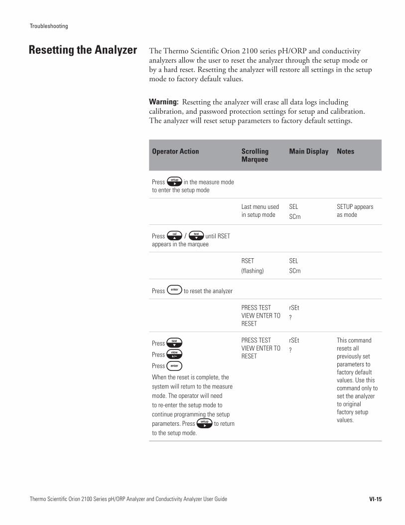
Troubleshooting
VI-15Thermo Scientific Orion 2100 Series pH/ORP Analyzer and Conductivity Analyzer User Guide
TheThermoScientificOrion2100seriespH/ORPandconductivityanalyzersallowtheusertoresettheanalyzerthroughthesetupmodeorbyahardreset.Resettingtheanalyzerwillrestoreallsettingsinthesetupmodetofactorydefaultvalues.
Warning: Resettingtheanalyzerwillerasealldatalogsincludingcalibration,andpasswordprotectionsettingsforsetupandcalibration.Theanalyzerwillresetsetupparameterstofactorydefaultsettings.
Operator Action Scrolling Marquee
Main Display Notes
Press in the measure mode to enter the setup mode
Last menu used in setup mode
SELSCrn
SETUP appears as mode
Press / until RSET appears in the marquee
RSET(flashing)
SELSCrn
Press to reset the analyzer
PRESS TEST VIEW ENTER TO RESET
rSEt?
Press
Press
Press
When the reset is complete, the system will return to the measure mode. The operator will need to re-enter the setup mode to continue programming the setup parameters. Press to return to the setup mode.
PRESS TEST VIEW ENTER TO RESET
rSEt?
This command resets all previously set parameters to factory default values. Use this command only to set the analyzer to original factory setup values.
Resetting the Analyzer

Troubleshooting
VI-16Thermo Scientific Orion 2100 Series pH/ORP Analyzer and Conductivity Analyzer User Guide
Ahardresetshouldbeperformediftheanalyzerbecomesunresponsiveorthestatusindicatorsareflashing.Performthefollowingsequence:
• Carefullyopenthefrontcoveroftheelectronicscase(loosenthe4cornerscrews).
• PressthesmallbuttonlocatedontheraisedportionofthePCBtoresettheelectronics.
• Closethefrontcoveroftheelectronicscaseandtightenthescrews.
Systemsettingsandcalibrationsarepreservedandanalyzerreturnstothemeasuremode.Theactualvalueforconcentrationandtemperaturewillbedisplayediftheelectrodesareproperlyinstalled.Ifthesystemdoesnotreset,contactTechnicalSupportat1-800-225-1480forassistance.
Intheeventyourequiretechnicalassistance,pleasehavetheserialnumberavailablewhencallingforassistancealongwiththesoftwareversion.
• Theanalyzerserialnumberislocatedontheundersideoftheelectronicsenclosureorifpanelmountedthenonthebacksideoftheelectronicsenclosure.
• Thesoftwarerevisionisaccessedthroughthediagnosticsmode.
Hard Reset
Serial Number and Software Revision
Troubleshooting
VI-17Thermo Scientific Orion 2100 Series pH/ORP Analyzer and Conductivity Analyzer User Guide
Service and RepairExtended Warranty
TheThermoScientificOrion2100seriespH/ORPandconductivityanalyzersprovidemeasurementsthroughacombinationofourpremiumelectrodetechnologyanduserfriendlyscrollingmarqueetosetanewindustrystandardforreliability.Similarly,ThermoFisherScientificnowoffersmultiplelevelsofserviceprogramstomeetyourneedsbeyondtheOne-YearProductWarrantyperiod.
Acosteffectivewaytoblendyourin-houseexpertisewithourserviceandsupportexperts,togetthesupportyouneedataspecifiedannualcontractedprice.Thiswarrantyplanmustbepurchasedwithinninetydaysoftheinitialproductpurchasedate.
• ExtendsthefeaturesofthestandardOne-YearProductWarrantyforasecondorthirdyear.
• Providesaccesstothemanufacturer’stechnicalexpertsatThermoScientificOrionSupportCallCenter,1-800-225-1480,MondaythroughFriday,8:00AM–5:00PMEST.
• Aftertelephoneconsultation,wewillsendyourequiredpartsforinstallationbyyouron-sitetechnician.
Within-houseresourcesatapremium,manyorganizationsrequireimmediateaccesstomanufacturerexpertise.Purchaseaservicekitwithinninetydaysoftheinitialproductpurchasedatetoeliminatethecostlyeffectsofdowntime.
• Providesacontracted,cost-effectivemeanstoenhancelevelofsupportofferedduringtheproductwarrantyperiod.
• Providespriorityaccesstothemanufacturer’stechnicalexpertsatThermoScientificOrionSupportCallCenter.
• Providesaservicekittoexpediteon-siterepairsinconjunctionwithtelephoneconsultationwithThermoScientificOrionproductexperts.
Theservicekitincludes:• Powersupply• Frontpaneldisplay• Electrodecables
Service Kit to Expand Standard Warranty
Troubleshooting
VI-18Thermo Scientific Orion 2100 Series pH/ORP Analyzer and Conductivity Analyzer User Guide
Whendown-timeisacostfactortobestrictlycontrolled,theadvancedreplacementserviceplanisoftentimesthebestchoice.
• EnhanceslevelofsupportofferedduringthestandardOne-YearProductWarranty.
• Providesaccesstothemanufacturer’stechnicalexpertsatThermoScientificOrionSupportCallCenterandrepairfacilities.
• If,afterreasonableremotediagnosticsandtrouble-shootingattempts,wedeterminetheanalyzertobenon-functioning,wewillmakeallreasonableefforttogetrequiredpartsorequipmentouttoyourfacilitybythefollowingdayforinstallationbyyouron-sitetechnician.
• Offerspredictableexpenditurethroughfixedannualcontractprice.
AskyourThermoScientificOrionproductssalesrepresentativetoputyouintouchwiththeserviceplanmanager.Wehaveadditionalserviceoptionsthataresuretoaddressyourconcerns.
Tohelpyouachieveoptimumperformance,relyonustoprovideyouwithanefficientandqualityinstallationandthestart-upsupportyouneedtobeupandrunningquickly.Ourservicerepresentativesarehighlytrained,experienced,andcertifiedforyourproductandwillbetheretomakesurethatyourinstrumentationdeliverstospecifications.
Thisisaone-dayserviceengineeron-sitevisittoyourfacilityforremedialserviceeventsatstandardresponsetime.Considerthisplananexcellentuplifttooneoftheaforementionedprograms.
Allprecision-madescientificequipmentrequirespreventivemaintenanceandcalibrationcheckstoperformattheirmaximumeffectiveness.Considerafixed-feepreventivemaintenancecontracttohaveoneofourexpertsperformthefollowingtasks:• Samplingcheck• Fullvalidationtest• Visualcheckforworn,looseordamagedparts• Replacementofconsumables(additionalchargeforconsumables)• Diagnosticchecktoverifyalloperatingparametersarewithinthe
factoryspecifications• Checkanalyzerelectrodes,flowsandpressures• Cleanandreplaceanywearableitems
Advanced Replacement
Not sure which plan is best for you?
Installation and Start-Up
Remedial Service
Preventive Maintenance Programs
VII-1Thermo Scientific Orion 2100 Series pH/ORP Analyzer and Conductivity Analyzer User Guide
Chapter VII Customer Service
This equipment generates, uses and can radiate radio frequency energy and if not installed and used in accordance with the user guide, may cause interference to radio communications. It has been tested and found to comply with the limits for a Class A computing device pursuant to Subpart J of Part 15 of FCC Rules, which are designed to provide reasonable protection against such interference when operated in a commercial environment. Operation of this equipment in a residential area is likely to cause interference in which case the user, at his own expense, will be required to take whatever measure may be required to correct the interference.
“This digital apparatus does not exceed the (Class A) limits for radio noise emissions from digital apparatus set out in the Radio Interference Regulations of the Canadian Department of Communications.”
“Le présent appareil numérique n’émet pas de bruits radioélectriques dépassant les limites applicables aux appareils numériques (de la class A) prescrites dans le Régiement sur le brouillage radioélectrique édicté par le ministère des Communications du Canada.”
This product is required to comply with the European Union’s Waste Electrical & Electronic Equipment (WEEE) Directive 2002/96/EC . It is marked with the following symbol:
Thermo Fisher Scientific has contracted with one or more recycling/disposal companies in each EU Member State and this product should be disposed of or recycled through them. Further information on compliance with these directives, the recyclers in your country, and information on Thermo Scientific Orion products that may assist the detection of substances subject to the RoHS Directive are available at www.thermo.com/WEEERoHS.
Notice of Compliance
WEEE Compliance
VII-2
Customer Service
Thermo Scientific Orion 2100 Series pH/ORP Analyzer and Conductivity Analyzer User Guide
Manufacturer:
Thermo Fisher Scientific Inc. 166 Cummings Center Beverly, MA 01915 USA
Hereby declares that the following products:
Model 2102PH pH/ORP Analyzer
Model 2104CD Conductivity Analyzer
Conform with the following directives and standards:
Safety: Low Voltage Directive (LVD), 73/23/EEC
EN61010-1:2001, Safety requirements for electrical equipment for measurement, control and laboratory use – general requirements
EMC: Electromagnetic Compatibility (EMC), 89/336/EEC
EN 61326-1:2006, Electrical equipment for measurement, control and laboratory use
These products have been manufactured in compliance with the provisions of the relevant manufacturing and test documents and processes. These documents and processes are recognized as complying with ISO 9001:2008 by QMI, listed as File #001911.
Patrick Chiu Place and Date of Issue: Senior Quality Engineer, Beverly, MA Regulatory Compliance June 16, 2009
Declaration of Conformity
VII-3
Customer Service
Thermo Scientific Orion 2100 Series pH/ORP Analyzer and Conductivity Analyzer User Guide
For products not listed in this warranty statement, please visit our website at www.thermo.com/processwater.
For updated contact information, visit www.thermo.com/contactwater.
Thermo Fisher Scientific Inc. 166 Cummings Center Beverly, MA 01915 Toll Free: 800-225-1480 Tel: 978-232-6000 Dom. Fax: 978-232-6015 Int’l Fax: 978-232-6031
The minimum order requirement is $100 for Thermo Scientific Orion process products. An order is considered to be a purchase order for products to be shipped to a single location. International minimum order requirements may vary. Contact your international coordinator for details.
For customers in the U.S., rush orders received before 12 pm Eastern Time will be shipped the same day. Rush orders received after 12 noon Eastern Time will be shipped the next business day.
For customers and dealers in Canada, rush orders will be shipped within 2 business days. For customers and dealers outside the U.S. and Canada, contact your international coordinator for rush order scheduling. All rush orders carry a $50 incremental charge per order. FOB: Beverly. Freight charges are prepaid and added or freight collect. All rush order processing is subject to stock availability.
Permission to return Thermo Scientific Orion products must be obtained prior to return. Contact us within 30 days of receipt of goods for a return authorization number.
Terms and Conditions
Minimum Order
Rush Orders
Returning Goods
Contact Information

VII-4
Customer Service
Thermo Scientific Orion 2100 Series pH/ORP Analyzer and Conductivity Analyzer User Guide
Some materials are designated corrosive/oxidizer by DOT and IATA. Some materials may require special labeling and handling. Carriers may add additional freight charges for handling/transporting these materials. Consolidating such material with other products may be prohibited. Additional freight charges are billed to you per FOB terms. Advise manufacturer of shipping instructions for these hazardous materials to reduce your freight costs.
Permission to return new, excess inventory must be obtained prior to return. If any item is authorized to be returned for credit as a result of an incorrect purchase without a reorder, a 25% restocking charge of the price paid for the product will be made. International customer’s restocking fee of 25% will be off the international price.
Only new (in the box) goods may be returned within 30 days of shipment from manufacturer. Older items, 9 digit parts and discontinued items cannot be returned for credit.
Manufacturer must be notified within 30 days of receipt of invoice of any item or billing discrepancies. All substantiated claims will be remedied by a credit memo and a new order placed for short shipment. Any shipment discrepancy claimed after 30 days of invoice date will not be honored and credit will not be issued by manufacturer.
Manufacturer shall not be liable for failure to perform or for delay in performance due to fire, flood, strike, or other labor difficulty, act of God, act of any governmental authority or of the purchaser, riot, embargo, fuel or energy shortage, wrecks or delays in transportation, inability to obtain necessary labor, materials, or manufacturing facilities from usual sources, or due to any cause beyond its reasonable control. In the event of a delay in performance due to any such cause, the date of delivery or time for completion of performance will be extended by a period of time reasonably necessary to overcome the effect of such delay.
Restocking Charge
Short Shipments
Force Majeure
Hazardous Materials

VII-5
Customer Service
Thermo Scientific Orion 2100 Series pH/ORP Analyzer and Conductivity Analyzer User Guide
Thermo Scientific Orion process products are warranted to be free from defects in material and workmanship for a period of 12 months from date of installation or 18 months from date of shipment, whichever is earlier, when used under normal operating conditions and in accordance with the operating limitations and maintenance procedures given in the user guide and when not having been subjected to accident, alteration, misuse or abuse. This warranty is also conditioned upon expendable and consumable items (diffusion tubing, electrodes and all solutions) being stored at temperatures between 5 °C and 45 °C (40 °F and 110 °F) in a non-corrosive atmosphere and within the shelf life printed on the product.
In the event of failure within the warranty period, the manufacturer or its authorized dealer will, at the option of manufacturer, repair or replace the product nonconforming to the above warranty or will refund the purchase price of the product.
The warranty described is exclusive and in lieu of all other warranties whether statutory, express, or implied including, but not limited to, any implied warranty of merchantability or fitness for a particular purpose and all warranties arising from the course of dealing or usage of trade. The buyer’s sole and exclusive remedy is for repair or replacement of the non-conforming part thereof, or refund of the purchase price, but in no event shall the manufacturer (its contractors and suppliers of any tier) be liable to the buyer or any person for any special indirect, incidental, or consequential damages whether the claims are used in contract, in tort (including negligence), or otherwise with respect to or arising out of the product furnished hereunder.
Process products used at overseas nuclear facilities are also subject to the manufacturer’s nuclear terms and conditions. Contact the manufacturer if you do not have a copy.
Representations and warranties made by any person, including its authorized dealers, distributors, representatives, and employees of the manufacturer, which are inconsistent or in addition to the terms of this warranty shall not be binding upon manufacturer unless in writing and signed by one of its officers.
Warranty

A-1Thermo Scientific Orion 2100 Series pH/ORP Analyzer and Conductivity Analyzer User Guide
Appendix
pH/ORP
E0 default: 0.0 mV
Slope default: 100 % (59.15 mV/decade)
Slope range: 80 % to 110 % (47.3 mV/decade to 65.1 mV/decade)
CISO: 7
Conductivity
Cell constant default: 0.1 cm-1
Default Values
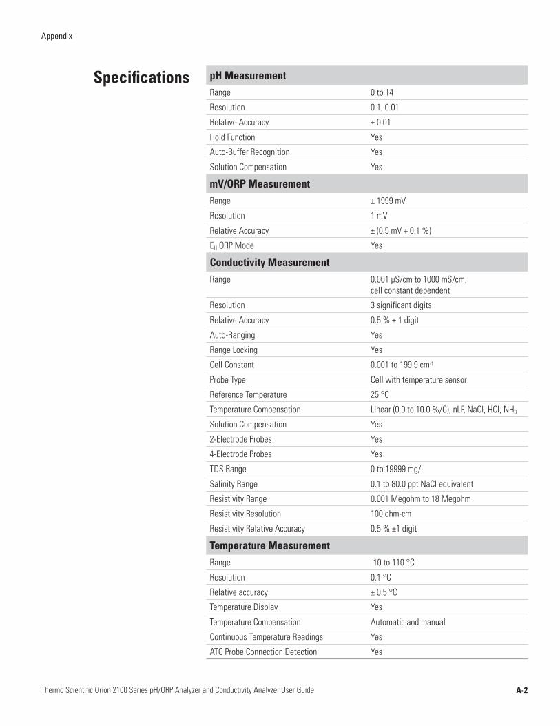
A-2Thermo Scientific Orion 2100 Series pH/ORP Analyzer and Conductivity Analyzer User Guide
Appendix
pH MeasurementRange 0 to 14
Resolution 0.1, 0.01
Relative Accuracy ± 0.01
Hold Function Yes
Auto-Buffer Recognition Yes
Solution Compensation Yes
mV/ORP MeasurementRange ± 1999 mV
Resolution 1 mV
Relative Accuracy ± (0.5 mV + 0.1 %)
EH ORP Mode Yes
Conductivity MeasurementRange 0.001 µS/cm to 1000 mS/cm,
cell constant dependent
Resolution 3 significant digits
Relative Accuracy 0.5 % ± 1 digit
Auto-Ranging Yes
Range Locking Yes
Cell Constant 0.001 to 199.9 cm-1
Probe Type Cell with temperature sensor
Reference Temperature 25 °C
Temperature Compensation Linear (0.0 to 10.0 %/C), nLF, NaCl, HCl, NH3
Solution Compensation Yes
2-Electrode Probes Yes
4-Electrode Probes Yes
TDS Range 0 to 19999 mg/L
Salinity Range 0.1 to 80.0 ppt NaCl equivalent
Resistivity Range 0.001 Megohm to 18 Megohm
Resistivity Resolution 100 ohm-cm
Resistivity Relative Accuracy 0.5 % ±1 digit
Temperature MeasurementRange -10 to 110 °C
Resolution 0.1 °C
Relative accuracy ± 0.5 °C
Temperature Display Yes
Temperature Compensation Automatic and manual
Continuous Temperature Readings Yes
ATC Probe Connection Detection Yes
Specifications
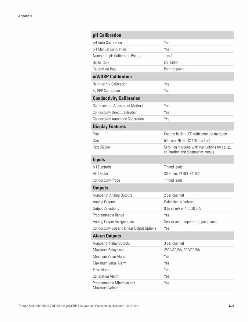
A-3Thermo Scientific Orion 2100 Series pH/ORP Analyzer and Conductivity Analyzer User Guide
Appendix
pH CalibrationpH Auto-Calibration Yes
pH Manual Calibration Yes
Number of pH Calibration Points 1 to 3
Buffer Sets US, EURO
Calibration Type Point to point
mV/ORP CalibrationRelative mV Calibration Yes
EH ORP Calibration Yes
Conductivity CalibrationCell Constant Adjustment Method Yes
Conductivity Direct Calibration Yes
Conductivity Automatic Calibration Yes
Display FeaturesType Custom backlit LCD with scrolling marquee
Size 54 mm x 76 mm (2 1/8 in x 3 in)
Text Display Scrolling marquee with instructions for setup, calibration and diagnostics menus
InputspH Electrode Tinned leads
ATC Probe 30 Kohm, PT100, PT1000
Conductivity Probe Tinned leads
OutputsNumber of Analog Outputs 2 per channel
Analog Outputs Galvanically isolated
Output Selections 0 to 20 mA or 4 to 20 mA
Programmable Range Yes
Analog Output Assignments Sensor and temperature, per channel
Conductivity Log and Linear Output Options Yes
Alarm OutputsNumber of Relay Outputs 3 per channel
Maximum Relay Load 250 VAC/5A, 30 VDC/5A
Minimum Value Alarm Yes
Maximum Value Alarm Yes
Error Alarm Yes
Calibration Alarm Yes
Programmable Minimum and Maximum Values
Yes
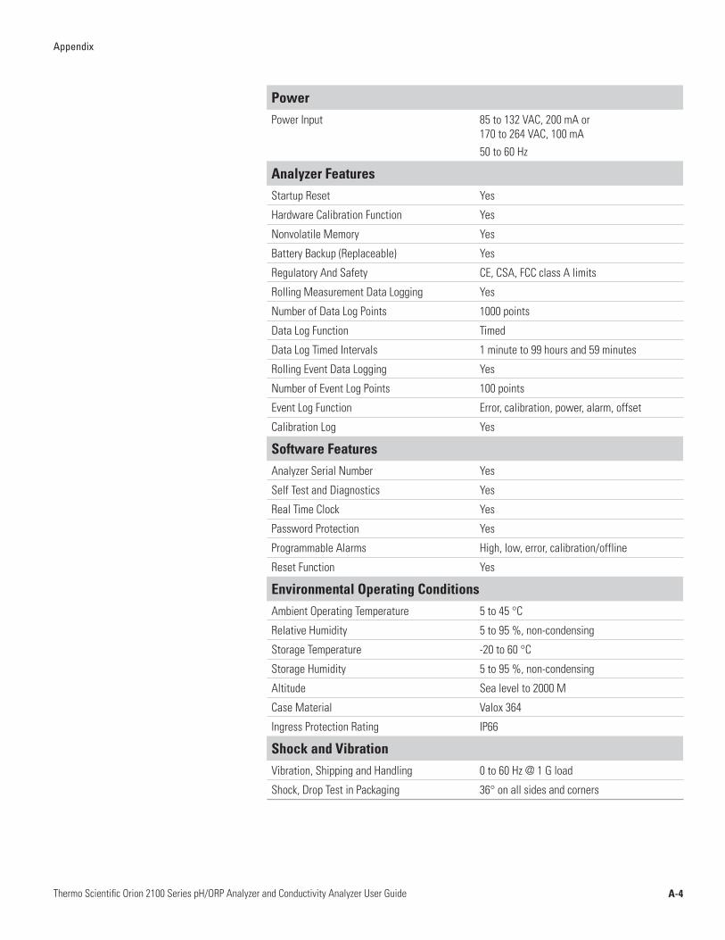
A-4Thermo Scientific Orion 2100 Series pH/ORP Analyzer and Conductivity Analyzer User Guide
Appendix
PowerPower Input 85 to 132 VAC, 200 mA or
170 to 264 VAC, 100 mA 50 to 60 Hz
Analyzer FeaturesStartup Reset Yes
Hardware Calibration Function Yes
Nonvolatile Memory Yes
Battery Backup (Replaceable) Yes
Regulatory And Safety CE, CSA, FCC class A limits
Rolling Measurement Data Logging Yes
Number of Data Log Points 1000 points
Data Log Function Timed
Data Log Timed Intervals 1 minute to 99 hours and 59 minutes
Rolling Event Data Logging Yes
Number of Event Log Points 100 points
Event Log Function Error, calibration, power, alarm, offset
Calibration Log Yes
Software FeaturesAnalyzer Serial Number Yes
Self Test and Diagnostics Yes
Real Time Clock Yes
Password Protection Yes
Programmable Alarms High, low, error, calibration/offline
Reset Function Yes
Environmental Operating ConditionsAmbient Operating Temperature 5 to 45 °C
Relative Humidity 5 to 95 %, non-condensing
Storage Temperature -20 to 60 °C
Storage Humidity 5 to 95 %, non-condensing
Altitude Sea level to 2000 M
Case Material Valox 364
Ingress Protection Rating IP66
Shock and VibrationVibration, Shipping and Handling 0 to 60 Hz @ 1 G load
Shock, Drop Test in Packaging 36° on all sides and corners

A-5Thermo Scientific Orion 2100 Series pH/ORP Analyzer and Conductivity Analyzer User Guide
Appendix
Cat. No. Description
2102PH 2102PH single channel pH/ORP analyzer only
2102PH1SC 2102PH single channel analyzer and ultra pure water (UPW) pH kit, includes flow cell, 2001SC ROSS® pH electrode, electrode cable (2001EC), ATC probe and buffers (pH 4, 7 and 10)
2102PH1X 2102PH single channel analyzer and ORP kit, includes ORP electrode (110250) and ORP standard (967901)
2102PH2 2102PH dual channel pH/ORP analyzer only
2102PH2SC 2102PH dual channel analyzer and ultra pure water (UPW) pH kit, includes (2) flow cells, (2) x 2001SC ROSS pH electrodes, (2) electrode cables (2001EC), (2) ATC probes and buffers (pH 4, 7 and 10)
2102PH2X 2102PH dual channel analyzer and ORP kit, includes (2) ORP electrodes (110250) and ORP standard (967901)
2104CD 2104CD single channel conductivity analyzer only
2104CD1SS 2104CD single channel analyzer and ultra pure water (UPW) conductivity kit, includes 2002SS conductivity cell, flow cell and 100 µS/cm conductivity standard (011008)
2104CD2 2104CD dual channel conductivity analyzer only
2104CD2SS 2104CD dual channel analyzer and ultra pure water (UPW) conductivity kit, includes (2) x 2002SS conductivity cells, (2) flow cells and 100 µS/cm conductivity standard (011008)
21PHCD2 2100 series dual channel pH/ORP and conductivity analyzer only
2100PH2 Second channel module for pH/ORP
2100CD2 Second channel module for conductivity
2001SC ROSS combination pH electrode with screw cap
2001EC 1 meter electrode cable for use with 2001SC electrode
20015M 5 meter electrode cable for use with 2001SC electrode
110250 ORP electrode with cable and unterminated ends
2002SS Stainless steel 2-electrode conductivity cell, 0.01 µS/cm to 300 µS/cm
2002CC Carbon 4-electrode conductivity cell, 10 µS/cm to 200 mS/cm
2100DC RS232C/485 digital communications
2001FC Flow cell for 2001SC ROSS pH electrode
2100FCA1 Flow cell adapter for 2100R series ROSS Ultra® industrial pH electrodes
2100FCA2 Flow cell adapter for 2002SS conductivity cell
2100AMP Pre-amp for 2100 series analyzers
2100SMK Sample panel mounting kit
2100PMK Pipe mounting kit
2100TM Automatic temperature compensation (ATC) probe, Pt1000, 5 meter cable
Ordering Information

A-6Thermo Scientific Orion 2100 Series pH/ORP Analyzer and Conductivity Analyzer User Guide
Appendix
Mounting Dimensions Note: All dimensions are in inches.
5.67
5.67
6.741.47
5.20
5.40
PANEL CUT-OUT
6.50
6.96
5.67
5.67
5.841.47
5.40
4.88
4.20 5.20
.55 .55
.40.26
.20
1.07
.75
.75
1.07
PANEL CUT OUT
Panel Mounting, Version 1
Panel Mounting, Version 2
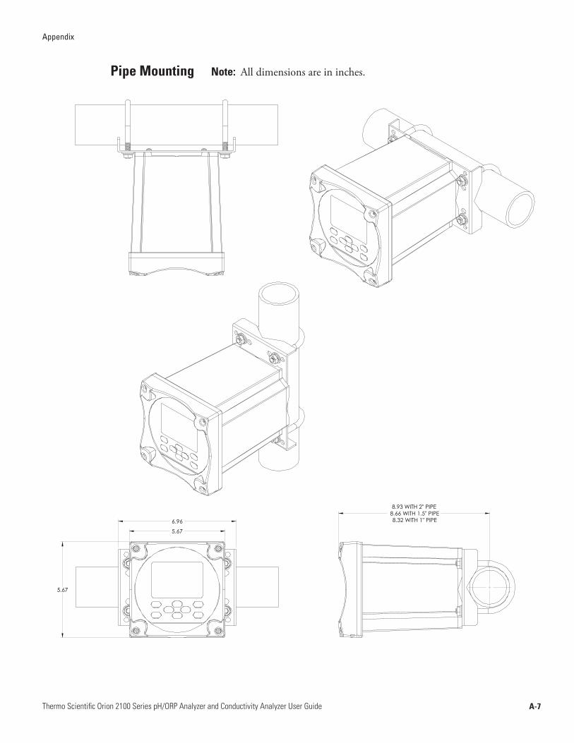
A-7Thermo Scientific Orion 2100 Series pH/ORP Analyzer and Conductivity Analyzer User Guide
Appendix
Pipe Mounting
5.67
5.67
6.96
8.93 WITH 2" PIPE8.66 WITH 1.5" PIPE8.32 WITH 1" PIPE
Note: All dimensions are in inches.
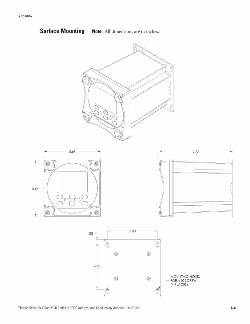
A-8Thermo Scientific Orion 2100 Series pH/ORP Analyzer and Conductivity Analyzer User Guide
Appendix
Surface Mounting
5.67
5.67
7.38
5.00
4.63
(4 PLACES)
MOUNTING HOLESFOR #10 SCREW
.35
Note: All dimensions are in inches.

263639-001 Rev. A 09-09
9 0 0 1 : 2 0 0 8
Process Water Instruments
North America 166 Cummings Center Beverly, MA 01915 USA Toll Free: 1-800-225-1480 Tel: 1-978-232-6000 Dom. Fax: 1-978-232-6015 Int’l Fax: 978-232-6031
EuropeP.O. Box 254, 3860 AG Nijkerk Wallerstraat 125K, 3862 CN Nijkerk, Netherlands Tel: (31) 033-2463887 Fax: (31) 033-2460832
Asia PacificBlk 55, Ayer Rajah Crescent #04-16/24, Singapore 139949 Tel: 65-6778-6876 Fax: 65-6773-0836
www.thermo.com/processwater
© 2009 Thermo Fisher Scientific Inc. All rights reserved.