Embed Size (px)
Citation preview

70331
750 MHz Mini-Bridger INSTALLATION AND OPERATIONINSTALLATION AND OPERATIONMANUALMANUAL

(This page intentionally left blank.)(This page intentionally left blank.)

750 MHz Mini-BridgerINSTALLATION AND OPERATIONINSTALLATION AND OPERATIONMANUALMANUAL
Data, drawings, and other materialcontained herein are proprietary toANTEC Network Technologies andmay not be reproduced or duplicatedin any form without the priorpermission of ANTEC NetworkTechnologies.
When ordering parts from ANTECNetwork Technologies, be sure toinclude the equipment model number,equipment serial number, and adescription of the part.
In all correspondence with ANTECNetwork Technologies regarding thispublication, please refer to:
70331First Edition – 6/98
© 1998 by ANTEC Network TechnologiesAll rights reserved. No part of this bookmay be reproduced in any form or byany means, without permission inwriting from ANTEC NetworkTechnologies.

(This page intentionally left blank.)(This page intentionally left blank.)

70331 FTMB Mini-Bridger Installation and Operation 1-1
Section 1General Information
Overview
Introduction This manual describes installation and operation of the FTMB Mini-Bridger.
ManualContents
This manual contains four sections.• Section 1 - General Information• Section 2 - Installation• Section 3 - Setup and Operation• Section 4 - Theory of Operation
How to Use thisManual
This manual is divided into the sections listed above. Major topics in eachsection are listed at the beginning of the section. Use these lists to find thedesired information.
In this Section This section contains these major topics.
Topic See PageOverview 1-1How to Contact ANTEC Network Technologies 1-2We Welcome Your Comments 1-3Safety 1-4Equipment Description 1-8Equipment Specifications 1-10List of Abbreviations 1-13
Section 1 - General Information
1-2 FTMB Mini-Bridger Installation and Operation 70331
How to Contact ANTEC Network Technologies
Overview ANTEC Network Technologies Customer Service and Technical Service areready to assist you as necessary.
How to ContactANTECNetworkTechnologies
Here’s how to contact us.
In the USA . . . Outside the USA . . .By phone, call 1-800-FIBERME andpress 2 for Technical Service
By mail, write to:ANTEC Network TechnologiesAttention: Technical Service11450 Technology CircleDuluth, GA 30097
Contact your ANTEC NetworkTechnologies sales office forassistance. Sales offices are listed onthe back cover of this manual.

Section 1 - General Information
70331 FTMB Mini-Bridger Installation and Operation 1-3
We Welcome Your Comments
Overview We welcome your comments on this manual. User comments are an importantsource of ideas to improve our manuals.
How toComment
By Mail . . . By E-mail:Complete the comment card andmail. The card is inside the backcover of this manual.
Send a message to:[email protected]

Section 1 - General Information
1-4 FTMB Mini-Bridger Installation and Operation 70331
Safety
Overview Safety of personnel is the primary concern during all operation andmaintenance procedures.
Emergency Plan Have an emergency plan. Know the procedures for obtaining first-aid andfirefighting assistance. Plan your work and maintain good housekeeping. Yoursafety and the quality of the product depend on it.
Resuscitation Personnel working with or near hazardous voltages or chemicals should befamiliar with modern methods of resuscitation.
Continued on next page

Section 1 - General Information
70331 FTMB Mini-Bridger Installation and Operation 1-5
Safety, Continued
Admonishments Warnings, cautions and notes are placed in the text of this manual asnecessary. Observe all these admonishments.
Each type of admonishment is denoted by a graphic symbol and a title. Thetable below lists the types of admonishments.
Admonishment Graphic Symbol Meaning
DANGER Electrical hazard.
DANGER Laser light hazard.
DANGER Lifting object hazard.
DANGER Mechanical hazard.
DANGER Chemical Hazard
WARNING Possible interruption ofcustomer service.
CAUTION Possible damage toequipment.
NOTE none Highlights criticalinformation. No personnelor equipment hazards.
Continued on next page

Section 1 - General Information
1-6 FTMB Mini-Bridger Installation and Operation 70331
Safety, Continued
ElectricalSafetySummary
These are general electrical safety precautions that are not related to anyspecific procedure. These are recommended precautions that personnel shouldunderstand and apply.
AdditionalRequirements
Your organization may have additional safety requirements. Theserecommendations in no way supersede any safety requirements of yourorganization.
ElectricalWarnings
WARNING
Avoid shorting circuits when using metal tools. Somecircuits have high current capability. When shorted,these circuits will flash and may cause burns or eyeinjury.
Remove all jewelry and exposed metal objects frombody and clothing before performing maintenance,adjustments or troubleshooting.
Replacement of fuses or other parts must be withidentical types and ratings. Substitution of non-identicalparts may cause safety and fire hazards.
Servicing this equipment may require working withprotective covers removed and ac power connected. Useextreme caution during these procedures.
Failure to observe these warnings may result in death orsevere injury.
Continued on next page

Section 1 - General Information
70331 FTMB Mini-Bridger Installation and Operation 1-7
Safety, Continued
MechanicalSafetySummary
These are general mechanical safety precautions that are not related to anyspecific procedure. These are recommended precautions that personnel shouldunderstand and apply.
AdditionalRequirements
Your organization may have additional safety requirements. Theserecommendations in no way supersede any safety requirements of yourorganization.
MechanicalWarnings
WARNING
Overhead hazards, either because items may fall orbecause personnel may strike them unintentionally, aretypical around industrial sites. Never stand underneathanything while it is hoisted. Always wear a hard hat,especially if someone is above you.
Section 1 - General Information
1-8 FTMB Mini-Bridger Installation and Operation 70331
Equipment Description
Overview This section contains a high-level physical and functional description of theFTMB Mini-Bridger.
PhysicalDescription
The Mini-Bridger consists of a metal housing and internal electricalcomponents. The housing has a hinged lid to allow internal access. It isweather-resistant and is intended for outdoor use.
FunctionalDescription
The amplifier receives forward path RF signals, amplifies the signals andoutputs them on three RF ports.
ASG circuits provide level correction at the specified pilot frequency and slopecorrection across the band. These adjustments compensate for ambienttemperature changes that affect the characteristics of coaxial cable.
The 40-90 V ac input power is converted to +24 V dc to power the internalcomponents of the node.
An optional reverse path amplifier can be installed for RF reverse pathapplications.
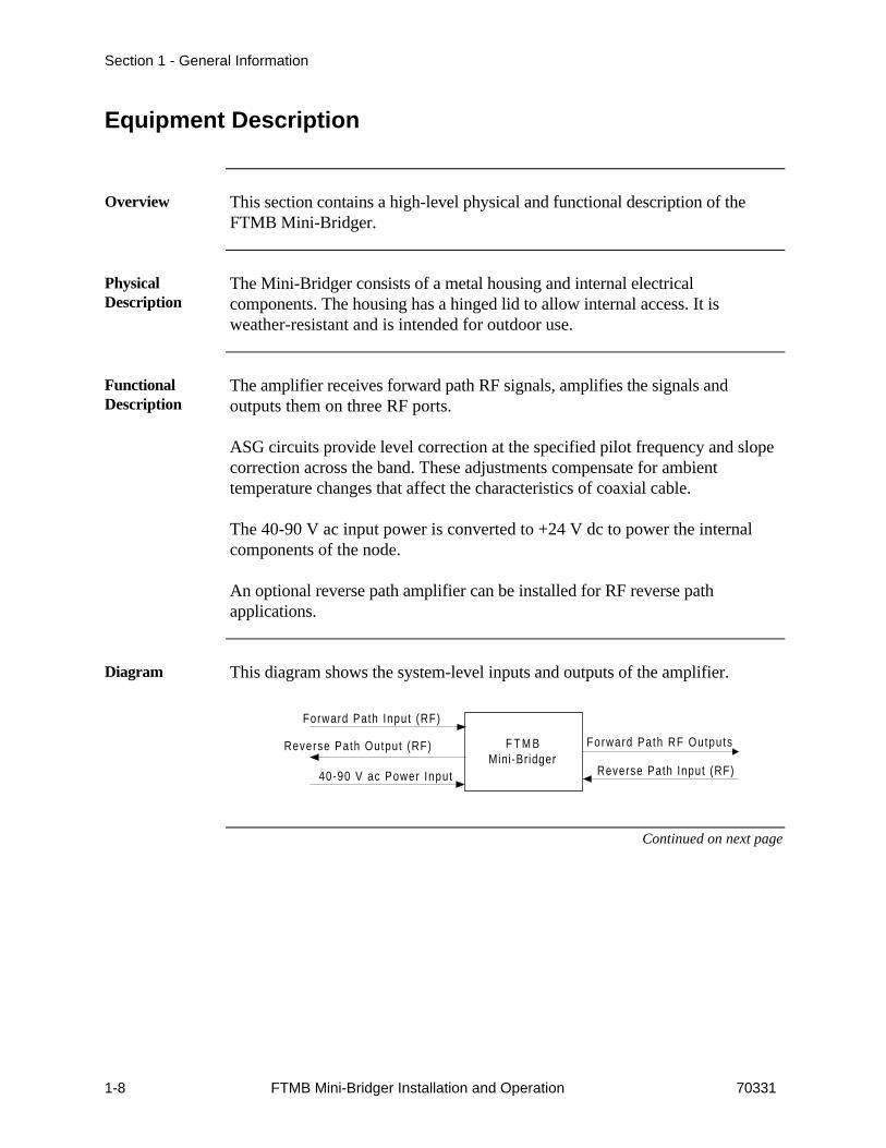
Diagram This diagram shows the system-level inputs and outputs of the amplifier.
F T M BMini-Bridger
Forward Path Input (RF)
Reverse Path Output (RF)
40-90 V ac Power Input
Forward Path RF Outputs
Reverse Path Input (RF)
Continued on next page

Section 1 - General Information
70331 FTMB Mini-Bridger Installation and Operation 1-9
Equipment Description, Continued
Accessories The following accessories are available for the Mini-Bridger:
Accessory FunctionTIK-DA The TIK-DA Vital Link Kit (ANTEC Network
Technologies P/N 473660008) interfaces with the TMC-8055 Opto/RF Amplifier Monitor to provide networkmanagement of FTMB amplifiers. The TIK-DA providesmonitoring of inbound signals, outbound signals andvoltage supply (24 volts and 60 volts) of the hostamplifier through the TMC-8055.
TIK-DAW The TIK-DAW Vital Link Kit (ANTEC NetworkTechnologies P/N 473660007) has the same features asthe TIK-DA described above. In addition, TIK-DAWVital Link Kit also provides control for up to threeR3AB/R6AB “wink switch” reverse path PINattenuators.

Section 1 - General Information
1-10 FTMB Mini-Bridger Installation and Operation 70331
Equipment Specifications
Overview This section describes electrical, physical and environmental specifications ofthe FTMB Mini-Bridger.
ElectricalSpecifications
The tables below list electrical specifications of the FTMB Mini-Bridger.
Mini-Bridger Electrical Specifications
Parameter FTMB-75-36-xx-xx-xx-1S/15Reverse
ASGFixedGain 00- RF- RH-
Passband 45-750 MHz 5-40 MHzOperational Gain 36 dB -10 dB 14 dB 20 dBMinimum Full Gain 42 dB 38.5 dB -9 dB 15 dB 21 dBFrequency Response ±0.75 dB ±0.75 dBSlope/Gain ControlRange 3.5 dB N/AOutput Level Stability 1 dB N/AReturn Loss -14 dB -14 dBTest PointLevel/Accuracy 30±1 dB 30±1 dBNoise Figure 11.7 dB 6 dB 5.2 dBOutput Level(55/550/750 MHz) 38/45/48 dBmV 40 dBmVNonlinear Distortion
Composite SecondOrder 67 dB N/A 87 dB 81 dBComposite TripleBeat 66 dB N/A 79 dB 77 dBCross Modulation 69 dB N/A 75 dB 74 dBHum Modulation 70 dB 60 dB
Chroma DelayCh 2 (55MHz) 27 nsCh 3 (61 MHz) 11 nsAll other channels 7 ns
Continued on next page
Section 1 - General Information
70331 FTMB Mini-Bridger Installation and Operation 1-11
Equipment Specifications, Continued
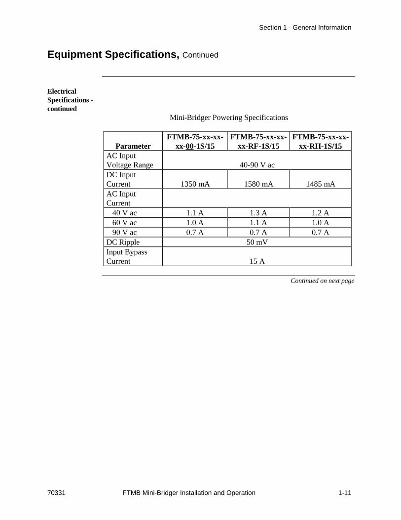
ElectricalSpecifications -continued
Mini-Bridger Powering Specifications
ParameterFTMB-75-xx-xx-
xx-00-1S/15FTMB-75-xx-xx-
xx-RF-1S/15FTMB-75-xx-xx-
xx-RH-1S/15AC InputVoltage Range 40-90 V acDC InputCurrent 1350 mA 1580 mA 1485 mAAC InputCurrent
40 V ac 1.1 A 1.3 A 1.2 A60 V ac 1.0 A 1.1 A 1.0 A90 V ac 0.7 A 0.7 A 0.7 A
DC Ripple 50 mVInput BypassCurrent 15 A
Continued on next page

Section 1 - General Information
1-12 FTMB Mini-Bridger Installation and Operation 70331
Equipment Specifications, Continued
PhysicalSpecifications
The table below lists physical specifications of the FTMB Mini-Bridger.
Item SpecificationLength 12.5 in (31.7 cm)Height 6.75 in (17.1 cm)Width 9.26 in (23.5 cm)Weight 18.6 lb (8.37 kg)
EnvironmentalSpecifications
The table below lists environmental specifications.
Item SpecificationOperating Temperature -40 to +140 ºF (-40 to +60 ºC)Operating Humidity 0 to 95% non-condensing

Section 1 - General Information
70331 FTMB Mini-Bridger Installation and Operation 1-13
List of Abbreviations
Overview This table lists non-standard abbreviations in this manual.
AbbreviationsAbbreviation Definition
AGC automatic gain controlASG automatic slope and gainCDM companded delta modulationC/N carrier-to-noiseCSO composite second orderCTB composite triple beatdB decibeldBc decibel referenced to carrier leveldBm decibel referenced to 1 milliwattdBmV decibel-millivoltDC directional couplerDFB distributed feedbackDSO discrete second orderEQ equalizerFC fuse clipFDM forward detector modulensec nanosecondNTSC National Television Standards Committeepsig pounds per square inch (gauge)RR return for repairRRU reverse receiver unit

Section 1 - General Information
1-14 FTMB Mini-Bridger Installation and Operation 70331
(This Page Intentionally Blank)
**END OF SECTION**

70331 FTMB Mini-Bridger Installation and Operation 2-1
Section 2Installation
Overview
Introduction This section describes installation of the FTMB Mini-Bridger.
In this Section This section contains these major topics.
Topic See PageOverview 2-1Unpacking 2-2Inspection 2-3How to Return Equipment 2-4Recommended Tools and Equipment 2-6Installation 2-7

Section 2 - Installation
2-2 FTMB Mini-Bridger Installation and Operation 70331
Unpacking
Overview ANTEC Network Technologies thoroughly inspects and carefully packs allequipment before shipment. At the time of shipment, the carrier assumesresponsibility for its safe delivery; therefore, do not return damaged units toANTEC Network Technologies.
Procedure Unpack the FTMB Mini-Bridger according to the procedure below.
Step Action1 Inspect the shipping carton for visible damage.2 Open the shipping carton. (Do not destroy shipping cartons until
installation is complete.)3 Remove all packing material.4 Inspect the unit for visible damage.
Section 2 - Installation
70331 FTMB Mini-Bridger Installation and Operation 2-3
Inspection
What to doabout VisibleLoss or Damage
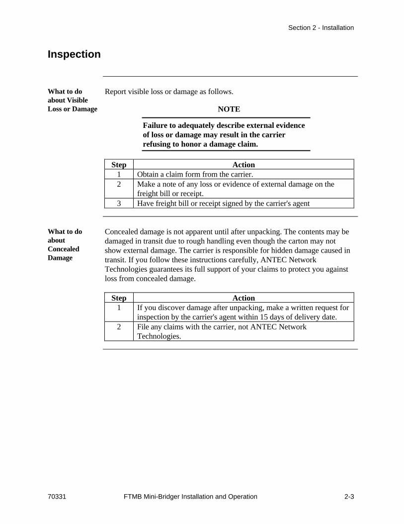
Report visible loss or damage as follows.
NOTE
Failure to adequately describe external evidenceof loss or damage may result in the carrierrefusing to honor a damage claim.
Step Action1 Obtain a claim form from the carrier.2 Make a note of any loss or evidence of external damage on the
freight bill or receipt.3 Have freight bill or receipt signed by the carrier's agent
What to doaboutConcealedDamage
Concealed damage is not apparent until after unpacking. The contents may bedamaged in transit due to rough handling even though the carton may notshow external damage. The carrier is responsible for hidden damage caused intransit. If you follow these instructions carefully, ANTEC NetworkTechnologies guarantees its full support of your claims to protect you againstloss from concealed damage.
Step Action1 If you discover damage after unpacking, make a written request for
inspection by the carrier's agent within 15 days of delivery date.2 File any claims with the carrier, not ANTEC Network
Technologies.

Section 2 - Installation
2-4 FTMB Mini-Bridger Installation and Operation 70331
How to Return Equipment
Overview ANTEC Network Technologies makes every effort to ensure parts andequipment arrive in working condition. Occasionally, it may be necessary toreturn parts or equipment that are not in working condition.
Procedure Follow this procedure to return equipment.
Step Action1 Contact ANTEC Network Technologies . . .
In the US Outside the USCall Technical Service at1-800-FIBERME, press 2 atthe voice prompt and requesta Return for Repair (RR)number.
Contact your sales office forassistance. Sales offices arelisted on the back cover of thismanual.
2 Tag or otherwise identify the defective equipment. Be sure to writethe RR number on the tag. Also, please reference the sales orderand purchase order, and state the date the equipment was received.
3
CAUTION
Do not use Styrofoam chips (peanuts).Use of Styrofoam chips (peanuts) willvoid the warranty.
Pack the equipment in the original container and protective packingmaterial, if possible. If the original packing material is not available,use a sturdy corrugated box and appropriate protective packingmaterial.
Continued on next page
Section 2 - Installation
70331 FTMB Mini-Bridger Installation and Operation 2-5
How to Return Equipment, Continued
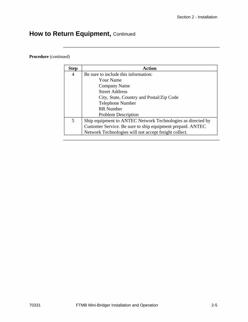
Procedure (continued)
Step Action4 Be sure to include this information:
Your NameCompany NameStreet AddressCity, State, Country and Postal/Zip CodeTelephone NumberRR NumberProblem Description
5 Ship equipment to ANTEC Network Technologies as directed byCustomer Service. Be sure to ship equipment prepaid. ANTECNetwork Technologies will not accept freight collect.

Section 2 - Installation
2-6 FTMB Mini-Bridger Installation and Operation 70331
Recommended Tools and Equipment
Tools andEquipment
These recommended tools and equipment are required for installation.
Quantity Description1 Torque wrench capable of 5 ft/lb (6.8 N·m)1 1/2-inch socket for messenger cable clamp bolts and cover
bolts1 3/8-inch socket for housing bolts1 1/4-inch flat-blade screwdriver

Section 2 - Installation
70331 FTMB Mini-Bridger Installation and Operation 2-7
Installation
Overview The FTMB Mini-Bridger can be mounted on a strand, pedestal or wall. Afterinstallation, refer to the procedures in Section 3, Setup and Operation, toactivate the Mini-Bridger.
In this Section This installation section contains the following procedures.
Topic See PageStrand Mount 2-8Pedestal or Wall Mount 2-9RF Cable Installation 2-10Apply Power 2-11Voltage Check 2-14

Section 2 - Installation
2-8 FTMB Mini-Bridger Installation and Operation 70331
Strand Mount
Description Strand mounting allows street-side access to the housing. After mounting, thecoax and fiber can be connected to either end port of the housing.
Procedure Follow this procedure to mount the housing to the messenger cable.
Step Action1 Loosen the messenger cable clamp bolts.2 Lift the housing and position the strand inside the grooves of the
two messenger cable clamp bolts.3 Use the torque wrench and the 1/2-inch socket to tighten the
messenger cable clamp bolts to 5 ft/lbs (6.8 N·m).4 Continue to RF Cable Installation

Section 2 - Installation
70331 FTMB Mini-Bridger Installation and Operation 2-9
Pedestal or Wall Mount
Description Two threaded holes on the back of the housing allow pedestal or wallmounting.
Procedure Follow this procedure for pedestal or wall mounting.
Step Action1 Secure the housing to the pedestal bracket with the self-tapping
messenger clamp bolts.2 Use the strand clamps for spacers as required.3 Continue to RF Cable Installation

Section 2 - Installation
2-10 FTMB Mini-Bridger Installation and Operation 70331
RF Cable Installation
Overview The RF cables carry both forward and reverse path signals. The RF cables alsosupply the 40-90 V ac power input.
Procedure Install RF cables as follows.
Step Action1 Determine which ports receive an RF cable for your configuration.2 Assemble connector to cable according to manufacturer’s
instructions.3 Trim connector pin length to 30 mm (+1, -2 mm) from connector
shoulder.4 Open the housing according to Opening and Closing the Housing in
Section 3.5 Fully loosen the center conductor seizure screw at the port to
which the cable connects.6 Fit connector to housing and torque to manufacturer’s
specification. Do not exceed recommended torque.7 Verify that the tip of the connector pin is visible through the
inspection hole adjacent to the seizure screw.8 Firmly tighten center conductor seizure screw to ensure contact
with the connector pin. Do not over-tighten.9 Continue to Apply Power.

Section 2 - Installation
70331 FTMB Mini-Bridger Installation and Operation 2-11
Apply Power
Overview The Mini-Bridger requires an input power of 40-90 V ac. This power issupplied by one or more of the RF cables.
WARNING
Hazardous voltages may be present. Do nottouch fuse clips or other exposed terminalsduring these procedures. Failure to observe thiswarning can result in death or severe injury.
Diagram Refer to this diagram to configure Mini-Bridger powering.
I npu tB o a r d
1
2
3
4
5
6 7
8 9 10
F C 1 1
F C 9
F C 1 0
F C 8 F C 7 F C 6 F C 5
F C 1 2 F C 1 3 F C 1 4 F C 1 5
P S
6 0 V 6 0 V9 0 V
O u t p u tB o a r d
Por t 41 5 A m a x
Por t 31 5 A m a x
Por t 11 5 A m a x
Por t 21 5 A m a x
Yel low Wi re
Continued on next page

Section 2 - Installation
2-12 FTMB Mini-Bridger Installation and Operation 70331
Apply Power, Continued
Input Voltage The Mini-Bridger power supply operates in one of two input voltage ranges:• 40-65 V ac• 65-90 V ac
The factory setting is 65-90 V ac. Select input voltage as shown below.
If . . . Then . . .input power is 40-65 V ac remove shunt from position 9 and
install shunts in positions 8 and 10input power is 65-90 V ac verify a shunt is installed in position 9
and no shunts in positions 8 and 10
Port Powering Refer to the powering diagram. Install shunts in the positions necessary foryour powering requirements. There are many possible configurations. Refer toyour network design diagrams and use the examples below as a guideline.
PoweringExample 1
Power the Mini-Bridger through port 1 and have power output on all ports.
Step Action1 Install shunts in positions 1, 2, 3, 4 and 5.2 Verify yellow wire is installed in fuse clip FC11.
PoweringExample 2
Power the Mini-Bridger through port 1 and power ports 2, 3 and 4 throughthe ac powering port.
Step Action1 Install shunt in position 6 to power the Mini-Bridger.2 Install a jumper wire between FC5 and FC9.3 Install shunts in positions 2, 3, and 4.4 Verify yellow wire is installed in fuse clip FC11.
Continued on next page

Section 2 - Installation
70331 FTMB Mini-Bridger Installation and Operation 2-13
Apply Power, Continued
PoweringExample 3
Power the Mini-Bridger through port 1 and power out through port 3 only.Separately power ports 2 and 4 through ac powering port.
Step Action1 Install shunt in position 6.2 Move yellow wire to FC6.3 Install a jumper wire between FC5 and FC9.4 Install shunts in positions 2 and 4.
PoweringExample 4
Power the Mini-Bridger through the ac powering port and power out throughports 2, 3 and 4. No power at port 1..
Step Action1 Install shunts in positions 2, 3, 4, 5 and 7.2 Verify yellow wire is installed in fuse clip FC11.

Section 2 - Installation
2-14 FTMB Mini-Bridger Installation and Operation 70331
Voltage Check
Overview Always check both ac and dc voltages during initial setup of the amplifier.
Procedure Check ac and dc voltages as follows.
Step Action1 Check for 40-90 V ac input voltage at white ac test point on the
power distribution board.2 Check for +24 V dc output voltage of the power supply at red dc
test point on the power distribution board.3 If necessary, continue to the alignment procedures in Section 3;
otherwise, close the housing according to Opening and Closing theHousing in Section 3.
**END OF SECTION**

70331 FTMB Mini-Bridger Installation and Operation 3-1
Section 3Setup and Operation
Overview
Introduction This section describes how to set up and operate the FTMB Mini-Bridger.These procedures assume the amplifier is installed according to the proceduresin Section 2 of this manual.
In this SectionTopic See Page
Overview 3-1Tools and Test Equipment 3-2Forward Path Setup 3-3Reverse Path Setup 3-5Mini-Bridger Plug-Ins 3-6Maintenance 3-10

Section 3 - Setup and Operation
3-2 FTMB Mini-Bridger Installation and Operation 70331
Tools and Test Equipment
Overview Tools and test equipment required for setup are listed below
Tools andEquipment
Equivalent items may be substituted. Ensure test equipment is calibrated and ingood working order.
Manufacturer andModel Number
Description
Fluke 77 Digital voltmeter with .001 V dc resolution- Signal level meter- Pads and equalizers as necessary. Refer to
Mini-Bridger Plug-Ins in this section.- Torque wrench capable of 5 ft/lbs (6.8 N·m)- 1/2-in socket for messenger cable clamp bolts and
cover bolts- 3/8-in socket for housing bolts
Section 3 - Setup and Operation
70331 FTMB Mini-Bridger Installation and Operation 3-3
Forward Path Setup
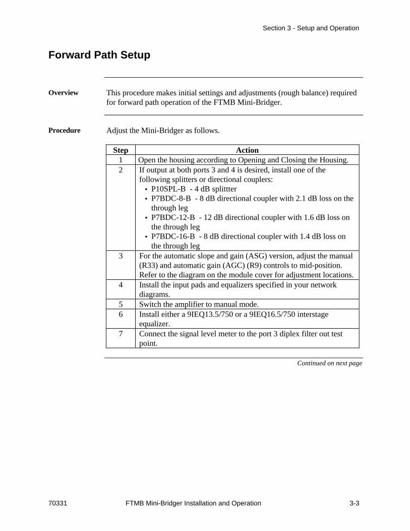
Overview This procedure makes initial settings and adjustments (rough balance) requiredfor forward path operation of the FTMB Mini-Bridger.
Procedure Adjust the Mini-Bridger as follows.
Step Action1 Open the housing according to Opening and Closing the Housing.2 If output at both ports 3 and 4 is desired, install one of the
following splitters or directional couplers:• P10SPL-B - 4 dB splittter• P7BDC-8-B - 8 dB directional coupler with 2.1 dB loss on the
through leg• P7BDC-12-B - 12 dB directional coupler with 1.6 dB loss on
the through leg• P7BDC-16-B - 8 dB directional coupler with 1.4 dB loss on
the through leg3 For the automatic slope and gain (ASG) version, adjust the manual
(R33) and automatic gain (AGC) (R9) controls to mid-position.Refer to the diagram on the module cover for adjustment locations.
4 Install the input pads and equalizers specified in your networkdiagrams.
5 Switch the amplifier to manual mode.6 Install either a 9IEQ13.5/750 or a 9IEQ16.5/750 interstage
equalizer.7 Connect the signal level meter to the port 3 diplex filter out test
point.
Continued on next page

Section 3 - Setup and Operation
3-4 FTMB Mini-Bridger Installation and Operation 70331
Forward Path Setup, Continued
Procedure (continued)
Step Action8 Adjust the input pad and equalizer to achieve the correct slope and
level. Note that the output level at port 3 is 8 dB lower than theoutput level at ports 2 and 4.
9 Perform the following steps only for the ASG version of theMini-Bridger:
Step Action1 Switch the amplifier to AUTO mode.2
NOTE
For the ASG version, a pilot carrier at thecorrect frequency must be present. Thefrequency of the pilot carrier is stampedon top of the ASG unit. If a pilot carrier isnot present, the output levels will oscillateas the detector tries to track the noise.
Allow 30 seconds for the output to stabilize.3 Adjust R9 to achieve the correct output level.

Section 3 - Setup and Operation
70331 FTMB Mini-Bridger Installation and Operation 3-5
Reverse Path Setup
Overview This procedure aligns the reverse path of the Mini-Bridger. It balances thereverse path for constant inputs. This balancing compensates for the lossbetween the amplifier being balanced and the next reverse amplifier in thecascade.
This procedure requires two technicians. The technicians must be able tocommunicate to each other from remote locations.
Signal Levels Typically, return signals should arrive at the amplifier with a minimum level of20 dBmV. The output level of the return signal from the amplifier isapproximately 35 dBmV, but the slope and gain must be adjusted so that thelevel into the next system unit is correct for that unit.
Procedure Align the reverse path as follows.
Step Action1 Adjust the signal generator to give a signal of +50 dBmV at both
high and low reverse carrier frequencies.2
NOTE
Ensure all factory jumpers are installed inthe return pad and equalizer locations.
Connect the signal generator to the reverse test point of theamplifier being balanced.
3 At the next amplifier “upstream,” connect the signal level meter tothe “in” test point of the port that feeds the amplifier being aligned.
4 At the amplifier being aligned, install an equalizer that results in aflat signal at the “upstream” amplifier.
5 At the amplifier being aligned, install a pad that results in thecorrect signal level at the upstream amplifier.
6 Move the signal source to the next amplifier (the previous receiveamplifier) and repeat steps 1-5.

Section 3 - Setup and Operation
3-6 FTMB Mini-Bridger Installation and Operation 70331
Mini-Bridger Plug-Ins
Overview Forward and reverse path setups require pads and equalizers of various values.The tables below show reverse equalizer plug-in losses and cable equivalents.
Tables Refer to the tables below as necessary.
Reverse Equalizer Plug-In Losses
REQ 9REQ-3X 9REQ-4X 9REQ-5X5 MHz 30 MHz 5 MHz 40 MHz 5 MHz 55 MHz
A 1.7 0.8 2.1 0.8 2.2 0.8B 2.6 0.8 3.4 0.8 3.6 0.8C 3.5 0.8 4.7 0.8 5 0.8D 4.4 0.8 6 0.8 6.4 0.8
Cable Equivalents
Part No. 50 MHz 550 MHz 650 MHz 750 MHz9PCE-1.5 0.5 1.4 1.5 1.69PCE-3.0 0.5 2.8 3.0 3.29PCE-4.5 0.5 4.1 4.5 4.99PCE-6.0 0.5 5.5 6.0 6.59PCE-7.5 0.5 6.9 7.5 8.19PCE-9.0 0.5 8.3 9.0 9.89PCE-10.5 0.5 9.6 10.5 11.4
Continued on next page

Section 3 - Setup and Operation
70331 FTMB Mini-Bridger Installation and Operation 3-7
Mini-Bridger Plug-Ins, Continued
Tables -continued
Refer to the tables below as necessary.
Attenuators
Model Value9PD1-0 0 dB9PD1-1 1 dB9PD1-2 2 dB9PD1-3 3 dB9PD1-4 4 dB9PD1-5 5 dB9PD1-6 6 dB9PD1-7 7 dB9PD1-8 8 dB9PD1-9 9 dB9PD1-10 10 dB9PD1-11 11 dB9PD1-12 12 dB9PD1-13 13 dB9PD1-14 14 dB9PD1-15 15 dB9PD1-16 16 dB9PD1-17 17 dB9PD1-18 18 dB9PD1-19 19 dB9PD1-20 20 dB
Continued on next page
Section 3 - Setup and Operation
3-8 FTMB Mini-Bridger Installation and Operation 70331
Mini-Bridger Plug-Ins, Continued
Tables -continued
Refer to the tables below as necessary.
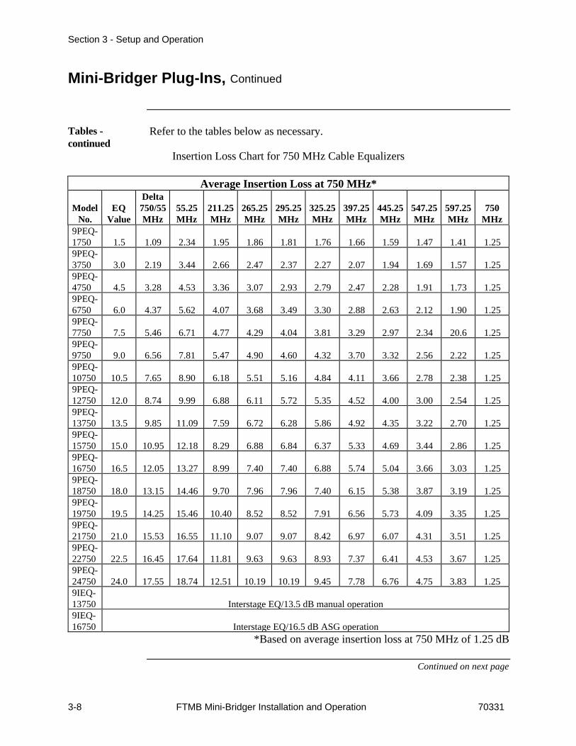
Insertion Loss Chart for 750 MHz Cable Equalizers
Average Insertion Loss at 750 MHz*
ModelNo.
EQValue
Delta750/55MHz
55.25MHz
211.25MHz
265.25MHz
295.25MHz
325.25MHz
397.25MHz
445.25MHz
547.25MHz
597.25MHz
750MHz
9PEQ-1750 1.5 1.09 2.34 1.95 1.86 1.81 1.76 1.66 1.59 1.47 1.41 1.259PEQ-3750 3.0 2.19 3.44 2.66 2.47 2.37 2.27 2.07 1.94 1.69 1.57 1.259PEQ-4750 4.5 3.28 4.53 3.36 3.07 2.93 2.79 2.47 2.28 1.91 1.73 1.259PEQ-6750 6.0 4.37 5.62 4.07 3.68 3.49 3.30 2.88 2.63 2.12 1.90 1.259PEQ-7750 7.5 5.46 6.71 4.77 4.29 4.04 3.81 3.29 2.97 2.34 20.6 1.259PEQ-9750 9.0 6.56 7.81 5.47 4.90 4.60 4.32 3.70 3.32 2.56 2.22 1.259PEQ-10750 10.5 7.65 8.90 6.18 5.51 5.16 4.84 4.11 3.66 2.78 2.38 1.259PEQ-12750 12.0 8.74 9.99 6.88 6.11 5.72 5.35 4.52 4.00 3.00 2.54 1.259PEQ-13750 13.5 9.85 11.09 7.59 6.72 6.28 5.86 4.92 4.35 3.22 2.70 1.259PEQ-15750 15.0 10.95 12.18 8.29 6.88 6.84 6.37 5.33 4.69 3.44 2.86 1.259PEQ-16750 16.5 12.05 13.27 8.99 7.40 7.40 6.88 5.74 5.04 3.66 3.03 1.259PEQ-18750 18.0 13.15 14.46 9.70 7.96 7.96 7.40 6.15 5.38 3.87 3.19 1.259PEQ-19750 19.5 14.25 15.46 10.40 8.52 8.52 7.91 6.56 5.73 4.09 3.35 1.259PEQ-21750 21.0 15.53 16.55 11.10 9.07 9.07 8.42 6.97 6.07 4.31 3.51 1.259PEQ-22750 22.5 16.45 17.64 11.81 9.63 9.63 8.93 7.37 6.41 4.53 3.67 1.259PEQ-24750 24.0 17.55 18.74 12.51 10.19 10.19 9.45 7.78 6.76 4.75 3.83 1.259IEQ-13750 Interstage EQ/13.5 dB manual operation9IEQ-16750 Interstage EQ/16.5 dB ASG operation
*Based on average insertion loss at 750 MHz of 1.25 dB
Continued on next page
Section 3 - Setup and Operation
70331 FTMB Mini-Bridger Installation and Operation 3-9
Mini-Bridger Plug-Ins, Continued
Tables -continued
Refer to the tables below as necessary.
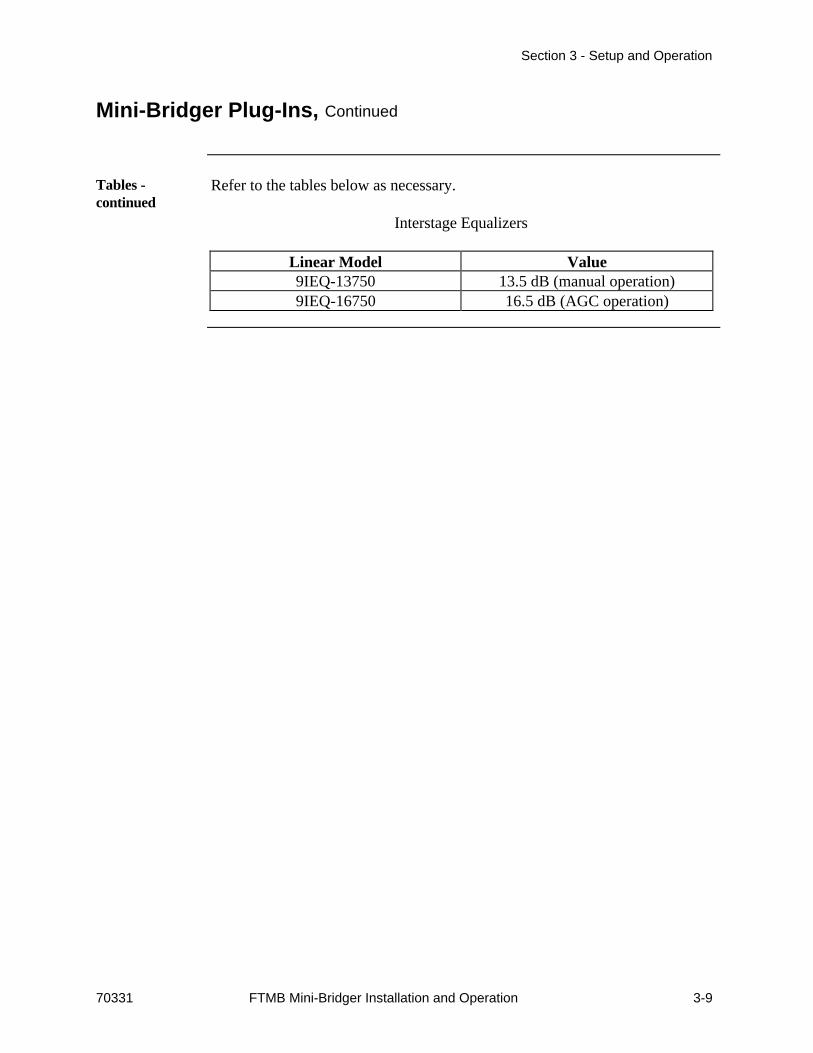
Interstage Equalizers
Linear Model Value9IEQ-13750 13.5 dB (manual operation)9IEQ-16750 16.5 dB (AGC operation)

Section 3 - Setup and Operation
3-10 FTMB Mini-Bridger Installation and Operation 70331
Maintenance
Overview This section describes maintenance procedures for the Mini-Bridger.
In this Section This maintenance section contains the following topics.
Topic See PagePreventive Maintenance 3-11Opening and Closing the Housing 3-16

Section 3 - Setup and Operation
70331 FTMB Mini-Bridger Installation and Operation 3-11
Preventive Maintenance
Overview Preventive maintenance procedures are regularly scheduled actions that helpprevent failures and maintain the appearance of the equipment.
Schedule Perform the preventive maintenance procedures at these intervals.
Procedure Interval SeePage
Visual Inspection 3-12External Surfaces SemiannuallyConnectors SemiannuallyIndicators SemiannuallyWiring/Cable Assemblies Annually
Cleaning 3-13External Surfaces AnnuallyExternal Controls/Connectors AnnuallyInternal Connectors/Circuit Cards Annually
Continued on next page

Section 3 - Setup and Operation
3-12 FTMB Mini-Bridger Installation and Operation 70331
Preventive Maintenance, Continued
VisualInspection
Visually inspect the following items.
What to Inspect How to InspectExterior surfaces Inspect for:
• dust, dirt, lubricants or other foreign matter• worn spots or deep scratches on surfaces• corrosion• marred protective finish exposing bare metal• missing, incorrect or obliterated marking,
decals or reference designators.Connectors Inspect for:
• broken, loose, bent, corroded or missing pins• cracked insulator inserts
Indicators Inspect for• cracked or missing lenses
Wiring and cables Inspect for:• cuts, nicks, burns or abrasions• exposed bare conductors• sharp bends• pinched or damaged wires• broken or loose lacing, tie wraps or clamps
Continued on next page

Section 3 - Setup and Operation
70331 FTMB Mini-Bridger Installation and Operation 3-13
Preventive Maintenance, Continued
Cleaning Clean exterior surfaces of the equipment at least annually.
ConsumableMaterials
Use the materials listed below (or equivalent) when cleaning the equipment.
Item SpecificationIsopropyl alcohol TT-I-735Cheesecloth CC-C-440Spray-type contact cleaner None
Procedure Clean the equipment as described below.
Step Action1 Use a small paint brush to brush dust from connectors.2 Wipe surfaces dry with clean, dry cheesecloth.
Continued on next page
Section 3 - Setup and Operation
3-14 FTMB Mini-Bridger Installation and Operation 70331
Preventive Maintenance, Continued
Procedure (continued)
Step Action3
WARNING
Isopropyl alcohol is flammable. Useisopropyl alcohol only in well-ventilatedareas away from energized electricalcircuits and heated objects such assoldering irons or open flames. Avoidexcessive inhalation of vapors orprolonged or repeated contact with skin.Wear industrial rubber gloves andindustrial safety goggles to avoid contactwith skin. Do not take internally. Failureto comply with this warning can causeinjury, physical disorder or death.
CAUTION
Do not use cleaning fluids containingtricholorethylene, tricholorethane,acetone or petroleum-based cleaners onequipment. Failure to comply with thiscaution could harm equipment surfaces.
Clean exterior surfaces with clean cheesecloth moistened withisopropyl alcohol or general-purpose detergent. Do not let alcoholor detergent get inside equipment or connectors.
4 Clean electrical contacts with spray-type contact cleaner.5 Clean internal connectors and circuit boards with hand-controlled,
dry-air jet. Do not use pressure exceeding 15 lb/in2 psig(1.05 kg/cm2, or 103.43 kPa).
6 Clean fans with a brush and dry-air jet.
Continued on next page

Section 3 - Setup and Operation
70331 FTMB Mini-Bridger Installation and Operation 3-15
Preventive Maintenance, Continued
Procedure(continued)
Step Action7 Clean interior surfaces with clean cheesecloth moistened with
isopropyl alcohol or general-purpose detergent.8 Clean internal electrical contacts with clean cheesecloth moistened
with spray-type contact cleaner.9 Dry interior with clean, dry cheesecloth.

Section 3 - Setup and Operation
3-16 FTMB Mini-Bridger Installation and Operation 70331
Opening and Closing the Housing
Overview Installation or maintenance of the amplifier requires opening the housing toaccess the internal modules.
Proper housing closure is important to maintaining the amplifier in goodworking condition. Proper closure ensures a good seal against theenvironment, protecting the internal modules.
Opening theHousing
Open the housing as follows.
Step Action1 Remove the bolts securing the lid to the housing.2 Carefully open the lid to allow access to the inside of the housing.3 Inspect gaskets on the cover flange and on the test port plugs.4 Replace any gaskets showing signs of wear (cracked, twisted,
pinched or dry) with new, lubricated gaskets.
Closing theHousing
Close the housing as follows.
Step Action1 Ensure gaskets are clean and undamaged.2
CAUTION
Use caution when closing housing.Improper closing may result in the nodenot being sealed from the elements.
Carefully close the lid. Be sure the alignment pins on the base lineup with the holes in the lid.
3 For strand-mounted housings, pull the lid away from the base andremove the slack from the hinge before while rotating the lid uptoward the base.
Continued on next page
Section 3 - Setup and Operation
70331 FTMB Mini-Bridger Installation and Operation 3-17
Opening and Closing the Housing, Continued
Closing the Housing (continued)
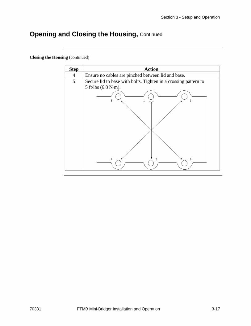
Step Action4 Ensure no cables are pinched between lid and base.5 Secure lid to base with bolts. Tighten in a crossing pattern to
5 ft/lbs (6.8 N·m).
315
624

Section 3 - Setup and Operation
3-18 FTMB Mini-Bridger Installation and Operation 70331
(This Page Intentionally Blank)
**END OF SECTION**

70331 Mini-Bridger Installation and Operation 4-1
Section 4Theory of Operation
Overview
Introduction This section describes the theory of operation of the FTMB Mini-Bridger.
In this Section This section contains these major topics.
Topic See PageOverview 4-1Basic Theory 4-2Detailed Theory 4-5
Section 4 - Theory of Operation
4-2 Mini-Bridger Installation and Operation 70331
Basic Theory
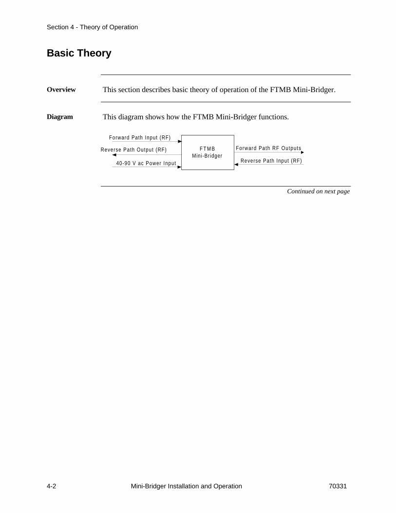
Overview This section describes basic theory of operation of the FTMB Mini-Bridger.
Diagram This diagram shows how the FTMB Mini-Bridger functions.
F T M BMini-Bridger
Forward Path Input (RF)
Reverse Path Output (RF)
40-90 V ac Power Input
Forward Path RF Outputs
Reverse Path Input (RF)
Continued on next page
Section 4 - Theory of Operation
70331 Mini-Bridger Installation and Operation 4-3
Basic Theory, Continued
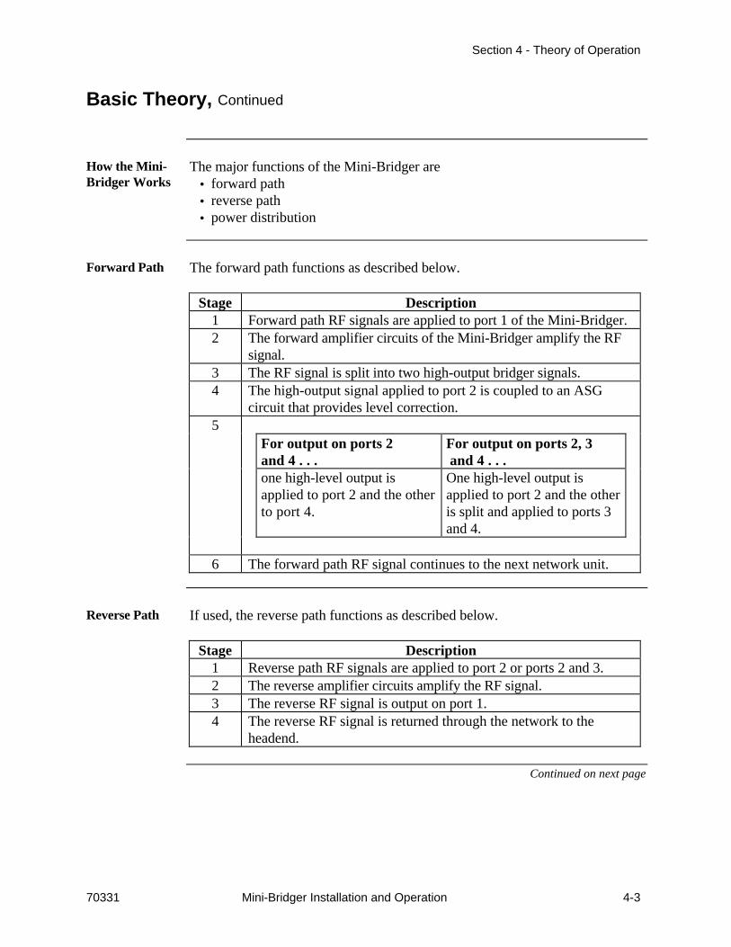
How the Mini-Bridger Works
The major functions of the Mini-Bridger are• forward path• reverse path• power distribution
Forward Path The forward path functions as described below.
Stage Description1 Forward path RF signals are applied to port 1 of the Mini-Bridger.2 The forward amplifier circuits of the Mini-Bridger amplify the RF
signal.3 The RF signal is split into two high-output bridger signals.4 The high-output signal applied to port 2 is coupled to an ASG
circuit that provides level correction.5
For output on ports 2and 4 . . .
For output on ports 2, 3 and 4 . . .
one high-level output isapplied to port 2 and the otherto port 4.
One high-level output isapplied to port 2 and the otheris split and applied to ports 3and 4.
6 The forward path RF signal continues to the next network unit.
Reverse Path If used, the reverse path functions as described below.
Stage Description1 Reverse path RF signals are applied to port 2 or ports 2 and 3.2 The reverse amplifier circuits amplify the RF signal.3 The reverse RF signal is output on port 1.4 The reverse RF signal is returned through the network to the
headend.
Continued on next page

Section 4 - Theory of Operation
4-4 Mini-Bridger Installation and Operation 70331
Basic Theory, Continued
PowerDistribution
Power distribution functions as described below.
Stage Description1 40-90 V ac is applied to the power supply in the Mini-Bridger.2 The power supply converts the ac input to +24 V dc.3 The +24 V dc is routed to internal modules.

Section 4 - Theory of Operation
70331 Mini-Bridger Installation and Operation 4-5
Detailed Theory
Overview This section describes detailed theory of operation of the FTMB Mini-Bridger.
In this Section The detailed theory discussion is divided into these areas.
Topic See PageForward Path 4-7Reverse Path 4-9Power Distribution 4-10
Continued on next page

Section 4 - Theory of Operation
4-6 Mini-Bridger Installation and Operation 70331
Detailed Theory, Continued
Diagram Refer to the detailed theory diagram below as necessary.
-30DCTP
1
2
3
AC
IN
4
HIGH
LOW
EQ PAD
PAD
ASGCIRCUIT
HIGH
LOW
OptionalPeaker
ASG Coupler
EQ
LPFilter
(Built-In)Splitter
P7DF-XX
LOW
HIGH
LOW
HIGH
PAD EQ
PAD
PADPAD
P7DF-XX
P7DF-XXP7DF-XX
HY1 HY3
HY2 HY4
HY5
*OptionalSplitter orCoupler
-30 dBInputTP
-30 dBOutput
TP
-30 dBInputTP
-30 dBOutput
TP
-30 dBInputTP
-30 dBOutput
TP
-30 dBInputTP
-30 dBOutput
TP
PAD
*P10SPL-B SplitterP7DC-XX-B Directional Coupler (thru on Port
P7DC-XX-BW Directional Coupler (thru on Port
PAD

Section 4 - Theory of Operation
70331 Mini-Bridger Installation and Operation 4-7
Forward Path
Overview Forward path refers to signals sent from the headend or hub to the FTMBMini-Bridger. These signals are usually 54-750 MHz RF signals.
How theForward PathWorks
The forward path operates as described below.
Stage Description1 Forward path RF signals are applied to port 1 of the Mini-Bridger
from network RF cables.2 A -30 dB resistive test point allows monitoring of the input RF
signal.3 The RF signal is then applied to the high side of an input diplex
filter.4 The output of the filter is applied to a plug-in pad/equalizer
network. The values of these components may vary according tonetwork needs.
5 The output of the equalizer is applied to hybrid HY1.6 HY1 amplifies the signal and applies it to an interstage pad and
equalizer circuit.7
In the ASG Mini-Bridger .. .In the non-ASG Mini-Bridger . . .
• The RF signal is thenapplied to an automaticslope-compensated gaincircuit.
• The ASG circuit uses thehigh-level output of HY2 asa reference signal to vary thegain.
• The output of the ASGcircuit passes through anoptional peaker and isapplied to HY3.
• There is no ASG circuit.• The signal is applied
through the optional peakerdirectly to HY3.
Continued on next page

Section 4 - Theory of Operation
4-8 Mini-Bridger Installation and Operation 70331
Forward Path, Continued
How the Forward Path Works (continued)
Step Action8 HY3 produces an amplified signal that is split into two
components.9 One component is applied through a pad to bridger amplifier HY2.10 The other component is applied through a pad to bridger amplifier
HY4.12 The output of HY2 is split into two components.13 The through leg is applied through the high side of a diplex filter
and a -30 dB test point to output port 2.14 The tap leg provides the reference signal to the ASG circuit.15
If port 3 is active . . . If port 3 is not active . . .• The output of HY4 is split
into two components by anoptional splitter or coupler
• One component is appliedthrough the high side of adiplex filter and a -30 dBtest point to output port 3
• The other component isapplied through the highside of a diplex filter and a-30 dB test point to outputport 4.
• The output of HY4 isapplied through the highside of a diplex filter and a-30 dB test point to outputport 4.
Continued on next page

Section 4 - Theory of Operation
70331 Mini-Bridger Installation and Operation 4-9
Reverse Path
Over view Reverse path refers to signals sent from the FTMB Mini-Bridger to theheadend or hub. These are lower frequency signals than the forward pathsignals, and are usually in the range of 5-40 MHz.
To activate the reverse path, hybrid HY5 and associated pads and equalizermust be installed.
How theReverse PathWorks
The reverse path operates as described below.
Stage Description1 Reverse path RF signals are applied to ports 3 and/or 4.2 The RF signals are applied to the low side of the output diplex
filters at ports 3 and/or 4.3 The output of the filter is applied to a pad. Value of the pad is
determined by network requirements.4 The two signals are combined and applied to hybrid HY5.5 The reverse signal is also coupled directly to port 2 without
amplification.6 HY5 amplifies the reverse path signal.7 The output of HY5 is applied through a low-pass filter to a
pad/equalizer circuit.8 The signal is then applied to the low side of the diplex filter at
port 1.9 The output of the filter can be monitored at a -30 dB test point.10 The reverse path RF signal is output on port 1.11 The reverse path RF is routed over the network to the headend or
hub.

Section 4 - Theory of Operation
4-10 Mini-Bridger Installation and Operation 70331
Power Distribution
Overview The FTMB Mini-Bridger requires an input power of 40-90 V ac. Powerdistribution is described below.
PowerDistribution
Power is input to the FTMB Mini-Bridger as described below.
Stage Description1 40-90 V ac power is input to the Mini-Bridger through at least one
of the RF ports.2 Shunts route the ac power to the power supply input bus.3 The power supply input bus routes ac power to the power supply
ac input.4 The power supply produce a +24 V dc output.5 The +24 V dc output is routed to the internal modules of the
amplifier.
**END OF SECTION**

(This Page Intentionally Left Bank)

United States Asia Pacific Latin AmericaGlobal Headquarters Beijing Miami11450 TechnologyCircle Unit 876 8578 NW 23rd StreetDuluth, GA 30097 USA Poly Plaza Miami, FL 33122 USAP. 678-473-2000 no. 14 Dongzhimen Nandajie P. 305-592-3948F.678-473-8182 Dongcheng District F. 305-592-9646
Beijing 100027, People’s Republic of ChinaCanada P. 86-10-6501-1876 ArgentinaToronto F. 86-10-6501-1296 Av. Juan de Garay 840 3 Piso1458 Epping Road Buenos Aires, Argentina 1153Burlington, Ontario L7M IP4 Shanghai P. 541-300-2333P. 905-332-5166 2004 Nanjing West Road F. 541-300-0083F. 905-332-9630 Shanghai International Business Centre
Suite 412 BrazilEurope Shanghai 200040 Rua Luiz Carlos Prestes, 350Milan People’s Republic of China Suite 205-206C&S S.R.L. P. 86-21-6248-4589 Barra Trade II, Barra da TijucaStrada Malaspina, 12 F. 86-21-6248-1018 Rio de Janeiro, RJ Brasil 2279320090 S. Felice-Segrate P. 5521-430-8829Milan, Italy Hong Kong F. 5521-430-8930P. +39-2-70301049 Unit 1814, Miramar TowerF. +39-2-70301049 1-23 Kimberley Road Venezuela
TST, Kowloon, Hong Kong Ave. Rio de JaneiroUnited Kingdom P. 852-2735-3131 Edf. ELE - Piso 1 Ofic. No. 2Watermeadow House F. 852-2736-7171 Las MercedesWatermeadow Caracas, VenezuelaChesham, Bucks HP5 1LF Singapore P. 582-993-2340United Kingdom Block 105, #09-2182 F. 582-993-1468P. +44-1494-776060 Bedok North Avenue 4F. +44-1494-773397 Singapore 460105 Mexico
P. 65-245-1175 Leona Vicario 710-A desp. 001Internet F. 65-245-1165 Col. La Purisimawww.antec.com Metepec, Edo. de Mexico
C.P. 52140, MexicoP. 52-72-12-45-93F. 52-72-12-45-94
70331