Embed Size (px)
Citation preview

740/760 Control255 and Performa Series
Valves (268, 268FA)Operation Manual
For Sales & Service questions please contact your dealer:
Your local dealer is:
2 TABLE OF CONTENTSRev E
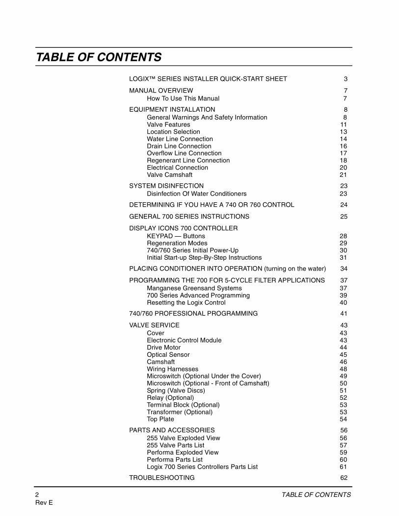
TABLE OF CONTENTS
LOGIX™ SERIES INSTALLER QUICK-START SHEET 3
MANUAL OVERVIEW 7How To Use This Manual 7
EQUIPMENT INSTALLATION 8General Warnings And Safety Information 8Valve Features 11Location Selection 13Water Line Connection 14Drain Line Connection 16Overflow Line Connection 17Regenerant Line Connection 18Electrical Connection 20Valve Camshaft 21
SYSTEM DISINFECTION 23Disinfection Of Water Conditioners 23
DETERMINING IF YOU HAVE A 740 OR 760 CONTROL 24
GENERAL 700 SERIES INSTRUCTIONS 25
DISPLAY ICONS 700 CONTROLLERKEYPAD — Buttons 28Regeneration Modes 29740/760 Series Initial Power-Up 30Initial Start-up Step-By-Step Instructions 31
PLACING CONDITIONER INTO OPERATION (turning on the water) 34
PROGRAMMING THE 700 FOR 5-CYCLE FILTER APPLICATIONS 37Manganese Greensand Systems 37700 Series Advanced Programming 39Resetting the Logix Control 40
740/760 PROFESSIONAL PROGRAMMING 41
VALVE SERVICE 43Cover 43Electronic Control Module 43Drive Motor 44Optical Sensor 45Camshaft 46Wiring Harnesses 48Microswitch (Optional Under the Cover) 49Microswitch (Optional - Front of Camshaft) 50Spring (Valve Discs) 51Relay (Optional) 52Terminal Block (Optional) 53Transformer (Optional) 53Top Plate 54
PARTS AND ACCESSORIES 56255 Valve Exploded View 56255 Valve Parts List 57Performa Exploded View 59Performa Parts List 60Logix 700 Series Controllers Parts List 61
TROUBLESHOOTING 62
LOGIX™ SERIES INSTALLER QUICK-START SHEET 3Rev E
QU
ICK
STA
RT
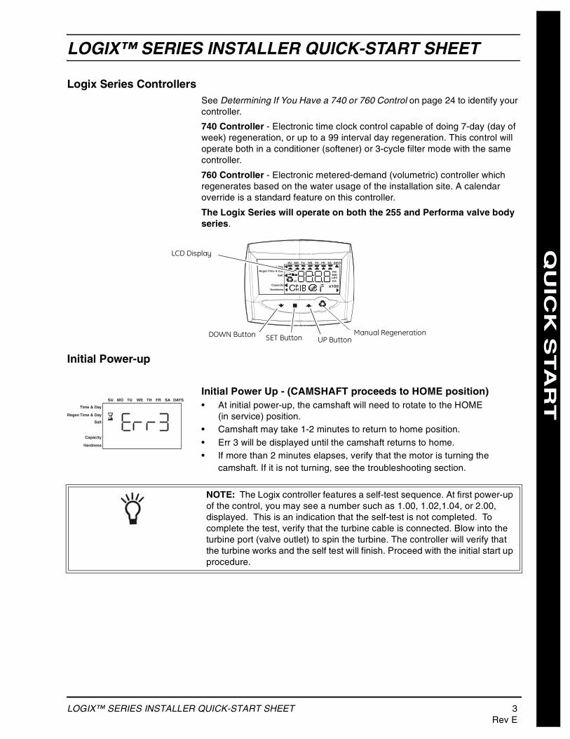
LOGIX™ SERIES INSTALLER QUICK-START SHEET
Logix Series ControllersSee Determining If You Have a 740 or 760 Control on page 24 to identify your controller.
740 Controller - Electronic time clock control capable of doing 7-day (day of week) regeneration, or up to a 99 interval day regeneration. This control will operate both in a conditioner (softener) or 3-cycle filter mode with the same controller.
760 Controller - Electronic metered-demand (volumetric) controller which regenerates based on the water usage of the installation site. A calendar override is a standard feature on this controller.
The Logix Series will operate on both the 255 and Performa valve body series.
Initial Power-up
Initial Power Up - (CAMSHAFT proceeds to HOME position)• At initial power-up, the camshaft will need to rotate to the HOME
(in service) position.• Camshaft may take 1-2 minutes to return to home position.• Err 3 will be displayed until the camshaft returns to home.• If more than 2 minutes elapses, verify that the motor is turning the
camshaft. If it is not turning, see the troubleshooting section.
Time & Day
Regen Time & Day
Salt
SU MO TU WE TH FR SA DAYS
LBS
PMMIN
KG
x100x2
PHC
Capacity
Hardness
Manual RegenerationUP ButtonSET ButtonDOWN Button
LCD Display
Time & Day
Regen Time & Day
Salt
Capacity
Hardness
SU MO TU WE TH FR SA DAYS
NOTE: The Logix controller features a self-test sequence. At first power-up of the control, you may see a number such as 1.00, 1.02,1.04, or 2.00, displayed. This is an indication that the self-test is not completed. To complete the test, verify that the turbine cable is connected. Blow into the turbine port (valve outlet) to spin the turbine. The controller will verify that the turbine works and the self test will finish. Proceed with the initial start up procedure.
4 LOGIX™ SERIES INSTALLER QUICK-START SHEETRev E
QU
ICK
STA
RT
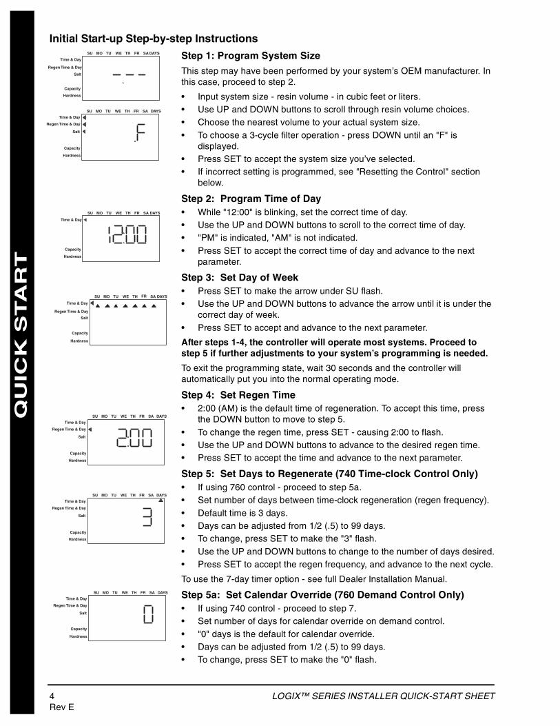
Initial Start-up Step-by-step Instructions
Step 1: Program System Size
This step may have been performed by your system’s OEM manufacturer. In this case, proceed to step 2.
• Input system size - resin volume - in cubic feet or liters.• Use UP and DOWN buttons to scroll through resin volume choices.• Choose the nearest volume to your actual system size.• To choose a 3-cycle filter operation - press DOWN until an "F" is
displayed.• Press SET to accept the system size you’ve selected.• If incorrect setting is programmed, see "Resetting the Control" section
below.
Step 2: Program Time of Day• While "12:00" is blinking, set the correct time of day.• Use the UP and DOWN buttons to scroll to the correct time of day.• "PM" is indicated, "AM" is not indicated.• Press SET to accept the correct time of day and advance to the next
parameter.
Step 3: Set Day of Week• Press SET to make the arrow under SU flash.• Use the UP and DOWN buttons to advance the arrow until it is under the
correct day of week.• Press SET to accept and advance to the next parameter.
After steps 1-4, the controller will operate most systems. Proceed to step 5 if further adjustments to your system’s programming is needed.
To exit the programming state, wait 30 seconds and the controller will automatically put you into the normal operating mode.
Step 4: Set Regen Time• 2:00 (AM) is the default time of regeneration. To accept this time, press
the DOWN button to move to step 5.• To change the regen time, press SET - causing 2:00 to flash.• Use the UP and DOWN buttons to advance to the desired regen time.• Press SET to accept the time and advance to the next parameter.
Step 5: Set Days to Regenerate (740 Time-clock Control Only)• If using 760 control - proceed to step 5a.• Set number of days between time-clock regeneration (regen frequency).• Default time is 3 days.• Days can be adjusted from 1/2 (.5) to 99 days.• To change, press SET to make the "3" flash.• Use the UP and DOWN buttons to change to the number of days desired.• Press SET to accept the regen frequency, and advance to the next cycle.
To use the 7-day timer option - see full Dealer Installation Manual.
Step 5a: Set Calendar Override (760 Demand Control Only)• If using 740 control - proceed to step 7.• Set number of days for calendar override on demand control.• "0" days is the default for calendar override.• Days can be adjusted from 1/2 (.5) to 99 days.• To change, press SET to make the "0" flash.
Time & Day
Regen Time & Day
Salt
SU MO TU WE TH FR SA DAYS
Capacity
Hardness
Time & Day
Regen Time & Day
Salt
SU MO TU WE TH FR SA DAYS
Capacity
Hardness
Time & Day
SU MO TU WE TH FR SA DAYS
Capacity
Hardness
Time & Day
Regen Time & Day
Salt
SU MO TU WE TH FR SA DAYS
Capacity
Hardness
Time & Day
Regen Time & Day
Salt
SU MO TU WE TH FR SA DAYS
Capacity
Hardness
Time & Day
Regen Time & Day
Salt
SU MO TU WE TH FR SA DAYS
Capacity
Hardness
Time & Day
Regen Time & Day
Salt
SU MO TU WE TH FR SA DAYS
Capacity
Hardness
LOGIX™ SERIES INSTALLER QUICK-START SHEET 5Rev E
QU
ICK
STA
RT
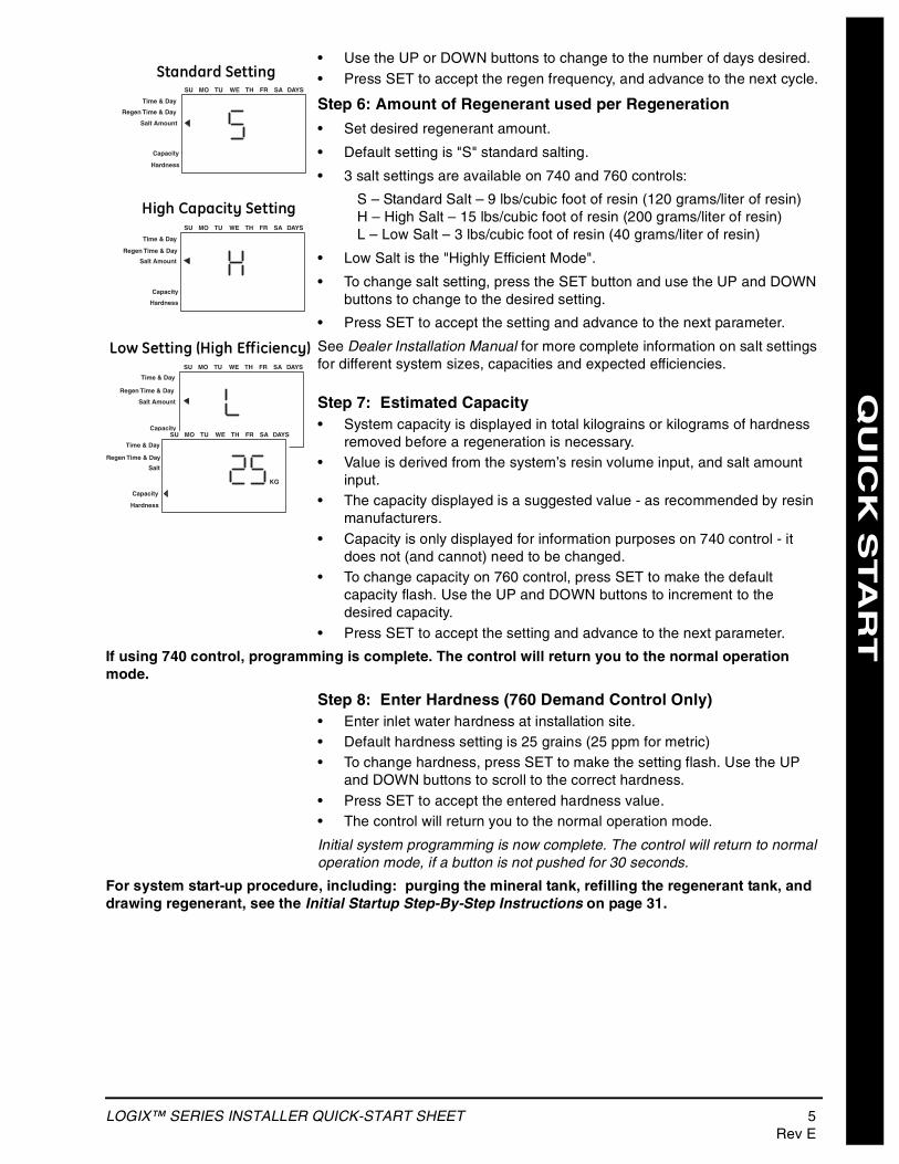
• Use the UP or DOWN buttons to change to the number of days desired.• Press SET to accept the regen frequency, and advance to the next cycle.
Step 6: Amount of Regenerant used per Regeneration
• Set desired regenerant amount.
• Default setting is "S" standard salting.
• 3 salt settings are available on 740 and 760 controls:
S – Standard Salt – 9 lbs/cubic foot of resin (120 grams/liter of resin)H – High Salt – 15 lbs/cubic foot of resin (200 grams/liter of resin)L – Low Salt – 3 lbs/cubic foot of resin (40 grams/liter of resin)
• Low Salt is the "Highly Efficient Mode".
• To change salt setting, press the SET button and use the UP and DOWN buttons to change to the desired setting.
• Press SET to accept the setting and advance to the next parameter.
See Dealer Installation Manual for more complete information on salt settings for different system sizes, capacities and expected efficiencies.
Step 7: Estimated Capacity• System capacity is displayed in total kilograins or kilograms of hardness
removed before a regeneration is necessary.• Value is derived from the system’s resin volume input, and salt amount
input.• The capacity displayed is a suggested value - as recommended by resin
manufacturers.• Capacity is only displayed for information purposes on 740 control - it
does not (and cannot) need to be changed.• To change capacity on 760 control, press SET to make the default
capacity flash. Use the UP and DOWN buttons to increment to the desired capacity.
• Press SET to accept the setting and advance to the next parameter.
If using 740 control, programming is complete. The control will return you to the normal operation mode.
Step 8: Enter Hardness (760 Demand Control Only)• Enter inlet water hardness at installation site.• Default hardness setting is 25 grains (25 ppm for metric)• To change hardness, press SET to make the setting flash. Use the UP
and DOWN buttons to scroll to the correct hardness.• Press SET to accept the entered hardness value.• The control will return you to the normal operation mode.
Initial system programming is now complete. The control will return to normal operation mode, if a button is not pushed for 30 seconds.
For system start-up procedure, including: purging the mineral tank, refilling the regenerant tank, and drawing regenerant, see the Initial Startup Step-By-Step Instructions on page 31.
Time & Day
Regen Time & Day
Salt Amount
SU MO TU WE TH FR SA DAYS
Capacity
Hardness
Time & Day
Regen Time & Day
Salt Amount
SU MO TU WE TH FR SA DAYS
Capacity
Hardness
Time & Day
Regen Time & Day
Salt Amount
SU MO TU WE TH FR SA DAYS
Capacity
Hardness
Standard Setting
High Capacity Setting
Low Setting (High Efficiency)
KG
Time & Day
Regen Time & Day
Salt
SU MO TU WE TH FR SA DAYS
Capacity
Hardness
6 LOGIX™ SERIES INSTALLER QUICK-START SHEETRev E
QU
ICK
STA
RT
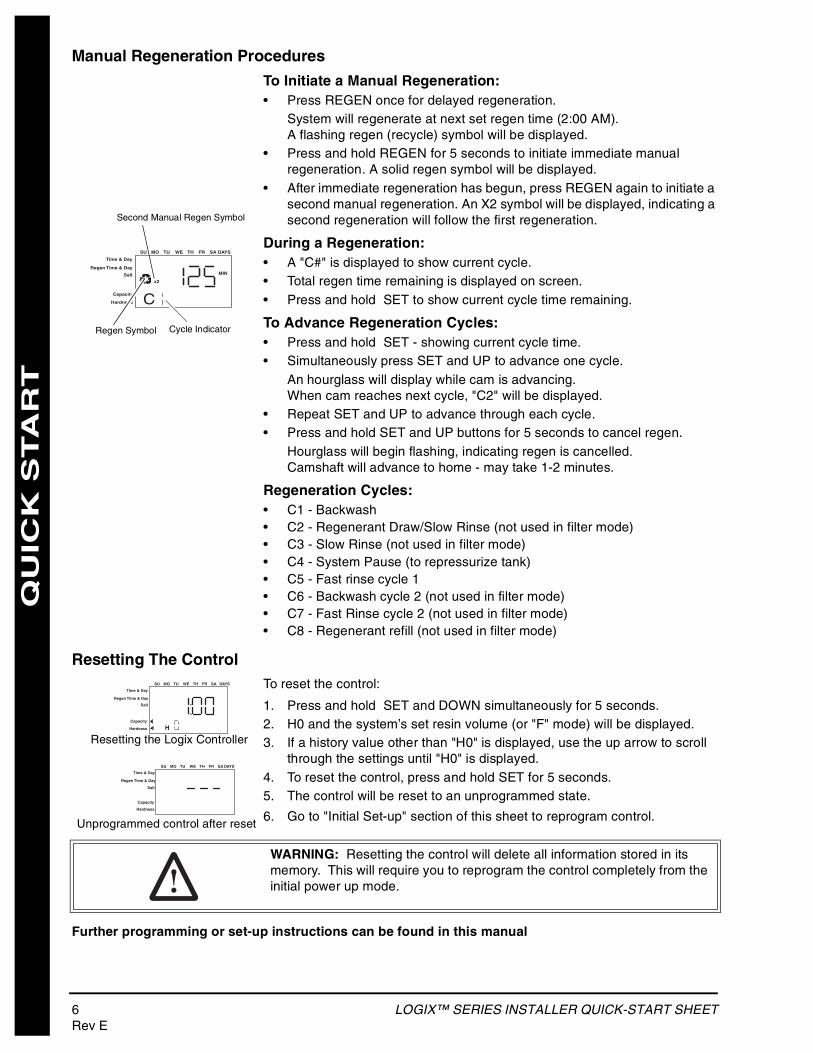
Manual Regeneration Procedures
To Initiate a Manual Regeneration:• Press REGEN once for delayed regeneration.
System will regenerate at next set regen time (2:00 AM).A flashing regen (recycle) symbol will be displayed.
• Press and hold REGEN for 5 seconds to initiate immediate manual regeneration. A solid regen symbol will be displayed.
• After immediate regeneration has begun, press REGEN again to initiate a second manual regeneration. An X2 symbol will be displayed, indicating a second regeneration will follow the first regeneration.
During a Regeneration:• A "C#" is displayed to show current cycle.• Total regen time remaining is displayed on screen.• Press and hold SET to show current cycle time remaining.
To Advance Regeneration Cycles:• Press and hold SET - showing current cycle time.• Simultaneously press SET and UP to advance one cycle.
An hourglass will display while cam is advancing.When cam reaches next cycle, "C2" will be displayed.
• Repeat SET and UP to advance through each cycle.• Press and hold SET and UP buttons for 5 seconds to cancel regen.
Hourglass will begin flashing, indicating regen is cancelled.Camshaft will advance to home - may take 1-2 minutes.
Regeneration Cycles:• C1 - Backwash• C2 - Regenerant Draw/Slow Rinse (not used in filter mode)• C3 - Slow Rinse (not used in filter mode)• C4 - System Pause (to repressurize tank)• C5 - Fast rinse cycle 1• C6 - Backwash cycle 2 (not used in filter mode)• C7 - Fast Rinse cycle 2 (not used in filter mode)• C8 - Regenerant refill (not used in filter mode)
Resetting The ControlTo reset the control:
1. Press and hold SET and DOWN simultaneously for 5 seconds.2. H0 and the system’s set resin volume (or "F" mode) will be displayed.3. If a history value other than "H0" is displayed, use the up arrow to scroll
through the settings until "H0" is displayed.4. To reset the control, press and hold SET for 5 seconds.5. The control will be reset to an unprogrammed state.
6. Go to "Initial Set-up" section of this sheet to reprogram control.
Further programming or set-up instructions can be found in this manual
Time & Day
Regen Time & Day
Salt
SU MO TU WE TH FR SA DAYS
CCapacity
Hardness
MIN
x2
Cycle IndicatorRegen Symbol
Second Manual Regen Symbol
Unprogrammed control after reset
Resetting the Logix Controller
Time & Day
Regen Time & Day
Salt
SU MO TU WE TH FR SA DAYS
HCapacity
Hardness
Time & Day
Regen Time & Day
Salt
SU MO TU WE TH FR SA DAYS
Capacity
Hardness
WARNING: Resetting the control will delete all information stored in its memory. This will require you to reprogram the control completely from the initial power up mode.
MANUAL OVERVIEW 7Rev E
MANUAL OVERVIEW
How To Use This ManualThis installation manual is designed to guide the installer through the process of installing and starting conditioners featuring the 700 Logix series controllers.
This manual is a reference and will not include every system installation situation. The person installing this equipment should have:
• Training in the 700 Logix series controllers and water conditioner installation
• Knowledge of water conditioning and how to determine proper control settings
• Basic plumbing skills
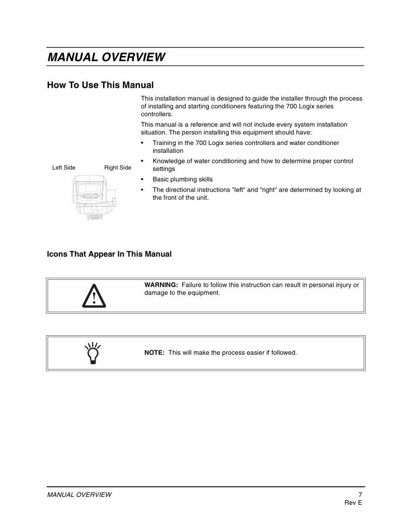
• The directional instructions "left" and “right" are determined by looking at the front of the unit.
Icons That Appear In This Manual
Left Side Right Side
WARNING: Failure to follow this instruction can result in personal injury or damage to the equipment.
NOTE: This will make the process easier if followed.
8 EQUIPMENT INSTALLATIONRev E
EQUIPMENT INSTALLATION
General Warnings And Safety InformationThe 268 and 255 water conditioner’s control valve conforms to NSF/ANSI 44 and 61 for materials and structural integrity only. Generic systems were tested and certified by WQA as verified by the performance data sheet.
ElectricalThere are no user-serviceable parts in the AC adapter, motor, or controller. In the event of a failure, these should be replaced.
• All electrical connections must be completed according to local codes.
• Use only the power AC adapter that is supplied.
• The power outlet must be grounded.
• To disconnect power, unplug the AC adapter from its power source.
Mechanical• Do not use petroleum based lubricants such as vaseline, oils, or
hydrocarbon based lubricants. Use only 100% silicone lubricants.
• All plastic connections should be hand tightened. Teflon tape may be used on connections that do not use an O-ring seal. Do not use pliers or pipe wrenches.
• All plumbing must be completed according to local codes.
• Soldering near the drain line should be done before connecting the drain line to the valve. Excessive heat will cause interior damage to the valve.
• Observe drain line requirements.
• Do not use lead-based solder for sweat solder connections.
• The drain line must be a minimum of 1/2-inch diameter. Use 3/4-inch pipe if the backwash flow rate is greater than 7 GPM (26.5 Lpm) or the pipe length is greater than 20 feet (6 m).
• Do not support the weight of the system on the control valve fittings, plumbing, or the bypass.
• It is not recommended to use sealants on the threads. Use Teflon* tape on the threads of the 1-inch NPT elbow, the drain line connections, and other NPT threads.
*Teflon is a trademark of E.I. duPont de Nemours.
TEST
EDAND CERTIF
IED
UNDER
INDUSTRY ST
AN
DARDS
EQUIPMENT INSTALLATION 9Rev E
General• Observe all warnings that appear in this manual.
• Keep the media tank in the upright position. Do not turn on side, upside down, or drop. Turning the tank upside down will cause media to enter the valve.
• Operating ambient temperature is between 34°F (1°C) and 120°F (49°C).
• Operating water temperature is between 34°F (1°F) and 100°F (38°C).
• Working water pressure range is 20 to 120 psi (1.38 to 8.27 bar). In Canada the acceptable working water pressure range is 20 to 100 psi (1.38 to 6.89 bar).
• Use only regenerant salts designed for water softening. Do not use ice melting, block, or rock salts.
• Follow state and local codes for water testing. Do not use water that is micro biologically unsafe or of unknown quality.
• When filling media tank, do not open water valve completely. Fill tank slowly to prevent media from exiting the tank.
• When installing the water connection (bypass or manifold) connect to the plumbing system first. Allow heated parts to cool and cemented parts to set before installing any plastic parts. Do not get primer or solvent on O-rings, nuts, or the valve.
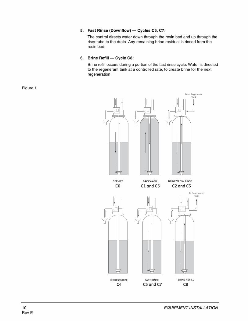
System Regeneration Cycles (7-Cycle Operation)1. Service (Downflow) — Cycle C0:
Untreated water is directed down through the resin bed and up through the riser tube. The hardness ions attach themselves to the resin and are removed from the water. The water is conditioned as it passes through the resin bed.
2. Backwash (Upflow) — Cycles C1, C6:
The flow of water is reversed by the control valve and directed down the riser tube and up through the resin bed. During the backwash cycle, the bed is expanded and debris is flushed to the drain.
3. Brine/Slow Rinse (Downflow) — Cycles C2, C3:
The control directs water through the brine injector and brine is drawn from the regenerant tank. The brine is then directed down through the resin bed and up through the riser tube to the drain. The hardness ions are displaced by sodium ions and are sent to the drain. The resin is regenerated during the brine cycle. Brine draw is completed when the air check closes.
4. Repressurize Cycle — (Hard Water Bypass Flapper Open), Cycle C4:
This cycle closes the flappers for a short time to allow the air and water to hydraulically balance in the valve before continuing the regeneration.
10 EQUIPMENT INSTALLATIONRev E
5. Fast Rinse (Downflow) — Cycles C5, C7:
The control directs water down through the resin bed and up through the riser tube to the drain. Any remaining brine residual is rinsed from the resin bed.
6. Brine Refill — Cycle C8:
Brine refill occurs during a portion of the fast rinse cycle. Water is directed to the regenerant tank at a controlled rate, to create brine for the next regeneration.
Figure 1
SERVICE BACKWASH BRINE/SLOW RINSE
FAST RINSE
From RegenerantTank
To Regenerant Tank
BRINE REFILLREPRESSURIZE
C0 C1 and C6 C2 and C3
C4 C5 and C7 C8
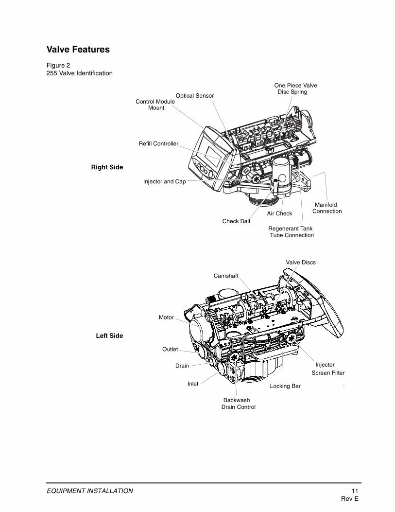
EQUIPMENT INSTALLATION 11Rev E
Valve Features
Figure 2255 Valve Identification
Check BallAir Check
Regenerant Tank
Refill Controller
Injector and Cap
Outlet
Inlet
Drain
Backwash
Locking Bar
Injector
Valve Discs
Camshaft
Drain Control
Screen Filter
Manifold
Motor
Optical SensorControl Module
Mount
One Piece Valve
Tube Connection
Connection
Disc Spring
Right Side
Left Side
12 EQUIPMENT INSTALLATIONRev E
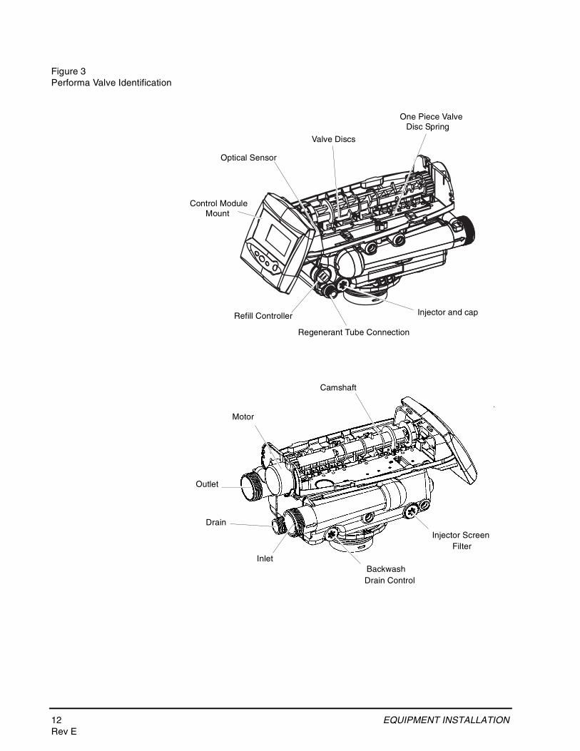
Figure 3Performa Valve Identification
Refill Controller
Regenerant Tube Connection
Injector and cap
Valve Discs
Outlet
Drain
InletBackwash
Injector Screen
Camshaft
Drain Control
Filter
Control ModuleMount
One Piece ValveDisc Spring
Motor
Optical Sensor
EQUIPMENT INSTALLATION 13Rev E
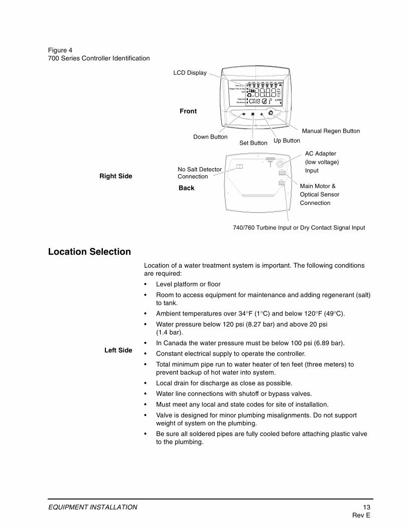
Figure 4700 Series Controller Identification
Location SelectionLocation of a water treatment system is important. The following conditions are required:
• Level platform or floor
• Room to access equipment for maintenance and adding regenerant (salt) to tank.
• Ambient temperatures over 34°F (1°C) and below 120°F (49°C).
• Water pressure below 120 psi (8.27 bar) and above 20 psi (1.4 bar).
• In Canada the water pressure must be below 100 psi (6.89 bar).
• Constant electrical supply to operate the controller.
• Total minimum pipe run to water heater of ten feet (three meters) to prevent backup of hot water into system.
• Local drain for discharge as close as possible.
• Water line connections with shutoff or bypass valves.
• Must meet any local and state codes for site of installation.
• Valve is designed for minor plumbing misalignments. Do not support weight of system on the plumbing.
• Be sure all soldered pipes are fully cooled before attaching plastic valve to the plumbing.
Time & Day
Regen Time & Day
Salt
SU MO TU WE TH FR SA DAYS
LBS
PMMIN
KG
x100x2
PHC
Capacity
Hardness
LCD Display
Manual Regen ButtonDown Button
Set Button Up Button
740/760 Turbine Input or Dry Contact Signal Input
Main Motor & Optical Sensor Connection
AC Adapter (low voltage) Input
Front
Back
No Salt DetectorConnectionRight Side
Left Side
14 EQUIPMENT INSTALLATIONRev E
Outdoor LocationsWhen the water conditioning system is installed outdoors, several items must be considered.
• Moisture — The valve and 700 controller are rated for NEMA 3 locations. Falling water should not affect performance.The system is not designed to withstand extreme humidity or water spray from below. Examples are: constant heavy mist, near corrosive environment, upwards spray from sprinkler.
• Direct Sunlight — The materials used will fade or discolor over time in direct sunlight. The integrity of the materials will not degrade to cause system failures.If it is necessary to locate the conditioner in direct sunlight, a protective outdoor cover (P/N 1267811) over the valve and controller is necessary.
• Temperature — Extreme hot or cold temperatures may cause damage to the valve or controller.Freezing temperatures will freeze the water in the valve. This will cause physical damage to the internal parts as well as the plumbing.High temperatures will affect the controller. The display may become unreadable but the controller should continue to function. When the temperature drops down into normal operating limits the display will return to normal. A protective cover (P/N 1267811) should assist with high temperature applications.
• Insects — The controller and valve have been designed to keep all but the smallest insects out of the critical areas. Any holes in the top plate can be covered with a metal foil duct work tape. The top cover should be installed securely in place.
• Wind — The Logix cover is designed to withstand a 30 mph (48 Kph) wind when properly installed on the valve.
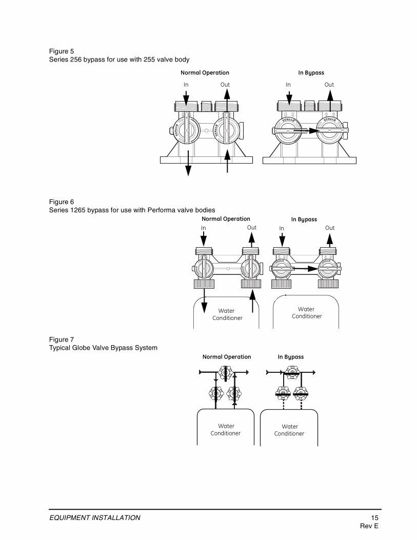
Water Line ConnectionA bypass valve system should be installed on all water conditioning systems. Bypass valves isolate the conditioner from the water system and allow unconditioned water to be used. Service or routine maintenance procedures may also require that the system is bypassed. Figures 5, 6, and 7 show the three common bypass methods.
EQUIPMENT INSTALLATION 15Rev E
Figure 5Series 256 bypass for use with 255 valve body
Figure 6Series 1265 bypass for use with Performa valve bodies
Figure 7Typical Globe Valve Bypass System
Normal Operation In Bypass
BYPASS BYPASS
BY
PA
SS
BY
PA
SS
In Out In Out
Normal Operation In Bypass
BYPASSBYPASS
BY
PA
SS
BY
PA
SS
WaterConditioner
In Out
WaterConditioner
In Out
WaterC
WaterC di i
Normal Operation In Bypass
WaterConditioner
WaterConditioner
16 EQUIPMENT INSTALLATIONRev E
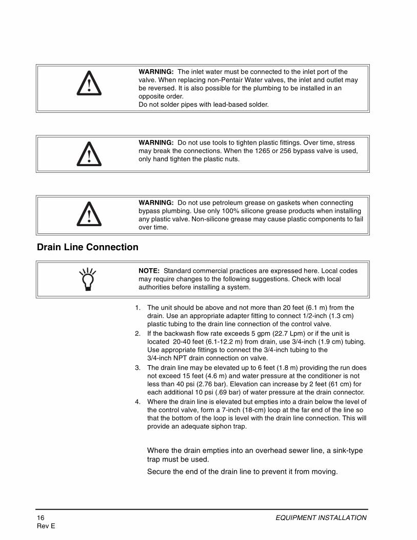
Drain Line Connection
1. The unit should be above and not more than 20 feet (6.1 m) from the drain. Use an appropriate adapter fitting to connect 1/2-inch (1.3 cm) plastic tubing to the drain line connection of the control valve.
2. If the backwash flow rate exceeds 5 gpm (22.7 Lpm) or if the unit is located 20-40 feet (6.1-12.2 m) from drain, use 3/4-inch (1.9 cm) tubing. Use appropriate fittings to connect the 3/4-inch tubing to the3/4-inch NPT drain connection on valve.
3. The drain line may be elevated up to 6 feet (1.8 m) providing the run does not exceed 15 feet (4.6 m) and water pressure at the conditioner is not less than 40 psi (2.76 bar). Elevation can increase by 2 feet (61 cm) for each additional 10 psi (.69 bar) of water pressure at the drain connector.
4. Where the drain line is elevated but empties into a drain below the level of the control valve, form a 7-inch (18-cm) loop at the far end of the line so that the bottom of the loop is level with the drain line connection. This will provide an adequate siphon trap.
Where the drain empties into an overhead sewer line, a sink-type trap must be used.
Secure the end of the drain line to prevent it from moving.
WARNING: The inlet water must be connected to the inlet port of the valve. When replacing non-Pentair Water valves, the inlet and outlet may be reversed. It is also possible for the plumbing to be installed in an opposite order.Do not solder pipes with lead-based solder.
WARNING: Do not use tools to tighten plastic fittings. Over time, stress may break the connections. When the 1265 or 256 bypass valve is used, only hand tighten the plastic nuts.
WARNING: Do not use petroleum grease on gaskets when connecting bypass plumbing. Use only 100% silicone grease products when installing any plastic valve. Non-silicone grease may cause plastic components to fail over time.
NOTE: Standard commercial practices are expressed here. Local codes may require changes to the following suggestions. Check with local authorities before installing a system.
EQUIPMENT INSTALLATION 17Rev E
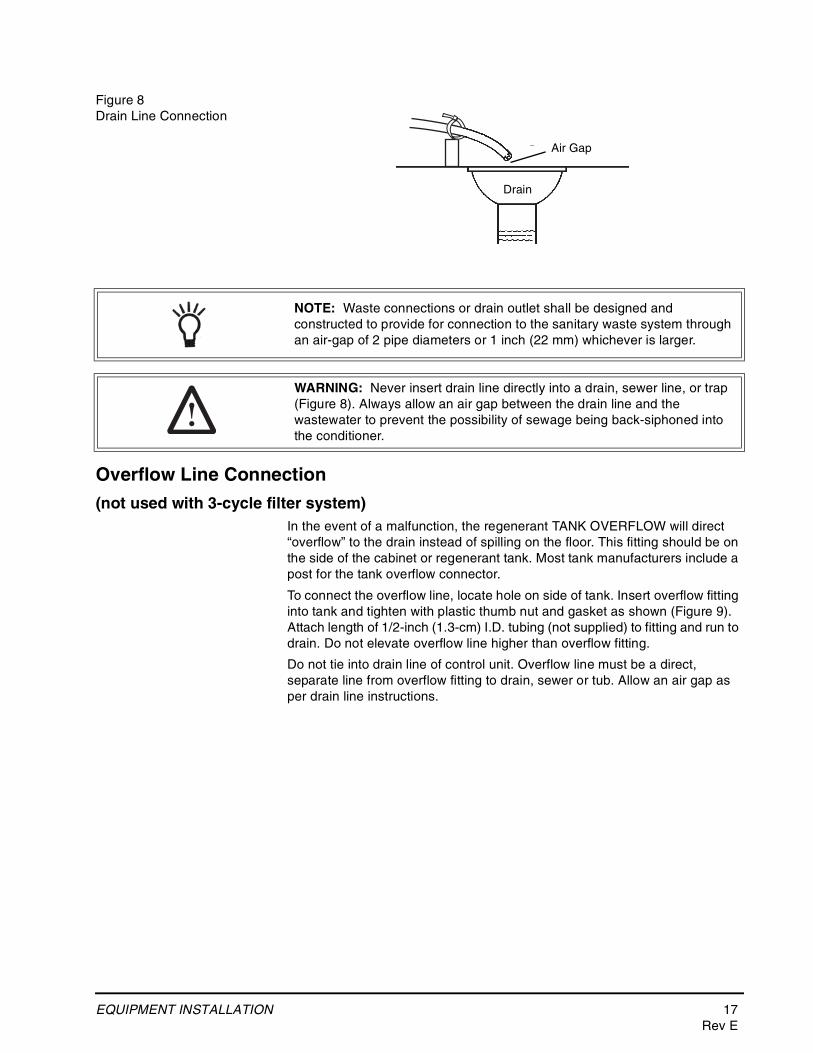
Figure 8Drain Line Connection
Overflow Line Connection
(not used with 3-cycle filter system)In the event of a malfunction, the regenerant TANK OVERFLOW will direct “overflow” to the drain instead of spilling on the floor. This fitting should be on the side of the cabinet or regenerant tank. Most tank manufacturers include a post for the tank overflow connector.
To connect the overflow line, locate hole on side of tank. Insert overflow fitting into tank and tighten with plastic thumb nut and gasket as shown (Figure 9). Attach length of 1/2-inch (1.3-cm) I.D. tubing (not supplied) to fitting and run to drain. Do not elevate overflow line higher than overflow fitting.
Do not tie into drain line of control unit. Overflow line must be a direct, separate line from overflow fitting to drain, sewer or tub. Allow an air gap as per drain line instructions.
Right WayAir Gap
Drain
NOTE: Waste connections or drain outlet shall be designed and constructed to provide for connection to the sanitary waste system through an air-gap of 2 pipe diameters or 1 inch (22 mm) whichever is larger.
WARNING: Never insert drain line directly into a drain, sewer line, or trap (Figure 8). Always allow an air gap between the drain line and the wastewater to prevent the possibility of sewage being back-siphoned into the conditioner.
18 EQUIPMENT INSTALLATIONRev E
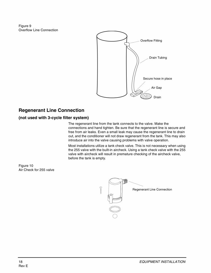
Figure 9Overflow Line Connection
Regenerant Line Connection
(not used with 3-cycle filter system)The regenerant line from the tank connects to the valve. Make the connections and hand tighten. Be sure that the regenerant line is secure and free from air leaks. Even a small leak may cause the regenerant line to drain out, and the conditioner will not draw regenerant from the tank. This may also introduce air into the valve causing problems with valve operation.
Most installations utilize a tank check valve. This is not necessary when using the 255 valve with the built-in aircheck. Using a tank check valve with the 255 valve with aircheck will result in premature checking of the aircheck valve, before the tank is empty.
Figure 10Air Check for 255 valve
Overflow Fitting
Drain Tubing
Air Gap
Drain
Secure hose in place
Regenerant Line Connection
EQUIPMENT INSTALLATION 19Rev E
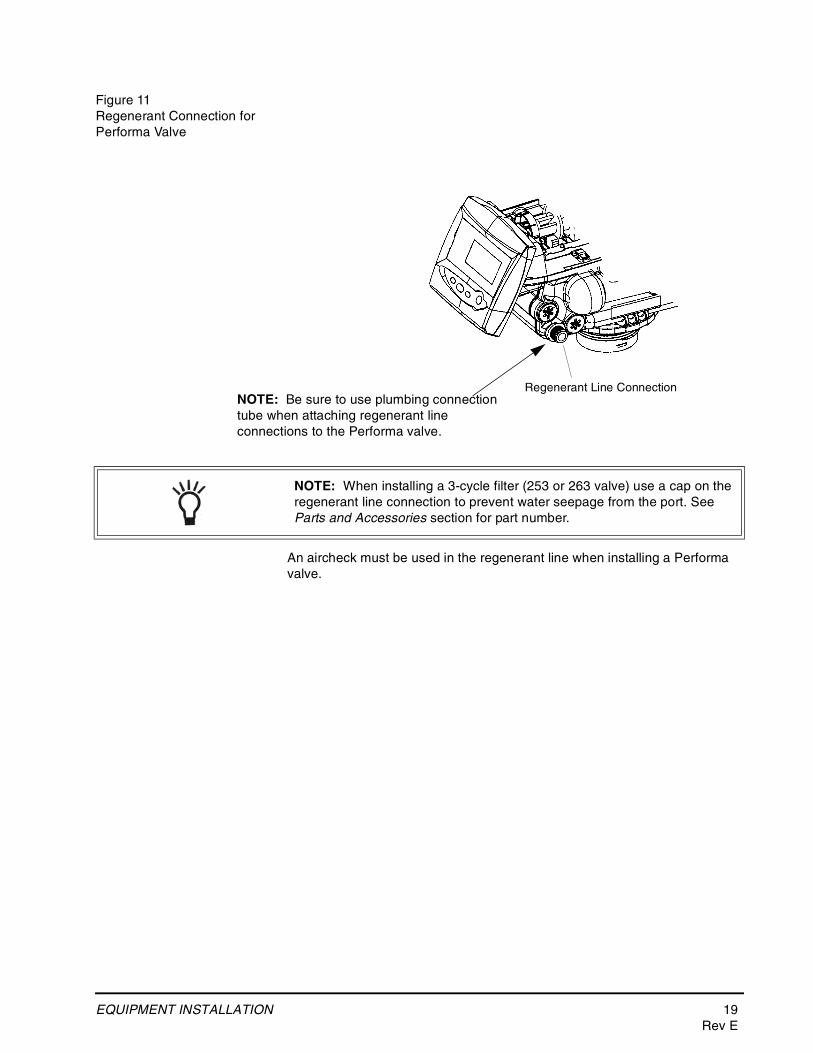
Figure 11Regenerant Connection for Performa Valve
An aircheck must be used in the regenerant line when installing a Performa valve.
NOTE: When installing a 3-cycle filter (253 or 263 valve) use a cap on the regenerant line connection to prevent water seepage from the port. See Parts and Accessories section for part number.
Regenerant Line ConnectionNOTE: Be sure to use plumbing connection tube when attaching regenerant line connections to the Performa valve.
20 EQUIPMENT INSTALLATIONRev E
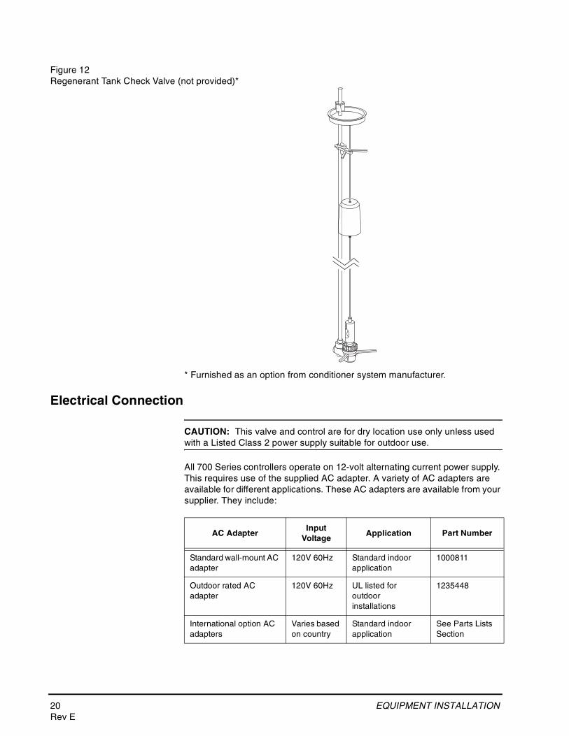
Figure 12 Regenerant Tank Check Valve (not provided)*
* Furnished as an option from conditioner system manufacturer.
Electrical Connection
CAUTION: This valve and control are for dry location use only unless used with a Listed Class 2 power supply suitable for outdoor use.
All 700 Series controllers operate on 12-volt alternating current power supply. This requires use of the supplied AC adapter. A variety of AC adapters are available for different applications. These AC adapters are available from your supplier. They include:
AC AdapterInput
VoltageApplication Part Number
Standard wall-mount AC adapter
120V 60Hz Standard indoor application
1000811
Outdoor rated AC adapter
120V 60Hz UL listed for outdoor installations
1235448
International option AC adapters
Varies based on country
Standard indoor application
See Parts Lists Section
EQUIPMENT INSTALLATION 21Rev E
100 VAC, 120 VAC and 230 VAC AC Adapters:Make sure power source matches the rating printed on the AC adapter.
The 700 Series controller is available in two power configurations. The North American controller operates on 60 Hz. If the incoming power is 50 Hz, the "North American" controller will not function. The error code "ERR 2" will show on the display.
The "World" controller will sense the input power as 50 or 60 Hz and operate accordingly.
Controller LocationThe 700 Series controllers are designed to be mounted on the valve or attached to a flat surface. Installations that do not provide easy access to the valve can have the controller mounted for remote operation.
A remote mount connection, P/N 1256257, is available for the 700 Series controller.
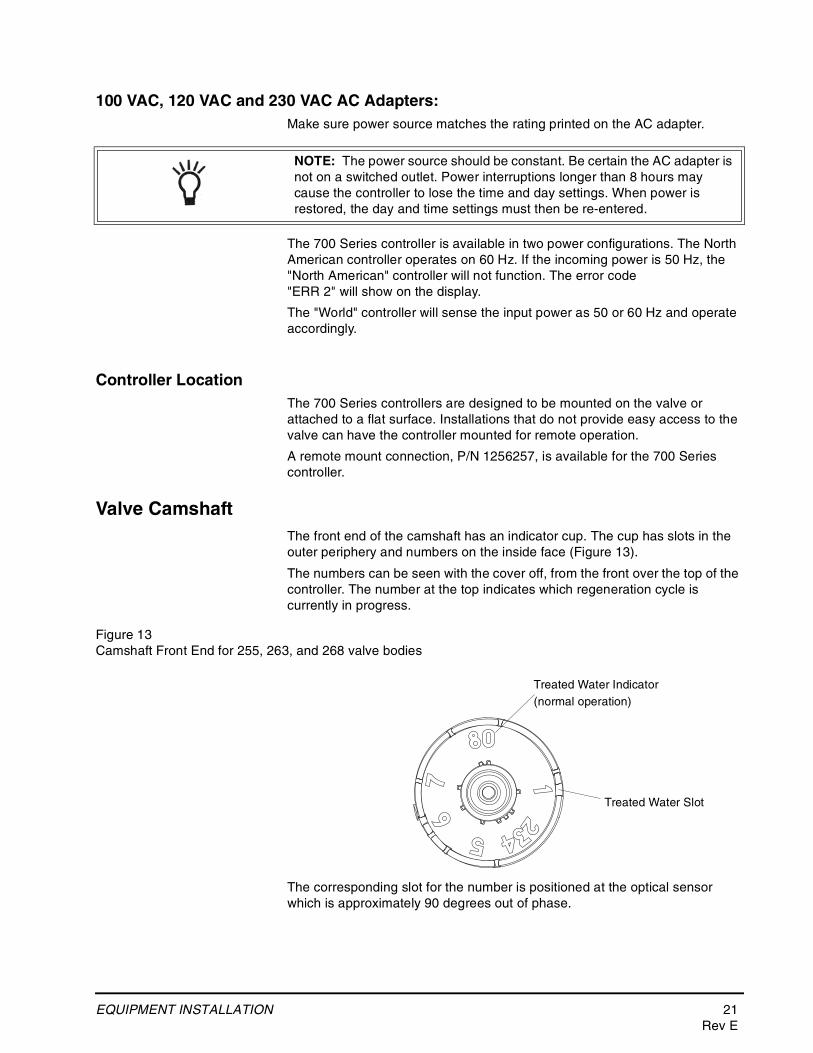
Valve CamshaftThe front end of the camshaft has an indicator cup. The cup has slots in the outer periphery and numbers on the inside face (Figure 13).
The numbers can be seen with the cover off, from the front over the top of the controller. The number at the top indicates which regeneration cycle is currently in progress.
Figure 13Camshaft Front End for 255, 263, and 268 valve bodies
The corresponding slot for the number is positioned at the optical sensor which is approximately 90 degrees out of phase.
NOTE: The power source should be constant. Be certain the AC adapter is not on a switched outlet. Power interruptions longer than 8 hours may cause the controller to lose the time and day settings. When power is restored, the day and time settings must then be re-entered.
Treated Water Slot
Treated Water Indicator(normal operation)
22 EQUIPMENT INSTALLATIONRev E
Regeneration Cycle Indicators
C0 = Treated Water - normal operation modeC1 = Backwash CycleC2 = Regenerant Draw Cycle (not used in filter mode)C3 = Slow Rinse Cycle (not used in filter mode)C4 = System PauseC5 = Fast Rinse Cycle 1C6 = Backwash Cycle 2 (not used in filter mode)C7 = Fast Rinse Cycle 2 (not used in filter mode)C8 = Regenerant Refill (not used in filter mode)
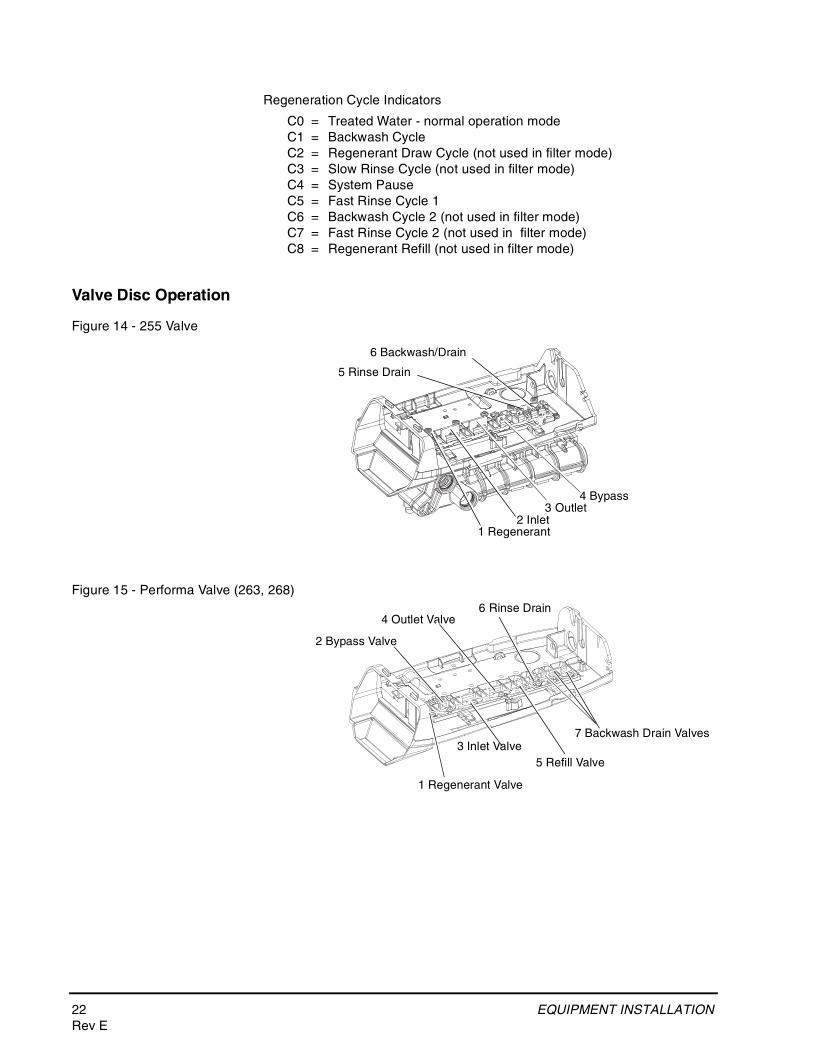
Valve Disc Operation
Figure 14 - 255 Valve
Figure 15 - Performa Valve (263, 268)
1 Regenerant2 Inlet
4 Bypass3 Outlet
5 Rinse Drain
6 Backwash/Drain
1 Regenerant Valve
2 Bypass Valve
3 Inlet Valve
4 Outlet Valve
5 Refill Valve
7 Backwash Drain Valves
6 Rinse Drain
SYSTEM DISINFECTION 23Rev E
SYSTEM DISINFECTION
Disinfection Of Water ConditionersThe materials of construction of the modern water conditioner will not support bacterial growth, nor will these materials contaminate a water supply. During normal use, a conditioner may become fouled with organic matter, or in some cases with bacteria from the water supply. This may result in an off-taste or odor in the water.
Some conditioners may need to be disinfected after installation and some conditioners will require periodic disinfection during their normal life.
Depending upon the conditions of use, the style of conditioner, the type of ion exchanger, and the disinfectant available, a choice can be made among the following methods.
Sodium or Calcium Hypochlorite
Application
These materials are satisfactory for use with polystyrene resins, synthetic gel zeolite, greensand and bentonites.
5.25% Sodium Hypochlorite
These solutions are available under trade names such as Clorox*. If stronger solutions are used, such as those sold for commercial laundries, adjust the dosage accordingly.
1. DosageA. Polystyrene resin; 1.2 fluid ounce (35.5 ml) per cubic foot.
B. Non-resinous exchangers; 0.8 fluid ounce (23.7 ml) per cubic foot.
2. Brine tank conditionersA. Backwash the conditioner and add the required amount of hypochlorite
solution to the well of the regenerant tank. The regenerant tank should have water in it to permit the solution to be carried into the conditioner.
B. Proceed with the normal regeneration.
*Clorox is a trademark of the Clorox Company.
Calcium Hypochlorite
Calcium hypochlorite, 70% available chlorine, is available in several forms including tablets and granules. These solid materials may be used directly without dissolving before use.
1. DosageA. Two grains (approximately 0.1 ounce [3 ml]) per cubic foot.
2. Regenerant tank conditionersA. Backwash the conditioner and add the required amount of hypochlorite
to the well of the regenerant tank. The regenerant tank should have water in it to permit the chlorine solution to be carried into the conditioner.
B. Proceed with the normal regeneration.
24 DETERMINING IF YOU HAVE A 740 OR 760 CON-TROL
DETERMINING IF YOU HAVE A 740 OR 760 CONTROL
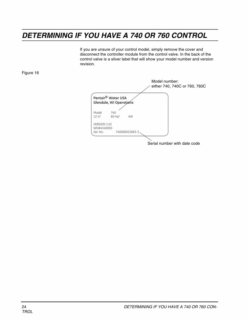
If you are unsure of your control model, simply remove the cover and disconnect the controller module from the control valve. In the back of the control valve is a silver label that will show your model number and version revision.
Figure 16
Pentair Water USAGlendale, WI Operations
Model 74012 V/ 60 Hz/ 4W
VERSION 1.02WO#4340000Ser. No: 740090052683-3
®
Model number:either 740, 740C or 760, 760C
Serial number with date code
GENERAL 700 SERIES INSTRUCTIONS 25Rev E
GENERAL 700 SERIES INSTRUCTIONS
700 SERIES CONTROLLER
Power Loss Memory RetentionThe 700 Series controllers feature battery-free time and date retention during the loss of power. This is designed to last a minimum of 8 hours depending on the installation. The controller will continue to keep time and day in dynamic memory while there is no AC power.
The controller will not track water usage on volumetric demand controls in the event of a power failure.
All programmed parameters are stored in the 700 Series static memory and will not be lost in the event of a power failure. These settings are maintained separately from the time and day settings.
MotorThe 700 series controller uses a standard 12-volt AC motor that works with either 50 Hz or 60 Hz. The same motor is used worldwide and does not need to be changed for different power conditions.
Power700 Series controllers are available in two power configurations:
1. The North American model requires 60 Hz input. The controller will dis-play USA units when power is first applied.
2. The World model accepts either 60 or 50 Hz input and will automatically adjust measurement units when power is first applied.
Information entered or calculated by the controller is stored in two different ways.
A static memory will store:
Media volumeRegenerant setting Time of regenerationDays between regeneration Filter mode
A dynamic memory with 8 hour retention will store:
Current day of weekRunning clock
NOTE: Water flow to the valve can be turned on or bypassed when the controller is powered up for the first time.
26 GENERAL 700 SERIES INSTRUCTIONSRev E
Variable Reserve FunctionThe 700 Series metered-demand volumetric controllers (760 and 760C) are designed to have a variable reserve feature. This feature automatically adjusts the reserve to the end-user’s water usage schedule.
A variable reserve saves salt and water by only regenerating when absolutely necessary, and ensures enough soft water for typical high-water usage days.
Each day of regeneration the controller reviews the last four weeks of water usage for the same day of the week to determine if the remaining capacity is adequate for the next day of the week. If the remaining capacity is not adequate, it will initiate an automatic regeneration.
DISPLAY ICONS 700 CONTROLLER 27Rev E
DISPLAY ICONS 700 CONTROLLER
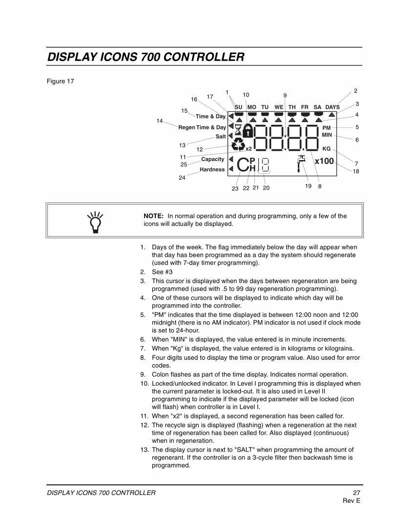
Figure 17
1. Days of the week. The flag immediately below the day will appear when that day has been programmed as a day the system should regenerate (used with 7-day timer programming).
2. See #33. This cursor is displayed when the days between regeneration are being
programmed (used with .5 to 99 day regeneration programming).4. One of these cursors will be displayed to indicate which day will be
programmed into the controller.5. "PM" indicates that the time displayed is between 12:00 noon and 12:00
midnight (there is no AM indicator). PM indicator is not used if clock mode is set to 24-hour.
6. When "MIN" is displayed, the value entered is in minute increments.7. When "Kg" is displayed, the value entered is in kilograms or kilograins.8. Four digits used to display the time or program value. Also used for error
codes.9. Colon flashes as part of the time display. Indicates normal operation.10. Locked/unlocked indicator. In Level I programming this is displayed when
the current parameter is locked-out. It is also used in Level II programming to indicate if the displayed parameter will be locked (icon will flash) when controller is in Level I.
11. When "x2" is displayed, a second regeneration has been called for.12. The recycle sign is displayed (flashing) when a regeneration at the next
time of regeneration has been called for. Also displayed (continuous) when in regeneration.
13. The display cursor is next to "SALT" when programming the amount of regenerant. If the controller is on a 3-cycle filter then backwash time is programmed.
PMMIN
KGx2
Time & Day
Regen Time & Day
Salt
SU MO TU WE TH FR SA DAYS
x100PHCCapacity
Hardness
1 2
3
4
5
6
7
8
910
1112
13
14
15
16 17
18
1920212223
24
25
NOTE: In normal operation and during programming, only a few of the icons will actually be displayed.
28 DISPLAY ICONS 700 CONTROLLERRev E
14. The display cursor is next to "REGEN TIME & DAY" when programming the time of regeneration and the days of regeneration.
15. The display cursor is next to "TIME & DAY" when programming the current time and day.
16. The hourglass is displayed when the motor is running. The camshaft should be turning.
17. These cursors will appear next to the item that is currently displayed.18. X100 multiplier for large values.19. Shows when water is flowing through the valve.20. Used with #24, #25, and #26. Displays a sequence number or a value.21. History Values (H). The number displayed by #23 identifies which history
value is currently displayed.22. Parameter (P). Displayed only in Level II Programming. The number
displayed by #23 identifies which parameter is currently displayed.23. Cycle(C). The number displayed by #23 is the current cycle in the
regeneration sequence.24. Hardness setting—only used with 760 and 760C controllers.25. Capacity display—shows estimated system capacity.
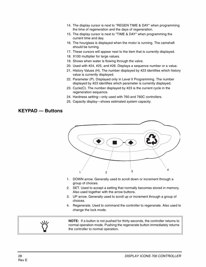
KEYPAD — Buttons
1. DOWN arrow. Generally used to scroll down or increment through a group of choices.
2. SET. Used to accept a setting that normally becomes stored in memory. Also used together with the arrow buttons.
3. UP arrow. Generally used to scroll up or increment through a group of choices.
4. Regenerate. Used to command the controller to regenerate. Also used to change the lock mode.
21 3 4
NOTE: If a button is not pushed for thirty seconds, the controller returns to normal operation mode. Pushing the regenerate button immediately returns the controller to normal operation.
DISPLAY ICONS 700 CONTROLLER 29Rev E
Programming ConventionsThe 700 Series controller is programmed using the buttons on the keypad. The programming instructions will be described two ways whenever a section has keypad input.
First, a table shows simplified instructions. Second, text follows that describes the action. In each table:
"Action" lists the event or action desired.
"Keys" are listed as:
UP for up arrow
DOWN for down arrow
SET for set
REGEN for regeneration
"Duration" describes how long a button is held down:
P/R for press and releaseHOLD for press and holdX sec for a number of seconds to press the button and hold it down"Display" calls out the display icons that are visible.
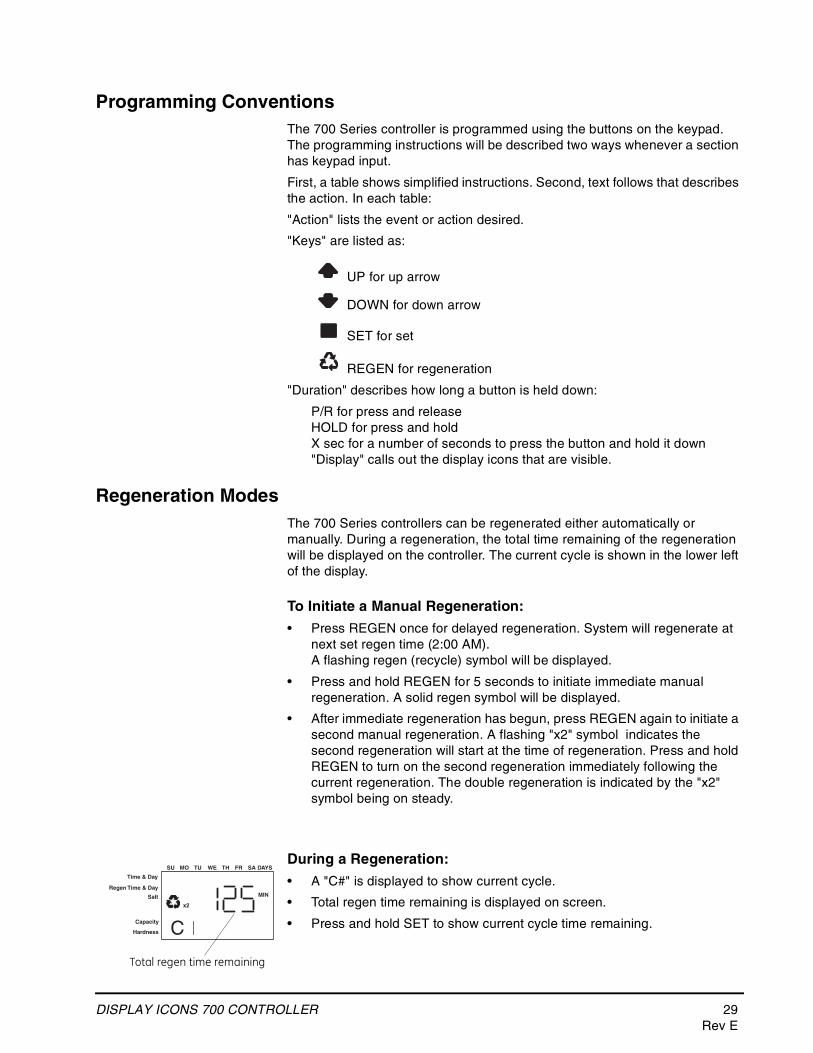
Regeneration ModesThe 700 Series controllers can be regenerated either automatically or manually. During a regeneration, the total time remaining of the regeneration will be displayed on the controller. The current cycle is shown in the lower left of the display.
To Initiate a Manual Regeneration:
• Press REGEN once for delayed regeneration. System will regenerate at next set regen time (2:00 AM).A flashing regen (recycle) symbol will be displayed.
• Press and hold REGEN for 5 seconds to initiate immediate manual regeneration. A solid regen symbol will be displayed.
• After immediate regeneration has begun, press REGEN again to initiate a second manual regeneration. A flashing "x2" symbol indicates the second regeneration will start at the time of regeneration. Press and hold REGEN to turn on the second regeneration immediately following the current regeneration. The double regeneration is indicated by the "x2" symbol being on steady.
During a Regeneration:
• A "C#" is displayed to show current cycle.
• Total regen time remaining is displayed on screen.
• Press and hold SET to show current cycle time remaining.
Time & Day
Regen Time & Day
Salt
SU MO TU WE TH FR SA DAYS
CCapacity
Hardness
MIN
x2
Total regen time remaining
30 DISPLAY ICONS 700 CONTROLLERRev E
To Advance Regeneration Cycles:
• Press and hold SET - showing current cycle time.
• Simultaneously press SET and UP to advance on cycle. An hourglass will display while cam is advancing.When cam reaches next cycle, "C2” will be displayed.
• Repeat SET and UP to advance through each cycle.
• Press and hold SET and UP for 5 seconds to cancel regen.Hourglass will flash once cancelled.Camshaft will advance to home – may take 1 to 2 minutes.
Regeneration Cycles:
• C1 – Backwash
• C2 – Regeneration Draw/Slow Rinse (not used in filter mode)
• C3 – Slow Rinse (not used in filter mode)
• C4 – System Pause (to repressurize tank)
• C5 – Fast Rinse cycle 1
• C6 – Backwash cycle 2 (not used in filter mode)
• C7 – Fast Rinse cycle 2 (not used in filter mode)
• C8 – Regenerant Refill (not used in filter mode)
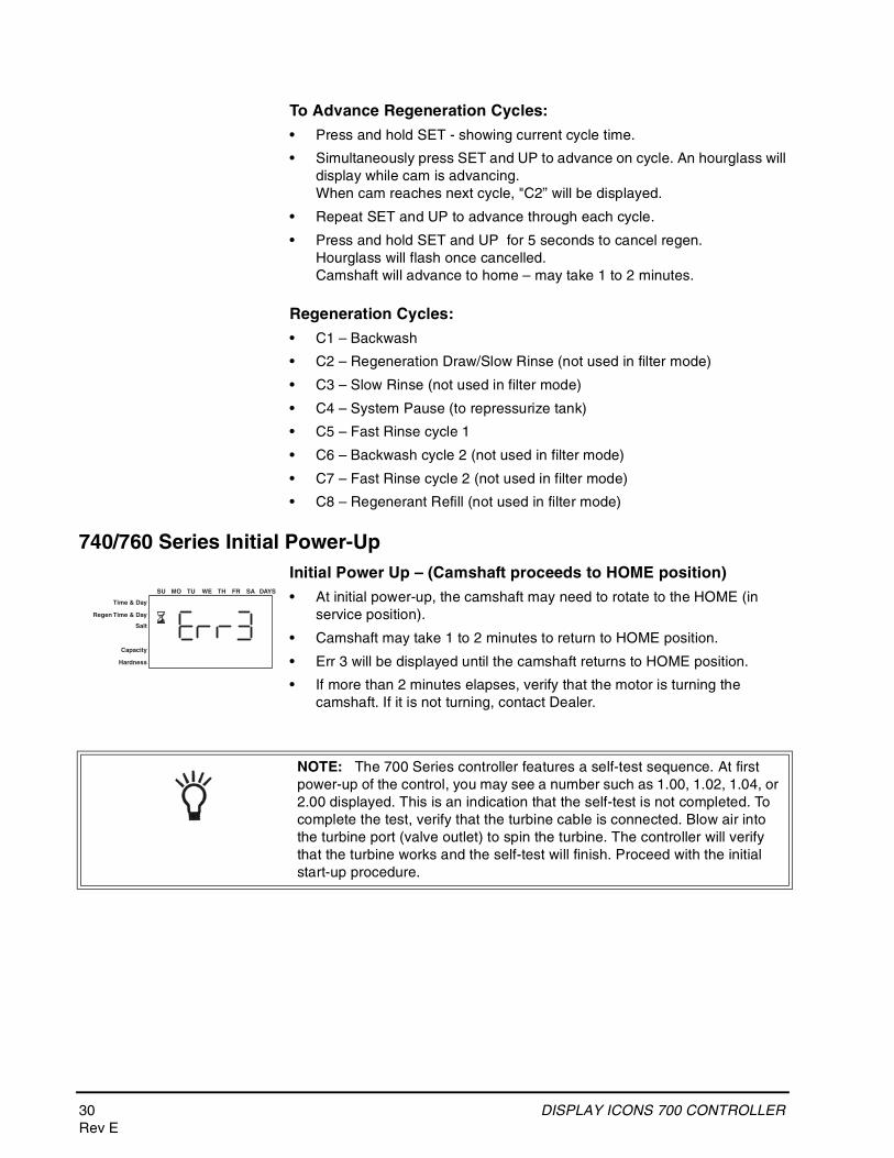
740/760 Series Initial Power-UpInitial Power Up – (Camshaft proceeds to HOME position)
• At initial power-up, the camshaft may need to rotate to the HOME (in service position).
• Camshaft may take 1 to 2 minutes to return to HOME position.
• Err 3 will be displayed until the camshaft returns to HOME position.
• If more than 2 minutes elapses, verify that the motor is turning the camshaft. If it is not turning, contact Dealer.
Time & Day
Regen Time & Day
Salt
Capacity
Hardness
SU MO TU WE TH FR SA DAYS
NOTE: The 700 Series controller features a self-test sequence. At first power-up of the control, you may see a number such as 1.00, 1.02, 1.04, or 2.00 displayed. This is an indication that the self-test is not completed. To complete the test, verify that the turbine cable is connected. Blow air into the turbine port (valve outlet) to spin the turbine. The controller will verify that the turbine works and the self-test will finish. Proceed with the initial start-up procedure.
DISPLAY ICONS 700 CONTROLLER 31Rev E
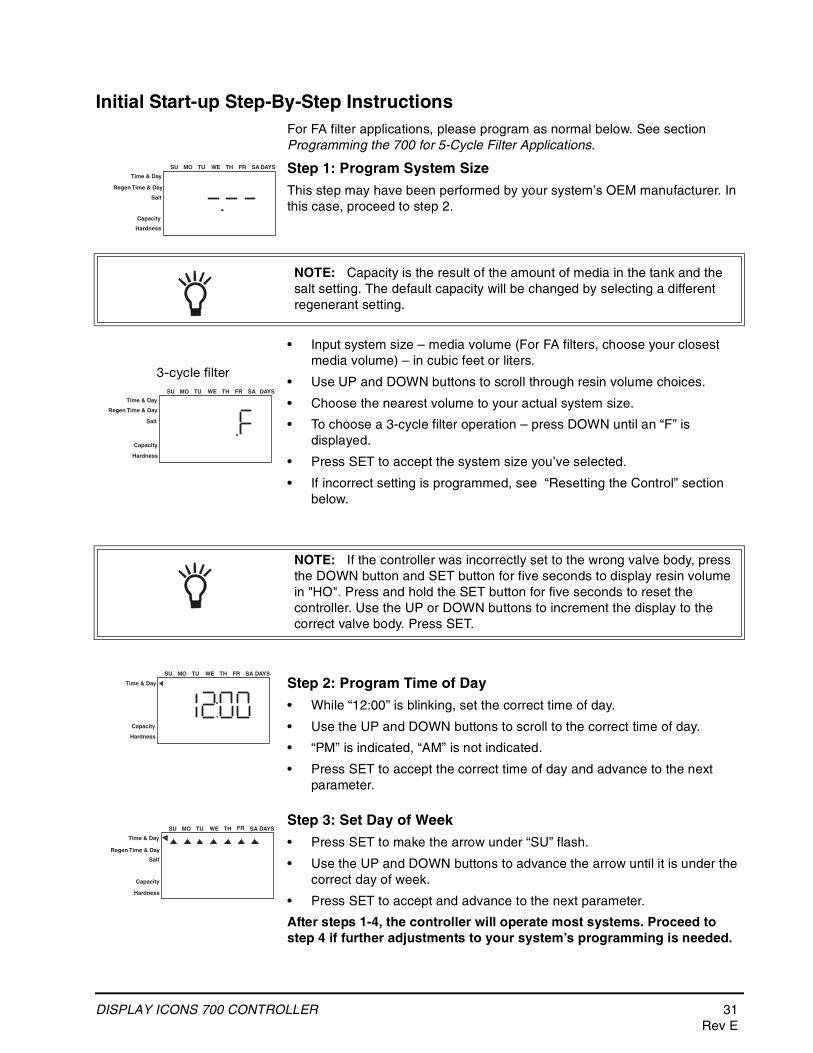
Initial Start-up Step-By-Step InstructionsFor FA filter applications, please program as normal below. See section Programming the 700 for 5-Cycle Filter Applications.
Step 1: Program System Size
This step may have been performed by your system’s OEM manufacturer. In this case, proceed to step 2.
• Input system size – media volume (For FA filters, choose your closest media volume) – in cubic feet or liters.
• Use UP and DOWN buttons to scroll through resin volume choices.
• Choose the nearest volume to your actual system size.
• To choose a 3-cycle filter operation – press DOWN until an “F” is displayed.
• Press SET to accept the system size you’ve selected.
• If incorrect setting is programmed, see “Resetting the Control” section below.
Step 2: Program Time of Day
• While “12:00” is blinking, set the correct time of day.
• Use the UP and DOWN buttons to scroll to the correct time of day.
• “PM” is indicated, “AM” is not indicated.
• Press SET to accept the correct time of day and advance to the next parameter.
Step 3: Set Day of Week
• Press SET to make the arrow under “SU” flash.
• Use the UP and DOWN buttons to advance the arrow until it is under the correct day of week.
• Press SET to accept and advance to the next parameter.
After steps 1-4, the controller will operate most systems. Proceed to step 4 if further adjustments to your system’s programming is needed.
Time & Day
Regen Time & Day
Salt
SU MO TU WE TH FR SA DAYS
Capacity
Hardness
NOTE: Capacity is the result of the amount of media in the tank and the salt setting. The default capacity will be changed by selecting a different regenerant setting.
Time & Day
Regen Time & Day
Salt
SU MO TU WE TH FR SA DAYS
Capacity
Hardness
3-cycle filter
NOTE: If the controller was incorrectly set to the wrong valve body, press the DOWN button and SET button for five seconds to display resin volume in "HO". Press and hold the SET button for five seconds to reset the controller. Use the UP or DOWN buttons to increment the display to the correct valve body. Press SET.
Time & Day
SU MO TU WE TH FR SA DAYS
Capacity
Hardness
Time & Day
Regen Time & Day
Salt
SU MO TU WE TH FR SA DAYS
Capacity
Hardness
32 DISPLAY ICONS 700 CONTROLLERRev E
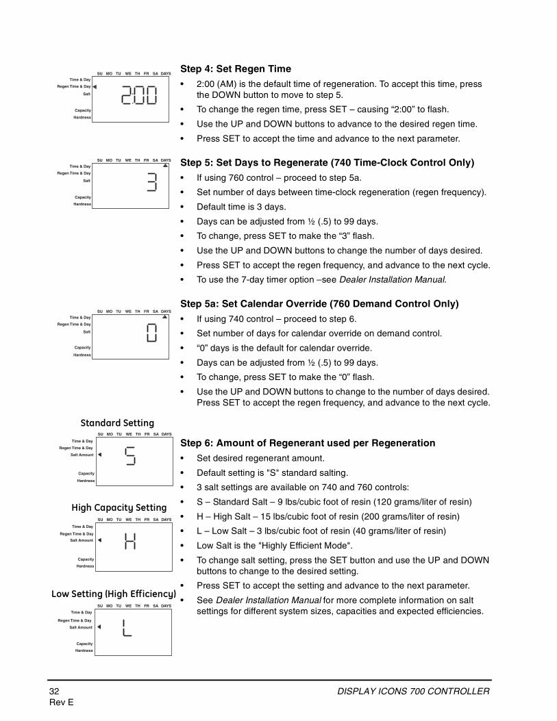
Step 4: Set Regen Time
• 2:00 (AM) is the default time of regeneration. To accept this time, press the DOWN button to move to step 5.
• To change the regen time, press SET – causing “2:00” to flash.
• Use the UP and DOWN buttons to advance to the desired regen time.
• Press SET to accept the time and advance to the next parameter.
Step 5: Set Days to Regenerate (740 Time-Clock Control Only)
• If using 760 control – proceed to step 5a.
• Set number of days between time-clock regeneration (regen frequency).
• Default time is 3 days.
• Days can be adjusted from ½ (.5) to 99 days.
• To change, press SET to make the “3” flash.
• Use the UP and DOWN buttons to change the number of days desired.
• Press SET to accept the regen frequency, and advance to the next cycle.
• To use the 7-day timer option –see Dealer Installation Manual.
Step 5a: Set Calendar Override (760 Demand Control Only)
• If using 740 control – proceed to step 6.
• Set number of days for calendar override on demand control.
• “0” days is the default for calendar override.
• Days can be adjusted from ½ (.5) to 99 days.
• To change, press SET to make the “0” flash.
• Use the UP and DOWN buttons to change to the number of days desired. Press SET to accept the regen frequency, and advance to the next cycle.
Step 6: Amount of Regenerant used per Regeneration
• Set desired regenerant amount.
• Default setting is "S" standard salting.
• 3 salt settings are available on 740 and 760 controls:
• S – Standard Salt – 9 lbs/cubic foot of resin (120 grams/liter of resin)
• H – High Salt – 15 lbs/cubic foot of resin (200 grams/liter of resin)
• L – Low Salt – 3 lbs/cubic foot of resin (40 grams/liter of resin)
• Low Salt is the "Highly Efficient Mode".
• To change salt setting, press the SET button and use the UP and DOWN buttons to change to the desired setting.
• Press SET to accept the setting and advance to the next parameter.
• See Dealer Installation Manual for more complete information on salt settings for different system sizes, capacities and expected efficiencies.
Time & Day
Regen Time & Day
Salt
SU MO TU WE TH FR SA DAYS
Capacity
Hardness
Time & Day
Regen Time & Day
Salt
SU MO TU WE TH FR SA DAYS
Capacity
Hardness
Time & Day
Regen Time & Day
Salt
SU MO TU WE TH FR SA DAYS
Capacity
Hardness
Time & Day
Regen Time & Day
Salt Amount
SU MO TU WE TH FR SA DAYS
Capacity
Hardness
Time & Day
Regen Time & Day
Salt Amount
SU MO TU WE TH FR SA DAYS
Capacity
Hardness
Time & Day
Regen Time & Day
Salt Amount
SU MO TU WE TH FR SA DAYS
Capacity
Hardness
Standard Setting
High Capacity Setting
Low Setting (High Efficiency)
DISPLAY ICONS 700 CONTROLLER 33Rev E
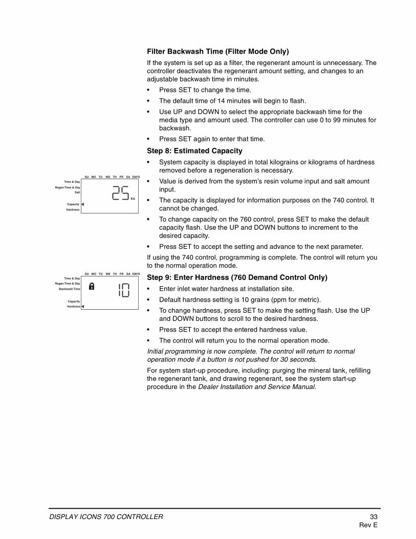
Filter Backwash Time (Filter Mode Only)
If the system is set up as a filter, the regenerant amount is unnecessary. The controller deactivates the regenerant amount setting, and changes to an adjustable backwash time in minutes.
• Press SET to change the time.
• The default time of 14 minutes will begin to flash.
• Use UP and DOWN to select the appropriate backwash time for the media type and amount used. The controller can use 0 to 99 minutes for backwash.
• Press SET again to enter that time.
Step 8: Estimated Capacity
• System capacity is displayed in total kilograins or kilograms of hardness removed before a regeneration is necessary.
• Value is derived from the system’s resin volume input and salt amount input.
• The capacity is displayed for information purposes on the 740 control. It cannot be changed.
• To change capacity on the 760 control, press SET to make the default capacity flash. Use the UP and DOWN buttons to increment to the desired capacity.
• Press SET to accept the setting and advance to the next parameter.
If using the 740 control, programming is complete. The control will return you to the normal operation mode.
Step 9: Enter Hardness (760 Demand Control Only)
• Enter inlet water hardness at installation site.
• Default hardness setting is 10 grains (ppm for metric).
• To change hardness, press SET to make the setting flash. Use the UP and DOWN buttons to scroll to the desired hardness.
• Press SET to accept the entered hardness value.
• The control will return you to the normal operation mode.
Initial programming is now complete. The control will return to normal operation mode if a button is not pushed for 30 seconds.
For system start-up procedure, including: purging the mineral tank, refilling the regenerant tank, and drawing regenerant, see the system start-up procedure in the Dealer Installation and Service Manual.
KG
Time & Day
Regen Time & Day
Salt
SU MO TU WE TH FR SA DAYS
Capacity
Hardness
Time & Day
Regen Time & Day
Backwash Time
SU MO TU WE TH FR SA DAYS
Capacity
Hardness
34 PLACING CONDITIONER INTO OPERATION (turning on the water)
PLACING CONDITIONER INTO OPERATION (turning on the water)
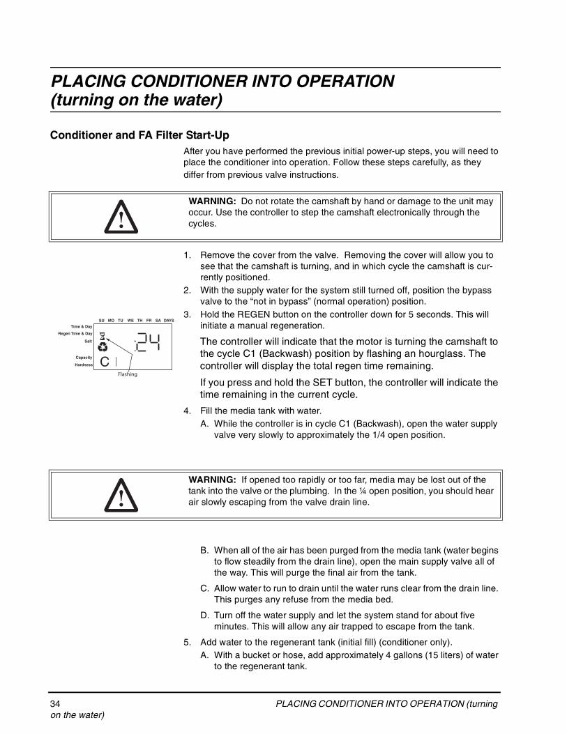
Conditioner and FA Filter Start-UpAfter you have performed the previous initial power-up steps, you will need to place the conditioner into operation. Follow these steps carefully, as they differ from previous valve instructions.
1. Remove the cover from the valve. Removing the cover will allow you to see that the camshaft is turning, and in which cycle the camshaft is cur-rently positioned.
2. With the supply water for the system still turned off, position the bypass valve to the “not in bypass” (normal operation) position.
3. Hold the REGEN button on the controller down for 5 seconds. This will initiate a manual regeneration.
The controller will indicate that the motor is turning the camshaft to the cycle C1 (Backwash) position by flashing an hourglass. The controller will display the total regen time remaining.
If you press and hold the SET button, the controller will indicate the time remaining in the current cycle.
4. Fill the media tank with water.A. While the controller is in cycle C1 (Backwash), open the water supply
valve very slowly to approximately the 1/4 open position.
B. When all of the air has been purged from the media tank (water begins to flow steadily from the drain line), open the main supply valve all of the way. This will purge the final air from the tank.
C. Allow water to run to drain until the water runs clear from the drain line. This purges any refuse from the media bed.
D. Turn off the water supply and let the system stand for about five minutes. This will allow any air trapped to escape from the tank.
5. Add water to the regenerant tank (initial fill) (conditioner only).A. With a bucket or hose, add approximately 4 gallons (15 liters) of water
to the regenerant tank.
WARNING: Do not rotate the camshaft by hand or damage to the unit may occur. Use the controller to step the camshaft electronically through the cycles.
Time & Day
Regen Time & Day
Salt
SU MO TU WE TH FR SA DAYS
CCapacity
Hardness
Flashing
WARNING: If opened too rapidly or too far, media may be lost out of the tank into the valve or the plumbing. In the ¼ open position, you should hear air slowly escaping from the valve drain line.
PLACING CONDITIONER INTO OPERATION (turning on the water) 35Rev E
If the tank has a salt platform in the bottom of the tank, add water until the water level is approximately 1 inch (25 mm) above the platform.
6. Engage the refill cycle to prime the line between the regenerant tank and the valve (conditioner only).A. Slowly open the main water supply valve again, to the fully open
position. Be sure not to open too rapidly as that would push the media out of the media tank.
B. Advance the controller to the Refill (C8) position. From cycle C1 (Backwash), press and hold the SET button. This will display the current cycle.
While pressing the SET button, press UP to advance to the next cycle. Continue to advance through each cycle until you have reached cycle C8 (Refill).
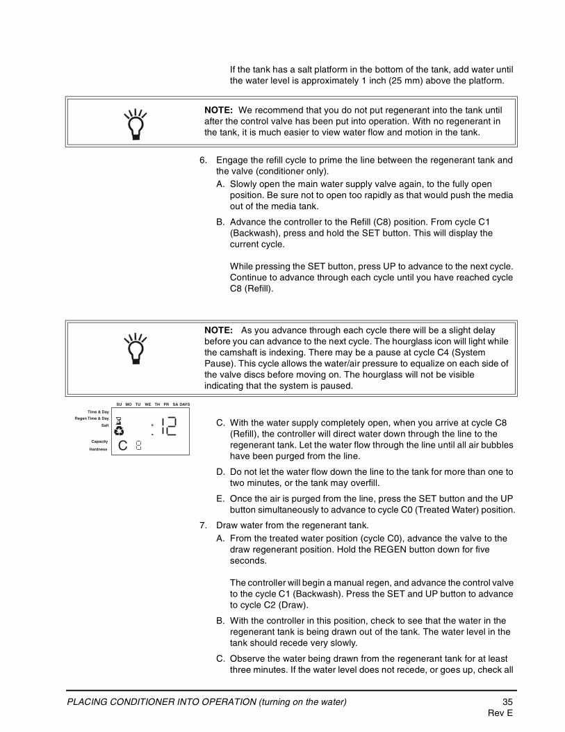
C. With the water supply completely open, when you arrive at cycle C8 (Refill), the controller will direct water down through the line to the regenerant tank. Let the water flow through the line until all air bubbles have been purged from the line.
D. Do not let the water flow down the line to the tank for more than one to two minutes, or the tank may overfill.
E. Once the air is purged from the line, press the SET button and the UP button simultaneously to advance to cycle C0 (Treated Water) position.
7. Draw water from the regenerant tank.A. From the treated water position (cycle C0), advance the valve to the
draw regenerant position. Hold the REGEN button down for five seconds.
The controller will begin a manual regen, and advance the control valve to the cycle C1 (Backwash). Press the SET and UP button to advance to cycle C2 (Draw).
B. With the controller in this position, check to see that the water in the regenerant tank is being drawn out of the tank. The water level in the tank should recede very slowly.
C. Observe the water being drawn from the regenerant tank for at least three minutes. If the water level does not recede, or goes up, check all
NOTE: We recommend that you do not put regenerant into the tank until after the control valve has been put into operation. With no regenerant in the tank, it is much easier to view water flow and motion in the tank.
NOTE: As you advance through each cycle there will be a slight delay before you can advance to the next cycle. The hourglass icon will light while the camshaft is indexing. There may be a pause at cycle C4 (System Pause). This cycle allows the water/air pressure to equalize on each side of the valve discs before moving on. The hourglass will not be visible indicating that the system is paused.
Time & Day
Regen Time & Day
Salt
SU MO TU WE TH FR SA DAYS
CCapacity
Hardness
36 PLACING CONDITIONER INTO OPERATION (turning on the water)
hose connections. C2 should be displayed.
8. If the water level is receding from the regenerant tank you can then advance the controller back to the treated water (C0) position by pressing SET and the UP buttons simultaneously to advance the controller to the C0 position.
9. Finally, turn on a faucet plumbed after the water conditioner. Run the faucet until the water runs clear. Add regenerant to the regenerant tank.
Things You Might Need to Know
• When the controller is first plugged in, it may display a flashing hourglass and the message Err 3, this means that the controller is rotating to the home position. If the Err 2 is displayed, check that the incoming power frequency matches the controller. The North American controller will not run with 50 Hz input.
• The preset default time of regeneration is 2:00 AM.
• English or Metric? The World controller senses the electrical input and decides which is needed. The North American controller only runs on 60 Hz and defaults to English units.
• The 700 Series controller can be programmed to regenerate on specific days of the week.
• If electrical power is not available, the camshaft can be rotated counterclockwise by hand if the motor is removed.
• The 700 Series controllers send commands to the motor for camshaft movement. However, water pressure/flow are required during the regeneration cycle for backwash, purge and refill, and brine draw to actually take place.
• Make sure control power source is plugged in. The transformer should be connected to a non-switched power source.
• You can start programming at the beginning by resetting the amount of media. When viewing H0 (History Value) push and hold SET for five seconds. The display reverts back to --- and any programmed information is lost. Return to 700 Series Initial Power Up.
PROGRAMMING THE 700 FOR 5-CYCLE FILTER APPLICATIONS 37Rev E
PROGRAMMING THE 700 FOR 5-CYCLE FILTER APPLICATIONS
Manganese Greensand Systems
Sizing FA FiltersPotassium permanganate regenerating iron filters should be sized for the appropriate backwash and injector sizes.
Backwash Controller
Be sure to choose the appropriate backwash flow rate control (see Parts section) as recommended by your media manufacturer.
Injector
Use the same injector size as you would for your conditioner control tank diameter.
Refill Controller
A FA filter can use the 0.33 gpm refill control that is featured as standard with a Logix controller. Use a check valve in your potassium permanganate feeder to prevent overflow.
Initial Resin Volume SettingProgramming for a manganese greensand system requires a few minor adjustments to the programming to operate the control correctly. The initial resin volume should be set to the closest volume of the manganese greensand in the system. For example, if the system contains two cubic feet of manganese greensand, program in 2.00 for the resin volume.
"Salt" Setting for KMNO3 Regenerant
Since the same injector is used for the filter application (FA) system and the conditioner system, be sure the regenerant (salt) setting is set to High “H” to allow adequate time to rinse the media.
All other settings will remain the same as mentioned in the previous programming sections.
Days Between Regeneration Setting (740 FA)To set the days between regenerations, consult the media manufacturer for the actual capacity of the media.
In general, manganese greensand has a capacity of 10,000 ppm of removal capability per cubic foot of media. Calculate the capacity of the system by taking the number of cubic feet of media and multiply by 10,000.
For example, using a 1 cubic foot system provides 10,000 ppm of removal capability.
The next step is to calculate the demand for the system. Multiply the predicted daily water usage by the iron content in ppm.
For example, an average person uses 75 gallons of water per day. Four people living in a home use 300 gallons of water (75 gallons x 4 people) per day. Assume the incoming water has 10 ppm of iron. Now calculate the daily
38 PROGRAMMING THE 700 FOR 5-CYCLE FILTER AP-PLICATIONS
demand: multiply the gallons of water used per day (300) by the ppm of iron content (10) = 3000 ppm of daily capacity usage.
Now take the system capacity (10,000), divided by the daily demand (3,000) = 3.3 days of capacity. Since you will run out of capacity before the beginning of the fourth day, the proper setting for days between regeneration is 3 days.
For example:
4 people x 75 gals per person = 300 gallons used per day.
10 ppm iron x 300 gal/day = 3000 ppm/day
10,000 ppm capacity ÷ 3000 ppm/day = 3.3 days of total capacity
Solution = regenerate every 3 days.
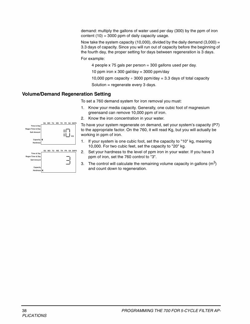
Volume/Demand Regeneration SettingTo set a 760 demand system for iron removal you must:
1. Know your media capacity. Generally, one cubic foot of magnesium greensand can remove 10,000 ppm of iron.
2. Know the iron concentration in your water.
To have your system regenerate on demand, set your system’s capacity (P7) to the appropriate factor. On the 760, it will read Kg, but you will actually be working in ppm of iron.
1. If your system is one cubic foot, set the capacity to "10" kg, meaning 10,000. For two cubic feet, set the capacity to "20" kg.
2. Set your hardness to the level of ppm iron in your water. If you have 3 ppm of iron, set the 760 control to "3".
3. The control will calculate the remaining volume capacity in gallons (m3) and count down to regeneration.
Time & Day
Regen Time & Day
Salt Amount
SU MO TU WE TH FR SA DAYS
Capacity
Hardness
KG
Time & Day
Regen Time & Day
Salt Amount
SU MO TU WE TH FR SA DAYS
Capacity
Hardness
PROGRAMMING THE 700 FOR 5-CYCLE FILTER APPLICATIONS 39Rev E
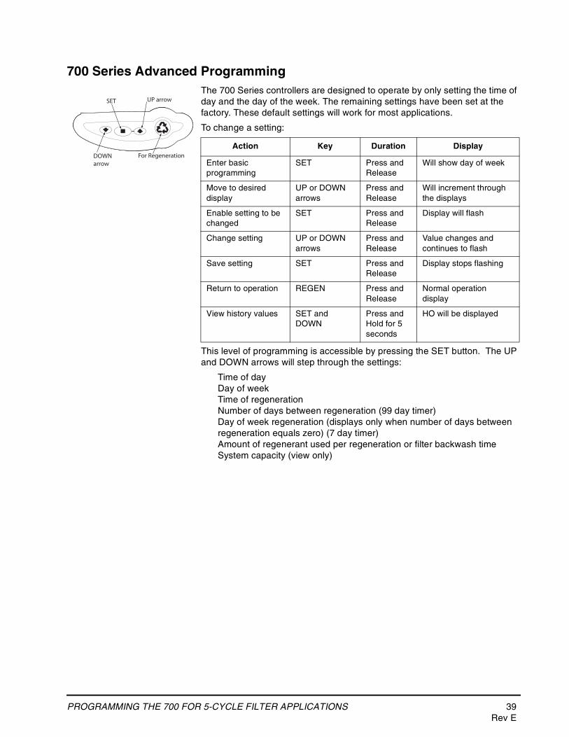
700 Series Advanced ProgrammingThe 700 Series controllers are designed to operate by only setting the time of day and the day of the week. The remaining settings have been set at the factory. These default settings will work for most applications.
To change a setting:
This level of programming is accessible by pressing the SET button. The UP and DOWN arrows will step through the settings:
Time of dayDay of weekTime of regenerationNumber of days between regeneration (99 day timer)Day of week regeneration (displays only when number of days between regeneration equals zero) (7 day timer)Amount of regenerant used per regeneration or filter backwash timeSystem capacity (view only)
Action Key Duration Display
Enter basic programming
SET Press and Release
Will show day of week
Move to desired display
UP or DOWN arrows
Press and Release
Will increment through the displays
Enable setting to be changed
SET Press and Release
Display will flash
Change setting UP or DOWN arrows
Press and Release
Value changes and continues to flash
Save setting SET Press and Release
Display stops flashing
Return to operation REGEN Press and Release
Normal operation display
View history values SET and DOWN
Press and Hold for 5 seconds
HO will be displayed
For Regeneration
SET UP arrow
DOWNarrow
40 PROGRAMMING THE 700 FOR 5-CYCLE FILTER AP-PLICATIONS
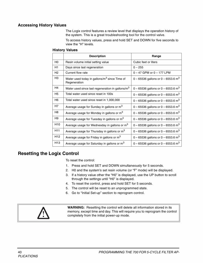
Accessing History ValuesThe Logix control features a review level that displays the operation history of the system. This is a great troubleshooting tool for the control valve.
To access history values, press and hold SET and DOWN for five seconds to view the "H" levels.
History Values
Resetting the Logix ControlTo reset the control:
1. Press and hold SET and DOWN simultaneously for 5 seconds.2. H0 and the system’s set resin volume (or “F” mode) will be displayed.3. If a history value other the “H0” is displayed, use the UP button to scroll
through the settings until “H0” is displayed.4. To reset the control, press and hold SET for 5 seconds.5. The control will be reset to an unprogrammed state.6. Go to “Initial Set-up” section to reprogram control.
Description Range
H0 Resin volume initial setting value Cubic feet or liters
H1 Days since last regeneration 0 – 255
H2 Current flow rate 0 – 47 GPM or 0 – 177 LPM
H3 Water used today in gallons/m3 since Time of Regeneration
0 – 65536 gallons or 0 – 6553.6 m3
H4 Water used since last regeneration in gallons/m3 0 – 65536 gallons or 0 – 6553.6 m3
H5 Total water used since reset in 100s 0 – 65536 gallons or 0 – 6553.6 m3
H6 Total water used since reset in 1,000,000 0 – 65536 gallons or 0 – 6553.6 m3
H7 Average usage for Sunday in gallons or m3 0 – 65536 gallons or 0 – 6553.6 m3
H8 Average usage for Monday in gallons or m3 0 – 65536 gallons or 0 – 6553.6 m3
H9 Average usage for Tuesday in gallons or m3 0 – 65536 gallons or 0 – 6553.6 m3
H10 Average usage for Wednesday in gallons or m3 0 – 65536 gallons or 0 – 6553.6 m3
H11 Average usage for Thursday in gallons or m3 0 – 65536 gallons or 0 – 6553.6 m3
H12 Average usage for Friday in gallons or m3 0 – 65536 gallons or 0 – 6553.6 m3
H13 Average usage for Saturday in gallons or m3 0 – 65536 gallons or 0 – 6553.6 m3
WARNING: Resetting the control will delete all information stored in its memory, except time and day. This will require you to reprogram the control completely from the initial power-up mode.
740/760 PROFESSIONAL PROGRAMMING 41Rev E
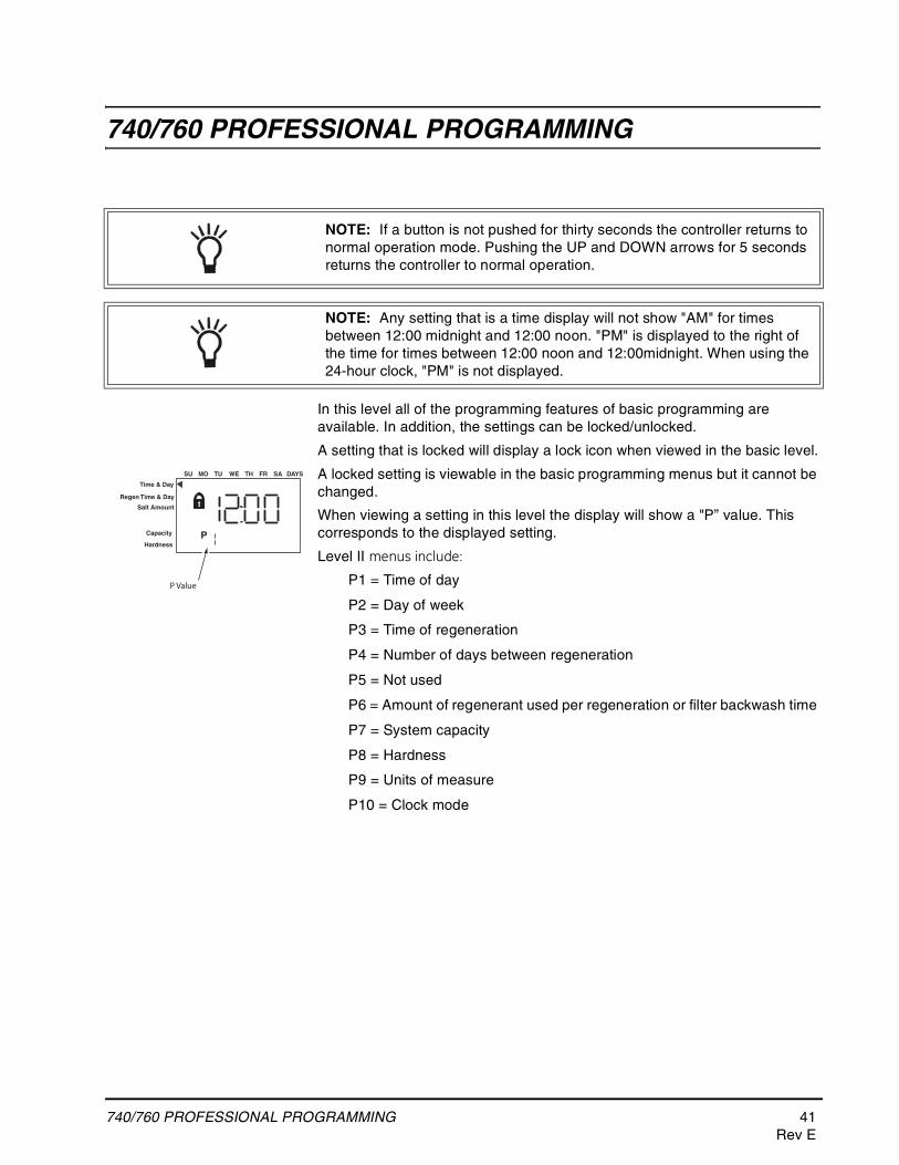
740/760 PROFESSIONAL PROGRAMMING
In this level all of the programming features of basic programming are available. In addition, the settings can be locked/unlocked.
A setting that is locked will display a lock icon when viewed in the basic level.
A locked setting is viewable in the basic programming menus but it cannot be changed.
When viewing a setting in this level the display will show a "P” value. This corresponds to the displayed setting.
Level II menus include:
P1 = Time of day
P2 = Day of week
P3 = Time of regeneration
P4 = Number of days between regeneration
P5 = Not used
P6 = Amount of regenerant used per regeneration or filter backwash time
P7 = System capacity
P8 = Hardness
P9 = Units of measure
P10 = Clock mode
NOTE: If a button is not pushed for thirty seconds the controller returns to normal operation mode. Pushing the UP and DOWN arrows for 5 seconds returns the controller to normal operation.
NOTE: Any setting that is a time display will not show "AM" for times between 12:00 midnight and 12:00 noon. "PM" is displayed to the right of the time for times between 12:00 noon and 12:00midnight. When using the 24-hour clock, "PM" is not displayed.
Time & Day
Regen Time & Day
Salt Amount
SU MO TU WE TH FR SA DAYS
PCapacity
Hardness
P Value
42 740/760 PROFESSIONAL PROGRAMMINGRev E
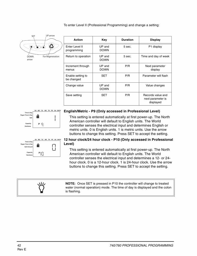
To enter Level II (Professional Programming) and change a setting:
English/Metric - P9 (Only accessed in Professional Level)
This setting is entered automatically at first power-up. The North American controller will default to English units. The World controller senses the electrical input and determines English or metric units. 0 is English units. 1 is metric units. Use the arrow buttons to change this setting. Press SET to accept the setting.
12 hour clock/24 hour clock - P10 (Only accessed in Professional Level)
This setting is entered automatically at first power-up. The North American controller will default to English units. The World controller senses the electrical input and determines a 12- or 24-hour clock. 0 is a 12-hour clock. 1 is 24-hour clock. Use the arrow buttons to change this setting. Press SET to accept the setting.
Action Key Duration Display
Enter Level II programming
UP and DOWN
5 sec. P1 display
Return to operation UP and DOWN
5 sec. Time and day of week
Increment through menus
UP and DOWN
P/R Next parameter display
Enable setting to be changed
SET P/R Parameter will flash
Change value UP and DOWN
P/R Value changes
Save setting SET P/R Records value and next parameter is
displayed
For Regeneration
SET UP arrow
DOWNarrow
Time & Day
Regen Time & Day
Salt
SU MO TU WE TH FR SA DAYS
PCapacity
Hardness
Time & Day
Regen Time & Day
Salt Amount
SU MO TU WE TH FR SA DAYS
PCapacity
Hardness
NOTE: Once SET is pressed in P10 the controller will change to treated water (normal operation) mode. The time of day is displayed and the colon is flashing.
VALVE SERVICE 43Rev E
VALVE SERVICE
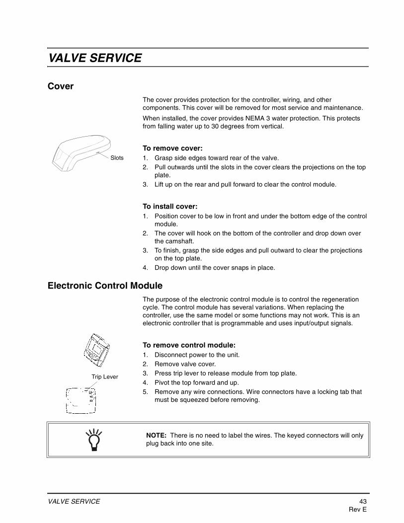
CoverThe cover provides protection for the controller, wiring, and other components. This cover will be removed for most service and maintenance.
When installed, the cover provides NEMA 3 water protection. This protects from falling water up to 30 degrees from vertical.
To remove cover:1. Grasp side edges toward rear of the valve.2. Pull outwards until the slots in the cover clears the projections on the top
plate.3. Lift up on the rear and pull forward to clear the control module.
To install cover:1. Position cover to be low in front and under the bottom edge of the control
module.2. The cover will hook on the bottom of the controller and drop down over
the camshaft.3. To finish, grasp the side edges and pull outward to clear the projections
on the top plate.4. Drop down until the cover snaps in place.
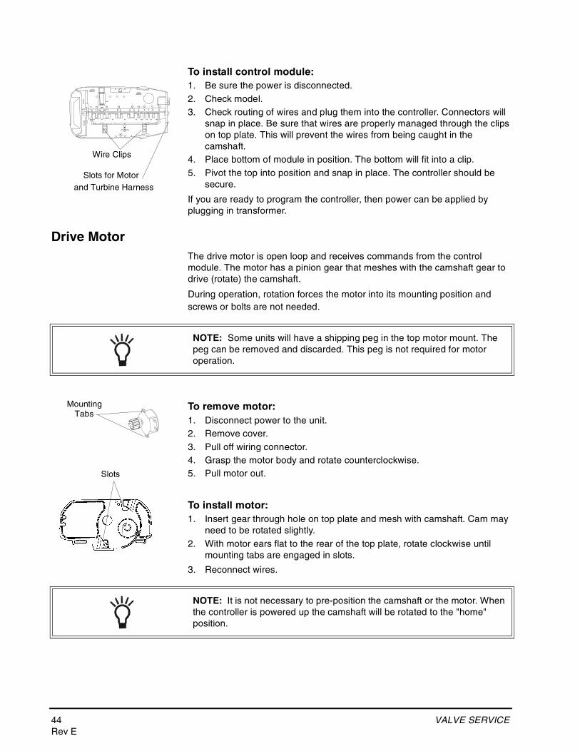
Electronic Control ModuleThe purpose of the electronic control module is to control the regeneration cycle. The control module has several variations. When replacing the controller, use the same model or some functions may not work. This is an electronic controller that is programmable and uses input/output signals.
To remove control module:1. Disconnect power to the unit.2. Remove valve cover.3. Press trip lever to release module from top plate.4. Pivot the top forward and up.5. Remove any wire connections. Wire connectors have a locking tab that
must be squeezed before removing.
Slots
Trip Lever
NOTE: There is no need to label the wires. The keyed connectors will only plug back into one site.
44 VALVE SERVICERev E
To install control module:1. Be sure the power is disconnected.2. Check model.3. Check routing of wires and plug them into the controller. Connectors will
snap in place. Be sure that wires are properly managed through the clips on top plate. This will prevent the wires from being caught in the camshaft.
4. Place bottom of module in position. The bottom will fit into a clip.5. Pivot the top into position and snap in place. The controller should be
secure.
If you are ready to program the controller, then power can be applied by plugging in transformer.
Drive MotorThe drive motor is open loop and receives commands from the control module. The motor has a pinion gear that meshes with the camshaft gear to drive (rotate) the camshaft.
During operation, rotation forces the motor into its mounting position and screws or bolts are not needed.
To remove motor:1. Disconnect power to the unit.2. Remove cover.3. Pull off wiring connector.4. Grasp the motor body and rotate counterclockwise.5. Pull motor out.
To install motor:1. Insert gear through hole on top plate and mesh with camshaft. Cam may
need to be rotated slightly.2. With motor ears flat to the rear of the top plate, rotate clockwise until
mounting tabs are engaged in slots.
3. Reconnect wires.
Wire Clips
Slots for Motor and Turbine Harness
NOTE: Some units will have a shipping peg in the top motor mount. The peg can be removed and discarded. This peg is not required for motor operation.
MountingTabs
Slots
NOTE: It is not necessary to pre-position the camshaft or the motor. When the controller is powered up the camshaft will be rotated to the "home" position.
VALVE SERVICE 45Rev E
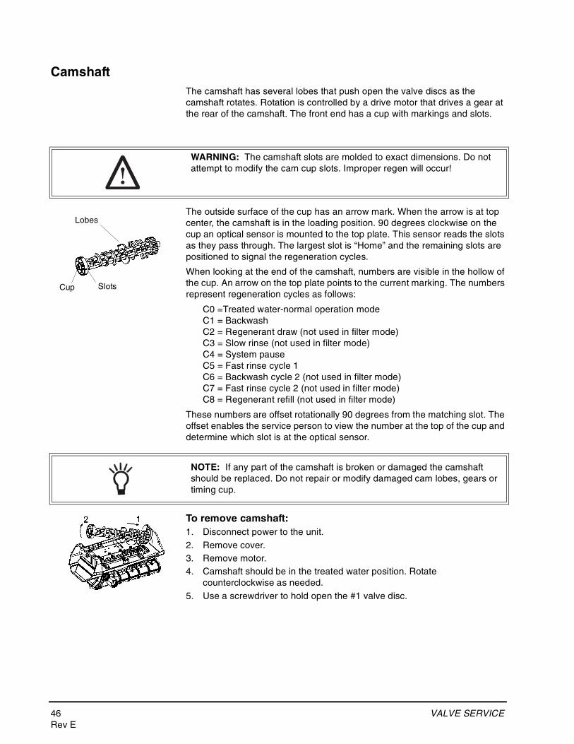
Optical SensorThe optical sensor is mounted to the top plate. The camshaft cup rotates through the sensor and the slots are detected. A signal is sent to the controller for each slot.
To remove optical sensor:1. Disconnect power to the unit.2. Remove cover.3. Remove controller.4. From the controller side, pinch the legs of the sensor holder in the top
plate.5. Pull the holder away from the mounting surface.6. Remove wires.
To install optical sensor:1. Attach wires. Wires should point away from camshaft.2. Place leading edge of sensor holder into opening.3. Pivot holder into place. Legs should enter slots and snap in place.
NOTE: Damaged sensors should be replaced. Sensors may be cleaned with compressed air or a soft brush.
Do not bend the legs on the optical sensor
WARNING: The optical sensor legs are fragile and may break. If the optical sensor legs break or crack, we recommend replacement. A damaged sensor may result in improper regeneration.
46 VALVE SERVICERev E
CamshaftThe camshaft has several lobes that push open the valve discs as the camshaft rotates. Rotation is controlled by a drive motor that drives a gear at the rear of the camshaft. The front end has a cup with markings and slots.
The outside surface of the cup has an arrow mark. When the arrow is at top center, the camshaft is in the loading position. 90 degrees clockwise on the cup an optical sensor is mounted to the top plate. This sensor reads the slots as they pass through. The largest slot is “Home” and the remaining slots are positioned to signal the regeneration cycles.
When looking at the end of the camshaft, numbers are visible in the hollow of the cup. An arrow on the top plate points to the current marking. The numbers represent regeneration cycles as follows:
C0 =Treated water-normal operation modeC1 = BackwashC2 = Regenerant draw (not used in filter mode)C3 = Slow rinse (not used in filter mode)C4 = System pauseC5 = Fast rinse cycle 1C6 = Backwash cycle 2 (not used in filter mode)C7 = Fast rinse cycle 2 (not used in filter mode)C8 = Regenerant refill (not used in filter mode)
These numbers are offset rotationally 90 degrees from the matching slot. The offset enables the service person to view the number at the top of the cup and determine which slot is at the optical sensor.
To remove camshaft:1. Disconnect power to the unit.2. Remove cover.3. Remove motor.4. Camshaft should be in the treated water position. Rotate
counterclockwise as needed.5. Use a screwdriver to hold open the #1 valve disc.
WARNING: The camshaft slots are molded to exact dimensions. Do not attempt to modify the cam cup slots. Improper regen will occur!
Slots
Lobes
Cup
NOTE: If any part of the camshaft is broken or damaged the camshaft should be replaced. Do not repair or modify damaged cam lobes, gears or timing cup.
VALVE SERVICE 47Rev E
6. Move the camshaft backwards, away from the controller.7. Lift the loose front end up and out.
To install camshaft:1. Check that the optical sensor is in position.2. Position camshaft above the valve discs. The arrow on the cup should be
up.3. Slide the rear of the camshaft into place.4. Pivot the camshaft close to its final position.5. The camshaft will push on one or more valve discs. You will feel
resistance as you complete the installation.6. Move the camshaft down and into position. Force valve discs to move as
needed.7. Move the camshaft forward. Check that the optical sensor is in position.8. Install motor.
NOTE: When replacing/removing camshaft, make sure not to damage or mis-align the optical sensor. Hold the sensor in position while removing camshaft.
NOTE: The camshaft will position itself to C0 (treated water) when the controller is powered up.
48 VALVE SERVICERev E
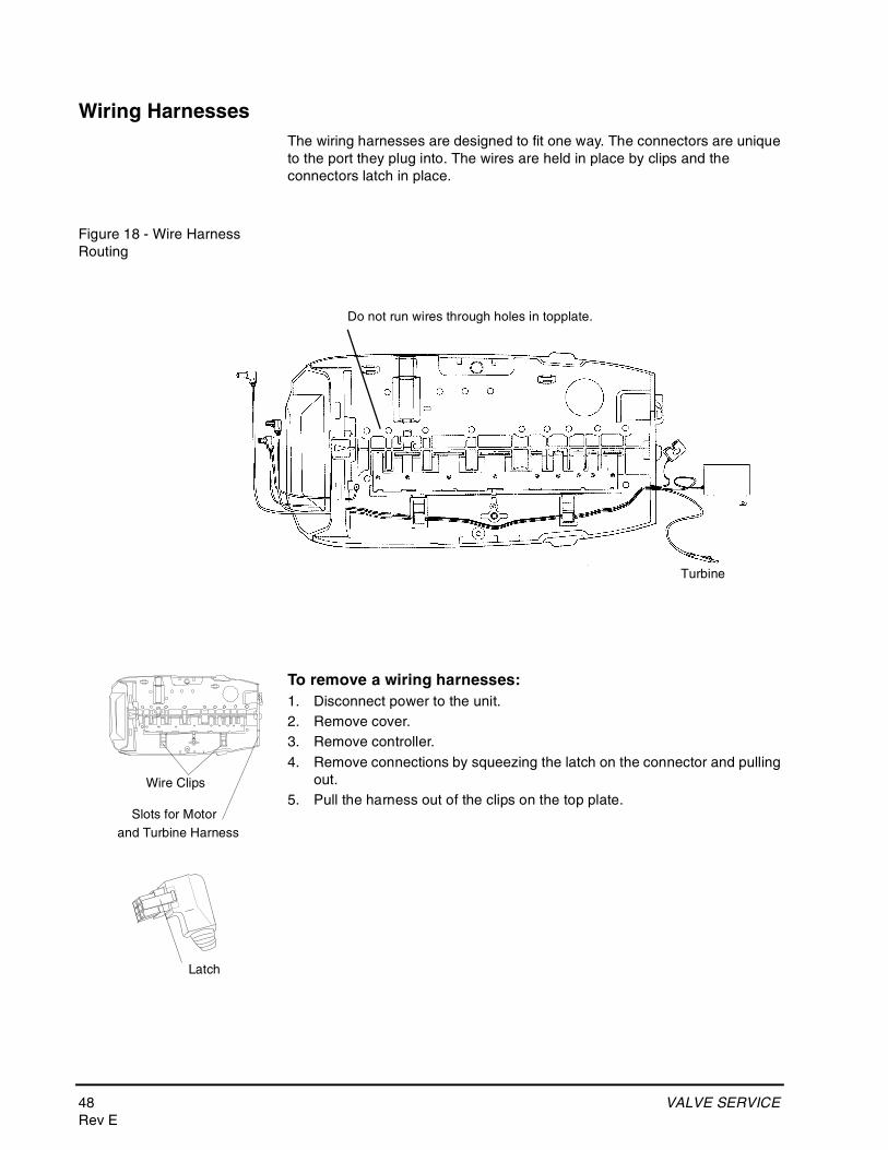
Wiring HarnessesThe wiring harnesses are designed to fit one way. The connectors are unique to the port they plug into. The wires are held in place by clips and the connectors latch in place.
Figure 18 - Wire Harness Routing
To remove a wiring harnesses:1. Disconnect power to the unit.2. Remove cover.3. Remove controller.4. Remove connections by squeezing the latch on the connector and pulling
out.5. Pull the harness out of the clips on the top plate.
Do not run wires through holes in topplate.
Turbine
Wire Clips
Slots for Motor and Turbine Harness
Latch
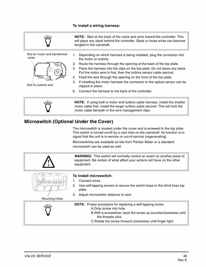
VALVE SERVICE 49Rev E
To install a wiring harness:
1. Depending on which harness is being installed, plug the connector into the motor or turbine.
2. Route the harness through the opening at the back of the top plate.3. Place the harness into the clips on the top plate. Do not leave any slack.
Put the motor wire in first, then the turbine sensor cable second.4. Feed the wire through the opening on the front of the top plate.5. If installing the motor harness the connector to the optical sensor can be
clipped in place.
6. Connect the harness to the back of the controller.
Microswitch (Optional Under the Cover)The microswitch is located under the cover and is screwed to the top plate. This switch is turned on/off by a cam lobe on the camshaft. Its function is to signal that the unit is in-service or out-of-service (regenerating).
Microswitches are available as kits from Pentair Water or a standard microswitch can be used as well.
To install microswitch:1. Connect wires.2. Use self-tapping screws to secure the switch base to the blind boss top
plate.
3. Adjust microswitch distance to cam.
NOTE: Start at the back of the valve and work toward the controller. This will place any slack behind the controller. Slack or loose wires can become tangled in the camshaft.
Slot for motor and transformer
Slot for turbine wire
wires
NOTE: If using both a motor and turbine cable harness, install the smaller motor cable first. Install the larger turbine cable second. This will lock the motor cable beneath in the wire management clips.
WARNING: This switch will normally control an event on another piece of equipment. Be certain of what effect your actions will have on the other equipment.
Mounting Holes
NOTE: Proper procedure for replacing a self-tapping screw:A.Drop screw into hole.B.With a screwdriver, back the screw up (counterclockwise) until
the threads click.C.Rotate the screw forward (clockwise) until finger tight.
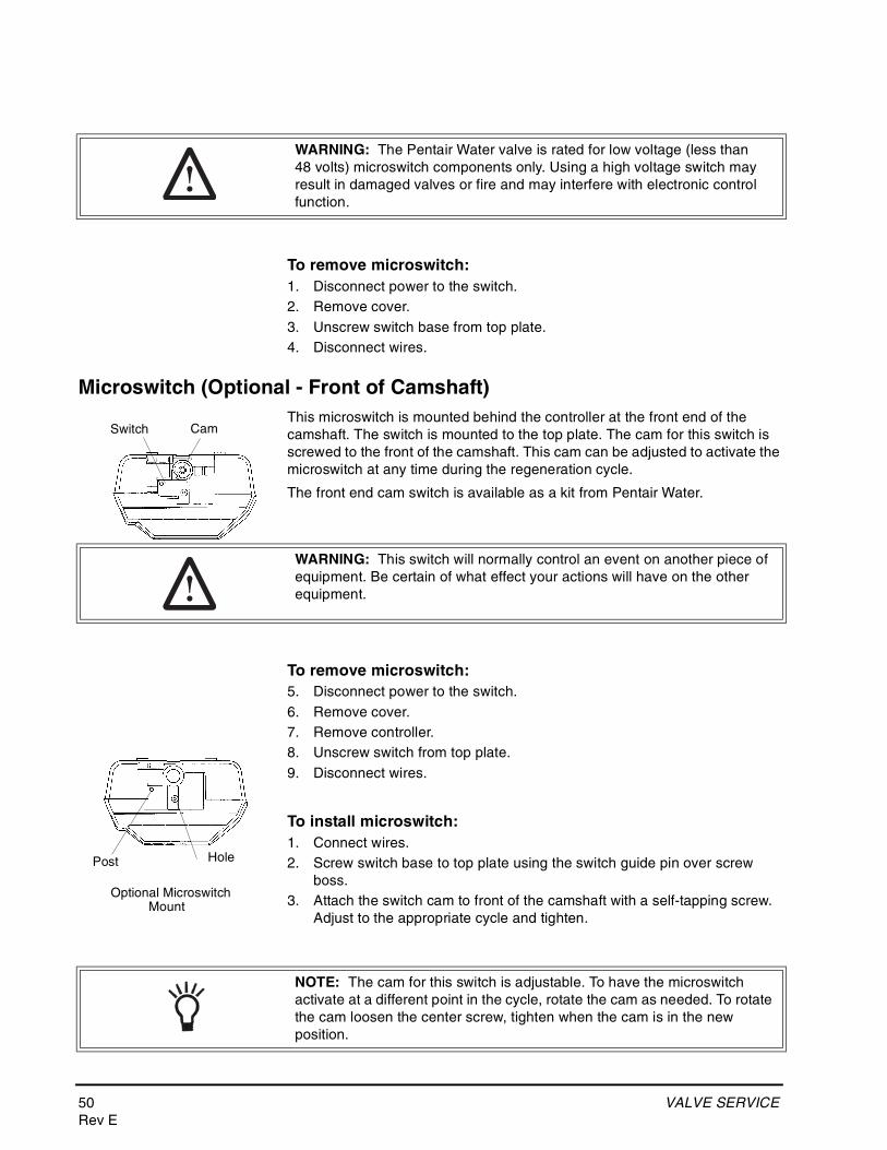
50 VALVE SERVICERev E
To remove microswitch:1. Disconnect power to the switch.2. Remove cover.3. Unscrew switch base from top plate.4. Disconnect wires.
Microswitch (Optional - Front of Camshaft)This microswitch is mounted behind the controller at the front end of the camshaft. The switch is mounted to the top plate. The cam for this switch is screwed to the front of the camshaft. This cam can be adjusted to activate the microswitch at any time during the regeneration cycle.
The front end cam switch is available as a kit from Pentair Water.
To remove microswitch:5. Disconnect power to the switch.6. Remove cover.7. Remove controller.8. Unscrew switch from top plate.9. Disconnect wires.
To install microswitch:1. Connect wires.2. Screw switch base to top plate using the switch guide pin over screw
boss.3. Attach the switch cam to front of the camshaft with a self-tapping screw.
Adjust to the appropriate cycle and tighten.
WARNING: The Pentair Water valve is rated for low voltage (less than 48 volts) microswitch components only. Using a high voltage switch may result in damaged valves or fire and may interfere with electronic control function.
CamSwitch
WARNING: This switch will normally control an event on another piece of equipment. Be certain of what effect your actions will have on the other equipment.
Optional MicroswitchMount
HolePost
NOTE: The cam for this switch is adjustable. To have the microswitch activate at a different point in the cycle, rotate the cam as needed. To rotate the cam loosen the center screw, tighten when the cam is in the new position.
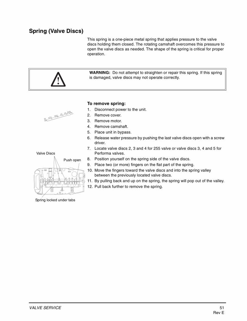
VALVE SERVICE 51Rev E
Spring (Valve Discs)This spring is a one-piece metal spring that applies pressure to the valve discs holding them closed. The rotating camshaft overcomes this pressure to open the valve discs as needed. The shape of the spring is critical for proper operation.
To remove spring:1. Disconnect power to the unit.2. Remove cover.3. Remove motor.4. Remove camshaft.5. Place unit in bypass.6. Release water pressure by pushing the last valve discs open with a screw
driver.7. Locate valve discs 2, 3 and 4 for 255 valve or valve discs 3, 4 and 5 for
Performa valves.8. Position yourself on the spring side of the valve discs.9. Place two (or more) fingers on the flat part of the spring.10. Move the fingers toward the valve discs and into the spring valley
between the previously located valve discs.11. By pulling back and up on the spring, the spring will pop out of the valley.12. Pull back further to remove the spring.
WARNING: Do not attempt to straighten or repair this spring. If this spring is damaged, valve discs may not operate correctly.
Push open
Spring locked under tabs
Valve Discs
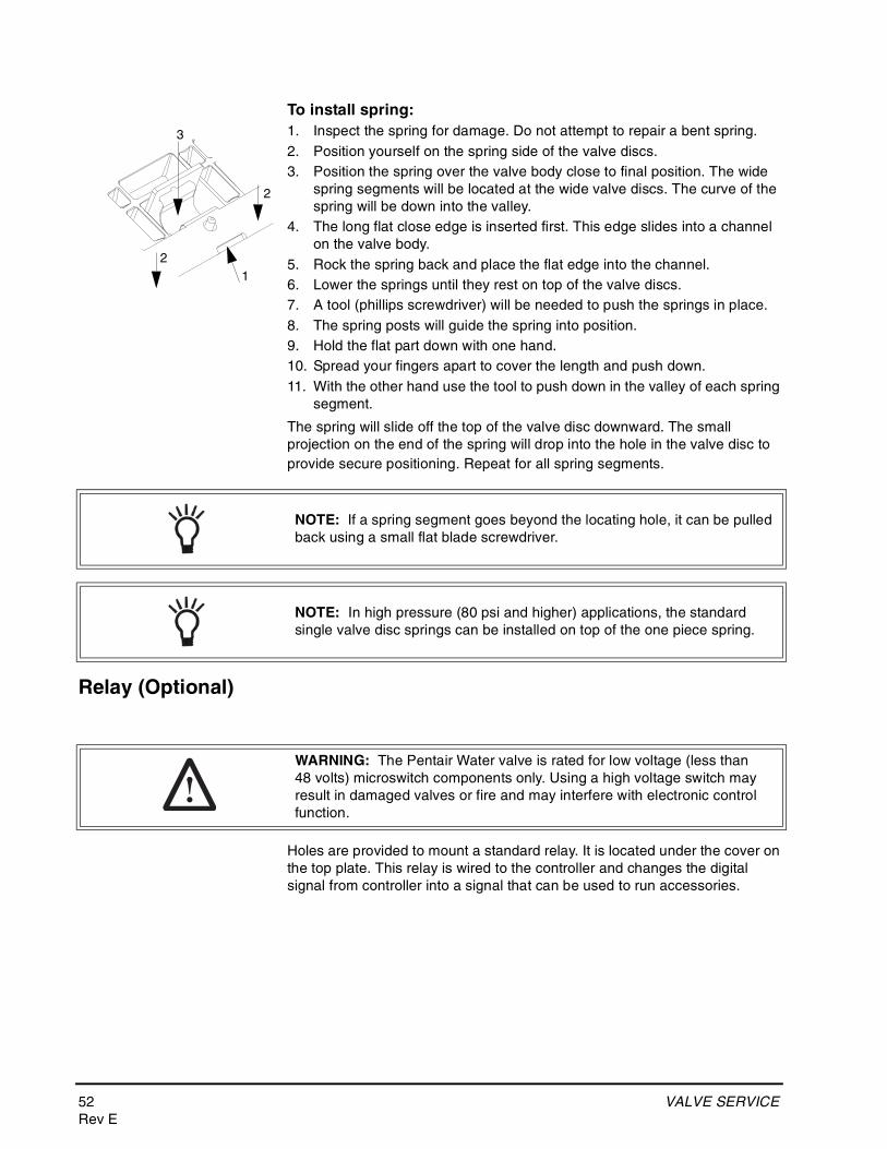
52 VALVE SERVICERev E
To install spring:1. Inspect the spring for damage. Do not attempt to repair a bent spring.2. Position yourself on the spring side of the valve discs.3. Position the spring over the valve body close to final position. The wide
spring segments will be located at the wide valve discs. The curve of the spring will be down into the valley.
4. The long flat close edge is inserted first. This edge slides into a channel on the valve body.
5. Rock the spring back and place the flat edge into the channel.6. Lower the springs until they rest on top of the valve discs.7. A tool (phillips screwdriver) will be needed to push the springs in place.8. The spring posts will guide the spring into position.9. Hold the flat part down with one hand.10. Spread your fingers apart to cover the length and push down.11. With the other hand use the tool to push down in the valley of each spring
segment.
The spring will slide off the top of the valve disc downward. The small projection on the end of the spring will drop into the hole in the valve disc to provide secure positioning. Repeat for all spring segments.
Relay (Optional)
Holes are provided to mount a standard relay. It is located under the cover on the top plate. This relay is wired to the controller and changes the digital signal from controller into a signal that can be used to run accessories.
12
3
2
NOTE: If a spring segment goes beyond the locating hole, it can be pulled back using a small flat blade screwdriver.
NOTE: In high pressure (80 psi and higher) applications, the standard single valve disc springs can be installed on top of the one piece spring.
WARNING: The Pentair Water valve is rated for low voltage (less than 48 volts) microswitch components only. Using a high voltage switch may result in damaged valves or fire and may interfere with electronic control function.
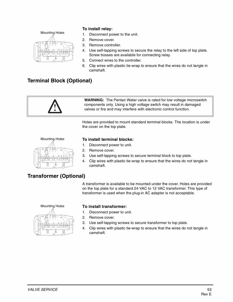
VALVE SERVICE 53Rev E
To install relay:1. Disconnect power to the unit.2. Remove cover.3. Remove controller.4. Use self-tapping screws to secure the relay to the left side of top plate.
Screw bosses are available for connecting relay.5. Connect wires to the controller.6. Clip wires with plastic tie-wrap to ensure that the wires do not tangle in
camshaft.
Terminal Block (Optional)
Holes are provided to mount standard terminal blocks. The location is under the cover on the top plate.
To install terminal blocks:1. Disconnect power to unit.2. Remove cover.3. Use self-tapping screws to secure terminal block to top plate.4. Clip wires with plastic tie-wrap to ensure that the wires do not tangle in
camshaft.
Transformer (Optional)A transformer is available to be mounted under the cover. Holes are provided on the top plate for a standard 24 VAC to 12 VAC transformer. This type of transformer is used when the plug-in AC adapter is not acceptable.
To install transformer:1. Disconnect power to unit.2. Remove cover.3. Use self-tapping screws to secure transformer to top plate.4. Clip wires with plastic tie-wrap to ensure that the wires do not tangle in
camshaft.
Mounting Holes
WARNING: The Pentair Water valve is rated for low voltage microswitch components only. Using a high voltage switch may result in damaged valves or fire and may interfere with electronic control function.
Mounting Holes
Mounting Holes
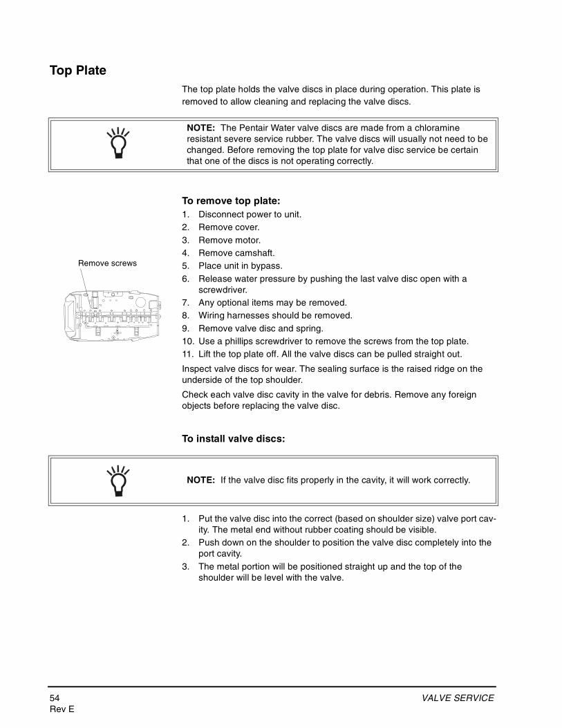
54 VALVE SERVICERev E
Top PlateThe top plate holds the valve discs in place during operation. This plate is removed to allow cleaning and replacing the valve discs.
To remove top plate:1. Disconnect power to unit.2. Remove cover.3. Remove motor.4. Remove camshaft.5. Place unit in bypass.6. Release water pressure by pushing the last valve disc open with a
screwdriver.7. Any optional items may be removed.8. Wiring harnesses should be removed.9. Remove valve disc and spring.10. Use a phillips screwdriver to remove the screws from the top plate.11. Lift the top plate off. All the valve discs can be pulled straight out.
Inspect valve discs for wear. The sealing surface is the raised ridge on the underside of the top shoulder.
Check each valve disc cavity in the valve for debris. Remove any foreign objects before replacing the valve disc.
To install valve discs:
1. Put the valve disc into the correct (based on shoulder size) valve port cav-ity. The metal end without rubber coating should be visible.
2. Push down on the shoulder to position the valve disc completely into the port cavity.
3. The metal portion will be positioned straight up and the top of the shoulder will be level with the valve.
NOTE: The Pentair Water valve discs are made from a chloramine resistant severe service rubber. The valve discs will usually not need to be changed. Before removing the top plate for valve disc service be certain that one of the discs is not operating correctly.
Remove screws
NOTE: If the valve disc fits properly in the cavity, it will work correctly.
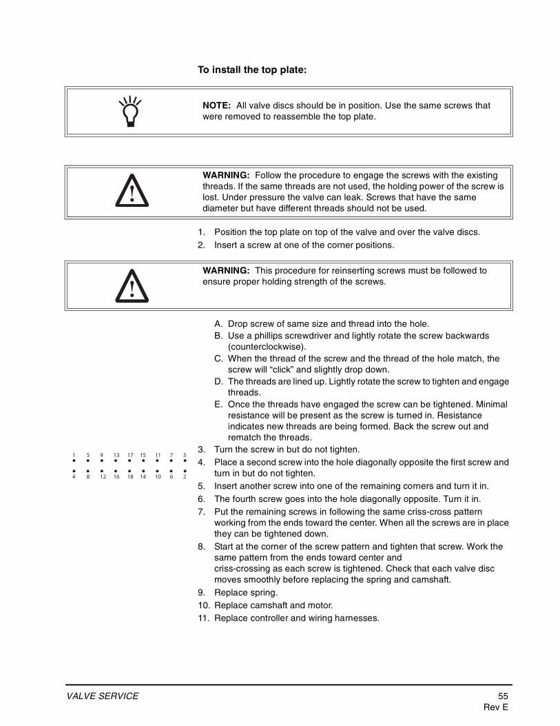
VALVE SERVICE 55Rev E
To install the top plate:
1. Position the top plate on top of the valve and over the valve discs.2. Insert a screw at one of the corner positions.
A. Drop screw of same size and thread into the hole.B. Use a phillips screwdriver and lightly rotate the screw backwards
(counterclockwise).C. When the thread of the screw and the thread of the hole match, the
screw will “click” and slightly drop down.D. The threads are lined up. Lightly rotate the screw to tighten and engage
threads.E. Once the threads have engaged the screw can be tightened. Minimal
resistance will be present as the screw is turned in. Resistance indicates new threads are being formed. Back the screw out and rematch the threads.
3. Turn the screw in but do not tighten.4. Place a second screw into the hole diagonally opposite the first screw and
turn in but do not tighten.5. Insert another screw into one of the remaining corners and turn it in.6. The fourth screw goes into the hole diagonally opposite. Turn it in.7. Put the remaining screws in following the same criss-cross pattern
working from the ends toward the center. When all the screws are in place they can be tightened down.
8. Start at the corner of the screw pattern and tighten that screw. Work the same pattern from the ends toward center and criss-crossing as each screw is tightened. Check that each valve disc moves smoothly before replacing the spring and camshaft.
9. Replace spring.10. Replace camshaft and motor.11. Replace controller and wiring harnesses.
NOTE: All valve discs should be in position. Use the same screws that were removed to reassemble the top plate.
WARNING: Follow the procedure to engage the screws with the existing threads. If the same threads are not used, the holding power of the screw is lost. Under pressure the valve can leak. Screws that have the same diameter but have different threads should not be used.
WARNING: This procedure for reinserting screws must be followed to ensure proper holding strength of the screws.
1 5 9 13 17 15 11 7 3
4 8 12 16 18 14 10 6 2
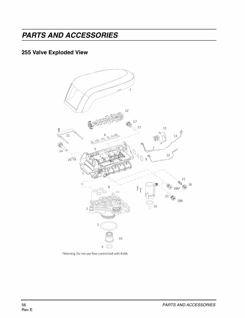
56 PARTS AND ACCESSORIESRev E
PARTS AND ACCESSORIES
255 Valve Exploded View
1
2
3
4
5
6
7
8
9
11
12
14
15
16
10
18A*
20
13
17
19
13
18B
*Warning: Do not use flow control ball with #18A.
21
21
22
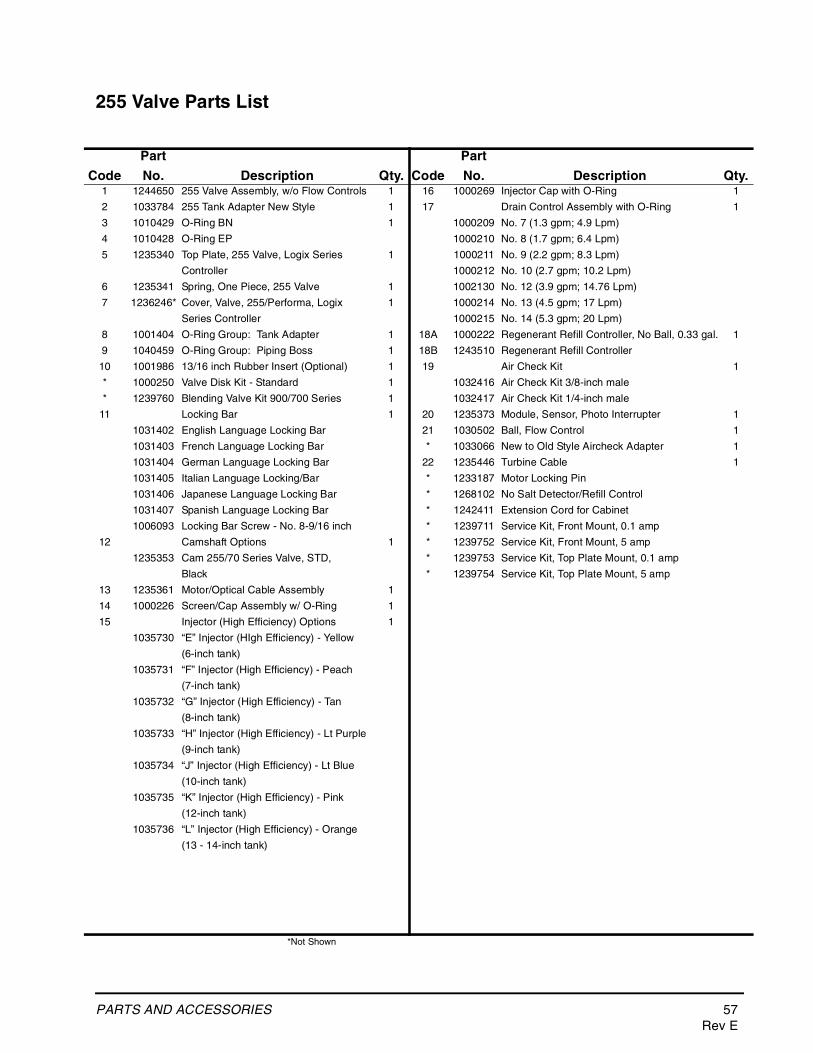
PARTS AND ACCESSORIES 57Rev E
255 Valve Parts List
*Not Shown
Code
Part
No. Description Qty. Code
Part
No. Description Qty.1 1244650 255 Valve Assembly, w/o Flow Controls 1 16 1000269 Injector Cap with O-Ring 1
2 1033784 255 Tank Adapter New Style 1 17 Drain Control Assembly with O-Ring 1
3 1010429 O-Ring BN 1 1000209 No. 7 (1.3 gpm; 4.9 Lpm)
4 1010428 O-Ring EP 1000210 No. 8 (1.7 gpm; 6.4 Lpm)
5 1235340 Top Plate, 255 Valve, Logix Series 1 1000211 No. 9 (2.2 gpm; 8.3 Lpm)
Controller 1000212 No. 10 (2.7 gpm; 10.2 Lpm)
6 1235341 Spring, One Piece, 255 Valve 1 1002130 No. 12 (3.9 gpm; 14.76 Lpm)
7 1236246* Cover, Valve, 255/Performa, Logix 1 1000214 No. 13 (4.5 gpm; 17 Lpm)
Series Controller 1000215 No. 14 (5.3 gpm; 20 Lpm)
8 1001404 O-Ring Group: Tank Adapter 1 18A 1000222 Regenerant Refill Controller, No Ball, 0.33 gal. 1
9 1040459 O-Ring Group: Piping Boss 1 18B 1243510 Regenerant Refill Controller
10 1001986 13/16 inch Rubber Insert (Optional) 1 19 Air Check Kit 1
* 1000250 Valve Disk Kit - Standard 1 1032416 Air Check Kit 3/8-inch male
* 1239760 Blending Valve Kit 900/700 Series 1 1032417 Air Check Kit 1/4-inch male
11 Locking Bar 1 20 1235373 Module, Sensor, Photo Interrupter 1
1031402 English Language Locking Bar 21 1030502 Ball, Flow Control 1
1031403 French Language Locking Bar * 1033066 New to Old Style Aircheck Adapter 1
1031404 German Language Locking Bar 22 1235446 Turbine Cable 1
1031405 Italian Language Locking/Bar * 1233187 Motor Locking Pin
1031406 Japanese Language Locking Bar * 1268102 No Salt Detector/Refill Control
1031407 Spanish Language Locking Bar * 1242411 Extension Cord for Cabinet
1006093 Locking Bar Screw - No. 8-9/16 inch * 1239711 Service Kit, Front Mount, 0.1 amp
12 Camshaft Options 1 * 1239752 Service Kit, Front Mount, 5 amp
1235353 Cam 255/70 Series Valve, STD, * 1239753 Service Kit, Top Plate Mount, 0.1 amp
Black * 1239754 Service Kit, Top Plate Mount, 5 amp
13 1235361 Motor/Optical Cable Assembly 1
14 1000226 Screen/Cap Assembly w/ O-Ring 1
15 Injector (High Efficiency) Options 1
1035730 “E” Injector (HIgh Efficiency) - Yellow
(6-inch tank)
1035731 “F” Injector (High Efficiency) - Peach
(7-inch tank)
1035732 “G” Injector (High Efficiency) - Tan
(8-inch tank)
1035733 “H” Injector (High Efficiency) - Lt Purple
(9-inch tank)
1035734 “J” Injector (High Efficiency) - Lt Blue
(10-inch tank)
1035735 “K” Injector (High Efficiency) - Pink
(12-inch tank)
1035736 “L” Injector (High Efficiency) - Orange
(13 - 14-inch tank)
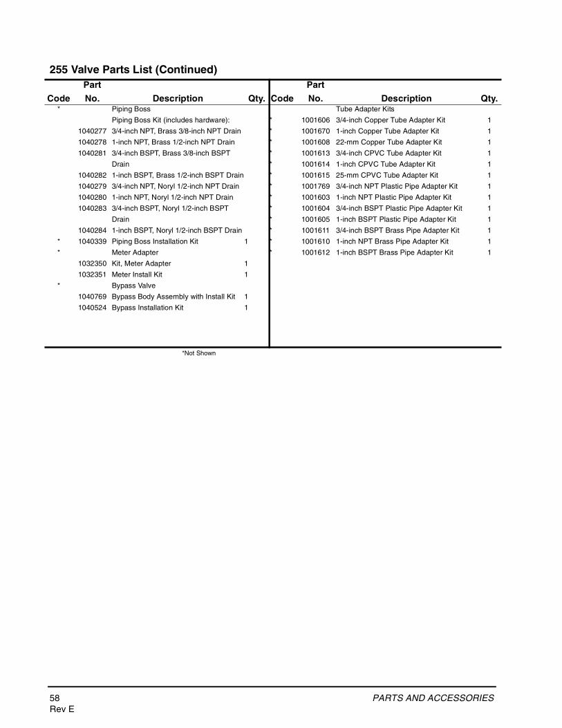
58 PARTS AND ACCESSORIESRev E
255 Valve Parts List (Continued)
*Not Shown
Code
Part
No. Description Qty. Code
Part
No. Description Qty.* Piping Boss Tube Adapter Kits
Piping Boss Kit (includes hardware): * 1001606 3/4-inch Copper Tube Adapter Kit 1
1040277 3/4-inch NPT, Brass 3/8-inch NPT Drain * 1001670 1-inch Copper Tube Adapter Kit 1
1040278 1-inch NPT, Brass 1/2-inch NPT Drain * 1001608 22-mm Copper Tube Adapter Kit 1
1040281 3/4-inch BSPT, Brass 3/8-inch BSPT * 1001613 3/4-inch CPVC Tube Adapter Kit 1
Drain * 1001614 1-inch CPVC Tube Adapter Kit 1
1040282 1-inch BSPT, Brass 1/2-inch BSPT Drain * 1001615 25-mm CPVC Tube Adapter Kit 1
1040279 3/4-inch NPT, Noryl 1/2-inch NPT Drain * 1001769 3/4-inch NPT Plastic Pipe Adapter Kit 1
1040280 1-inch NPT, Noryl 1/2-inch NPT Drain * 1001603 1-inch NPT Plastic Pipe Adapter Kit 1
1040283 3/4-inch BSPT, Noryl 1/2-inch BSPT * 1001604 3/4-inch BSPT Plastic Pipe Adapter Kit 1
Drain * 1001605 1-inch BSPT Plastic Pipe Adapter Kit 1
1040284 1-inch BSPT, Noryl 1/2-inch BSPT Drain * 1001611 3/4-inch BSPT Brass Pipe Adapter Kit 1
* 1040339 Piping Boss Installation Kit 1 * 1001610 1-inch NPT Brass Pipe Adapter Kit 1
* Meter Adapter * 1001612 1-inch BSPT Brass Pipe Adapter Kit 1
1032350 Kit, Meter Adapter 1
1032351 Meter Install Kit 1
* Bypass Valve
1040769 Bypass Body Assembly with Install Kit 1
1040524 Bypass Installation Kit 1
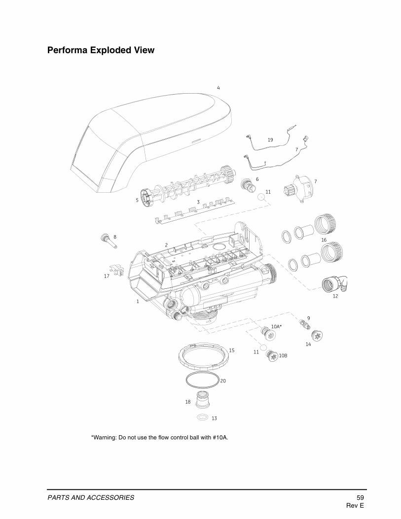
PARTS AND ACCESSORIES 59Rev E
Performa Exploded View
2
1
3
4
5
6
7
8
9
10A*
11
12
13
14
16
17
7
15
18
10B11
*Warning: Do not use the flow control ball with #10A.
19
20
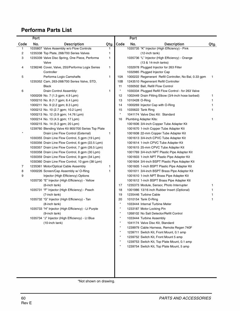
60 PARTS AND ACCESSORIESRev E
Performa Parts List
*Not shown on drawing.
CodePartNo. Description Qty. Code
PartNo. Description Qty.
1 1035807 Valve Assembly w/o Flow Controls 1 1035735 “K” Injector (High Efficiency) - Pink
2 1235338 Top Plate, 268/700 Series Valves 1 (12-inch tank)
3 1235339 Valve Disc Spring, One Piece, Performa 1 1035736 “L” Injector (High Efficiency) - Orange
Valve (13 & 14-inch tanks)
4 1236246 Cover, Valve, 255/Performa Logix Series 1 1032978 Plugged Injector for 263 Filter
Controller 1032985 Plugged Injector Cap
5 Performa Logix Camshafts 1 10A 1000222 Regenerant Refill Controller, No Bal, 0.33 gpm 1
1235352 Cam, 263-268/700 Series Valve, STD, 10B 1243510 Regenerant Refill Controller
Black 11 1030502 Ball, Refill Flow Control
6 Drain Control Assembly: 1 * 1030334 Plugged Refill Flow Control - for 263 Valve
1000209 No. 7 (1.3 gpm; 4.9 Lpm) 12 1002449 Drain Fitting Elbow (3/4-inch hose barbed) 1
1000210 No. 8 (1.7 gpm; 6.4 Lpm) 13 1010428 O-Ring 1
1000211 No. 9 (2.2 gpm; 8.3 Lpm) 14 1000269 Injector Cap with O-Ring 1
1000212 No. 10 (2.7 gpm; 10.2 Lpm) 15 1035622 Tank Ring 1
1000213 No. 12 (3.9 gpm; 14.76 Lpm) * 1041174 Valve Disc Kit: Standard
1000214 No. 13 (4.5 gpm; 17 Lpm) 16 Plumbing Adapter Kits: 1
1000215 No. 14 (5.3 gpm; 20 Lpm) 1001606 3/4-inch Copper Tube Adapter Kit
1239760 Blending Valve Kit 900/700 Series Top Plate 1001670 1-inch Copper Tube Adapter Kit
* Drain Line Flow Control (External) 1 1001608 22-mm Copper Tube Adapter Kit
1030355 Drain Line Flow Control, 5 gpm (19 Lpm) 1001613 3/4-inch CPVC Tube Adapter Kit
1030356 Drain Line Flow Control, 6 gpm (22.5 Lpm) 1001614 1-inch CPVC Tube Adapter Kit
1030357 Drain Line Flow Control, 7 gpm (26.5 Lpm) 1001615 25-mm CPVC Tube Adapter Kit
1030358 Drain Line Flow Control, 8 gpm (30 Lpm) 1001769 3/4-inch NPT Plastic Pipe Adapter Kit
1030359 Drain Line Flow Control, 9 gpm (34 Lpm) 1001603 1-inch NPT Plastic Pipe Adapter Kit
1030360 Drain Line Flow Control, 10 gpm (38 Lpm) 1001604 3/4-inch BSPT Plastic Pipe Adapter Kit
7 1235361 Motor/Optical Cable Assembly 1 1001605 1-inch BSPT Plastic Pipe Adapter Kit
8 1000226 Screen/Cap Assembly w/ O-Ring 1 1001611 3/4-inch BSPT Brass Pipe Adapter Kit
9 Injector (High Efficiency) Options 1001610 1-inch NPT Brass Pipe Adapter Kit
1035730 “E” Injector (HIgh Efficiency) - Yellow 1001612 1-inch BSPT Brass Pipe Adapter Kit
(6-inch tank) 17 1235373 Module, Sensor, Photo Interrupter 1
1035731 “F” Injector (High Efficiency) - Peach 18 1001986 13/16 inch Rubber Insert (Optional) 1
(7-inch tank) 19 1235446 Turbine Cable 1
1035732 “G” Injector (High Efficiency) - Tan 20 1010154 Tank O-Ring 1
(8-inch tank) * 1033444 Internal Turbine Meter
1035733 “H” Injector (High Efficiency) - Lt Purple * 1233187 Motor Locking Pin
(9-inch tank) * 1268102 No Salt Detector/Refill Control
1035734 “J” Injector (High Efficiency) - Lt Blue * 1033444 Turbine Assembly
(10-inch tank) * 1041174 Valve Disc Kit, Standard
* 1239979 Cable Harness, Remote Regen 740F
* 1239711 Switch Kit, Front Mount, 0.1 amp
* 1239752 Switch Kit, Front Mount 5 amp
* 1239753 Switch Kit, Top Plate Mount, 0.1 amp
* 1239754 Switch Kit, Top Plate Mount, 5 amp
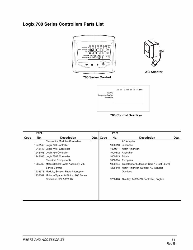
PARTS AND ACCESSORIES 61Rev E
Logix 700 Series Controllers Parts List
700 Series Control
Time & Day
Regen Time & Day
Salt
SU MO TU WE TH FR SA DAYS
LBS
PMMIN
KG
x100x2
PHC
Capacity
Hardness
AC Adapter
Time/Day
Su Mo Tu We Th Fr Sa DAYS
Regeneration Time/DaySalt Amount
700 Control Overlays
CodePartNo. Description Qty. Code
PartNo. Description Qty.
Electronics Modules/Controllers 1 AC Adapter
1242146 Logix 740 Controller 1000810 Japanese
1242148 Logix 740F Controller 1000811 North American
1242163 Logix 760 Controller 1000812 Australian
1242166 Logix 760F Controller 1000813 British
Electrical Components 1000814 European
1235269 Motor/Optical Cable Assembly, 700 1030234 Transformer Extension Cord 15 foot (4.5m)
Series Control 1235448 North American Outdoor AC Adapter
1235373 Module, Sensor, Photo Interrupter Overlays
1235361 Motor w/Spacer & Pinion, 700 Series
Controller 12V, 50/60 Hz 1238476 Overlay, 740/742C Controller, English
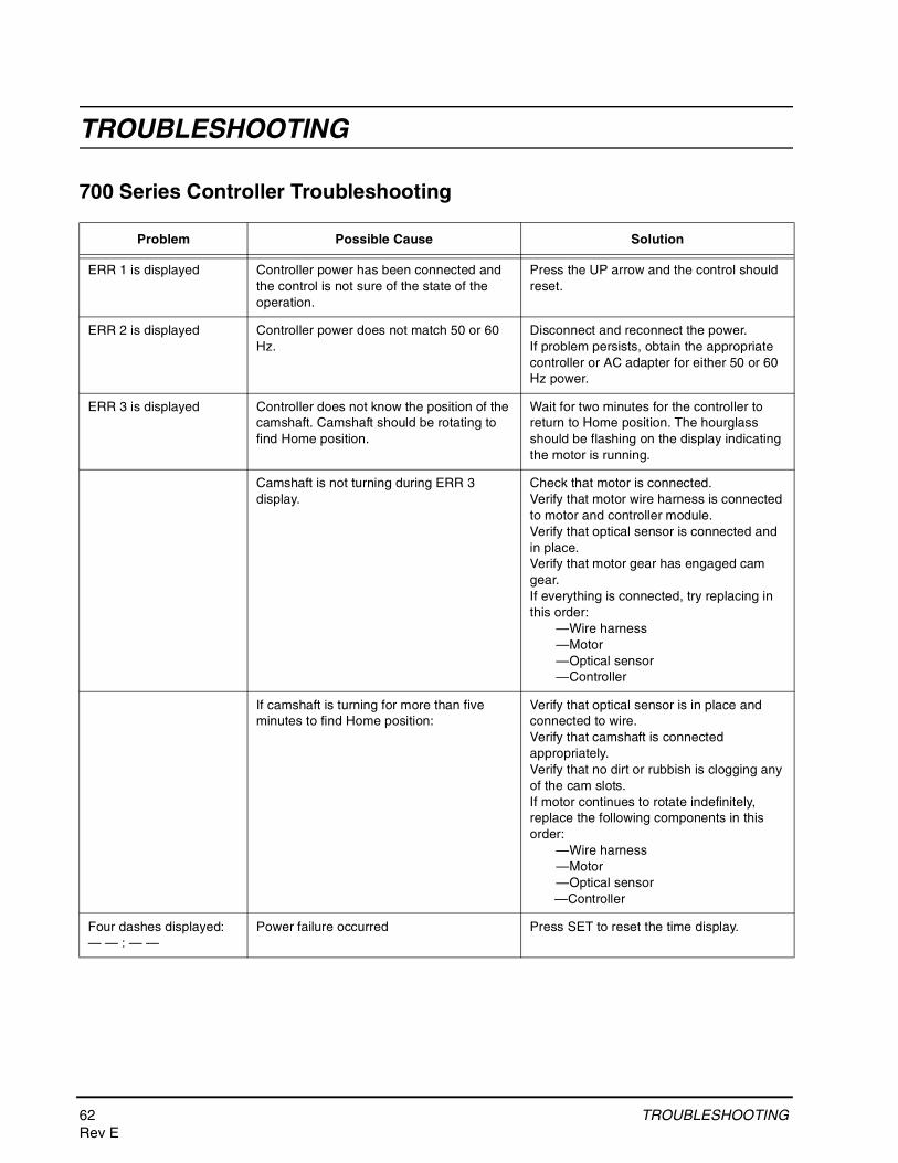
62 TROUBLESHOOTINGRev E
TROUBLESHOOTING
700 Series Controller Troubleshooting
Problem Possible Cause Solution
ERR 1 is displayed Controller power has been connected and the control is not sure of the state of the operation.
Press the UP arrow and the control should reset.
ERR 2 is displayed Controller power does not match 50 or 60 Hz.
Disconnect and reconnect the power.If problem persists, obtain the appropriate controller or AC adapter for either 50 or 60 Hz power.
ERR 3 is displayed Controller does not know the position of the camshaft. Camshaft should be rotating to find Home position.
Wait for two minutes for the controller to return to Home position. The hourglass should be flashing on the display indicating the motor is running.
Camshaft is not turning during ERR 3 display.
Check that motor is connected.Verify that motor wire harness is connected to motor and controller module.Verify that optical sensor is connected and in place. Verify that motor gear has engaged cam gear.If everything is connected, try replacing in this order:
—Wire harness—Motor—Optical sensor—Controller
If camshaft is turning for more than five minutes to find Home position:
Verify that optical sensor is in place and connected to wire.Verify that camshaft is connected appropriately.Verify that no dirt or rubbish is clogging any of the cam slots.If motor continues to rotate indefinitely, replace the following components in this order:
—Wire harness—Motor—Optical sensor—Controller
Four dashes displayed:— — : — —
Power failure occurred Press SET to reset the time display.
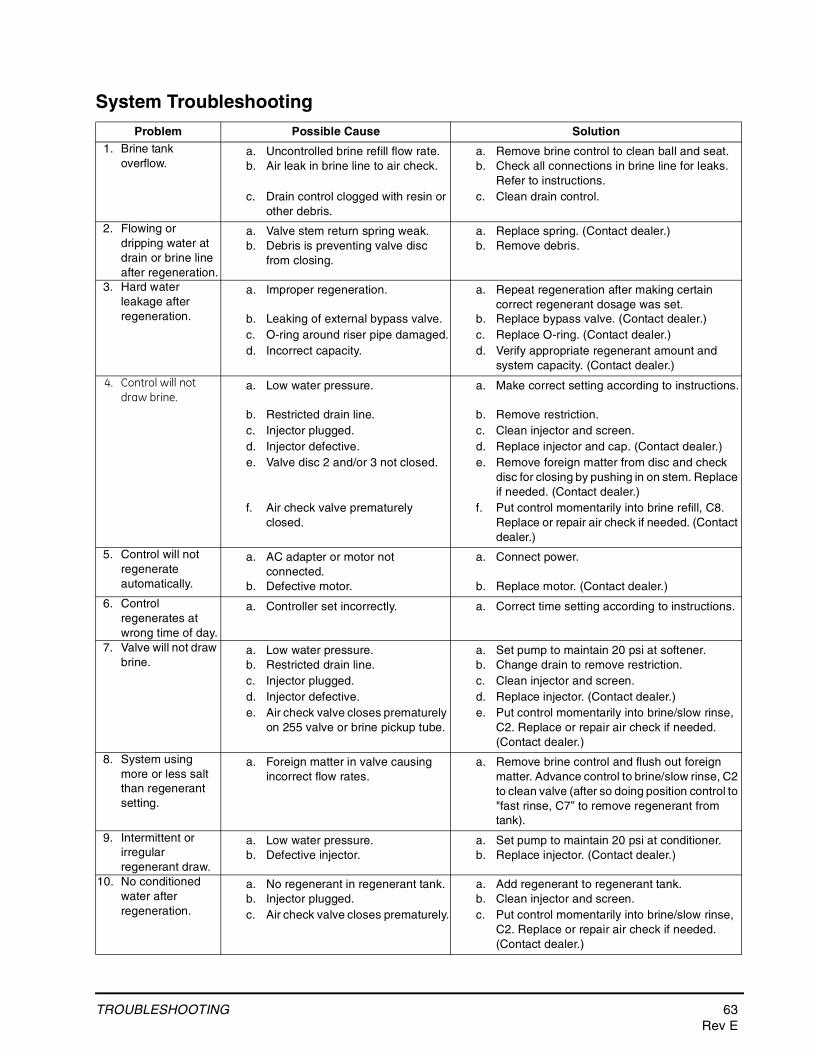
TROUBLESHOOTING 63Rev E
System TroubleshootingProblem Possible Cause Solution
1. Brine tank overflow.
a. Uncontrolled brine refill flow rate.b. Air leak in brine line to air check.
c. Drain control clogged with resin or other debris.
a. Remove brine control to clean ball and seat.b. Check all connections in brine line for leaks.
Refer to instructions.c. Clean drain control.
2. Flowing or dripping water at drain or brine line after regeneration.
a. Valve stem return spring weak.b. Debris is preventing valve disc
from closing.
a. Replace spring. (Contact dealer.)b. Remove debris.
3. Hard water leakage after regeneration.
a. Improper regeneration.
b. Leaking of external bypass valve.c. O-ring around riser pipe damaged.d. Incorrect capacity.
a. Repeat regeneration after making certain correct regenerant dosage was set.
b. Replace bypass valve. (Contact dealer.)c. Replace O-ring. (Contact dealer.)d. Verify appropriate regenerant amount and
system capacity. (Contact dealer.)
4. Control will not draw brine.
a. Low water pressure.
b. Restricted drain line.c. Injector plugged.d. Injector defective.e. Valve disc 2 and/or 3 not closed.
f. Air check valve prematurely closed.
a. Make correct setting according to instructions.
b. Remove restriction.c. Clean injector and screen.d. Replace injector and cap. (Contact dealer.)e. Remove foreign matter from disc and check
disc for closing by pushing in on stem. Replace if needed. (Contact dealer.)
f. Put control momentarily into brine refill, C8. Replace or repair air check if needed. (Contact dealer.)
5. Control will not regenerate automatically.
a. AC adapter or motor not connected.
b. Defective motor.
a. Connect power.
b. Replace motor. (Contact dealer.)
6. Control regenerates at wrong time of day.
a. Controller set incorrectly. a. Correct time setting according to instructions.
7. Valve will not draw brine.
a. Low water pressure.b. Restricted drain line.c. Injector plugged.d. Injector defective.e. Air check valve closes prematurely
on 255 valve or brine pickup tube.
a. Set pump to maintain 20 psi at softener.b. Change drain to remove restriction.c. Clean injector and screen.d. Replace injector. (Contact dealer.)e. Put control momentarily into brine/slow rinse,
C2. Replace or repair air check if needed. (Contact dealer.)
8. System using more or less salt than regenerant setting.
a. Foreign matter in valve causing incorrect flow rates.
a. Remove brine control and flush out foreign matter. Advance control to brine/slow rinse, C2 to clean valve (after so doing position control to "fast rinse, C7” to remove regenerant from tank).
9. Intermittent or irregular regenerant draw.
a. Low water pressure.b. Defective injector.
a. Set pump to maintain 20 psi at conditioner.b. Replace injector. (Contact dealer.)
10. No conditioned water after regeneration.
a. No regenerant in regenerant tank.b. Injector plugged.c. Air check valve closes prematurely.
a. Add regenerant to regenerant tank.b. Clean injector and screen.c. Put control momentarily into brine/slow rinse,
C2. Replace or repair air check if needed. (Contact dealer.)
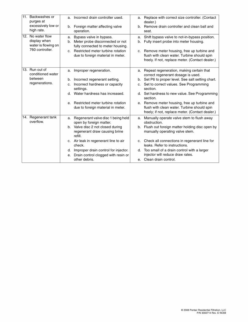
© 2008 Pentair Residential Filtration, LLCP/N 3003714 Rev. E NO08
11. Backwashes or purges at excessively low or high rate.
a. Incorrect drain controller used.
b. Foreign matter affecting valve operation.
a. Replace with correct size controller. (Contact dealer.)
b. Remove drain controller and clean ball and seat.
12. No water flow display when water is flowing on 760 controller.
a. Bypass valve in bypass.b. Meter probe disconnected or not
fully connected to meter housing.c. Restricted meter turbine rotation
due to foreign material in meter.
a. Shift bypass valve to not-in-bypass position.b. Fully insert probe into meter housing.
c. Remove meter housing, free up turbine and flush with clean water. Turbine should spin freely. If not, replace meter. (Contact dealer.)
13. Run out of conditioned water between regenerations.
a. Improper regeneration.
b. Incorrect regenerant setting.c. Incorrect hardness or capacity
settings.d. Water hardness has increased.
e. Restricted meter turbine rotation due to foreign material in meter.
a. Repeat regeneration, making certain that correct regenerant dosage is used.
b. Set P6 to proper level. See salt setting chart. c. Set to correct values. See Programming
section.d. Set hardness to new value. See Programming
section.e. Remove meter housing, free up turbine and
flush with clean water. Turbine should spin freely; if not, replace meter. (Contact dealer.)
14. Regenerant tank overflow.
a. Regenerant valve disc 1 being held open by foreign matter.
b. Valve disc 2 not closed during regenerant draw causing brine refill.
c. Air leak in regenerant line to air check.
d. Improper drain control for injector.e. Drain control clogged with resin or
other debris.
a. Manually operate valve stem to flush away obstruction.
b. Flush out foreign matter holding disc open by manually operating valve stem.
c. Check all connections in regenerant line for leaks. Refer to instructions.
d. Too small of a drain control with a larger injector will reduce draw rates.
e. Clean drain control.