Embed Size (px)
Citation preview
Logix 500siDigital Positioner
2
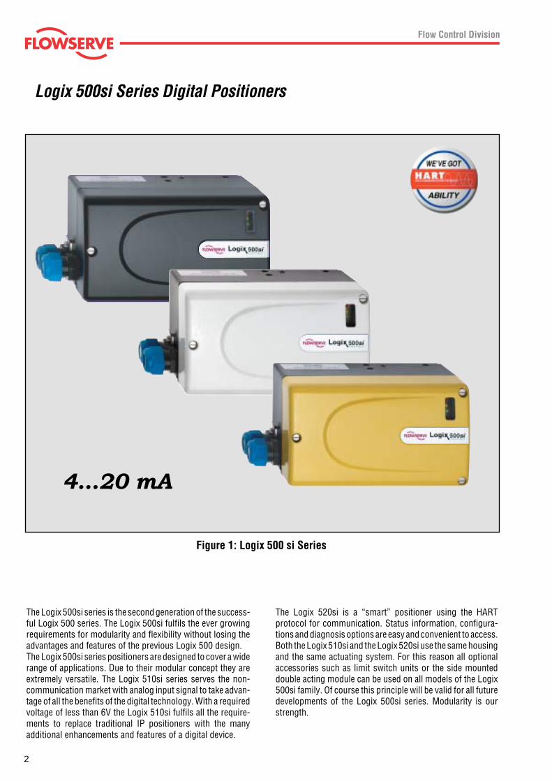
Figure 1: Logix 500 si Series
4...20 mA
Logix 500si Series Digital Positioners
The Logix 500si series is the second generation of the success-ful Logix 500 series. The Logix 500si fulfils the ever growingrequirements for modularity and flexibility without losing theadvantages and features of the previous Logix 500 design.The Logix 500si series positioners are designed to cover a widerange of applications. Due to their modular concept they areextremely versatile. The Logix 510si series serves the non-communication market with analog input signal to take advan-tage of all the benefits of the digital technology. With a requiredvoltage of less than 6V the Logix 510si fulfils all the require-ments to replace traditional IP positioners with the manyadditional enhancements and features of a digital device.
The Logix 520si is a “smart” positioner using the HARTprotocol for communication. Status information, configura-tions and diagnosis options are easy and convenient to access.Both the Logix 510si and the Logix 520si use the same housingand the same actuating system. For this reason all optionalaccessories such as limit switch units or the side mounteddouble acting module can be used on all models of the Logix500si family. Of course this principle will be valid for all futuredevelopments of the Logix 500si series. Modularity is ourstrength.
3
Features and Advantages
Features Advantages
Easy commissioning Commissioning is performed by simply setting a few switches and pressing theQuick-Cal button. The Direct User Interface allows local access to positioner controlwithout requiring multi-level menus, a handheld communicator or laptop computer.
Local status LEDs LEDs, visible from a distance, indicate positioner’s current status without removingthe cover.
Internal diagnostic codes LEDs provide instant information relating to internal diagnostic codes. These codesindicate to the user positioner status and alarms without the need for a handheldcommunicator or laptop computer.
Fast and simple configuration With its unique Direct User Interface, the Logix 520si positioner provides fast andeasy configuration. Local configuration switches allow the user to set all basicparameters for positioner operation, such as output characteristic (equal percent,linear or custom), air action, signal direction, gain, tuning, etc.
Jog calibrate The jog calibrate function allows the user to easily and quickly calibrate the positioneron all actuators without physical stroke stops.
Auto tune A simple press of a button starts the self-calibration and auto tune process, speedingup the commissioning procedure and ensuring consistency between one valve and thenext (regardless of who performs the procedure). Additionally, a gain selector allowsthe user to modify the calculated auto tune result.
HART communication Using industry standard HART protocol, the Logix 520si positioner can use existinghandheld communicators and supply extensive information to maintenance databasesoftware packages.
Low air consumption State-of-the-art piezo technology combined with inner-loop feedback produces high-performance control with minimal air consumption.
21-point characterization With SoftTools software or a handheld communicator, a custom 21-point characteriza-tion curve can be generated that can be used to change the response of the positionerto meet the process requirements.
Diagnostics SoftTools allows the user to gather detailed diagnostic information regarding valve per-formance and positioner condition, in addition to the LED status codes.
Two-stage control design Positioner uses two-stage control to provide faster response and tightercontrol.
Configuration lockout Local configuration lockout switch permits users to perform automatic quick-calibrationprocedures without modifying existing configuration and tuning settings.
NAMUR and VDI/VDE NAMUR and VDI/VDE mounting interfaces provides direct standardized mounting tomounting kits various linear or rotary actuators. Brackets are available for non-NAMURactuators.
Compact and lightweight The positioner’s compact design allows it to be installed on smaller actuators.
Optional Internal Modular design allows reliable, inexpensive, non-contact, high resolution limit switches.
4...20 mA
Logix 510si and 520si Series Digital Positioners
(Logix 520si only)
(Logix 520si only)
(Logix 520si only)
(Logix 520si only)
4
Logix 510si Series Digital PositionersIntroduction
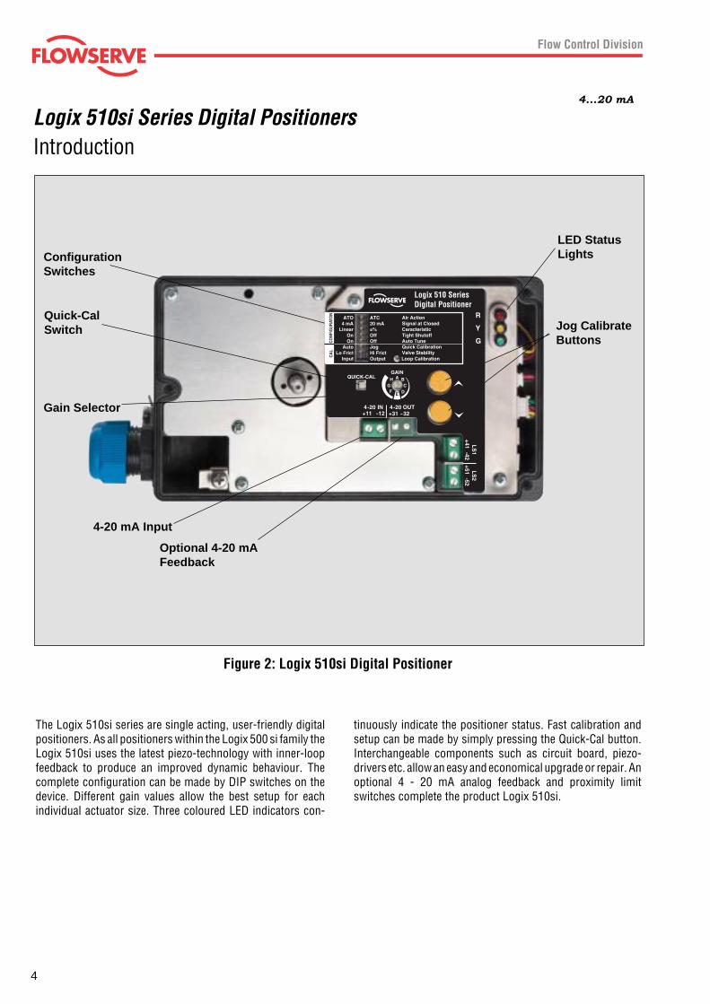
Figure 2: Logix 510si Digital Positioner
4...20 mA
The Logix 510si series are single acting, user-friendly digitalpositioners. As all positioners within the Logix 500 si family theLogix 510si uses the latest piezo-technology with inner-loopfeedback to produce an improved dynamic behaviour. Thecomplete configuration can be made by DIP switches on thedevice. Different gain values allow the best setup for eachindividual actuator size. Three coloured LED indicators con-
tinuously indicate the positioner status. Fast calibration andsetup can be made by simply pressing the Quick-Cal button.Interchangeable components such as circuit board, piezo-drivers etc. allow an easy and economical upgrade or repair. Anoptional 4 - 20 mA analog feedback and proximity limitswitches complete the product Logix 510si.
ConfigurationSwitches
4-20 mA Input
LED StatusLights
Jog CalibrateButtons
Optional 4-20 mAFeedback
Quick-CalSwitch
Gain Selector
5
Logix 510si Series Digital PositionersPrinciple of Operation
LocalUserInterface
4 – 20 mA
Inner LoopPiezo Control
Stroke
Inner LoopPosition Feedback
1 Digital Control Circuit
2 Electro-pneumatic Converter Module
3 Valve Position Sensor
Filter / Regulatorfor Supply Air
1.5 – 6.0 bar (22 – 87 psi)Air Supply
∑-
Micro- Processor
Gain
Pressure Regulator
Piezo ValvePneumaticAmplifier
Control Valve
+
4 – 20 mA
Input
Output(0ptional)
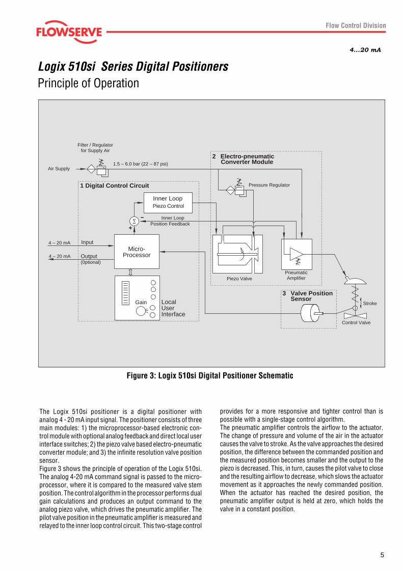
Figure 3: Logix 510si Digital Positioner Schematic
4...20 mA
The Logix 510si positioner is a digital positioner withanalog 4 - 20 mA input signal. The positioner consists of threemain modules: 1) the microprocessor-based electronic con-trol module with optional analog feedback and direct local userinterface switches; 2) the piezo valve based electro-pneumaticconverter module; and 3) the infinite resolution valve positionsensor.Figure 3 shows the principle of operation of the Logix 510si.The analog 4-20 mA command signal is passed to the micro-processor, where it is compared to the measured valve stemposition. The control algorithm in the processor performs dualgain calculations and produces an output command to theanalog piezo valve, which drives the pneumatic amplifier. Thepilot valve position in the pneumatic amplifier is measured andrelayed to the inner loop control circuit. This two-stage control
provides for a more responsive and tighter control than ispossible with a single-stage control algorithm.The pneumatic amplifier controls the airflow to the actuator.The change of pressure and volume of the air in the actuatorcauses the valve to stroke. As the valve approaches the desiredposition, the difference between the commanded position andthe measured position becomes smaller and the output to thepiezo is decreased. This, in turn, causes the pilot valve to closeand the resulting airflow to decrease, which slows the actuatormovement as it approaches the newly commanded position.When the actuator has reached the desired position, thepneumatic amplifier output is held at zero, which holds thevalve in a constant position.
6
Logix 510si Series Digital Positioners4...20 mA
Self Diagnostic Features
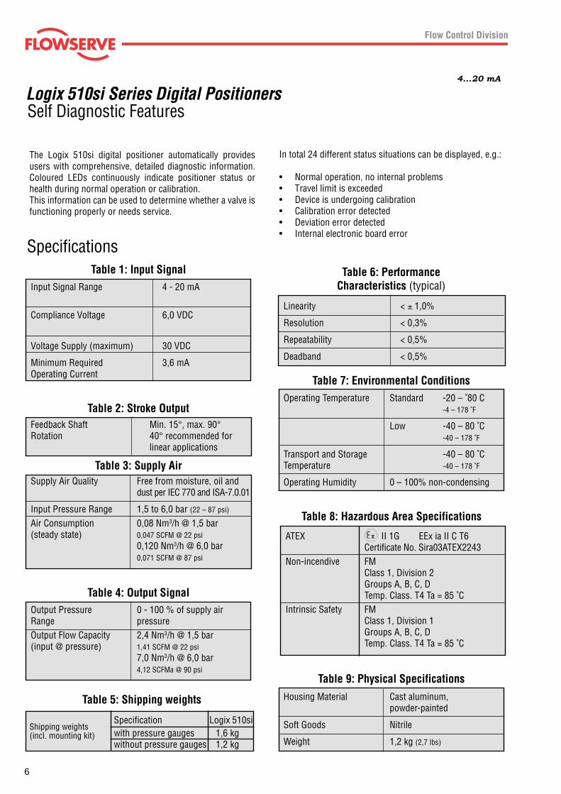
In total 24 different status situations can be displayed, e.g.:
• Normal operation, no internal problems• Travel limit is exceeded• Device is undergoing calibration• Calibration error detected• Deviation error detected• Internal electronic board error
The Logix 510si digital positioner automatically providesusers with comprehensive, detailed diagnostic information.Coloured LEDs continuously indicate positioner status orhealth during normal operation or calibration.This information can be used to determine whether a valve isfunctioning properly or needs service.
Specifications
Shipping weights(incl. mounting kit)
Linearity < ± 1,0%
Resolution < 0,3%
Repeatability < 0,5%
Deadband < 0,5%
Operating Temperature Standard -20 – ˚80 C-4 – 178 ˚F
Low -40 – 80 ˚C-40 – 178 ˚F
Transport and Storage -40 – 80 ˚CTemperature -40 – 178 ˚F
Operating Humidity 0 – 100% non-condensing
Input Signal Range 4 - 20 mA
Compliance Voltage 6,0 VDC
Voltage Supply (maximum) 30 VDC
Minimum Required 3,6 mAOperating Current
Table 1: Input Signal
Feedback Shaft Min. 15°, max. 90°Rotation 40° recommended for
linear applications
Table 2: Stroke Output
Supply Air Quality Free from moisture, oil anddust per IEC 770 and ISA-7.0.01
Input Pressure Range 1,5 to 6,0 bar (22 – 87 psi)
Air Consumption 0,08 Nm3/h @ 1,5 bar(steady state) 0,047 SCFM @ 22 psi
0,120 Nm3/h @ 6,0 bar0,071 SCFM @ 87 psi
Table 3: Supply Air
Output Pressure 0 - 100 % of supply airRange pressureOutput Flow Capacity 2,4 Nm3/h @ 1,5 bar(input @ pressure) 1,41 SCFM @ 22 psi
7,0 Nm3/h @ 6,0 bar4,12 SCFMa @ 90 psi
Table 4: Output Signal
Housing Material Cast aluminum,powder-painted
Soft Goods Nitrile
Weight 1,2 kg (2,7 lbs)
Table 9: Physical Specifications
Table 7: Environmental Conditions
Table 6: PerformanceCharacteristics (typical)
Specification Logix 510siwith pressure gauges 1,6 kgwithout pressure gauges 1,2 kg
Table 5: Shipping weights
ATEX II 1G EEx ia II C T6Certificate No. Sira03ATEX2243
Non-incendive FMClass 1, Division 2Groups A, B, C, DTemp. Class. T4 Ta = 85 ˚C
Intrinsic Safety FMClass 1, Division 1Groups A, B, C, DTemp. Class. T4 Ta = 85 ˚C
Table 8: Hazardous Area Specifications
7
Introduction
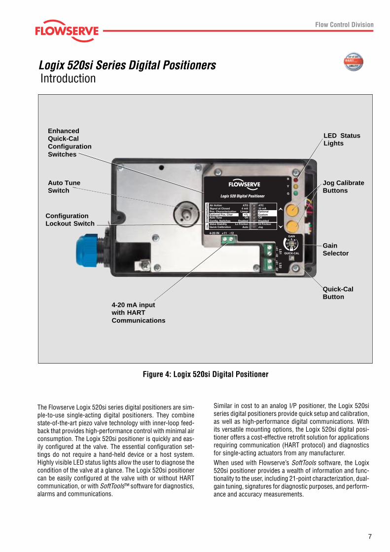
Figure 4: Logix 520si Digital Positioner
Similar in cost to an analog I/P positioner, the Logix 520siseries digital positioners provide quick setup and calibration,as well as high-performance digital communications. Withits versatile mounting options, the Logix 520si digital posi-tioner offers a cost-effective retrofit solution for applicationsrequiring communication (HART protocol) and diagnosticsfor single-acting actuators from any manufacturer.When used with Flowserve’s SoftTools software, the Logix520si positioner provides a wealth of information and func-tionality to the user, including 21-point characterization, dual-gain tuning, signatures for diagnostic purposes, and perform-ance and accuracy measurements.
The Flowserve Logix 520si series digital positioners are sim-ple-to-use single-acting digital positioners. They combinestate-of-the-art piezo valve technology with inner-loop feed-back that provides high-performance control with minimal airconsumption. The Logix 520si positioner is quickly and eas-ily configured at the valve. The essential configuration set-tings do not require a hand-held device or a host system.Highly visible LED status lights allow the user to diagnose thecondition of the valve at a glance. The Logix 520si positionercan be easily configured at the valve with or without HARTcommunication, or with SoftTools™ software for diagnostics,alarms and communications.
Logix 520si Series Digital Positioners
EnhancedQuick-CalConfigurationSwitches
Auto TuneSwitch
ConfigurationLockout Switch
4-20 mA inputwith HARTCommunications
LED StatusLights
Jog CalibrateButtons
GainSelector
Quick-CalButton
8
Principle of Operation
Local User Interface
4 – 20 mA+ HART HART
Inner LoopPiezo Control
Stroke
Inner LoopPosition Feedback
1 Digital Control Circuit
2 Electro-pneumatic Converter Module
3 Valve Position Sensor
Filter / Regulator for Supply Air
22 – 87 psi (1.5 – 6.0 bar)Supply Air
∑-
Micro Processor
Gain
Pressure Regulator
Piezo ValvePneumatic Amplifier
ControlValve
+
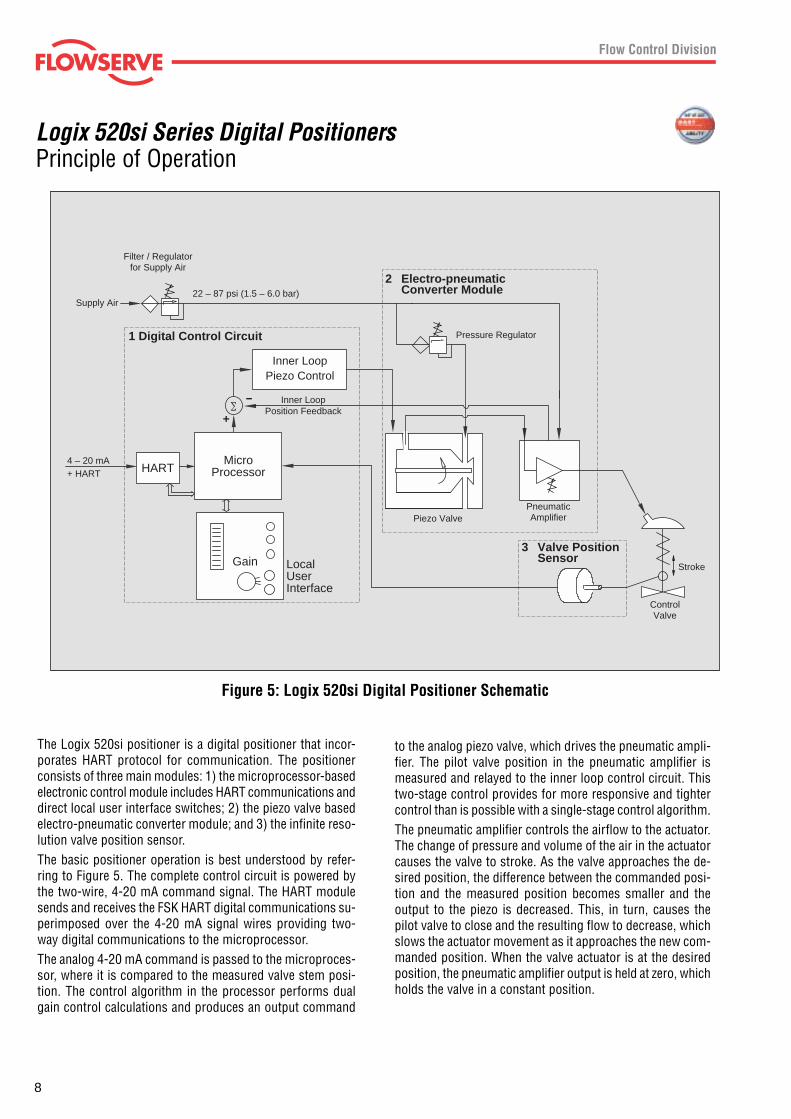
Figure 5: Logix 520si Digital Positioner Schematic
to the analog piezo valve, which drives the pneumatic ampli-fier. The pilot valve position in the pneumatic amplifier ismeasured and relayed to the inner loop control circuit. Thistwo-stage control provides for more responsive and tightercontrol than is possible with a single-stage control algorithm.The pneumatic amplifier controls the airflow to the actuator.The change of pressure and volume of the air in the actuatorcauses the valve to stroke. As the valve approaches the de-sired position, the difference between the commanded posi-tion and the measured position becomes smaller and theoutput to the piezo is decreased. This, in turn, causes thepilot valve to close and the resulting flow to decrease, whichslows the actuator movement as it approaches the new com-manded position. When the valve actuator is at the desiredposition, the pneumatic amplifier output is held at zero, whichholds the valve in a constant position.
The Logix 520si positioner is a digital positioner that incor-porates HART protocol for communication. The positionerconsists of three main modules: 1) the microprocessor-basedelectronic control module includes HART communications anddirect local user interface switches; 2) the piezo valve basedelectro-pneumatic converter module; and 3) the infinite reso-lution valve position sensor.The basic positioner operation is best understood by refer-ring to Figure 5. The complete control circuit is powered bythe two-wire, 4-20 mA command signal. The HART modulesends and receives the FSK HART digital communications su-perimposed over the 4-20 mA signal wires providing two-way digital communications to the microprocessor.The analog 4-20 mA command is passed to the microproces-sor, where it is compared to the measured valve stem posi-tion. The control algorithm in the processor performs dualgain control calculations and produces an output command
Logix 520si Series Digital Positioners
9
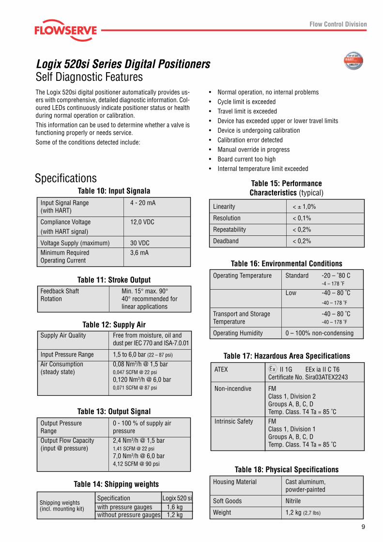
Self Diagnostic Features• Normal operation, no internal problems• Cycle limit is exceeded• Travel limit is exceeded• Device has exceeded upper or lower travel limits• Device is undergoing calibration• Calibration error detected• Manual override in progress• Board current too high• Internal temperature limit exceeded
The Logix 520si digital positioner automatically provides us-ers with comprehensive, detailed diagnostic information. Col-oured LEDs continuously indicate positioner status or healthduring normal operation or calibration.This information can be used to determine whether a valve isfunctioning properly or needs service.Some of the conditions detected include:
Logix 520si Series Digital Positioners
Shipping weights(incl. mounting kit)
Linearity < ± 1,0%
Resolution < 0,1%
Repeatability < 0,2%
Deadband < 0,2%
Operating Temperature Standard -20 – ˚80 C-4 – 178 ˚F
Low -40 – 80 ˚C-40 – 178 ˚F
Transport and Storage -40 – 80 ˚CTemperature -40 – 178 ˚F
Operating Humidity 0 – 100% non-condensing
Input Signal Range 4 - 20 mA(with HART)
Compliance Voltage 12,0 VDC(with HART signal)
Voltage Supply (maximum) 30 VDCMinimum Required 3,6 mAOperating Current
Table 10: Input Signala
Feedback Shaft Min. 15° max. 90°Rotation 40° recommended for
linear applications
Table 11: Stroke Output
Supply Air Quality Free from moisture, oil anddust per IEC 770 and ISA-7.0.01
Input Pressure Range 1,5 to 6,0 bar (22 – 87 psi)
Air Consumption 0,08 Nm3/h @ 1,5 bar(steady state) 0,047 SCFM @ 22 psi
0,120 Nm3/h @ 6,0 bar0,071 SCFM @ 87 psi
Table 12: Supply Air
Output Pressure 0 - 100 % of supply airRange pressureOutput Flow Capacity 2,4 Nm3/h @ 1,5 bar(input @ pressure) 1,41 SCFM @ 22 psi
7,0 Nm3/h @ 6,0 bar4,12 SCFM @ 90 psi
Table 13: Output Signal
Housing Material Cast aluminum,powder-painted
Soft Goods Nitrile
Weight 1,2 kg (2,7 lbs)
Table 18: Physical Specifications
Table 16: Environmental Conditions
Table 15: PerformanceCharacteristics (typical)
Specification Logix 520 siwith pressure gauges 1,6 kgwithout pressure gauges 1,2 kg
Table 14: Shipping weights
ATEX II 1G EEx ia II C T6Certificate No. Sira03ATEX2243
Non-incendive FMClass 1, Division 2Groups A, B, C, DTemp. Class. T4 Ta = 85 ˚C
Intrinsic Safety FMClass 1, Division 1Groups A, B, C, DTemp. Class. T4 Ta = 85 ˚C
Table 17: Hazardous Area Specifications
Specifications
10
SoftTools Interface
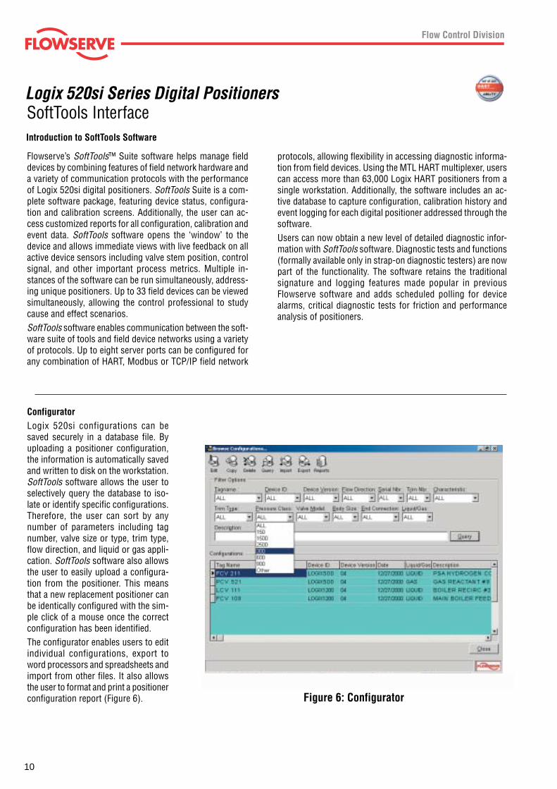
Figure 6: Configurator
Introduction to SoftTools Software
protocols, allowing flexibility in accessing diagnostic informa-tion from field devices. Using the MTL HART multiplexer, userscan access more than 63,000 Logix HART positioners from asingle workstation. Additionally, the software includes an ac-tive database to capture configuration, calibration history andevent logging for each digital positioner addressed through thesoftware.Users can now obtain a new level of detailed diagnostic infor-mation with SoftTools software. Diagnostic tests and functions(formally available only in strap-on diagnostic testers) are nowpart of the functionality. The software retains the traditionalsignature and logging features made popular in previousFlowserve software and adds scheduled polling for devicealarms, critical diagnostic tests for friction and performanceanalysis of positioners.
Flowserve’s SoftTools™ Suite software helps manage fielddevices by combining features of field network hardware anda variety of communication protocols with the performanceof Logix 520si digital positioners. SoftTools Suite is a com-plete software package, featuring device status, configura-tion and calibration screens. Additionally, the user can ac-cess customized reports for all configuration, calibration andevent data. SoftTools software opens the ‘window’ to thedevice and allows immediate views with live feedback on allactive device sensors including valve stem position, controlsignal, and other important process metrics. Multiple in-stances of the software can be run simultaneously, address-ing unique positioners. Up to 33 field devices can be viewedsimultaneously, allowing the control professional to studycause and effect scenarios.SoftTools software enables communication between the soft-ware suite of tools and field device networks using a varietyof protocols. Up to eight server ports can be configured forany combination of HART, Modbus or TCP/IP field network
ConfiguratorLogix 520si configurations can besaved securely in a database file. Byuploading a positioner configuration,the information is automatically savedand written to disk on the workstation.SoftTools software allows the user toselectively query the database to iso-late or identify specific configurations.Therefore, the user can sort by anynumber of parameters including tagnumber, valve size or type, trim type,flow direction, and liquid or gas appli-cation. SoftTools software also allowsthe user to easily upload a configura-tion from the positioner. This meansthat a new replacement positioner canbe identically configured with the sim-ple click of a mouse once the correctconfiguration has been identified.The configurator enables users to editindividual configurations, export toword processors and spreadsheets andimport from other files. It also allowsthe user to format and print a positionerconfiguration report (Figure 6).
Logix 520si Series Digital Positioners
11
SoftTools Interface
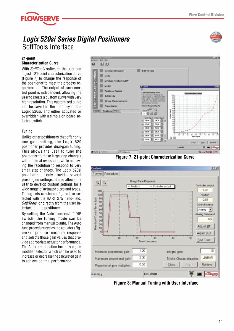
Figure 7: 21-point Characterization Curve
Figure 8: Manual Tuning with User Interface
21-pointCharacterization CurveWith SoftTools software, the user canadjust a 21-point characterization curve(Figure 7) to change the response ofthe positioner to meet the process re-quirements. The output of each con-trol point is independent, allowing theuser to create a custom curve with veryhigh resolution. This customized curvecan be saved in the memory of theLogix 520si, and either activated oroverridden with a simple on board se-lector switch.
TuningUnlike other positioners that offer onlyone gain setting, the Logix 520positioner provides dual-gain tuning.This allows the user to tune thepositioner to make large step changeswith minimal overshoot, while achiev-ing the resolution to respond to verysmall step changes. The Logix 520sipositioner not only provides severalpreset gain settings, it also allows theuser to develop custom settings for awide range of actuator sizes and types.Tuning sets can be configured, or se-lected with the HART 275 hand-held,SoftTools, or directly from the user in-terface on the positioner.By setting the Auto tune on/off DIPswitch, the tuning mode can bechanged from manual to auto. The Autotune procedure cycles the actuator (Fig-ure 8) to produce a measured responseand selects those gain values that pro-vide appropriate actuator performance.The Auto tune function includes a gainmodifier selector which can be used toincrease or decrease the calculated gainto achieve optimal performance.
Logix 520si Series Digital Positioners
12
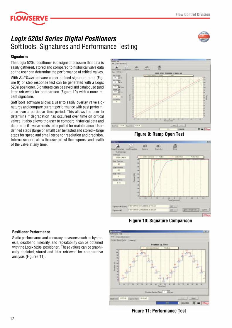
Positioner PerformanceStatic performance and accuracy measures such as hyster-esis, deadband, linearity, and repeatability can be obtainedwith the Logix 520si positioner,. These values can be graphi-cally depicted, stored and later retrieved for comparativeanalysis (Figures 11).
SoftTools, Signatures and Performance Testing
Figure 10: Signature Comparison
SignaturesThe Logix 520si positioner is designed to assure that data iseasily gathered, stored and compared to historical valve dataso the user can determine the performance of critical valves.With SoftTools software a user-defined signature ramp (Fig-ure 9) or step response test can be generated with a Logix520si positioner. Signatures can be saved and catalogued (andlater retrieved) for comparison (Figure 10) with a more re-cent signature.SoftTools software allows a user to easily overlay valve sig-natures and compare current performance with past perform-ance over a particular time period. This allows the user todetermine if degradation has occurred over time on criticalvalves. It also allows the user to compare historical data anddetermine if a valve needs to be pulled for maintenance. User-defined steps (large or small) can be tested and stored – largesteps for speed and small steps for resolution and precision.Internal sensors allow the user to test the response and healthof the valve at any time.
Logix 520si Series Digital Positioners
Figure 9: Ramp Open Test
Figure 11: Performance Test
13
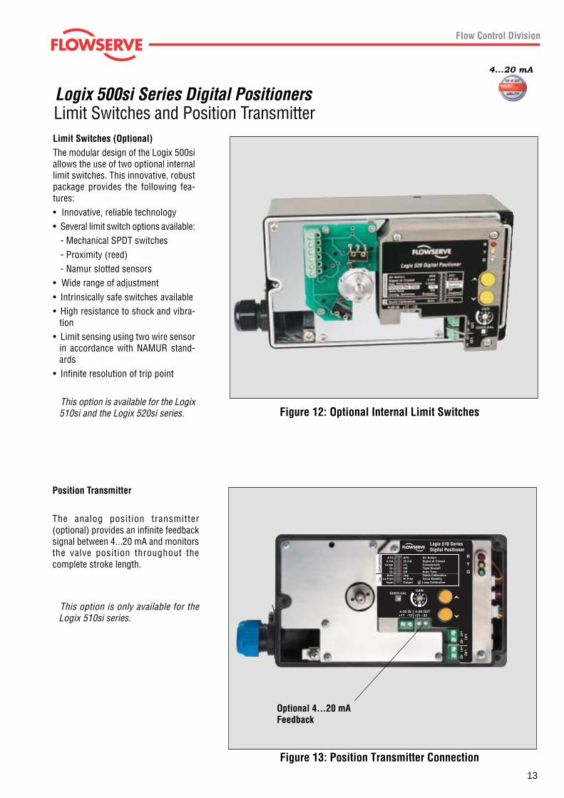
Limit Switches and Position Transmitter
Figure 12: Optional Internal Limit Switches
Limit Switches (Optional)The modular design of the Logix 500siallows the use of two optional internallimit switches. This innovative, robustpackage provides the following fea-tures:• Innovative, reliable technology• Several limit switch options available:
- Mechanical SPDT switches- Proximity (reed)- Namur slotted sensors
• Wide range of adjustment• Intrinsically safe switches available• High resistance to shock and vibra-
tion• Limit sensing using two wire sensor
in accordance with NAMUR stand-ards
• Infinite resolution of trip point
This option is available for the Logix510si and the Logix 520si series.
Logix 500si Series Digital Positioners
4...20 mA
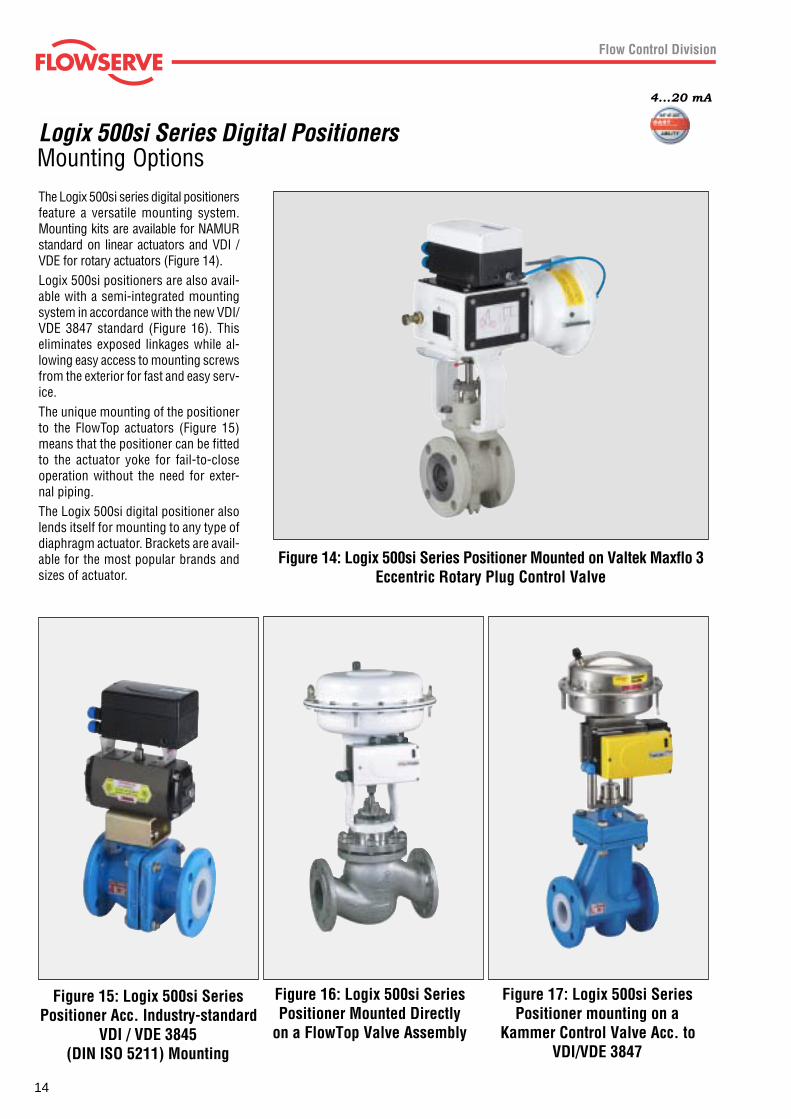
Position Transmitter
The analog position transmitter(optional) provides an infinite feedbacksignal between 4...20 mA and monitorsthe valve position throughout thecomplete stroke length.
This option is only available for theLogix 510si series.
Optional 4...20 mAFeedback
Figure 13: Position Transmitter Connection
14
Mounting Options
Figure 14: Logix 500si Series Positioner Mounted on Valtek Maxflo 3Eccentric Rotary Plug Control Valve
Figure 15: Logix 500si SeriesPositioner Acc. Industry-standard
VDI / VDE 3845(DIN ISO 5211) Mounting
Figure 17: Logix 500si SeriesPositioner mounting on a
Kammer Control Valve Acc. toVDI/VDE 3847
Figure 16: Logix 500si SeriesPositioner Mounted Directly
on a FlowTop Valve Assembly
The Logix 500si series digital positionersfeature a versatile mounting system.Mounting kits are available for NAMURstandard on linear actuators and VDI /VDE for rotary actuators (Figure 14).Logix 500si positioners are also avail-able with a semi-integrated mountingsystem in accordance with the new VDI/VDE 3847 standard (Figure 16). Thiseliminates exposed linkages while al-lowing easy access to mounting screwsfrom the exterior for fast and easy serv-ice.The unique mounting of the positionerto the FlowTop actuators (Figure 15)means that the positioner can be fittedto the actuator yoke for fail-to-closeoperation without the need for exter-nal piping.The Logix 500si digital positioner alsolends itself for mounting to any type ofdiaphragm actuator. Brackets are avail-able for the most popular brands andsizes of actuator.
Logix 500si Series Digital Positioners
4...20 mA
15
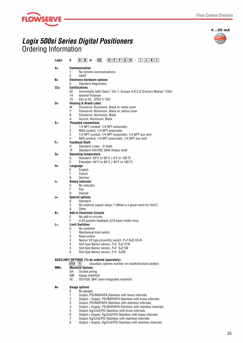
Ordering InformationLogix 500si Series Digital Positioners
4...20 mA
Logix 5 A B si - CC - D E F G H - I J K L
A= Communication1 No remote communications2 HART
B= Electronic hardware options0 Standard diagnostics
CC= Certifications02 Intrinsically Safe Class I, Div 1, Groups A,B,C,D (Factory Mutual / CSA)14 General Purpose15 EEx ia IIC, ATEX II 1GD
D= Housing & Brand LabelW Flowserve: Aluminum, Black w/ white coverY Flowserve: Aluminum, Black w/ yellow coverB Flowserve: Aluminum, BlackA Accord: Aluminum, Black
E= Threaded connections1 1/2 NPT conduit, 1/4 NPT pneumatic2 M20 conduit, 1/4 NPT pneumatic3 1/2 NPT conduit, 1/4 NPT pneumatic, 1/4 NPT aux vent4 M20 conduit, 1/4 NPT pneumatic, 1/4 NPT aux vent
F= Feedback ShaftD Standard Linear - D shaft R Standard VDI/VDE 3845 Rotary shaft
G= Operating temperatureS Standard -20°C to 85°C (-4°F to 185°F)E Extended -40°C to 85°C (-40°F to 185°F)
H= LanguageE EnglishF FrenchG German
I= Rotary Indicator0 No indicatorF FlatD Domed
J= Special options0 Standard5 No external copper alloys ? (What is a good name for this?)9 Other
K= Add-in Electronic Circuits0 No add-in circuitsF 4-20 positon feedback (510 base model now)
L= Limit Switches0 No switches1 Mechanical limit switch2 Reed switch3 Namur V3 type proximity switch, P+F NJ2-V3-N4 Slot type Namur sensor, P+F SJ2 S1N5 Slot type Namur sensor, P+F SJ2 SN6 Slot type Namur sensor, P+F SJ2N
AUXILIARY OPTIONS (To be ordered separately)MM N (Auxiliary options number on manifold block sticker)
MM= Manifold OptionsDA Double actingGM Gauge manifoldVE VDI/VDE 3847 semi-integrated manifold
N= Gauge options0 No gauges1 Output, PSI/BAR/KPA Stainless with brass internals2 Output + Supply, PSI/BAR/KPA Stainless with brass internals3 Output, PSI/BAR/KPA Stainless with stainless internals4 Output + Supply, PSI/BAR/KPA Stainless with stainless internals5 Output, Kg/Cm2/PSI Stainless with brass internals6 Output + Supply, Kg/Cm2/PSI Stainless with brass internals7 Output, Kg/Cm2/PSI Stainless with stainless internals8 Output + Supply, Kg/Cm2/PSI Stainless with stainless internals
Logix 500si Series Digital Positioners
All data subject to change without notice©07.2003 Flowserve Corporation. Flowserve and Kämmer are trademarks of Flowserve Corporation
Regional Headquarters
Manderscheidstr. 19 1350 N. Mt. Springs Prkwy. 12 Tuas Avenue 2045141 Essen Springville, UT 84663Germany USA Republic of Singapore 638824Telephone: +49 (0) 201 8919 5 Telephone: +1 801 489 8611 Telephone: +65 862 3332Facsimile: +49 (0) 201 8919 662 Facsimile: +1 801 489 3719 Facsimile: +65 862 4940
Main Sales Offices (Europe, Middle East, Africa)
von-Braun-Straße 19a 12, av. du Québec Station Road Allee du Quartz 148681 Ahaus 91965, Courtaboeuf Cedex Pershore, Worcestershire CH-2300 La-Chaux-de FondsGermany France England WR102BZ SwitzerlandTelephone: +49 (0) 2561 6860 Telephone: +33 (0) 1 60 923 251 Telephone: +44 (0) 1386 55 45 51 Telephone: +41 (0) 32 925 9700Facsimile: +49 (0) 2561 68648 Facsimile: +33 (0) 1 60 923 299 Facsimile: +44 (0) 1386 55 49 68 Facsimile: +41 (0) 32 926 5422
Cnr Bismit and Granier Street C/O Saleh & Abdulaziz AbahsainJet Park Ext 3 P.O. Box 209Boksburg,1459 Gauteng Al Khobar 31952South Africa Saudi ArabiaTelephone: +27 397-3150 Telephone: 9663 857 3442Facsimile: +27 397-5300/01/02 Facsimile: 9663 859 5284
ADK0
4130
0E -
07.0
3
4...20 mA
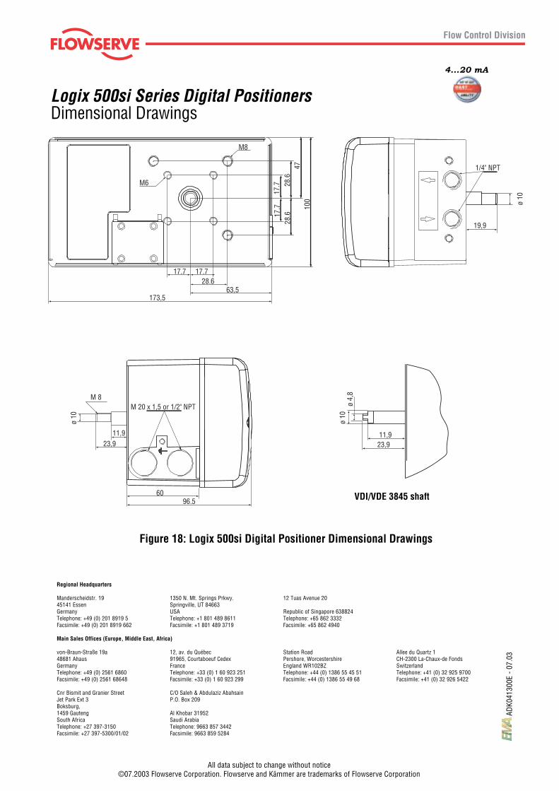
Figure 18: Logix 500si Digital Positioner Dimensional Drawings
M8
M6
17.7 17.728.6
63,5173,5
17.7
17.7
28.6
28.6
4710
0
1/4" NPT
ø 10
ø 4,
8
11,923,9
ø 10
19,9
ø 10
M 8
11,923,9
M 20 x 1,5 or 1/2" NPT
6096.5 VDI/VDE 3845 shaft
Dimensional Drawings