Embed Size (px)
Citation preview
®
SUPERWORKSTATION 7034A-TSUPERWORKSTATION 7034A-i
USER’S MANUAL
1.0
SUPER

The information in this User’s Manual has been carefully reviewed and is believed to beaccurate. The vendor assumes no responsibility for any inaccuracies that may becontained in this document, makes no commitment to update or to keep current theinformation in this manual, or to notify any person or organization of the updates. PleaseNote: For the most up-to-date version of this manual, please see ourweb site at www.supermicro.com.
SUPERMICRO COMPUTER reserves the right to make changes to the product described inthis manual at any time and without notice. This product, including software, if any, anddocumentation may not, in whole or in part, be copied, photocopied, reproduced, translatedor reduced to any medium or machine without prior written consent.
IN NO EVENT WILL SUPERMICRO COMPUTER BE LIABLE FOR DIRECT, INDIRECT,SPECIAL, INCIDENTAL, SPECULATIVE OR CONSEQUENTIAL DAMAGES ARISING FROMTHE USE OR INABILITY TO USE THIS PRODUCT OR DOCUMENTATION, EVEN IFADVISED OF THE POSSIBILITY OF SUCH DAMAGES. IN PARTICULAR, THE VENDORSHALL NOT HAVE LIABILITY FOR ANY HARDWARE, SOFTWARE, OR DATA STOREDOR USED WITH THE PRODUCT, INCLUDING THE COSTS OF REPAIRING, REPLACING,INTEGRATING, INSTALLING OR RECOVERING SUCH HARDWARE, SOFTWARE, ORDATA.
Any disputes arising between manufacturer and customer shall be governed by the laws ofSanta Clara County in the State of California, USA. The State of California, County ofSanta Clara shall be the exclusive venue for the resolution of any such disputes.Supermicro's total liability for all claims will not exceed the price paid for the hardwareproduct.
Unless you request and receive written permission from SUPER MICRO COMPUTER,you may not copy any part of this document.
Information in this document is subject to change without notice. Other products andcompanies referred to herein are trademarks or registered trademarks of their respectivecompanies or mark holders.
Copyright © 2004 by SUPER MICRO COMPUTER INC.All rights reserved.Printed in the United States of America
i i i
Preface
Preface
About This Manual
This manual is written for professional system integrators and PC technicians.It provides information for the installation and use of the SuperWorkstation 7034A-T/7034A-i. Installation and maintainance should be performed by experiencedtechnicians only.
The SuperWorkstation 7034A-T/7034A-i is a high-end, dual processor towerworkstation based on the SC733T-645/SC733i-645 chassis and the X6DAL-TG/X6DAL-G, a dual processor serverboard that supports single or dual Intel XeonTM
processors at a Front Side (System) Bus speed of 800 MHz and up to 12/24 GBof registered ECC DDR333/266 SDRAM.
Manual Organization
Chapter 1: Introduction
The first chapter provides a checklist of the main components included with theserver system and describes the main features of the X6DAL-TG/X6DAL-Gserverboard and the SC733T-645/SC733i-645 chassis, which comprise theSuperWorkstation 7034A-T/7034A-i.
Chapter 2: Server Installation
This chapter describes the steps necessary to set up and check out the configu-ration of the SuperWorkstation 7034A-T/7034A-i prior to powering up the system.If your system was ordered without processor and memory components, thischapter will refer you to the appropriate sections of the manual for their instal-lation.
Chapter 3: System Interface
Refer here for details on the system interface, which includes the functions andinformation provided by the control panel on the chassis as well as other LEDslocated throughout the system.
iv
Chapter 4: System Safety
You should thoroughly familiarize yourself with this chapter for a generaloverview of safety precautions that should be followed when installing andservicing the SuperWorkstation 7034A-T/7034A-i.
Chapter 5: Advanced Serverboard Setup
Chapter 5 provides detailed information on the X6DAL-TG/X6DAL-Gserverboard, including the locations and functions of connections, headersand jumpers. Refer to this chapter when adding or removing processors ormain memory, when adding peripheral drives and when reconfiguring theserverboard.
Chapter 6: Advanced Chassis Setup
Refer to Chapter 6 for detailed information on the SC733T-645/SC733i-645server chassis. You should follow the procedures given in this chapterwhen installing, removing or reconfiguring peripheral drives and when re-placing system power supply units and cooling fans.
Chapter 7: BIOS
The BIOS chapter includes an introduction to BIOS and provides detailedinformation on running the CMOS Setup Utility.
Appendix A: BIOS Error Beep/POST Codes
Appendix B: BIOS POST Checkpoint Codes
Appendix C: System Specifications
SUPERWORKSTATION 7034A-T/7034A-i Manual

v
Preface
Notes
vi
Table of Contents
PrefaceAbout This Manual ...................................................................................................... iiiManual Organization ................................................................................................... iii
Chapter 1: Introduction1-1 Overview ......................................................................................................... 1-11-2 Serverboard Features ................................................................................... 1-21-3 Server Chassis Features .............................................................................. 1-31-4 Contacting Supermicro .................................................................................. 1-5
Chapter 2: Server Installation2-1 Overview ......................................................................................................... 2-12-2 Unpacking the System ................................................................................... 2-12-3 Preparing for Setup ....................................................................................... 2-12-4 Checking the Serverboard Setup ................................................................ 2-22-5 Checking the Drive Bay Setup ..................................................................... 2-4
Chapter 3: System Interface3-1 Overview ......................................................................................................... 3-13-2 Control Panel Buttons .................................................................................... 3-1
Power ........................................................................................................ 3-1Reset .......................................................................................................... 3-1
3-3 Control Panel LEDs ........................................................................................ 3-2Power ........................................................................................................ 3-2HDD ............................................................................................................ 3-2NIC .............................................................................................................. 3-2Overheat/Fan Fail .................................................................................... 3-2Power Fail ................................................................................................. 3-3
3-4 LAN (Ethernet) Port LEDs ............................................................................. 3-3
Chapter 4: System Safety4-1 Electrical Safety Precautions ....................................................................... 4-14-2 General Safety Precautions ......................................................................... 4-24-3 ESD Safety Precautions ................................................................................ 4-34-4 Operating Precautions ................................................................................... 4-4
SUPERWORKSTATION 7034A-T/7034A-i Manual
Chapter 5: Advanced Serverboard Setup5-1 Handling the Serverboard ............................................................................. 5-15-2 Processor and Heatsink Installation ............................................................ 5-25-3 Connecting Cables ......................................................................................... 5-5
Connecting Data Cables ......................................................................... 5-5Connecting Power Cables ...................................................................... 5-5Connecting the Control Panel ................................................................ 5-6
5-4 I/O Ports ........................................................................................................... 5-75-5 Installing Memory ............................................................................................ 5-75-6 Adding PCI Cards ........................................................................................... 5-95-7 Serverboard Details ..................................................................................... 5-10
X6DAL-TG/X6DAL-G Layout ................................................................ 5-10X6DAL-TG/X6DAL-G Quick Reference .............................................. 5-11
5-8 Connector Definitions .................................................................................. 5-12ATX Power Connector .......................................................................... 5-12Processor Power Connector ............................................................... 5-12NMI Button ............................................................................................... 5-12Power LED .............................................................................................. 5-12HDD LED .................................................................................................. 5-13NIC LED ..................................................................................................... 5-13Overheat/Fan Fail LED .......................................................................... 5-13Power Fail LED ...................................................................................... 5-13GLAN1 (Ethernet Port) .......................................................................... 5-13Reset Button ........................................................................................... 5-14Power Button .......................................................................................... 5-14Chassis Intrusion .................................................................................... 5-14Universal Serial Bus (USB0/1) ............................................................ 5-14Fan Headers ........................................................................................... 5-15Serial Ports ............................................................................................. 5-15ATX PS/2 Keyboard and Mouse Ports ............................................... 5-15Power LED/Speaker/Keylock ............................................................... 5-16Wake-On-Ring ........................................................................................ 5-16Wake-On-LAN ........................................................................................ 5-16SATA LED ............................................................................................... 5-16Power Fault ............................................................................................ 5-17SATA SMB (I2C) ..................................................................................... 5-17SMB Power Connector ......................................................................... 5-17CD-In Headers ........................................................................................ 5-17
vii
Table of Contents
viii
5-9 Jumper Settings ............................................................................................ 5-18Explanation of Jumpers ........................................................................ 5-18CMOS Clear ............................................................................................. 5-18Serial ATA Enable/Disable ................................................................... 5-18GLAN Enable/Disable ............................................................................. 5-19Audio Enable/Disable ............................................................................. 5-19Alarm Reset ............................................................................................ 5-19Power Force On Enable/Disable ......................................................... 5-19Watch Dog Enable/Disable ................................................................... 5-20AC'97 Audio Enable/Disable ................................................................. 5-20
5-10 Onboard Indicators ...................................................................................... 5-21LAN LEDs ................................................................................................ 5-21Onboard LED Indicators ....................................................................... 5-21System Alert LED Indicators ................................................................ 5-21
5-11 Floppy and Hard Disk Drive Connections ................................................ 5-22Floppy Connector ................................................................................... 5-22IDE Connectors ...................................................................................... 5-23
Chapter 6: Advanced Chassis Setup6-1 Static-Sensitive Devices ............................................................................... 6-16-2 Front Control Panel ........................................................................................ 6-26-3 System Fans ................................................................................................... 6-5
Fan Failure ................................................................................................ 6-5Replacing System Fans .......................................................................... 6-5
6-4 Drive Bay Installation ..................................................................................... 6-7Serial ATA Drives .................................................................................... 6-7Installing Components in the 5.25" Drive Bays ................................ 6-10
6-5 Power Supply ............................................................................................... 6-11Power Supply Failure ........................................................................... 6-11Replacing the Power Supply ............................................................... 6-11
Chapter 7: BIOS7-1 Introduction ...................................................................................................... 7-17-2 Main Setup ....................................................................................................... 7-27-3 Advanced Settings ........................................................................................ 7-37-4 Security Settings .......................................................................................... 7-237-5 Exit Options ................................................................................................... 7-24
SUPERWORKSTATION 7034A-T/7034A-i Manual

Table of Contents
ix
Appendices:Appendix A: BIOS Error Beep/POST Codes ....................................................... A-1Appendix B: BIOS POST Checkpoint Codes ....................................................... B-1Appendix C: System Specifications .................................................................... C-1

Notes
x
SUPERWORKSTATION 7034A-T/7034A-i Manual

Chapter 1
Introduction
1-1 Overview
The Supermicro SuperWorkstation 7034A-T/7034A-i is a high-end, dual proces-sor workstation in a tower configuration. The 7034A-T/7034A-i is comprised oftwo main subsystems: the SC733T-645/SC733i-645 high-end server chassis andthe X6DAL-TG/X6DAL-G Intel® XeonTM dual processor serverboard. Please referto our web site for information on operating systems that have been certified foruse with the SuperWorkstation 7034A-T/7034A-i.
In addition to the serverboard and chassis, various hardware components havebeen included with the 7034A-T/7034A-i, as listed below:
One (1) 3.5" floppy drive [FPD-TEAC (B)]
One (1) 9-cm chassis fan (FAN-0076)
One (1) 12-cm exhaust fan (FAN-0077)
Two (2) 5.25" dummy IDE disk drive trays [CSE-PT36(B)-OEM]
One (1) front control panel cable (CBL-0049)
One (1) round floppy drive cable (CBL-0051)
One (1) round CD-ROM cable (CBL-0052)
One (1) I/O shield (CSE-PT2)
SATA Accessories (7034A-T only)
One (1) SATA backplane (CSE-SATA-733)
Four (4) SATA cables (CBL-0044)
One (1) 10-pin to 10-pin SATA LED cable (CBL-0056)
Four (4) 1-inch high SATA drive carriers [CSE-PT-39(B)]
Optional: Two (2) Xeon 4-wire active heatsinks (SNK-P0008A4)
Chapter 1: Introduction
1-1
1-2
SUPERWORKSTATION 7034A-T/7034A-i Manual
1-2 Serverboard Features
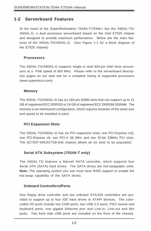
At the heart of the SuperWorkstation 7034A-T/7034A-i lies the X6DAL-TG/X6DAL-G, a dual processor serverboard based on the Intel E7525 chipsetand designed to provide maximum performance. Below are the main fea-tures of the X6DAL-TG/X6DAL-G. (See Figure 1-1 for a block diagram ofthe E7525 chipset).
Processors
The X6DAL-TG/X6DAL-G supports single or dual 604-pin Intel Xeon proces-sors at a FSB speed of 800 MHz. Please refer to the serverboard descrip-tion pages on our web site for a complete listing of supported processors(www.supermicro.com).
Memory
The X6DAL-TG/X6DAL-G has six 184-pin DIMM slots that can support up to 12GB of registered ECC DDR333 or 24 GB of registered ECC DDR266 SDRAM. Thememory is an interleaved configuration, which requires modules of the same sizeand speed to be installed in pairs.
PCI Expansion Slots
The X6DAL-TG/X6DAL-G has six PCI expansion slots: one PCI-Express x16,one PCI-Express x8, two PCI-X 66 MHz and two 32-bit 33MHz PCI slots.The SC733T-645/SC733i-645 chassis allows all six slots to be populated.
Serial ATA Subsystem (7034A-T only)
The X6DAL-TG features a Marvell SATA controller, which supports fourSerial ATA (SATA) hard drives. The SATA drives are hot-swappable units.Note: The operating system you use must have RAID support to enable thehot-swap capability of the SATA drives.
Onboard Controllers/Ports
One floppy drive controller and two onboard ATA/100 controllers are pro-vided to support up to four IDE hard drives or ATAPI devices. The color-coded I/O ports include two COM ports, two USB 2.0 ports, PS/2 mouse andkeyboard ports, one gigabit Ethernet port and Line-in, Line-out and Micjacks. Two front side USB ports are included on the front of the chassis.
1-3
Chapter 1: Introduction
1-3 Server Chassis Features
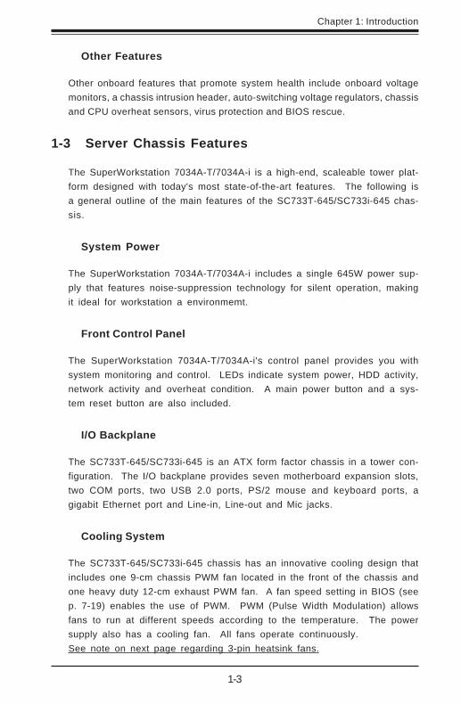
The SuperWorkstation 7034A-T/7034A-i is a high-end, scaleable tower plat-form designed with today's most state-of-the-art features. The following isa general outline of the main features of the SC733T-645/SC733i-645 chas-sis.
System Power
The SuperWorkstation 7034A-T/7034A-i includes a single 645W power sup-ply that features noise-suppression technology for silent operation, makingit ideal for workstation a environmemt.
Front Control Panel
The SuperWorkstation 7034A-T/7034A-i's control panel provides you withsystem monitoring and control. LEDs indicate system power, HDD activity,network activity and overheat condition. A main power button and a sys-tem reset button are also included.
I/O Backplane
The SC733T-645/SC733i-645 is an ATX form factor chassis in a tower con-figuration. The I/O backplane provides seven motherboard expansion slots,two COM ports, two USB 2.0 ports, PS/2 mouse and keyboard ports, agigabit Ethernet port and Line-in, Line-out and Mic jacks.
Cooling System
The SC733T-645/SC733i-645 chassis has an innovative cooling design thatincludes one 9-cm chassis PWM fan located in the front of the chassis andone heavy duty 12-cm exhaust PWM fan. A fan speed setting in BIOS (seep. 7-19) enables the use of PWM. PWM (Pulse Width Modulation) allowsfans to run at different speeds according to the temperature. The powersupply also has a cooling fan. All fans operate continuously.See note on next page regarding 3-pin heatsink fans.
Other Features
Other onboard features that promote system health include onboard voltagemonitors, a chassis intrusion header, auto-switching voltage regulators, chassisand CPU overheat sensors, virus protection and BIOS rescue.

1-4
SUPERWORKSTATION 7034A-T/7034A-i Manual
Figure 1-1. Intel E7525 Chipset:System Block Diagram
Note: This is a general block diagram. Please see Chapter 5 for details.
MCH
NOCONA PROCE S SOR#2VRM CL OCK
AD
DR
CT
RL
DA
TA
NOCONA PROCE S SOR#1
AD
DR
CT
RL
DA
TA
DA
TA
AD
DR
CT
RL
I CH5R
HUB
DDRI I - 400
A
PXH
B
PCI E XP. A
1 PCI - X
S L OT 31 PCI - X
PCI - X BUS ( 100 MHZ)
Gbi t L AN
S L OT 2J 13
PCI - X BUS ( 100 MHZ)
J 14 1 PCI - E XPS L OT 4J 17
PCI E XP. B, C ( X16)
J 15
1 PCI - E XPS L OT 6
DI MMs
I DE
PRI / S E C
UDMA/ 100
X8X4
X4DI MMs
0, 1
SATA SATA
L PC BUSUS BUS B PORT0, 1, 2, 3,
BMC CON. F WHL PC I / O
PARAL L EL PORTMS .
F DD. S E R. 1S E R. 2
KB.
4 DDR I I - 400
4 DDR I I - 400DDRI I - 400
S CS I
7902
PCI BUS ( 32- BI T) PCI 32 BI TS L OT 5
AC 97
J 19
1 PCI - XS L OT 1J 12
H/ WMONI TOR
5, 6, 7, 8
Note: the 4-pin fan headers on the 7034A-T/7034A-i serverboard may presentsome confusion to users who decide to add CPU heatsinks that have 3-pin fanheaders. Heatsinks with 3-pin fan headers may be connected to the serverboard,but these fans will not be controlled by PWM and will constantly run at full speed,which may generate too much noise for the workspace. To remedy this,Supermicro suggests changing the “Auto Fan control” BIOS setting to “3-pinWorkstation”, which will cause fan speed to be controlled by temperature
sensor/voltage levels and result in lower noise levels.

1-5
Chapter 1: Introduction
1-4 Contacting Supermicro
HeadquartersAddress: SuperMicro Computer, Inc.
980 Rock Ave.San Jose, CA 95131 U.S.A.
Tel: +1 (408) 503-8000Fax: +1 (408) 503-8008Email: [email protected] (General Information)
[email protected] (Technical Support)Web Site: www.supermicro.com
EuropeAddress: SuperMicro Computer B.V.
Het Sterrenbeeld 28, 5215 ML's-Hertogenbosch, The Netherlands
Tel: +31 (0) 73-6400390Fax: +31 (0) 73-6416525Email: [email protected] (General Information)
[email protected] (Technical Support)[email protected] (Customer Support)
Asia-PacificAddress: SuperMicro, Taiwan
D5, 4F, No. 16 Chien-Ba RoadChung-Ho 235, Taipei Hsien, Taiwan, R.O.C.
Tel: +886-(2) 8226-3990Fax: +886-(2) 8226-3991Web Site: www.supermicro.com.twTechnical Support:Email: [email protected]: 886-2-8228-1366, ext.132 or 139

1-6
SUPERWORKSTATION 7034A-T/7034A-i Manual
Notes
Chapter 2: Server Installation
2-1
Chapter 2
Server Installation
2-1 Overview
This chapter provides a quick setup checklist to get your SuperWorkstation7034A-T/7034A-i up and running. Following these steps in the order given shouldenable you to have the system operational in a minimal amount of time. Thisquick setup assumes that your SuperWorkstation 7034A-T/7034A-i system hascome to you with the processors and memory preinstalled. If your system is notalready fully integrated with a motherboard, processors, system memory etc.,please turn to the chapter or section noted in each step for details on installingspecific components.
2-2 Unpacking the System
You should inspect the box the SuperWorkstation 7034A-T/7034A-i was shippedin and note if it was damaged in any way. If the workstation itself shows damageyou should file a damage claim with the carrier who delivered it.
2-3 Preparing for Setup
Choosing a Setup Location
Decide on a suitable location for the SuperWorkstation 7034A-T/7034A-i. Itshould be situated in a clean, dust-free area that is well ventilated. Avoid areaswhere heat, electrical noise and electromagnetic fields are generated. You willalso need it placed near a grounded power outlet. Once the system has beenplaced in the appropriate location, slide the locking tabs on each caster down tokeep it stationary.
2-2
SUPERWORKSTATION 7034A-T/7034A-i Manual
Server Precautions
- Review the electrical and general safety precautions in Chapter 4.- Use a regulating uninterruptible power supply (UPS) to protect the
server from power surges, voltage spikes and to keep your system operating in case of a power failure.
- Allow the power supply unit and the SATA hard drives (7034A-T only) to coolbefore touching them.
- Always keep the chassis front door and all panels closed when not ser-vicing to maintain proper cooling.
2-4 Checking the Serverboard Setup
After setting up the the 7034A-T/7034A-i, you will need to gain access to theinside of the chassis to make sure the serverboard is properly installed and theessential connections have been made. Begin by opening the left side panel(when facing the front of the chassis). Refer to Figure 2-1 for the following steps.
1. Remove the left side panel of the chassisFirst, remove the two screws that secure the back lip of the side panel to therear of the chassis. Then grasp the handle at the rear of the panel and pullstraight back about 1/2 inch, at which point the panel should hit a stop. Swingthe top of the panel out and completely lift it away from the chassis. Whenreinstalling this panel, make sure the raised holes along the bottom of thechassis fit into the long holes in the bottom lip of the side panel.
2. Check the CPUs (processors)You should have one or two processors already installed into the systemboard. Each processor should have its own heatsink attached. See Chapter5 for instructions on processor installation.
3. Check the system memoryYour 7034A-T/7034A-i workstation may have come with system memory al-ready installed. Make sure all DIMMs are fully seated in their slots. Fordetails on adding system memory, refer to Chapter 5.
4. Installing add-on cardsIf desired, you can install add-on cards to the system. See Chapter 5 fordetails on installing PCI add-on cards.

Chapter 2: Server Installation
2-3
5. Check all cable connections and airflowMake sure all power and data cables are properly connected and notblocking the chassis airflow. See Chapter 5 for details on cable connec-tions.
Figure 2-1. Accessing the Inside of the 7034A-T/7034A-i
2-4
SUPERWORKSTATION 7034A-T/7034A-i Manual
2-5 Checking the Drive Bay Setup
Next, you should check to make sure the peripheral drives have been properlyinstalled and all connections have been made.
1. Accessing the drive baysAll drives can be accessed from the front of the server. When installingor removing the CD-ROM, IDE hard drives or a floppy drive, you will alsoneed to remove the left chassis cover (not necessary for SATA drives).
2. Installing components into a 5.25" drive bayTo install components into one of the 5.25" drive bays, you must first removethe left chassis cover as described in the previous section. Refer to Chapter6 for details.
3. Installing CD-ROM and floppy disk drivesRefer to Chapter 6 if you need to reinstall a CD-ROM and/or a floppy diskdrive to the system.
4. Check the SATA/IDE disk drivesDepending upon your the configuration, your system may have one or moreSATA (7034A-T) or IDE (7034A-i) hard drives already installed. If you need toinstall an SATA or IDE hard drive, please refer to Chapter 6.
5. Check the airflowAirflow is provided by one 9-cm chassis cooling PWM fan and a 12-cm PWMexhaust fan. The system component layout was carefully designed to pro-mote sufficient airflow through the chassis interior. A specially designed airshroud enables the 9 3/8" fan to sufficiently supply cool air to all systemcomponents. Also note that all power and data cables have been routed insuch a way that they do not block the airflow generated by the fans. Keepthis in mind when you reroute them after working on the system.
6. Supplying power to the system:The last thing you must do is to provide input power to the system. Plugthe power cord from the power supply unit into a high-quality power strip thatoffers protection from electrical noise and power surges. It is recommendedthat you use an uninterruptible power supply (UPS). Finally, depress thepower on button on the front of the chassis.
Chapter 3: System Interface
3-1
Chapter 3
System Interface
3-1 Overview
There are several LEDs on the control panel to keep you constantly informedof the overall status of the system and the activity and health of specificcomponents. There are also two buttons on the chassis control panel.
3-2 Control Panel Buttons
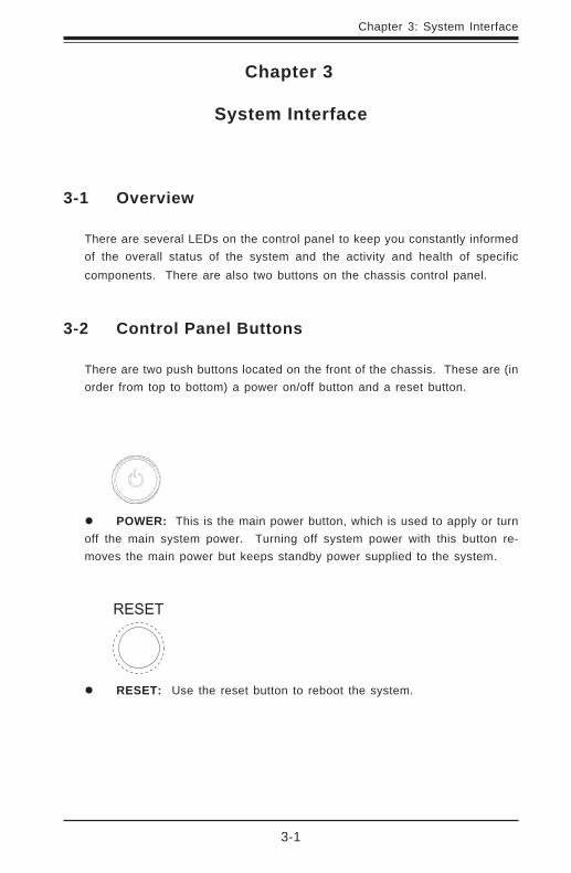
There are two push buttons located on the front of the chassis. These are (inorder from top to bottom) a power on/off button and a reset button.
POWER: This is the main power button, which is used to apply or turnoff the main system power. Turning off system power with this button re-moves the main power but keeps standby power supplied to the system.
RESET: Use the reset button to reboot the system.
3-2
SUPERWORKSTATION 7034A-T/7034A-i Manual
3-3 Control Panel LEDs
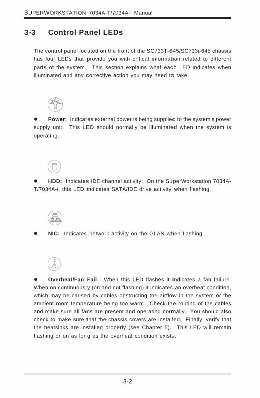
The control panel located on the front of the SC733T-645/SC733i-645 chassishas four LEDs that provide you with critical information related to differentparts of the system. This section explains what each LED indicates whenilluminated and any corrective action you may need to take.
Power: Indicates external power is being supplied to the system's powersupply unit. This LED should normally be illuminated when the system isoperating.
HDD: Indicates IDE channel activity. On the SuperWorkstation 7034A-T/7034A-i, this LED indicates SATA/IDE drive activity when flashing.
NIC: Indicates network activity on the GLAN when flashing.
Overheat/Fan Fail: When this LED flashes it indicates a fan failure.When on continuously (on and not flashing) it indicates an overheat condition,which may be caused by cables obstructing the airflow in the system or theambient room temperature being too warm. Check the routing of the cablesand make sure all fans are present and operating normally. You should alsocheck to make sure that the chassis covers are installed. Finally, verify thatthe heatsinks are installed properly (see Chapter 5). This LED will remainflashing or on as long as the overheat condition exists.
Chapter 3: System Interface
3-3
3-4 LAN (Ethernet) Port LEDs
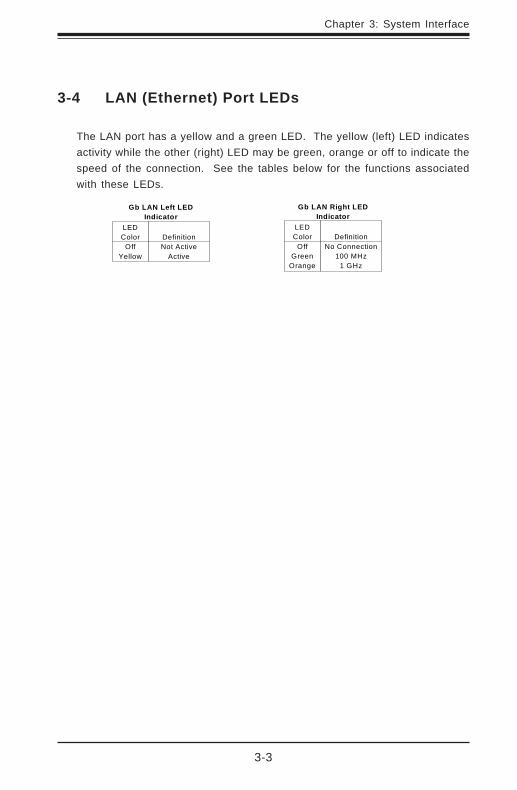
The LAN port has a yellow and a green LED. The yellow (left) LED indicatesactivity while the other (right) LED may be green, orange or off to indicate thespeed of the connection. See the tables below for the functions associatedwith these LEDs.
LEDColor
OffGreen
Orange
DefinitionNo Connection
100 MHz1 GHz
Gb LAN Right LEDIndicator
LEDColor
OffYellow
DefinitionNot Active
Active
Gb LAN Left LEDIndicator

3-4
SUPERWORKSTATION 7034A-T/7034A-i Manual
Notes

Chapter 4: System Safety
4-1
Chapter 4
System Safety
4-1 Electrical Safety Precautions
!
Basic electrical safety precautions should be followed to protectyourself from harm and the SuperWorkstation 7034A-T/7034A-i from damage:
Be aware of the locations of the power on/off switch on thechassis as well as the room's emergency power-off switch,disconnection switch or electrical outlet. If an electrical accidentoccurs, you can then quickly remove power from the system.
Do not work alone when working with high voltage components.
Power should always be disconnected from the system whenremoving or installing main system components, such as theserverboard, memory modules and the CD-ROM and floppy drives.When disconnecting power, you should first power down the systemwith the operating system and then unplug the power cords of all thepower supply units in the system.
When working around exposed electrical circuits, another personwho is familiar with the power-off controls should be nearby toswitch off the power if necessary.
Use only one hand when working with powered-on electricalequipment. This is to avoid making a complete circuit, which willcause electrical shock. Use extreme caution when using metaltools, which can easily damage any electrical components or circuitboards they come into contact with.
Do not use mats designed to decrease electrostatic discharge asprotection from electrical shock. Instead, use rubber mats thathave been specifically designed as electrical insulators.
4-2
SUPERWORKSTATION 7034A-T/7034A-i Manual
4-2 General Safety Precautions
Follow these rules to ensure general safety:
Keep the area around the SuperWorkstation 7034A-T/7034A-i clean andfree of clutter.
The SuperWorkstation 7034A-T/7034A-i weighs approximately 40 lbs.When lifting the system, two people at either end should lift slowly withtheir feet spread out to distribute the weight. Always keep your backstraight and lift with your legs.
Place the chassis top/side cover and any system components thathave been removed away from the system or on a table so thatthey won't accidentally be stepped on.
While working on the system, do not wear loose clothing such asneckties and unbuttoned shirt sleeves, which can come into contactwith electrical circuits or be pulled into a cooling fan.
Remove any jewelry or metal objects from your body, which areexcellent metal conductors that can create short circuits and harmyou if they come into contact with printed circuit boards or areas
!
The power supply power cord must include a grounding plug and must beplugged into grounded electrical outlets.
Serverboard Battery: CAUTION - There is a danger of explosion ifthe onboard battery is installed backwards, which will reverse itspolarities. The positive side of the battery should be facing up andthe negative side should facing the serverboard. This battery mustbe replaced only with the same or an equivalent type recommendedby the manufacturer. Dispose of used batteries according to themanufacturer's instructions.
CD-ROM Laser: CAUTION - this server may have come equippedwith a CD-ROM drive. To prevent direct exposure to the laser beamand hazardous radiation exposure, do not open the enclosure oruse the unit in any unconventional way.

Chapter 4: System Safety
4-3
4-3 ESD Precautions
Electrostatic discharge (ESD) is generated by two objects withdifferent electrical charges coming into contact with each other. Anelectrical discharge is created to neutralize this difference, which candamage electronic components and printed circuit boards. Thefollowing measures are generally sufficient to neutralize thisdifference before contact is made to protect your equipment from ESD:
Use a grounded wrist strap designed to prevent static discharge.
Keep all components and printed circuit boards (PCBs) in theirantistatic bags until ready for use.
Touch a grounded metal object before removing the board from theantistatic bag.
Do not let components or PCBs come into contact with yourclothing, which may retain a charge even if you are wearing a wriststrap.
Handle a board by its edges only; do not touch its components,peripheral chips, memory modules or contacts.
When handling chips or modules, avoid touching their pins.
Put the serverboard and peripherals back into their antistatic bagswhen not in use.
!
where power is present.
After accessing the inside of the system, close the system back upand (if rackmounted) secure it to the rack unit with the retentionscrews after ensuring that all connections have been made.
4-4
SUPERWORKSTATION 7034A-T/7034A-i Manual
4-4 Operating Precautions
Care must be taken to assure that all chassis covers are in place whenthe 7034A-T/7034A-i is operating to ensure proper cooling. Out ofwarranty damage to the 7034A-T/7034A-i system can occur if this practiceis not strictly followed.
!
For grounding purposes, make sure your computer chassisprovides excellent conductivity between the power supply, the case,the mounting fasteners and the serverboard.

Chapter 5: Advanced Serverboard Setup
5-1
Chapter 5
Advanced Serverboard Setup
This chapter covers the steps required to install processors and heatsinks to theX6DAL-TG/X6DAL-G serverboard, connect the data and power cables and installadd-on cards. All serverboard jumpers and connections are described and alayout and quick reference chart are included in this chapter. Remember to closethe chassis completely when you have finished working on the serverboard toprotect and cool the system sufficiently.
5-1 Handling the Serverboard
Static electrical discharge can damage electronic components. To preventdamage to printed circuit boards, it is important to handle them very care-fully (see Chapter 4). Also note that the size and weight of the serverboardcan cause it to bend if handled improperly, which may result in damage. Toprevent the serverboard from bending, keep one hand under the center ofthe board to support it when handling. The following measures are gener-ally sufficient to protect your equipment from static discharge.
Precautions
• Use a grounded wrist strap designed to prevent static discharge.• Touch a grounded metal object before removing any board from its anti-
static bag.• Handle a board by its edges only; do not touch its components, periph-
eral chips, memory modules or gold contacts.• When handling chips or modules, avoid touching their pins.• Put the serverboard, add-on cards and peripherals back into their anti-
static bags when not in use.
Unpacking
The serverboard is shipped in antistatic packaging to avoid static damage.When unpacking the board, make sure the person handling it is static pro-tected.
5-2
SUPERWORKSTATION 7034A-T/7034A-i Manual
!
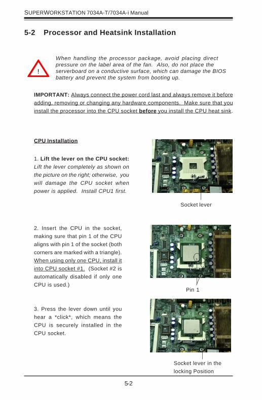
5-2 Processor and Heatsink Installation
When handling the processor package, avoid placing directpressure on the label area of the fan. Also, do not place theserverboard on a conductive surface, which can damage the BIOSbattery and prevent the system from booting up.
Socket lever
CPU Installation
1. Lift the lever on the CPU socket:Lift the lever completely as shown onthe picture on the right; otherwise, youwill damage the CPU socket whenpower is applied. Install CPU1 first.
IMPORTANT: Always connect the power cord last and always remove it beforeadding, removing or changing any hardware components. Make sure that youinstall the processor into the CPU socket before you install the CPU heat sink.
Pin 1
2. Insert the CPU in the socket,making sure that pin 1 of the CPUaligns with pin 1 of the socket (bothcorners are marked with a triangle).When using only one CPU, install itinto CPU socket #1. (Socket #2 isautomatically disabled if only oneCPU is used.)
3. Press the lever down until youhear a *click*, which means theCPU is securely installed in theCPU socket.
Socket lever in thelocking Position

Chapter 5: Advanced Serverboard Setup
5-3
Heatsink Installation*
1. Do not apply any thermal com-pound to the heatsink or the CPUdie; the required amount has al-ready been applied.
2. Place the heatsink on top ofthe CPU so that the four mountingholes are aligned with those on theretention mechanism.
3. Screw in two diagonal screws (iethe #1 and the #2 screws) until justsnug (-do not fully tighten thescrews to avoid possible damage tothe CPU.)
4. Finish the installation by fullytightening all four screws.
Figure 5-1. 604-pin PGA Socket: Empty and with Processor Installed
Warning! Make sure you lift the lever completely wheninstalling the CPU. If the lever is only partly raised, damageto the socket or CPU may result.
!
Lever
With processor installed
Triangle (pin 1)
Empty socket
Triangle locating pin 1
Screw #1
Screw #2
*Heatsink package is optional.*Fan speed is controlled by a setting in BIOS (see page 7-19).

5-4
SUPERWORKSTATION 7034A-T/7034A-i Manual
IMPORTANT: Removal of the heatsink or the CPU is not recom-mended. However, if you do need to remove the heatsink, pleasefollow the instructions below to prevent damaging the CPU or theCPU socket.
1. Unscrew and remove the heatsinkscrews from the serverboard in the se-quence as show in the picture on the right.
2. Hold the heatsink and gently wiggle itback and forth to loosen it from the CPU.(Do not use excessive force when loosen-ing the heatsink!!)
3. Once the heatsink has been loosenedfrom the CPU, remove the heatsink fromthe CPU socket.
4. Clean the surface of the CPU and theheatsink to get rid of the old thermalgrease. Reapply the proper amount ofthermal grease on the surface before youre-install the heatsink to the CPU.
!
Removing the Heatsink/CPU
Screw #1
Screw #2
Chapter 5: Advanced Serverboard Setup
5-5
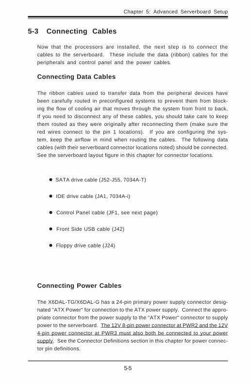
5-3 Connecting Cables
Now that the processors are installed, the next step is to connect thecables to the serverboard. These include the data (ribbon) cables for theperipherals and control panel and the power cables.
Connecting Data Cables
The ribbon cables used to transfer data from the peripheral devices havebeen carefully routed in preconfigured systems to prevent them from block-ing the flow of cooling air that moves through the system from front to back.If you need to disconnect any of these cables, you should take care to keepthem routed as they were originally after reconnecting them (make sure thered wires connect to the pin 1 locations). If you are configuring the sys-tem, keep the airflow in mind when routing the cables. The following datacables (with their serverboard connector locations noted) should be connected.See the serverboard layout figure in this chapter for connector locations.
SATA drive cable (J52-J55, 7034A-T)
IDE drive cable (JA1, 7034A-i)
Control Panel cable (JF1, see next page)
Front Side USB cable (J42)
Floppy drive cable (J24)
Connecting Power Cables
The X6DAL-TG/X6DAL-G has a 24-pin primary power supply connector desig-nated "ATX Power" for connection to the ATX power supply. Connect the appro-priate connector from the power supply to the "ATX Power" connector to supplypower to the serverboard. The 12V 8-pin power connector at PWR2 and the 12V4-pin power connector at PWR3 must also both be connected to your powersupply. See the Connector Definitions section in this chapter for power connec-tor pin definitions.

5-6
SUPERWORKSTATION 7034A-T/7034A-i Manual
Figure 5-2. JF1 Header Pins
Connecting the Control Panel
JF1 contains header pins for various front control panel connectors. SeeFigure 5-2 for the pin locations of the various front control panel buttons andLED indicators. Please note that even and odd numbered pins are onopposite sides of each header.
All JF1 wires have been bundled into single ribbon cable to simplify theirconnection. Make sure the red wire plugs into pin 1 as marked on theboard. The other end connects to the Control Panel printed circuit board,located just behind the system status LEDs in the chassis.
See the Connector Definitions section in this chapter for details and pindescriptions of JF1.
Power Button
Overheat LED
1
NIC1 LED
Reset Button
2
Power Fail LED
HDD LED
Power LED
Reset
Pwr
Vcc
Vcc
Vcc
Vcc
Ground
Ground
1920
Vcc
X
Ground NMI
X
X X

Chapter 5: Advanced Serverboard Setup
5-7
5-4 I/O Ports
The I/O ports are color coded in conformance with the PC 99 specification. SeeFigure 5-3 below for the colors and locations of the various I/O ports.
Figure 5-3. Rear Panel I/O Ports
5-5 Installing Memory
Note: Check the Supermicro web site for recommended memory modules:
http://www.supermicro.com/TECHSUPPORT/FAQs/Memory_vendors.htm
CAUTIONExercise extreme care when installing or removing DIMM
modules to prevent any possible damage. Also note that thememory is interleaved to improve performance (see step 1).
DIMM Installation (See Figures 5-4 and 5-5)
1. Insert the desired number of DIMMs into the memory slots, starting withBank #1A. The memory scheme is interleaved so you must install twomodules at a time, beginning with DIMM #1A, then DIMM #1B, and so on.
2. Insert each DIMM module vertically into its slot. Pay attention to thenotch along the bottom of the module to prevent inserting the DIMMmodule incorrectly.
3. Gently press down on the DIMM module until it snaps into place in theslot. Repeat for all modules (see step 1 above).
COM2 Port
AudioOut
Line-In
Mic
5-8
SUPERWORKSTATION 7034A-T/7034A-i Manual
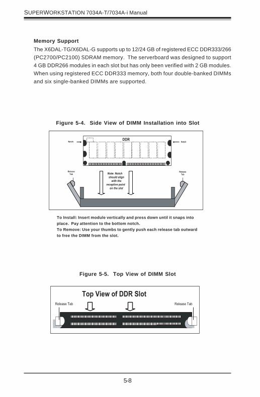
Figure 5-5. Top View of DIMM Slot
Figure 5-4. Side View of DIMM Installation into Slot
To Install: Insert module vertically and press down until it snaps intoplace. Pay attention to the bottom notch.To Remove: Use your thumbs to gently push each release tab outwardto free the DIMM from the slot.
Memory SupportThe X6DAL-TG/X6DAL-G supports up to 12/24 GB of registered ECC DDR333/266(PC2700/PC2100) SDRAM memory. The serverboard was designed to support4 GB DDR266 modules in each slot but has only been verified with 2 GB modules.When using registered ECC DDR333 memory, both four double-banked DIMMsand six single-banked DIMMs are supported.

Chapter 5: Advanced Serverboard Setup
5-9
5-6 Adding PCI Cards
1. PCI slots:The X6DAL-TG/X6DAL-G has six PCI expansion slots, which includes onePCI-Express x16 slot, one PCI-Express x8 slot, two PCI-X 66 MHz slots andtwo 32-bit 33MHz PCI slots. The SC733T-645/SC733i-645 chassis allows allsix slots to be populated.
2. PCI card installation:Before installing a PCI add-on card, make sure you install it into a slot thatsupports the speed of the card (see step 1, above). Begin by removing thescrew from the I/O backpanel shield that corresponds to the slot you wish topopulate. Insert the PCI card into the correct slot on the serverboard,pushing down with your thumbs evenly on both sides of the card. Finish bysecuring the card to the chassis with the same screw you removed from theI/O shield. Follow this procedure when adding a card to other slots.

5-10
SUPERWORKSTATION 7034A-T/7034A-i Manual
Figure 5-6. SUPER X6DAL-TG/X6DAL-G Layout*(not drawn to scale)
5-7 Serverboard Details
*Notes:
Jumpers not noted are for test purposes only.
" " indicates the location of Pin 1.
SATA controllers and connections do not apply to the X6DAL-G.
KB
/M
ou
se
DIMM 3A
DIMM 3B
DIMM 2A
DIMM 2B
DIMM 1A
DIMM 1B
Tumwater
(North Bridge)
Marvell
IDE
#1
IDE
#2
US
B0
/1
COM2
COM1
8-pinP W 2
ATX PWRJPFForcePW-On
MicJ 2 6
AudioEnable
SI/
O
PCI-E6 (x16)
PCI-X 3 (66 MHz)
PCI-X2 (66 MHz)
Battery
WOR JPS1
FAN
1
LAN1
Aux in
CDin
PCI-4 (33MHz)
J 1 3 J 1 5
JPL1
PCI-E1 (X8)
Floppy
PW LED/KL
SATA
2
ChassisIntrusion
HanceRapids
USB2/3 JF1
JBT1
JWD
J 6Dn:Line_InUp:Line_Out
J 4 1
J35
JSL
ED
SATA
LE
D
SATA
I2 C
(*X
6DA
L-T
G)
WatchDogLAN1 Enable
Fan5Fan6
JWOL
JF2 SpkrCL CMOS
Fan
4F
P C
tlr
Fan3
Fan2
CPU2
CPU1
SMB data toPCIEn.SMBCLKtoPCI En.
CN
1
AlMRset
J 2 7J 7P W
FaultSMB PW
J 2
J 4
J 5
PCI-5 (33MHz)
J 3
P W 1
PW
3
J 4 3
LANCTRL
BIOS
Printer Spkr SATA
0
SATA
3
SATA
1JL1
SATACTRL
Marvell SATAEnable
H-S
ATA
0
H-S
ATA
1
JS0
JS1
DS1DS3
DS6
DS2DS5
DS
7
DS
8
DS9
Chapter 5: Advanced Serverboard Setup
5-11
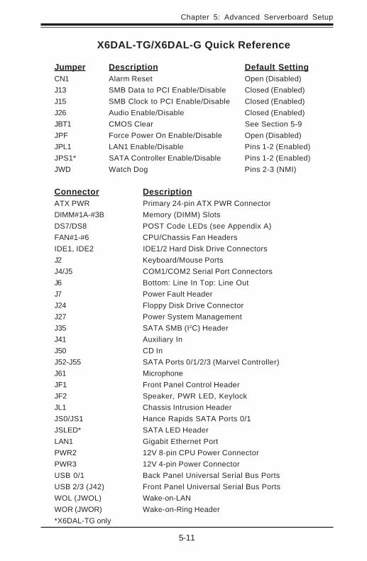
X6DAL-TG/X6DAL-G Quick Reference
Jumper Description Default SettingCN1 Alarm Reset Open (Disabled)J13 SMB Data to PCI Enable/Disable Closed (Enabled)J15 SMB Clock to PCI Enable/Disable Closed (Enabled)J26 Audio Enable/Disable Closed (Enabled)JBT1 CMOS Clear See Section 5-9JPF Force Power On Enable/Disable Open (Disabled)JPL1 LAN1 Enable/Disable Pins 1-2 (Enabled)JPS1* SATA Controller Enable/Disable Pins 1-2 (Enabled)JWD Watch Dog Pins 2-3 (NMI)
Connector DescriptionATX PWR Primary 24-pin ATX PWR ConnectorDIMM#1A-#3B Memory (DIMM) SlotsDS7/DS8 POST Code LEDs (see Appendix A)FAN#1-#6 CPU/Chassis Fan HeadersIDE1, IDE2 IDE1/2 Hard Disk Drive ConnectorsJ2 Keyboard/Mouse PortsJ4/J5 COM1/COM2 Serial Port ConnectorsJ6 Bottom: Line In Top: Line OutJ7 Power Fault HeaderJ24 Floppy Disk Drive ConnectorJ27 Power System ManagementJ35 SATA SMB (I2C) HeaderJ41 Auxiliary InJ50 CD InJ52-J55 SATA Ports 0/1/2/3 (Marvel Controller)J61 MicrophoneJF1 Front Panel Control HeaderJF2 Speaker, PWR LED, KeylockJL1 Chassis Intrusion HeaderJS0/JS1 Hance Rapids SATA Ports 0/1JSLED* SATA LED HeaderLAN1 Gigabit Ethernet PortPWR2 12V 8-pin CPU Power ConnectorPWR3 12V 4-pin Power ConnectorUSB 0/1 Back Panel Universal Serial Bus PortsUSB 2/3 (J42) Front Panel Universal Serial Bus PortsWOL (JWOL) Wake-on-LANWOR (JWOR) Wake-on-Ring Header*X6DAL-TG only

5-12
SUPERWORKSTATION 7034A-T/7034A-i Manual
5-8 Connector Definitions
Power LED
The Power LED connection is lo-cated on pins 15 and 16 of JF1. Re-fer to the table on the right for pindefinitions.
ATX Power Connector
The X6DAL-TG/X6DAL-G includes a24-pin main power supply connector(PW1) and a 4-pin CPU PWR con-nector (PWR3). Both connectionsare required. These power connec-tors meet the SSI EPS 12V specifi-cation. See the table on the right forpin def in i t ions. For CPU PWR(PW2), please refer to the item listedbelow.
PinNumber
1516
DefinitionVcc
Control
PWR_LED Pin Definitions(JF1)
ATX Power Supply 24-pin ConnectorPin Definitions (PW1)
Pin Number Definition 13 +3.3V 14 -12V 15 COM 16 PS_ON# 17 COM 18 COM 19 COM 20 Res(NC) 21 +5V 22 +5V 23 +5V 24 COM
Pin Number Definition 1 +3.3V 2 +3.3V 3 COM 4 +5V
5 COM 6 +5V
7 COM 8 PWR_OK
9 5VSB 10 +12V 11 +12V 12 +3.3V
Pins #1 & 23 & 4
DefinitionGround+12 V
+12V 4-pin Connector(PWR3)
Required
ConnectionProcessor PowerConnector
In addition to the Primary ATX powerconnector (above), the 12v 8-pin pro-cessor power connector at PWR2must also be connected to yourpower supply. See the table on theright for pin definitions.
Pins1 thru 45 thru 8
DefinitionGround
+12v
CPU 8-pin PWRConnector (PWR2)
Required
Connection
NMI Button
The non-maskable interrupt buttonheader is located on pins 19 and 20of JF1. Refer to the table on the rightfor pin definitions.
PinNumber
1920
DefinitionControlGround
NMI Button PinDefinitions (JF1)
Chapter 5: Advanced Serverboard Setup
5-13
Overheat/Fan Fail LED
Connect an LED to the OH connec-tion on pins 7 and 8 of JF1 to provideadvanced warning of chassis over-heating. The LED will blink as longas an overheat condition exists.Refer to the table on the right for pindefinitions.
NIC LED
The NIC (Network Interface Con-trol ler) LED connection for theGLAN port is located on pins 11and 12 of JF1. Attach the NIC LEDcable to display network activity.Refer to the table on the right forpin definitions.
NIC1 LED PinDefinitions
(JF1)Pin
Number9/11
10/12
DefinitionVcc
GND
Overheat (OH) LEDPin Definitions
(JF1)Pin
Number78
DefinitionVcc
GND
Power Fail LED PinDefinitions
(JF1)Pin
Number56
DefinitionVcc
GND
HDD LED
The HDD LED connection is locatedon pins 13 and 14 of JF1. Attach thehard drive LED cable to these pins todisplay hard disk drive activity. Re-fer to the table on the right for pindefinitions.
HDD LED PinDefinitions
(JF1)Pin
Number1314
DefinitionVcc
HD Active
Power Fail LED
The Power Fail LED connection islocated on pins 5 and 6 of JF1. Referto the table on the right for pin defi-nitions.
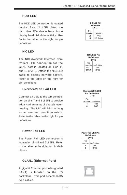
GLAN1 (Ethernet Port)
A gigabit Ethernet port (designatedLAN1) is located on the I /Obackplane. This port accepts RJ45type cables.
5-14
SUPERWORKSTATION 7034A-T/7034A-i Manual
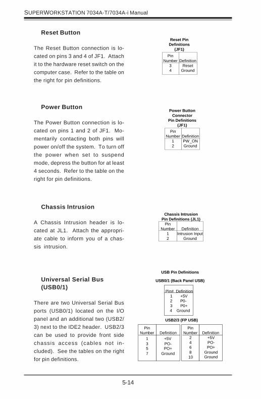
Power Button
The Power Button connection is lo-cated on pins 1 and 2 of JF1. Mo-mentarily contacting both pins willpower on/off the system. To turn offthe power when set to suspendmode, depress the button for at least4 seconds. Refer to the table on theright for pin definitions.
PinNumber
12
DefinitionPW_ONGround
Power ButtonConnector
Pin Definitions(JF1)
Universal Serial Bus(USB0/1)
There are two Universal Serial Busports (USB0/1) located on the I/Opanel and an additional two (USB2/3) next to the IDE2 header. USB2/3can be used to provide front sidechassis access (cables not in-cluded). See the tables on the rightfor pin definitions.
Reset Button
The Reset Button connection is lo-cated on pins 3 and 4 of JF1. Attachit to the hardware reset switch on thecomputer case. Refer to the table onthe right for pin definitions.
Chassis Intrusion
A Chassis Intrusion header is lo-cated at JL1. Attach the appropri-ate cable to inform you of a chas-sis intrusion.
PinNumber
34
DefinitionReset
Ground
Reset PinDefinitions
(JF1)
PinNumber
12
DefinitionIntrusion Input
Ground
Chassis IntrusionPin Definitions (JL1)
Pin# Definition 1 +5V2 P0- 3 P0+
4 Ground
PinNumber
246810
Definition+5VPO-PO+
GroundGround
PinNumber
1357
Definition+5VPO-PO+
Ground
USB Pin Definitions
USB2/3 (FP USB)
USB0/1 (Back Panel USB)
Chapter 5: Advanced Serverboard Setup
5-15
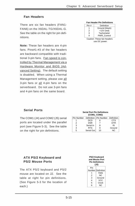
ATX PS/2 Keyboard andPS/2 Mouse Ports
The ATX PS/2 keyboard and PS/2mouse are located on J2. See thetable at right for pin definitions.(See Figure 5-3 for the location ofeach.)
PS/2 Keyboardand Mouse PortPin Definitions
(J2)Pin
Number123456
DefinitionDataNC
GroundVCCClockNC
Serial Ports
The COM1 (J4) and COM2 (J5) serialports are located under the parallelport (see Figure 5-3). See the tableon the right for pin definitions.
Fan Headers
There are six fan headers (FAN1-FAN6) on the X6DAL-TG/X6DAL-G.See the table on the right for pin defi-nitions.
Note: These fan headers are 4-pinfans. Pins#1-#3 of the fan headersare backward compatible with tradi-tional 3-pin fans. Fan speed is con-trolled by Thermal Management via aHardware Monitor and BIOS (Ad-vanced Setting). The default settingis disabled. When using a ThermalManagement setting, please use all3-pin fans or all 4-pin fans on theserverboard. Do not use 3-pin fansand 4-pin fans on the same board.
Fan Header Pin DefinitionsPin #
1234
DefinitionGround (black)
+12V (red)Tachometer
PWR_ControlCaution: These fan headers
use DC power.
Serial Port Pin Definitions(COM1, COM2)
Pin Number Definition 1 DCD 2 DSR 3 Serial In 4 RTS 5 Serial Out
Pin Number Definition 6 CTS 7 DTR 8 RI 9 Ground 10 NC
5-16
SUPERWORKSTATION 7034A-T/7034A-i Manual
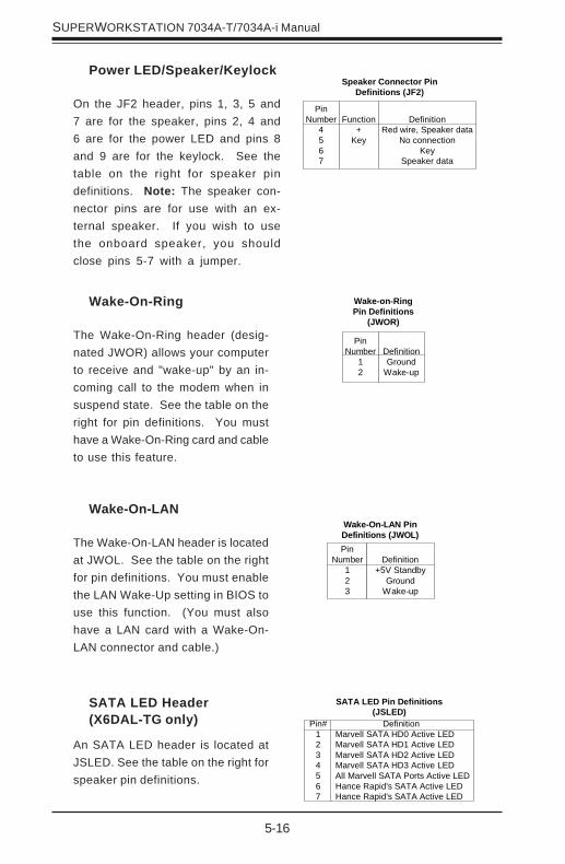
Power LED/Speaker/Keylock
On the JF2 header, pins 1, 3, 5 and7 are for the speaker, pins 2, 4 and6 are for the power LED and pins 8and 9 are for the keylock. See thetable on the right for speaker pindefinitions. Note: The speaker con-nector pins are for use with an ex-ternal speaker. If you wish to usethe onboard speaker, you shouldclose pins 5-7 with a jumper.
Speaker Connector PinDefinitions (JF2)
PinNumber
4567
Function+
Key
DefinitionRed wire, Speaker data
No connectionKey
Speaker data
Wake-On-Ring
The Wake-On-Ring header (desig-nated JWOR) allows your computerto receive and "wake-up" by an in-coming call to the modem when insuspend state. See the table on theright for pin definitions. You musthave a Wake-On-Ring card and cableto use this feature.
Wake-on-RingPin Definitions
(JWOR)
PinNumber
12
DefinitionGround
Wake-up
Wake-On-LAN
The Wake-On-LAN header is locatedat JWOL. See the table on the rightfor pin definitions. You must enablethe LAN Wake-Up setting in BIOS touse this function. (You must alsohave a LAN card with a Wake-On-LAN connector and cable.)
PinNumber
123
Definition+5V Standby
GroundWake-up
Wake-On-LAN PinDefinitions (JWOL)
SATA LED Header(X6DAL-TG only)
An SATA LED header is located atJSLED. See the table on the right forspeaker pin definitions.
SATA LED Pin Definitions(JSLED)
Pin#1234567
Definition Marvell SATA HD0 Active LED Marvell SATA HD1 Active LED Marvell SATA HD2 Active LED Marvell SATA HD3 Active LED All Marvell SATA Ports Active LED Hance Rapid's SATA Active LED Hance Rapid's SATA Active LED

Chapter 5: Advanced Serverboard Setup
5-17
Power Fault
Connect a cable from your powersupply to the Power Fail header (J7)to provide warning of power supplyfailure. This warning signal ispassed through the PWR_LED pin toindicate of a power failure on thechassis. See the table on the rightfor pin definitions.
Power FailPin Definitions (J7)
PinNumber
1234
DefinitionP/S 1 Fail SignalP/S 2 Fail SignalP/S 3 Fail SignalReset (from MB)
Note: This feature is only available when
using redundant Supermicro power supplies.
SMB Power (I2 C)Connector
An I2C connector (J27), located be-tween the Alarm Reset header andthe PWR Fail header monitors thestatus of the PWR supply, the fansand the system temperature.
SMB PWRPin Definitions (J27)
Pin #12345
DefinitionClock
SMB DataN/AN/AN/A
CD-In Headers
The 4-pin CD header on theserverboard (J50) allows you to usethe onboard sound for audio CD play-back. Connect the audio cable fromyour CD drive to the header. See thetable at right for pin definitions.
Audio CD Header Pin Definitions(J50)
PinNumber
1234
Definition
Right Stereo SignalGround
GroundLeft Stereo Signal
Audio CD Header Pin Definitions(J50)
PinNumber
1234
Definition
Left Stereo SignalGroundGround
Right Stereo Signal
SATA SMB (I2C) (X6DAL-TG only)
An SATA System Management Busheader is located at J35. Connectthe appropriate cable here to utilizeSATA SMB on your system.
SATA SMB (J35)Pin Definitions
PinNumber
123
DefinitionData
GroundClock

5-18
SUPERWORKSTATION 7034A-T/7034A-i Manual
5-9 Jumper Settings
Explanation ofJumpers
To modify the operation of theserverboard, jumpers can beused to choose betweenopt ional sett ings. Jumperscreate shorts between two pinsto change the function of theconnector. Pin 1 is identifiedwith a square solder pad onthe printed circuit board. Seethe serverboard layout pagesfor jumper locations.Note: On two pin jumpers,"Closed" means the jumper ison and "Open" means thejumper is off the pins.
ConnectorPins
JumperCap
Setting
Pin 1-2 short
3 2 1
3 2 1
CMOS Clear
JBT1 is used to clear CMOS (which will also clear any passwords). Instead ofpins, this jumper consists of contact pads to prevent accidentally clearing thecontents of CMOS.To clear CMOS,1) First unplug the power cord(s)2) With the power disconnected, short the CMOS pads with a metal object suchas a small screwdriver3) Remove the screwdriver (or shorting device)4) Reconnect the power cord(s) and power on the system.Note: Do not use the PW_ON connector to clear CMOS.
Serial ATA Enable/Disable(X6DAL-TG only)
Jumper JPS1 allows you to enable ordisable the onboard SATA (Marvell)controller ports. See the table on theright for jumper settings. The defaultsetting is enabled.
JumperPositionPins 1-2Pins 2-3
DefinitionEnabledDisabled
SATA Enable/DisableJumper Settings
(JPS1)
Chapter 5: Advanced Serverboard Setup
5-19
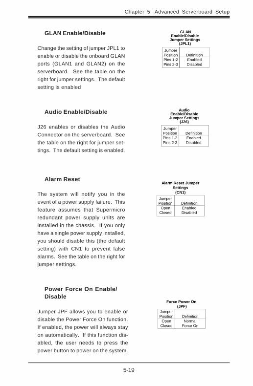
GLAN Enable/Disable
Change the setting of jumper JPL1 toenable or disable the onboard GLANports (GLAN1 and GLAN2) on theserverboard. See the table on theright for jumper settings. The defaultsetting is enabled
JumperPositionPins 1-2Pins 2-3
DefinitionEnabledDisabled
GLANEnable/Disable
Jumper Settings(JPL1)
Audio Enable/Disable
J26 enables or disables the AudioConnector on the serverboard. Seethe table on the right for jumper set-tings. The default setting is enabled.
JumperPositionPins 1-2Pins 2-3
DefinitionEnabledDisabled
AudioEnable/Disable
Jumper Settings(J26)
Alarm Reset
The system will notify you in theevent of a power supply failure. Thisfeature assumes that Supermicroredundant power supply units areinstalled in the chassis. If you onlyhave a single power supply installed,you should disable this (the defaultsetting) with CN1 to prevent falsealarms. See the table on the right forjumper settings.
JumperPosition
OpenClosed
DefinitionEnabledDisabled
Alarm Reset JumperSettings
(CN1)
Power Force On Enable/Disable
Jumper JPF allows you to enable ordisable the Power Force On function.If enabled, the power will always stayon automatically. If this function dis-abled, the user needs to press thepower button to power on the system.
JumperPosition
OpenClosed
DefinitionNormal
Force On
Force Power On (JPF)

5-20
SUPERWORKSTATION 7034A-T/7034A-i Manual
Blue: Line In (surround
sound L/R)
Green: Line Out
(front L/R)
Pink: MIC In (center/
subwoofer)
AC'97 Audio Enable/Disable
AC'97 provides high quality onboard au-dio. The X6DAL-TG/X6DAL-G features6-channel sound for front L&R, rear L&R,center and subwoofer speakers. Thisfeature is activated with the Advancedsoftware on the CD-ROM included withyour serverboard. The Line In, Line Outand MIC jacks (see at right) may thenbe used. Activate AC 97 with the "AC97 Audio" setting in the AdvancedChipset Features section of BIOS.
Watch Dog Enable/Disable
JWD enables the Watch Dog func-tion. Watch Dog is a system moni-tor that can reboot the system whena software application is "hung up".Pins 1-2 will cause WD to reset thesystem if an application is hung up.Pins 2-3 wi l l generate a non-maskable interrupt signal for the ap-plication that is hung up. See thetable on the right for jumper settings.Watch Dog can also be enabled viaBIOS.
Note: When enabled, the user needsto write his own application softwarein order to disable the Watch DogTimer.
JumperPositionPins 1-2Pins 2-3
Open
DefinitionWD to ResetWD to NMIDisabled
Watch DogJumper Settings (JWD)
Chapter 5: Advanced Serverboard Setup
5-21
5-10 Onboard Indicators
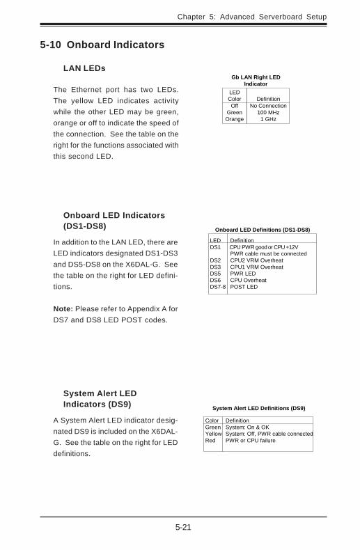
LAN LEDs
The Ethernet port has two LEDs.The yellow LED indicates activitywhile the other LED may be green,orange or off to indicate the speed ofthe connection. See the table on theright for the functions associated withthis second LED.
LEDColorOff
GreenOrange
DefinitionNo Connection
100 MHz1 GHz
Gb LAN Right LEDIndicator
Onboard LED Indicators(DS1-DS8)
In addition to the LAN LED, there areLED indicators designated DS1-DS3and DS5-DS8 on the X6DAL-G. Seethe table on the right for LED defini-tions.
Note: Please refer to Appendix A forDS7 and DS8 LED POST codes.
Onboard LED Definitions (DS1-DS8)
LED DS1
DS2 DS3 DS5 DS6 DS7-8
Definition CPU PWR good or CPU +12V PWR cable must be connected CPU2 VRM Overheat CPU1 VRM Overheat PWR LED CPU Overheat POST LED
System Alert LEDIndicators (DS9)
A System Alert LED indicator desig-nated DS9 is included on the X6DAL-G. See the table on the right for LEDdefinitions.
System Alert LED Definitions (DS9)
Color Green Yellow Red
Definition System: On & OK System: Off, PWR cable connected PWR or CPU failure
5-22
SUPERWORKSTATION 7034A-T/7034A-i Manual
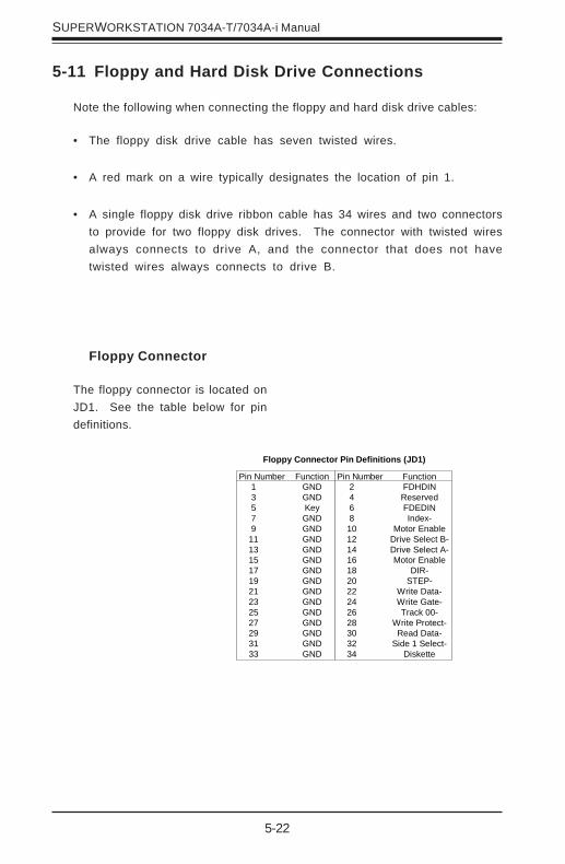
Pin Number Function 1 GND 3 GND 5 Key 7 GND 9 GND 11 GND 13 GND 15 GND 17 GND 19 GND 21 GND 23 GND 25 GND 27 GND 29 GND 31 GND 33 GND
Pin Number Function 2 FDHDIN 4 Reserved 6 FDEDIN 8 Index- 10 Motor Enable 12 Drive Select B- 14 Drive Select A- 16 Motor Enable 18 DIR- 20 STEP- 22 Write Data- 24 Write Gate- 26 Track 00- 28 Write Protect- 30 Read Data- 32 Side 1 Select- 34 Diskette
Floppy Connector Pin Definitions (JD1)
Floppy Connector
The floppy connector is located onJD1. See the table below for pindefinitions.
5-11 Floppy and Hard Disk Drive Connections
Note the following when connecting the floppy and hard disk drive cables:
• The floppy disk drive cable has seven twisted wires.
• A red mark on a wire typically designates the location of pin 1.
• A single floppy disk drive ribbon cable has 34 wires and two connectorsto provide for two floppy disk drives. The connector with twisted wiresalways connects to drive A, and the connector that does not havetwisted wires always connects to drive B.
Chapter 5: Advanced Serverboard Setup
5-23
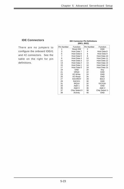
IDE Connectors
There are no jumpers toconfigure the onboard IDE#1and #2 connectors. See thetable on the right for pindefinitions.
Pin Number Function 1 Reset IDE 3 Host Data 7 5 Host Data 6 7 Host Data 5 9 Host Data 4 11 Host Data 3 13 Host Data 2 15 Host Data 1 17 Host Data 0 19 GND 21 DRQ3 23 I/O Write- 25 I/O Read- 27 IOCHRDY 29 DACK3- 31 IRQ14 33 Addr 1 35 Addr 0 37 Chip Select 0 39 Activity
Pin Number Function 2 GND 4 Host Data 8 6 Host Data 9 8 Host Data 10 10 Host Data 11 12 Host Data 12 14 Host Data 13 16 Host Data 14 18 Host Data 15 20 Key 22 GND 24 GND 26 GND 28 BALE 30 GND 32 IOCS16- 34 GND 36 Addr 2 38 Chip Select 1- 40 GND
IDE Connector Pin Definitions(IDE1, IDE2)

5-24
SUPERWORKSTATION 7034A-T/7034A-i Manual
Notes
Chapter 6: Advanced Chassis Setup
6-1
Chapter 6
Advanced Chassis Setup
This chapter covers the steps required to install components and perform simplemaintenance on the SC733T-645/SC733i-645 chassis. Following the componentinstallation steps in the order given will eliminate most common problems. Ifsome steps are unnecessary, skip ahead to the next step.
Tools RequiredThe only tool you will need is a Philips screwdriver.
6-1 Static-Sensitive Devices
Static electrical discharge can damage electronic components. To prevent dam-age to any printed circuit boards (PCBs), it is important to handle them verycarefully. The following measures are generally sufficient to protect your equip-ment from static discharge.
Precautions
• Use a grounded wrist strap designed to prevent static discharge.• Touch a grounded metal object before removing any board from its antistatic
bag.• Handle a board by its edges only; do not touch its components, peripheral
chips, memory modules or gold contacts.• When handling chips or modules, avoid touching their pins.• Put the serverboard, add-on cards and peripherals back into their antistatic
bags when not in use.• For grounding purposes, make sure your computer chassis provides excellent
conductivity between the power supply, the case, the mounting fasteners andthe serverboard.
Unpacking
The serverboard is shipped in antistatic packaging. When unpacking the board,make sure the person handling it is static protected.
6-2
SUPERWORKSTATION 7034A-T/7034A-i Manual
6-2 Front Control Panel
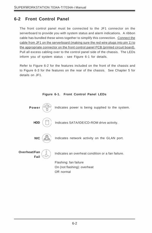
The front control panel must be connected to the JF1 connector on theserverboard to provide you with system status and alarm indications. A ribboncable has bundled these wires together to simplify this connection. Connect thecable from JF1 on the serverboard (making sure the red wire plugs into pin 1) tothe appropriate connector on the front control panel PCB (printed circuit board).Pull all excess cabling over to the control panel side of the chassis. The LEDsinform you of system status - see Figure 6-1 for details.
Refer to Figure 6-2 for the features included on the front of the chassis andto Figure 6-3 for the features on the rear of the chassis. See Chapter 5 fordetails on JF1.
Figure 6-1. Front Control Panel LEDs
Power
NIC
HDD
Overheat/FanFail
Indicates power is being supplied to the system.
Indicates network activity on the GLAN port.
Indicates SATA/IDE/CD-ROM drive activity.
Indicates an overheat condition or a fan failure.
Flashing: fan failureOn (not flashing): overheatOff: normal

Chapter 6: Advanced Chassis Setup
6-3
Figure 6-2. Chassis Front View
5.25" Drive Bays
System Reset
Main Power
System LEDs
Front Side USB
Floppy Drive Bay
Front Bezel Lock
(7034A-T only)
9-cm Fan Bay
(inside chassis)
7034A-T 7034A-i
6-4
SUPERWORKSTATION 7034A-T/7034A-i Manual
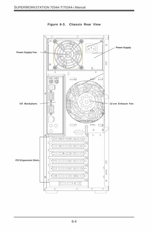
Figure 6-3. Chassis Rear View
Power Supply
PCI Expansion Slots
I/O Backplane 12-cm Exhaust Fan
Power Supply Fan
Chapter 6: Advanced Chassis Setup
6-5
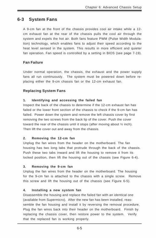
6-3 System Fans
A 9-cm fan at the front of the chassis provides cool air intake while a 12-cm exhaust fan at the rear of the chassis pulls the cool air through thesystem and expels the hot air. Both fans feature PWM (Pulse Width Modula-tion) technology, which enables fans to adjust their speed according to theheat level sensed in the system. This results in more efficient and quieterfan operation. Fan speed is controlled by a setting in BIOS (see page 7-19).
Fan Failure
Under normal operation, the chassis, the exhaust and the power supplyfans all run continuously. The system must be powered down before re-placing either the 9-cm chassis fan or the 12-cm exhaust fan.
Replacing System Fans
1. Identifying and accessing the failed fanInspect the back of the chassis to determine if the 12-cm exhaust fan hasfailed or the lower front section of the chassis to check if the 9-cm fan hasfailed. Power down the system and remove the left chassis cover by firstremoving the two screws from the back lip of the cover. Push the covertoward the rear of the chassis until it stops (after moving about ½ inch).Then lift the cover out and away from the chassis.
2. Removing the 12-cm fanUnplug the fan wires from the header on the motherboard. The fanhousing has two long tabs that protrude through the back of the chassis.Push these two tabs inward and lift the housing to remove it from itslocked position, then lift the housing out of the chassis (see Figure 6-4).
3. Removing the 9-cm fanUnplug the fan wires from the header on the motherboard. The housingfor the 9-cm fan is attached to the chassis with a single screw. Removethis screw and lift the housing out of the chassis (see Figure 6-5).
4. Installing a new system fanDisassemble the housing and replace the failed fan with an identical one(available from Supermicro). After the new fan has been installed, reas-semble the fan housing and install it by reversing the removal procedure.Plug the fan wires back into their header on the motherboard. Finish byreplacing the chassis cover, then restore power to the system. Verifythat the replaced fan is working properly.

6-6
SUPERWORKSTATION 7034A-T/7034A-i Manual
Figure 6-5. Removing the 9-cm Chassis Fan
Figure 6-4. Removing the 12-cm Exhaust Fan

Chapter 6: Advanced Chassis Setup
6-7
6-4 Drive Bay Installation
7034A-T: A swinging bezel covers the front of the chassis but does notneed to be removed to access the drives. To access the SATA drives,simply unlock the bezel and swing it open.
7034A-i: The bezel that covers the front of the chassis must be removed toaccess the drives. To remove the bezel, push on the three tabs on theinside left side lip of the front chassis cover. Then slightly swing out thesame (left) side of the cover - about ½ inch only. Remove by pushing onthe open side of the cover to remove it from the chassis (do not try toswing or pull it straight out after opening the left side.
Serial ATA Drives (7034A-T only)
After unlocking the Serial ATA (SATA) drive bay door, swing it open to accessthe SATA drives. The drive IDs are preconfigured as 0 through 3 in order frombottom to top.
Important!Use extreme caution when working around the SATAbackplane. Do not touch the backplane with any metalobjects and make sure no ribbon cables touch thebackplane or obstruct the airf low holes in the SATAbackplane. Regardless of how many SATA hard drivesare installed, all four SATA drive carriers must remain inthe drive bays to promote proper airflow.
!
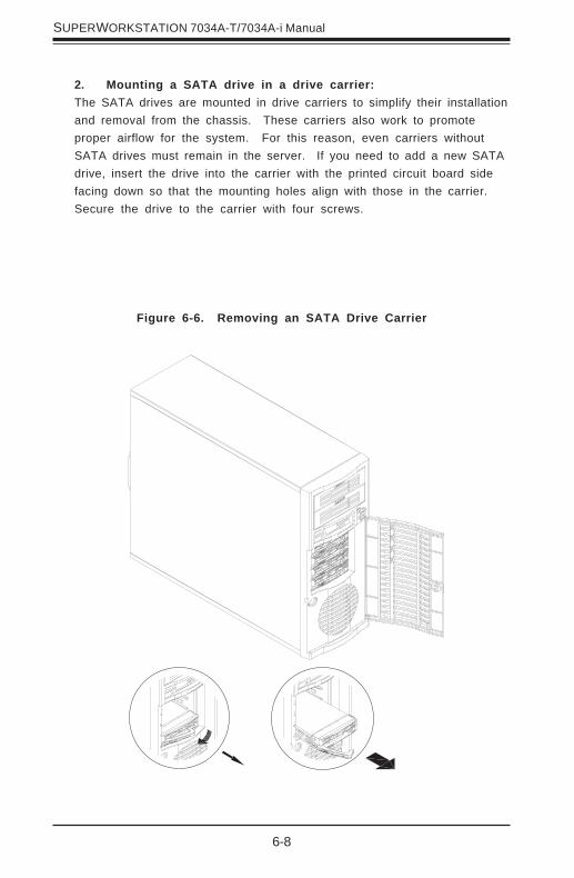
1. Installing/removing hot-plug SATA drives:The four SATA drive carriers are all easily accessible at the front of thechassis. The SATA drives are hot-swappable, meaning they can be removedand installed without powering down the system. To remove a drive carrier,first open the front bezel then push the release button located beside thedrive LEDs. Swing the colored handle fully out and use it to pull the unitstraight out (see Figure 6-6).
Note: Your operating system must have RAID support to enable the hot-plug capability of the SATA drives.
6-8
SUPERWORKSTATION 7034A-T/7034A-i Manual
Figure 6-6. Removing an SATA Drive Carrier
2. Mounting a SATA drive in a drive carrier:The SATA drives are mounted in drive carriers to simplify their installationand removal from the chassis. These carriers also work to promoteproper airflow for the system. For this reason, even carriers withoutSATA drives must remain in the server. If you need to add a new SATAdrive, insert the drive into the carrier with the printed circuit board sidefacing down so that the mounting holes align with those in the carrier.Secure the drive to the carrier with four screws.

Chapter 6: Advanced Chassis Setup
6-9
3. SATA backplane:All four SATA drives plug into the SATA backplane. There are twojumpers and two headers on the SATA backplane, as noted below. Aribbon cable from JA1 on the serverboard should be connected to the JP26connector on the SATA backplane. There are also two power connectors onthe backplane - both should be connected. See Figure 6-7 for thelocations of backplane connectors - the reverse side of the backplanehas four channel connectors that the SATA drives plug into wheninserted with a SATA drive carrier. You cannot cascade the SATAbackplane.
Figure 6-7. SATA733 Backplane
Power Connections SATA Channel Connections
Jumper Description SettingJP18 Buzzer Reset Alarm Reset HeaderJP25 OH Temperature Open: 45 degrees C
Pins 1-2: 50 degrees C (default)Pins 2-3: 55 degrees C
JP26 SATA Drive Activity Drive ActivityJP28 Fan Sense Pins 1-2: Enable
Pins 2-3: Disable (default)
6-10
SUPERWORKSTATION 7034A-T/7034A-i Manual
Figure 6-8. Adding a Component Without a Drive Carrier
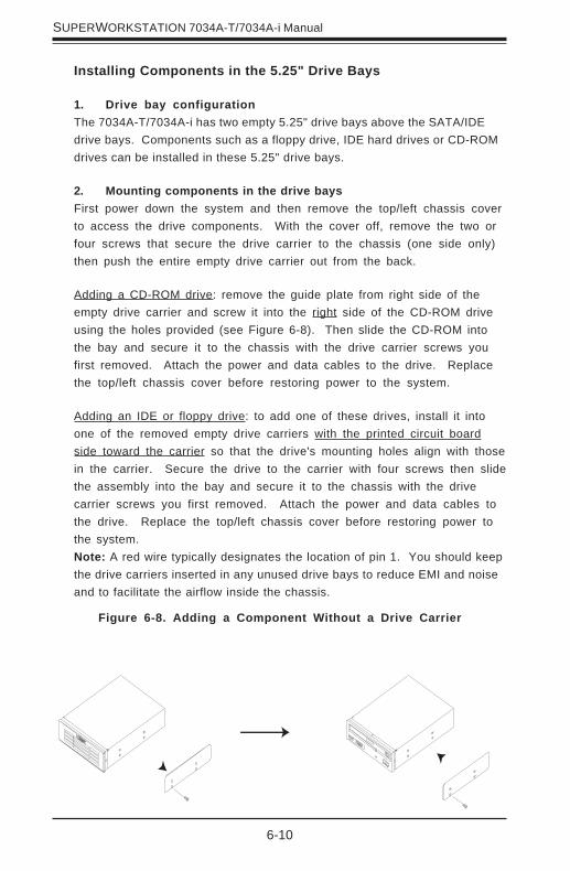
Installing Components in the 5.25" Drive Bays
1. Drive bay configurationThe 7034A-T/7034A-i has two empty 5.25" drive bays above the SATA/IDEdrive bays. Components such as a floppy drive, IDE hard drives or CD-ROMdrives can be installed in these 5.25" drive bays.
2. Mounting components in the drive baysFirst power down the system and then remove the top/left chassis coverto access the drive components. With the cover off, remove the two orfour screws that secure the drive carrier to the chassis (one side only)then push the entire empty drive carrier out from the back.
Adding a CD-ROM drive: remove the guide plate from right side of theempty drive carrier and screw it into the right side of the CD-ROM driveusing the holes provided (see Figure 6-8). Then slide the CD-ROM intothe bay and secure it to the chassis with the drive carrier screws youfirst removed. Attach the power and data cables to the drive. Replacethe top/left chassis cover before restoring power to the system.
Adding an IDE or floppy drive: to add one of these drives, install it intoone of the removed empty drive carriers with the printed circuit boardside toward the carrier so that the drive's mounting holes align with thosein the carrier. Secure the drive to the carrier with four screws then slidethe assembly into the bay and secure it to the chassis with the drivecarrier screws you first removed. Attach the power and data cables tothe drive. Replace the top/left chassis cover before restoring power tothe system.Note: A red wire typically designates the location of pin 1. You should keepthe drive carriers inserted in any unused drive bays to reduce EMI and noiseand to facilitate the airflow inside the chassis.

Chapter 6: Advanced Chassis Setup
6-11
6-5 Power Supply
The 7034A-T/7034A-i has a single 645W redundant cooling power supply (part#PWS-0060) that features noise-suppression technology for silent operation. Thepower supply has the capability to automatically sense and operate at 100 - 240VAC. This power supply also has PFC (Power Factor Correction) built in.
Power Supply Failure
If the power supply unit fails, the system will shut down and you will need toreplace the power supply unit. Replacement units can be ordered directly fromSupermicro (see contact infomation in Chapter 1).
Replacing the Power Supply
1. Accessing the power supply:After powering down the system, you’ll need to remove the left chassiscover to access the power supply for removal.
2. Removing the power supply:First, unplug the power cord from the power supply. Then remove thepower supply connectors going to the serverboard (ATX PWR, PWR2 andPWR3). Finally, remove the screws that secure the unit to the mountingbrackets in the chassis and then pull the unit completely out.
3. Installing a new power supply module:Replace the failed unit with another unit having the exact same partnumber. Gently but firmly push the new unit all the way into the openbay. Secure it to the mounting brackets in the chassis with the screwsprovided. Connect the three power cables to the serverboard (ATX PWR,PWR2 and PWR3 connectors). Finish by replacing the chassis left cover andthen restoring power to the system.

6-12
SUPERWORKSTATION 7034A-T/7034A-i Manual
Notes
Chapter 7: BIOS
7-1
Chapter 7
BIOS
7-1 Introduction
This chapter describes the AMIBIOS for the X6DAL-TG/X6DAL-G. The AMI ROMBIOS is stored in a Flash EEPROM and can be easily upgraded using a floppydisk-based program. This chapter describes the basic navigation of the AMI BIOSSetup Utility setup screens.
Starting the BIOS Setup UtilityTo enter the AMI BIOS Setup Utility screens, hit the <Delete> key while thesystem is booting-up.
Note: In most cases, the <Delete> key is used to invoke the AMI BIOS setupscreen. There are a few cases when other keys are used, such as <F1>, <F2>, andso on.
Each main BIOS menu option is described in this user’s guide. The MainBIOS setup menu screen has two main frames. The left frame displays allthe options that can be configured. “Grayed-out” options cannot be config-ured. Options in blue can be configured by the user. The right frame dis-plays the key legend. Above the key legend is an area reserved for a textmessage. When an option is selected in the left frame, it is highlighted inwhite. Often a text message will accompany it. (Note: The AMI BIOS hasdefault text messages built in. Supermicro retains the option to include, omit,or change any of these text messages.)
The AMI BIOS setup/utility uses a key-based navigation system called hotkeys. Most of the AMI BIOS setup utility hot keys can be used at any timeduring the setup navigation process. These keys include <F1>, <F10>, <En-ter>, <ESC>, <Arrow> keys, and so on.
Note: Options printed in Bold are the default settings.
Note: fan speed is controlled by the "System Fan Monitor" setting inBIOS. The recommended setting for the 7034A-T/7034A-i is "4-pin(Workstation)" If you load the BIOS default settings this setting maychange. Therefore, if you do load BIOS defaults, you should reenterBIOS setup and change this setting back to "4-pin (Workstation)", thensave and exit (see page 7-19).
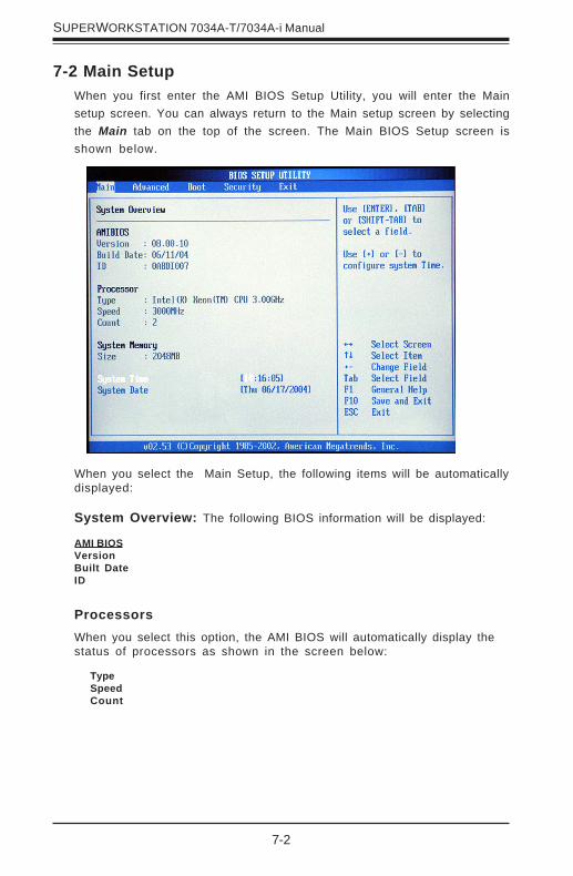
7-2
SUPERWORKSTATION 7034A-T/7034A-i Manual
ProcessorsWhen you select this option, the AMI BIOS will automatically display thestatus of processors as shown in the screen below:
TypeSpeedCount
7-2 Main SetupWhen you first enter the AMI BIOS Setup Utility, you will enter the Mainsetup screen. You can always return to the Main setup screen by selectingthe Main tab on the top of the screen. The Main BIOS Setup screen isshown below.
AMI BIOSVersionBuilt DateID
When you select the Main Setup, the following items will be automaticallydisplayed:
System Overview: The following BIOS information will be displayed:

Chapter 7: BIOS
7-3
System Time/System DateUse this option to change the system time and date. Highlight System Timeor System Date using the <Arrow> keys. Enter new values through thekeyboard. Press the <Tab> key or the <Arrow> keys to move betweenfields. The date must be entered in DAY/MM/DD/YY format. The time isentered in HH:MM:SS format.(*Note: The time is in 24-hour format. For ex-ample, 5:30 A.M. appears as 05:30:00, and 5:30P.M. as 17:30:00.)
System MemoryThis option allows the AMI BIOS to display the status of memory installed inthe system.
7-3 Advanced SettingsThe Advanced Settings screen and sub menus are listed below:
Warning
When you first enter the Advanced Setup screen, the Setup Warning willbe displayed. Please follow the instruction and set the correct value foreach item to prevent the system from malfunctioning.
SizeThis option allows the AMI BIOS to display the size of memory installed inthe system.
7-4
SUPERWORKSTATION 7034A-T/7034A-i Manual
Max CPUID Value Limit
This feature allows the user to set the maximum CPU ID value. Enable thisfunction to boot legacy OS that cannot support processors with extendedCPUID functions. The options are Enabled, and Disabled.
Hyper-Threading
This sett ing al lows you to Enable or Disable the funct ion of hyper-threading. Enabling hyper-threading results in increased CPU performance.
CPU Configuration Sub Menu
Configure Advanced CPU Settings
This option allows the user to configure Advanced CPU settings for theprocessor(s) installed in the system.
Ratio CMOS SettingThis option allows the user to set the ratio between the CPU Core Clockand the FSB Frequency. (*Note: if an invalid ratio is entered, AMIBIOS willrestore the setting to the previous state.)
VID CMOS Setting
This option sets the VID setting for the processor(s).

Chapter 7: BIOS
7-5
When you select this Sub Menu, the AMI BIOS automatically displays thestatus of the following items:
Onboard PCI IDE Operate Mode
This feature allows the user to set the Onboard PCI IDE Operation Mode.The options are: Native Mode and Legacy Mode. (*Please refer toAddendum D for information on Legacy Mode and Native Mode.)
IDE Configuration
This feature allows the user to set the IDE mode. The options are:Disabled, P-ATA (Parallel ATA) Only, S-ATA (Serial ATA) Only, and P-ATA & S-ATA. (*Please refer to Addendum D for Parallel ATA and SerialATA information.)
IDE Configuration Sub MenuThe screen for the Primary IDE Master is shown below:
Combined Mode Operation
This feature allows the user to select the IDE Combined Mode. Theoptions are: Disabled, P-ATA (Parallel ATA) 1ST Channel and S-ATA(Serial ATA 1st Channel).
P-ATA & S-ATA

7-6
SUPERWORKSTATION 7034A-T/7034A-i Manual
Primary IDE Master/Slave, Secondary IDE Master/Slave, ThirdIDE Master/Slave, Fourth IDE Master/Slave Sub Menu
From the Advanced Setup screen, press <Enter> to access this sub menufor the primary, secondary, third and fourth IDE master and slave drives.Use this screen to select options for the Primary and Secondary IDE drives.Use the up and down <Arrow> keys to select an item. Use the <Plus> and<Minus> keys to change the value of the selected option.
Type
Select the type of device connected to the system. The options are NotInstalled, Auto, CDROM and ARMD.
S-ATA Ports Definition
This feature allows the user to configure Serial ATA Ports. Theoptions are: P0-Master/P1-Slave, P0-Slave/P1-Master.
P-ATA Only
S-ATA Running Enhanced Mode
Select Yes if you want the function of Serial ATA Enanced Mode tobe enabled at all times. Options are Yes and No.
P-ATA Channel Selection
This feature allows the user to select which channel to set theParallel ATA Mode. The options are: Primary, Secondary or Both.
S-ATA Ports Definition
This feature allows the user to configure Serial ATA Ports. Theoptions are: P0-3rd/P1-4th, P0-4th/P1-3rd.
Configuring S-ATA as RAID
Select Yes to configure Serial ATA as RAID. The options are Yes,and No.
S-ATA Only
S-ATA Ports Definition
This feature allows the user to configure Serial ATA Ports. Theoptions are: P0-1st/P1-2nd, P0-2nd/P1-1st.

Chapter 7: BIOS
7-7
PIO Mode
IDE PIO (Programmable I/O) mode programs timing cycles between the IDEdrive and the programmable IDE controller. As the PIO mode increases,the cycle time decreases. The options are Auto, 0, 1, 2, 3, and 4" SelectAuto to allow the AMI BIOS to auto detect the PIO mode. Use this value ifthe IDE disk drive support cannot be determined. Select 0 to allow theAMI BIOS to use PIO mode 0. It has a data transfer rate of 3.3 MBs.Select 1 to allow the AMI BIOS to use PIO mode 1. It has a data transferrate of 5.2 MBs. Select 2 to allow the AMI BIOS to use PIO mode 2. It hasa data transfer rate of 8.3 MBs. Select 3 to allow the AMI BIOS to use PIOmode 3. It has a data transfer rate of 11.1 MBs. Select 4 to allow the AMIBIOS to use PIO mode 4. It has a data transfer rate of 16.6 MBs. Thissetting generally works with all hard disk drives manufactured after1999. For other disk drives, such as IDE CD-ROM drives, check the speci-fications of the drive.
LBA/Large Mode
LBA (Logical Block Addressing) is a method of addressing data on a diskdrive. In the LBA mode, the maximum drive capacity is 137 GB. For drivecapacities over 137 GB, your system must be equipped with 48-bit LBAmode addressing. If not, contact your manufacturer or install an ATA/133IDE controller card that supports 48-bit LBA mode. The options are Dis-abled or Auto.
Block (Multi-Sector Transfer)
Block mode boosts IDE drive performance by increasing the amount ofdata transferred. Only 512 bytes of data can be transferred per interruptif block mode is not used. Block mode allows transfers of up to 64 KBper interrupt. Select "Disabled" to allow the data to be transferred fromand to the device one sector at a time. Select "Auto" to allows the datatransfer from and to the device occur multiple sectors at a time if thedevice supports it. The options are Auto and Disabled.
Select Auto to allow the BIOS to auto detect the DMA mode. Use thisvalue if the IDE disk drive support cannot be determined. Select SWDMA0
DMA Mode
7-8
SUPERWORKSTATION 7034A-T/7034A-i Manual
S.M.A.R.T. For Hard disk drives
Self-Monitoring Analysis and Reporting Technology (SMART) can helppredict impending drive failures. Select "Auto" to allow the BIOS to autodetect hard disk drive support. Select "Disabled" to prevent the AMI BIOSfrom using the S.M.A.R.T. Select "Enabled" to allow the AMI BIOS to usethe S.M.A.R.T. to support hard drive disk. The options are Disabled,Enabled, and Auto.
32Bit Data Transfer
Select "Enabled" to activate the function of 32-Bit data transfer. Select"Disabled" to deactivate the function. The options are Enabled and Dis-abled.
Hard Disk Write Protect
Select Enabled to enable the function of Hard Disk Write Protect to preventdata from being written to HDD. The options are Enabled or Disabled.
IDE Detect Time Out
This feature allows the user to set the time-out value for detecting ATA,ATA PI devices installed in the system. The options are 0 (sec), 5, Mode 1.0,15, 20, 25, 30, and 35.
the BIOS to use Ultra DMA mode 1. It has a data transfer rate of 25 MBs.Select UDMA2 to allow the BIOS to use Ultra DMA mode 2. It has a datatransfer rate of 33.3 MBs. Select UDMA3 to allow the BIOS to use UltraDMA mode 3. It has a data transfer rate of 66.6 MBs. Select UDMA4 toallow the BIOS to use Ultra DMA mode 4 . It has a data transfer rate of100 MBs. The options are Auto, SWDMAn, MWDMAn, and UDMAn.
to allow the BIOS to use Single Word DMA mode 0. It has a data transferrate of 2.1 MBs. Select SWDMA1 to allow the BIOS to use Single WordDMA mode 1. It has a data transfer rate of 4.2 MBs. Select SWDMA2 toallow the BIOS to use Single Word DMA mode 2. It has a data transferrate of 8.3 MBs. Select MWDMA0 to allow the BIOS to use Multi WordDMA mode 0. It has a data transfer rate of 4.2 MBs. Select MWDMA1 toallow the BIOS to use Multi Word DMA mode 1. It has a data transfer rateof 13.3 MBs. Select MWDMA2 to allow the BIOS to use Multi-Word DMAmode 2. It has a data transfer rate of 16.6 MBs. Select UDMA0 to allowthe BIOS to use Ultra DMA mode 0. It has a data transfer rate of 16.6MBs. It has the same transfer rate as PIO mode 4 and Multi Word DMAmode 2. Select UDMA1 to allow
Chapter 7: BIOS
7-9
This feature allows the AMI BIOS to auto-detect 80Pin ATA(PI) Cable. Theoptions are: Host & Device, Host and Device.
ATA(PI) 80Pin Cable Detection
Floppy Configuration
This option allows the user to configure the settings for the Floppy Drivesinstalled in the system.
Floppy AMove the cursor to these fields via up and down <arrow> keys to selectthe floppy type. The options are Disabled, 360 KB 5 1/4", 1.2 MB 5 1/4",720 KB 3½", 1.44 MB 3½”, and 2.88 MB 3½". Default setting for FloppyA drive is 1.44 MB 3½”.
OnBoard Floppy ControllerSelect "Enabled" to enable the Onboard Floppy Controller. The options are"Disabled", and "Enabled."
7-10
SUPERWORKSTATION 7034A-T/7034A-i Manual
PCI/PnP Configuration
PCI Latency Timer
This option sets the latency of all PCI devices on the PCI bus. Select "32" toset the PCI latency to 32 PCI clock cycles. Select "64" to set the PCI latencyto 64 PCI clock cycles. Select "96" to set the PCI latency to 96 PCI clockcycles. Select "128" to set the PCI latency to 128 PCI clock cycles. Select"160" to set the PCI latency to 160 PCI clock cycles. Select "192" to set the
Allocate IRQ to PCI VGA
Set this value to allow or restrict the system from giving the VGA adaptercard an interrupt address. The options are Yes and No.
PCI IDE BusMaster
Set this value to allow or prevent the use of PCI IDE busmastering. Select"Enabled" to allow the AMI BIOS to use PCI busmaster for reading andwriting to IDE drives. The options are "Disabled" and "Enabled".
Offboard PCI/ISA IDE Card
This option allows the user to assign a PCI slot number to an Off-board PCI/ISA IDE card in order for it to function properly. The options are: Auto, PCISlot1, PCI Slot2, PCI Slot3, PCI Slot4, PCI Slot5, and PCI Slot6.
This feature allows the user to set PCI/PnP configurations for the followingitems:
Plug & Play OS
Select Yes to allow the OS to configure Plug & Play devices. (*This is notrequired for system boot if you system has an OS that supports Plug &Play.) Select No to allow the AMIBIOS to configure all devices in the system.
Palette Snooping
Select Enabled to inform the PCI devices that an ISA graphics device isinstalled in the system in order for the graphics card to function properly.The options are Enabled or Disabled.
PCI latency to 192 PCI clock cycles. Select "224" to set the PCI latency to224 PCI clock cycles. Select "248" to set the PCI latency to 248 PCI clockcycles.

Chapter 7: BIOS
7-11
IRQ3/IRQ4/IRQ5/IRQ7/IRQ9/IRQ10/IRQ11/IRQ14
This feature specifies the availability of an IRQ to be used by a PCI, PnPdevice. Select Reserved for the IRQ to be used by a Legacy ISA device.The options are: Available, Reserved.
Super IO Configuration Sub Menu
DMA Channel 0/DMA Channel 1/DMA Channel 3/DMA Channel 5/DMA Channel 6/DMA Channel 7
Select Available to indicate that a specific DMA channel is available tobe used by a PCI/PnP device. Select Reserved, if the DMA channelspecified is reserved for a Legacy ISA device.
Reserved Memory Size
This feature specifies the size of memory block to be reserved for LegacyISA devices. The options are: Disabled, 16K, 32K, 64K.
7-12
SUPERWORKSTATION 7034A-T/7034A-i Manual
Serial Port1 Address
This option specifies the base I/O port address and Interrupt Request ad-dress of serial port 1. Select "Disabled" to prevent the serial port fromaccessing any system resources. When this option is set to Disabled, theserial port physically becomes unavailable. Select "3F8/IRQ4" to allow theserial port to use 3F8 as its I/O port address and IRQ 4 for the interruptaddress. The options are Disabled, 3F8/IRQ4, 3E8/IRQ4, 2E8/IRQ3.
Serial Port2 Address
This option specifies the base I/O port address and Interrupt Request ad-dress of serial port 2. Select "Disabled" to prevent the serial port fromaccessing any system resources. When this option is set to "Disabled", theserial port physically becomes unavailable. Select "2F8/IRQ3" to allow theserial port to use 2F8 as its I/O port address and IRQ 3 for the interruptaddress. The options are Disabled, 2F8/IRQ3, 3E8/IRQ4, 2E8/IRQ3.
Parallel Port Address
This option specifies the I/O address used by the parallel port. SelectDisabled to prevent the parallel port from accessing any system resources.When the value of this option is set to Disabled, the printer port becomesunavailable. Select 378 to allow the parallel port to use 378 as its I/O portaddress. The majority of parallel ports on computer systems use IRQ7 andI/O Port 378H as the standard setting. Select 278 to allow the parallel port touse 278 as its I/O port address. Select 3BC to allow the parallel port to use3BC as its I/O port address.
Parallel Port Mode
Specify the paral le l port mode. The opt ions are Normal , Bi-directional, EPP and ECP.
Parallel Port IRQ
Select the IRQ (interrupt request) for the parallel port. The options
are IRQ5 and IRQ7.
Advanced Chipset SettingsThis item allows the user to configure the Advanced Chipset settings forthe system.

Chapter 7: BIOS
7-13
NorthBridge Configuration
This feature allows the user to configure the settings for Intel LindenhurstNorthBridge chipset.
Memory Remap Feature
Select Enabled to allow remapping of overlapped PCI memory above thetotal physical memory. The options are Enabled and Disabled.
Memory Mirroring and Sparing
Select Enabled to enable Memory RAS (-Mirroring and Sparing) to allowthe system to create a mirror copy of data written to the memory for datasecurity. The options are Disabled and Enabled.
SouthBridge Configuration
This feature al lows the user to configure the sett ings for Intel ICHSouthBridge chipset.
CPU B.I.S.T. Enable
Select Enabled to enable the function of CPU Built In Self Test. The optionsare Enabled and Disabled.
ICH Delayed Transaction
Select Enabled to enable the function of ICH Delayed Transaction to provideback-compatibility for slower components . The options are Enabled andDisabled.
ICH DCB Enable
Select Enabled to enable ICH DMA Collection Buffer. The options are En-abled and Disabled.
Onboard AC' 97 Audio
Select Auto to enable the function of Onboard AC'97 automatically. Theoptions are Auto, Enabled and Disabled.
7-14
SUPERWORKSTATION 7034A-T/7034A-i Manual
APCI Configuration
This item allows the user to enable or disable ACPI support for the operatingsystem.
General ACPI Configuration
Use this feature to configure additional ACPI options. Select "Yes" if theoperating system supports ACPI. Select No if the operating system does notsupport ACPI. The options are No and Yes.
Suspend Mode
This feature allows the user to select the ACPI state when the system ison the Suspend Mode. Select S1 if you want the system to standby.Select S3 to enable the function of Suspend to RAM, which will shortenbootup time after poweroff. The options are S1(POS) and S1&S3 (STR).
Advanced ACPI Configuration
Use this feature to configure additional ACPI options. Select "Yes" if theoperating system supports ACPI. Select No if the operating system does notsupport ACPI. The options are No and Yes.
ACPI 2.0 Features
Select Yes to allow RSDP pointers to point to the 64-bit Fixed SystemDescription Tables. Select No to deactivate this function. The options areYes and No.
ACPI APIC Support
Select Enabled to allow the ACPI APIC Table Pointer to be included in theRSDP pointer list. The options are Enable, and Disabled.
AMI OEMB Table
Select Enabled to allow the OEMB Table Pointer to be included in theR(x)SDT pointer lists. The options are Enabled, and Disabled.
Headless ModeSelect Enabled to activate the Headless Operation Mode through ACPI,which will allow the system to boot up and function properly withoutkeyboard and monitor display. The options are Enabled, and Disabled.

Chapter 7: BIOS
7-15
Power ConfigurationThis feature allows the user to configure PnP settings.
Power Button Mode
This setting allows you to decide if the power button will go into the On/Off mode or the Suspend mode if it is pressed. The options are On/Offand Suspend.
Restore on AC Power Loss
This setting allows you to choose how the system will react whenpower returns after an unexpected loss of power. The options arePower Off, Power On and Last State.
Watch Dog Timer
This setting is used to enable or disabled the Watch Dog Timer function. Itmust be used in conjunction with the WD jumper (see Chapter 2 for details).The options are Enabled and Disabled.
Event Log Configuration
Highlight this item and press <Enter> to view the contents of the event log.
View Event Log
This feature allows the user to view all unread events.
Mark All Events as Read
Highlight this item and press <Enter> to mark the DMI events as read.
Clear Event Logs
This setting will clear all event logs when set to "OK". The options are"OK" and "Cancel".
ECC Event Logging
This setting allows you to enable or disable ECC Event logging. The optionsare Enabled or Disabled.
Hub Interface Event Logging
This setting allows you to enable or disable Hub Interface Event logging.The options are Enabled or Disabled.
System Bus Event Logging
This setting allows you to enable or disable System Bus Event logging. Theoptions are Enabled or Disabled.
7-16
SUPERWORKSTATION 7034A-T/7034A-i Manual
MPS Configuration
This section allows the user to configure the multi-processor table.
MPS Revision
This feature allows the user to select MPS Revision. The options are 1.1 or1.4.
PCI Express Configuration
This section allows the user to configure PCI Express slots.
Active State Power Management
Select Enabled to activate the function of power management for signaltransactions between PCI Express L0 and L1 Link. The options are Enabledand Disabled.
I/O Expander Mode
This feature allows the user to set the IO Expand Mode for Hot Plug sup-port. The options are PCA9555, Two PCA9554, One PCA9554 (Low), OnePCA9554 (High), Two PCA9554A, One PCA9554A (Low), and OnePCA9554 (High).
PCI Express Port2 (Slot 1)
This feature allows the user to configure the PCI Express slot. The optionsare Auto, Enabled, and Disabled.
PCI Express Port4 (Slot 6)
This feature allows the user to configure the PCI Express slot. The optionsare Auto, Enabled, and Disabled.
PCI Express Compliance Mode
Select Enabled to enable MCH to activate PCI Express Compliance Mode.The options are Disabled and Enabled.
Memory Buffer Event Logging
This setting allows you to enable or disable Memory Buffer Event logging.The options are Enabled or Disabled.
PCI Error Logging
This setting allows you to enable or disable PCI Error logging. The optionsare Enabled or Disabled.
PCI Express Error Logging
This setting allows you to enable or disable PCI Express Error logging. Theoptions are Enabled or Disabled.

Chapter 7: BIOS
7-17
USB Configuration
Legacy USB SupportSelect "Enabled" to enable the support for USB Legacy. Disable legacysupport if there are no USB devices installed in the system. The optionsare Disabled, Enabled and Auto.
USB 2.0 Controller
This setting allows you to enable or disable USB 2.0 Controller. The optionsare Disabled or Enabled.
This feature allows you to enable 2 USB Ports or 4 USB Ports. Theoptions are Disabled, 2 USB Ports, and 4 USB Ports.
USB Function
This feature allows the user to disable the function of Remote Access. IfDisabled is not select, then you can select a Remote Access type. Theoptions are Enabled or Disabled.
Remote Access
Remote Access ConfigurationYou can use this screen to select options for the Remote Access Configu-ration. Use the up and down <Arrow> keys to select an item. Use the<Plus> and <Minus> keys to change the value of the selected option.
Spread Spectrum
Select Enabled to enable Spread Sperctrum. The options are Disabled andEnabled.
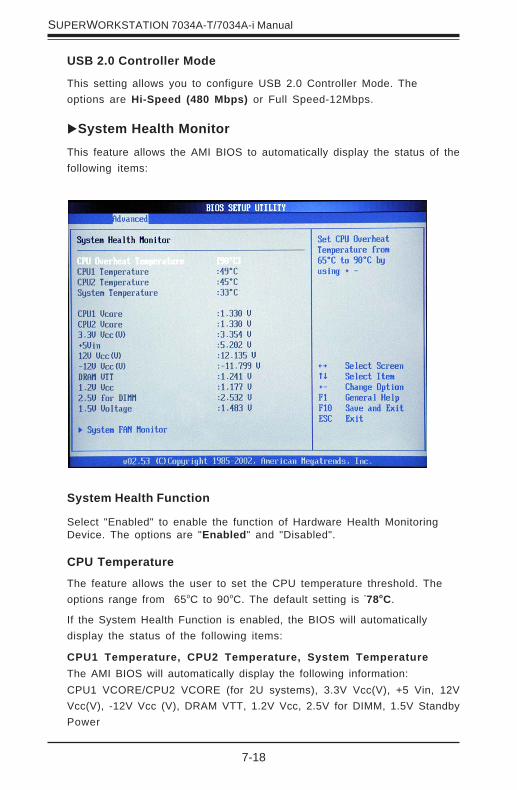
7-18
SUPERWORKSTATION 7034A-T/7034A-i Manual
CPU1 Temperature, CPU2 Temperature, System TemperatureThe AMI BIOS will automatically display the following information:CPU1 VCORE/CPU2 VCORE (for 2U systems), 3.3V Vcc(V), +5 Vin, 12VVcc(V), -12V Vcc (V), DRAM VTT, 1.2V Vcc, 2.5V for DIMM, 1.5V StandbyPower
System Health MonitorThis feature allows the AMI BIOS to automatically display the status of thefollowing items:
System Health Function
Select "Enabled" to enable the function of Hardware Health MonitoringDevice. The options are "Enabled" and "Disabled".
CPU Temperature
The feature allows the user to set the CPU temperature threshold. Theoptions range from 65oC to 90oC. The default setting is "78oC.
If the System Health Function is enabled, the BIOS will automaticallydisplay the status of the following items:
USB 2.0 Controller Mode
This setting allows you to configure USB 2.0 Controller Mode. Theoptions are Hi-Speed (480 Mbps) or Full Speed-12Mbps.

Chapter 7: BIOS
7-19
System Fan Monitor
This feature allows the user to decide how the system controls thespeed of the onboard fans. If the option is set to “3-pin fan”, the fanspeed is controlled based upon the CPU die temperature. When the CPUdie temperature is higher, the fan speed will be higher as well.
If the option is set to “4-pin”, BIOS will employ PWM (Pulse WidthModulation) to control fan speed according to the Thermal ManagementSettings, which may be pre-configured by the user.
Select “3-pin” if your serverboard has 3-pin fan headers. Select “4-pin” ifyour serverboard has 4-pin fan headers. Select “Workstation” if yoursystem is used as a workstation. Select “Server” if your system is usedas a server. Select “Disable” to disable the fan speed control functionand allow the onboard fans to run at full speed (12V) at all time. BIOSwill apply the chosen setting to all fan headers on the serverboard.
The options are "Disable", "3-pin (Server)", "3-pin (Workstation)", "4-pin(Server)" and "4-pin (Workstation)".
The recommended setting for the 7034A-T/7034A-i is "4-pin(Workstation)".
Note: loading the default settings into BIOS may change this setting. Ifyou do load BIOS defaults, you should reenter BIOS setup and changethis setting back to "4-pin (Workstation)", then save and exit.
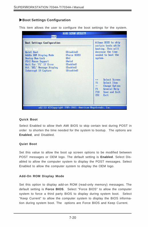
7-20
SUPERWORKSTATION 7034A-T/7034A-i Manual
Quiet Boot
Set this value to allow the boot up screen options to be modified betweenPOST messages or OEM logo. The default setting is Enabled. Select Dis-abled to allow the computer system to display the POST messages. SelectEnabled to allow the computer system to display the OEM logo.
Add-On ROM Display Mode
Set this option to display add-on ROM (read-only memory) messages. Thedefault setting is Force BIOS. Select "Force BIOS" to allow the computersystem to force a third party BIOS to display during system boot. Select"Keep Current" to allow the computer system to display the BIOS informa-tion during system boot. The options are Force BIOS and Keep Current.
This item allows the user to configure the boot settings for the system.
Quick Boot
Select Enabled to allow theh AMI BIOS to skip certain test during POST inorder to shorten the time needed for the system to bootup. The options areEnabled, and Disabled.
Boot Settings Configuration

Chapter 7: BIOS
7-21
Boot up Num-Lock
Set this value to allow the Number Lock setting to be modified during bootup. The default setting is On. The options are On and Off.
PS/2 Mouse Support
Set this value to allow the PS/2 mouse support to be modified. The optionsare Auto, Enabled and Disabled.
Wait for ‘F1’ If Error
Select Enable to activate the function of Wait for F1 if Error. The optionsare Enabled and Disabled.
Hit ‘DEL’ Message Display
Select Enabled to display Setup Message when the user hits the DEL key.The options are Enabled and Disabled.
Interrupt 19 Capture
Select Enabled to allow ROMs to trap Interrupt 19. The options are Enabledand Disabled.

7-22
SUPERWORKSTATION 7034A-T/7034A-i Manual
Boot Device PriorityThis feature allows the user to specify the sequence of priority for the BootDevice.
The settings are "1st Floppy Drive", "CD ROM", "HDD", and "Disabled." Thedefault settings are:
· 1st boot device –1st Floppy Drive
· 2nd boot device – CD ROM
· 3rd boot device – HDD
· 4th boot device – IBA GE Slot 02180
Hard Disk DrivesThis feature allows the user to specify the Boot sequence from availableHard Drives.
1st Drive
Specify the boot sequence for 1st Removable Drive. The options are 1stFloppy Drive and Disabled.
CD/DVD DrivesThis feature allows the user to specify the boot sequence from availableCDROM Drives.
1st Drive
Specify the boot sequence for 1st Hard Drive. The options are CD ROMand Disabled.
1st Drive/2nd DriveSpecify the boot sequence for 1st Hard Drive. The options are HDD andDisabled.
Removable DrivesThis feature allows the user to specify the Boot sequence from availableRemovable Drives.

Chapter 7: BIOS
7-23
Change Supervisor Password
Select this option and press <Enter> to access the sub menu, and then,type in the password.
Change User Password
Select this option and press <Enter> to access the sub menu, and then,type in the password.
Clear User Password
Select this option and press <Enter> to access the sub menu. You can usethe sub menu to clear the user password.
Boot Sector Virus Protection
This option is near the bottom of the Security Setup screen. Select "Dis-abled" to deactivate the Boot Sector Virus Protection. Select "Enabled" toenable boot sector protection. When "Enabled", the AMI BIOS displays awarning when any program (or virus) issues a Disk Format command orattempts to write to the boot sector of the hard disk drive. The options are"Enabled" and "Disabled".
7-4 Security Settings
the AMI BIOS provides a Supervisor and a User password. If you use bothpasswords, the Supervisor password must be set first.

7-24
SUPERWORKSTATION 7034A-T/7034A-i Manual
Discard Changes
Select this option and press <Enter> to discard all the changes and return tothe AMI BIOS Utility Program.
7-5 Exit Options
Select the Exit tab from the AMI BIOS Setup Utility screen to enter the Exitthe BIOS Setup screen.
Saving Changes and Exit
When you have completed the system configuration changes, select thisoption to leave the BIOS Setup and reboot the computer, so the newsystem configuration parameters can take effect. Select Save Changes andExit from the Exit menu and press <Enter>.
Discard Changes and Exit
Select this option to quit the BIOS Setup without making any permanentchanges to the system configuration and reboot the computer. Select Dis-card Changes and Exit from the Exit menu and press <Enter>.
Chapter 7: BIOS
7-25
Load Fail-Safe Defaults
To set this feature, select Load Fail-Safe Defaults from the Exit menu andpress <Enter>. The Fail-Safe settings are designed for maximum systemstability, but not maximum performance.
Load Optimal Defaults
To set this feature, select Load Optimal Defaults from the Exit menu andpress <Enter>. Then, Select "OK" to allow the BIOS to automatically loadOptimal Defaults to the BIOS Settings. The Optimal settings are designed formaximum system performance, but may not work best for all computer ap-plications.

7-26
SUPERWORKSTATION 7034A-T/7034A-i Manual
Notes

Appendix A
BIOS Error Beep/POST Codes
During the POST (Power-On Self-Test) routines, which are performedeach time the system is powered on, errors may occur.
Non-fatal errors are those which, in most cases, allow the system tocontinue the boot-up process. The error messages normally appear onthe screen.
Fatal errors are those which will not allow the system to continue theboot-up procedure. If a fatal error occurs, you should consult with yoursystem manufacturer for possible repairs.
These fatal errors are usually communicated through a series of audiblebeeps. The numbers on the fatal error list, on the following page,correspond to the number of beeps for the corresponding error. Allerrors listed, with the exception of Beep Code 8, are fatal errors.
POST codes may be read on the debug LEDs (DS7 and DS8) located besidethe LAN port on the motherboard backplane. See the description of thedebug LEDs (LED1 and LED2) in Chapter 5.
Appendix A: AMIBIOS Error Beep/POST Codes
A-1
A-1 AMIBIOS Error Beep Codes
Beep Code Error Message Description1 beep Refresh Circuits have
been reset. (Ready to power up.)
5 short, 1 long Memory error No memorydetected insystem
8 beeps Display memory read/write error Video adaptermissing or withfaulty memory
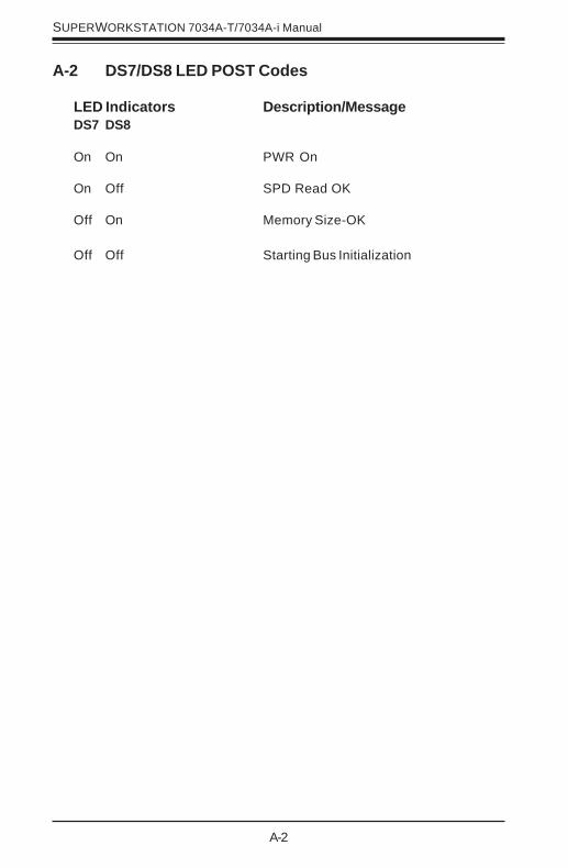
A-2
SUPERWORKSTATION 7034A-T/7034A-i Manual
A-2 DS7/DS8 LED POST Codes
LED Indicators Description/MessageDS7 DS8
On On PWR On
On Off SPD Read OK
Off On Memory Size-OK
Off Off Starting Bus Initialization
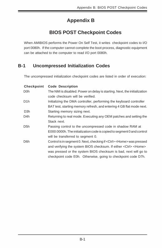
B-1
Appendix B: BIOS POST Checkpoint Codes
Appendix B
BIOS POST Checkpoint Codes
When AMIBIOS performs the Power On Self Test, it writes checkpoint codes to I/Oport 0080h. If the computer cannot complete the boot process, diagnostic equipmentcan be attached to the computer to read I/O port 0080h.
B-1 Uncompressed Initialization Codes
The uncompressed initialization checkpoint codes are listed in order of execution:
Checkpoint Code Description D0h The NMI is disabled. Power on delay is starting. Next, the initialization
code checksum will be verified. D1h Initializing the DMA controller, performing the keyboard controller
BAT test, starting memory refresh, and entering 4 GB flat mode next.D3h Starting memory sizing next.
D4h Returning to real mode. Executing any OEM patches and setting theStack next.
D5h Passing control to the uncompressed code in shadow RAM atE000:0000h. The initialization code is copied to segment 0 and controlwill be transferred to segment 0.
D6h Control is in segment 0. Next, checking if <Ctrl> <Home> was pressedand verifying the system BIOS checksum. If either <Ctrl> <Home>was pressed or the system BIOS checksum is bad, next will go tocheckpoint code E0h. Otherwise, going to checkpoint code D7h.

B-2
SUPERWORKSTATION 7034A-T/7034A-i Manual
B-2 Bootblock Recovery Codes
The bootblock recovery checkpoint codes are listed in order of execution:
Checkpoint Code DescriptionE0h The onboard floppy controller if available is initialized. Next,
beginning the base 512 KB memory test.E1h Initializing the interrupt vector table next.E2h Initializing the DMA and Interrupt controllers next.
E6h Enabling the floppy drive controller and Timer IRQs. Enabling internalcache memory.
Edh Initializing the floppy drive. Eeh Looking for a floppy diskette in drive A:. Reading the first sector of
the diskette.Efh A read error occurred while reading the floppy drive in drive A:.F0h Next, searching for the AMIBOOT.ROM file in the root directory.F1h The AMIBOOT.ROM file is not in the root directory.F2h Next, reading and analyzing the floppy diskette FAT to find the
clusters occupied by the AMIBOOT.ROM file.F3h Next, reading the AMIBOOT.ROM file, cluster by cluster.F4h The AMIBOOT.ROM file is not the correct size.F5h Next, disabling internal cache memory.FBh Next, detecting the type of flash ROM.FCh Next, erasing the flash ROM.FDh Next, programming the flash ROM.
FFh Flash ROM programming was successful. Next, restarting thesystem BIOS.
B-3 Uncompressed Initialization Codes
The following runtime checkpoint codes are listed in order of execution.These codes are uncompressed in F0000h shadow RAM.
Checkpoint Code Description 03h The NMI is disabled. Next, checking for a soft reset or a power on
condition.05h The BIOS stack has been built. Next, disabling cache memory.06h Uncompressing the POST code next.07h Next, initializing the CPU and the CPU data area.08h The CMOS checksum calculation is done next.0Ah The CMOS checksum calculation is done. Initializing the CMOS status
register for date and time next.0Bh The CMOS status register is initialized. Next, performing any required
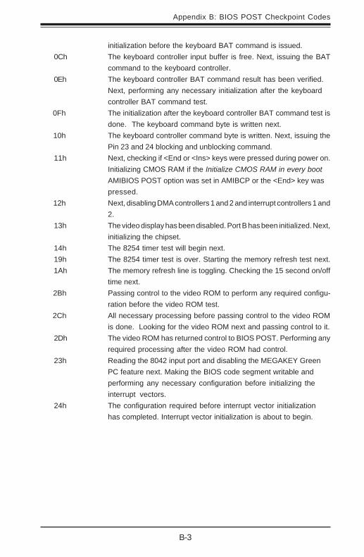
B-3
Appendix B: BIOS POST Checkpoint Codes
initialization before the keyboard BAT command is issued.0Ch The keyboard controller input buffer is free. Next, issuing the BAT
command to the keyboard controller.0Eh The keyboard controller BAT command result has been verified.
Next, performing any necessary initialization after the keyboardcontroller BAT command test.
0Fh The initialization after the keyboard controller BAT command test isdone. The keyboard command byte is written next.
10h The keyboard controller command byte is written. Next, issuing thePin 23 and 24 blocking and unblocking command.
11h Next, checking if <End or <Ins> keys were pressed during power on.Initializing CMOS RAM if the Initialize CMOS RAM in every bootAMIBIOS POST option was set in AMIBCP or the <End> key waspressed.
12h Next, disabling DMA controllers 1 and 2 and interrupt controllers 1 and2.
13h The video display has been disabled. Port B has been initialized. Next,initializing the chipset.
14h The 8254 timer test will begin next.19h The 8254 timer test is over. Starting the memory refresh test next.
1Ah The memory refresh line is toggling. Checking the 15 second on/offtime next.
2Bh Passing control to the video ROM to perform any required configu-ration before the video ROM test.
2Ch All necessary processing before passing control to the video ROMis done. Looking for the video ROM next and passing control to it.
2Dh The video ROM has returned control to BIOS POST. Performing anyrequired processing after the video ROM had control.
23h Reading the 8042 input port and disabling the MEGAKEY GreenPC feature next. Making the BIOS code segment writable andperforming any necessary configuration before initializing theinterrupt vectors.
24h The configuration required before interrupt vector initializationhas completed. Interrupt vector initialization is about to begin.
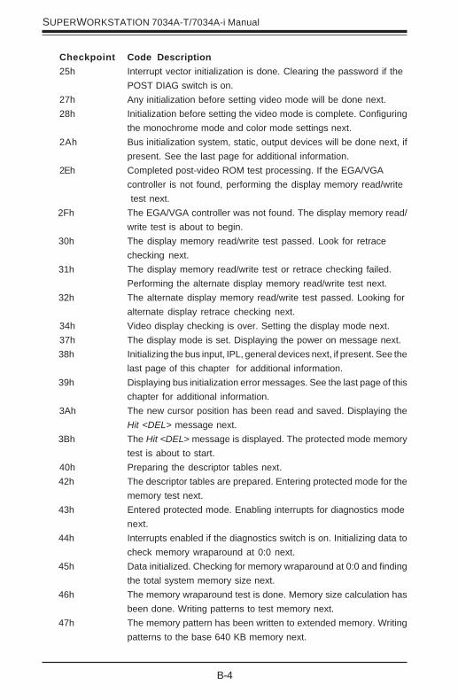
B-4
SUPERWORKSTATION 7034A-T/7034A-i Manual
Checkpoint Code Description25h Interrupt vector initialization is done. Clearing the password if the
POST DIAG switch is on.27h Any initialization before setting video mode will be done next.28h Initialization before setting the video mode is complete. Configuring
the monochrome mode and color mode settings next.2Ah Bus initialization system, static, output devices will be done next, if
present. See the last page for additional information.2Eh Completed post-video ROM test processing. If the EGA/VGA
controller is not found, performing the display memory read/write test next.
2Fh The EGA/VGA controller was not found. The display memory read/write test is about to begin.
30h The display memory read/write test passed. Look for retracechecking next.
31h The display memory read/write test or retrace checking failed.Performing the alternate display memory read/write test next.
32h The alternate display memory read/write test passed. Looking foralternate display retrace checking next.
34h Video display checking is over. Setting the display mode next.37h The display mode is set. Displaying the power on message next.
38h Initializing the bus input, IPL, general devices next, if present. See thelast page of this chapter for additional information.
39h Displaying bus initialization error messages. See the last page of thischapter for additional information.
3Ah The new cursor position has been read and saved. Displaying theHit <DEL> message next.
3Bh The Hit <DEL> message is displayed. The protected mode memorytest is about to start.
40h Preparing the descriptor tables next. 42h The descriptor tables are prepared. Entering protected mode for the
memory test next. 43h Entered protected mode. Enabling interrupts for diagnostics mode
next. 44h Interrupts enabled if the diagnostics switch is on. Initializing data to
check memory wraparound at 0:0 next. 45h Data initialized. Checking for memory wraparound at 0:0 and finding
the total system memory size next. 46h The memory wraparound test is done. Memory size calculation has
been done. Writing patterns to test memory next. 47h The memory pattern has been written to extended memory. Writing
patterns to the base 640 KB memory next.
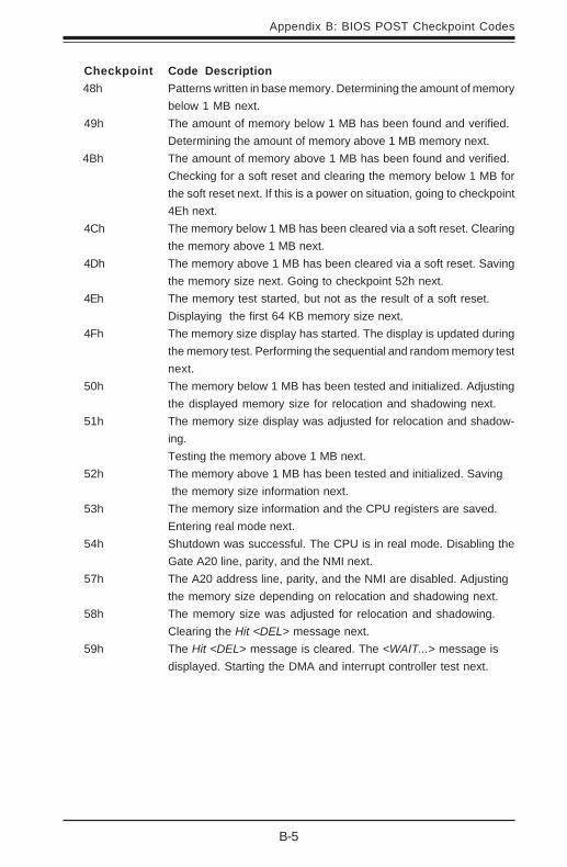
B-5
Appendix B: BIOS POST Checkpoint Codes
Checkpoint Code Description 48h Patterns written in base memory. Determining the amount of memory
below 1 MB next.49h The amount of memory below 1 MB has been found and verified.
Determining the amount of memory above 1 MB memory next. 4Bh The amount of memory above 1 MB has been found and verified.
Checking for a soft reset and clearing the memory below 1 MB forthe soft reset next. If this is a power on situation, going to checkpoint4Eh next.
4Ch The memory below 1 MB has been cleared via a soft reset. Clearingthe memory above 1 MB next.
4Dh The memory above 1 MB has been cleared via a soft reset. Savingthe memory size next. Going to checkpoint 52h next.
4Eh The memory test started, but not as the result of a soft reset.Displaying the first 64 KB memory size next.
4Fh The memory size display has started. The display is updated duringthe memory test. Performing the sequential and random memory testnext.
50h The memory below 1 MB has been tested and initialized. Adjustingthe displayed memory size for relocation and shadowing next.
51h The memory size display was adjusted for relocation and shadow-ing.Testing the memory above 1 MB next.
52h The memory above 1 MB has been tested and initialized. Saving the memory size information next.
53h The memory size information and the CPU registers are saved.Entering real mode next.
54h Shutdown was successful. The CPU is in real mode. Disabling theGate A20 line, parity, and the NMI next.
57h The A20 address line, parity, and the NMI are disabled. Adjustingthe memory size depending on relocation and shadowing next.
58h The memory size was adjusted for relocation and shadowing.Clearing the Hit <DEL> message next.
59h The Hit <DEL> message is cleared. The <WAIT...> message isdisplayed. Starting the DMA and interrupt controller test next.

B-6
SUPERWORKSTATION 7034A-T/7034A-i Manual
Checkpoint Code Description60h The DMA page register test passed. Performing the DMA Controller
1 base register test next.62h The DMA controller 1 base register test passed. Performing the DMA
controller 2 base register test next.65h The DMA controller 2 base register test passed. Programming DMA
controllers 1 and 2 next.66h Completed programming DMA controllers 1 and 2. Initializing the 8259
interrupt controller next.67h Completed 8259 interrupt controller initialization.7Fh Extended NMI source enabling is in progress.80h The keyboard test has started. Clearing the output buffer and
checking for stuck keys. Issuing the keyboard reset command next.81h A keyboard reset error or stuck key was found. Issuing the keyboard
controller interface test command next.82h The keyboard controller interface test completed. Writing the com-
mand byte and initializing the circular buffer next.83h The command byte was written and global data initialization has
completed. Checking for a locked key next.84h Locked key checking is over. Checking for a memory size mismatch
with CMOS RAM data next.85h The memory size check is done. Displaying a soft error and checking
for a password or bypassing WINBIOS Setup next.86h The password was checked. Performing any required programming
before WINBIOS Setup next.87h The programming before WINBIOS Setup has completed.
Uncompressing the WINBIOS Setup code and executing theAMIBIOS Setup or WINBIOS Setup utility next.
88h Returned from WINBIOS Setup and cleared the screen. Performingany necessary programming after WINBIOS Setup next.
89h The programming after WINBIOS Setup has completed. Displaying thepower on screen message next.
8Bh The first screen message has been displayed. The <WAIT...>message is displayed. Performing the PS/2 mouse check andextended BIOS data area allocation check next.
8Ch Programming the WINBIOS Setup options next.8Dh The WINBIOS Setup options are programmed. Resetting the hard disk
controller next.8Fh The hard disk controller has been reset. Configuring the floppy drive
controller next. 91h The floppy drive controller has been configured. Configuring the hard
disk drive controller next.

B-7
Appendix B: BIOS POST Checkpoint Codes
Checkpoint Code Description 95h Initializing the bus option ROMs from C800 next. See the last page of
this chapter for additional information.96h Initializing before passing control to the adaptor ROM at C800.
97h Initialization before the C800 adaptor ROM gains control has com-pleted. The adaptor ROM check is next.
98h The adaptor ROM had control and has now returned control to BIOSPOST. Performing any required processing after the option ROMreturned control.
99h Any initialization required after the option ROM test has completed.Configuring the timer data area and printer base address next.
9Ah Set the timer and printer base addresses. Setting the RS-232 baseaddress next.
9Bh Returned after setting the RS-232 base address. Performing anyrequired initialization before the Coprocessor test next.
9Ch Required initialization before the Coprocessor test is over. Initializingthe Coprocessor next.
9Dh Coprocessor initialized. Performing any required initialization afterthe Coprocessor test next.
9Eh Initialization after the Coprocessor test is complete. Checking theextended keyboard, keyboard ID, and Num Lock key next. Issuing thekeyboard ID command next.
A2h Displaying any soft errors next. A3h The soft error display has completed. Setting the keyboard typematic
rate next. A4h The keyboard typematic rate is set. Programming the memory wait
states next. A5h Memory wait state programming is over. Clearing the screen and
enabling parity and the NMI next.A7h NMI and parity enabled. Performing any initialization required before
passing control to the adaptor ROM at E000 next. A8h Initialization before passing control to the adaptor ROM at E000h
completed. Passing control to the adaptor ROM at E000h next. A9h Returned from adaptor ROM at E000h control. Performing any
initialization required after the E000 option ROM had control next. Aah Initialization after E000 option ROM control has completed. Displaying
the system configuration next. Abh Uncompressing the DMI data and executing DMI POST initialization
next.B0h The system configuration is displayed.B1h Copying any code to specific areas.
00h Code copying to specific areas is done. Passing control to INT 19hboot loader next.

B-8
SUPERWORKSTATION 7034A-T/7034A-i Manual
Notes

C-1
Appendix C: System Specifications
Appendix C
System Specifications
ProcessorsSingle or dual 604-pin Intel® XeonTM processors at a front side (system)bus speed of 800 MHz. (Please refer to the support section of our website for a complete listing of supported processors: www.supermicro.com).
ChipsetIntel E7525 chipset
BIOS8 MB AMI® Flash ROM
Memory CapacitySix 184-pin DIMM sockets supporting up to 12 GB of registered ECCDDR333 or 24 GB of registered ECC DDR266 SDRAM
Note: Interleaved memory - requires memory to be installed two at a time. See thememory section in Chapter 5 for details.
Serial ATA Controller (7034A-T only)Marvell SATA controller providing a four-port Serial ATA subsystem.
Peripheral Drives/BaysOne (1) 3.5" floppy driveTwo (2) 5.25" drive baysFour (4) SATA drive bays (7034A-T only)
Expansion SlotsChassis: Seven (7) I/O chassis slotsServerboard: total of six (6) PCI-Express/PCI-X slots

C-2
SUPERWORKSTATION 7034A-T/7034A-i Manual
Serverboard (7034A-T/7034A-i)Model: X6DAL-TG/X6DAL-G (Extended ATX)Dimensions: 12 x 10 in (305 x 254 mm)
Chassis (7034A-T/7034A-i)Model: SC733T-645/SC733i-645 (tower)Dimensions: (WxHxD) 6.94" x 17.125 x 24.125 in. (17.6 x 435 x 612.8mm)
WeightGross (Bare Bone): 40 lbs. (18.2 kg.)
System Cooling (all fan speed controlled by BIOS setting: p. 7-19)One (1) 9-cm chassis fanOne (1) 12-cm exhaust fan
System Input RequirementsAC Input Voltage: 100-240 VACRated Input Current: 11A @ 90VRated Input Frequency: 50 to 60 Hz
Power SupplyRated Output Power: 645W (Model# SP645-PS, Part# PWS-0060)Rated Output Voltages: +12Vtotal (46A), +5V (30A), +3.3V (30A), +5Vsb(4.0A)
Operating EnvironmentOperating Temperature: 10º to 35º C (50º to 95º F)Non-operating Temperature: -40º to 70º C (-40º to 158º F)Operating Relative Humidity: 8% to 90% (non-condensing)Non-operating Relative Humidity: 5 to 95% (non-condensing)
Regulatory ComplianceElectromagnetic Emissions:FCC Class B, EN 55022 Class B, EN 61000-3-2/-3-3, CISPR 22 Class B
Electromagnetic Immunity:EN 55024/CISPR 24, (EN 61000-4-2, EN 61000-4-3, EN 61000-4-4,EN 61000-4-5, EN 61000-4-6, EN 61000-4-8, EN 61000-4-11)
C-3
Appendix C: System Specifications
Safety:EN 60950/IEC 60950-CompliantUL Listed (USA)CUL Listed (Canada)TUV Certified (Germany)CE Marking (Europe)

C-4
SUPERWORKSTATION 7034A-T/7034A-i Manual
Notes