Embed Size (px)
Citation preview

/7 AO-AI06 318 SCHNASEL ENGINEERING ASSOCIATES RICHMOND VA FIG 13/11NATIONAL DAM SAFETY PRORAM. LEATNERWOOD CREEK NUMBER 6 DAM !N--ETC(U).JUL 81 A E MARTIN. C S ANDERSON, J S STARR OACW6'-S1-OO0o
20
UNCLASSIFED N
*mlllmlllllllmmlEIIIIIIIIIIIIl
EI MEhhhhh11111111111!"
FIMNWE RIVR BABM
K* Name Of Dam: MON C301N. 6 .
Locaft: -12 Cow VIRZIA
hiventy Number: VA. NO. 08907
AD A10631S
PHASE I INSPECTION REPORTNATIONAL DAM SAFETY PROGRAM
PREAKD FUt
nwrFoLK MIThICT Com" OF 1N mineU 0 FRONT WMKhWmOmmOLK. V@INIA 2361
J. K. TDma Ammaciin ac.
im as 81 10 27 327
- .~- # -I
SECURITY CLASSIFICATION OF THIS PAGE (Ifte DetqR Entered) _________________
PAGE READ INSTRUCTIONSREPORT DOCUMENTATION PAEBEFORE COMPLETING FORM
1. REPORT wuto jZOTACSSO 4. RECIPIENT'S CATALOG NUMBER
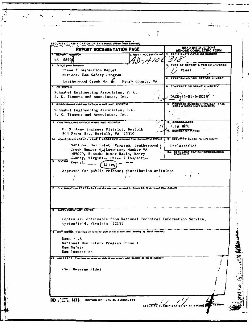
VA 089(A19D ~6 i fC TITLE (And Subtitl) S. ,TYPE OF REPORT & PERIOD I.A)VERED
Phase I Inspection Report FinalNational Dam Safety Program
Leatherwood Creek No. 41 Henry County, VA S EFRIGOG -- OTNME
7 AUT04OR1(s) S. CONTRACT OR GRANT NUMIDER(s)
Schnabel Engineering Associates, P. C..1. K. Timmons and Associates, Inc. / DACW65-81-D-002OK-
PERFORMING ORA1A0NNMEADADESI. PROGRAM ELEMENT. PROJECT. TASK(ORGAIZATON NME AD ADRESSAREA 4 WORK U NIT NUMBERS
Schnabel Engineering Associates, P.C.I1. K. Timmons and Associates, Inc.
IICONTROLLING OFFICE NAME AND ADDRESS 1.fiJGXQT
U.S ryEngineer District, NorfolkJuy18
803 Front St., Norfolk, VA 23510
V4 MONITORING AGENCY NAMIE A AOORESS(lI diffoene, frm, Controlling Office) IS. SECURITY CLASS. (of I.Vi report)
Nati,'nal Dam S a fety Progran. Leatherwood UnclassifiedGreek Number 6^(lnventory Number VA ~ DCASFCTO ONRDN
08907), Roanoke River Basin, Henry SCHEDULECounty, Virginia. Phase I Inspection -
5 1TIReport. ____ ? -
Apprved for publi 7t'cr pese; distribution unlimited
'7 DISTRIBUTION STATEMENT (of the mbetraco entered If Block 20. Il,u, sR.H
19 SUPPLEMENTARY worts
Coples ;ire obtainahle from National Technical Information Service,
Sprtngfteld, Virginia 22151
It K tY WORD0S (Co.,itue on Meeo oide it nec.eary and Idenfby block number)
Dams - VA~4aionaI Dam Safety Program Phanse I
Damn Safetya
20 ABSTRACT (Cotinue on ,eeee oid Of necessary 014 Idenfyhl by block nmber)
(Sep. Reverse Side)
.44
SECURITY CLASSIFICATION OF TNIS PAGE '
SECURITY CLASSIFICATION OF THIS PAGE(Wleai Date tnte e)
20. Abstract
Pursuant to Public Law 92- 67, Phase I Inspection Reports are preparedunder guidance contained I the recommended guidelines for safetyinspection of dams, publi d by the Office of Chief of Engineers,Washington, D. C. 20314. The purpose of a Phase I Inspection is toidentify expeditiously those dams which may pose hazards to human life orproperty. The assessment of the general conditions of the dam is basedupon available data and visual inspection. Detailed investigation andanalyses involving topographic mapping, subsurface investigations,testing, and detailed computational evaluations are beyond the scope of aPhase I investigation; however, the investigation is intended to identifyany need for such studies.
Based upon the field conditions at the time of the field inspection andall available engineering data, the Phase I report addresses thehydraulic, hydrologic, geologic, geotechnic, and structural aspects ofthe dam. The engineering techniques employed give a reasonably accurateassessment of the conditions of the dam. It should be realized thatcertain engineering aspects cannot be fully analyzed during a Phase Iinspection. Assessment and remedial measures in the report include therequirements of additional indepth study when necessary.
Phase I reports include project information of the dam appurtenances, allexisting engineering data, operational procedures, hydraulic/hydrologicdata of the watershed, dam stability, visual inspection report and anassessment including required remedial measures.
I..
CI
~SECURITY CLASSIFICATION OF THIS PAGE(fthn Date Entero(d

ROANOKE RIVER BASIN
NAME OF DAM: LEATHEYWO CREEK NO. 6 DAMILCATION: HENRY COUNTY, VIRGINIAINVENTORY NUMBER: VA. NO. 08907
PHASE I INSPECTION REPORT
NATIONAL DAM SAFT PROJGRAM
PREPAFED FORINQXROLK DISTRICT CORPS OF ENGINEERS
803 FROM1 STREETNORFOLK, VIRGINIA 23510
BY fSHNAB ENGINEERING ASSOCIATES, P.C./
J. K. TIMMONS AND ASSOCIATES, INC. I
- .,2--_ ___ I J . _ J ,II . . ; i -
L ..
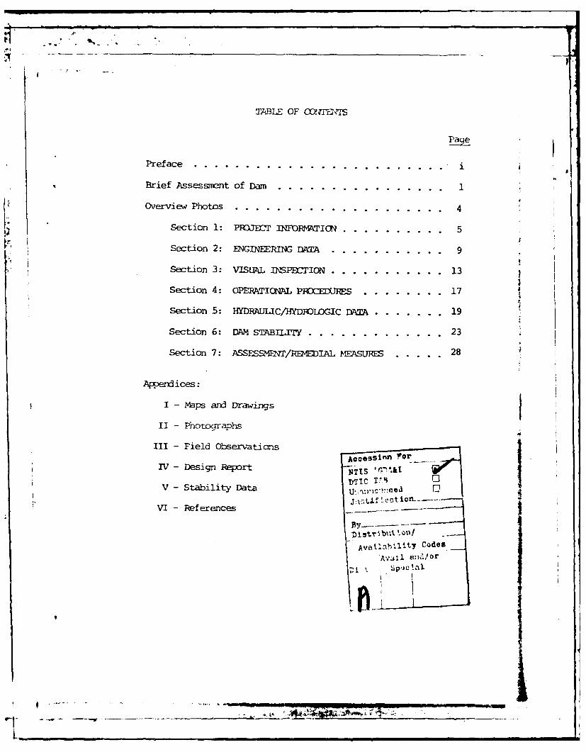
TABLE OF CXE2\'1S
Page
Preface ......... ..........................
Brief Assessment of Dam ....... ................ 1
Overview Photos .......... .................... 4
Section 1: PRJF INFORMATION .......... 5
Section 2: ENGINEERING DATA ..... ........... 9
Section 3: VISUAL DaSPE0TION .... ........... 13
Section 4: OPERATICNAL PIRXEXJRES. . ....... 17
Section 5: HYDRAULIC/HYDROIDGIC DATA ......... ... 19
Section 6: DAM STABIUITY.. .... ............. .23
Section 7: ASSESSMT/REDIAL PEASU1RES ..... 28
Appendices:
I - maps and Drawings
II - Photographs
III- Field Observations
TV - Design Report' .,DTIc Tt
V - Stability Data O. -,.I
VI - References
By- -- - -
Avaea 41t 7 CodesAv,l and/or
- .- - - - V - _ _ _ _ _ _ _ _ _ _ _ _ _ _ , _ __: _ __,_ _ _ __a_
_
I••
PFEFACE
This report is prepared under guidance contained in thePtecmmended Guidelines for Safety Inspection of Dams, for Phase IInvestigations. Copies of these guidelines may be obtained fronthe Office of chief of Engineers, Washington, D. C. 20314. Thepurpose of a Phase I Investigation is to identify expeditiouslythose dams which may pose hazards to human life or property. Theassessmet of the general condition of the dam is based uponavailable data and visual inspections. Detailed investigation, andanalyses involving topographic mapping, subsurface investigations,testing, and detailed computational evaluations are beyond the scopeof a Phase I Investigation; however, the investigation is intended toidentify any need for such studies.
In reviewing this report, it should be realized that the reportedcondition of the dam is based on observations of field conditions atthe time of inspection along .with data available to the inspectionteam. In cases where the reservoir was lowered or drained prior toinspection, such action, while improving the stability and safety ofthe dam, removes the normal load on the structure and may obscurecertain oonditions which might otherwise be detectable if inspectedunder the normal operating environment of the structure.
It is important to note that the condition of a dam depends onnumerous and constantly changing internal and external conditions,and is evolutionary in nature. It would be incorrect to assume thatthe present condition of the dam will continue to represent theconditioi of the dam at saie point in the future. Only throughfrequent inspections can unsafe conditions be detected and onlythrough continued care and maintenance can these conditions beprevented or corrected.
Phase I inspections are not intended to provide detailed hydrologicand hydraulic analyses. In accordance with the established Gaidelines,the Spillway Test flood is based on the estimated "Probable MaximunFlood" for the region (greatest reasonably possible stom runoff), orfractins thereof. Because of the magnitude and rarity of such astor event, a finding that a spillway will not pass the test floodshould not be interpreted as necessarily posing a highly inadequateconditim. The test flood provides a measure of relative spillwaycapacity and serves as an aid in detennining the need for nare detailedhydrologic and hydraulic studies, considering the size of the dam, itsgeneral condition and the downstream damage potential.
• , :_L .. . . . __ _ _ Is . .. .I _ L [ .. _ I
L,-.j.. .r e~ "'. "T . _-- .,. III

PHASE I REPORTNATIONAL DAM SAFETY PROGRAM
B
BRIEF ASSESS T OF DAM
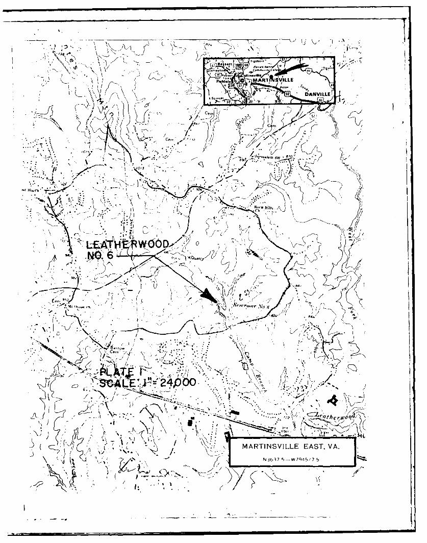
Name of Dam: Leathenwood Creek No. 6 DamState: VirginiaLocation: Henry CountyUSGS Quad Sheet: Martinsville EastCoordinates: Lat 360 41.6' Long 790 47.8Stream: Camp Branch of Leatherwood CreekDate of Inspection: July 1, 1981
ieatherwod Dam No. 6 is a homogeneous earthfill structure about
500 ft long and 31.9 ft high. The principal spillway consists of a
reinforced concrete riser and a 24 inch diameter concrete outlet pipe
which extends through the structure. An earth emergency spillway is
located at the left abutment with a 100 ft wide bottom and 3H:IV side
slopes. The structure is classified small in size and is assigned a
significant hazard classification. The dam is located on Camp Branch
of Leatherwxod Creek approximately 2.4 miles east of Martinsville,
Virginia. The dam is used for irrigation, flood control and
recreational purposes, and is owned and maintained by Camp Branch
Plantation, Inc.
Based on criteria established by the Department of the Army,
Office of the Chief of Engineers (OCE), the appropriate Spillway
Design Flood (SDF) is the h PMf. The spillways will pass 30 percent
of the Probable Maximn Flood (PMF) or 60 percent of the SDF without
overtopping the dam. During the SDF, the dam will be overtopped
• I

for a period of 2.0 hours up to a znaimur of 1.4 feet and reach a maximum
velocity of 5.1 fps. Flows overtopping the dam during the SDF are not
considered detrimental to the embankment with respect to erosion. The
spillway is judged inadequate, but not seriously inadequate.
The visual inspection did not reveal any problems which would
require immediate attention. A summary of the design stability analyses
for the upstream slope under drawdown conditions, and the downstream slope
under steady seepage codxitions were reviewed and found to be acceptable.
It is recomended that the owner implement an emergency action plan
measure to warn the downstream dwellings of any dangers which nay be
inminent.
The following routine maintenance and observation functions should
be initiated within the next twelve months:
The grass and weeds on the dam emankiment and in the emergency
spillway should be cut at least once a year and preferably twice a year.
Maintenance is recommended in the early sumner and fall. Existing trees
on the dam should be cut to the ground and removed. 0
Bare and rutted areas created by vehicular traffic on the crest of
the dam and in the emergency spillway should be backfilled and reseeded.
Vehicular traffic should be restricted in these areas. Eroded areas present
at pool level on the upstream slope should be monitored quarterly to detect
any significant increase in erosion which may require the installation of
riprap for slope protection. Fishermen should not be allowed to dig up the
efbankment and existing disturbed areas should be regraded and seeded.
--2-
4
L I=.=n- ---- i-

Foot paths on the embankment should also be reseeded. The eroded area
present below the berm on the downstream slope should be backfilled with
ccpacted soil and reseeded.
Debris should be renoved from the trash rack and vegetation should
be removed from the left seepage drain outlet. A staff gage should be
installed to nonitor water levels.
SCWQABEL GINEERfNG ASSOCIATES, P.C./J. K. TIM4MNS & ASSOCIATES, INC.
2Ray f. Main, 4h.D., P.E.Carrn th of Virginia
Submitted by: Approved:
Original signed by:' Original signed by:
Carl S. Anderson, Jr.. Ronald E. Hudson
Carl S. Anderson, Jr., P.E. Ronald E. HudsonActing Chief, Design Branch colonel, Corps of Engineers
cumander and District Engineer
Reccaxnnded by:
Original signed byJACK G. STARR Dte: SEP 23 1981
Jack G. Starr, P.E.Chief, Engineering Division 4
-3-
-,V

Leatherwood Dam No. 6 -Lake
Dam
Overview Photographs
-4-
SECTION 1 - PIR3ECT INFOR 4ATION
1. 1 General:
1.1.1 Authority: Public Law 92-367, 8 August 1972, authorized
the Secretary of the Army, through the Corps of Engineers, to initiate
a national program of safety inspection of dams throughout the United
States. The Norfolk District has been assigned the responsibility of
supervising the inspection of dams ir the Ccmmonwealth of Virginia.
1.1.2 Purpose of Inspection: The purpose is to conduct a
Phase I inspection according to the Recxmmnded Guidelines for Safety
Inspection of Dams (see Reference 1, Appendix VI). The main
responsibility is to expeditiously identify those dams which may be a
potential hazard to human life or property.
1.2 Project Description:
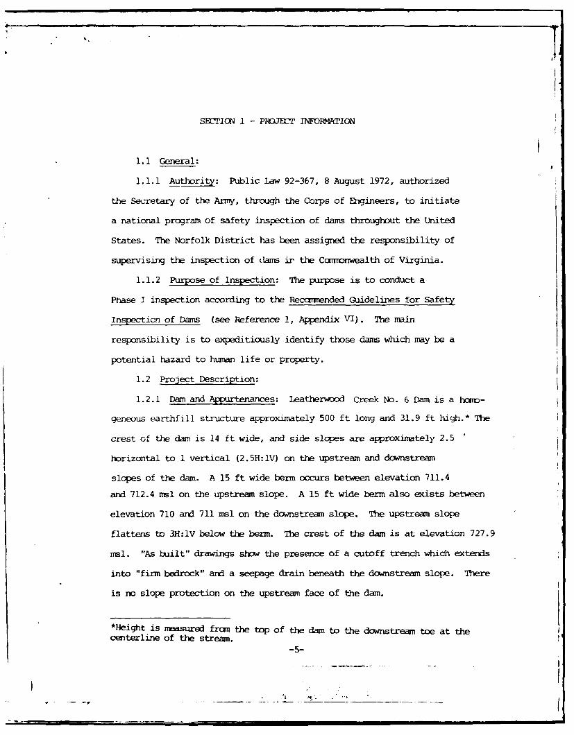
1.2.1 Dam and Appurtenances: Iatherwood Creek No. 6 Dam is a hom-
geneous earthfill structure approximately 500 ft long and 31.9 ft high.* The
crest of the dam is 14 ft wide, and side slopes are approximately 2.5
horizontal to 1 vertical (2.5H:lV) on the upstream and downstream
slopes of the dam. A 15 ft wide berm occurs between elevation 711.4
and 712.4 msl on the upstream slope. A 15 ft wide berm also exists between
elevation 710 and 711 msl on the downstream slope. The upstream slope
flattens to 3H:lV below the berm. The crest of the dam is at elevation 727.9
msl. "As built" drawings show the presence of a cutoff trench which extends
into "firm bedrock" and a seepage drain beneath the downstream slope. There
is no slope protection on the upstream face of the dam.
*Height is masured from the top of the dam to the downstream toe at thecenterline of the stream.
-5-
%i
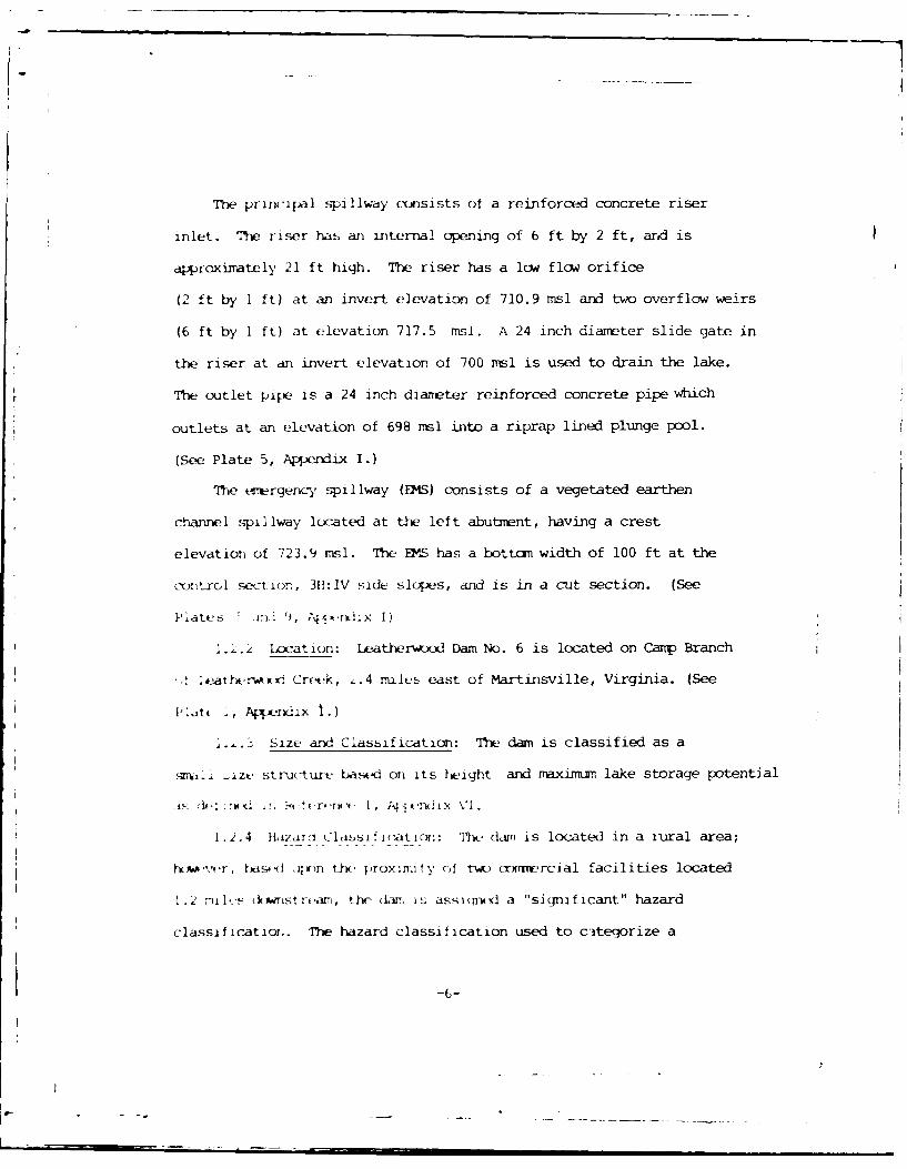
Tbe principal sqpillwdy c-onsists of a reinforced concrete riser
inlet. The riser has an internal opening of 6 ft by 2 ft, and is
approxirately 21 ft high. The riser has a low flow orifice
(2 ft by I ft) at an invert elevation of 710.9 rnsl and two overflow weirs
(6 ft by 1 ft) at elevation 717.5 msl. A 24 inch diamter slide gate in
the riser at an invert elevation of 700 insl is used to drain the lake.
The outlet pipe is a 24 inch diameter reinforced concrete pipe which
outlets at an elevation of 698 ml into a riprap lined plunge pool.
(See Plate 5, Apperdix I.)
The t~ergency spillway (EMS) consists of a vegetated earthen
channel spillway located at the left abutment, having a crest
elevation of 723.9 rnsl. The 71w S has a bottom width of 100 ft at the
control section, 3H:IV side slopes, and is in a cut section. (See
1.1.2 Location: Lether-od Dam No. 6 is located on CaMp Branch
leater xl Creek, 2.4 nuiles east of Martinsville, Virginia. (See
I...3 Size and Classification: The dam is classified as a
T~i .izu structure based on its height and rraximum lake storage potential
1.2.4 Hi,,zarci Cla.%ss~!ction: 'I1'h dam is located in a ,ural area;
w .- ,.r, ~soqt , ;r t , prox im fy of t-w cxxrTmrcial facilities located
1.2 milVs (kiwMTstit.am, the (lam is assiMq(d a "siqnificant" hazard
classificat . The hazard classification used to citegorize a
L--- --

dam is a function of location only and has nothing to do with its
stability or probability of failure.
1.2.5 Ownership: The dam is owned and maintained by Camp Branch
Plantation, Inc. of Martinsville, Virginia.
1.2.7 Design and Construction History: The dam was designed and
constructed under the supervision of the United States Department of
Agriculture (USDA), Soil Conservation Service (SCS). The structure
was constructed by Larramore Construction Company and completed in
1964.
1.2.8 Nirmal Operational Procedures: The principal spillway is
ungated, therefore, water rising above the low level orifice and overflow
weirs of the riser outlet is autcuatically discharged downstream. Normal
pool is maintained at elevation 711 msl just above the invert of the low
level orifice in the riser. Flood discharges which cannot be absorbed
by storage and the riser flow through the emergency spillway at pool
elevations above 723.9 msl. The 24 inch diameter gate at elevation 700 msl
is manually operated, and is available to lower the lake elevation below
normal pool for maintenance purposes.
1.3 Pertinent Data:
1.3.1 Drainage Area: The drainage area is 2.1 square miles.
1.3.2 Discharge at Dam Site:
-7-
F T,
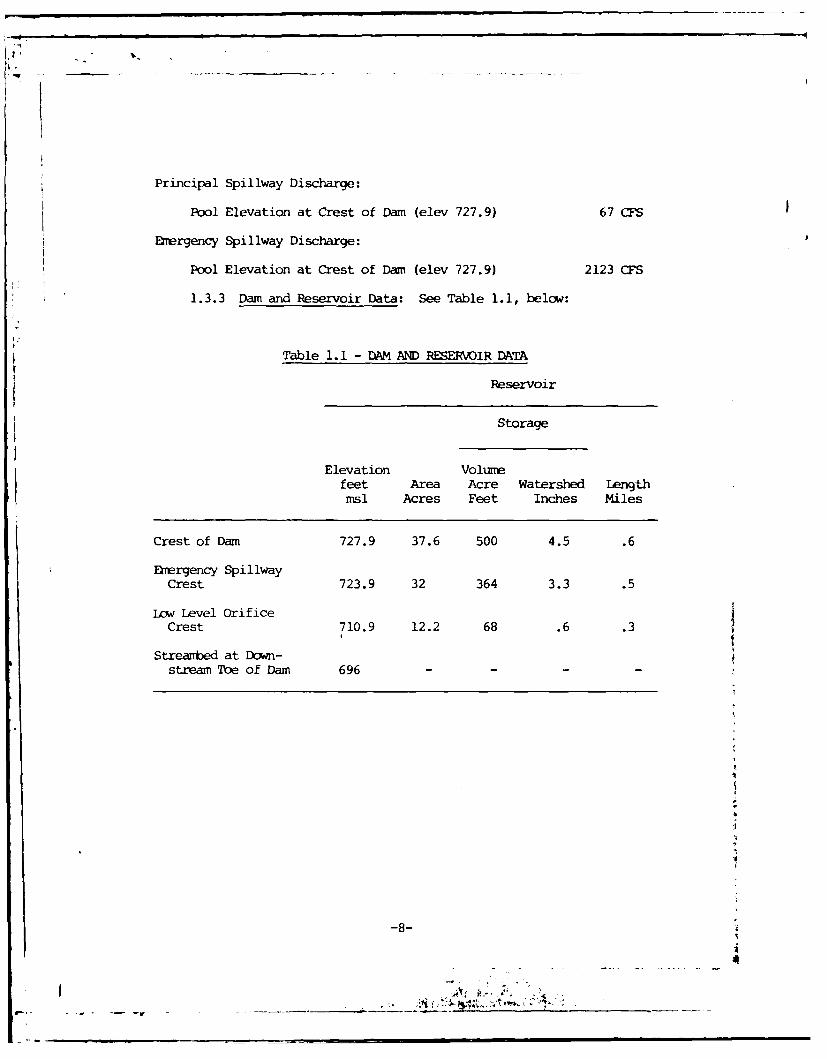
Principal Spillway Discharge:
Pool Elevation at Crest of Dam (elev 727.9) 67 CFS
Emergency Spillway Discharge:
Pool Elevation at Crest of Dam (elev 727.9) 2123 CFS
1.3.3 Dam and Reservoir Data: See Table 1.1, below:
Table 1.1 - DAM AND RESERVOIR DATA
Reservoir
Storage
Elevation Volumefeet Area Acre Watershed Lengthmsl Acres Feet Inches Miles
Crest of Dam 727.9 37.6 500 4.5 .6
Emergency SpillwayCrest 723.9 32 364 3.3 .5
Low Level OrificeCrest 710.9 12.2 68 .6 .3
Streambed at Down-stream Toe of Dam 696 - - -
-8-
4
SI-f ltI'J 2 - F-4UN1iNC DATA
2.1 rLsi_: The dam was designed and constxucted under the
direction of the USDA, Soil Conservation Service (SCS). "As built"
drawings and dvsigfn data are available in the office of the State
Conservationist, U. S. Soil Conservation Service, Federal Buildinq, Roan
9201, 5th and Marshall Streets, Richtnd, Virginia 23240.
A subsurface investigation was conducted at the site by the SCS
during the initial design stages. The investigation consisted of
excavating 71 test pits and drilling 2 hand augers. Subsurface profiles
and a report of the investigation with foundation recomendations were
prepared based upon geologic field reconnaissance, test pit and hand auger
data, and laboratory testing. A copy of the design report is included as
NApendix IV. Test pit and hand auger locations are provided on Plate 2
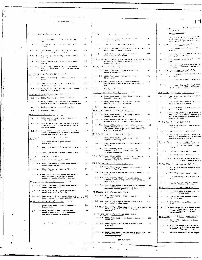
of Appendix I. Subsurface profiles are shown on Plates 3 and 4 of
Appendix I, while logs of the materials encountered are included as Plates
C, 7 and 8 of Appendix I.
The dam is a hcuogeneous, compacted earthfill entankment. The earthfill
requrrements shown on Plate 5 of Appendix I specify that ?41, ML and SC
materials be placed in the cutoff trench, center and upstream section of
the dam. Soil classification is by the Unified Soil Classification System,
ASTM D-2487. The non-plastic SM material was to be placed in the down-
stream section as directed by the Engineer. "As built" ebarknent slopes for i
the structure are illustrated on Plate 5 of Appendix I.
-9-I

A rV\'icw of desimn data iricates the dam is founde-d on overburden
and inclxks a cutoff trenrich which extends through alluvial and residual
soils into "firm bedrock." The cutoff also extends to the same materials
in both abutments. The cutoff trench has a bottom width of 12 ft and
IH:IV side slopes. No field pt.rntability tests were taken during the
subsurfact, invest iqat ion.
An internal drainage system was also constructed beneath the down-
stream slope to collect any seepage passing through the dam. The seepage
drain consists of a 3 ft mininu width trench of variable depth. It is
approximately 348 ft in length and includes 320 ft of perforated and 48 ft
of non-perforated bituminous coated corrugated metal pipe. The aMP is
enclosed in an envelope of graded filter material. Details for the "as
built" seepage drain are included on Plate 4 of Appendix I.
The principal spillway was designed as a drop inlet structure consisting
of a reinforced concrete riser, a 24 inch conduit and plunge pool at the
outlet end of the conduit. The emergency spillway (EMS) is designed as
an earth cut at the left abutment. The principal spillway was designed
to accommodate a 50 year flood without the pool elevation exceeding the
EM crest.
The emergency spillway is located in a moderately sloping hillside
in the left abutment. The spillway is a 100 ft wide trapezoidal earthen
and weathered rock channel bounded by 3H:IV cut slopes. The spillway is
entirely in cut materials, i.e., residual soils and weathered rock. The
emergency spillway was to be undercut I ft below final grade and backfilled
-10-
L- . --
L

with "semi-corpacted" select borrow material. All materials encountered in
the subsurface investigation were dry and well-drained. Details of the
spillway section are given on Plate 2 of Appendix I.
The design report and supplementary data provided by SCS (Appendix V)
includes laboratory test data describing the physical properties of the
materials used to construct the embankment. Shear strength parameters were
assumed for the foundation materials while strength parameters used in de-
sign of the enbankment were determined by oonsolidated-undrained triaxial
compression tests. Strength parameters, are listed below:
SECTION SOIL SHEAR STRENG"M PARAMETERSAngle of
Internal Friction Cohesion
Embankment ML Ocu = 28.00 c = 200 psf
MH Ocu = 15.50 c = 525 psf
SM Ocu = 28.5 c = 500 psf
Foundation ML 0 = 0 c = 200 psf
The stability of the embankment was checked for two conditions using
the Swedish Circle Method of Analysis. The first analysis considered the
embankment alone with a fully developed phreatic line. In this analysis, a
2.5H:IV downstream slope without drainage was used and a factor of safety
of 1.43 was calculated for the lowest strength materials tested. It was
concluded that a slightly higher factor of safety would exist for anj
upstream slope of 2.5H:lV over 3H:lV with a 10 ft berm under full or rapid
drawdown.
The second analysis considered 6 ft of foundation material with an
in-situ shear strength of 0 = 0, c = 200 psf. Assuming a moist embankment,
SCS stated that the conditions of this analysis represented a situation where
A?IT-11-
L .II

no consolidation of foundation soils would occur during construction.
Using saturated shear strength values from triaxial tests, a factor of
safety of 1.22 was calculated for the upstream slope (2.5H:lV over 3H:lV)
and 1.07 for the downstream slope (2.5H:lV).
It was stated in the slope stability stmmary that, "It must be
* c'*hasized that this analysis is not conclusive since it is based on an
average strength of c = 200 psf derived frcm pocket penetrumeter readings."
2.2 Construction: The construction records were not furnished
by the SCS office in Richmond, but they are available from the SCS
office in Washington, D. C.
2.3 Evaluation: "As built" drawings are representative of the
structure. Hydrologic and hydraulic calculations were available forI evaluation. There is sufficient information to evaluate foundation
conditions and embankment stability.
I
i
I
I
-12-
I L
r ,-
-SJ
SBCTION 3 - VISUAL INSPECTION
3.1 Findings: At the time of inspection, the dam appeared to be
in good condition. Field observations are outlined in Appendix III.
3.1.1 General: An inspection was made on July 1, 1981 and the
weather was cloudy with a temperature of 85°F. The pool and tailwater
levels at the tine of inspection were 711 and 696 msl, respectively,
which corresponds to normal pool and tailwater elevations. Ground
conditions were dry at the time of the inspection. Maintenance inspections are
performed jointly by SCS and the Blue Ridge Soil and Water Conservation
District on an annual basis. Inspection reports are available in the Soil
and Water Conservation District office in Collinsville, Virginia.
3.1.2 Dam and Spillway: The embankment slopes were heavily vegetated
with tall grass, brush, briers or blackberry bushes and honeysuckle making
observation difficult. Scattered small trees less than 2 inches in
diameter occur at various locations at pool level and up to 5 ft above
pool level on the upstream slope. A roadway traverses the crest of the dam.
The embankment crest exhibited considerable rutting due to vehicular
traffic. The ruts range from to 1 ft! in depth and are up to 1 ft± wide.
Scattered shrinkage cracks were observed in non-vegetated areas of the
embankment. Scattered shallow erosional channels or washes occur along
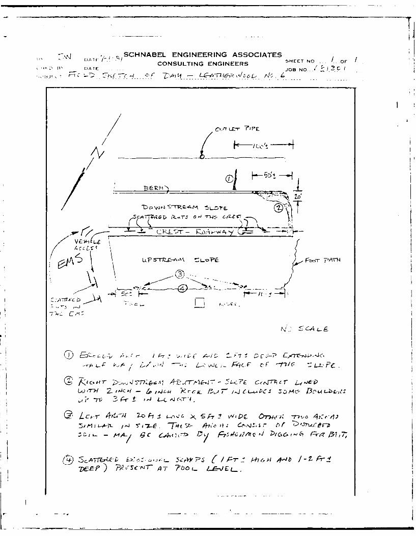
the upstream slope, particularly near pool level. Three disturbed areas
were also observed on the upstream slope just above pool level as shown
on the Field Sketch, Appendix III. These areas are believed to
be the result of fishermen digging for bait. Scattered erosional
scarps 1 ft± high extend 1 to 2 ft± into the upstream slope at
pool level and appear to be the result of wave erosion. A bare
-13-
r-I - . ..
L L P-,, j,, , I , II III I I
foot path occurs along the right side of the upstream slope providing
access to the lake. Another such path extends across the base of the
upstream slope just above pool level. The only erosion observed on the
downstream slope is an eroded area 1 ft+ wide and 2 ft+ deep which begins
at the downstream slope berm extending half way down the remaining slope
(see Field Sketch, ?ppendix III). A riprap channel lines the right
abutnnt-downstream slope contact from the embankment crest to the lower
berm. The riprap gutter appears to be rather new and may have been
installed to restrict erosion. It is not shown on the "as built" drawings.
The downstream toe was dry and no seepage was observed. Two 6-inch
CMP toe drains exist on either side of the principal spillway outlet. There
was no flow from the left drain, the lower half of which was filled with
vegetation. Flow fran the right drain was clear and estimated at gpm-.
The riser structure and outlet pipe showed no signs of deterioration
and were functioning properly at the time of inspection. Debris was
present in the low flow intake trash rack. The plunge pool and outlet
channel indicated no signs of deterioration. The emergency spillway
was well vegetated except for some minor erosion caused by vehicle
traffic.
3.1.3 Reservoir Area: The reservoir area was free of debris and
the perimeter was wooded. The reservoir is located in a valley with
with moderate side slopes. The water was clear and no sedimentation
was observed.
-14-
- v -- 1-
I-
3.1.4 Downstream Area: The downstream channel consists of a 10 ft
wide channel located in a 200 ft wide flood plain, and a valley with
steep side slopes. The valley is heavily wooded with thick underbrush.
Approximately 1.2 miles downstream there are two commercial facilities
about 15 ft above the stream channel.
3.1.5 Instrurentation: No instrumentation (monuments, observation
wells, piezometers, etc.) was encountered for the structure. There is
no staff gage.
3.2 Evaluation:
3.2.1 Dam and Spillway: Overall, the dam was in good condition at the
time of the inspection. An annual inspection and maintenance program exists
for this structure, however, at the tine of this inspection, maintenance
appeared to be inadequate. The embankment, including its crest and
slope should be mowed at least once a year, but more preferable twice
a year. The presence of trees on the embankment, particularly any at
pool level on the upstream slope, may promote the development of deep-
rooted vegetation and this type growth can encourage piping within an
ernbnkrent. All trees growing on the embankment should be cut to the
ground and removed from the embankment.
The bare areas and rutting created by vehicular traffic on the crest
of the dam and in the emergency spillway do not inhibit the proper
performance of the dam, however, it is recommended that these areas be
backfilled and reseeded. The presence of an adequately vegetated crest
reduces the erodibility of the crest should overtopping of the dam 4
occur during flooding. Vehicle traffic should be restricted on the dam
and emergency spillway. The shrinkage cracks observed are believed to be
the result of local drought conditions and do not require any specialp4
-15-
i cj: , .

attention. The erosion observed at pool level on the upstream slope
was not widespread at the time of the inspection. If this erosion should
increase significantly and become more widespread in ocurrence, it may be
necessary to place riprap for erosion protection. Fishermen should not be
allowed to dig up the embankment, and existing disturbed areas should be
regraded and seeded. The foot paths on the right upstream slope and just
above pool level should also be reseeded. The eroded area present below
the berm on the downstream slope should be backfilled with cxrpacted soil
and reseeded to prevent further erosion.
The right seepage drain outlet was functioning properly, however,
the lower half of the left drain outlet was filled with vegetation. This
vegetation should be removed. The outlet pipe and intake structures are
in good structural condition. Debris should be removed from the trash rack.
A staff gage should be installed to monitor water levels.
3.2.2 Downstream Area: A breach in the Leatherwood Creek No. 6 Dam
during extreme flooding would create a hazard to the downstream dwellings.
-16-

SEX1ION 4 - OPERATIONAL PRXEDURES
4.1 Procedures: The normal storage pool is elevation 711 msl or
0.1 ft above the crest of the principal spillway low flow inlet. The
lake provides an irrigation supply, flood control and recreation.
Water autcmatically passes through the principal spillway as the water
level in the reservoir rises above the low level orifice. Water will
also pass autcmatically through the riser overflow crest when the
water level in the reservoir exceeds elevation 717.5 msl, and automatic-
ally through the emergency spillway when the pool level exceeds
elevation 723.9 ml. A 24 inch dianeter slide gate at the low point in
the riser structure is provided to drawdown the reservoir below normal
pool.
4.2 Maintenance of Dam and AIpurtenances: Maintenance is the
responsibility of the owner and the Blue Ridge Soil and Water Conservation
District. Maintenance is accomplished by a joint inspection by SCS and
Soil and Water Conservation District personnel. Maintenance deficiencies
are noted and recomended remedial measures are made to the owner. If the
owner fails to comply with these reacmuendations, maintenance is then
performed by the Blue Ridge Soil and Water Conservation District.
4.3 Warning System: At the present time, there is no warning systen
or evacuation plan for the dam. The dam is monitored by SCS during periods
of heavy precipitation and runoff.
-17-
+4
-- I-li ---
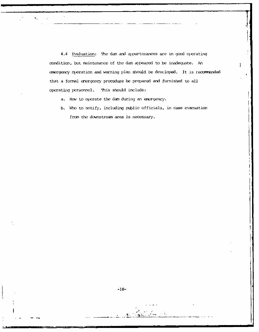
,1*4.4 Evaluation: The dam and appurtenances are in good operating
condition, but maintenance of the dam appeared to be inadequate. An
ergency operation and warning plan should be developed. It is reconverKed
that a formal emergency procedure be prepared and furnished to all
operating personnel. This should include:
a. How to operate the dam during an emergery.
b. Who to notify, including public officials, in case evacuation
from the downstream area is necessary.
-18-

- Ij~l I 'fY U A)LfkUI ; I C I)ATA
I. Ixsap Irw W j2 No. 6 was d;ihdby thc Soil
CcrVrt ioi. ';,-rvice i575 ,d a Tul t i-purpew ;, dc-rn, and hydro.,ogic and
hydi-auliza data is aV al.Staco--storaqc xid aeishredata
from the des igo, iepurt we-re use4-d in the2 evaluation. This structure is
a Class- "A" dam accevrfinq to the SCS classification nuI-tho~d.
5.2) Hvdipoqic I-a-t rds: There are no rec-ords available.
5.3 Flood K> eriunce: lrdormitior. on tlcxxi expqerienyc was
riot ava.lahle.
.4 VIIcx-xi Potentials: in accordance with the established guide-
.Ines,, tht! Spi'lway LX-icpi Flcxxl (SI;DE) is based o,,- the estimated
"I'ruLx:: 't Maxirmrn l~~ or the-- rcion (flxr- cischarges thtt mity bt
cxj~c~edfror, the nust SC,'L:''- oom'bination of critical rmterologic ana
~,~iOIXfCccndit.I(o,;!z that uirt reasonaly PossibLi in theC rt.'ion) , Cr
:raci'tI onZ tjnureof. IThe IProbLabic NxrntFlcx-K' (') and M' and 100
2ear f.Lixx hydrcxgraphs were develcoped by the IEC-i ID B Corr-iter Program
(Rufeurt2:ice 4, A~eKL<VI) . Prciltation aruiuts for the fior hydrograph
of theit PIT' a-nd 100 y~ear flood werc taken fromri e U. S. Weathecr Bureau
if oration (Ref erences 5 and ',, Aqjpe-nd-x VIl). Apropriate adjustrn'entz
for basin size and shape were accounted for. The~se hydrograpY~s were
routed through the reservoir to determi-ne iraxirrui pool elevations.
-19-

,1
. , j I I' A i I1j1J,.: 1", routing purp)se-s, the pool at
, ;IJ.:,:; ,f 1,joi7 ww:! ,1 LJ t L-L at elevation 711 nsl.
sg .- s~tiuiucL.lt.1 ariJ trye-diktarge data were utilized
i,,u tjt ,,., -C I.)rt. FIK-'ds were routed through the
i-.. u ,; r~ti p, I,,',I .aIl.'av uischarge up to a Pool storage
h,'at i, ; ,.9 ::-c And a Er. principal and emergency
;,-. c,.v t (c'rs al,':,L 723.9 msl. Pool elevations above
-17.9 r wt. w,,t, routed o \;V the ;o:r-overflc section of the dam.
5.6 (,'tort-a29fLn Potentiial: Thrt predicted rise of the reservoir
p xl and otl . p .rtimt.t data wer, uct-rvuned by routing the flood
rhroUgt' tit rt ,sCrvi :i< previously described. The
Al I I t I ( Xd CC' 1 (A IF y'ar flood, 'I PF and PMF) are
~r;. v , 1 ,! , ' c Ta£le 5. 2:
-20-
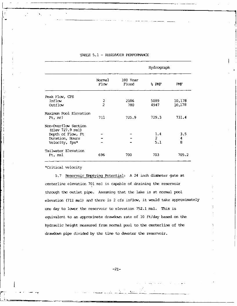
TABLE 5.1 - RESERVOIR PERFORMANCE
Hydrograph
Normal 100 YearFlow Flood PMF PMF
Peak Flow, CFSInflow 2 2186 5089 10,178Outflow 2 780 4947 10,178
Maximum Pool ElevationFt, ms] 711 725.9 729.3 731.4
Non-Overflow Section(Elev 727.9 msl)
Depth of Flow, Ft - - 1.4 3.5Duration, Hours - - 2 4Velocity, fps* - 5.1 8
Tailwater ElevationPt, msl 696 700 703 705.2
*Critical velocity
5.7 Reservoir Emptying Potential: A 24 inch diameter gate at
centerline elevation 701 msl is capable of draining the reservoir
through the outlet pipe. Assuming that the lake is at normal pool
elevation (711 msl) and there is 2 cfs inflow, it would take approximately
one day to lower the reservoir to elevation 752.1 msl. This is
equivalent to an approximate drawdown rate of 10 ft/day based on the
hydraulic height measured fran normal pool to the centerline of the
drawdown pipe divided by the time to dewater the reservoir.
-21-
L . . ... . ....
5.8 L\'aludtion: The U. S. Arml,, Corps of Engineers' guidelines
indicate the appiopriate Spillway Design Flood (SDF) for a small
size, significant hazard dam is the 100 year flood to PMF. Because
of the risk involved, the PMF has been selected as the SDF. The
spillway will pass 30 percent of the PMF without overtopping the crest
of the dan (60 percent of the SDF). During the SDF, the darn will be
r overtopped for a period of 2 hours up to a maximm of 1.4 feet and reach
a nm-ximum velocity of 5.1 fps.
Hydrologic data used in the evaluation pertains to present day
conditions with no consideration given to future development.
-22-
9-- -- - - ... ---- ------------- ,-.---- ------
SE2TION 6 - DAM STABILITY
6.1 Foundation and Abutments: The dam is located along the
western edge of the Piedmont Physiographic Province of Virginia. The
original design report described the site as being underlain by the
Wissahickon Formation; however, recent detailed mapping indicates the
site is actually underlain by the Rich Acres Formation of Precambrian
Age (1020 million years old). The Rich Acres Formation consists of
coarse-grained norites, metamorphosed gabbros and diorites. These rocks
are simular in texture to granites, but are comprised of more basic or
dark colored minerals. Less than 500 ft west of the dam site the
Prccambrian Leatherwood Granite is exposed. This material, typically
granitic dikes and thin sheets on top of the Rich Acres Formation, is
thought to be derived frcmn the same magma as the Rich Acres Formation.
Detailed geologic maps of the area do not indicate the presence of any
faults in the site vicinity. Site geology is presented in more detail
in the Design Geologic Report, which is included as Appendix IV.
Bedrock underlying the site includes a relatively thin weathered
zone consisting of disintegrated rock and/or residual soils. At the dam
site the residual soils are overlain by up to 9 ft of alluvial deposits.
The alluvium generally consists of silts and silty clays underlain by
saturated sands and gravels. The centerline of the dam was excavated to
hard rock except at the abutments of the dam. No rock was encountered with
the backhoe in either abutment. The foundation contains an irregular
rockline due to the intrusion of more resistant dikes into the surrounding
-23-
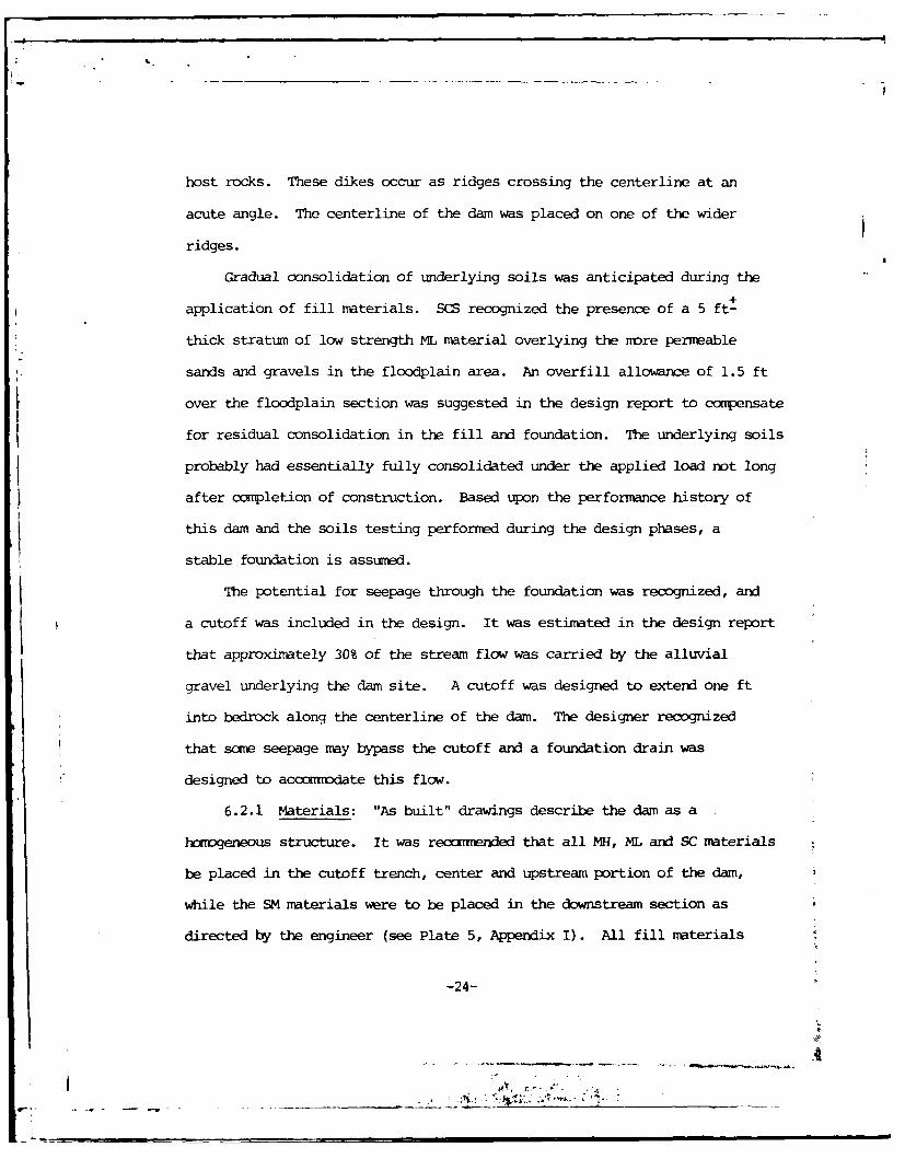
host rocks. These dikes occur as ridges crossing the centerline at an
acute angle. The centerline of the dam was placed on one of the wider
ridges.
Gradual consolidation of underlying soils was anticipated during the
application of fill materials. SCS recognized the presence of a 5 ft-
thick stratum of low strength ML material overlying the more permeable
sands and gravels in the floodplain area. An overfill allowance of 1.5 ft
over the floodplain section was suggested in the design report to compensate
for residual consolidation in the fill and foundation. The underlying soils
probably had essentially fully consolidated under the applied load not long
after completion of construction. Based upon the performance history of
this dam and the soils testing performed during the design phases, a
stable foundation is assumed.
The potential for seepage through the foundation was recognized, and
a cutoff was included in the design. It was estimated in the design report
that approximately 30% of the stream flow was carried by the alluvial
gravel underlying the dam site. A cutoff was designed to extend one ft
into bedrock along the centerline of the dam. The designer recognized
that some seepage may bypass the cutoff and a foundation drain was
designed to acconodate this flow.
6.2.1 Materials: "As built" drawings describe the dam as a
hoviogeneous structure. It was reconmnended that all NH, ML and SC materials
be placed in the cutoff trench, center and upstream portion of the dam,
while the SM materials were to be placed in the downstream section as
directed by the engineer (see Plate 5, Appendix I). All fill materials
-24-
ki :-L :".
. ... . . - -

were to be compacted to 95% of maximum dry density in accordance with
ASTM Standard D-698 (Standard Proctor). Ccnpacted densities and shear
strength values for the embankment materials are sumnmarized on pages 2 and5
3 of Appendix V. Specifications for maximum lift thickness and maximum
rock sizes were not observed in the design data provided.
6.2.2 Subdrains and Seepage: In attempt to control seepage, a cutoff
was constructed into bedrock below the more permeable alluvial soils in
the floodplain and extending into the abutments. Details are shown on
Plate 3 of Appendix I. An internal drainage system was also constructed,
consisting of a drainage trench beneath the downstream portion of the
embankment to collect any seepage which may occur. Drainage pipes were
provided for transmitting the collected water to the plunge pool. Details
are provided on Plate 4 of Appendix I. During the field inspection, no
flow was observed from the left seepage drain outlet, however, the right
outlet was iron-stained and clear water was flowing from the outlet at+
gpm-. In attempt to prevent piping around the principal spillway pipe,
5 anti-seep collars were included as shown on Plate 5 of Appendix I.
6.2.3 Stability: A stability analysis was performed for this
structure and the report describing the engineering design data used is
included as Appendix V. These data were reviewed along with the stablity
analysis and were found to be acceptable. In the first condition,
assuming the embankment alone with a fully developed phreatic line, a
factor of safety of 1.43 was calculated for a 2.5H:lV downstream slope
without drainage. A slightly higher factor of safety was concluded under
full or rapid drawdown for an upstream slope of 2.5H:lV over 3H:IV with
-25-

a 10 ft berm. The second analysis considered 6 ft of foundation material
with an in-situ shear strength of 0 = 0, c = 200 psf (based upon pocket
penetrcmeter readings). Assuming a moist embankment and no consolidation
of foundation soils during construction, a factor of safety of 1.22 was
calculated for the upstream slope (2.5H:lV over 3H:IV) and a factor of
safety of 1.07 for the downstream slope (2.5H:IV).
The dam is 32 ft high and has a crest width of 14 ft. The upstream
slope is 2.5H:IV with a 15 ft wide berm at pool level between elevations
711.4 and 712.4 msl. The upstream slope then continues at a 3H:lV slope
below normal pool. The downstream slope is 2.5H:lV with a 15 ft wide
berm between elevations 711.0 and 710.0 msl dipping into the dam. The
dam is subjected to a sudden drawdown since the lake level can be drawn
down at a rate of 10 ft/day. This exceeds the critical rate of 0.5 ft
per day for earth dams.
6.2.4 Seismic Stability: The dam is located in Seismic Zone 2.
Therefore, according to the Recommnded Guidelines for Safety Inspection
of Dams, the dam is considered to have no hazard from earthquakes provided
static stability conditions are satisfactory and conventional safety
margins exist.
6.3 Evaluation: In the SCS stability report (Appendix V) uncertainties
with regard to the strength of the soft ML zone were recognized. Consequently,
the following recxmrendations were made: "(1) Removal of all or part of
the low density material fran the foundation..., (2) Determine the shear
strength of the ML zone from undisturbed samples, (3) Or provide additional
berming both upstream and downstream" The "as built" drawings indicate
-26-

that the last recommendation was utilized in design and construction of
the dan.
For the purpose of this evaluation it is assumed that the additional
berming provides adequate factors of safety, altxugh it is not known if
any further stability analyses were performed. It is likely that the
factors of safety are above those re nerKned in Reference 1, Appendix VI,
since (1) a conservative value (c = 200 psf) was originally assumed for
the foundation soils, (2) the original factors of safety developed from
slope stability analyses did not account for an increase of strength
during consolidation, and (3) the berming on the downstream slope and
additional berming on the upstream slope will modify the slope
configuration resulting in a higher factor of safety. Based upon the
visual inspection, performance history and the design report, the
foundation is considered sound and the embankment is considered stable.
Overtopping is not considered detrimental to the dam with respect
to erosion because of the shallow depth and short duration of flood.
Also the critical velocity is slightly less than 6 fps, the assumed
effective eroding velocity for a vegetated earth embankment.
Since no undue settlement, cracking or sloughing was noted at the
time of inspection, it appears that the embankment is adequate for
maximum control storage with water at elevation 711 msl.
i
-27-
tI
.4a
SECTION 7 - ASSESSMEN/RFMEDIAL MEASURES
7.1 Dam Assessnent: Sufficient engineering data is available for
assessing the dam. The visual inspection revealed no findings that proved
the dam to be unsound. There is an annual inspection and maintenance
program for this structure, but there is no emergency operation and warning
plan. Overall, the dam was in good condition at the time of inspection.
U. S. Army, Corps of Engineers guidelines indicate the appropriate Spillway
Design Flood (SDF) for this dam is the PMF. The spillway will pass 30
percent of the PMF (60 percent of the SDF) without overtopping the crest
of the dam. During the SDF, the dam will be overtopped for a period of
2.0 hours up to a maximum of 1.4 feet and reach a maximum velocity of 5.1 fps.
Flows overtopping the dam at a maximum velocity of 5.1 fps during the SDF
are not considered detrimental to the embankment with respect to erosion.
The spillway is judged inadequate, but not seriously inadequate. Review of
available stability data indicates the structure is stable as designed.
7.2 Recommended Remedial Measures:
7.2.1 Emergency Operation and Warning Plan: It is recomended that
a formal emergency procedure be prepared, prominently displayed, and furnished
to all operating personnel. This should include:
1) How to operate the dam during an emergency.
2) Who to notify, including public officials, in case evacuation
frcm the downstream area is necessary.
7.3 Required Maintenance: The inspection revealed the following
maintenace items that should be scheduled by the owner during a regular
maintenance period within the next 12 months.
-28-
- 4.- -. -_ ___
a) The grass and i, ces on the darn eubankmnt should be cut at
least once a year and preferably twice a year. Maintenance
is recomnended in the early stumier and fall.
b) Existing trees on the dam should be cut to the ground. Cut
trees should be remved from the embankment.
c) Bare and rutted areas created by vehicular traffic on the
crest of the dam and in the emrgency spillway should be
backfilled and reseeded.
d) Vehicle traffic should be restricted on the dam and in the
emrgency spillway.
e) Eroded areas present at pool level on the upstrea slope
should be nonitored quarterly to detect any significant
increase in erosion, which my require the installation of
riprap for slope protection.
f) Fishermen should not be allowed to dig up the embankmnt
and existina disturbed areas should be regraded and seeded.
q) Foot paths on the embankmient should be reseeded.
h) The eroded area present below the berm on the downstream slope
should be backfilled with comp)acted soil and reseeded.
i) Debris should be removed fron the trash rack.
j) Vegetation should be removed from the left seepage drain
outlet.
k. A staff gage should be installed to monitor water levels.
-29-
s . . dp
" *'* "*-t -*P

-APPENDIX I
NAPS AND DRAWinGS
- -A
F/goo I I ao
/1 DANVILLE
/~~~~ /'cr nC
N\\ (.~~ Z#' / 'jr~. 1 / -
.. ~--1 - ZX/
-S K~ z
"$ H..~ - ~* - 1
~'21
E~ '2
.1JZYN X
C7 t~~E i-'4 O MA TNSIL EAST, VA. ~->i ') W94/ 5

bbt 'A
71 4 a
u'e Ch nrN-I.(-

_ _ r
71 L/ lrlA' I
r,' b--- * r
'vi It~ A79 t
- 51' <.. ~ l J . ; . t ~ S . c . t r
rn r ,e'
/o e
. ,C4re. 3re~. 'A . e r ,~C
/ £'. 7 3$ e/ Cr.- 27r,, fe
1 1,7 C7o.' re'7,lc s e .. -,es "o C( tl, '
(.5cj,", s.CC ''s
E--..----.------- 5c4.C. 1.rr ';-oce jlotc Sr" V O &
uecopo,'rze '3 vof spol chocnne'Lc v/a
C60onnel 05 Osre, fed by den',ee,-nfe'
OAt A'6l. CAP fRANCA(LE4 IV. JI11 C4& A ~p
)1,. 0 ~ IONM S*KHV/ICE'' / .

A t
72 -
Sf,5GV liMF A'T P EL[V 7Q .9
7/2,
A',PAM 4VPV*OK CL, zJ'7 c 7 rqA" I 7 D I 70 M0-
- , "If -WAt,q ( L' . A*P 1A/7 T' r,.
5'fF7-lO A't ONW Cfo~. 1V.'ri? Af"b C404I. PAI
L-4/I ,LVI '/LR / lA6 4 PAZPAf' f W Z-CN C,
90 AO______S___f ( T 27
1 C d i4V A L O I I41 7-7Vf4 0 AA 0 X. 'J .'J-, 04 i )AA11%SCC
('9 4LLTq41
LA9"L L_____ 1 MCV"!V -10 j A_ /'~ Ip, 4 jawiL>

719 (~Ilk
G-,~~U VN-L~
______ __- ;~:~ ~ , - *;i-L; WA 7.- 1 9 . -
A/rn_'AE' M4 e -
%S A
AC A7tPiI' I'l C t* N-4iZ i, 9tf Ak 7-~ ,j-, '.0 62L'' I t- .',I'A "
J/ ,1'' !C
4 (i .1 W 46 -.

* I .
I[D; Pk!,- Cy -- -- V
'A.,ri L.L
PL4A .'/W L2 S[EACE RAI0 25 0
J0-7,9 D//'C
CE Ce
'D Ic LAM
-Z.JL. ALOQX'(SA Af

c-C
-N ia
_ _ _ _ _ _ _ _ _,
. -.- W
04fN /oC41 l,,~
H~~~Z '---.---WO.-- -R--I__________ - -
L:. P L Tt- -
j"V 49 -P _

/5 eJd, eJ 5 l.ope 140e
- I1
-LA jI n
-/,91 ofa k~n 4 5
~-Q~i1 7 1 '-*7 7
-,~~e 7nJIiI
3 ~/ C~p ~ ~ A
A 7.
Pr"~-ca~{ 'vTenI
±i~ T8e,7.,
I t,jV V A'6 fc" 5 n( 0 snl/r /f the
T PIC,,'!- SC T/ON Or CCOMPAr1,[,-

IAI
41A.
CY or "s< -0
-56' i 4 ?ec"
tt ,,as Ill
151 e
*4
i ISYICA''r e A4A A
4 -'5,% I -
(.e '! it.
.re'
C, e'' .f
ar
P L T
sel ;*Ow
£7
... 1y -. -
a -rh I L& i2 .... ** a .-
C., It!s, tJri- . - - .
:,A dig , 3 A1.,. .~.. F
hie~rs .r1c- - 67
1.0~ Mit 8315 -li P-c
lt.L SMa, fit,- s.- -,d?. 4.,K- - (4 7 I~ I' ta. - 1 r. i.~n-.. i glIS -
C. . Ct 1. .7 .2 LIM fi- a 1 - .I- -.. .e PC - Ip a.p. S, - m .1
? I I --, P, P l. b -
- ~ ~ ~ ~ ~ ~ It .L 17 Ca..1 -- -1 tII .3. 1*- .y ~ (3..h C . .KL mrIs
1. F- 7 -'I~ - IL- rllSI har (S b11.5 .
sit 81:4 -y h4,7 "t
ri L ;:'. 71 l~. '. L L:P, - 7" 2~.-~
-r IIL %It (Pl. iop..i A-p1n. ~ . ~ ~ .~ 3. 1. .0 5 13 M . ~ U.1 1bp. - 7I* -c. - a - * - 3 ~ ~
r~~~td*w Ww-. It*,U .. A-h3.--t I - 1l. - ~ 5 KP
ktOA .r' a1,.. 7 7V
Ct 3 t iI1-" r At"Ja (-C. ,. :7A aU L- g.8
1I . 2i't, ft- - 1IJ P" J - a1W fol (PC -a.. L,
. " h 1,, ? . G 1 w ' p - 7 - -' O 1J -1 V , - A . *.1 .p
a' tT. t. 6'17 bP"1asI fit y -I h ftl (
fto33 f I- b-11
Ty.t .t~~
OI :-d m-o-rP1 .. I. _1lL ~- r. i ad gur~~~I1 I#S 7fC- I" I 7-y a.9
U IA tI n ~ I% &a i dr, 4. 2. Mut, .* say, -.- b d-, PL171 dF.1bi. -- U.- x "- &I*1.70 ..a j
C. I aa N i - So" - CW - haod - .4t .fllr. t.'aI
1-.-oi SA' I. 12.. 3.w, fsn.. *1- .t I-!1 'm I. iIVa . Po b.. 48% - P.P. 6. -- d P- 1 --%W a. . w - r- p. - -
Ir 1.P 5l.0 011p , '5fl. - 7~ . 1w. - f-. fTVm -' 'IA bCI.. I'. ....... Z a . :.
Ll~~~d 114 Ith,. - ioLilt
1A ''-W sP. ol-. ~('*1 I .5 - .A*1 al~' ~ -, 1 1 35~.~p 13-h~4
___ ~ ~ ~ ~ ~~- .0 - I1 .r*~a 1~ b.L
3.'*~ft MM .1. r... * _
adi
(w AI a - *%

'~~~- 1 .
L 1 17 M ,1 I1L- W. .
.7b 4.t g- :. -. 7.-
SIt -e' % - O d- -.5 'I I E
* ' ~ ~ ~ ~ ~ tf . . tC, CA , ba. * t - . *.~> ~ ~ s l~ - r . .; .
7. a. -. . 4..* a
* ~ ~ ~ ~ ~ ~ ~ ~ ~ ~ ~ ~ ~ - , I - .4 f.a a- * . *. ,U - . * .I '5a. e
j* -7 7t .-
-t b- IA b-. tgt Cla oi
71AV 0 -t. .. i: .w -j 5--~ A L' , .1tl v . ~.7
7 U1. dsuj f~7
-~ r X.. -..--ta -
T..-.. r"a - .s - b- Ot ( t. .aaa7 wit n-r .. ' - 11 "I-.. 'I F.; - - . .d I
-- 4 koFl .. n.Lf C UU W,. sl . .. . r.7 IA Cly j%7 - S~. .' rant' L ten :-
-"C.,W . I - &.d b.5j D'w.. IA L. Sit fi *a* Y11
-SW fl-. ilt hnut ,I.,s 'j u1 L S. &ma, 00,6,S L,.F;. oS . - 5.. u S rr S -ar
7?wy. 4-. P.P' rr .,.---F. O
12PI - 2 . d-;It- -
57. f e. t 3g"e FtrY L7,- ft b,, I.'. 'Ai I I(. IN s K c.' I. CIS F~ I-b~.
I ol 'i r y- P - tA - I Cy
5~44 j~ .'4 *aiI G.~ 1.1 a~, ~ - * - - - ~ Ci p . ft k ls . - F.' . p.' I 1 5 2
~ I~. ~ ~ - ~ ~ -:2. ~ p. s~F* S. 5. 815. f *a - 7 1. at .~slum4
1.1 .. o ~. sz~ - - * ,,. pr- sum
?. ... Por&, .11 sa. t . .i pp71 1.7. -~ - pp. .... - s q..... 1.5 i.P 0.5aIj - 41 I. $ *--

- I I '~.* ' W t
S'. ~ ~ 2 It -1 - y 1 h ' .
7 t t FM is hl"
ty "'k .v1 t n,....
.2!j-l.P-P rr!-.t. - jV
-~~ e. ~~te S'.-. .I.~ gra I Aey 'irw eie-~., -
9- t- I11 '- F ~ -. P.~ . I.. , I* , 1 * e- !, - , - . , . - y . -,,- -!-
wt,- -- ..-w .*t.
-- at *-, - ,ld'
* ,.',.2> S2 !1)Clay , ,y~ y Mrdi~ .. - h.t - 7Il I,=_-r t
t~~ a7~ -t -16 -. 2
- YeA.0. Stt -Im-' r.. .d' bI--'I25-,. - 1-
C 0 t 2111 h-', L~~y-leigay kirw. I- P. ft- ast - - a
p. fa'.eUe .77 , 1. '11 rl-A S-Ida, - 1e .0 -w ('t:% r- -,I -snetha. at .!et - A' it p
-. W-'e - ,,Lij fy CA,~ :i.h a f~~m &~ - d III~
.ce.' - an tr- - '.e -1 "22
I-, 5-A - .- I- - -, t in b. ef -p t . p
V.0 aIb-a -. -% .. V oal -W,, -ci,7.2 -5 % 1'Uea, .' - 11 p , I ret -~ .U -U ,- b'. - , I 'e , a a r~ -
vw ~ ~ ~ ~ ~ f -II 9. 9. .. -d'C d.-br ~$ ~ ~ ~ ~ ~ ~ c-i' - , * '. r' Al..s-.ad r-
0. A11e1 MawU.- mf - _rlmI I - lt. &M red bIol_ ______
S .. U. N %.a. aaealp .1% -r~ .- - bao .-. c - -A. CCIqW 1 ., 2.1 M. - -%F a -ba t
i., rl. aft-, . . ba0- I PC 1 L. Sli, .1.0. -P.1 - 6 i - Old," .. . (
~~~~~~ ;.Y1p 1112%. -1. CS-PI-~A~.-p~ i-£7~.LlA~ - A-
.Wte. allty - 10% b- . 1d adal (- ItP.2. STA.-% It 1 7- -111 xm V'!IJ 71. vs. ~ ~ , ,p~a -. , 0. 1.1 =I%2 .. ~CA M , rial, a..* . bIadd i . laa (PL) Sit rld amo5 - m' urd -' a
t(A 11.1 fit., at5 IV Aa e-g b;. - *a A 2_ w fU.--. ar
'-p.~ ~ ~ P.) 3.0 ~5Or . *,0117 10 alo aISC 12.0. Sall OIVF- 61 VW ldada
fs I . S- * 01 1 - I' . - 1 . alga sam ,2IN( bw O. 0ll 4y P.P -. r
as 9.6. - a"e. L. pial - J, 2
1, -1 2.iU It.. 8111F - c"t 1 m a -

C t
-~~~. .die-,C .
U - V 17, CC*T_ _
*ei.* brn red
c,, C,.Fumn.C CCC..
S- 7 7 . 1t C b -~~*CCC CCC''.
b-* .'.-., 9__. -
C. -.-C S' (G-4
I., t~e sw, t, Cn .!Itur mibg'.,
CC. . . -. i --6 ifl. - *Cd .. tr-~ C-CU
2. 22 . -0, t .11 P.C Cr -k (5.
s-, *!w5at _hwwL
dip b" - -~s q * ~ ~ .~ i ~ A :'
2. @. oCy silt. --o P.C1. .- q ." ModCC*~CM
c L2S 1141f ".. -mo UK ou . , . r2 S dry~ b .. iCt CS... tr .CC (W
C~~~ ~~~~ ~~~~~~~~ 7 )C ~ C*.~ i . ~ ( ~ C C ~ ~ I s '. J
-7 ~11 NPC .Ct, . iC ,.~-C~.

.0 Si l.-. 1 - -,e t-i p u) r57' :q
- Cly. .'21ty - - I~ 6.1 - - FPi. LA (CL .
S '.3 silt. o1j7 -0 7.11 w1t h."1 -1_.1 i.:.) ~' . O Ic0t. 11Y
P.P. 31 cs..oo..I-
".c - so, .11:"- b- go, - hiI.. - (34 U.. d. to 1 - .Q~ b.drt. - .- P t
7.L. W pp. .'.O
r a-A. cAl 2.2e FIm. !Fv. E,9.4
OA. 0.1. St, Fr "ROY - b-m r~d - apsoi) - IC Poo ., gAd 9-.1
. : 1.2 LV, NOVt - 3v1 I m od - wist - rd - CL 96L 5 .b l gr-Os ".'0 wart-C.71~,
Itq PX.P. 'qY Si t * 1 l .'6ll u
. 6 it -1 %roo -pln .%r t . p sijol' - (Cy IS.1 ft- 00tIO, .h r 1.'yl :
silt 'al' C'L ' *Uty - .n r2 Clayt to hie -- i i y f... -stiff -is% - highl P:- V-t -Alu ;5 A'-.1i
J ?e 10.. CIL >i.91 rim, V 1.7 69- C1.1 CNSwC -I" - mloo 1 hg ls.,
C . il., u. d q.t b- -di.. - '1
-..i W . - by i 1 - - ,
r.1 0.7 CbM* silty - '-d b,..% ,t. -tq.i h
PL P 3 11 . 3it - bs,. kim s- Iot-p -: I.
.7 1C.7- 3-6, silty. V .Y light~c.~ - S
q-St.. -d' -r -P 0,g-j* - 111.w~t - hIFO . _1 -.t V
- mk 19 .' i . /_w Sl-oK -A.1TV
C-C y 0 .7BM, slt - 0.. b- - -t - UV" (SK-
Ct .7 clayfv.. si t -b ,.rd - fAt - o9.1t
p. -. C.0 - 1 ~t0 A
1. .1 c silty - I - tP* P. ip
S - . ity -- C. r tS S. 00
.1 hi, e. .:
->~t lftt- ott tel
t. 711. sit -1 hTa" 0 T~
7 5P.. jt.d,
V.;.~~ ~ ~ ~ Sa. cm--1 0-.- -e~ -.I
tA5
PLATEBt

I.' I.U L>C*N'
* IL~I
-, VI ,flA1
LU
C -- '14k.
I *
I-lA. AL
* Ii 'C A~I & N .CtLAl,~.~ ~I AL'
jjA~1AI'~'
Ii-'11
-~ '*---- -
I-V.1.11% p
I-I-A*Io ~CA V A * * MA
- -h ~IN
1 A A
'-141
(VI- ~. A...*'
*~ \~. C
I I
K
V.,
.* - 1*
I,
-. -
I,) K. I .41
.~ .1,
I **. 'I.1.~~~.~~
-- '-V

A4 Ve
4 1
-7.I
,,,,1i I .,
VA -. 4 F, V
I J
PJIDStXRAPHS
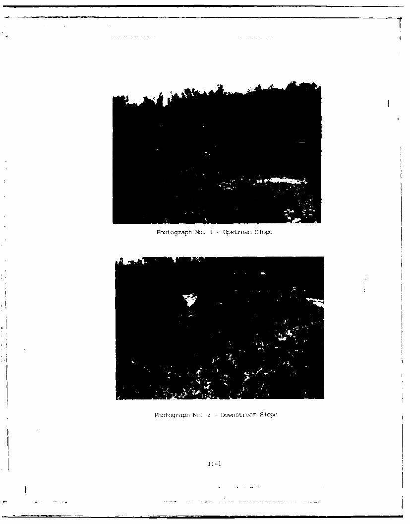
Photograph No. I -Upstream Slope
Photograph No. 2 - lflnstrean Slope
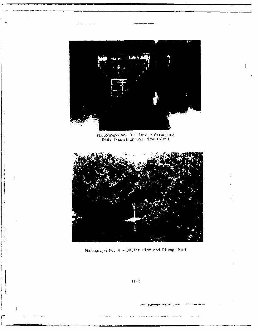
Photograph No. 3 - ntake Structure(Note Debris in Lcw~ Flow Inlet)
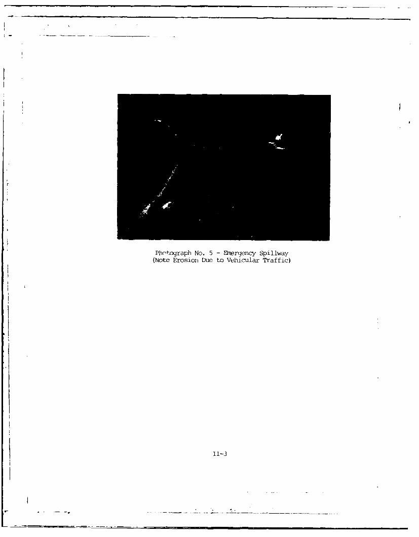
Photograph No. 4 -Outlet Pipe and Plunge Pool
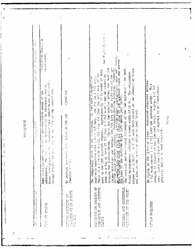
Photograph No. 5 Emergency Spillway(Note Erosion Due to Vehicular Traffic)
11-3

APPENIX III
FIlD O.PSFJVATIO(\S

0 0
rq~
ro 4-1 m
4-'o
0
4-40)
U) r- H 0- m.)U ~C)
4.)' Cfl
9 4 LOC)r- C
- ~ 4-1 C4-! 41U):i 'rl (AZfl z ,'
U))
4--
I-.4
0
0 -10P4. 9- 41
U)i)
'- 1
--4
U
.uf C.
tf) C_-4 4J~
0 0-
r~+I UC) m -
4j -- 1 0~Cr ro+ .- -0 'nU 4j
P - -
Uc-H
C. r r,
r.,
S4 r -
t ri + I4_ -
0 C,. C : 1
I, C),
LrL4
73 En "4.
C,~Z0. I-,4 4C~.
(4 (*.-,~~~ E~ '~C
I),) - C4C

1.4
4-44
-4 C)
(0U .04-8
O44.r-4-
14 4-) 41 Q-
4 4
4-)~
.5 L4 >Ua-
4J4
-4 1.1 r
0
2 ~ . ~-4J 4.
>1 4J
--4 --
or'
0 I
th
0 m
4,
~-4 rI2 m
'144
CL to444
$-. 0
"-- -' Ur. °
II•
14 -4

t5
C-,
M U)Q~ (I)
aJ)
4-1
Q u)
C) U')
71
* rl-
o 0
C) LC
00
UU
F'
II g
H
H
A. :. 2
--I I -~ -
H ~f2-z~ .; 1"
:-~ ~'
~j- IL *~1
HIL
T
I.
-~
Lfl0

.1 ) -i
0. Cii II
tLr)
C)
-4 r
E4 -
1-44
r 4 4-U)C
cnn' 2 s CV,-
ill ti
C) c
r)

247
iti
CT
- 4 I
_ I I I InI
b 0
| |

I I
C)UH
0
U)UU)
U
U .j~J
Qr~~-4 -H
rz
~'
'-- -
-
I- C~'-I
U
4:
I*-~ E-~
U)
z U)
2

LC
a (n
- - -44
F-
i iTi
ATE '"SCHNA B EL ENGINEERING ASSOCIATESDAT 5EET NO -/ OFCONSULTING ENGINEERS
H ,L- fl' DATE JOB NO V
"-A ,jL -4-7f: eA , /
A •- - -- "- - -
--
C AIC.6 4r~ R-E-77rA 4T-.J - Lc'GCNrJL&-
L -)4 Z A - & 1.JC-- ?c j.L IK ,.J L-&cAiC PC . 4c- 6 L3'- - .
Lc-7 -o F- 7 w, -r ,o ?q , (<T
VEZ )] .--,-r AT 70o- -EL.

-APPENDIX IV
DESIN REPORT
r _
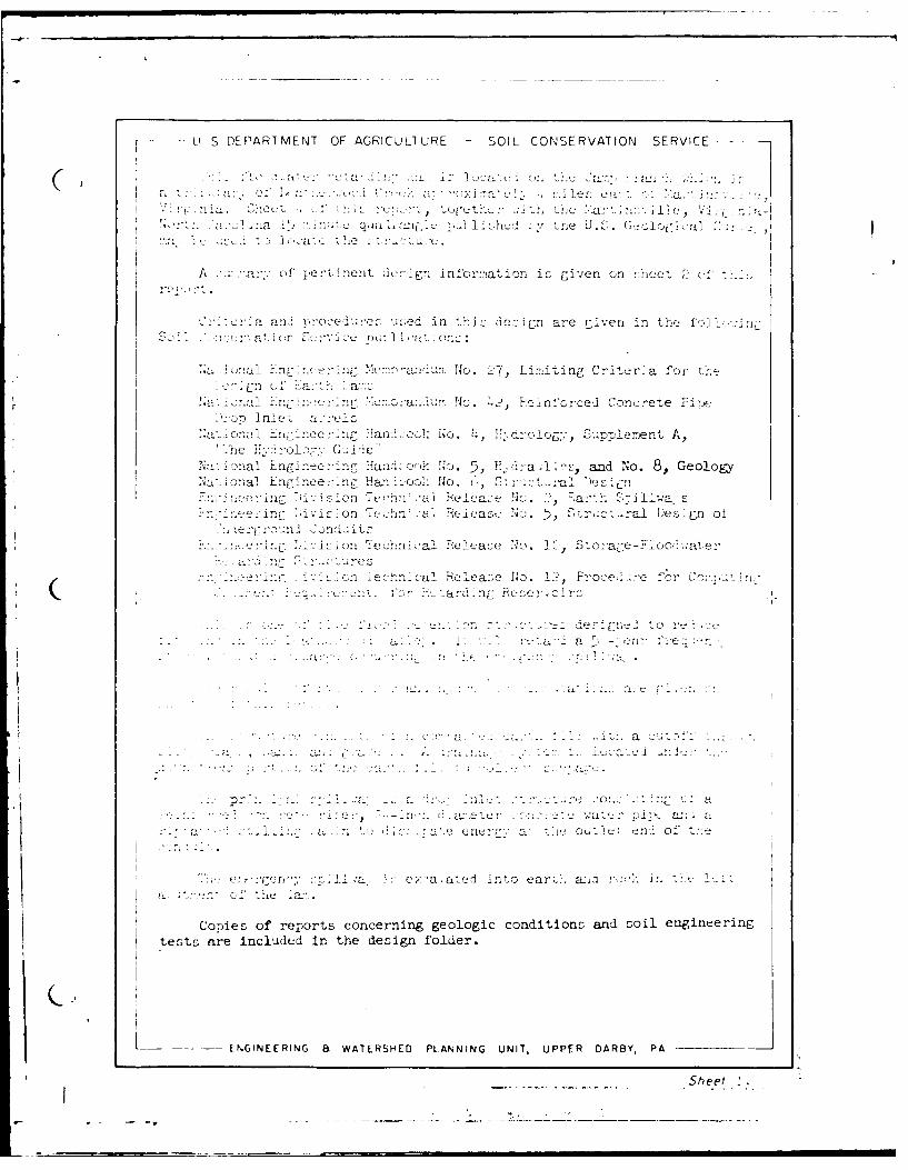
L-' S DE, PART M ENT OF AGRI CU L1TURE SOIL CONSERVATION SERVICE
1~ U o a.' .
A ofc ina: ent Jc-!n mor:%ation is CiX'er on £,,hee _ U
c a an, no' o etdlu!oc uoed in this Je::ign are Liven in thoi f-11-
>&.i on a 1n N 17~anu o. 7,Lirmiting Crito_,r~a for theEc~n u.
!.a fl'n i .On.&c No. ,, enorelConcrete Flo-e
.40 . oni' 3oo4 n an. Jc' No. 4, PiJ~rogy, Supplement A,
N . a 1 nCI .n 2 o nC Han-' honkH. ,E~da lc and No. 8, Geology.O.o: ia! En[7,ine -- nF HaniLao>1- No.(1 5:c:'Ien
- .- a .~l~ No. ., a-U S:ilB1a, s1 0
.'01'eh~a L.-cN.', ou'.-al Des-'gn o!
~ 'a ch Fcl-e1 ea'e No. 10 Soira-e -F-oo?.:ai e:-
c~ne i c a 1Rt ra: ~e INo. 1?, roe,: ':e for onC a'- 'v n nm;1m
2, - . .
.~... .. . . .. c~:[:il 0 no
a~
"o dOu"]U onJi of
''a :0..1 ai.c a t into earci;. ani :'oii-: in0
Copies of reports concerning geologic conditions and soil engineeringtests n're included in the design folder.
(~2
ENGINEERING 8 WATERSHED PLANNING UNIT, UPPER DARBY, PA -
Sheet 2

f' (a- IcC..a V, it 'I
A..* , r . ~ w w vt U n ~ r t a ~ ~ 1 A
2. ~;~;txeCondition III
A. :orJ ai t1. S~c ~. 1..) _______ In.
'n Ri -e r
1. fie _____ F:.
J. Weir iengtli___ Ft.D. Orifice siz2-e _ ____ In.
F. 7iype of energy disssijxtor ____
li E:ii. ir g e u y 5 p 111w"r%A. Wid ti,_____
Side c luje3 ____
T~~~yia oieclsCt~ros Section__
ENIERN 15 WATERSHE PLN IG U IUPE A BP
* -- Ai _____ Sheet_

rc
KnLC,
I"L •
c.
Lz; 0 -,:
-44
-oI-
-4-
i,." .. ,-,-." .
tjl
0)0
I' I:
c
-4 0 W
c i •
t' 4) I)
M 4-)
. _.J . . .. .... . . .. .
Sheet ,
4 -U"" ""_]. . ... - II n •

L. 0 .I ivIcf
FCINEE 14ING(. 8 WALRHFD PLANNING UNIT, UPPER DARB3Y, PA -
F - - --- -
~oI fthe pu: 1 -ritlcrt i -A*o ii thi. n-port Luay :'F I ,a Ifkat OrifLrva [!..'!,A, Sk-i 1 -u'e r, c un
EN ,NfFFNC, a WAT F RSHF D PLANNING UNIT, UPPER DARBY, PA SPe? ,

Yethods and Procedures
1. Pocket penetrometer readings were taken and recorded in the test pitlogs. The abbreviation pp. st:nis for pocket penetrometer. The readingsare in tons per square foot. The moisture of the layer has to be taken intoaccount in estimatijg the bearing strength. When a material is wet it hasnn= leas be;-ing strength th..n when it is dry.
2. The s.al! s&ajplns are not correlated to the test pits in the correlationchart. This is due to the ccplexity of the alluvial soils. But thesessbles are correlated to the different layers in the crosm sections.
3. Soils that wilJ be present in the construction material are classifiedfor easier correlation to the samples. Standard description of these soilsae included.
4. in the lop the unlerlying rock is referred to as granite and coarsegranite. This is for simplification into easily understandable terms.Actually the "granite" is a gneissic syenite. Thia is a rock that hasorthoclase faldbpar and biotite mica as the major minerals. It containslittle, if ar7, quartz. Plagioclase feldspar and muscovite mica arepresent in minor amnounts.
The geologic nwee for the "coars, grained granite* is pegmatite. It iscompzoed of larr'e c. 3 .s5 of )rthoclase feldspar, muscovite mica andquartz. It is more nciJ thxn the local granite. The pegmatite occursas dikes in the na3a of gneIssic granite.
ThA cert-!lne of the der was moved 100 feet upstream. This was toiLnirar that, th,, cut-cff trench -est on a firmer foundation. This r.Ade it
S-na,( VW( 1nvetiiat~c;n ,-n this clam nit-. A a residt of'tnis, tho,.r . ar-, t.'( 11St n' test nit lo's. On the pl.ns test pit numberstnat would nc:z-r ct6J'lna',,,_ th-( !.1fs-rent parts of the dam are not inthem loat ir-n". 3StluKnt test pits wern dui to investigate the geologicconlitions of t.ou, latter i .atins.
\~ 4 ~s ci
10-t..8' 'IA 0-
3DETAILED GEOLOGIC INVESTIGATION OF DAM SITES
GENERALV: rginia _ Henry - L -_.W cns~](:ther'O0o]CTi '
State __(oa nty it. %,4 Sec I R Watershed
Suti are,.sr _ Fund class ST- 8 Uste number Site group . _ Sruc , cias aFP 2., AP I etc I
,n.e jae, bv Mack. T., GcoIQg1 St.[q ,nent used -Cae- backhoe . . . .ate _ 7/( -
rati.ufe and ttleI (Type. SLe, rra e model, etC)
SITE DATA
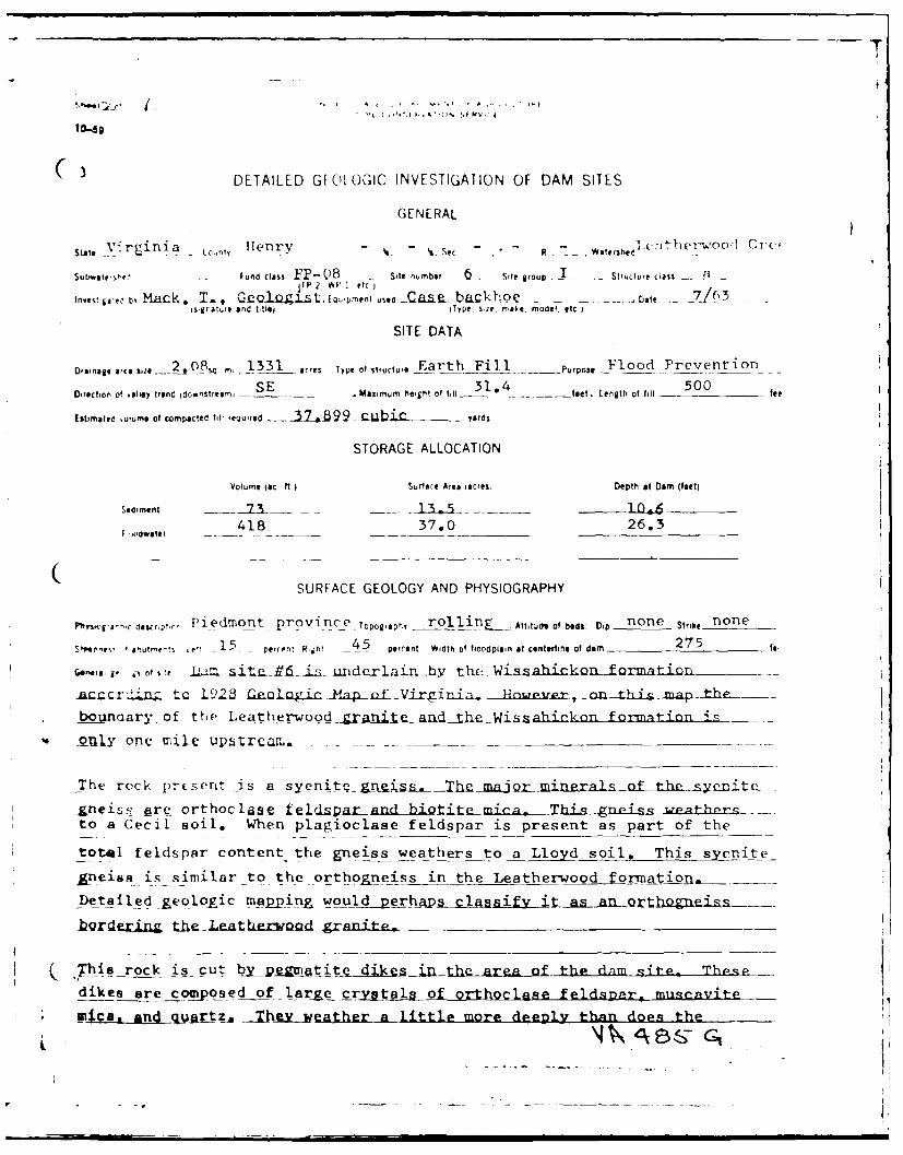
Dinae &,to 20 -- Z, 0-8 , 13 31 acres Type of structure Earth Fill Purpose _Flood -Prev _vnti on-Direction of valley trend idownstreamrn SE Maximum he-ght of til 31.4 feet. length of ill - 500 fee
Estimaied .uume of compacted fill required . _ ZeB99_C bi. C r yards
STORAGE ALLOCATION
Volume (sc ft Surface Aree tacres, Depth at Dam (feet)
Sediment 7____ 1 0_ ] .
Fdwaler 418 5_ 37.0 26.3
SURFACE GEOLOGY AND PHYSIOGRAPHY
Phy.lrg ,C ascrnt.' Piedmont province Toporaplr, rollin _ Atitjdu of beds, Dip none Strike none
S, ., uMeeeS 10!u- 15 peren R,jh! 45 _ percent Width of floodplain at e nterline of dam 275 fi
* Gen . it ot s e li aie V6- i- undarlain hy thi- Wisahion-formatlizrn
Acc cr.Zin t c L.928 f&£ia1Qgic Map -f -Vrii- ibi ptke-r -
__ _%naary of the Lea therwood _Zranit _anAh1.__Wissahickon formtion
4fljy onc mile upatrcaiL.
The rock prEsent is a syenit-_gneigs. fthhe soith-
&neiss gre orthoclase fel daradbit e ~mica- Thi gneic wathrs..to a Cecil soil. When plagioclase feldspar is present as part of the
total feldspar content the gneiss weathers to a Lloyd soil. This syenite
gneiss is similar to the orthogneiss in the Leatherwood formation,
Detafledgeologic mapping would_4perhap~s ssifv it as an orthg n.iss.
12Qrderig theLeather oad gr-n i -e
-This rock is cut bY__pe titSe diesitthe area of thp dnm site. Thuenpdikes are composed of larae crystals of orthoclase feldspar, mugcavite
mias _ a qr tZa _ThWL_weather a little more deeply than does the
_ T
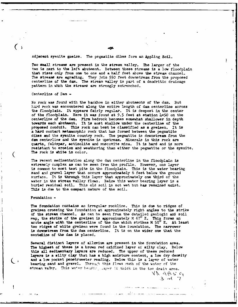
adjacent syenite gneiss. The pegmatite dikes form an Appling Soil.
Two small streame are present in the stream valley. The larger of thetwo is next to the left abutment. Between these streams is a low floodplainthat rises only from one to one and a half feet above the stream channel.The streams are agrading. They join 550 feet downstream from the proposedcenterline of the dam. The stream valley is part of a dendritic drainagepattern in whch the streams are strongly entrenched.
Centerline of Dam -
No rock was found with the backhoe in either abutments of the dam. Buthard rock was encountered along the entire length of dam centerline acrossthe floodplain. It appears fairly regular. It is deepest in the centerof the floodplain. Here it was found at 9.5 feet at station 4+50 on thecenterline of the dam. Firm bedrock becomes somewhat shallower in depthtowards each abutment. It is most shallow under the centerline of theproposed conduit. This rock can beat be classified as a greisen. It isa hard contact metamorphic rock that has formed between the pegmatitedikes and the syenite country rock. The pegmatite is downstream from thedam centerline and the syenite is upstream. Minerals in this rock arequartz, feldspar, actinolite and muscovite mica. It is hard and is moreresistant to erosion and weathering than either the pegmatite or the syenite.(The rock is white in color.
The recent sedimentation along the dam centerline in the floodplain isextremely complex as can be seen from the profile. However, one layeris common to most test pits in the floodplain. This is the water bearingsand and gravel layer that occurs approximately 6 feet below the grounds,-fae. It is through this layer that approximately one third of thewater in the stream valley flows. Below this water bearing layer is aburied residual soil. This old soil is not wet but has remained moist.This is due to the compact nature of the soil.
Foundation -
The foundation contains an irregular rockline. This is due to ridges ofgreisen crossing the foundation at approximately right angles to the strikeof the stream channel. As can be seen from the detailed geologic and soilmap, the strike of the greisen is approximately M 670 E. This forms anacute angle with the centerline of the dam which strikes M 580 E. At leasttwo ridges of white greisen were found in the foundation. The narroweris downstream from the dam centerline. It is on the wider one that thecentaline of the dam is placed.
Several distinct layers of alluviuim are present in the foundation area.The highest of these is a brown red oxidized layer of silty clay. Belowthis all sedimentary layers are reduced. The upper of these reducedlayers is a silty clay that has a high moisture content, a low dry densityand a low pocket penetrcmeter reading. Below this is a layer of waterbearing sand and gravel. Thro,,h this flows nuch of the water of thestream valMey. This wal-r 4s.rir a-zr thick in the toe drain area.
S~.-7

fram a pegnmatite dilkD that cuts the syenite in this area. At a depth ofgreater than 10 feet in this soil angular sand and gravel size particlesoccur. On the right abutment 800 feet upstream the syenite is within7 feet of the ground surface. Here a Durham soil occurs. This soil typehas a sandy texture. It contains same silt and clay. No rock was encounteredin the borrow area closer than 750 feet to the centerline of the dam onthe right abutment.
(
--- -. --- . . . ,--- li- _ _ _ _

Sclr
LeteIod rnt n
6yeit "'tNh -~gtie
(3tawo aeiawtotaneisl stutr a /
N ),-at//er
Wishco /hs ws
GELOI MA>7TE:RASOMNGST oLFATERWOD Cm l/sp m" -4 , V
te
MAY 55
UNITEO STATZ.L bLPAtR',FNT OF AGRICULTURE
SOIL CONS'l -VATION SERVICE
SOIL SAMPLE LISTSOIL AND FOUNDATION INVESTIGATIONS
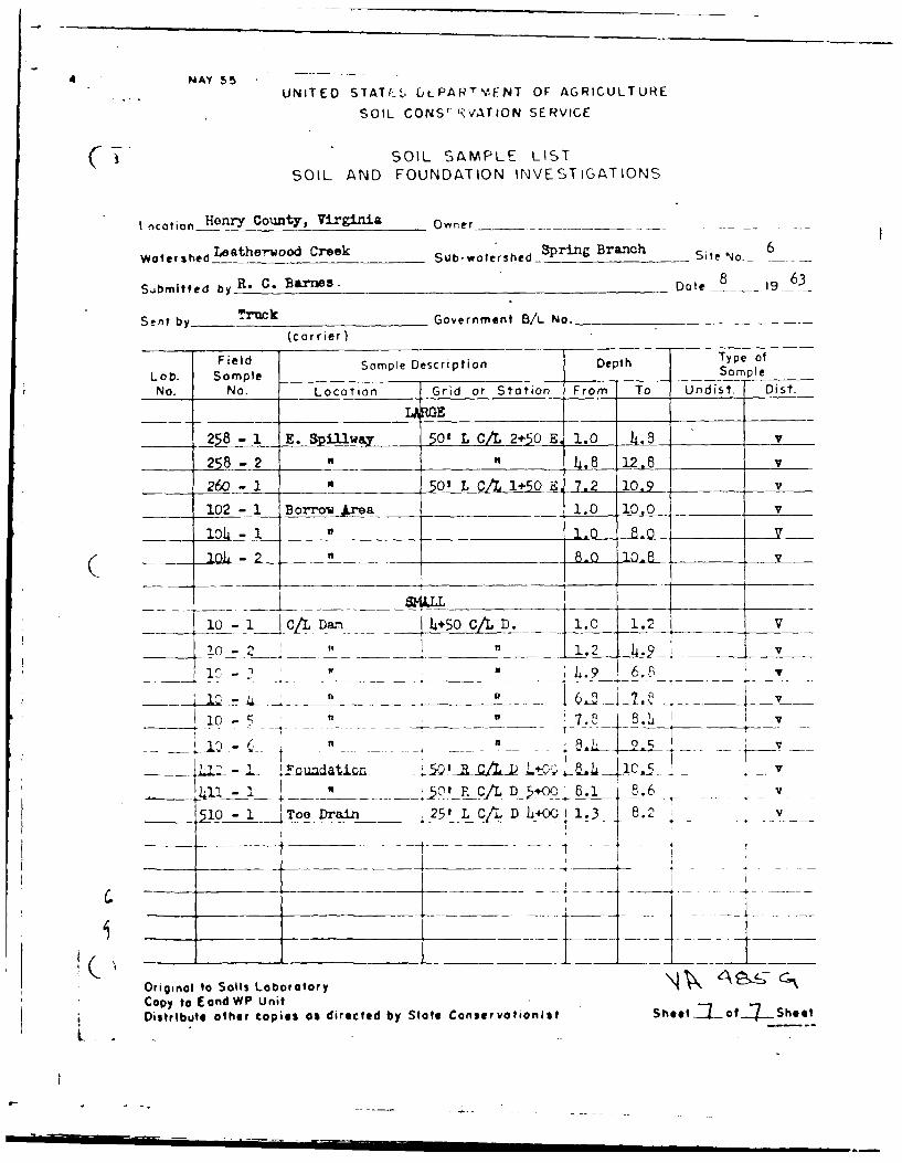
t ocation e County, Virginia Owner_
Watershedl Leathey'wood Creek Sub-watershed Spring Branch Site No- 6
bR. C. Barnes. D 8te_ 19_63Su.bmitted by _______________________________ oe1
Sent by__Trck Government B/L No.(carrier)
Field Sample Description Depth Type of
Lob. SampleS Sample
No. No. Location Grid or Station From To Undist, Dist,
2E8- .. STIu, _ 501 L CA o2+ O .0 4.8 V
258 - 2 _,,_riL12.8 V
260 - I"' L C/11+ E 10.9 v
102 - 1 1.0rea 1.0 10.01 V
104 - 1 81.L0 8
( - 20 2 -2 "__ 8.o0.8 V
-1 c DCIL -- 4+5o c/L D. 1.0 1.2 V
102 1.2 .9 v
.. .A QI? L' " ___ ___I5- ii 1 . 6.5
-V+. -5o, -. c D +, ~8.1 8 .6 _ v
510 - I__Toe Drain _ 25 tL C/LD L+001.3 8.2)___ t - ,
Original to Soils Loborotory \ 4', 4e cCopy to EondWP UnitDistribute other copies as directed by State Conservationist Sheetl----of--- Shoet
1. -
" U-- -r l-.I

DETAILED GEOLOGIC INVESTIGATION OF DAM SITES
I- _____ Virini Cony-er Watershed .Laf.-odCree~b~h -Camp Branch
sit. nu ber -_6 Site group _Stucure class -- a Investigated by T. Mach,_Geoilo ist Il,_ July /_.3(signature and fitlej
INTERPRETATIONS AND CONCLUSIONSMCR Dh-&SRVICE !ISE NLY
1. It i necessary that a cutoff be installe and anchored one foot into bedrock. Thisis to intercept the flow of water through the water bearing sand aznd r~avel presentLn th- flcoplain. As at least one third or pnossibly two fifths of the water flow_n6dow:ithe va2ley pasoes through this layer, a good cutoff is mandatory.
2. The residual soil 'ong the centerline of the proposed conduit Is fairly hard in place.Although the downstream portion of the proposed conduit will not be on rock, use canbe 7ade of this firm scil to support the cradle.
3. The proposed conduit can be moved to the right to lower the rockline. The slope of therockiine in this area of the left abutment is 1 to 6. But the white greisen rock hereis fractured and can probably be ripped with heavy machinery.
L. The toe d4ain area ccntaiis a layer of water-bearing sand and gravel (DS 510-1). Thislayer allows free passage of water through much of the floodplain. But at some placesthis flow is stepped in the toe drain area, TP 303 locate' 65 feet downstream from thecenterline of the dam. sows the water-bearing sand and grave' to be absunt. Thisirfcrmnation can be taken into consideration in design of the toe drain.
A layer of soft, mcist gray clay (cl) blankets most of the founJation of the dam. Itccc,-u from aT :roximately two to seven feet helcw the ground surface. As removal ofthl_ frcr. te foundation will be expensive, the desirn of the dam should be adapted tothnt con itlon.
*. F'r. - -ya7naton of itr surface U-e rock in the emergency Fpillway is thought to berl'. ! with neavy machinery. However, this oinion is from the surface conditionsrf *7. r:Ck an'd may no+ be true at depth. At least 10 feet of this syenite rock has
"c :" r -c. ve .
A Y el' y 30 percent of the borrow material for the dam will come frcm the Lloyds I i. trie emerency spillway. Of this material the most suitable for construction
-t :eJ Iay that is closest tc the surface. The next most suitable is they- - .:t lel--w the clay. The poorest construction material in the area is the
7- a material below the silt. This is to go only on the downstream slopes.
-. 4 a .n t e borrow area should becnly down through the red silt horizon.S ,:-,wi mica material is to be discouraged unless it has to be removed as in
-u-o: s,.Ilway. The Uppling soil of the borrow area is fairly good construe-- -:. t R.a a low clay content. But this clay may be enough to tie the sam
*- A ,, ii ostruction material could be made by mixing pan load for pan. .Y. lhr.zonr clay with wiite C1 horizoi,'.ppling sand. The Durham soil is
- -o . , ,-rruw arma. It is silty and sandy. Compared to the other-t forms a fair construction material.
- * - .,-r, borrow material available in the right abutment. But of theS.. , .od clay material for the cutoff and core is scarce.
...... ii I
APPDIX V
STAB LL I VY W1%TA

UNI'r-1D S1..\TS (;(iVFRNMEZN T
TO R. C. Bar:,.ts, St.ate Cc,-ze--vazior. DATE: Gctcber 20, )CEan6~,E~r, SCS, Ihr.,Vir :h:,a 23-240C
F R OM Ec S. Decker, Head, MolIecm- Laoratoryl,
SCS, Lincoln, N~rso l -
sUJc:ViJrginia 'vT-08, Leathe--v.c. C--- -, Ste No.
2. Fin SCS-5' Tra-:a _--- -- ,3- 3 sheets.3 1~o SC~ 2 Co- PtI~ezstance Report, 6 sheets.
5. F-n SCC S-357, S'---a' - ty Analys is, 1 sheet.C -. st ..a. c..l Pla a:-.
c.ad v%, 4 a as describel 4n the Coicj'
L. -..- ac fc.0, -fr&: -c valey aliuviuz na a 10-.of5 ~cf 2. 1- 7 feet, ti- low 'DIastjit
i.'T U a ac.~-' f.-.: [1.3 to 78 P-c-f. ?.aZonedutc a'Ca a.' soit. 0ne ,'Ln-iy stzt:, srela'tively den-se. A test
inthisn zone s-howed an in,-place density of 118 p.c.f.
( 2 R-i. C. pre -1/06
Recy S. DeclfelrSubj : Virginia WP-08, ~hroaCreek', Site o.6
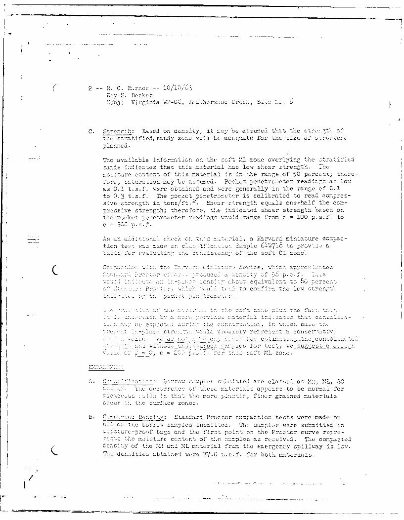
C. Strerth: Ba-sed on ac-nsity, it n~ay be- assuzsed that th'e te.th fthec s-.ratificl, sanay zunc, will be: adcua-te for the size of s,-,;- , ,
Planned.
Thie availz-ble ir-forma-icn oni the socft ,L z one overlying the trtf csands :rndica-zes that th1-is material has low shear strengt h. Tne
z~ostrecontent of this material is in the range of 50 perce-nt; there-fore:, satusirtion may Ie ass,-zned. Poclk-et nenetroneter readi.-gs a.- low
as 0.1 t.s.f'. were obtained and were generally in the rre cf C.1to 0.3 t-s-f. Thle -oocket nenetroeter is calibrated to read cona;res-sive strength in tons/ft.2 '. Shea-r strength ecu,,als one-half ',he c_pressi've strength; therefore, the in~dicated shear strength based onthe po,,ckct -renetrometer rea-dings would range from c =100 p.s.1'. toc 30. .S. f .
AF. an add--iinal check o~n tis material, a Earva ,rd mirniature cozntac-tionteeswasmacr on ~as: icsionLamle 6 w7-,8 to, provocea
fr evfo .he soft CL zone'.
c ecu ,va10..Z SOr ceL 0 - .conir the low str E:n:t
e ~i comsiucsh ca---s e 1 roLsuu rej-res:2nt a coie
j ' n:D7 :or esti-.at7n -tn, conzsolia
I I u u,--n. 5 :.:crj for' t(,t we sueoct ac-, c f. tc: zone.
C,. 1_4e 7 .rr3w smIs s , 4itted are classed as M:7, ML, SC1' crsrrccco:ths mateL;l apiocars to be norm-al for
. i ntn~a- th.e more -,Iastic, finur grained materiulsc, u tr '-, fzice zor~es-.
B. Cv t. -t:Stasndard Proctor compaction tests were m-ade on1C,;, tnc c ate subm-.itted. The sampls were sutmitted inmostr-toh a-%; andi thie firsLt point on teProctor curve rere
ren: hemoIsturecorsn of the ,-.amnles as receive-d. Tne compactea-3dernsi y of the c and '.L m:aterial from the emergency ,-sp.ilway is low.7The decte bta ±ined wt-re- 77.0 '-c-f-.'fOr both materials.
3 -R F. C. Rcirnes 1- 0/110/63Rey S. Decker
Sb:Virg7iria WP-08, Leathur-sood Creek, Site INo. 6
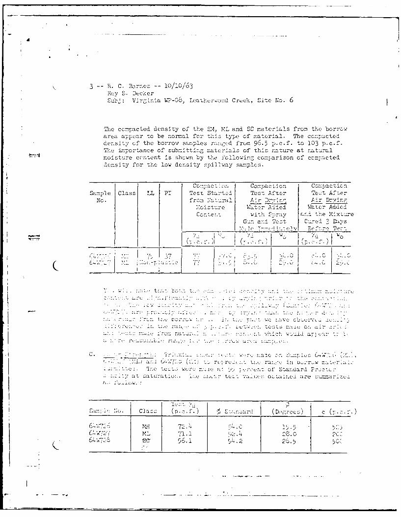
The contacted density of the EM, ML and SC materials from the borrow
area a-=,ear to be normal for thi.s type of material. The cc.-szc ted
dernsitv of the borrow samples ran~fed from 96.5 P.c.f. to 103 p.c.f.The Lnport ance of subm-itting ma-Lerfils of this na~ture at',tra
moisture ceatent is shown by the following comparison of ccms7acted
density for the low densit l lla amls
Co a ci C om a czi.On C3.nmoaction
Sample Class LL PI TesT Sts-.:tcd Test After Teot Aft-er
No. frcm 1,trl Ar r.i. Aimr Dryinfr
i stur e a.r Pa de d Water Added4
Conter.i with Stray arnd th,.e itr
Gu-n and Tes-t Cor, el 3 Da,'s
_____________ ~ 4,- "?~ T-i'e v croTt
7 7
wc c'--, w
iC OL~~iflC. ar ,
a., (D.,e s
_____________________ ______________ _____________________ ________________________ _____ 5 -5____________________________________
(.A7ML 71.1 (12.0 2CC)
6 56. -r. - - .5__ -

( 14 - C. Barnes -- 10/10/63-Be':: S. DeckerS"., jj: Virginia iWP-08, Ict;rcaCi-e1-, Site I~lo. 6
Thec test values are consideril representfutive and are stsatrdesir values for the embarcr. materials.
SLOPF S.' niLiIY
Thie s-.a it of te p'cnoca n was checked for twc cond~ition,;.one alysis Considered, the &-~~ lone with a full, - ce
phetc line. For L..ic; cc.u di er analysi.s was made on a 2 1/2:1downstre=- slope with --t dox.in, c. 1"e factor of safety obtairnod for a.hc~nogeneous fill of ,.e lowest Ztren---i materials tested (64,,727) was 1.43.The unstre - slope proposed is 2 1/2:1 ovcr 3:1 with a 10-foot e. Thfactor of safety for the upstream slore iurder full drawdourn wouldI beSl ",Il I g-her than that shon for t~l downst.ream slose.
The 0 rj nayss c a a tics natof
src-'- -.- ct- . of'~ 0, c .. '. p.c cb as eTh iins o: Lt. "' Zas.- f
c,:'. ar
r2 2u 1.
.us C,. a,.
r~ L
A~". ~ /0 2 ~iL.t~~ ~r m..t
B . C rre.:T,, e cat . a . to n bo 'omck'tru} ..AJr sestlo Ao- Uof5 fect il, st"gc 'LcJ

( 5-->.C. >rr-10/10/63
reVu-k Si. NeOr .
hetrerA- choQ~ be baickfille-d wQt- ML or SC material li keS GcIie 6Cvj2 and C4v(3. :. t ktl .soals bLe comnTacted t
-' of5% of Su-and::rd ?nzx
C. PiialSiwv:2. urscpiialsllyinthe vilcini tyof~oaio 2<5 n btorloutonfrom a founr.dationGr sztzrndplo--t,
th, an the abaundurned locat-o a7-:t Sta ti-on 3+50.
tithe Staztion 2+75 loa~nthe con: duit will be tedded in be:--drckth--roughout mozt of its 4et .At the p-roposfed grade the upp.er endan-d thNe locwer en-d will not* b-e on.- bedrock . It may be possible,ho's,.ever, to sk'ew the cnutor shift. it more to the left and obtain
feter :a.nUat on conditon i. - n tevicinity of thle ris-e.
D. D1i :.r-, 7n ert ;a:~nSome zones, it- is log~ea.. .- Wr. elage mnay be expected to
*~~~~~ 7:. -. . . . . . :cf0 s we I as in the abut -~. ot c~somin nedrook. We suggrest
- .. -. .~ :.:>tfor fona~nseep.age
- U.6 ama exten- ati
.of ni.dctuf~ out r6.0 feOet is- . . .:. n M ,- rno et 5 f eet is
',LudS mater4-ian tecnecr UJ SM in the downsZ; t r
.u . a -- inur .. rvng-th and nay be used,zt::. t2 n te , rweve -', piace tnt in the downstream
0Wu.. 1cd Iac LOt co....xol of toe phreatic line within
All maeil hudbe plcdat a milimum Of 95% of Starndardrrocto:r densi;-ty wi-th the- mci 1sture content conitrolled slightlyon.- thec wet side of oti~

!I - . C. I-
R e v ~* ,, , 'e7. 5 D t'c w r
2. L're ."The follow.Irc aler.tt lope digsare sucuested:
a. If'th low strtc so o' L raterial ir. the fouruati:na~e CZQ~U. T: .12 1/2:1 over 3:l upstream slope
w~t a 10-fr- 2 - /2:1_dcownstream loehavesc- acto ry !au c o c, of and are rcmeaa
b. Ifth low ror Zr. -' c' M'L are stremoved from toe
Lou :~atio: we . -, U e berm width be increased to2' ee or. te.>cand th,-at a 15-foot ben--n be
a....~ totoe s 'a about elevation 711.
3. "' :: ro.An ove -' all: tor of 1.5 feet over the flood4-
~esr a -.- ' -satefor residual consolida-
t woans ovov.

U. S. NilpimII Of ARICU WE17M Q OI L Cb?.:U I k V ATIU'~ IC
/SOIL !.EC1A1'ICS LAPORhTORY*SU:2!ARY - SLOPE STABILITY AN~ALYSIS
Hec,*J cf Anal~ysts
>L:caUtf i on_ _ _ _ _ _ __ '_ _ _ _
C.)
i fl i t i~ on opt. --,at OP.._____ _ 0; t sdt . opt sat . O
; -. -P i, I_ _ _ _ _ I_ _ _ I _ _ I_
.-- 4 0 ___ __ ___ ___ ____ __K
4- _ _ _ _ _ _ _ _ _ _ _ _ _
Tr S
-7i

I I .1 I
-- /2
/
-- /~ /7 Vt
- I 'A-N
NK N
'C' - -'
,.'' ~:Y I'/ /x /L. \
-~ -
V ----- (-/ 7 il
// -
-FC -' -
C.
5- --
I /K
~ -
1
'N
K V
I I I

7 ;E I )iX', V.I - ]o :E} :HJ-2ZES
1. P~onmin d GuicieAines for Safety lnscct-ion of Duis, FX-';,UtiTit
of Ar y, Office of the Chief of Engineers, 46 pp.
2. Dsin of S Il Damns, U. S. Department of Interior, Bureau of
Recclaution, 1974, 816 pp.
3. Gn ]),xV of the Sno., C-rek, Martinsville East, Price and Spray
Cuadrangles, Virginia by J. F. Conley and W. S. Henika, Virginia
Division of Mineral Resources RPejxrts of Investigations 33, 71 pp.
4. HEC-1 Dam Break Version, Flood Hydrograph Package, Users Mnual
for Darn Safety Investigations, the }Hydrologic Engineering Center,
U. S. Arri, Corps of Engineers, Setpxunber, 1978.
5. ]drcomc terological Rcrxrt No. 33, U. S. Departartnt of Ccmerce,
W iatber Bureau, U. S. LD-partnn-nt of Ar5rr,, corps of Engineers,
Wishincrtn, D. C., April, 1956.
(. Tr.mhnica] Pa<cr Uo. 40, U. S. D[zprtnrint of Coir i rce, Weather
: l ..... . n ,: ii-- -- , C ., II, 1901.

DTI