Embed Size (px)
Citation preview
MOVOTEC®
Dual-Drive “Bolt-On” Lift System Manual
by
Copyright © 2013 by Suspa® Incorporated
All rights reserved. No part of this manual may be reproduced or transmitted
in any form or by any means, electronic or mechanical, including photocopying, recording, or by any information storage and retrieval system
without permission in writing from Suspa® Incorporated.
01/11/13 670- 00021A
1
1.0 Table of Contents 2.0 Introduction ................................................................................................................. 2 3.0 Safety Instructions ...................................................................................................... 3 4.0 How it Works............................................................................................................... 6
4.1 Extension Cycle: ........................................................................................................ 6 4.2 Retraction Cycle: ....................................................................................................... 7
5.0 Unpacking Instructions .............................................................................................. 7 6.0 Lift System Specifications .......................................................................................... 9
6.1 Lift Cylinder Specifications ..................................................................................... 10 6.2 Motorized Pump Specifications............................................................................... 10 6.3 Motor Controller Specifications .............................................................................. 11 7.1 System Component Placement ................................................................................ 13 7.2 Motorized Pump Installation ................................................................................... 14 7.3 Motor Controller Installation ................................................................................... 15 7.4 Low Profile Switch Installation ............................................................................... 16 7.5 Motor Controller Cable Connections ...................................................................... 16 7.6 Lift Cylinder Installation ......................................................................................... 18 7.7 Hydraulic Tubing and Cable Management .............................................................. 22
7.8 Workstation Leveling .............................................................................................. 22 8.0 Operation Instructions ............................................................................................. 24
8.1 Before Connecting to Power.................................................................................... 24 8.3 First Operation ......................................................................................................... 25 8.4 System Extension Cycle .......................................................................................... 26 8.5 System Retraction Cycle ......................................................................................... 27 8.6 Duty Cycle Monitoring ............................................................................................ 27 8.7 Deceleration Zone .................................................................................................... 27 8.8 System Reset Procedure .......................................................................................... 28
9.0 Troubleshooting ........................................................................................................ 29 10.0 Inspection and Maintenance .................................................................................. 31
10.1 Changing Load Conditions .................................................................................... 31 10.2 Motor and Load Alignment ................................................................................... 31 10.3 Contamination ....................................................................................................... 31 10.4 Power Cord and Hydraulic Tubing Damage ......................................................... 31
11.0 Warranty ................................................................................................................. 32 12.0 Replacement Parts .................................................................................................. 33 13.0 Optional Accessories and Enhanced Capabilities ................................................ 33
14.0 Disposal .................................................................................................................... 33
15.0 Contact Information ............................................................................................... 33
01/11/13 670- 00021A
2
2.0 Introduction
Thank you for purchasing the Movotec® Dual-Drive “Bolt-On” Lift System.
The Movotec
® Dual-Drive “Bolt-On” Lift System is a motor driven single-acting fluid
displacement lift system. The “Dual-Drive” was designed specifically to raise and lower large workstations and machine bases. It includes two of our standard motorized Movotec
® E-Drive “Bolt-On” lift systems. Both lift systems are actuated simultaneously
by linking the motor control boxes. The motor controllers keep the workstation level during extension and retraction cycles even under unbalanced load conditions. The Movotec
® Dual-Drive lift system can be configured to drive up to eight lift cylinders and
is capable of lifting up to 2000 lbs. (907 kg). Movotec
® lift systems are subjected to life cycle testing on a regular basis. The tests are
performed in a temperature and humidity controlled environment under full system load conditions. Movotec
® lift systems perform consistently well in this controlled test
environment. However, due to the wide variety of possible lift system applications and operating conditions, Suspa
® does not warrant that any particular lift system is suitable
for any specific application. It is the responsibility of the person who specified the system to determine its “fitness for use” in the application, through testing and analysis, to ensure safe and reliable performance. A complete statement including the terms and limitations of the Movotec
® Dual-Drive “Bolt-On” Lift System warranty can be found in
Section 11.0 of this manual. Movotec
® lift systems are assembled and subjected to a full function quality test before
they leave our manufacturing facility. Suspa guarantees products are free from material and manufacturing defects, but cannot support the warranty for our products if they are altered, misused, misapplied, or abused in any way. It is the responsibility of system installers, users, and service technicians to read and carry out the instructions in this manual correctly to prevent these potentially unsafe and unwarranted occurrences from happening. Thank you again for purchasing the Movotec
® Dual-Drive “Bolt-On” Lift System.
Suspa
® Incorporated
01/11/13 670- 00021A
3
3.0 Safety Instructions READ THE INSTRUCTIONS IN THIS MANUAL BEFORE ATTEMPT ING TO INSTALL, OPERATE, OR SERVICE THIS PRODUCT. FOLLOW THESE SAFETY INSTRUCTIONS AT ALL TIMES.
This manual contains safety, installation, operation, maintenance, and user service instructions for the Movotec
® Dual-Drive “Bolt-On” Lift System. Suspa
® Incorporated is
not responsible for any alteration, misuse, misapplication, or abuse of this product resulting in property damage, personal injury or death.
FAILURE TO FOLLOW THE INSTRUCTIONS IN THIS MANUAL COULD RESULT IN FIRE, PROPERTY
DAMAGE, ELECTRIC SHOCK, PERSONAL INJURY OR DEATH.
If you have any questions about the use of this product, the safety practices outlined in this manual or would like a print copy of this manual, please contact: SUSPA
® Incorporated
3970 Roger B. Chaffee Drive SE Grand Rapids, MI 49548-3497 Phone: (616) 241-4200 Fax: (616) 241-4347 www.suspa.com
VERIFY SYSTEM SELECTION. Before the installing or operating the system, please review the application to confirm that the correct Movotec
® Lift System has been
selected. Pay particular attention to the load capacity and adjustment range ratings listed on the orange pump warning label.
HANDLE COMPONENTS WITH CARE. Do not handle system by the motor cables, power cords, or hydraulic tubing. Keep motor cables, power cords, and hydraulic tubing far from heat, sharp edges, and moisture. If motor cables, power cords, or hydraulic tubing are damaged, discontinue use and have the suspect component replaced immediately. Do not ever attempt to repair a damaged motor cable, power cord or hydraulic tubing line. VISUALLY INSPECT COMPONENTS. Before installing and operating the system, inspect all components for any damage that may have occurred during shipping and installation. Do not attempt to disassemble system or system components for any reason. If a defective component is found, contact Suspa
® Incorporated for repair or replacement.
01/11/13 670- 00021A
4
USE OF TRAINED AND QUALIFIED PERSONNEL System installation, operation, and repair should only be done by persons having sufficient knowledge of the lift system and the contents of this manual. In addition, they must have an understanding of all warnings and precautionary measures noted in these safety instructions. Furthermore, these individuals must be trained, instructed, and qualified to switch electrical circuits and equipment on and off in accordance with applicable technical safety regulations. AVOID HAZARDOUS ENVIRONMENT. Do not operate the system outside. Do not expose the system to damp or wet conditions. Avoid any chemical or corrosive environments. Do not operate the system in the presence of flammable solvents, propellants, and/or explosive materials (i.e. gas, vapor, dust, etc.) Avoid temperatures outside of the system rated operating temperature range 41° to 113°F (5° to 45°C). Do not subject lift system components to vibration and/or impact load conditions. INSTALLATION SAFEGUARDS. Do not use the system for any purpose other than its intended function. Before operating system, make sure that the workstation has a minimum clearance of 2 in. (51mm) from any other object or structure to prevent pinching or crushing hazards. Do not allow wall, cabinet, electrical lines, hydraulic or pneumatic lines, or any other fixed structures to obstruct the movement of the workstation during operation. KEEP CHILDREN AWAY. It is not recommended that children operate this electrically powered lift device. If this device is used by or near children, close supervision is absolutely necessary. OBSERVE DUTY CYCLE. The term duty cycle refers to the amount of time that a motor or system is in motion versus the amount of time that it is resting. The Movotec
®
Dual-Drive “Bolt-On” Lift System is not designed to operate continuously without rest. It is designed for intermittent use only and is rated for a 10% duty cycle. This means that if the lift system is in motion for 1 minute, it must be at rest for at least 9 minutes before the next operation. It is also important to note that the maximum system on-time is 1 minute. To avoid damaging the system, the duty cycle must not be exceeded. Motor surfaces can become warm after extended operation that exceeds the duty cycle. Provide adequate ventilation to allow heat dissipation from within and around lift system components. USE OF ACCESSORIES. Use caution when routing extension cords. Do not allow cords to become pinched or stretched. Avoid positioning cords where they can become a trip hazard. Use only spare parts and accessories authorized or supplied by Suspa
®
Incorporated. Do not replace or replenish lift system hydraulic fluid unless the fluid is supplied by Suspa
® Incorporated
.
DO NOT INSERT OBJECTS. To reduce the risk of fire or electrical shock, do not insert any objects into the system when powered.
01/11/13 670- 00021A
5
MAINTENANCE SAFEGUARDS. Prior to performing any maintenance or service on the device, remove the load from all lift cylinders and unplug the motor controller from power source. The workstation or structure that the lift system is attached to should be stabilized to prevent personal injury or property damage during maintenance or service procedures. RETRACT SYSTEM BEFORE MOVING. To reduce the risk of property damage and personal injury, always retract the lift system fully before moving the equipment. UNPLUG BEFORE CLEANING. Retract the lift system, unplug the motor controller from power source, and allow the system to cool before cleaning components. Clean system components with a mild soap and water-damped cloth. Do not use corrosive cleaning agents or high pressure wash systems to clean lift system components. Make sure system is clean and dry before plugging into power source and operating the system. SAVE THIS MANUAL FOR FUTURE REFERENCE.
01/11/13 670- 00021A
6
4.0 How it Works Movotec
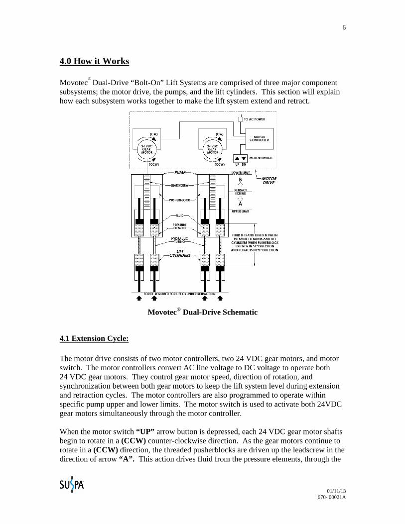
® Dual-Drive “Bolt-On” Lift Systems are comprised of three major component subsystems; the motor drive, the pumps, and the lift cylinders. This section will explain how each subsystem works together to make the lift system extend and retract.
Movotec® Dual-Drive Schematic
4.1 Extension Cycle: The motor drive consists of two motor controllers, two 24 VDC gear motors, and motor switch. The motor controllers convert AC line voltage to DC voltage to operate both 24 VDC gear motors. They control gear motor speed, direction of rotation, and synchronization between both gear motors to keep the lift system level during extension and retraction cycles. The motor controllers are also programmed to operate within specific pump upper and lower limits. The motor switch is used to activate both 24VDC gear motors simultaneously through the motor controller. When the motor switch “UP” arrow button is depressed, each 24 VDC gear motor shafts begin to rotate in a (CCW) counter-clockwise direction. As the gear motors continue to rotate in a (CCW) direction, the threaded pusherblocks are driven up the leadscrew in the direction of arrow “A”. This action drives fluid from the pressure elements, through the
01/11/13 670- 00021A
7
hydraulic tubing, and into the lift cylinders causing them to extend. The gear motors automatically shut off once the programmed pump upper limit is reached. 4.2 Retraction Cycle: (Refer to Movotec® Dual-Drive Schematic on page 7) When the motor switch “DN” arrow button is depressed, the 24VDC gear motor shafts begin to rotate in a (CW) clockwise direction. As the gear motors continue to rotate in a (CW) direction, the threaded pusherblocks are driven down the leadscrew in the direction of arrow “B”. As long as there is sufficient load on the lift cylinder piston rods, the fluid in the lift cylinders flows back through the hydraulic tubing and into the pressure elements. The gear motors automatically shut off once the programmed pump lower limit is reached.
5.0 Unpacking Instructions The system comes packaged in a cardboard carton. To unpack the system:
• Check the carton label to confirm that you have received the correct system; open the carton and remove packaging material.
• Carefully remove the system from the carton, and verify all components are
present (reference chart below), and that the correct lift system was received.
Do not handle the lift cylinders and motorized pumps by the hydraulic tubing. Incorrect handling of hydraulic tubing could weaken the tubing material and system tubing connections.
DAMAGE TO TUBING OR TUBING CONNECTIONS COULD CAUSE FLUID LOSS AND UNCONTROLLED DESCENT OF THE WORK-SURFACE RESULTING IN
PROPERTY DAMAGE, PERSONAL INJURY OR DEATH.
01/11/13 670- 00021A
8
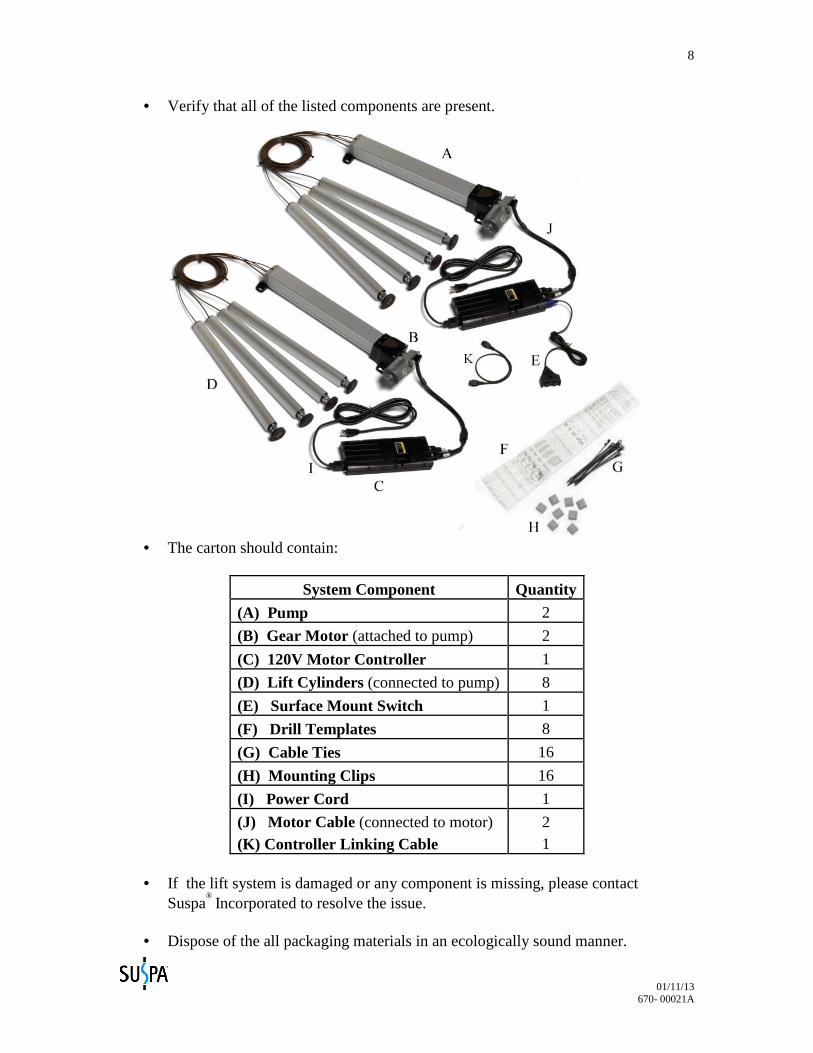
• Verify that all of the listed components are present.
• The carton should contain:
System Component Quantity
(A) Pump 2
(B) Gear Motor (attached to pump) 2
(C) 120V Motor Controller 1
(D) Lift Cylinders (connected to pump) 8
(E) Surface Mount Switch 1
(F) Drill Templates 8
(G) Cable Ties 16
(H) Mounting Clips 16
(I) Power Cord 1
(J) Motor Cable (connected to motor) 2 (K) Controller Linking Cable 1
• If the lift system is damaged or any component is missing, please contact
Suspa® Incorporated to resolve the issue.
• Dispose of the all packaging materials in an ecologically sound manner.
01/11/13 670- 00021A
9
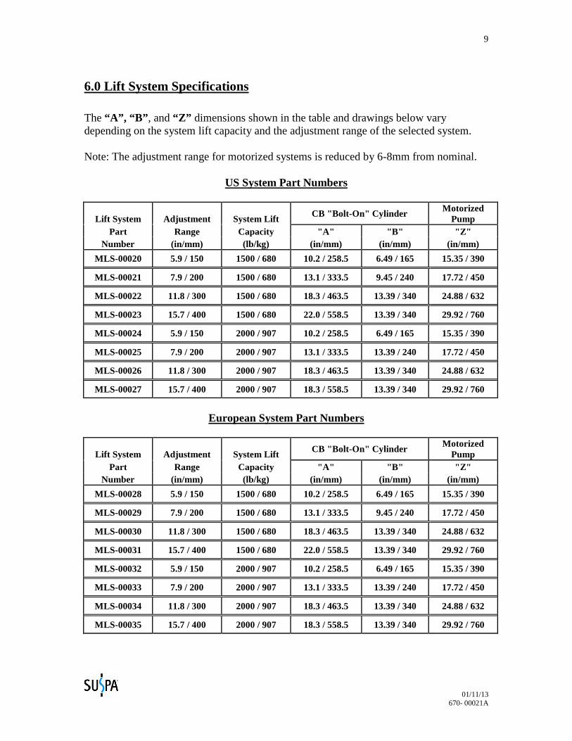
6.0 Lift System Specifications The “A”, “B” , and “Z” dimensions shown in the table and drawings below vary depending on the system lift capacity and the adjustment range of the selected system. Note: The adjustment range for motorized systems is reduced by 6-8mm from nominal.
US System Part Numbers
Lift System Adjustment System Lift CB "Bolt-On" Cylinder Motorized
Pump Part Range Capacity "A" "B" "Z"
Number (in/mm) (lb/kg) (in/mm) (in/mm) (in/mm)
MLS-00020 5.9 / 150 1500 / 680 10.2 / 258.5 6.49 / 165 15.35 / 390
MLS-00021 7.9 / 200 1500 / 680 13.1 / 333.5 9.45 / 240 17.72 / 450
MLS-00022 11.8 / 300 1500 / 680 18.3 / 463.5 13.39 / 340 24.88 / 632
MLS-00023 15.7 / 400 1500 / 680 22.0 / 558.5 13.39 / 340 29.92 / 760
MLS-00024 5.9 / 150 2000 / 907 10.2 / 258.5 6.49 / 165 15.35 / 390
MLS-00025 7.9 / 200 2000 / 907 13.1 / 333.5 13.39 / 240 17.72 / 450
MLS-00026 11.8 / 300 2000 / 907 18.3 / 463.5 13.39 / 340 24.88 / 632
MLS-00027 15.7 / 400 2000 / 907 18.3 / 558.5 13.39 / 340 29.92 / 760
European System Part Numbers
Lift System Adjustment System Lift CB "Bolt-On" Cylinder
Motorized Pump
Part Range Capacity "A" "B" "Z" Number (in/mm) (lb/kg) (in/mm) (in/mm) (in/mm)
MLS-00028 5.9 / 150 1500 / 680 10.2 / 258.5 6.49 / 165 15.35 / 390
MLS-00029 7.9 / 200 1500 / 680 13.1 / 333.5 9.45 / 240 17.72 / 450
MLS-00030 11.8 / 300 1500 / 680 18.3 / 463.5 13.39 / 340 24.88 / 632
MLS-00031 15.7 / 400 1500 / 680 22.0 / 558.5 13.39 / 340 29.92 / 760
MLS-00032 5.9 / 150 2000 / 907 10.2 / 258.5 6.49 / 165 15.35 / 390
MLS-00033 7.9 / 200 2000 / 907 13.1 / 333.5 13.39 / 240 17.72 / 450
MLS-00034 11.8 / 300 2000 / 907 18.3 / 463.5 13.39 / 340 24.88 / 632
MLS-00035 15.7 / 400 2000 / 907 18.3 / 558.5 13.39 / 340 29.92 / 760
01/11/13 670- 00021A
10
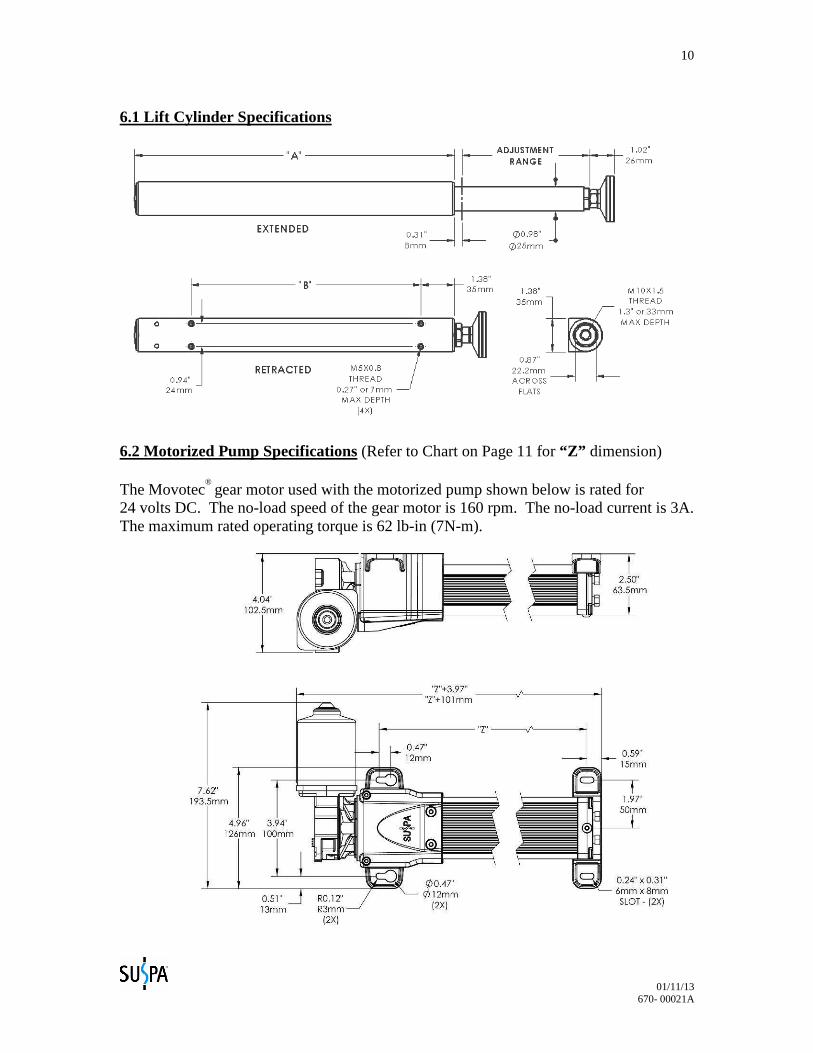
6.1 Lift Cylinder Specifications
6.2 Motorized Pump Specifications (Refer to Chart on Page 11 for “Z” dimension) The Movotec
® gear motor used with the motorized pump shown below is rated for 24 volts DC. The no-load speed of the gear motor is 160 rpm. The no-load current is 3A. The maximum rated operating torque is 62 lb-in (7N-m).
01/11/13 670- 00021A
11
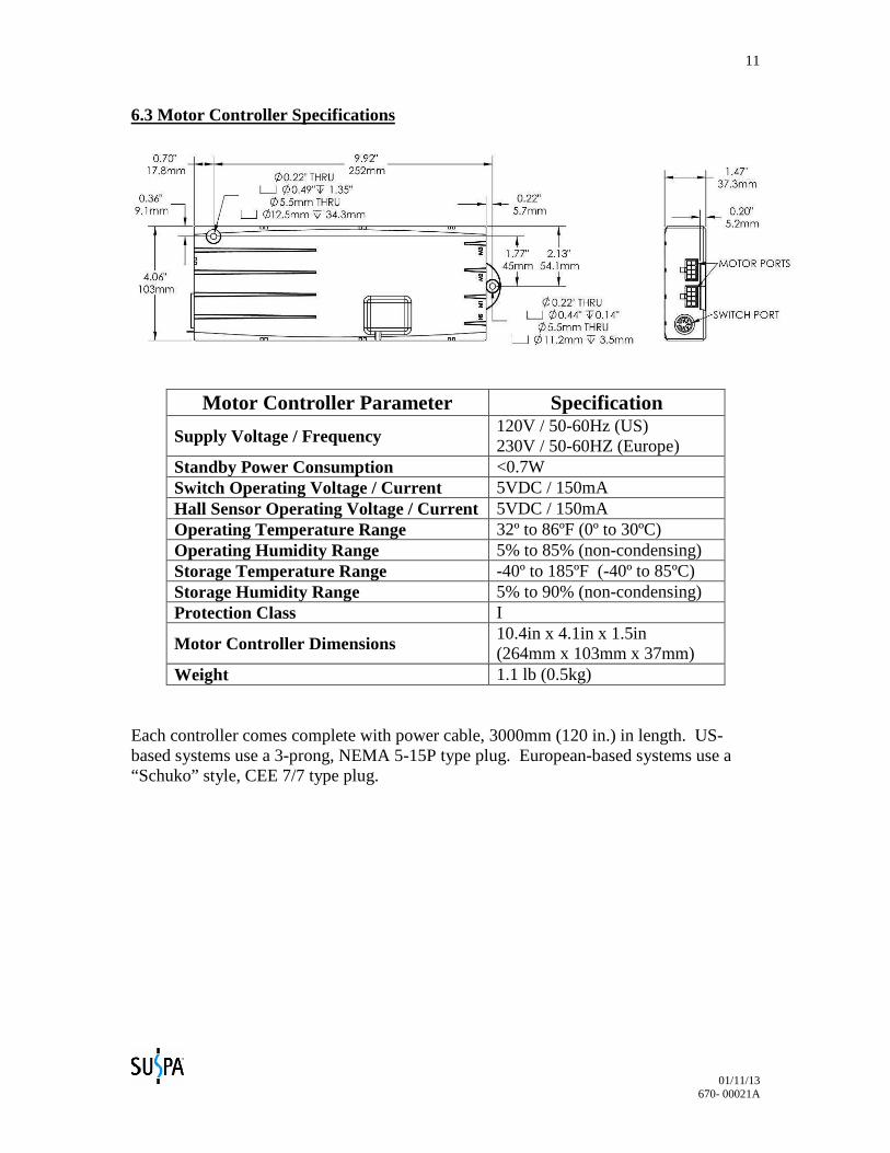
6.3 Motor Controller Specifications
Motor Controller Parameter Specification
Supply Voltage / Frequency 120V / 50-60Hz (US) 230V / 50-60HZ (Europe)
Standby Power Consumption <0.7W Switch Operating Voltage / Current 5VDC / 150mA Hall Sensor Operating Voltage / Current 5VDC / 150mA Operating Temperature Range 32º to 86ºF (0º to 30ºC) Operating Humidity Range 5% to 85% (non-condensing) Storage Temperature Range -40º to 185ºF (-40º to 85ºC) Storage Humidity Range 5% to 90% (non-condensing) Protection Class I
Motor Controller Dimensions 10.4in x 4.1in x 1.5in (264mm x 103mm x 37mm)
Weight 1.1 lb (0.5kg) Each controller comes complete with power cable, 3000mm (120 in.) in length. US-based systems use a 3-prong, NEMA 5-15P type plug. European-based systems use a “Schuko” style, CEE 7/7 type plug.
01/11/13 670- 00021A
12
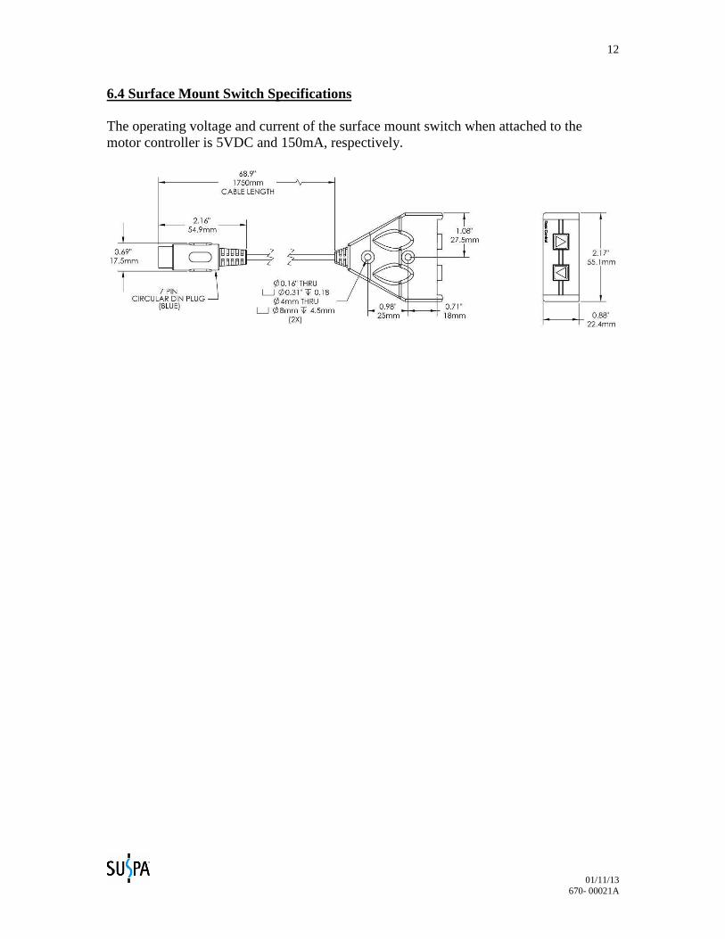
6.4 Surface Mount Switch Specifications The operating voltage and current of the surface mount switch when attached to the motor controller is 5VDC and 150mA, respectively.
01/11/13 670- 00021A
13
7.0 Installation Instructions
FOLLOW ALL SAFETY INSTRUCTIONS CONTAINED IN SECTION 3.0 OF THIS MANUAL BEFORE
INSTALLING THIS PRODUCT. FAILURE TO FOLLOW THE INSTRUCTIONS IN THIS MANUAL COULD RESULT IN FIRE, PROPERTY DAMAGE, ELECTRIC SHOCK, PERSONAL INJURY OR DEATH.
7.1 System Component Placement
There are many system components in a Movotec® Dual-Drive “Bolt-On” Lift System.
Since all of these components are physically linked together with hydraulic tubing and electrical cables, it is very important to make sure that the components are located on the workstation so that everything can be connected safely and correctly.
7.1.1 Motorized Pump Placement - The motorized pumps can be mounted in any orientation, however it is recommend to be mounted horizontally. The motorized pumps should be mounted so that there is enough hydraulic tubing to reach each lift cylinder and enough clearance for the minimum hydraulic tubing bend radius of 2 in. (51mm) to be maintained. Suspa
® Incorporated offers a black
thermoformed plastic motor cover to further protect the gear motors and cable connections from possible damage. The motor cover can be purchased on our website at http://shop.suspa.com. 7.1.2 Motor Controller Placement - There should be enough power cord length to facilitate movement of the workstation without the power cord connector becoming separated from the motor controller during operation. To accomplish this and to ensure that there is enough power cord length to reach a power receptacle, the motor controller should be placed toward the center and backside of the workstation. In addition, the motor controller should be placed so that it is in relatively close proximity to the gear motors. If this is not possible, Suspa
®
Incorporated offers motor extension cables to make up the difference. These cables can be purchased on our website at http://shop.suspa.com. 7.1.3 Switch Placement - The switch should be mounted on the side of the workstation where it is most accessible to the user and so that there is enough switch cable to reach the motor controller. The low-profile switch is one of many motor switch options offered by Suspa
® Incorporated. Alternate motor switches
can be purchased on our website at http://shop.suspa.com. 7.1.4 Lift Cylinder Placement – The lift cylinders should be located on the workstation so that the load on the system is balanced. Lift cylinders must also be oriented vertically and parallel to one another to prevent cylinder binding during extension and retraction cycles. Suspa
® Incorporated offers an assortment of
brackets to reduce the number of holes to be drilled for lift cylinder mounting and
01/11/13 670- 00021A
14
to facilitate system installation. These cylinder mounting brackets can be purchased on our website at http://shop.suspa.com. 7.1.5 Tubing and Cable Placement – Hydraulic tubing and power cables must be kept away from sharp edges and moving parts. Contact with moisture and heat must also be avoided. Hydraulic tubing and power cables should fixed to the workstation or structure using the cable ties and mounting clips provided. Additional cable ties and mounting clips can be purchased on our website at http://shop.suspa.com.
7.2 Motorized Pump Installation
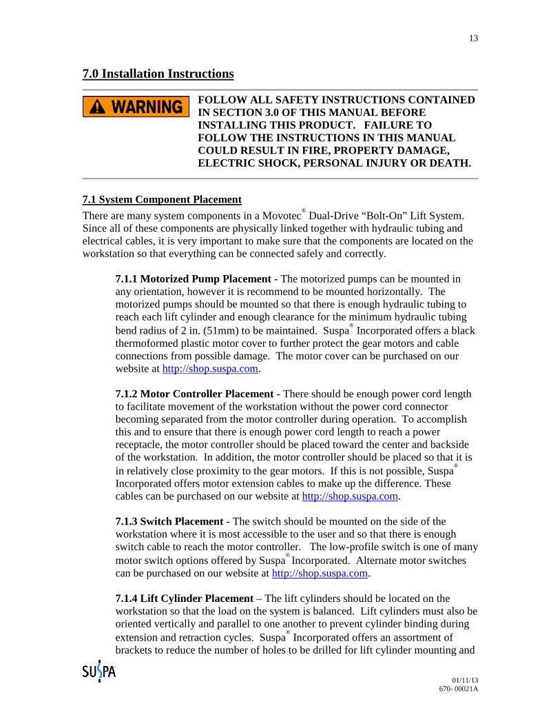
• If possible, orient workstation as shown for ease of component placement and installation.
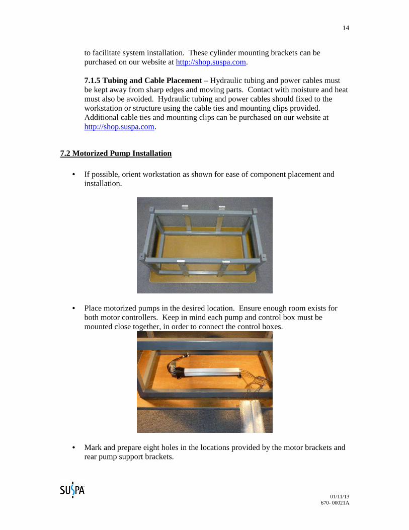
• Place motorized pumps in the desired location. Ensure enough room exists for both motor controllers. Keep in mind each pump and control box must be mounted close together, in order to connect the control boxes.
• Mark and prepare eight holes in the locations provided by the motor brackets and rear pump support brackets.
01/11/13 670- 00021A
15
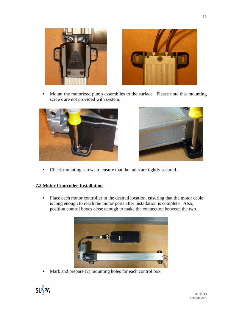
• Mount the motorized pump assemblies to the surface. Please note that mounting screws are not provided with system.
• Check mounting screws to ensure that the units are tightly secured.
7.3 Motor Controller Installation
• Place each motor controller in the desired location, ensuring that the motor cable is long enough to reach the motor ports after installation is complete. Also, position control boxes close enough to make the connection between the two.
• Mark and prepare (2) mounting holes for each control box
01/11/13 670- 00021A
16
• Install controller using mounting screws, and check to ensure that the unit is secured.
7.4 Low Profile Switch Installation
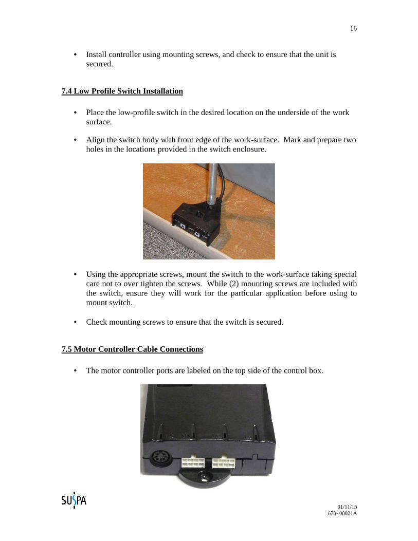
• Place the low-profile switch in the desired location on the underside of the work surface.
• Align the switch body with front edge of the work-surface. Mark and prepare two holes in the locations provided in the switch enclosure.
• Using the appropriate screws, mount the switch to the work-surface taking special care not to over tighten the screws. While (2) mounting screws are included with the switch, ensure they will work for the particular application before using to mount switch.
• Check mounting screws to ensure that the switch is secured.
7.5 Motor Controller Cable Connections
• The motor controller ports are labeled on the top side of the control box.
01/11/13 670- 00021A
17
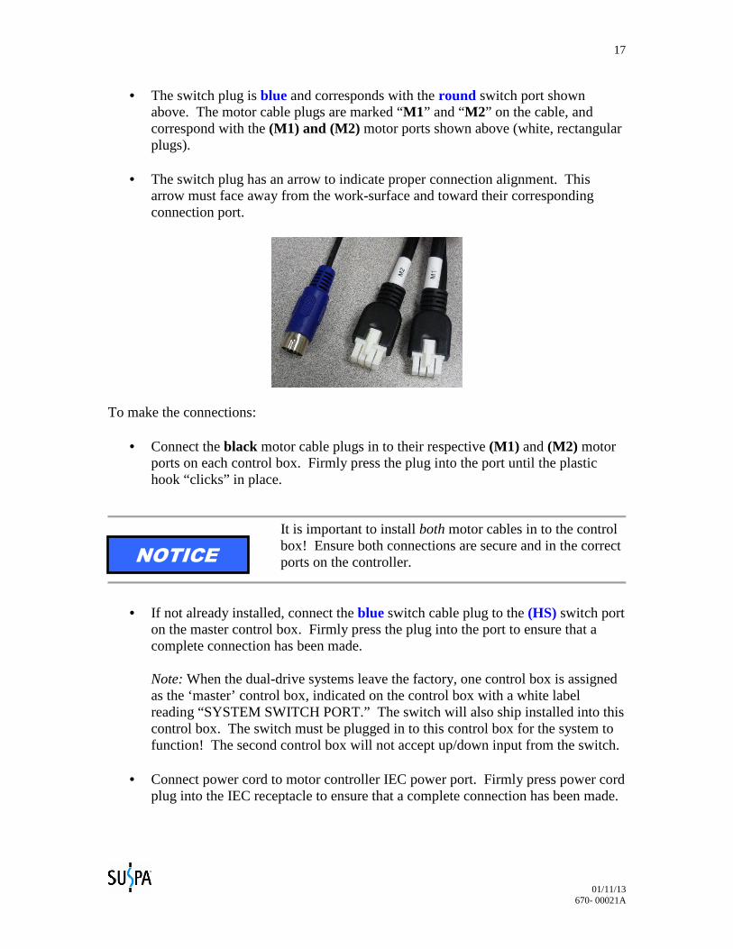
• The switch plug is blue and corresponds with the round switch port shown above. The motor cable plugs are marked “M1” and “M2” on the cable, and correspond with the (M1) and (M2) motor ports shown above (white, rectangular plugs).
• The switch plug has an arrow to indicate proper connection alignment. This arrow must face away from the work-surface and toward their corresponding connection port.
To make the connections:
• Connect the black motor cable plugs in to their respective (M1) and (M2) motor ports on each control box. Firmly press the plug into the port until the plastic hook “clicks” in place.
It is important to install both motor cables in to the control box! Ensure both connections are secure and in the correct ports on the controller.
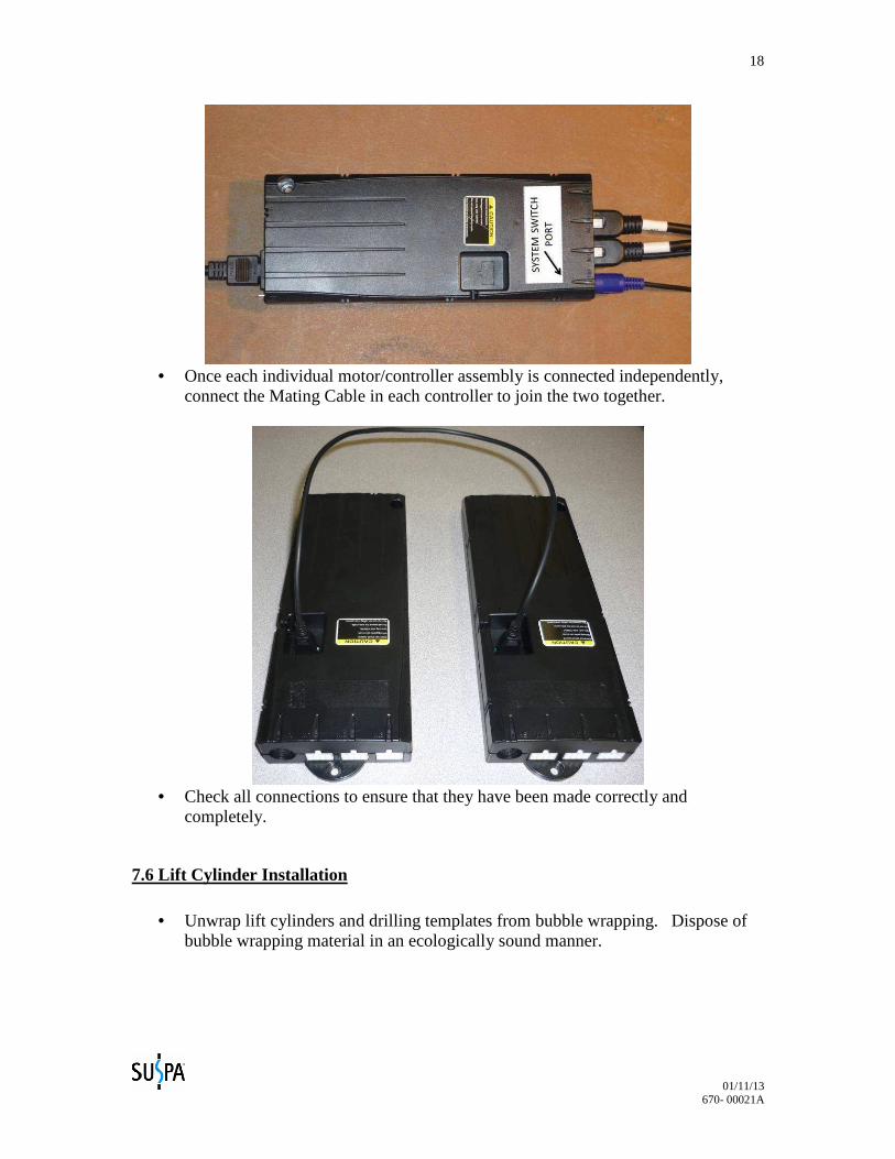
• If not already installed, connect the blue switch cable plug to the (HS) switch port
on the master control box. Firmly press the plug into the port to ensure that a complete connection has been made. Note: When the dual-drive systems leave the factory, one control box is assigned as the ‘master’ control box, indicated on the control box with a white label reading “SYSTEM SWITCH PORT.” The switch will also ship installed into this control box. The switch must be plugged in to this control box for the system to function! The second control box will not accept up/down input from the switch.
• Connect power cord to motor controller IEC power port. Firmly press power cord
plug into the IEC receptacle to ensure that a complete connection has been made.
NOTICE
01/11/13 670- 00021A
18
• Once each individual motor/controller assembly is connected independently,
connect the Mating Cable in each controller to join the two together.
• Check all connections to ensure that they have been made correctly and
completely.
7.6 Lift Cylinder Installation
• Unwrap lift cylinders and drilling templates from bubble wrapping. Dispose of bubble wrapping material in an ecologically sound manner.
01/11/13 670- 00021A
19
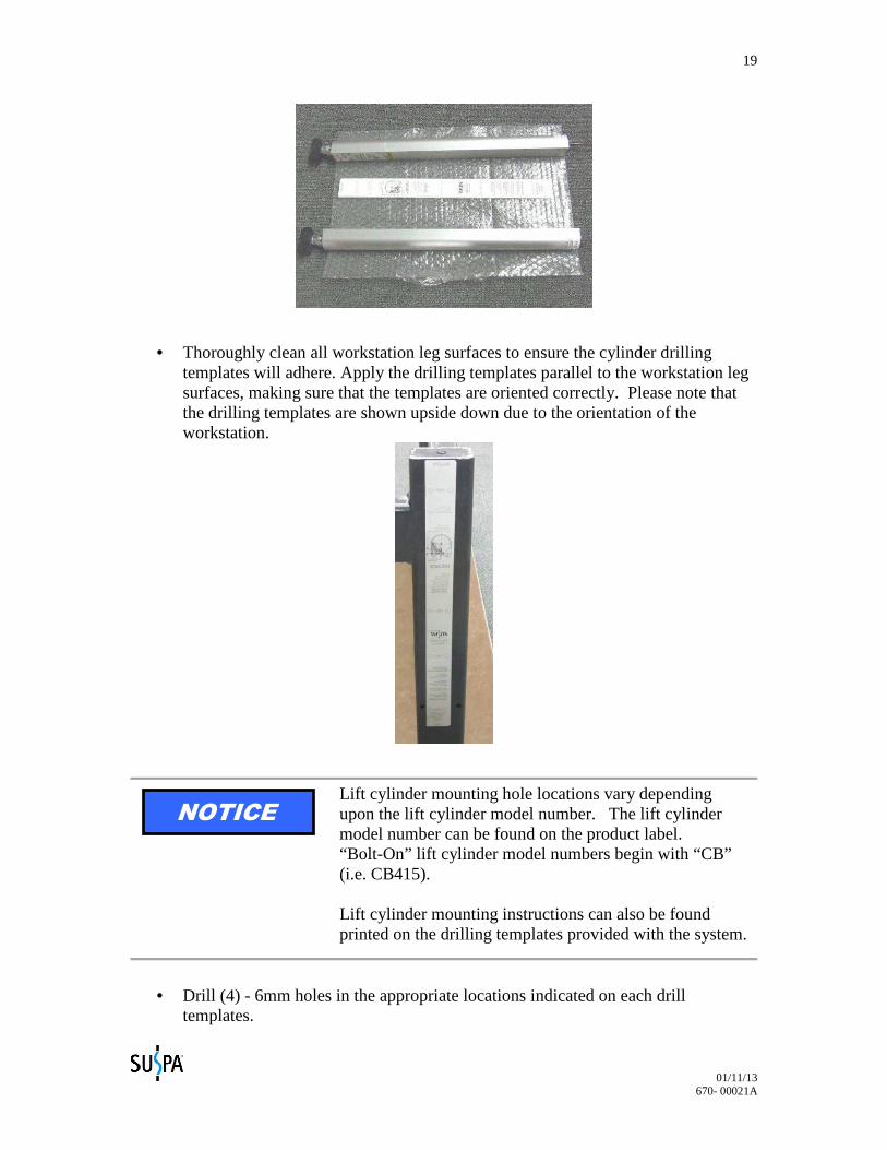
• Thoroughly clean all workstation leg surfaces to ensure the cylinder drilling templates will adhere. Apply the drilling templates parallel to the workstation leg surfaces, making sure that the templates are oriented correctly. Please note that the drilling templates are shown upside down due to the orientation of the workstation.
Lift cylinder mounting hole locations vary depending upon the lift cylinder model number. The lift cylinder model number can be found on the product label. “Bolt-On” lift cylinder model numbers begin with “CB” (i.e. CB415). Lift cylinder mounting instructions can also be found printed on the drilling templates provided with the system.
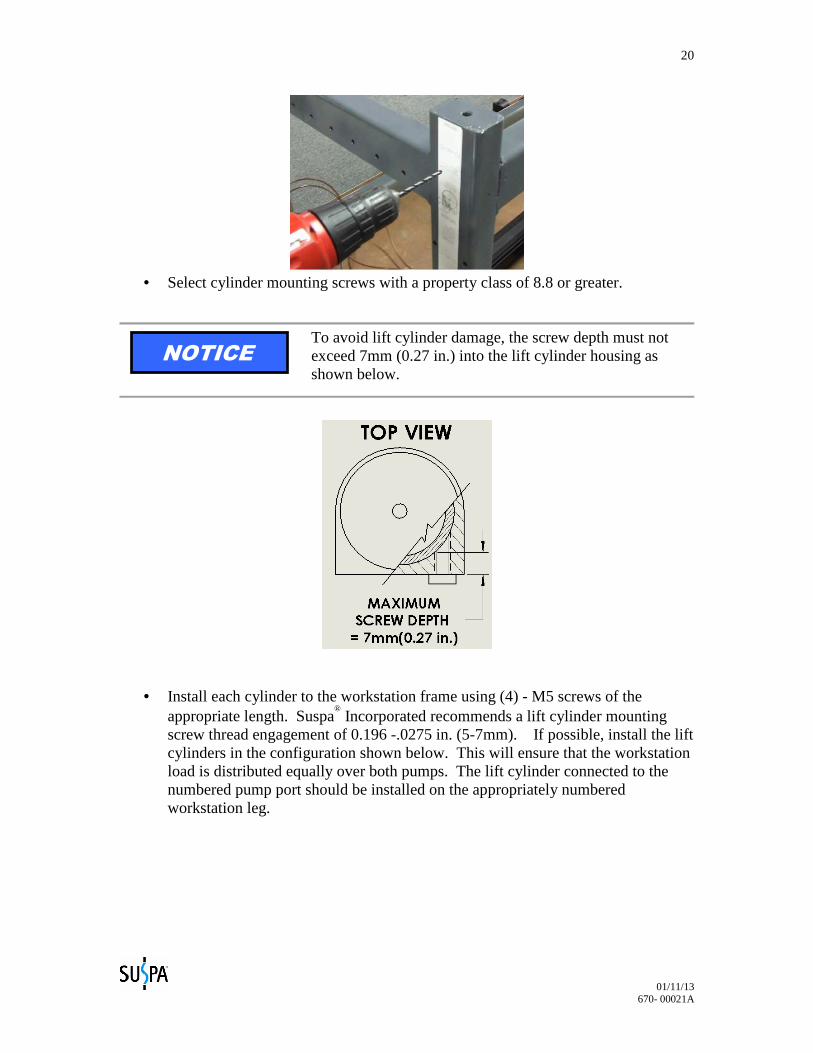
• Drill (4) - 6mm holes in the appropriate locations indicated on each drill templates.
NOTICE
01/11/13 670- 00021A
20
• Select cylinder mounting screws with a property class of 8.8 or greater.
To avoid lift cylinder damage, the screw depth must not exceed 7mm (0.27 in.) into the lift cylinder housing as shown below.
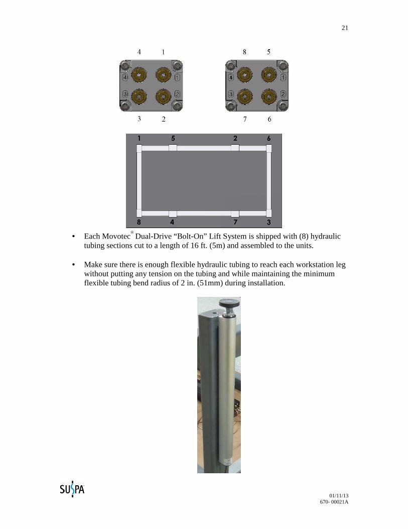
• Install each cylinder to the workstation frame using (4) - M5 screws of the appropriate length. Suspa
® Incorporated recommends a lift cylinder mounting
screw thread engagement of 0.196 -.0275 in. (5-7mm). If possible, install the lift cylinders in the configuration shown below. This will ensure that the workstation load is distributed equally over both pumps. The lift cylinder connected to the numbered pump port should be installed on the appropriately numbered workstation leg.
NOTICE
01/11/13 670- 00021A
21
• Each Movotec
® Dual-Drive “Bolt-On” Lift System is shipped with (8) hydraulic tubing sections cut to a length of 16 ft. (5m) and assembled to the units.
• Make sure there is enough flexible hydraulic tubing to reach each workstation leg
without putting any tension on the tubing and while maintaining the minimum flexible tubing bend radius of 2 in. (51mm) during installation.
01/11/13 670- 00021A
22
• Check the lift cylinder mounting screws to ensure that they are tightly secured to
the workstation. Take special care not to over tighten lift cylinder mounting screws. Suspa
® Incorporated recommends a lift cylinder mounting screw
tightening torque of 35-40 lb-in (4.0-4.5 N-m).
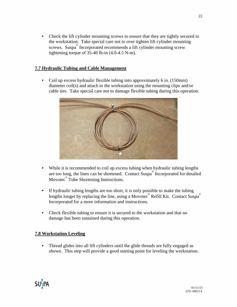
7.7 Hydraulic Tubing and Cable Management • Coil up excess hydraulic flexible tubing into approximately 6 in. (150mm)
diameter coil(s) and attach to the workstation using the mounting clips and/or cable ties. Take special care not to damage flexible tubing during this operation.
• While it is recommended to coil up excess tubing when hydraulic tubing lengths are too long, the lines can be shortened. Contact Suspa
® Incorporated for detailed
Movotec® Tube Shortening Instructions.
• If hydraulic tubing lengths are too short, it is only possible to make the tubing
lengths longer by replacing the line, using a Movotec® Refill Kit. Contact Suspa
®
Incorporated for a more information and instructions.
• Check flexible tubing to ensure it is secured to the workstation and that no damage has been sustained during this operation.
7.8 Workstation Leveling
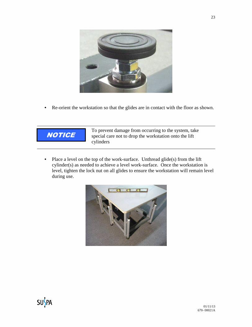
• Thread glides into all lift cylinders until the glide threads are fully engaged as shown. This step will provide a good starting point for leveling the workstation.
01/11/13 670- 00021A
23
• Re-orient the workstation so that the glides are in contact with the floor as shown.
To prevent damage from occurring to the system, take special care not to drop the workstation onto the lift cylinders
• Place a level on the top of the work-surface. Unthread glide(s) from the lift cylinder(s) as needed to achieve a level work-surface. Once the workstation is level, tighten the lock nut on all glides to ensure the workstation will remain level during use.
NOTICE
01/11/13 670- 00021A
24
8.0 Operation Instructions
FOLLOW ALL SAFETY INSTRUCTIONS CONTAINED IN SECTION 3.0 OF THIS MANUAL BEFORE OPERATING THIS PRODUCT. FAILURE TO FOLLOW THE INSTRUCTIONS IN THIS MANUAL COULD RESULT IN FIRE, PROPERTY DAMAGE,
ELECTRIC SHOCK, PERSONAL INJURY OR DEATH.
The Movotec® Dual-Drive “Bolt-On” Lift System is a motor driven single-acting fluid
displacement lift system designed to make workstations ergonomically height adjustable. These lift systems can lift relatively large loads up and down for many years as long as they are installed and used correctly. The Movotec
® Dual-Drive “Bolt-On” Lift System is not intended for continuous cycling or for applications requiring precision height adjustment.
The Movotec
® lift system is single-acting and will require a
minimum load of 35 lb (15.9 kg) per cylinder for even lift system retraction.
8.1 Before Connecting to Power
• Check all electrical and hydraulic connections. • Check for damage to power cords or flexible hydraulic tubing that may have
occurred while unpacking or installing the system. • Check all system components to ensure that they are tightly secured to the work
station. • Make sure that a minimum load of 35 lb (15.9 kg) per lift cylinder is present for
even lift system retraction. • Make sure the maximum system load rating is not being exceeded. The
maximum system load is defined as the total load of the workstation, the lift system, and any additional load on the work-surface.
8.2 Connecting to Power
Prior to connecting system to power, make sure that the
power supply voltage matches motor controller nameplate and all cables are fully connected to the correct electrical ports.
NOTICE
NOTICE
01/11/13 670- 00021A
25
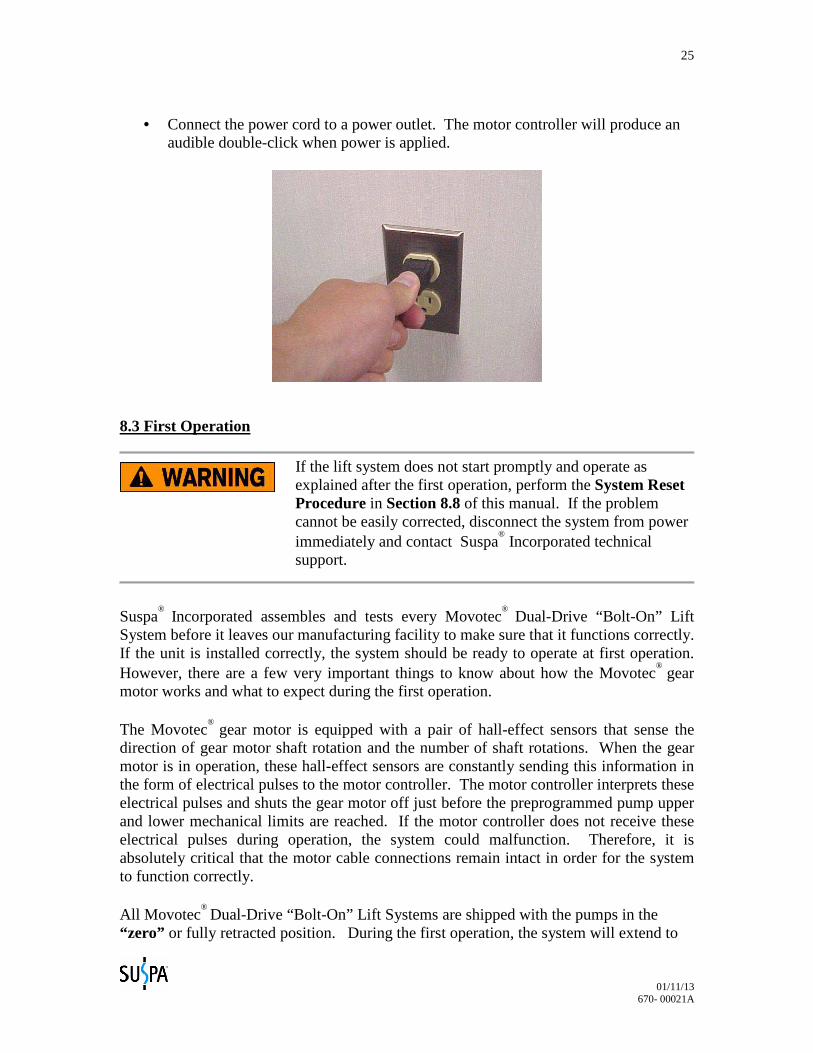
• Connect the power cord to a power outlet. The motor controller will produce an
audible double-click when power is applied.
8.3 First Operation
If the lift system does not start promptly and operate as explained after the first operation, perform the System Reset
Procedure in Section 8.8 of this manual. If the problem cannot be easily corrected, disconnect the system from power immediately and contact Suspa
® Incorporated technical
support.
Suspa
® Incorporated assembles and tests every Movotec® Dual-Drive “Bolt-On” Lift
System before it leaves our manufacturing facility to make sure that it functions correctly. If the unit is installed correctly, the system should be ready to operate at first operation. However, there are a few very important things to know about how the Movotec
® gear motor works and what to expect during the first operation. The Movotec
® gear motor is equipped with a pair of hall-effect sensors that sense the direction of gear motor shaft rotation and the number of shaft rotations. When the gear motor is in operation, these hall-effect sensors are constantly sending this information in the form of electrical pulses to the motor controller. The motor controller interprets these electrical pulses and shuts the gear motor off just before the preprogrammed pump upper and lower mechanical limits are reached. If the motor controller does not receive these electrical pulses during operation, the system could malfunction. Therefore, it is absolutely critical that the motor cable connections remain intact in order for the system to function correctly. All Movotec
® Dual-Drive “Bolt-On” Lift Systems are shipped with the pumps in the “zero” or fully retracted position. During the first operation, the system will extend to
01/11/13 670- 00021A
26
the pump “home” position which leaves a 0.12 in. (3mm) space just above the lower mechanical limit and just below the upper mechanical limit of the pumps. This space has been programmed into the motor controller to prevent the pumps from bottoming out in the extended and retracted positions during operation.
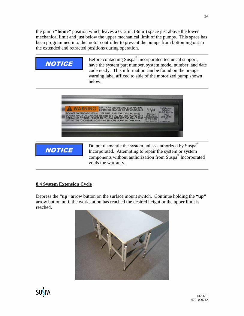
Before contacting Suspa
® Incorporated technical support, please have the system part number, system model number, and date
code ready. This information can be found on the orange warning label affixed to side of the motorized pump shown below.
Do not dismantle the system unless authorized by Suspa®
Incorporated. Attempting to repair the system or system components without authorization from Suspa
® Incorporated
voids the warranty.
8.4 System Extension Cycle Depress the “up” arrow button on the surface mount switch. Continue holding the “up” arrow button until the workstation has reached the desired height or the upper limit is reached.
NOTICE
NOTICE
01/11/13 670- 00021A
27
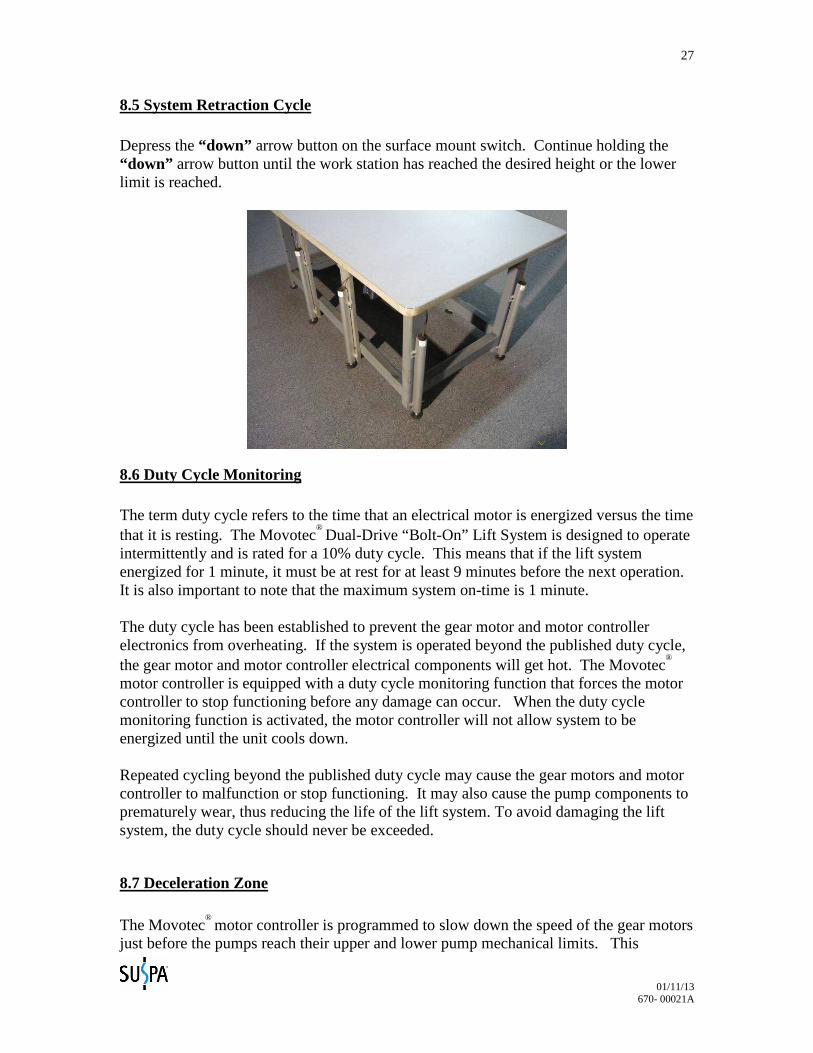
8.5 System Retraction Cycle Depress the “down” arrow button on the surface mount switch. Continue holding the “down” arrow button until the work station has reached the desired height or the lower limit is reached.
8.6 Duty Cycle Monitoring The term duty cycle refers to the time that an electrical motor is energized versus the time that it is resting. The Movotec
® Dual-Drive “Bolt-On” Lift System is designed to operate intermittently and is rated for a 10% duty cycle. This means that if the lift system energized for 1 minute, it must be at rest for at least 9 minutes before the next operation. It is also important to note that the maximum system on-time is 1 minute. The duty cycle has been established to prevent the gear motor and motor controller electronics from overheating. If the system is operated beyond the published duty cycle, the gear motor and motor controller electrical components will get hot. The Movotec
®
motor controller is equipped with a duty cycle monitoring function that forces the motor controller to stop functioning before any damage can occur. When the duty cycle monitoring function is activated, the motor controller will not allow system to be energized until the unit cools down.
Repeated cycling beyond the published duty cycle may cause the gear motors and motor controller to malfunction or stop functioning. It may also cause the pump components to prematurely wear, thus reducing the life of the lift system. To avoid damaging the lift system, the duty cycle should never be exceeded.
8.7 Deceleration Zone The Movotec
® motor controller is programmed to slow down the speed of the gear motors just before the pumps reach their upper and lower pump mechanical limits. This
01/11/13 670- 00021A
28
deceleration zone provides a good indicator for the user that the lift system is about to reach its fully extended or retracted height.
8.8 System Reset Procedure The following procedure should be used to reset a Movotec® motor controller and pump(s) to their respective “home” positions. The procedure should be performed only if the following conditions exist:
1.) A new or replacement controller is introduced to an existing motor driven system. The Movotec® gear motor and motor controller leaves our manufacturing facility programmed as a matched set. If a different motor controller is used other than the one that was sent with the original unit, it must be matched and reset with the original motorized pump using the system reset procedure below.
2.) The motor cable is disconnected from the gear motor.
If this happens, reconnect the motor cable to the gear motor. Perform the system reset procedure below to ensure that the motorized pump will function within its preprogrammed limits.
3.) The system is behaving unusually.
Although it is not very common, a power outage can cause a motor controller to lose its programmed position. If this happens, the motors may move in one revolution increments in one or both directions. To remedy this problem, perform the system reset procedure below.
System Reset Procedure
• Press the surface mount switch “down” arrow button. Continue holding the switch “down” arrow button until the workstation stops moving or reaches its fully retracted position.
• Remove finger from switch. • Press and hold the switch “down” arrow button again. It will take approximately
5 seconds before the system will begin to retract until the “zero” position is reached.
• The system is now reset and ready for normal operation.
01/11/13 670- 00021A
29
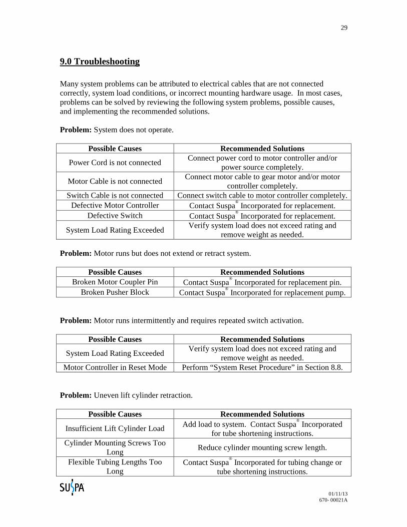
9.0 Troubleshooting Many system problems can be attributed to electrical cables that are not connected correctly, system load conditions, or incorrect mounting hardware usage. In most cases, problems can be solved by reviewing the following system problems, possible causes, and implementing the recommended solutions. Problem: System does not operate.
Possible Causes Recommended Solutions
Power Cord is not connected Connect power cord to motor controller and/or
power source completely.
Motor Cable is not connected Connect motor cable to gear motor and/or motor
controller completely. Switch Cable is not connected Connect switch cable to motor controller completely.
Defective Motor Controller Contact Suspa® Incorporated for replacement.
Defective Switch Contact Suspa® Incorporated for replacement.
System Load Rating Exceeded Verify system load does not exceed rating and
remove weight as needed. Problem: Motor runs but does not extend or retract system.
Possible Causes Recommended Solutions Broken Motor Coupler Pin Contact Suspa
® Incorporated for replacement pin.
Broken Pusher Block Contact Suspa® Incorporated for replacement pump.
Problem: Motor runs intermittently and requires repeated switch activation.
Possible Causes Recommended Solutions
System Load Rating Exceeded Verify system load does not exceed rating and
remove weight as needed. Motor Controller in Reset Mode Perform “System Reset Procedure” in Section 8.8.
Problem: Uneven lift cylinder retraction.
Possible Causes Recommended Solutions
Insufficient Lift Cylinder Load Add load to system. Contact Suspa® Incorporated
for tube shortening instructions. Cylinder Mounting Screws Too
Long Reduce cylinder mounting screw length.
Flexible Tubing Lengths Too Long
Contact Suspa® Incorporated for tubing change or
tube shortening instructions.
01/11/13 670- 00021A
30
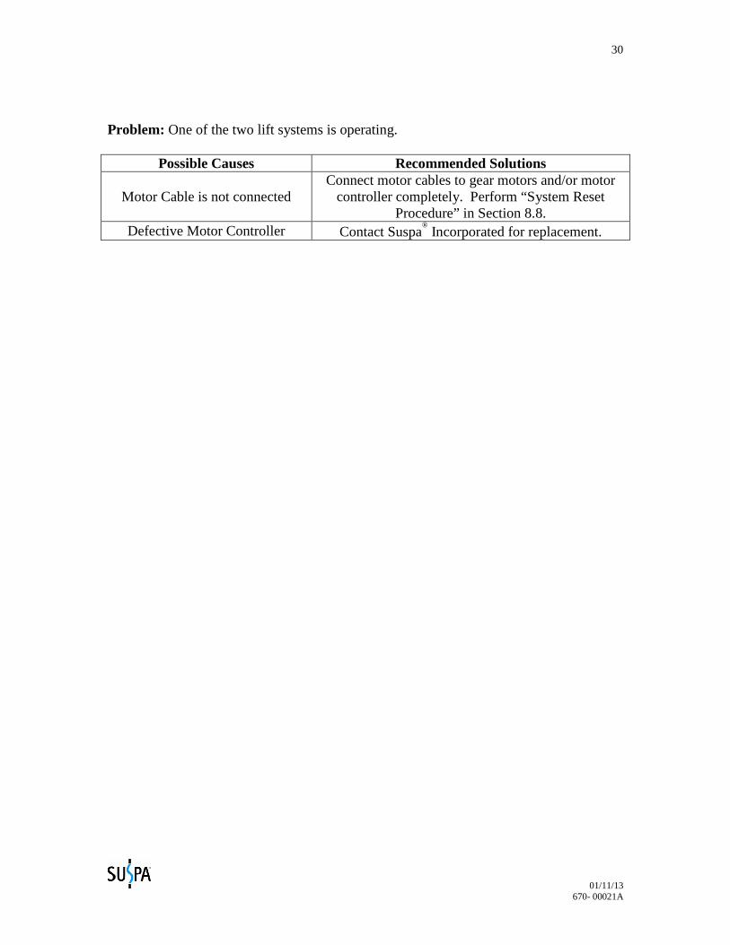
Problem: One of the two lift systems is operating.
Possible Causes Recommended Solutions
Motor Cable is not connected Connect motor cables to gear motors and/or motor
controller completely. Perform “System Reset Procedure” in Section 8.8.
Defective Motor Controller Contact Suspa® Incorporated for replacement.
01/11/13 670- 00021A
31
10.0 Inspection and Maintenance
FOLLOW ALL SAFETY INSTRUCTIONS CONTAINED IN SECTION 3.0 OF THIS MANUAL BEFORE PERFORMING INSPECTION AND MAINTENANCE
PROCEDURES ON THIS PRODUCT. FAILURE TO FOLLOW THE INSTRUCTIONS IN THIS MANUAL COULD RESULT IN FIRE, PROPERTY DAMAGE, ELECTRIC SHOCK, PERSONAL INJURY OR DEATH.
The Movotec
® Dual-Drive “Bolt-On” Lift System should be inspected regularly to detect
any condition which has or may lead to excessive component wear or premature failure. Special attention should be given to the following possible causes of motor or system failure.
10.1 Changing Load Conditions Overload conditions should be promptly corrected to prevent premature wear of mechanical components. This will also prevent overheating and premature failure of electrical components.
10.2 Motor and Load Alignment Pump and motor shafts can become misaligned if a lift system is installed incorrectly or if a motorized pump sustains an impact during transit or use. Misaligned motor and pump shafts can cause noise and uneven wear to the driving components which can lead to premature failure of the system. If the system drive shafts become misaligned, correct the alignment as needed.
10.3 Contamination Although surgical cleanliness is not required, ordinary cleaning practices will pay off in increased service life of the lift system. Dust and dirt can restrict ventilation for electrical components and cause wear in moving components such as shafts and bearings. An attempt should be made to keep the system components reasonably clean throughout their useable service life.
10.4 Power Cord and Hydraulic Tubing Damage Check the power cord insulation and hydraulic tubing for visible signs of aging and wear. Replacement of damaged wiring and tubing will prevent future breakdowns and possible injury to personnel.
01/11/13 670- 00021A
32
11.0 Warranty Suspa
® Incorporated warrants that if the Movotec
® Dual-Drive “Bolt-On” Lift System has
been properly installed and not subject to abuse or misuse and proves to be defective (as defined below) within the Applicable Warranty Period after the date of manufacture of the item by Suspa
® Incorporated or, if applicable, by Suspa
® Incorporated’s supplier and if
the Buyer returns the item to Seller within that period, F.O.B. Suspa®
Incorporated’s plant in Grand Rapids, Michigan, then Suspa
® Incorporated shall, at Suspa
® Incorporated’s
option, either repair of replace the defective item, at Suspa®
Incorporated’s expense. If Suspa
® Incorporated fails to repair or replace a defective item within a reasonable time,
then Suspa®
Incorporated shall be liable to the Buyer for the lesser of (1) the reasonable costs of repair or replacement by a third party or (2) that part of the purchase price of the defective goods that the Buyer shall have paid, but the Buyer shall not obtain repair or replacement by a third party without giving Suspa
® Incorporated at least fifteen (15) days
prior written notice, during which time Suspa®
Incorporated may repair or replace the defective item. An item shall be considered “defective” if Suspa
® Incorporated finds that
it is defective in materials or workmanship and if the defect materially impairs the value of the goods to the Buyer, except that if the Buyer shall have approved drawings of, or specifications for, or production samples of the goods, then the goods shall not be defective to the extent that they conform to the drawings, specifications, or samples. This paragraph sets forth the Buyer’s sole and exclusive remedies for any defect in the goods. The Applicable Warranty Period for the Movotec
® Dual-Drive “Bolt-On” Lift System is
two years. EXCEPT AS STATED IN THE PREVIOUS PARAGRAPH, SUSPA
®
INCORPORATED DOES NOT MAKE ANY WARRANTY AS TO THE G OODS AND, IN PARTICULAR, DOES NOT MAKE ANY WARRANTY OF MERCHANTABILITY OR FITNESS FOR ANY PARTICULAR PURPO SE, AND THE BUYER IS SOLELY RESPONSIBLE FOR DETERMINING THE PROPER APPLICATION AND USE OF THE GOODS. Suspa
® Incorporated shall not have any
tort liability to the Buyer with respect to any of the goods and shall not be liable for consequential or incidental damages that arise from any product defect, delay, nondelivery, or other breach. The Buyer shall not have any right of rejection or of revocation of acceptance of Movotec
® Dual-Drive “Bolt-On” Lift System products.
If you have any questions regarding the warranty or believe that you have received a defective component, please contact Suspa
® Incorporated.
01/11/13 670- 00021A
33
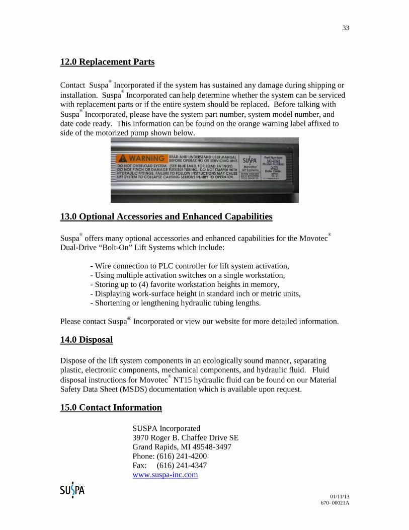
12.0 Replacement Parts Contact Suspa
® Incorporated if the system has sustained any damage during shipping or
installation. Suspa® Incorporated can help determine whether the system can be serviced
with replacement parts or if the entire system should be replaced. Before talking with Suspa
® Incorporated, please have the system part number, system model number, and
date code ready. This information can be found on the orange warning label affixed to side of the motorized pump shown below.
13.0 Optional Accessories and Enhanced Capabilities Suspa
® offers many optional accessories and enhanced capabilities for the Movotec
®
Dual-Drive “Bolt-On” Lift Systems which include: - Wire connection to PLC controller for lift system activation, - Using multiple activation switches on a single workstation, - Storing up to (4) favorite workstation heights in memory, - Displaying work-surface height in standard inch or metric units, - Shortening or lengthening hydraulic tubing lengths. Please contact Suspa® Incorporated or view our website for more detailed information.
14.0 Disposal Dispose of the lift system components in an ecologically sound manner, separating plastic, electronic components, mechanical components, and hydraulic fluid. Fluid disposal instructions for Movotec
® NT15 hydraulic fluid can be found on our Material
Safety Data Sheet (MSDS) documentation which is available upon request.
15.0 Contact Information SUSPA Incorporated
3970 Roger B. Chaffee Drive SE Grand Rapids, MI 49548-3497 Phone: (616) 241-4200 Fax: (616) 241-4347 www.suspa-inc.com