Embed Size (px)
Citation preview
1
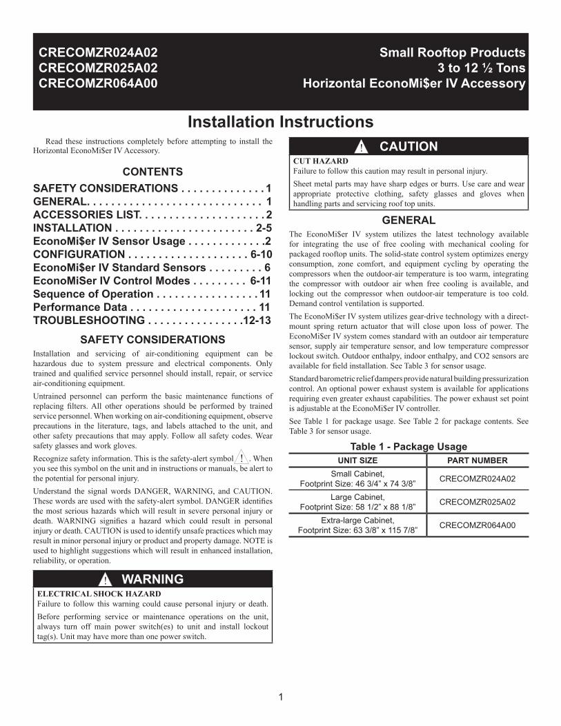
Installation Instructions Read these instructions completely before attempting to install the Horizontal EconoMi$er IV Accessory.
CONTENTSSAFETY CONSIDERATIONS . . . . . . . . . . . . . . 1GENERAL. . . . . . . . . . . . . . . . . . . . . . . . . . . . . 1ACCESSORIES LIST. . . . . . . . . . . . . . . . . . . . . 2INSTALLATION . . . . . . . . . . . . . . . . . . . . . . . 2-5EconoMi$er IV Sensor Usage . . . . . . . . . . . . .2CONFIGURATION . . . . . . . . . . . . . . . . . . . . 6-10EconoMi$er IV Standard Sensors . . . . . . . . . 6EconoMiSer IV Control Modes . . . . . . . . . 6-11Sequence of Operation . . . . . . . . . . . . . . . . . 11Performance Data . . . . . . . . . . . . . . . . . . . . . 11TROUBLESHOOTING . . . . . . . . . . . . . . . .12-13
SAFETY CONSIDERATIONSInstallation and servicing of air-conditioning equipment can be hazardous due to system pressure and electrical components. Only trained and qualified service personnel should install, repair, or service air-conditioning equipment.Untrained personnel can perform the basic maintenance functions of replacing filters. All other operations should be performed by trained service personnel. When working on air-conditioning equipment, observe precautions in the literature, tags, and labels attached to the unit, and other safety precautions that may apply. Follow all safety codes. Wear safety glasses and work gloves.Recognize safety information. This is the safety-alert symbol . When you see this symbol on the unit and in instructions or manuals, be alert to the potential for personal injury.Understand the signal words DANGER, WARNING, and CAUTION. These words are used with the safety-alert symbol. DANGER identifies the most serious hazards which will result in severe personal injury or death. WARNING signifies a hazard which could result in personal injury or death. CAUTION is used to identify unsafe practices which may result in minor personal injury or product and property damage. NOTE is used to highlight suggestions which will result in enhanced installation, reliability, or operation.
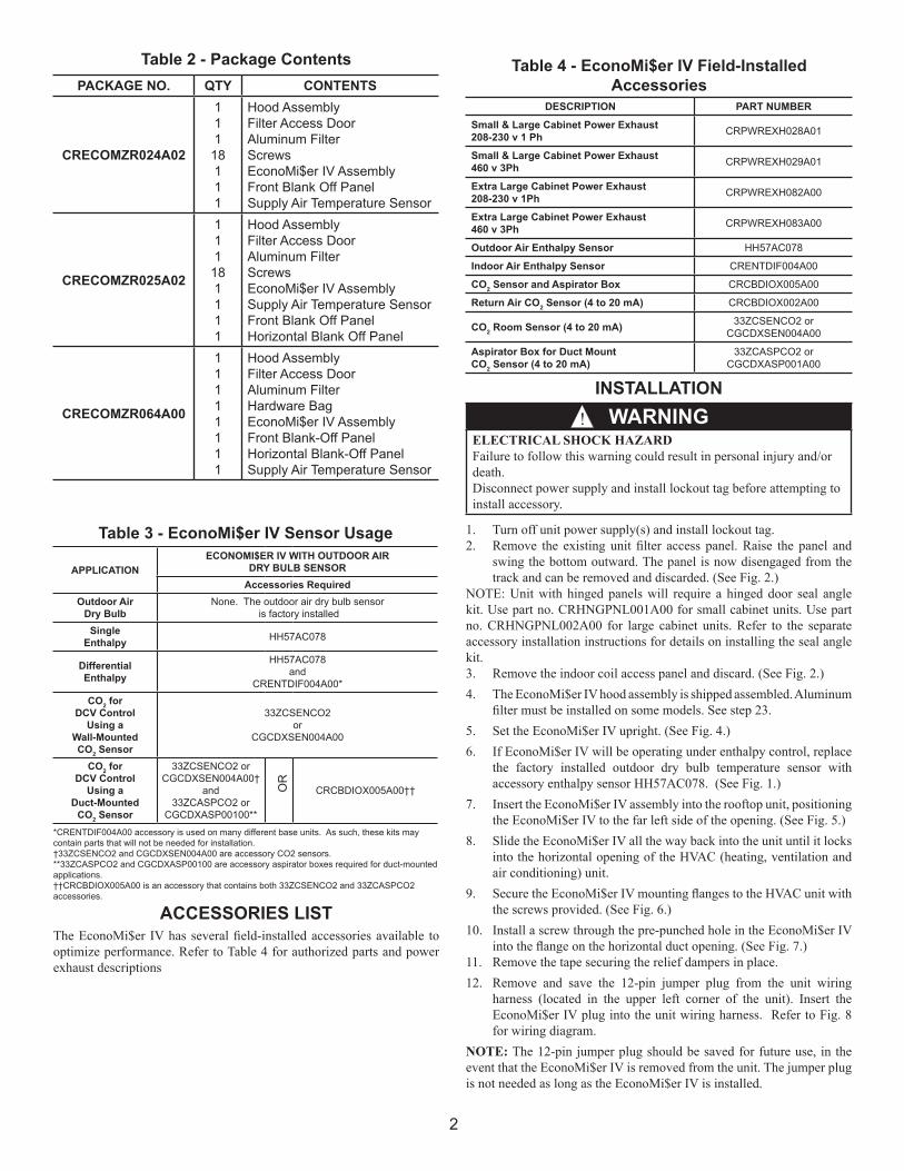
Table 1 - Package UsageUNIT SIZE PART NUMBER
Small Cabinet,Footprint Size: 46 3/4” x 74 3/8” CRECOMZR024A02
Large Cabinet,Footprint Size: 58 1/2” x 88 1/8” CRECOMZR025A02
Extra-large Cabinet,Footprint Size: 63 3/8” x 115 7/8” CRECOMZR064A00
GENERALThe EconoMi$er IV system utilizes the latest technology available for integrating the use of free cooling with mechanical cooling for packaged rooftop units. The solid-state control system optimizes energy consumption, zone comfort, and equipment cycling by operating the compressors when the outdoor-air temperature is too warm, integrating the compressor with outdoor air when free cooling is available, and locking out the compressor when outdoor-air temperature is too cold. Demand control ventilation is supported. The EconoMi$er IV system utilizes gear-drive technology with a direct-mount spring return actuator that will close upon loss of power. The EconoMi$er IV system comes standard with an outdoor air temperature sensor, supply air temperature sensor, and low temperature compressor lockout switch. Outdoor enthalpy, indoor enthalpy, and CO2 sensors are available for field installation. See Table 3 for sensor usage.Standard barometric relief dampers provide natural building pressurization control. An optional power exhaust system is available for applications requiring even greater exhaust capabilities. The power exhaust set point is adjustable at the EconoMi$er IV controller.See Table 1 for package usage. See Table 2 for package contents. See Table 3 for sensor usage.
Small Rooftop Products3 to 12 ½ Tons
Horizontal EconoMi$er IV Accessory
CRECOMZR024A02CRECOMZR025A02CRECOMZR064A00
WARNINGELECTRICAL SHOCK HAZARDFailure to follow this warning could cause personal injury or death. Before performing service or maintenance operations on the unit, always turn off main power switch(es) to unit and install lockout tag(s). Unit may have more than one power switch.
!
!
CAUTIONCUT HAZARDFailure to follow this caution may result in personal injury. Sheet metal parts may have sharp edges or burrs. Use care and wear appropriate protective clothing, safety glasses and gloves when handling parts and servicing roof top units.
!
2
ACCESSORIES LISTThe EconoMi$er IV has several field-installed accessories available to optimize performance. Refer to Table 4 for authorized parts and power exhaust descriptions
INSTALLATION
Table 3 - EconoMi$er IV Sensor Usage
APPLICATIONECONOMI$ER IV WITH OUTDOOR AIR
DRY BULB SENSORAccessories Required
Outdoor AirDry Bulb
None. The outdoor air dry bulb sensor is factory installed
SingleEnthalpy HH57AC078
DifferentialEnthalpy
HH57AC078and
CRENTDIF004A00*
CO2 forDCV Control
Using aWall-MountedCO2 Sensor
33ZCSENCO2or
CGCDXSEN004A00
CO2 for DCV Control
Using a Duct-Mounted
CO2 Sensor
33ZCSENCO2 orCGCDXSEN004A00†
and33ZCASPCO2 or
CGCDXASP00100**
CRCBDIOX005A00††OR
*CRENTDIF004A00 accessory is used on many different base units. As such, these kits may contain parts that will not be needed for installation.†33ZCSENCO2 and CGCDXSEN004A00 are accessory CO2 sensors.**33ZCASPCO2 and CGCDXASP00100 are accessory aspirator boxes required for duct-mounted applications.††CRCBDIOX005A00 is an accessory that contains both 33ZCSENCO2 and 33ZCASPCO2 accessories.
Table 4 - EconoMi$er IV Field-Installed Accessories
DESCRIPTION PART NUMBER
Small & Large Cabinet Power Exhaust 208-230 v 1 Ph CRPWREXH028A01
Small & Large Cabinet Power Exhaust 460 v 3Ph CRPWREXH029A01
Extra Large Cabinet Power Exhaust208-230 v 1Ph CRPWREXH082A00
Extra Large Cabinet Power Exhaust460 v 3Ph CRPWREXH083A00
Outdoor Air Enthalpy Sensor HH57AC078
Indoor Air Enthalpy Sensor CRENTDIF004A00
CO2 Sensor and Aspirator Box CRCBDIOX005A00
Return Air CO2 Sensor (4 to 20 mA) CRCBDIOX002A00
CO2 Room Sensor (4 to 20 mA) 33ZCSENCO2 orCGCDXSEN004A00
Aspirator Box for Duct MountCO2 Sensor (4 to 20 mA)
33ZCASPCO2 orCGCDXASP001A00
WARNINGELECTRICAL SHOCK HAZARDFailure to follow this warning could result in personal injury and/or death.Disconnect power supply and install lockout tag before attempting to install accessory.
!
Table 2 - Package ContentsPACKAGE NO. QTY CONTENTS
CRECOMZR024A02
111
18111
Hood AssemblyFilter Access DoorAluminum FilterScrewsEconoMi$er IV AssemblyFront Blank Off PanelSupply Air Temperature Sensor
CRECOMZR025A02
111
181111
Hood AssemblyFilter Access DoorAluminum FilterScrewsEconoMi$er IV AssemblySupply Air Temperature SensorFront Blank Off PanelHorizontal Blank Off Panel
CRECOMZR064A00
11111111
Hood AssemblyFilter Access DoorAluminum FilterHardware BagEconoMi$er IV AssemblyFront Blank-Off PanelHorizontal Blank-Off PanelSupply Air Temperature Sensor
1. Turn off unit power supply(s) and install lockout tag.2. Remove the existing unit filter access panel. Raise the panel and
swing the bottom outward. The panel is now disengaged from the track and can be removed and discarded. (See Fig. 2.)
NOTE: Unit with hinged panels will require a hinged door seal angle kit. Use part no. CRHNGPNL001A00 for small cabinet units. Use part no. CRHNGPNL002A00 for large cabinet units. Refer to the separate accessory installation instructions for details on installing the seal angle kit.3. Remove the indoor coil access panel and discard. (See Fig. 2.)4. The EconoMi$er IV hood assembly is shipped assembled. Aluminum
filter must be installed on some models. See step 23.5. Set the EconoMi$er IV upright. (See Fig. 4.)6. If EconoMi$er IV will be operating under enthalpy control, replace
the factory installed outdoor dry bulb temperature sensor with accessory enthalpy sensor HH57AC078. (See Fig. 1.)
7. Insert the EconoMi$er IV assembly into the rooftop unit, positioning the EconoMi$er IV to the far left side of the opening. (See Fig. 5.)
8. Slide the EconoMi$er IV all the way back into the unit until it locks into the horizontal opening of the HVAC (heating, ventilation and air conditioning) unit.
9. Secure the EconoMi$er IV mounting flanges to the HVAC unit with the screws provided. (See Fig. 6.)
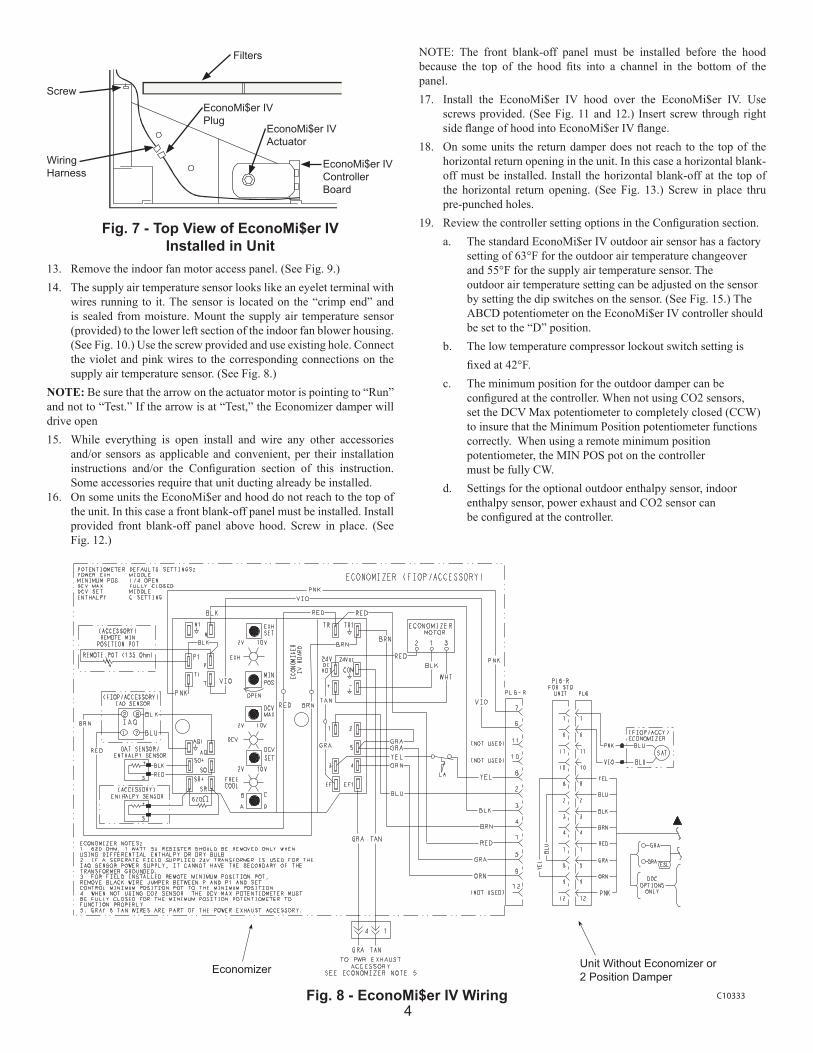
10. Install a screw through the pre-punched hole in the EconoMi$er IV into the flange on the horizontal duct opening. (See Fig. 7.)
11. Remove the tape securing the relief dampers in place.12. Remove and save the 12-pin jumper plug from the unit wiring
harness (located in the upper left corner of the unit). Insert the EconoMi$er IV plug into the unit wiring harness. Refer to Fig. 8 for wiring diagram.
NOTE: The 12-pin jumper plug should be saved for future use, in the event that the EconoMi$er IV is removed from the unit. The jumper plug is not needed as long as the EconoMi$er IV is installed.
3
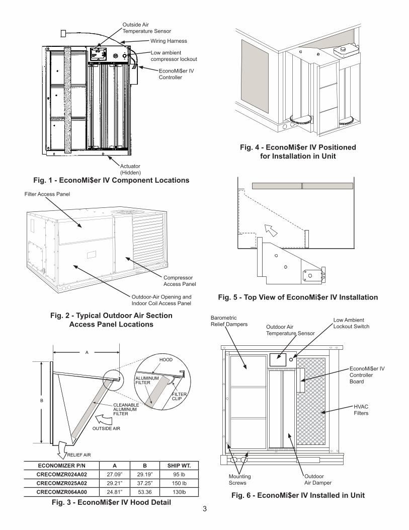
Fig. 1 - EconoMi$er IV Component Locations
Fig. 3 - EconoMi$er IV Hood Detail
Fig. 2 - Typical Outdoor Air Section Access Panel Locations
Fig. 5 - Top View of EconoMi$er IV Installation
Fig. 6 - EconoMi$er IV Installed in Unit
Fig. 4 - EconoMi$er IV Positionedfor Installation in Unit
CompressorAccess Panel
Outside AirTemperature Sensor
Actuator(Hidden)
Wiring Harness
EconoMi$er IVController
Low ambient compressor lockout
Barometric Relief Dampers Outdoor Air
Temperature Sensor
Low AmbientLockout Switch
EconoMi$er IVControllerBoard
HVAC Filters
OutdoorAir Damper
Mounting Screws
Outdoor-Air Opening and Indoor Coil Access Panel
Filter Access Panel
ECONOMIZER P/N A B SHIP WT.CRECOMZR024A02 27.09” 29.19” 95 lbCRECOMZR025A02 29.21” 37.25” 150 lbCRECOMZR064A00 24.81” 53.36 130lb
B
A
HOOD
ALUMINUMFILTER
FILTERCLIP
CLEANABLEALUMINUMFILTER
OUTSIDE AIR
RELIEF AIR
4
Economizer Unit Without Economizer or2 Position Damper
C10333Fig. 8 - EconoMi$er IV Wiring
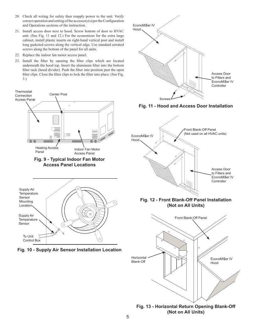
NOTE: The front blank-off panel must be installed before the hood because the top of the hood fits into a channel in the bottom of the panel.17. Install the EconoMi$er IV hood over the EconoMi$er IV. Use
screws provided. (See Fig. 11 and 12.) Insert screw through right side flange of hood into EconoMi$er IV flange.
18. On some units the return damper does not reach to the top of the horizontal return opening in the unit. In this case a horizontal blank-off must be installed. Install the horizontal blank-off at the top of the horizontal return opening. (See Fig. 13.) Screw in place thru pre-punched holes.
19. Review the controller setting options in the Configuration section. a. The standard EconoMi$er IV outdoor air sensor has a factory
setting of 63°F for the outdoor air temperature changeover and 55°F for the supply air temperature sensor. The
outdoor air temperature setting can be adjusted on the sensor by setting the dip switches on the sensor. (See Fig. 15.) The ABCD potentiometer on the EconoMi$er IV controller should be set to the “D” position.
b. The low temperature compressor lockout switch setting is fixed at 42°F.
c. The minimum position for the outdoor damper can be configured at the controller. When not using CO2 sensors,
set the DCV Max potentiometer to completely closed (CCW) to insure that the Minimum Position potentiometer functions correctly. When using a remote minimum position potentiometer, the MIN POS pot on the controller must be fully CW.
d. Settings for the optional outdoor enthalpy sensor, indoor enthalpy sensor, power exhaust and CO2 sensor can be configured at the controller.
Fig. 7 - Top View of EconoMi$er IV Installed in Unit
Filters
EconoMi$er IVPlug
EconoMi$er IVActuator
EconoMi$er IVControllerBoard
Screw
WiringHarness
13. Remove the indoor fan motor access panel. (See Fig. 9.)14. The supply air temperature sensor looks like an eyelet terminal with
wires running to it. The sensor is located on the “crimp end” and is sealed from moisture. Mount the supply air temperature sensor (provided) to the lower left section of the indoor fan blower housing. (See Fig. 10.) Use the screw provided and use existing hole. Connect the violet and pink wires to the corresponding connections on the supply air temperature sensor. (See Fig. 8.)
NOTE: Be sure that the arrow on the actuator motor is pointing to “Run” and not to “Test.” If the arrow is at “Test,” the Economizer damper will drive open15. While everything is open install and wire any other accessories
and/or sensors as applicable and convenient, per their installation instructions and/or the Configuration section of this instruction. Some accessories require that unit ducting already be installed.
16. On some units the EconoMi$er and hood do not reach to the top of the unit. In this case a front blank-off panel must be installed. Install provided front blank-off panel above hood. Screw in place. (See Fig. 12.)
5
Fig. 9 - Typical Indoor Fan MotorAccess Panel Locations
Fig. 10 - Supply Air Sensor Installation Location
Indoor Fan MotorAccess Panel
Heating AccessPanel
ThermostatConnectionAccess Panel
Supply AirTemperature SensorMounting Location
Supply AirTemperatureSensor
To UnitControl Box
Center Post
Fig. 11 - Hood and Access Door Installation
EconoMi$er IVHood
Access Doorto Filters andEconoMi$er IVController
Screws
14”
Fig. 12 - Front Blank-Off Panel Installation(Not on All Units)
Fig. 13 - Horizontal Return Opening Blank-Off(Not on All Units)
EconoMi$er IVHood
Front Blank-Off Panel
HorizontalBlank-Off
EconoMi$er IVHood
Access Doorto Filters andEconoMi$er IVController
Front Blank-Off Panel(Not used on all HVAC units)
20. Check all wiring for safety then reapply power to the unit. Verify correct operation and setting of the accessory(s) per the Configuration and Operations sections of the instruction.
21. Install access door next to hood. Screw bottom of door to HVAC unit. (See Fig. 11 and 12.) For the economizer for the extra large cabinet, install plastic inserts on right-hand vertical post and install long gasketed screws along the vertical edge. Use standard serrated screws along the bottom of the panel for all units.
22. Replace the indoor fan motor access panel.23. Install the filter by opening the filter clips which are located
underneath the hood top. Insert the aluminum filter into the bottom filter rack (hood divider). Push the filter into position past the open filter clips. Close the filter clips to lock the filter into place. (See Fig. 3.)
6
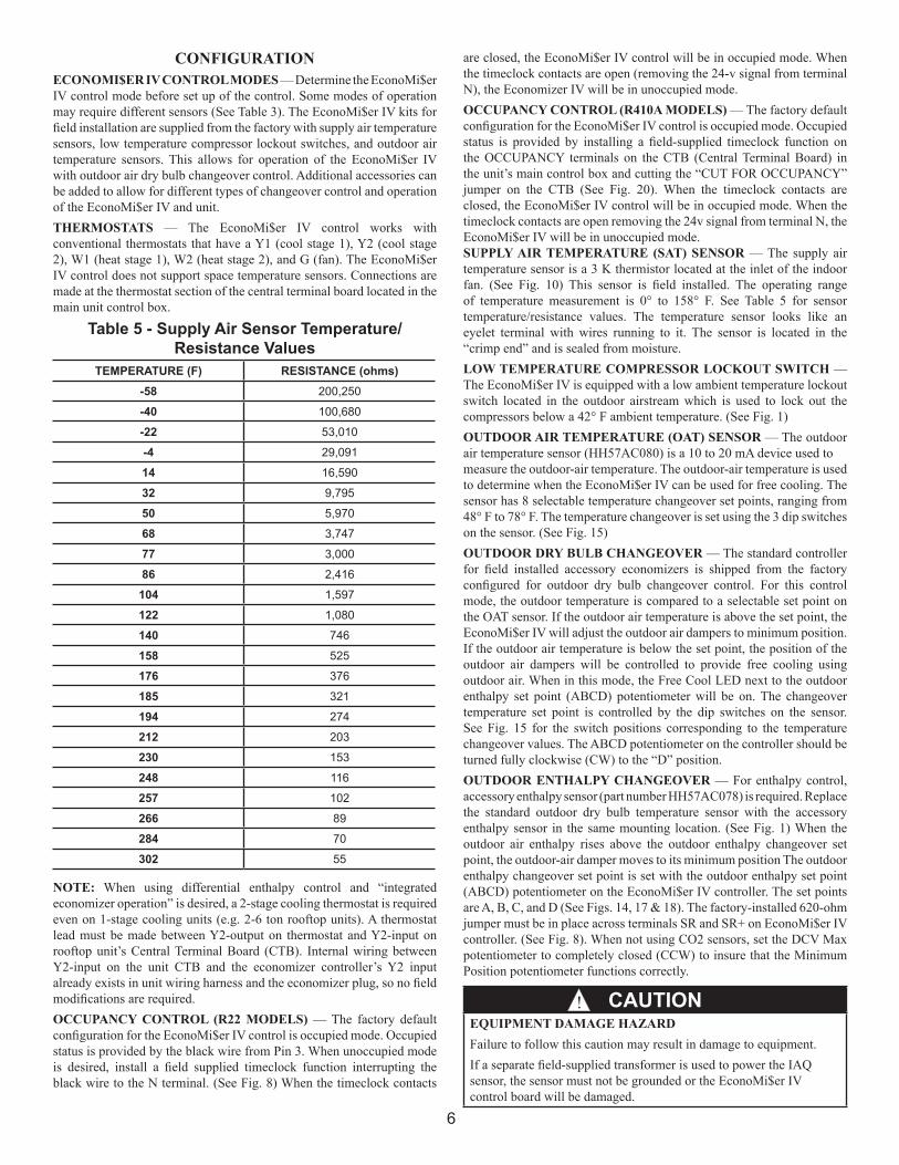
CONFIGURATIONECONOMI$ER IV CONTROL MODES — Determine the EconoMi$er IV control mode before set up of the control. Some modes of operation may require different sensors (See Table 3). The EconoMi$er IV kits for field installation are supplied from the factory with supply air temperature sensors, low temperature compressor lockout switches, and outdoor air temperature sensors. This allows for operation of the EconoMi$er IV with outdoor air dry bulb changeover control. Additional accessories can be added to allow for different types of changeover control and operation of the EconoMi$er IV and unit.THERMOSTATS — The EconoMi$er IV control works with conventional thermostats that have a Y1 (cool stage 1), Y2 (cool stage 2), W1 (heat stage 1), W2 (heat stage 2), and G (fan). The EconoMi$er IV control does not support space temperature sensors. Connections are made at the thermostat section of the central terminal board located in the main unit control box.
Table 5 - Supply Air Sensor Temperature/Resistance Values
TEMPERATURE (F) RESISTANCE (ohms)-58 200,250
-40 100,680
-22 53,010
-4 29,091
14 16,590
32 9,795
50 5,970
68 3,747
77 3,000
86 2,416
104 1,597
122 1,080
140 746
158 525
176 376
185 321
194 274
212 203
230 153
248 116
257 102
266 89
284 70
302 55
NOTE: When using differential enthalpy control and “integrated economizer operation” is desired, a 2-stage cooling thermostat is required even on 1-stage cooling units (e.g. 2-6 ton rooftop units). A thermostat lead must be made between Y2-output on thermostat and Y2-input on rooftop unit’s Central Terminal Board (CTB). Internal wiring between Y2-input on the unit CTB and the economizer controller’s Y2 input already exists in unit wiring harness and the economizer plug, so no field modifications are required.OCCUPANCY CONTROL (R22 MODELS) — The factory default configuration for the EconoMi$er IV control is occupied mode. Occupied status is provided by the black wire from Pin 3. When unoccupied mode is desired, install a field supplied timeclock function interrupting the black wire to the N terminal. (See Fig. 8) When the timeclock contacts
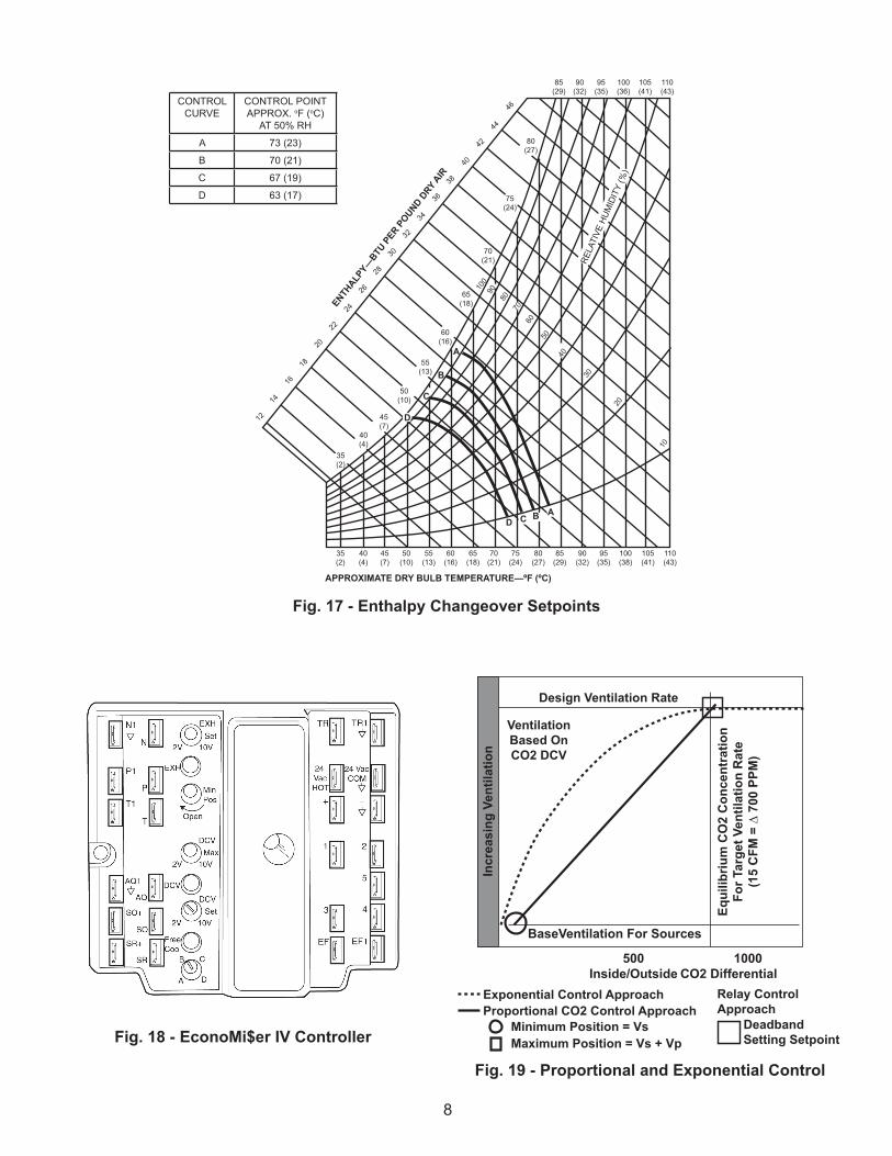
are closed, the EconoMi$er IV control will be in occupied mode. When the timeclock contacts are open (removing the 24-v signal from terminal N), the Economizer IV will be in unoccupied mode.OCCUPANCY CONTROL (R410A MODELS) — The factory default configuration for the EconoMi$er IV control is occupied mode. Occupied status is provided by installing a field-supplied timeclock function on the OCCUPANCY terminals on the CTB (Central Terminal Board) in the unit’s main control box and cutting the “CUT FOR OCCUPANCY” jumper on the CTB (See Fig. 20). When the timeclock contacts are closed, the EconoMi$er IV control will be in occupied mode. When the timeclock contacts are open removing the 24v signal from terminal N, the EconoMi$er IV will be in unoccupied mode.SUPPLY AIR TEMPERATURE (SAT) SENSOR — The supply air temperature sensor is a 3 K thermistor located at the inlet of the indoor fan. (See Fig. 10) This sensor is field installed. The operating range of temperature measurement is 0° to 158° F. See Table 5 for sensor temperature/resistance values. The temperature sensor looks like an eyelet terminal with wires running to it. The sensor is located in the “crimp end” and is sealed from moisture. LOW TEMPERATURE COMPRESSOR LOCKOUT SWITCH — The EconoMi$er IV is equipped with a low ambient temperature lockout switch located in the outdoor airstream which is used to lock out the compressors below a 42° F ambient temperature. (See Fig. 1)OUTDOOR AIR TEMPERATURE (OAT) SENSOR — The outdoor air temperature sensor (HH57AC080) is a 10 to 20 mA device used tomeasure the outdoor-air temperature. The outdoor-air temperature is used to determine when the EconoMi$er IV can be used for free cooling. The sensor has 8 selectable temperature changeover set points, ranging from 48° F to 78° F. The temperature changeover is set using the 3 dip switches on the sensor. (See Fig. 15) OUTDOOR DRY BULB CHANGEOVER — The standard controller for field installed accessory economizers is shipped from the factory configured for outdoor dry bulb changeover control. For this control mode, the outdoor temperature is compared to a selectable set point on the OAT sensor. If the outdoor air temperature is above the set point, the EconoMi$er IV will adjust the outdoor air dampers to minimum position. If the outdoor air temperature is below the set point, the position of the outdoor air dampers will be controlled to provide free cooling using outdoor air. When in this mode, the Free Cool LED next to the outdoor enthalpy set point (ABCD) potentiometer will be on. The changeover temperature set point is controlled by the dip switches on the sensor. See Fig. 15 for the switch positions corresponding to the temperature changeover values. The ABCD potentiometer on the controller should be turned fully clockwise (CW) to the “D” position.OUTDOOR ENTHALPY CHANGEOVER — For enthalpy control, accessory enthalpy sensor (part number HH57AC078) is required. Replace the standard outdoor dry bulb temperature sensor with the accessory enthalpy sensor in the same mounting location. (See Fig. 1) When the outdoor air enthalpy rises above the outdoor enthalpy changeover set point, the outdoor-air damper moves to its minimum position The outdoor enthalpy changeover set point is set with the outdoor enthalpy set point (ABCD) potentiometer on the EconoMi$er IV controller. The set points are A, B, C, and D (See Figs. 14, 17 & 18). The factory-installed 620-ohm jumper must be in place across terminals SR and SR+ on EconoMi$er IV controller. (See Fig. 8). When not using CO2 sensors, set the DCV Max potentiometer to completely closed (CCW) to insure that the Minimum Position potentiometer functions correctly.
CAUTIONEQUIPMENT DAMAGE HAZARDFailure to follow this caution may result in damage to equipment.If a separate field-supplied transformer is used to power the IAQ sensor, the sensor must not be grounded or the EconoMi$er IV control board will be damaged.
!
7
1
Selectable Temperature Options
N1
N
P1
T1
AQ1
SO+
SR+
SR
SO
AQ
T
P
2V 10VSet
EXH
EXH
MinPos
Open
2V 10VMax
DCV
DCV
FREECOOL
DCV
Set10V2V
B
A D
C
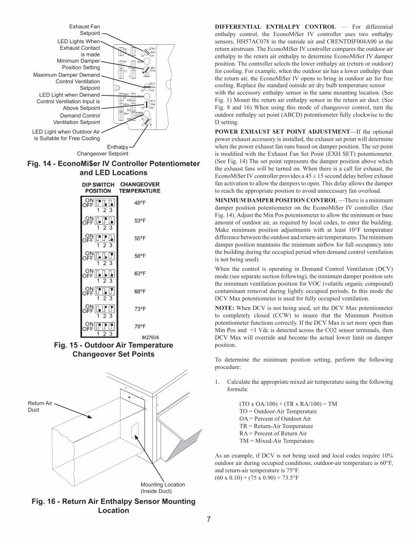
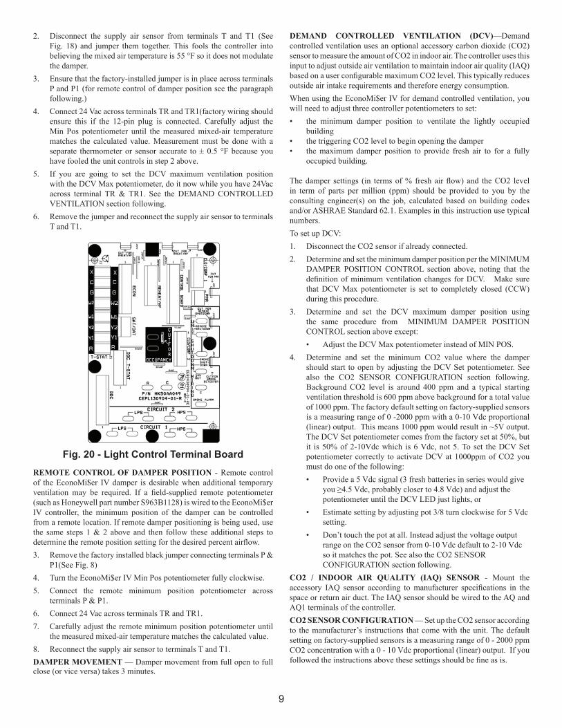
Fig. 14 - EconoMi$er IV Controller Potentiometer and LED Locations
Exhaust FanSetpoint
LED Lights WhenExhaust Contact
is madeMinimum Damper
Position SettingMaximum Damper Demand
Control VentilationSetpoint
LED Light when Demand Control Ventilation Input is
Above SetpointDemand Control
Ventilation Setpoint
LED Light when Outdoor Air is Suitable for Free Cooling
EnthalpyChangeover Setpoint
Fig. 16 - Return Air Enthalpy Sensor Mounting Location
Fig. 15 - Outdoor Air TemperatureChangeover Set Points
Mounting Location(Inside Duct)
Return AirDuct
DIFFERENTIAL ENTHALPY CONTROL — For differential enthalpy control, the EconoMi$er IV controller uses two enthalpy sensors, HH57AC078 in the outside air and CRENTDIF004A00 in the return airstream. The EconoMi$er IV controller compares the outdoor air enthalpy to the return air enthalpy to determine EconoMi$er IV damper position. The controller selects the lower enthalpy air (return or outdoor) for cooling. For example, when the outdoor air has a lower enthalpy than the return air, the EconoMi$er IV opens to bring in outdoor air for free cooling. Replace the standard outside air dry bulb temperature sensorwith the accessory enthalpy sensor in the same mounting location. (See Fig. 1) Mount the return air enthalpy sensor in the return air duct. (See Fig. 8 and 16) When using this mode of changeover control, turn the outdoor enthalpy set point (ABCD) potentiometer fully clockwise to the D setting.POWER EXHAUST SET POINT ADJUSTMENT—If the optional power exhaust accessory is installed, the exhaust set point will determine when the power exhaust fan runs based on damper position. The set point is modified with the Exhaust Fan Set Point (EXH SET) potentiometer. (See Fig. 14) The set point represents the damper position above which the exhaust fans will be turned on. When there is a call for exhaust, the EconoMi$er IV controller provides a 45 ± 15 second delay before exhaust fan activation to allow the dampers to open. This delay allows the damper to reach the appropriate position to avoid unnecessary fan overload.MINIMUM DAMPER POSITION CONTROL —There is a minimum damper position potentiometer on the EconoMi$er IV controller. (See Fig. 14). Adjust the Min Pos potentiometer to allow the minimum or base amount of outdoor air, as required by local codes, to enter the building. Make minimum position adjustments with at least 10°F temperature difference between the outdoor and return-air temperatures. The minimum damper position maintains the minimum airflow for full occupancy into the building during the occupied period when demand control ventilation is not being used).When the control is operating in Demand Control Ventilation (DCV) mode (see separate section following), the minimum damper position sets the minimum ventilation position for VOC (volatile organic compound) contaminant removal during lightly occupied periods. In this mode the DCV Max potentiometer is used for fully occupied ventilation.NOTE: When DCV is not being used, set the DCV Max potentiometer to completely closed (CCW) to insure that the Minimum Position potentiometer functions correctly. If the DCV Max is set more open than Min Pos and <1 Vdc is detected across the CO2 sensor terminals, then DCV Max will override and become the actual lower limit on damper position.
To determine the minimum position setting, perform the following procedure:
1. Calculate the appropriate mixed air temperature using the following formula:
(TO x OA/100) + (TR x RA/100) = TM TO = Outdoor-Air Temperature OA = Percent of Outdoor Air TR = Return-Air Temperature RA = Percent of Return Air TM = Mixed-Air Temperature
As an example, if DCV is not being used and local codes require 10% outdoor air during occupied conditions, outdoor-air temperature is 60°F, and return-air temperature is 75°F.(60 x 0.10) + (75 x 0.90) = 73.5°F
8
Fig. 17 - Enthalpy Changeover Setpoints
Fig. 18 - EconoMi$er IV Controller
35(2)
35(2)
12
14
16
18
20
22
24
26
28
30
32
34
36
38
40
42
44
46
100
9080
7060
50
40
30
20
10
40(4)
40(4)
45(7)
D C B A
D
B
C
A
45(7)
50(10)
50(10)
55(13)
60(16)
65(18)
70(21)
75(24)
80(27)
85(29)
90(32)
95(35)
100(38)
105(41)
110(43)
55(13)
60(16)
65(18)
70(21)
75(24)
80(27)
85(29)
90(32)
95(35)
100(36)
105(41)
110(43)
RELA
TIVE
HUM
IDIT
Y (%
)
APPROXIMATE DRY BULB TEMPERATURE—ºF (ºC)
ENTHALP
Y—BTU
PER P
OUND DRY A
IR
CONTROL CURVE
CONTROL POINTAPPROX. oF (oC)
AT 50% RH
A 73 (23)
B 70 (21)
C 67 (19)
D 63 (17)
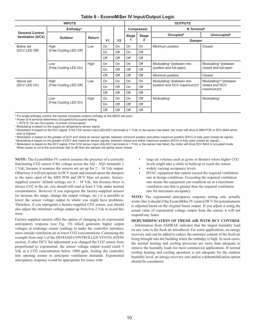
Fig. 19 - Proportional and Exponential Control
Design Ventilation Rate
Exponential Control ApproachProportional CO2 Control Approach
Minimum Position = VsMaximum Position = Vs + Vp
Relay ControlApproach
DeadbandSetting Setpoint
BaseVentilation For Sources
500Inside/Outside
1000CO2 Differential
Equi
libriu
m C
O2
Con
cent
ratio
nFo
r Tar
get V
entil
atio
n R
ate
(15
CFM
= ∆
700
PPM
)
Incr
easi
ng V
entil
atio
n
VentilationBased OnCO2 DCV
9
2. Disconnect the supply air sensor from terminals T and T1 (See Fig. 18) and jumper them together. This fools the controller into believing the mixed air temperature is 55 °F so it does not modulate the damper.
3. Ensure that the factory-installed jumper is in place across terminals P and P1 (for remote control of damper position see the paragraph following.)
4. Connect 24 Vac across terminals TR and TR1(factory wiring should ensure this if the 12-pin plug is connected. Carefully adjust the Min Pos potentiometer until the measured mixed-air temperature matches the calculated value. Measurement must be done with a separate thermometer or sensor accurate to ± 0.5 °F because you have fooled the unit controls in step 2 above.
5. If you are going to set the DCV maximum ventilation position with the DCV Max potentiometer, do it now while you have 24Vac across terminal TR & TR1. See the DEMAND CONTROLLED VENTILATION section following.
6. Remove the jumper and reconnect the supply air sensor to terminals T and T1.
Fig. 20 - Light Control Terminal BoardREMOTE CONTROL OF DAMPER POSITION - Remote control of the EconoMi$er IV damper is desirable when additional temporary ventilation may be required. If a field-supplied remote potentiometer (such as Honeywell part number S963B1128) is wired to the EconoMi$er IV controller, the minimum position of the damper can be controlled from a remote location. If remote damper positioning is being used, use the same steps 1 & 2 above and then follow these additional steps to determine the remote position setting for the desired percent airflow.3. Remove the factory installed black jumper connecting terminals P &
P1(See Fig. 8) 4. Turn the EconoMi$er IV Min Pos potentiometer fully clockwise.5. Connect the remote minimum position potentiometer across
terminals P & P1.6. Connect 24 Vac across terminals TR and TR1.7. Carefully adjust the remote minimum position potentiometer until
the measured mixed-air temperature matches the calculated value. 8. Reconnect the supply air sensor to terminals T and T1.DAMPER MOVEMENT — Damper movement from full open to full close (or vice versa) takes 3 minutes.
DEMAND CONTROLLED VENTILATION (DCV)—Demand controlled ventilation uses an optional accessory carbon dioxide (CO2) sensor to measure the amount of CO2 in indoor air. The controller uses this input to adjust outside air ventilation to maintain indoor air quality (IAQ) based on a user configurable maximum CO2 level. This typically reduces outside air intake requirements and therefore energy consumption. When using the EconoMi$er IV for demand controlled ventilation, you will need to adjust three controller potentiometers to set:• the minimum damper position to ventilate the lightly occupied
building• the triggering CO2 level to begin opening the damper • the maximum damper position to provide fresh air to for a fully
occupied building.
The damper settings (in terms of % fresh air flow) and the CO2 level in term of parts per million (ppm) should be provided to you by the consulting engineer(s) on the job, calculated based on building codes and/or ASHRAE Standard 62.1. Examples in this instruction use typical numbers. To set up DCV:1. Disconnect the CO2 sensor if already connected.2. Determine and set the minimum damper position per the MINIMUM
DAMPER POSITION CONTROL section above, noting that the definition of minimum ventilation changes for DCV. Make sure that DCV Max potentiometer is set to completely closed (CCW) during this procedure.
3. Determine and set the DCV maximum damper position using the same procedure from MINIMUM DAMPER POSITION CONTROL section above except:
• Adjust the DCV Max potentiometer instead of MIN POS. 4. Determine and set the minimum CO2 value where the damper
should start to open by adjusting the DCV Set potentiometer. See also the CO2 SENSOR CONFIGURATION section following. Background CO2 level is around 400 ppm and a typical starting ventilation threshold is 600 ppm above background for a total value of 1000 ppm. The factory default setting on factory-supplied sensors is a measuring range of 0 -2000 ppm with a 0-10 Vdc proportional (linear) output. This means 1000 ppm would result in ~5V output. The DCV Set potentiometer comes from the factory set at 50%, but it is 50% of 2-10Vdc which is 6 Vdc, not 5. To set the DCV Set potentiometer correctly to activate DCV at 1000ppm of CO2 you must do one of the following:
• Provide a 5 Vdc signal (3 fresh batteries in series would give you ≥4.5 Vdc, probably closer to 4.8 Vdc) and adjust the potentiometer until the DCV LED just lights, or
• Estimate setting by adjusting pot 3/8 turn clockwise for 5 Vdc setting. • Don’t touch the pot at all. Instead adjust the voltage output
range on the CO2 sensor from 0-10 Vdc default to 2-10 Vdc so it matches the pot. See also the CO2 SENSOR CONFIGURATION section following.
CO2 / INDOOR AIR QUALITY (IAQ) SENSOR - Mount the accessory IAQ sensor according to manufacturer specifications in the space or return air duct. The IAQ sensor should be wired to the AQ and AQ1 terminals of the controller. CO2 SENSOR CONFIGURATION — Set up the CO2 sensor according to the manufacturer’s instructions that come with the unit. The default setting on factory-supplied sensors is a measuring range of 0 - 2000 ppm CO2 concentration with a 0 - 10 Vdc proportional (linear) output. If you followed the instructions above these settings should be fine as is.
10
NOTE: The EconoMi$er IV control assumes the presence of a correctly functioning CO2 sensor if the voltage across the AQ – AQ1 terminals ≥ 1 Vdc, because it assumes the sensors are set up for 2 – 10 Vdc output. Otherwise it will not operate in DCV mode and instead opens the dampers to the more open of the MIN POS and DCV Max set points. factory-supplied sensors’ default settings are 0 – 10 Vdc, but because there is always CO2 in the air, you should still read at least 2 Vdc under normal circumstances. However if you reprogram the factory-supplied sensors (to increase the range, change the output voltage, etc.) it is possible to lower the sensor voltage output to where you might have problems. Therefore, if you reprogram a factory-supplied CO2 sensor, you should also adjust the minimum voltage output up from 0 to 2 Vdc to avoid this issue.Factory-supplied sensors offer the option of changing to an exponential anticipatory response (see Fig. 19) which generates higher output voltages at midrange sensor readings to make the controller introduce more outside ventilation air at lower CO2 concentrations. Continuing the example from step 3 of the DEMAND CONTROLLED VENTILATION section, if after DCV Set adjustment you changed the CO2 sensor from proportional to exponential, the sensor voltage output would reach 5 Vdc at a CO2 concentration below 1000 ppm, fooling the controller into opening sooner to anticipate ventilation demands. Exponential anticipatory response would be appropriate for zones with:
a For single enthalpy control, the module compares outdoor enthalpy to the ABCD set point.b Power at N terminal determines Occupied/Unoccupied setting: • W7212: 24 vac (Occupied), no power (Unoccupied).c Modulating is based on the supply-air temperature sensor signal.d Modulation is based on the DCV signal. If the CO2 sensor input (AQ-AQ1) terminals is < 1Vdc or the sensor has failed, the motor will drive to MIN POS or DCV MAX which ever is highest.e Modulation is based on the greater of DCV and mixed air sensor signals, between minimum position and either maximum position (DCV) or fully open (mixed air signal).f Modulating is based on the greater of DCV and mixed air sensor signals, between closed and wither maximum position (DCV) or fully open (mixed air signal).g Modulation is based on the DCV signal, if the CO2 sensor input (AQ-AQ1) terminals is < 1Vdc or the sensor has failed, the motor will drive DCV MAX in occupied mode. When power is cut to the economizer (fan is off) then the damper will spring return closed.
INPUTS OUTPUTS
Demand ControlVentilation (DCV)
Enthalpya
Y1 Y2
Compressor N Terminalb
Outdoor Return Stage1
Stage2
Occupiedb Unoccupiedb
DamperBelow set(DCV LED Off)
High(Free Cooling LED Off)
Low On On On On Minimum position Closed
On Off On Off
Off Off Off Off
Low(Free Cooling LED On)
High On On On Off Modulatingc (between min. position and full-open)
Modulatingc (between closed and full-openOn Off Off Off
Off Off Off Off Minimum position Closed
Above set(DCV LED On)
High(Free Cooling LED Off)
Low On On On On Modulatingd (between min.position and DCV maximum)††
Modulatingd,g (betweenclosed and DCVmaximum)††
On Off On Off
Off Off Off Off
Low(Free Cooling LED On)
High On On On Off Modulatinge Modulatingf
On Off Off Off
Off Off Off Off
Table 6 - EconoMi$er IV Input/Output Logic
• large air volumes such as gyms or theaters where higher CO2 levels might take a while to build up or reach the sensor.
• widely varying occupancy levels • HVAC equipment that cannot exceed the required ventilation
rate at design conditions. Exceeding the required ventilation rate means the equipment can condition air at a maximum ventilation rate that is greater than the required ventilation rate for maximum occupancy.
NOTE: The exponential anticipatory response setting only actually works like it should if the EconoMi$er IV control DCV Set potentiometer is adjusted based on the original linear output. If you adjust it using the actual value of exponential voltage output from the sensor, it will not respond any faster. DEHUMIDIFICATION OF FRESH AIR WITH DCV CONTROL —Information from ASHRAE indicates that the largest humidity load on any zone is the fresh air introduced. For some applications, an energy recovery unit can be added to reduce the moisture content of the fresh air being brought into the building when the enthalpy is high. In most cases, the normal heating and cooling processes are more than adequate to remove the humidity loads for most commercial applications. If normal rooftop heating and cooling operation is not adequate for the outdoor humidity level, an energy recovery unit and/or a dehumidification option should be considered.
11
OPERATIONWhen outside air temperatures are below return air temperatures the possibility exists for “free cooling,” similar to opening a window instead of turning on your air conditioner. The EconoMi$er opens outdoor air dampers to admit cool outside air to the inlet of the supply air fan instead of activating the unit’s compressor(s). This opening is controlled by a variety of standard and optional control strategies based on temperature, enthalpy and/or CO2 content of indoor and/or outdoor air. Relief dampers dump relatively hotter return air outdoors at the same time, optionally assisted by the power exhaust accessory. See Table 6 for a summary of controller logic.SEQUENCE OF OPERATION—For EconoMi$er IV operation, there must be a thermostat call for the fan (G). This will move the damper to its minimum position (as controlled by the MIN POS potentiometer) during the occupied mode. When outside air conditions are such that free cooling is not available, the compressor will be controlled by the thermostat. If free cooling can be used, as determined from the appropriate sensors (dry bulb temperature, enthalpy, or differential enthalpy) and changeover control schedule, a call for cooling (Y1 closes at the thermostat) will cause the EconoMi$er IV control to provide a 50° to 55°F supply-air into the zone. As the supply air temperature (SAT) fluctuates above 55°F concurrent with Compressor 1 operation, the low ambient lockout thermostat will block compressor operation with EconoMi$er IV operation below 42oF outside-air temperature.If a field-installed accessory CO2 sensor is connected to the EconoMi$er IV control, a demand controlled ventilation strategy will begin to operate in parallel with the free cooling strategy. As the CO2 level in the zone increases above the CO2 set point position (as controlled by the DCV set potentiometer), the position of the damper will be increased proportionally to the DCV Max position (as controlled by the DCV Max potentiometer). As the CO2 level decreases because of the increase in fresh air, the outdoor-air damper will be proportionally closed back down to the minimum open position. Damper position will follow the higher demand condition from the DCV mode or free cooling mode.
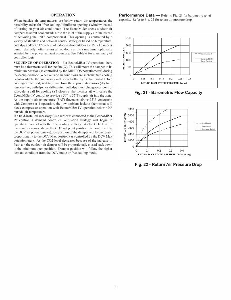
Performance Data — Refer to Fig. 21 for barometric relief capacity. Refer to Fig. 22 for return air pressure drop.
Fig. 21 - Barometric Flow Capacity
Fig. 22 - Return Air Pressure Drop
0
500
1000
1500
2000
2500
0 0.05 0.1 0.15 0.2 0.25 0.3
RE
LIE
F FL
OW
(CFM
)
RETURN DUCT STATIC PRESSURE (in. wg)
Small Cabinet
Large and Extra Large Cabinet
0
1000
2000
3000
4000
5000
6000
0 0.1 0.2 0.3 0.4
RE
TU
RN
AIR
FL
OW
(CFM
)
RETURN DUCT STATIC PRESSURE DROP (in. wg)
Small Cabinet
Large Cabinet
Extra Large Cabinet
12
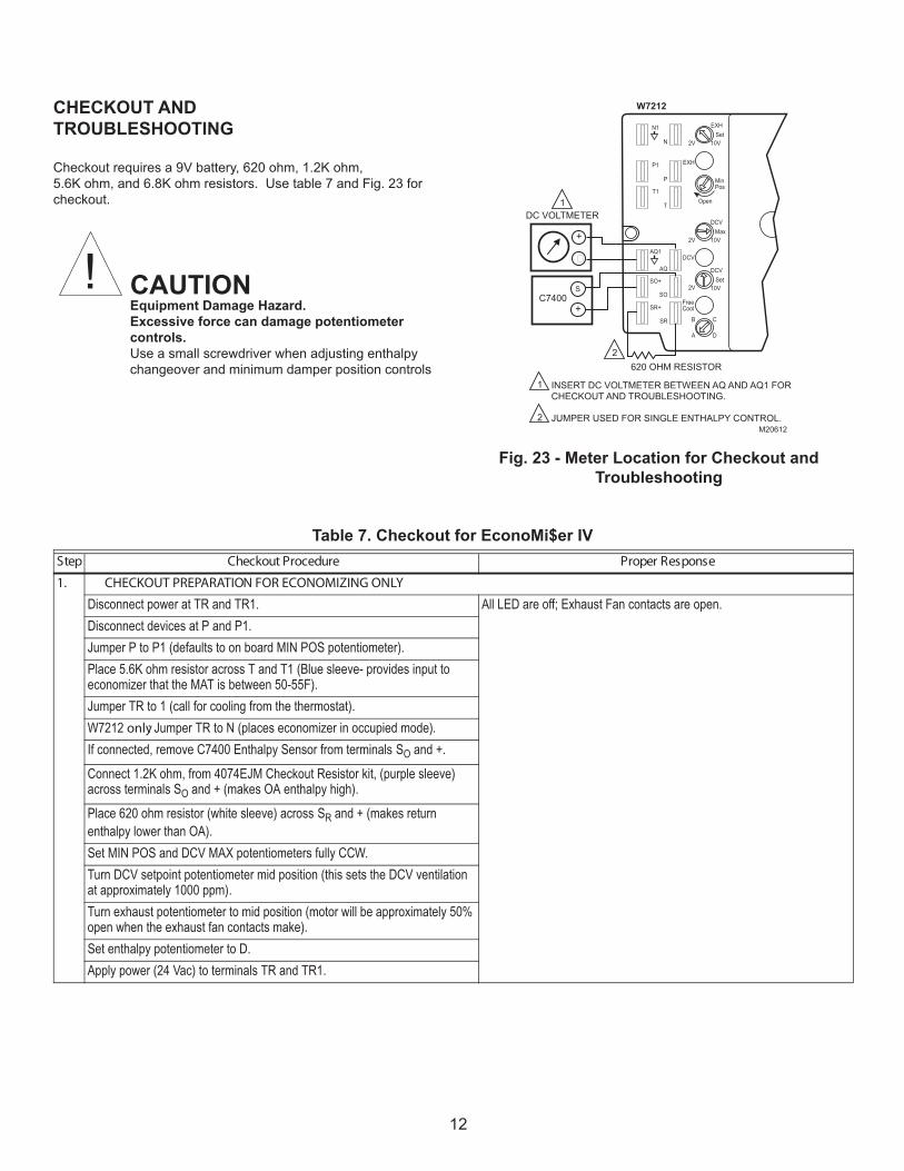
Fig. 23 - Meter Location for Checkout andTroubleshooting
M20612
N1
P1
T1
N 2V
2V
2V
B
A
SR
SO
AQ
C
D
FreeCool
10V
EXH
DCV
EXHSet
10V
DCVMax
10V
DCVSet
MinPos
Open
P
T
AQ1
SO+
SR+
1
2
DC VOLTMETER
620 OHM RESISTOR
W7212
+
S
+C7400
1
2
INSERT DC VOLTMETER BETWEEN AQ AND AQ1 FORCHECKOUT AND TROUBLESHOOTING.
JUMPER USED FOR SINGLE ENTHALPY CONTROL.
ecorP tuokcehC petS esnopseR reporP erud
1. CHECKOUT PREPARATION FOR ECONOMIZING ONLY
.nepo era stcatnoc naF tsuahxE ;ffo era DEL llA .1RT dna RT ta rewop tcennocsiDDisconnect devices at P and P1.Jumper P to P1 (defaults to on board MIN POS potentiometer).Place 5.6K ohm resistor across T and T1 (Blue sleeve- provides input to economizer that the MAT is between 50-55F).Jumper TR to 1 (call for cooling from the thermostat).W7212 only: Jumper TR to N (places economizer in occupied mode).If connected, remove C7400 Enthalpy Sensor from terminals SO and +. Connect 1.2K ohm, from 4074EJM Checkout Resistor kit, (purple sleeve) across terminals SO and + (makes OA enthalpy high).Place 620 ohm resistor (white sleeve) across SR and + (makes return enthalpy lower than OA).Set MIN POS and DCV MAX potentiometers fully CCW.Turn DCV setpoint potentiometer mid position (this sets the DCV ventilation at approximately 1000 ppm).Turn exhaust potentiometer to mid position (motor will be approximately 50% open when the exhaust fan contacts make).Set enthalpy potentiometer to D.Apply power (24 Vac) to terminals TR and TR1.
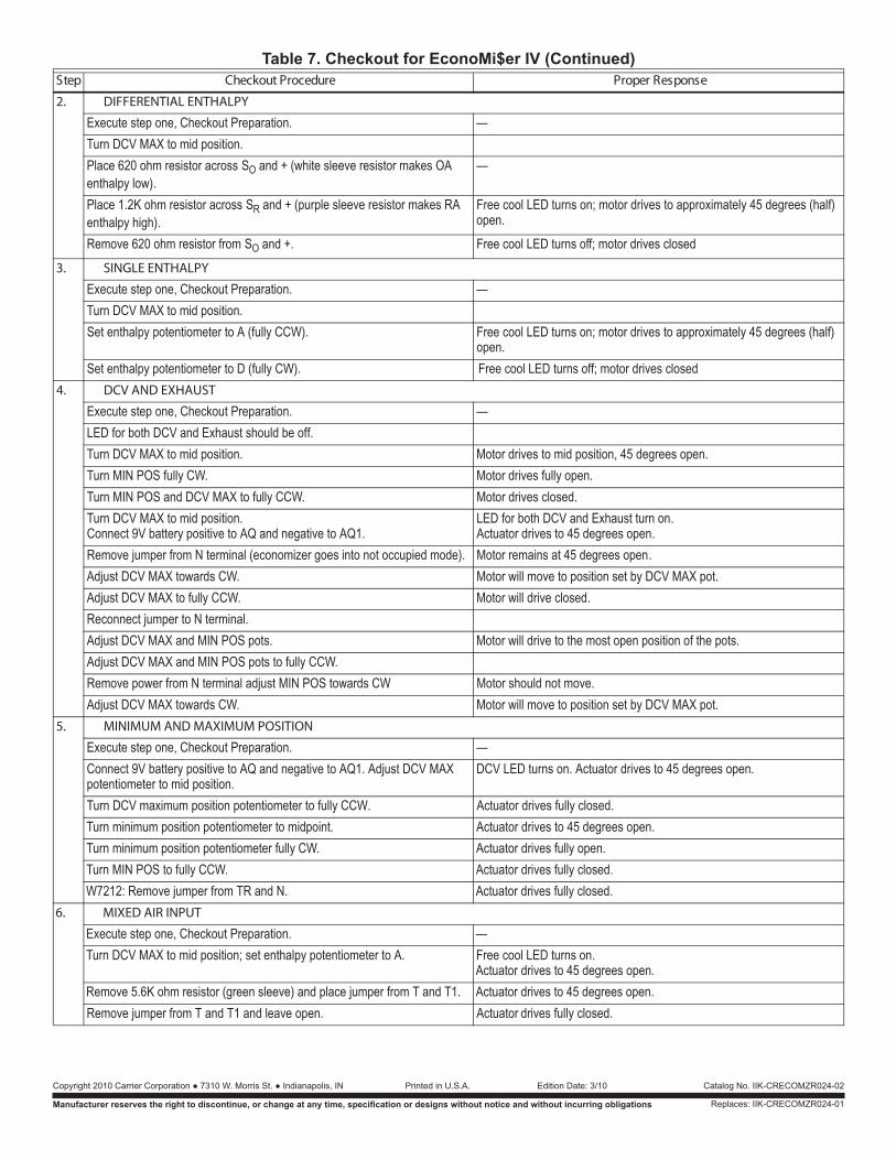
Table 7. Checkout for EconoMi$er IV
CHECKOUT AND TROUBLESHOOTING
Checkout requires a 9V battery, 620 ohm, 1.2K ohm,5.6K ohm, and 6.8K ohm resistors. Use table 7 and Fig. 23 for checkout.
! CAUTIONEquipment Damage Hazard.Excessive force can damage potentiometercontrols.Use a small screwdriver when adjusting enthalpychangeover and minimum damper position controls
13
2. DIFFERENTIAL ENTHALPY
—.noitaraperP tuokcehC ,eno pets etucexETurn DCV MAX to mid position.Place 620 ohm resistor across SO and + (white sleeve resistor makes OA enthalpy low).
—
Place 1.2K ohm resistor across SR and + (purple sleeve resistor makes RA enthalpy high).
Free cool LED turns on; motor drives to approximately 45 degrees (half) open.
Remove 620 ohm resistor from SO desolc sevird rotom ;ffo snrut DEL looc eerF .+ dna 3. SINGLE ENTHALPY
—.noitaraperP tuokcehC ,eno pets etucexETurn DCV MAX to mid position.
)flah( seerged 54 yletamixorppa ot sevird rotom ;no snrut DEL looc eerF .)WCC ylluf( A ot retemoitnetop yplahtne teSopen.
Set enthalpy potentiometer to D (fully CW). Free cool LED turns off; motor drives closed4. DCV AND EXHAUST
—.noitaraperP tuokcehC ,eno pets etucexELED for both DCV and Exhaust should be off.
.nepo seerged 54 ,noitisop dim ot sevird rotoM.noitisop dim ot XAM VCD nruT.nepo ylluf sevird rotoM.WC ylluf SOP NIM nruT
Turn MIN POS and DCV MAX to fu .desolc sevird rotoM.WCC yllTurn DCV MAX to mid position.Connect 9V battery positive to AQ and negative to AQ1.
LED for both DCV and Exhaust turn on.Actuator drives to 45 degrees open.
Remove jumper from N terminal (economizer goes into not occupied mode). Motor remains at 45 degrees open. lliw rotoM.WC sdrawot XAM VCD tsujdA move to position set by DCV MAX pot.
.desolc evird lliw rotoM.WCC ylluf ot XAM VCD tsujdAReconnect jumper to N terminal.
.stop eht fo noitisop nepo tsom eht ot evird lliw rotoM.stop SOP NIM dna XAM VCD tsujdAAdjust DCV MAX and MIN POS pots to fully CCW.Remove power from N terminal adjust MIN POS towards CW Motor should not move.
lliw rotoM.WC sdrawot XAM VCD tsujdA move to position set by DCV MAX pot.5. MINIMUM AND MAXIMUM POSITION
—.noitaraperP tuokcehC ,eno pets etucexEConnect 9V battery positive to AQ and negative to AQ1. Adjust DCV MAX potentiometer to mid position.
DCV LED turns on. Actuator drives to 45 degrees open.
Turn DCV maximum position potentiometer to fully CCW. Actuator drives fully closed..nepo seerged 54 ot sevird rotautcA .tniopdim ot retemoitnetop noitisop muminim nruT
.nepo ylluf sevird rotautcA .WC ylluf retemoitnetop noitisop muminim nruT.desolc ylluf sevird rotautcA .WCC ylluf ot SOP NIM nruT.desolc ylluf sevird rotautcA.N dna RT morf repmuj evomeR :2127W
6. MIXED AIR INPUT
—.noitaraperP tuokcehC ,eno pets etucexETurn DCV MAX to mid position; set enthalpy potentiometer to A. Free cool LED turns on.
Actuator drives to 45 degrees open.Remove 5.6K ohm resistor (green sleeve) and place jumper from T and T1. Actuator drives to 45 degrees open.
.desolc ylluf sevird rotautcA .nepo evael dna 1T dna T morf repmuj evomeR
ecorP tuokcehC petS esnopseR reporP erudTable 7. Checkout for EconoMi$er IV (Continued)
Copyright 2010 Carrier Corporation ● 7310 W. Morris St. ● Indianapolis, IN
Manufacturer reserves the right to discontinue, or change at any time, specification or designs without notice and without incurring obligations
Catalog No. IIK-CRECOMZR024-02Printed in U.S.A. Edition Date: 3/10
Replaces: IIK-CRECOMZR024-01