Embed Size (px)
Citation preview
506859-01 Issue 1236 Page 1 of 32
The equipment covered in this manual is to be installed by trained and experienced service and installation technicians. Improper installation, modification, service, or use can cause electrical shock, fire, explosion, or other conditions which may cause personal injury, death, or property damage. Use appropriate safety gear including safety glasses and gloves when installing this equipment.
WARNING
Installation and servicing of air conditioning equipment can be hazardous due to internal refrigerant pressure and live electrical components. Only trained and qualified service personnel should install or service this equipment. Installation and service performed by unqualified persons can result in property damage, personal injury, or death.
WARNING
Sharp metal edges can cause injury. When installing the unit, use care to avoid sharp edges.
WARNING
INSTALLATION AND MAINTENANCE INSTRUCTIONS
4SCU 16/18LS SERIESSplit System Air Conditioner
These instructions must be read and understood completely before attempting installation.
Risk of electrical shock. Disconnect all remote power supplies before installing or servicing any portion of the system. Failure to disconnect power supplies can result in property damage, personal injury, or death.
WARNING TABLE OF CONTENTS
INSTALLATION ....................................................2
CONNECTION DIAGRAM .....................................4
START-UP ...........................................................14
OPERATION ........................................................17
ALERT CODE ......................................................21
MAINTENANCE ..................................................26
WARRANTY ........................................................31
Manufactured ByAllied Air Enterprises, Inc.
A Lennox International Inc. Company215 Metropolitan Drive
West Columbia, SC 29170
*P506859-01*
*p506859-01*
506859-01Issue 1236Page 2 of 32
INSTALLATION
Table 1
Torque Table
Figure 1
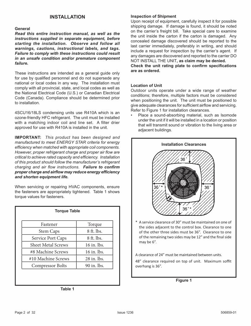
Installation Clearances
* A service clearance of 30” must be maintained on one of the sides adjacent to the control box. Clearance to one of the other three sides must be 36”. Clearance to one of the remaining two sides may be 12” and the final side may be 6”.
A clearance of 24” must be maintained between units.48” clearance required on top of unit. Maximum soffit overhang is 36”.
GeneralRead this entire instruction manual, as well as the instructions supplied in separate equipment, before starting the installation. Observe and follow all warnings, cautions, instructional labels, and tags. Failure to comply with these instructions could result in an unsafe condition and/or premature component failure.
These instructions are intended as a general guide only for use by qualified personnel and do not supersede any national or local codes in any way. The installation must comply with all provincial, state, and local codes as well as the National Electrical Code (U.S.) or Canadian Electrical Code (Canada). Compliance should be determined prior to installation.
4SCU16/18LS condensing units use R410A which is an ozone-friendly HFC refrigerant. The unit must be installed with a matching indoor coil and line set. A filter drier approved for use with R410A is installed in the unit.
IMPORTANT: This product has been designed and manufactured to meet ENERGY STAR criteria for energy efficiency when matched with appropriate coil components. However, proper refrigerant charge and proper air flow are critical to achieve rated capacity and efficiency. Installation of this product should follow the manufacturer’s refrigerant charging and air flow instructions. Failure to confirm proper charge and airflow may reduce energy efficiency and shorten equipment life.
When servicing or repairing HVAC components, ensure the fasteners are appropriately tightened. Table 1 shows torque values for fasteners.
Inspection of ShipmentUpon receipt of equipment, carefully inspect it for possible shipping damage. If damage is found, it should be noted on the carrier’s freight bill. Take special care to examine the unit inside the carton if the carton is damaged. Any concealed damage discovered should be reported to the last carrier immediately, preferably in writing, and should include a request for inspection by the carrier’s agent. If any damages are discovered and reported to the carrier DO NOT INSTALL THE UNIT, as claim may be denied.Check the unit rating plate to confirm specifications are as ordered.
Location of UnitOutdoor units operate under a wide range of weather conditions; therefore, multiple factors must be considered when positioning the unit. The unit must be positioned to give adequate clearances for sufficient airflow and servicing. Refer to Figure 1 for installation clearances.• Place a sound-absorbing material, such as Isomode
under the unit if it will be installed in a location or position that will transmit sound or vibration to the living area or adjacent buildings.
Fastener TorqueStem Caps 8 ft. lbs.
Service Port Caps 8 ft. lbs.Sheet Metal Screws 16 in. lbs.#8 Machine Screws 16 in. lbs.
#10 Machine Screws 28 in. lbs.Compressor Bolts 90 in. lbs.
506859-01 Issue 1236 Page 3 of 32
Roof MountingInstall unit at a minimum of 4” above surface of the roof. Locate the unit above a load bearing wall or area of the roof that can adequately support the unit. Consult local codes for rooftop applications.
Electrical WiringAll field wiring must be done in accordance with the National Electrical Code (NEC) recommendations, Canadian Electrical Code (CEC) and CSA Standards, or local codes, where applicable.
Refer to the furnace or blower coil installation instructions for additional wiring application diagrams and refer to unit rating plate for minimum circuit ampacity and maximum overcurrent protection size.
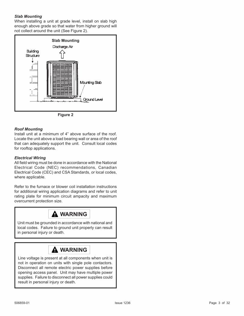
Slab MountingWhen installing a unit at grade level, install on slab high enough above grade so that water from higher ground will not collect around the unit (See Figure 2).
Line voltage is present at all components when unit is not in operation on units with single pole contactors. Disconnect all remote electric power supplies before opening access panel. Unit may have multiple power supplies. Failure to disconnect all power supplies could result in personal injury or death.
WARNING
Unit must be grounded in accordance with national and local codes. Failure to ground unit properly can result in personal injury or death.
WARNING
Figure 2
Slab Mounting
506859-01Issue 1236Page 4 of 32
1. Install line voltage power supply to unit from a properly sized disconnect switch. Any excess high voltage field wiring should be trimmed or secured away from the low voltage field wiring.
2. Ground unit at unit disconnect switch or to an earth ground. To facilitate conduit, a hole is in the bottom of the control box. Connect conduit to the control box using a proper conduit fitting. Units are approved for use only with copper conductors. 24V Class II circuit connections are made in the low voltage junction box. Refer to Figure 4 for high voltage field wiring diagram. A complete unit wiring diagram is located inside the unit control box cover and in the back of this document.
3. Install room thermostat on an inside wall that is not subject to drafts, direct sunshine, or other heat sources.
4. Install low voltage wiring from outdoor to indoor unit and from thermostat to indoor unit. (See Wire Diagram on page 29.)
5. Do not bundle any excess 24V control wire inside control box. Run control wire through installed wire tie and tighten wire tie to provide low voltage strain relief and to maintain seperation of field-installed low and high voltage circuits.
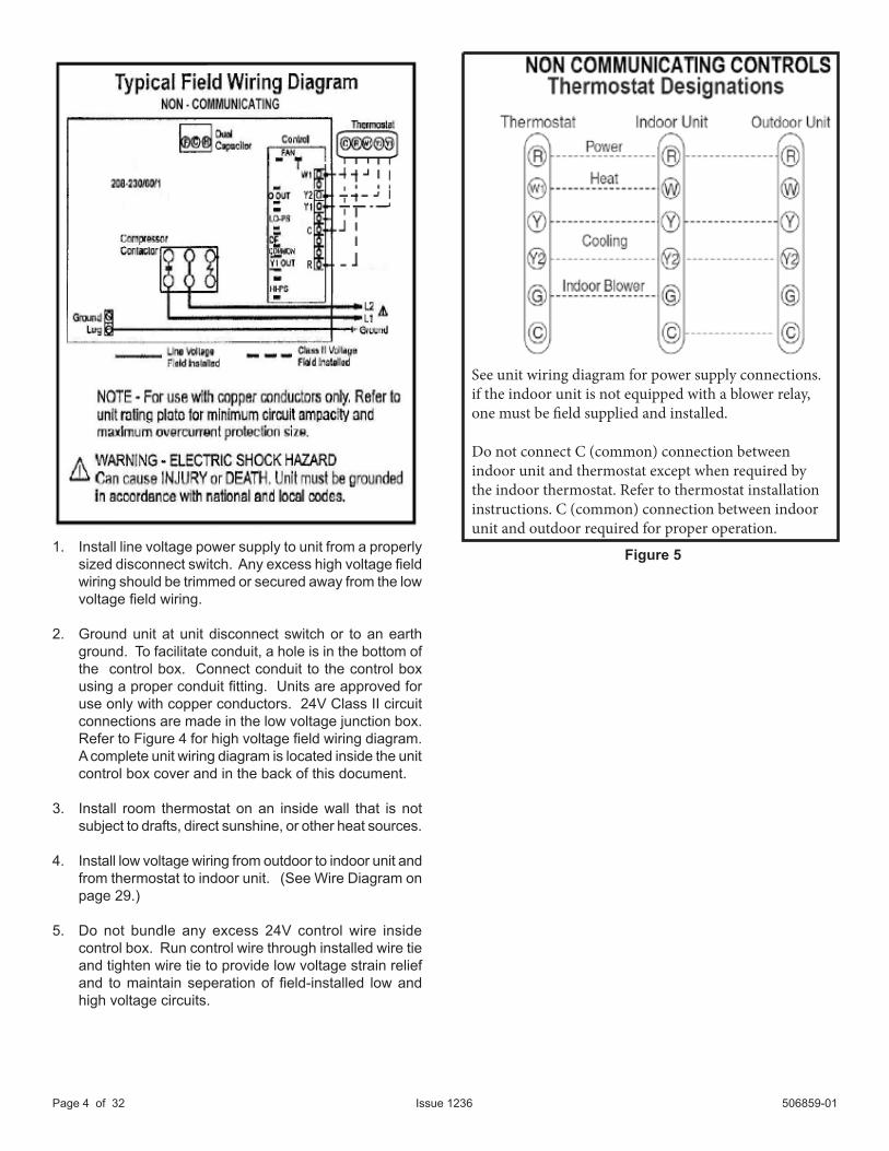
Figure 5
See unit wiring diagram for power supply connections.if the indoor unit is not equipped with a blower relay,one must be field supplied and installed.
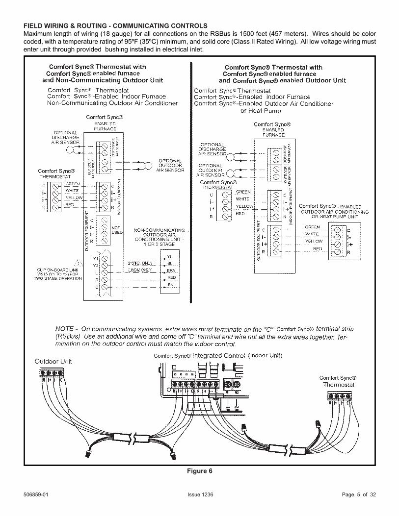
Do not connect C (common) connection betweenindoor unit and thermostat except when required bythe indoor thermostat. Refer to thermostat installationinstructions. C (common) connection between indoorunit and outdoor required for proper operation.
506859-01 Issue 1236 Page 5 of 32
FIELD WIRING & ROUTING - COMMUNICATING CONTROLSMaximum length of wiring (18 gauge) for all connections on the RSBus is 1500 feet (457 meters). Wires should be color coded, with a temperature rating of 95ºF (35ºC) minimum, and solid core (Class II Rated Wiring). All low voltage wiring must enter unit through provided bushing installed in electrical inlet.
Figure 6
506859-01Issue 1236Page 6 of 32
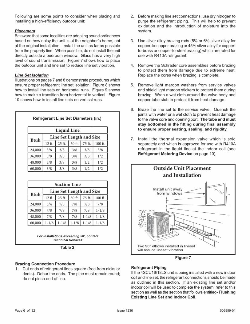
Install unit awayfrom windows
Two 90° elbows installed in linesetwill reduce lineset vibration
Figure 7Brazing Connection Procedure1. Cut ends of refrigerant lines square (free from nicks or
dents). Debur the ends. The pipe must remain round; do not pinch end of line.
Refrigerant PipingIf the 4SCU16/18LS unit is being installed with a new indoor coil and line set, the refrigerant connections should be made as outlined in this section. If an existing line set and/or indoor coil will be used to complete the system, refer to this section as well as the section that follows entitled- Flushing Existing Line Set and Indoor Coil.
2. Before making line set connections, use dry nitrogen to purge the refrigerant piping. This will help to prevent oxidation and the introduction of moisture into the system.
3. Use silver alloy brazing rods (5% or 6% silver alloy for copper-to-copper brazing or 45% silver alloy for copper-to-brass or copper-to-steel brazing) which are rated for use with R410A refrigerant.
4. Remove the Schrader core assemblies before brazing to protect them from damage due to extreme heat. Replace the cores when brazing is complete.
5. Remove light maroon washers from service valves and shield light maroon stickers to protect them during brazing. Wrap a wet cloth around the valve body and copper tube stub to protect it from heat damage.
6. Braze the line set to the service valve. Quench the joints with water or a wet cloth to prevent heat damage to the valve core and opening port. The tube end must stay bottomed in the fitting during final assembly to ensure proper seating, sealing, and rigidity.
7. Install the thermal expansion valve which is sold separately and which is approved for use with R410A refrigerant in the liquid line at the indoor coil (see Refrigerant Metering Device on page 10).
Following are some points to consider when placing and installing a high-efficiency outdoor unit:
PlacementBe aware that some localities are adopting sound ordinances based on how noisy the unit is at the neighbor’s home, not at the original installation. Install the unit as far as possible from the property line. When possible, do not install the unit directly outside a bedroom window. Glass has a very high level of sound transmission. Figure 7 shows how to place the outdoor unit and line set to reduce line set vibration.
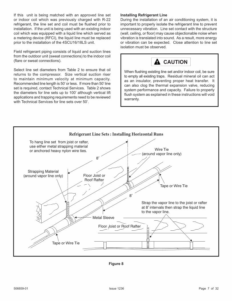
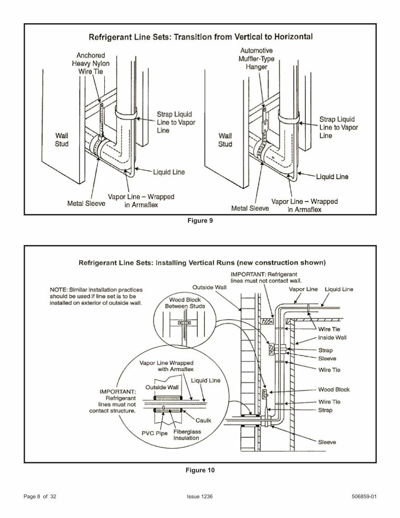
Line Set IsolationIllustrations on pages 7 and 8 demonstrate procedures which ensure proper refrigerant line set isolation. Figure 8 shows how to install line sets on horizontal runs. Figure 9 shows how to make a transition from horizontal to vertical. Figure 10 shows how to install line sets on vertical runs.
Outside Unit Placement and Installation
Table 2
Refrigerant Line Set Diameters (in.)
For installations exceeding 50’, contactTechnical Services
Liquid Line
Btuh Line Set Length and Size12 ft. 25 ft. 50 ft. 75 ft. 100 ft.
24,000 3/8 3/8 3/8 3/8 3/836,000 3/8 3/8 3/8 3/8 1/248,000 3/8 3/8 3/8 1/2 1/260,000 3/8 3/8 3/8 1/2 1/2
Suction Line
Btuh Line Set Length and Size12 ft. 25 ft. 50 ft. 75 ft. 100 ft.
24,000 3/4 7/8 7/8 7/8 7/836,000 7/8 7/8 7/8 7/8 1-1/848,000 7/8 7/8 7/8 1-1/8 1-1/860,000 1-1/8 1-1/8 1-1/8 1-1/8 1-1/8
506859-01 Issue 1236 Page 7 of 32
Installing Refrigerant LineDuring the installation of an air conditioning system, it is important to properly isolate the refrigerant line to prevent unnecessary vibration. Line set contact with the structure (wall, ceiling, or floor) may cause objectionable noise when vibration is translated into sound. As a result, more energy or vibration can be expected. Close attention to line set isolation must be observed.
If this unit is being matched with an approved line set or indoor coil which was previously charged with R-22 refrigerant, the line set and coil must be flushed prior to installation. If the unit is being used with an existing indoor coil which was equipped with a liquid line which served as a metering device (RFCI), the liquid line must be replaced prior to the installation of the 4SCU16/18LS unit.
Field refrigerant piping consists of liquid and suction lines from the outdoor unit (sweat connections) to the indoor coil (flare or sweat connections).
Select line set diameters from Table 2 to ensure that oil returns to the compressor. Size vertical suction riser to maintain minimum velocity at minimum capacity. Recommended line length is 50’ or less. If more than 50’ line set is required, contact Technical Services. Table 2 shows the diameters for line sets up to 100’ although vertical lift applications and trapping requirements need to be reviewed with Technical Services for line sets over 50’.
Figure 8
When flushing existing line set and/or indoor coil, be sure to empty all existing traps. Residual mineral oil can act as an insulator, preventing proper heat transfer. It can also clog the thermal expansion valve, reducing system performance and capacity. Failure to properly flush system as explained in these instructions will void warranty.
CAUTION
To hang line set from joist or rafter,use either metal strapping materialor anchored heavy nylon wire ties.
Strapping Material(around vapor line only)
8’
8’
Tape or Wire Tie
Strap the vapor line to the joist or rafterat 8 intervals then strap the liquid lineto the vapor line.
’
Floor Joist orRoof Rafter
Metal Sleeve
Floor Joist or Roof Rafter
Tape or Wire Tie
Wire Tie(around vapor line only)
Refrigerant Line Sets : Installing Horizontal Runs
506859-01Issue 1236Page 8 of 32
Figure 9
Figure 10
506859-01 Issue 1236 Page 9 of 32
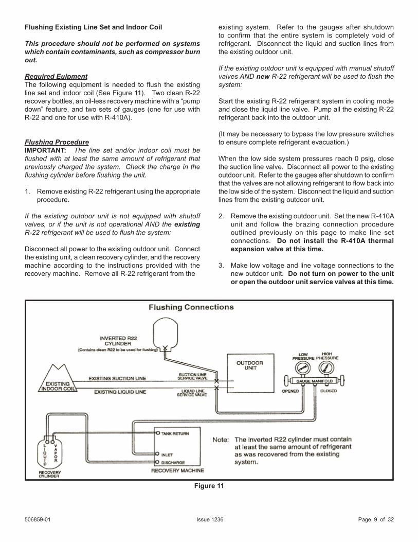
Flushing Existing Line Set and Indoor Coil
This procedure should not be performed on systems which contain contaminants, such as compressor burn out.
Required EuipmentThe following equipment is needed to flush the existing line set and indoor coil (See Figure 11). Two clean R-22 recovery bottles, an oil-less recovery machine with a “pump down” feature, and two sets of gauges (one for use with R-22 and one for use with R-410A).
Flushing ProcedureIMPORTANT: The line set and/or indoor coil must be flushed with at least the same amount of refrigerant that previously charged the system. Check the charge in the flushing cylinder before flushing the unit.
1. Remove existing R-22 refrigerant using the appropriate procedure.
If the existing outdoor unit is not equipped with shutoff valves, or if the unit is not operational AND the existing R-22 refrigerant will be used to flush the system:
Disconnect all power to the existing outdoor unit. Connect the existing unit, a clean recovery cylinder, and the recovery machine according to the instructions provided with the recovery machine. Remove all R-22 refrigerant from the
existing system. Refer to the gauges after shutdown to confirm that the entire system is completely void of refrigerant. Disconnect the liquid and suction lines from the existing outdoor unit.
If the existing outdoor unit is equipped with manual shutoff valves AND new R-22 refrigerant will be used to flush the system:
Start the existing R-22 refrigerant system in cooling mode and close the liquid line valve. Pump all the existing R-22 refrigerant back into the outdoor unit.
(It may be necessary to bypass the low pressure switches to ensure complete refrigerant evacuation.)
When the low side system pressures reach 0 psig, close the suction line valve. Disconnect all power to the existing outdoor unit. Refer to the gauges after shutdown to confirm that the valves are not allowing refrigerant to flow back into the low side of the system. Disconnect the liquid and suction lines from the existing outdoor unit.
2. Remove the existing outdoor unit. Set the new R-410A unit and follow the brazing connection procedure outlined previously on this page to make line set connections. Do not install the R-410A thermal expansion valve at this time.
3. Make low voltage and line voltage connections to the new outdoor unit. Do not turn on power to the unit or open the outdoor unit service valves at this time.
Figure 11
506859-01Issue 1236Page 10 of 32
4. Remove the existing R-22 refrigerant flow control orifice or thermal expansion valve before continuing with flushing procedures. R-22 flow control devices are not approved for use with R-410A refrigerant and may prevent proper flushing. Use a field-provided fitting to reconnect the lines.
5. Remove the pressure tap valve cores from the 4SCU16/18LS units service valves. Connect an R-22 cylinder with clean refrigerant to the suction service valve. Connect the R-22 gauge set to the liquid line valve and connect a recovery maching with an empty recovery tank to the gauge set.
6. Set the recovery machine for liquid recovery and start the recovery machine. Open the gauge set valves to allow the recovery machine to pull a vacuum on the existing system line set and indoor coil.
7. Invert the cylinder of clean R-22 and open its valve to allow liquid refrigerant to flow in to the system through the suction line valve. Allow the refrigerant to pass from the cylinder and through the line set and the indoor coil before it enters the recovery machine.
8. After all of the liquid refrigerant has been recovered, switch the recovery machine to vapor recovery so that all of the R-22 vapor is recovered. Allow the recovery machine to pull a vacuum on the sytem.
NOTE: A single system flush should remove all of the mineral oil from the existing refrigerant lines and indoor coil. A second flushing may be done (using clean refrigerant) if insufficient amounts of mineral oil were removed during the first flush. After each system flush, allow the recovery machine to pull a vacuum on the system at the end of the procedure.
9. Close the valve on the inverted R-22 cylinder and the gauge set valves. Pump the remaining refrigerant out of the recovery machine and turn the machine off.
10. Use nitrogen to break the vacuum on the refrigerant lines and indoor coil before removing the recovery machine, gauges, and R-22 refrigerant drum. Re-install pressure tap valve cores into the 4SCU16/18LS unit’s service valves.
11. Install the fixed orifice (or thermal expansion valve approved for use with R-410A refrigerant) in the liquid line at the indoor coil.
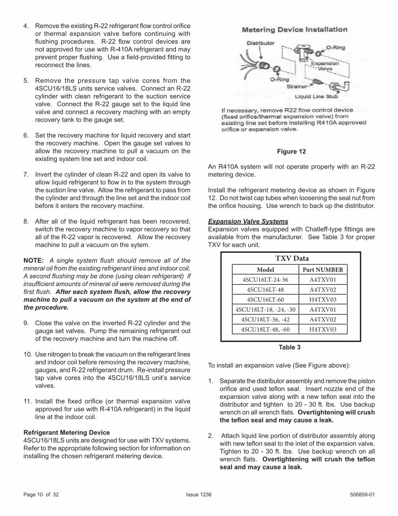
Refrigerant Metering Device4SCU16/18LS units are designed for use with TXV systems. Refer to the appropriate following section for information on installing the chosen refrigerant metering device.
An R410A system will not operate properly with an R-22 metering device.
Install the refrigerant metering device as shown in Figure 12. Do not twist cap tubes when loosening the seal nut from the orifice housing. Use wrench to back up the distributor.
Expansion Valve SystemsExpansion valves equipped with Chatleff-type fittings are available from the manufacturer. See Table 3 for proper TXV for each unit.
To install an expansion valve (See Figure above):
1. Separate the distributor assembly and remove the piston orifice and used teflon seal. Insert nozzle end of the expansion valve along with a new teflon seal into the distributor and tighten to 20 - 30 ft. lbs. Use backup wrench on all wrench flats. Overtightening will crush the teflon seal and may cause a leak.
2. Attach liquid line portion of distributor assembly along with new teflon seal to the inlet of the expansion valve. Tighten to 20 - 30 ft. lbs. Use backup wrench on all wrench flats. Overtightening will crush the teflon seal and may cause a leak.
Figure 12
Table 3
Model Part NUMBER4SCU16LT-24-36 A4TXV01
4SCU16LT-48 A4TXV024SCU16LT-60 H4TXV03
4SCU18LT-18, -24, -30 A4TXV014SCU18LT-36, -42 A4TXV024SCU18LT-48, -60 H4TXV03
TXV Data
506859-01 Issue 1236 Page 11 of 32
3. An R410A system will not operate properly with an R-22 metering device.
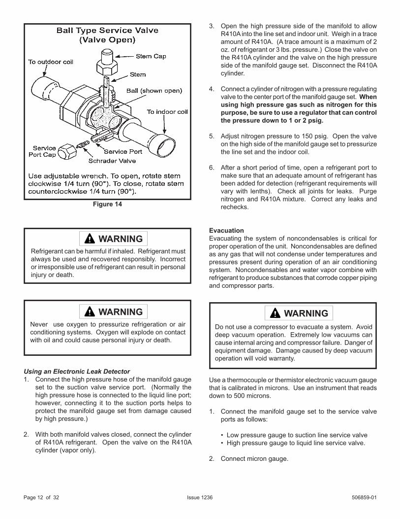
Suction Line (Ball Type) Service ValveSuction line (ball type) service valves function the same way as the other valves; the difference is in the construction (See Figure 14).
The ball valve is equipped with a service port with a factory-installed Schrader valve. A service port cap protects the Schrader valve from contamination and serves as the primary seal.
Leak TestingAfter the line set has been connected to the indoor and outdoor units, the line set connections and indoor unit must be checked for leaks.
Figure 13
3. Connect the external equalizer line to the equalizer port on the suction line and tighten to 8 ft.lbs.
4. Strap the superheat sensing bulb to the suction header.
If installing an expansion valve on an indoor coil that previously used a fixed orifice, be sure to remove the existing fixed orifice. Failure to remove a fixed orifice when installing an expansion valve to the indoor coil will result in improper operation and damage to the system.
Manifold Gauge SetManifold guage sets used with systems charged with R410A refrigerant must be capable of handling the higher system operating pressures. The gauges should be rated for use with pressures 1 - 800 on the high side and a low side of 30” vacuum to 250 psi with dampened speed to 500 psi. Gauge hoses must be rated for use at up to 800 psi of pressure with a 4000 psi burst rating.
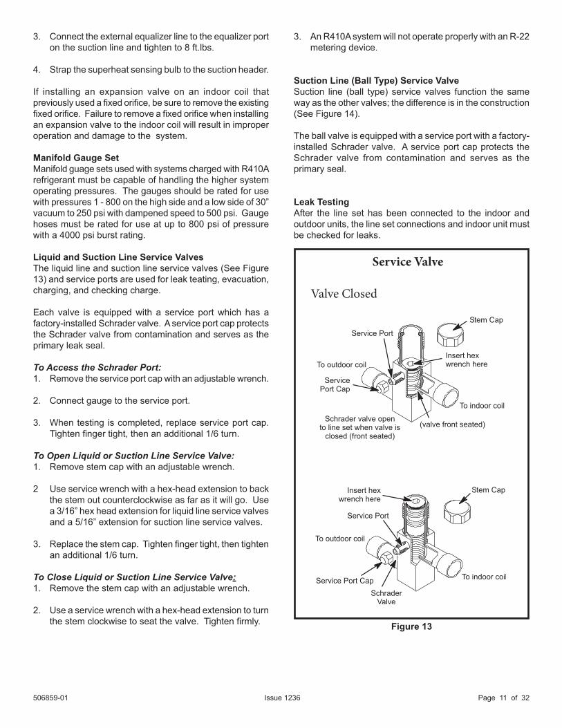
Liquid and Suction Line Service ValvesThe liquid line and suction line service valves (See Figure 13) and service ports are used for leak teating, evacuation, charging, and checking charge.
Each valve is equipped with a service port which has a factory-installed Schrader valve. A service port cap protects the Schrader valve from contamination and serves as the primary leak seal.
To Access the Schrader Port:1. Remove the service port cap with an adjustable wrench.
2. Connect gauge to the service port.
3. When testing is completed, replace service port cap. Tighten finger tight, then an additional 1/6 turn.
To Open Liquid or Suction Line Service Valve:1. Remove stem cap with an adjustable wrench.
2 Use service wrench with a hex-head extension to back the stem out counterclockwise as far as it will go. Use a 3/16” hex head extension for liquid line service valves and a 5/16” extension for suction line service valves.
3. Replace the stem cap. Tighten finger tight, then tighten an additional 1/6 turn.
To Close Liquid or Suction Line Service Valve:1. Remove the stem cap with an adjustable wrench.
2. Use a service wrench with a hex-head extension to turn the stem clockwise to seat the valve. Tighten firmly.
Service Valve
Valve Closed
506859-01Issue 1236Page 12 of 32
Using an Electronic Leak Detector1. Connect the high pressure hose of the manifold gauge
set to the suction valve service port. (Normally the high pressure hose is connected to the liquid line port; however, connecting it to the suction ports helps to protect the manifold gauge set from damage caused by high pressure.)
2. With both manifold valves closed, connect the cylinder of R410A refrigerant. Open the valve on the R410A cylinder (vapor only).
3. Open the high pressure side of the manifold to allow R410A into the line set and indoor unit. Weigh in a trace amount of R410A. (A trace amount is a maximum of 2 oz. of refrigerant or 3 lbs. pressure.) Close the valve on the R410A cylinder and the valve on the high pressure side of the manifold gauge set. Disconnect the R410A cylinder.
4. Connect a cylinder of nitrogen with a pressure regulating valve to the center port of the manifold gauge set. When using high pressure gas such as nitrogen for this purpose, be sure to use a regulator that can control the pressure down to 1 or 2 psig.
5. Adjust nitrogen pressure to 150 psig. Open the valve on the high side of the manifold gauge set to pressurize the line set and the indoor coil.
6. After a short period of time, open a refrigerant port to make sure that an adequate amount of refrigerant has been added for detection (refrigerant requirements will vary with lenths). Check all joints for leaks. Purge nitrogen and R410A mixture. Correct any leaks and rechecks.
EvacuationEvacuating the system of noncondensables is critical for proper operation of the unit. Noncondensables are defined as any gas that will not condense under temperatures and pressures present during operation of an air conditioning system. Noncondensables and water vapor combine with refrigerant to produce substances that corrode copper piping and compressor parts.
Use a thermocouple or thermistor electronic vacuum gauge that is calibrated in microns. Use an instrument that reads down to 500 microns.
1. Connect the manifold gauge set to the service valve ports as follows:
• Low pressure gauge to suction line service valve• High pressure gauge to liquid line service valve.
2. Connect micron gauge.
Do not use a compressor to evacuate a system. Avoid deep vacuum operation. Extremely low vacuums can cause internal arcing and compressor failure. Danger of equipment damage. Damage caused by deep vacuum operation will void warranty.
WARNING
Refrigerant can be harmful if inhaled. Refrigerant must always be used and recovered responsibly. Incorrect or irresponsible use of refrigerant can result in personal injury or death.
WARNING
Never use oxygen to pressurize refrigeration or air conditioning systems. Oxygen will explode on contact with oil and could cause personal injury or death.
WARNING
Figure 14
506859-01 Issue 1236 Page 13 of 32
3. Connect the vacuum pump (with vacuum gauge) to the center port of the manifold gauge set.
4. Open both manifold valves and start vacuum pump.
5. Evacuate the line set and indoor unit to a minimum of 500 microns or lower. During the early stages of evacuation, it is desirable to close the manifold gauge valve at least once to determine if there is a rapid rise in pressure. A rapid rise in pressure indicates a relatively large leak. If this occurs, the leak testing procedure must be repeated.
6. When 500 microns or lower is maintained, close the manifold gauge valves, turn off the vacuum pump, and disconnect the manifold gauge center port hose from the vacuum pump. Attach the manifold gauge center port hose to a nitrogen cylinder with pressure regulator set to 150 psig and purge the hose. Open the manifold gauge valves to break the vacuum in the line set and indoor unit. Close the manifold gauge valves.
7. Shut off the nitrogen cylinder and remove the manifold gauge hose from the cylinder. Open the manifold gauge valves to release the nitrogen from the line set and indoor unit.
8. Reconnect the manifold gauge to the vacuum pump, turn the pump on, and continue to evacuate the line set and indoor unit until 500 microns is maintained within a 20 minute period after shutting off the vacuum pump and closing the manifold gauge valves.
9. When the requirements above have been met, disconnect the manifold hose from the vacuum pump. Open the service valves to break the vacuum in the line set and indoor unit.

506859-01Issue 1236Page 14 of 32
START-UP
1. Rotate fan to check for frozen bearings or binding.
2. Inspect all factory and field-installed wiring for loose connections.
3. After evacuation is complete, open liquid line and suction line service valves to release refrigerant charge (contained in outdoor unit) into system.
4. Replace the stem caps and secure finger tight, then tighten an additional 1/6 of a turn.
5. Check voltage supply at the disconnect switch. The voltage must be within the range listed on the unit nameplate. If not, do not start equipment until the power company has been consulted and the voltage condition corrected.
6. Set thermostat for cooling demand, turn on power to indoor blower, and close the outdoor unit disconnect switch to start the unit.
7. Recheck unit voltage with unit running. Power must be within range shown on unit nameplate.
Refrigerant ChargingThis system is charged with R-410A refrigerant which operates at much higher pressures than R-22. The liquid line drier provided with the unit is approved for use with R-410A. Do not replace it with one designed for use with R-22. This unit is NOT approved for use with coils which use capillary tubes as a refrigerant metering device.
R410A refrigerant cylinders are rose colored. Refrigerant should be added through the suction valve in the liquid state.
Certain R-410A cylinders are identified as being equipped with a dip tube. These allow liquid refrigerant to be drawn from the bottom of the cylinder without inverting the cylinder. Do not turn this type of cylinder upside down to draw refrigerant.
If the system is void of refrigerant, clean the system using the procedure described below.
1. Use dry nitrogen to pressurize the system and check for leaks. Repair leaks, if possible.
2. Evacuate the system to remove as much of the moisture as possible.
3. Use dry nitrogen to break the vacuum.
4. Evacuate the system again.
5. Weigh the appropriate amount of R-410A refrigerant (listed on unit nameplate) into the system.
6. Monitor the system to determine the amount of moisture remaining in the oil. Use a test kit to verify that the moisture content is within the kit’s dry color range. It may be necessary to replace the filter drier several times to achieve the required dryness level. If system dryness is not verified, the compressor will fail in the future.
The outdoor unit should be charged during warm weather. However, applications arise in which charging must occur in the colder months. The method of charging is determined by the unit’s refrigerant metering device and the outdoor ambient temperature.
Table 4
If unit is equipped with a crankcase heater, it should be energized 24 hours before unit start-up to prevent compressor damage as a result of slugging.
CAUTION
Mineral oils are not compatible with R-410A. If oil must be added, it must be a polyolester oil.
IMPORTANT
Units are factory charged with the amount of R410A refrigerant indicated on the unit rating plate. This charge is based on a matching indoor coil and outdoor coil with 15’ line set. For varying lengths of line set, refer to Table 4 for refrigerant charge adjustment. A blank space is provided on the unit rating plate to list the actual field charge.
Refrigerant Charge Adjustment
* If line length is greater than 15 ft. , add this amount. If line length is less than 15 ft., remove this amount.
Liquid Line Set Diameter Oz. Per 5 ft. adjust from 15 ft. line set*
3/8 in. 3 oz. per 5 ft.
506859-01 Issue 1236 Page 15 of 32
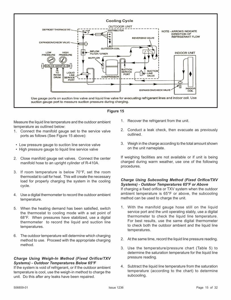
Measure the liquid line temperature and the outdoor ambient temperature as outlined below:1. Connect the manifold gauge set to the service valve
ports as follows (See Figure 15 above):
• Low pressure gauge to suction line service valve • High pressure gauge to liquid line service valve
2. Close manifold gauge set valves. Connect the center manifold hose to an upright cylinder of R-410A.
3. If room temperature is below 70°F, set the room thermostat to call for heat. This will create the necessary load for properly charging the system in the cooling cycle.
4. Use a digital thermometer to record the outdoor ambient temperature.
5. When the heating demand has been satisfied, switch the thermostat to cooling mode with a set point of 68°F. When pressures have stabilized, use a digital thermometer to record the liquid and suction line temperatures.
6. The outdoor temperature will determine which charging method to use. Proceed with the appropriate charging method.
Charge Using Weigh-In Method (Fixed Orifice/TXV Systems) - Outdoor Temperatures Below 65°FIf the system is void of refrigerant, or if the outdoor ambient temperature is cool, use the weigh-in method to charge the unit. Do this after any leaks have been repaired.
1. Recover the refrigerant from the unit.
2. Conduct a leak check, then evacuate as previously outlined.
3. Weigh in the charge according to the total amount shown on the unit nameplate.
If weighing facilities are not available or if unit is being charged during warm weather, use one of the following procedures.
Charge Using Subcooling Method (Fixed Orifice/TXV Systems) - Outdoor Temperatures 65°F or AboveIf charging a fixed orifice or TXV system when the outdoor ambient temperature is 65°F or above, the subcooling method can be used to charge the unit.
1. With the manifold gauge hose still on the liquid service port and the unit operating stably, use a digital thermometer to check the liquid line temperature. For best results, use the same digital thermometer to check both the outdoor ambient and the liquid line temperatures.
2. At the same time, record the liquid line pressure reading.
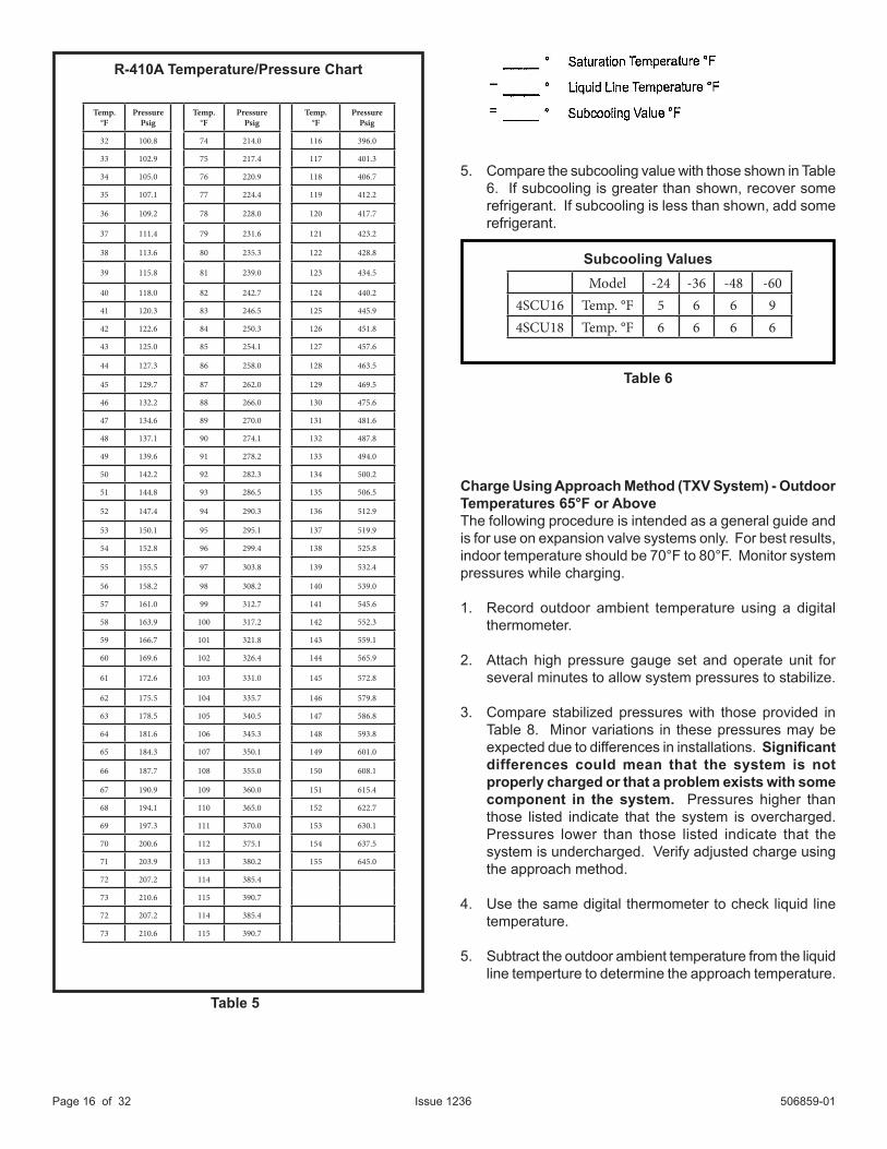
3. Use the temperature/pressure chart (Table 5) to determine the saturation temperature for the liquid line pressure reading.
4. Subtract the liquid line temperature from the saturation temperature (according to the chart) to determine subcooling.
Figure 15
506859-01Issue 1236Page 16 of 32
Table 5
5. Compare the subcooling value with those shown in Table 6. If subcooling is greater than shown, recover some refrigerant. If subcooling is less than shown, add some refrigerant.
Charge Using Approach Method (TXV System) - Outdoor Temperatures 65°F or AboveThe following procedure is intended as a general guide and is for use on expansion valve systems only. For best results, indoor temperature should be 70°F to 80°F. Monitor system pressures while charging.
1. Record outdoor ambient temperature using a digital thermometer.
2. Attach high pressure gauge set and operate unit for several minutes to allow system pressures to stabilize.
3. Compare stabilized pressures with those provided in Table 8. Minor variations in these pressures may be expected due to differences in installations. Significant differences could mean that the system is not properly charged or that a problem exists with some component in the system. Pressures higher than those listed indicate that the system is overcharged. Pressures lower than those listed indicate that the system is undercharged. Verify adjusted charge using the approach method.
4. Use the same digital thermometer to check liquid line temperature.
5. Subtract the outdoor ambient temperature from the liquid line temperture to determine the approach temperature.
R-410A Temperature/Pressure Chart
Table 6
Subcooling Values
Temp.°F
PressurePsig
Temp.°F
Pressure Psig
Temp.°F
Pressure Psig
32 100.8 74 214.0 116 396.0
33 102.9 75 217.4 117 401.3
34 105.0 76 220.9 118 406.7
35 107.1 77 224.4 119 412.2
36 109.2 78 228.0 120 417.7
37 111.4 79 231.6 121 423.2
38 113.6 80 235.3 122 428.8
39 115.8 81 239.0 123 434.5
40 118.0 82 242.7 124 440.2
41 120.3 83 246.5 125 445.9
42 122.6 84 250.3 126 451.8
43 125.0 85 254.1 127 457.6
44 127.3 86 258.0 128 463.5
45 129.7 87 262.0 129 469.5
46 132.2 88 266.0 130 475.6
47 134.6 89 270.0 131 481.6
48 137.1 90 274.1 132 487.8
49 139.6 91 278.2 133 494.0
50 142.2 92 282.3 134 500.2
51 144.8 93 286.5 135 506.5
52 147.4 94 290.3 136 512.9
53 150.1 95 295.1 137 519.9
54 152.8 96 299.4 138 525.8
55 155.5 97 303.8 139 532.4
56 158.2 98 308.2 140 539.0
57 161.0 99 312.7 141 545.6
58 163.9 100 317.2 142 552.3
59 166.7 101 321.8 143 559.1
60 169.6 102 326.4 144 565.9
61 172.6 103 331.0 145 572.8
62 175.5 104 335.7 146 579.8
63 178.5 105 340.5 147 586.8
64 181.6 106 345.3 148 593.8
65 184.3 107 350.1 149 601.0
66 187.7 108 355.0 150 608.1
67 190.9 109 360.0 151 615.4
68 194.1 110 365.0 152 622.7
69 197.3 111 370.0 153 630.1
70 200.6 112 375.1 154 637.5
71 203.9 113 380.2 155 645.0
72 207.2 114 385.4
73 210.6 115 390.7
72 207.2 114 385.4
73 210.6 115 390.7
Model -24 -36 -48 -604SCU16 Temp. °F 5 6 6 94SCU18 Temp. °F 6 6 6 6
506859-01 Issue 1236 Page 17 of 32
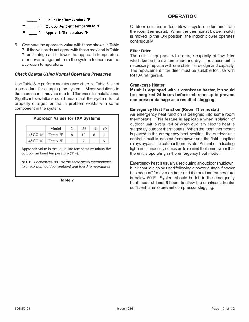
6. Compare the approach value with those shown in Table 7. If the values do not agree with those provided in Table 7, add refrigerant to lower the approach temperature or recover refrigerant from the system to increase the approach temperature.
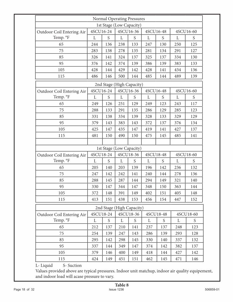
Check Charge Using Normal Operating Pressures
Use Table 8 to perform maintenance checks. Table 8 is not a procedure for charging the system. Minor variations in these pressures may be due to differences in installations. Significant deviations could mean that the system is not properly charged or that a problem exists with some component in the system.
OPERATION
Outdoor unit and indoor blower cycle on demand from the room thermostat. When the thermostat blower switch is moved to the ON position, the indoor blower operates continuously.
Filter DrierThe unit is equipped with a large capacity bi-flow filter which keeps the system clean and dry. If replacement is necessary, replace with one of similar design and capacity. The replacement filter drier must be suitable for use with R410A refrigerant.
Crankcase HeaterIf unit is equipped with a crankcase heater, it should be energized 24 hours before unit start-up to prevent compressor damage as a result of slugging.
Emergency Heat Function (Room Thermostat)An emergency heat function is designed into some room thermostats. This feature is applicable when isolation of outdoor unit is required or when auxiliary electric heat is staged by outdoor thermostats. When the room thermostat is placed in the emergency heat position, the outdoor unit control circuit is isolated from power and the field-supplied relays bypass the outdoor thermostats. An amber indicating light simultaneously comes on to remind the homeowner that the unit is operating in the emergency heat mode.
Emergency heat is usually used during an outdoor shutdown, but it should also be used following a power outage if power has been off for over an hour and the outdoor temperature is below 50°F. System should be left in the emergency heat mode at least 6 hours to allow the crankcase heater sufficient time to prevent compressor slugging.
Approach value is the liquid line temperature minus the outdoor ambient temperature (1°F).
NOTE: For best results, use the same digital thermometer to check both outdoor ambient and liquid temperatures
Table 7
Approach Values for TXV Systems
Model -24 -36 -48 -604SCU 16 Temp. °F 8 10 8 44SCU 18 Temp. °F 1 2 1 5
506859-01Issue 1236Page 18 of 32
Normal Operating Pressures1st Stage (Low Capacity)
Outdoor Coil Entering Air Temp. °F
4SCU16-24 4SCU16-36 4SCU16-48 4SCU16-60L S L S L S L S
65 244 136 238 133 247 130 250 12575 283 138 278 135 281 134 291 12785 326 141 324 137 325 137 334 13095 376 142 374 139 386 139 383 133
105 428 144 429 142 428 141 434 136115 486 146 500 144 485 144 489 139
2nd Stage (High Capacity)Outdoor Coil Entering Air
Temp. °F4SCU16-24 4SCU16-36 4SCU16-48 4SCU16-60
L S L S L S L S65 249 126 251 129 249 123 243 11775 288 133 291 135 286 129 285 12385 331 138 334 139 328 133 329 12995 379 143 383 143 372 137 376 134
105 425 147 435 147 419 141 427 137115 481 150 490 150 475 145 485 141
1st Stage (Low Capacity)Outdoor Coil Entering Air
Temp. °F4SCU18-24 4SCU18-36 4SCU18-48 4SCU18-60
L S L S L S L S65 205 140 203 139 196 142 236 13275 247 142 242 141 240 144 278 13685 288 145 287 144 294 149 321 14095 330 147 344 147 348 150 363 144
105 372 148 391 149 402 151 405 148115 413 151 438 153 456 154 447 152
2nd Stage (High Capacity)Outdoor Coil Entering Air
Temp. °F4SCU18-24 4SCU18-36 4SCU18-48 4SCU18-60
L S L S L S L S65 212 137 210 141 237 137 248 12375 254 139 247 143 286 139 293 12885 295 142 298 145 330 140 337 13295 337 144 349 147 374 142 382 137
105 379 146 400 149 418 144 427 142115 424 149 451 151 462 145 471 146
L- Liquid S- SuctionValues provided above are typical pressures. Indoor unit matchup, indoor air quality equipement,and indoor load will acase pressure to vary.
Table 8
2nd. stage (Low Capacity)
Outdoor Coil Entering Air Temp. °F
4SCU18-24 4SCU18-36 4SCU18-48 4SCU18-60L S L S L S L S
65 212 137 210 141 237 137 248 12375 254 139 247 143 286 139 293 12885 295 142 298 145 330 140 337 13295 337 144 349 147 374 142 382 137
105 379 146 400 149 418 144 427 142115 424 149 451 151 462 145 471 146
506859-01 Issue 1236 Page 19 of 32
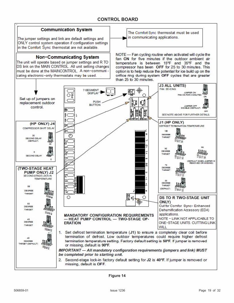
Figure 14
CONTROL BOARD
L- Liquid S- SuctionValues provided above are typical pressures. Indoor unit matchup, indoor air quality equipement,and indoor load will acase pressure to vary.
506859-01Issue 1236Page 20 of 32
Outdoor unit and indoor blower cycle on demand from theroom thermostat. When the thermostat blower switch ismoved to the ON position, the indoor blower operates continuously.
Time DelayThe timed-off delay is 5 minutes long. The delay helps to protect the compressor from short cycling in case the power to the unit is interrupted or a pressure switch opens.
Pressure Switch CircuitThe control includes two pressure switch circuits. A high pressure switch is connected to the board’s HI-PS terminals(See Figure 16). The low pressure, or loss-of-charge pressure switch, is connected to the LO-PS terminals.
During a single demand cycle, the defrost control will lock out the unit after the fifth time that the circuit is interrupted by and pressure switch wired to the control board. In addition, the diagnostic LEDs will indicate a locked-out pressure switch after the fifth occurrence of an open pressure switch.
The unit will remain locked out until power to the board is interrupted, then re-established, or until the error is cleaned.
NOTE: The control board ignores input from the low pressure switch terminals as follows:
• During the TEST mode • During the 90 seconds start-up period
Fan Cycling (J3)Fan cycling routine when activated will cycle the fan ON(see figure 14) for five minutes if the outdoor ambient airtemperature is between 15ºF and 35ºF and the compressorhas been OFF for 25 to 30 minutes. This option is tohelp reduce the potential for ice build up on the orifice ringduring system OFF cycles that are greater than 25 to 30minutes.
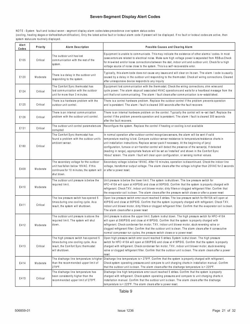
Alert codes are displayed using the seven segment display located on the outdoor control.
NOTE: System fault and lockout alarm code displays takes precedence over system status (cooling, heating stages or defrost/dehumidification).
The seven segment will display an abnormal condition (error code) when detected in the system. A list of the codes are shown in Table 9.
Re-Setting Alert CodesAlert codes can be reset manually or automatically:
Manual ResetManual reset can be achieved by one of the following methods:
• Disconnecting R wire from the main control’s R terminal.
• Turning the indoor unit off and back on again. After power up all existing codes will display 60 seconds and then clear.
Automatic ResetAfter an alert is detected, the main control continues to monitor the unit’s system and compressor operations. When/if conditions return to normal, the alert code is turned off automatically.
Operation Seven-Segment Alert and System Status Codes
506859-01 Issue 1236 Page 21 of 32
Ale rtCode s P riority A la rm De s c ription P os s ib le Ca us e s a nd C le a ring A la rm
E 1 0 5 Cri t i ca lT h e o u td o o r u n i t h a s l o stco m m u n i ca ti o n w i th th e re st o f th esyste m .
E q u i p m e n t i s u n a b l e to co m m u n i ca te . T h i s m a y i n d i ca te th e e x i ste n ce o f o th e r a l a rm s / co d e s. In m o st ca se s e rro rs a re re l a te d to e l e ctri ca l n o i se . M a ke su re h i g h vo l ta g e p o we r i s se p a ra te d fro m RS B u s.Ch e ck fo r m i s-w i re d a n d /o r l o o se co n n e cti o n s b e twe e n th e sta t, i n d o o r u n i t a n d o u td o o r u n i t. Ch e ck fo r a h i g h vo l ta g e so u rce o f n o i se c l o se to th e syste m . T h i s i s a se l f− re co ve ra b l e e rro r.
E 1 2 0 M o d e ra teT h e re i s a d e l a y i n th e o u td o o r u n i tre sp o n d i n g to th e syste m .
T yp i ca l l y , th i s a l a rm /co d e d o e s n o t ca u se a n y i ssu e s a n d w i l l c l e a r o n i ts o wn . T h e a l a rm / co d e i s u su a l l y ca u se d b y a d e l a y i n th e o u td o o r u n i t re sp o n d i n g to th e th e rm o sta t. Ch e ck a l l w i ri n g co n n e cti o n s. C l e a re d a fte r u n re sp o n si ve d e vi ce re sp o n d s to a n y i n q u i ry
E 1 2 4 Cri t i ca lT h e Co m fo rt S yn c th e rm o sta t h a sl o st co m m u n i ca ti o n w i th th e o u td o o ru n i t fo r m o re th a n 3 m i n u te s.
E q u i p m e n t l o st co m m u n i ca ti o n w i th th e th e rm o sta t. Ch e ck th e w i ri n g co n n e cti o n s, o h m w i re s a n dcycl e p o we r. T h e a l a rm sto p s a l l a sso ci a te d HV A C o p e ra ti o n s a n d wa i ts fo r a h e a rtb e a t m e ssa g e fro m th e u n i t th a t’s n o t co m m u n i ca ti n g . T h e a l a rm / fa u l t c l e a rs a fte r co m m u n i ca ti o n i s re−e sta b l i sh e d .
E 1 2 5 Cri t i ca lT h e re i s a h a rd wa re p ro b l e m w i th th eo u td o o r u n i t co n tro l .
T h e re i s a co n tro l h a rd wa re p ro b l e m . Re p l a ce th e o u td o o r co n tro l i f th e p ro b l e m p re ve n ts o p e ra ti o na n d i s p e rsi ste n t. T h e a l a rm / fa u l t i s c l e a re d 3 0 0 se co n d s a fte r th e fa u l t re co ve rs
E 1 2 6 Cri t i ca lT h e re i s a n i n te rn a l co m m u n i ca ti o np ro b l e m w i th th e o u td o o r u n i t co n tro l .
T h e re i s a n i n te rn a l h a rd wa re p ro b l e m o n th e co n tro l . T yp i ca l l y th e co n tro l w i l l re−se t i tse l f. Re p l a ce th eco n tro l i f th e p ro b l e m p re ve n ts o p e ra ti o n a n d i s p e rsi ste n t. T h e a l a rm / fa u l t i s c l e a re d 3 0 0 se co n d sa fte r th e fa u l t re co ve rs.
E 1 3 1 Cri t i ca lT h e o u td o o r u n i t co n tro l p a ra m e te rs a reco rru p te d
Re co n fi g u re th e syste m . Re p l a ce th e co n tro l i f h e a ti n g o r co o l i n g i s n o t a va i l a b l e
E 1 8 0 Cri t i ca l
T h e Co m fo rt S yn c th e rm o sta t h a sfo u n d a p ro b l e m w i th th e o u td o o r u n i t ’sa m b i e n t se n so r.
In n o rm a l o p e ra ti o n a fte r o u td o o r co n tro l re co g n i ze s se n so rs, th e a l a rm w i l l b e se n t i f va l i dte m p e ra tu re re a d i n g i s l o st. Co m p a re o u td o o r se n so r re si sta n ce to te m p e ra tu re /re si sta n ce ch a rts i nu n i t i n sta l l a t i o n i n stru cti o n s. Re p l a ce se n so r p a ck i f n e ce ssa ry. A t th e b e g i n n i n g o f (a n y)co n fi g u ra ti o n , fu rn a ce o r a i r−h a n d l e r co n tro l w i l l d e te ct th e p re se n ce o f th e se n so r(s). I f d e te cte d(re a d i n g i n ra n g e ), a p p ro p ri a te fe a tu re w i l l b e se t a s ’i n sta l l e d ’ a n d sh o wn i n th e Co m fo rt S yn c’A b o u t’ scre e n . T h e a l a rm / fa u l t w i l l c l e a r u p o n co n fi g u ra ti o n , o r se n si n g n o rm a l va l u e s.
E 4 0 9 M o d e ra te
T h e se co n d a ry vo l ta g e fo r th e o u td o o ru n i t h a s fa l l e n b e l o w 1 8 V A C. If th i sco n ti n u e s fo r 1 0 m i n u te s, th e syste m w i l l sh u t d o wn .
S e co n d a ry vo l ta g e i s b e l o w 1 8 V A C. A fte r 1 0 m i n u te s, o p e ra ti o n i s d i sco n ti n u e d . Ch e ck th e i n d o o r l i n evo l ta g e , tra n sfo rm e r o u tp u t vo l ta g e . T h e a l a rm c l e a rs a fte r th e vo l ta g e i s h i g h e r th a n 2 0 V A C fo r 2 se co n d s o r a fte r a p o we r re se t.
E 4 1 0 M o d e ra te
T h e o u td o o r u n i t p re ssu re i s b e l o w th ere q u i re d l i m i t.
Un i t p re ssu re i s b e l o w th e l o we r l i m i t. T h e syste m i s sh u td o wn . T h e l o w p re ssu re sw i tch fo rHFC−4 1 0 A w i l l o p e n a t 4 0 P S IG a n d c l o se a t 9 0 P S IG . Co n fi rm th a t th e syste m i s p ro p e rl y ch a rg e d w i thre fri g e ra n t. Ch e ck T X V , i n d o o r u n i t b l o we r m o to r, d i rty f i l te rs o r c l o g g e d re fri g e ra n t f i l te r. Co n fi rm th a tth e e va p o ra to r co i l i s c l e a n . T h e a l a rm c l e a rs a fte r th e p re ssu re sw i tch c l o se s o r a fte r a p o we r re se t
E 4 1 1 Cri t i ca l
T h e l o w p re ssu re sw i tch h a s o p e n e d 5ti m e s d u ri n g o n e co o l i n g cyc l e . A s are su l t, th e syste m w i l l sh u td o wn .
O p e n l o w p re ssu re sw i tch e rro r co u n t re a ch e d 5 stri ke s. T h e l o w p re ssu re sw i tch fo r R4 1 0 A w i l l o p e n a t 4 0 P S IG a n d c l o se a t 9 0 P S IG . Co n fi rm th a t th e syste m i s p ro p e rl y ch a rg e d w i th re fri g e ra n t. Ch e ck T X V , i n d o o r u n i t b l o we r m o to r, d i rty f i l te rs o r c l o g g e d re fri g e ra n t f i l te r. Co n fi rm th a t th e e va p o ra to r co i l i s c l e a n . T h e a l a rm c l e a rs a fte r a p o we r re se t
E 4 1 2 M o d e ra te
T h e o u td o o r u n i t p re ssu re i s a b o ve th ere q u i re d l i m i t. T h e syste m w i l l sh u t d o wn .
Un i t p re ssu re i s a b o ve th e u p p e r l i m i t. S yste m i s sh u t d o wn . T h e h i g h p re ssu re sw i tch fo r HFC−4 1 0 Awi l l o p e n a t 5 9 0 P S IG a n d c l o se a t 4 1 8 P S IG . Co n fi rm th a t th e syste m i s p ro p e rl y ch a rg e d w i thre fri g e ra n t. Ch e ck co n d e n se r fa n m o to r, T X V , i n d o o r u n i t b l o we r m o to r, stu ck re ve rsi n g va l ve o rc l o g g e d re fri g e ra n t f i l te r. Co n fi rm th a t th e o u td o o r u n i t i s c l e a n . T h e a l a rm c l e a rs a fte r 4 co n se cu ti ven o rm a l co m p re sso r ru n cyc l e s, th e p re ssu re sw i tch c l o se s o r a p o we r re se t
E 4 1 3 Cri t i ca l
T h e h i g h p re ssu re sw i tch h a s o p e n e d 5 t i m e s d u ri n g o n e co o l i n g cyc l e . A s are su l t, th e Co m fo rt S yn c th e rm o sta tw i l l sh u td o wn .
O p e n h i g h p re ssu re sw i tch e rro r co u n t re a ch e d 5 stri ke s. S yste m i s sh u t d o wn . T h e h i g h p re ssu resw i tch fo r HFC−4 1 0 A w i l l o p e n a t 5 9 0 P S IG a n d c l o se a t 4 1 8 P S IG . Co n fi rm th a t th e syste m i s p ro p e rl ych a rg e d w i th re fri g e ra n t. Ch e ck co n d e n se r fa n m o to r, T X V , i n d o o r u n i t b l o we r m o to r, stu ck re ve rsi n gva l ve o r c l o g g e d re fri g e ra n t f i l te r. Co n fi rm th a t th e o u td o o r u n i t i s c l e a n . T h e a l a rm c l e a rs a fte r a p o we rre se t.
E 4 1 4 M o d e ra teT h e d i sch a rg e l i n e te m p e ra tu re i s h i g h e r th a n th e re co m m e n d e d u p p e r l i m i t o f 2 7 9 ºF.
D i sch a rg e l i n e te m p e ra tu re i s > 2 7 9 ºF. Co n fi rm th a t th e syste m i s p ro p e rl y ch a rg e d w i th re fri g e ra n t.Ch e ck syste m o p e ra ti n g p re ssu re s a n d co m p a re to u n i t ch a rg i n g ch a rts i n i n sta l l a t i o n m a n u a l . Co n fi rmth a t th e o u td o o r u n i t i s c l e a n . T h e a l a rm c l e a rs a fte r th e d i sch a rg e te m p e ra tu re i s < 2 2 5 ºF.
E 4 1 5 Cri t i ca l
T h e d i sch a rg e l i n e te m p e ra tu re h a sb e e n co n si ste n tl y h i g h e r th a n th e re co m m e n d e d u p p e r l i m i t o f 2 7 9 ºF.
D i sch a rg e l i n e h i g h te m p e ra tu re e rro r co u n t re a ch e d 5 stri ke s. Co n fi rm th a t th e syste m i s p ro p e rl ych a rg e d w i th re fri g e ra n t. Ch e ck syste m o p e ra ti n g p re ssu re s a n d co m p a re to u n i t ch a rg i n g ch a rts i ni n sta l l a t i o n m a n u a l . Co n fi rm th a t th e o u td o o r u n i t i s c l e a n . T h e a l a rm c l e a rs a fte r th e d i sch a rg e te m p e ra tu re i s < 2 2 5 ºF. T h e a l a rm c l e a rs a fte r a p o we r re se t.
NO T E - S yste m fa u l t a n d l o cko u t se ve n - se g m e n t d i sp l a y a l a rm co d e s ta ke s p re ce d e n ce o ve r syste m sta tu s co d e s(co o l i n g , h e a ti n g sta g e s o r d e fro st/d e h u m i d i f i ca ti o n ). O n l y th e l a te st a cti ve fa u l t o r l o cko u t a l a rm co d e i f p re se n t w i l l b e d i sp l a ye d . If n o fa u l t o r l o cko u t co d e s a re a cti ve , th e n syste m sta tu s a re ro u ti n e l y d i sp l a ye d .
Table 9
Seven-Segment Display Alert Codes
506859-01Issue 1236Page 22 of 32
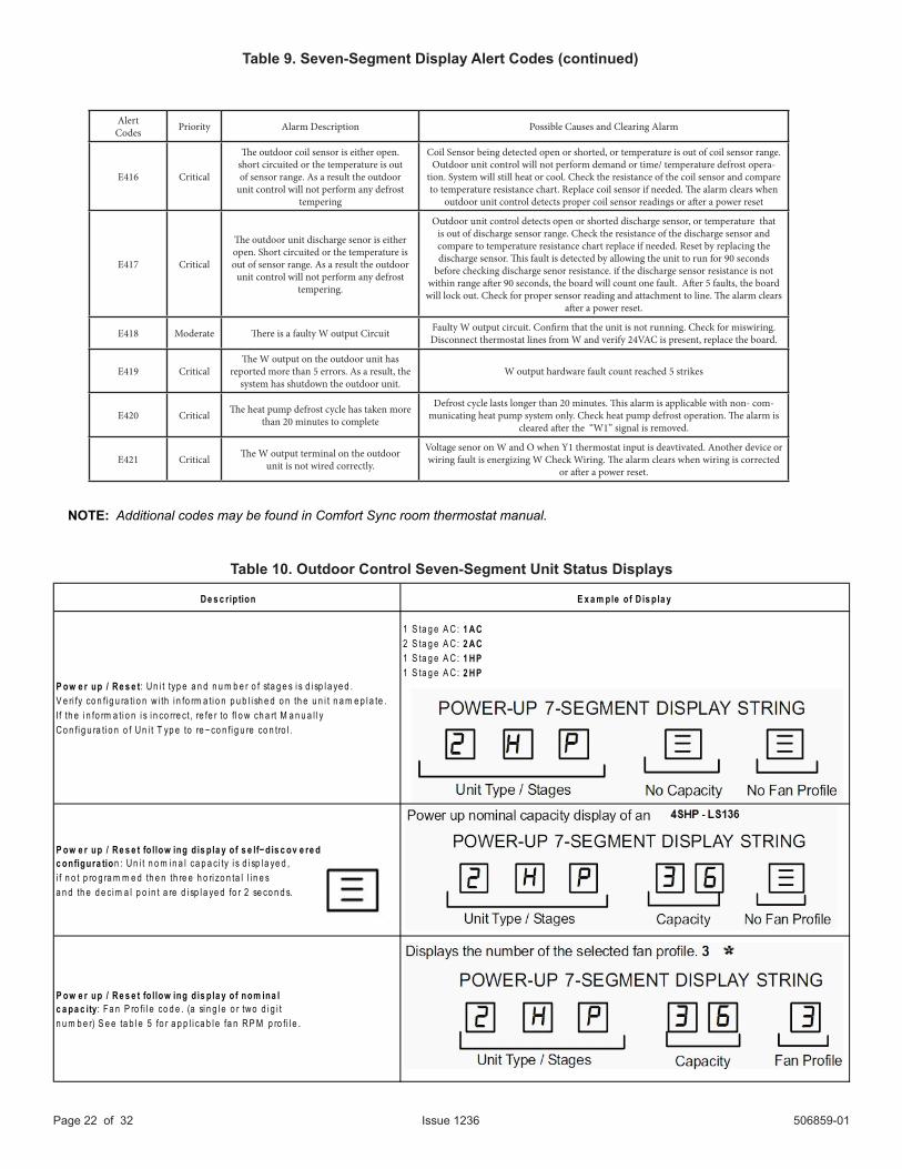
Table 10. Outdoor Control Seven-Segment Unit Status Displays
NOTE: Additional codes may be found in Comfort Sync room thermostat manual.
Table 9. Seven-Segment Display Alert Codes (continued)
De s c ription E x a m ple of D is pla y
1 S ta g e A C: 1 AC2 S ta g e A C: 2 AC1 S ta g e A C: 1 HP1 S ta g e A C: 2 HP
P ow e r up / Re s e t fo llow ing d is pla y of s e lf−dis c ov e re dc onfigura tion : Un i t n o m i n a l ca p a ci ty i s d i sp l a ye d ,i f n o t p ro g ra m m e d th e n th re e h o ri zo n ta l l i n e sa n d th e d e ci m a l p o i n t a re d i sp l a ye d fo r 2 se co n d s.
P ow e r up / Re s e t fo llow ing d is pla y of nom ina lc a pa c ity: Fa n P ro fi l e co d e . (a si n g l e o r two d i g i tn u m b e r) S e e ta b l e 5 fo r a p p l i ca b l e fa n RP M p ro fi l e .
P ow e r up / Re s e t: Un i t typ e a n d n u m b e r o f sta g e s i s d i sp l a ye d .V e ri fy co n fi g u ra ti o n w i th i n fo rm a ti o n p u b l i sh e d o n th e u n i t n a m e p l a te .If th e i n fo rm a ti o n i s i n co rre ct, re fe r to f l o w ch a rt M a n u a l l yCo n fi g u ra ti o n o f Un i t T yp e to re−co n fi g u re co n tro l .
Alert Codes Priority Alarm Description Possible Causes and Clearing Alarm
E416 Critical
The outdoor coil sensor is either open. short circuited or the temperature is out of sensor range. As a result the outdoor
unit control will not perform any defrost tempering
Coil Sensor being detected open or shorted, or temperature is out of coil sensor range. Outdoor unit control will not perform demand or time/ temperature defrost opera-
tion. System will still heat or cool. Check the resistance of the coil sensor and compare to temperature resistance chart. Replace coil sensor if needed. The alarm clears when
outdoor unit control detects proper coil sensor readings or after a power reset
E417 Critical
The outdoor unit discharge senor is either open. Short circuited or the temperature is out of sensor range. As a result the outdoor
unit control will not perform any defrost tempering.
Outdoor unit control detects open or shorted discharge sensor, or temperature that is out of discharge sensor range. Check the resistance of the discharge sensor and compare to temperature resistance chart replace if needed. Reset by replacing the discharge sensor. This fault is detected by allowing the unit to run for 90 seconds
before checking discharge senor resistance. if the discharge sensor resistance is not within range after 90 seconds, the board will count one fault. After 5 faults, the board
will lock out. Check for proper sensor reading and attachment to line. The alarm clears after a power reset.
E418 Moderate There is a faulty W output Circuit Faulty W output circuit. Confirm that the unit is not running. Check for miswiring. Disconnect thermostat lines from W and verify 24VAC is present, replace the board.
E419 CriticalThe W output on the outdoor unit has
reported more than 5 errors. As a result, the system has shutdown the outdoor unit.
W output hardware fault count reached 5 strikes
E420 Critical The heat pump defrost cycle has taken more than 20 minutes to complete
Defrost cycle lasts longer than 20 minutes. This alarm is applicable with non- com-municating heat pump system only. Check heat pump defrost operation. The alarm is
cleared after the “W1” signal is removed.
E421 Critical The W output terminal on the outdoorunit is not wired correctly.
Voltage senor on W and O when Y1 thermostat input is deavtivated. Another device or wiring fault is energizing W Check Wiring. The alarm clears when wiring is corrected
or after a power reset.
506859-01 Issue 1236 Page 23 of 32
* Information will be displayed but does not apply to this unit does
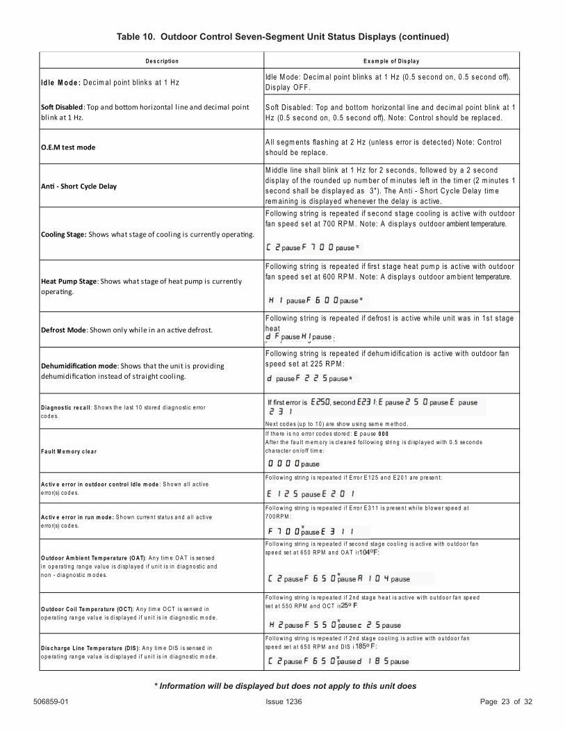
Table 10. Outdoor Control Seven-Segment Unit Status Displays (continued)
De s c ription E x a m ple of D is pla y
Id le M ode : Dec im al point b link s at 1 Hz Idle M ode: Dec im al point b link s at 1 Hz (0.5 s ec ond on, 0.5 s ec ond off). D is play O FF .
Soft Disabled: Top and bottom horizontal l ine and decimal pointblink at 1 Hz.
S oft D is abled: Top and bottom horiz ontal line and dec im al point b link at 1 Hz (0.5 s ec ond on, 0.5 s ec ond off). Note: Control s hould be replac ed.
O.E.M test modeA ll s egm ents flas hing at 2 Hz (unles s error is detec ted) Note: Control s hould be replac e.
Anti - Short Cycle Delay
M iddle line s hall b link at 1 Hz for 2 s ec onds , fo llowed by a 2 s ec ond dis play of the rounded up num ber of m inutes left in the t im er (2 m inutes 1 s ec ond s hall be dis play ed as 3" ). The A nt i - S hort Cy c le Delay t im e rem aining is dis play ed whenever the delay is ac t ive.
Cooling Stage: Shows what stage of cooling is currently operating.
Follow ing s tring is repeated if s ec ond s tage c ooling is ac t ive w ith outdoor fan s peed s et at 700 RP M . Note: A dis play s outdoor ambient temperature.
Heat Pump Stage: Shows what stage of heat pump is currentlyoperating.
Follow ing s tring is repeated if firs t s tage heat pum p is ac t ive w ith outdoor fan s peed s et at 600 RP M . Note: A dis play s outdoor am bient temperature.
Defrost Mode: Shown only while in an active defrost.
Follow ing s tring is repeated if defros t is ac t ive while unit was in 1s t s tage heatpum p heat ing m ode:
Dehumidification mode: Shows that the unit is providing dehumidification instead of straight cooling.
Follow ing s tring is repeated if dehum idific at ion is ac t ive w ith outdoor fans peed s et at 225 RP M :
Dia gnos tic re c a ll : S h o ws th e l a st 1 0 sto re d d i a g n o sti c e rro rco d e s.
Ne xt co d e s (u p to 1 0 ) a re sh o w u si n g sa m e m e th o d .
Fa ult M e m ory c le a r
I f th e re i s n o e rro r co d e s sto re d : E p a u se 0 0 0A fte r th e fa u l t m e m o ry i s c l e a re d fo l l o w i n g stri n g i s d i sp l a ye d w i th 0 .5 se co n d sch a ra cte r o n /o ff t i m e :
Ac tiv e e rror in outdoor c ontro l Id le m ode : S h o wn a l l a cti vee rro r(s) co d e s.
Fo l l o w i n g stri n g i s re p e a te d i f E rro r E 1 2 5 a n d E 2 0 1 a re p re se n t:
Ac tiv e e rror in run m ode : S h o wn cu rre n t sta tu s a n d a l l a cti vee rro r(s) co d e s.
Fo l l o w i n g stri n g i s re p e a te d i f E rro r E 3 1 1 i s p re se n t wh i l e b l o we r sp e e d a t7 0 0 RP M :
O utdoor Am bie nt Te m pe ra ture (O AT): A n y t i m e O A T i s se n se di n o p e ra ti n g ra n g e va l u e i s d i sp l a ye d i f u n i t i s i n d i a g n o sti c a n dn o n - d i a g n o sti c m o d e s.
Fo l l o w i n g stri n g i s re p e a te d i f se co n d sta g e co o l i n g i s a cti ve w i th o u td o o r fa nsp e e d se t a t 6 5 0 RP M a n d O A T i s
O utdoor Coil Te m pe ra ture (O CT): A n y t i m e O CT i s se n se d i no p e ra ti n g ra n g e va l u e i s d i sp l a ye d i f u n i t i s i n d i a g n o sti c m o d e .
Fo l l o w i n g stri n g i s re p e a te d i f 2 n d sta g e h e a t i s a cti ve w i th o u td o o r fa n sp e e dse t a t 5 5 0 RP M a n d O CT i s
Dis c ha rge L ine Te m pe ra ture (D IS ): A n y t i m e D IS i s se n se d i no p e ra ti n g ra n g e va l u e i s d i sp l a ye d i f u n i t i s i n d i a g n o sti c m o d e .
Fo l l o w i n g stri n g i s re p e a te d i f 2 n d sta g e co o l i n g i s a cti ve w i th o u td o o r fa nsp e e d se t a t 6 5 0 RP M a n d D IS i s
506859-01Issue 1236Page 24 of 32
* Information will be displayed but does not apply to this product
506859-01 Issue 1236 Page 25 of 32
506859-01Issue 1236Page 26 of 32
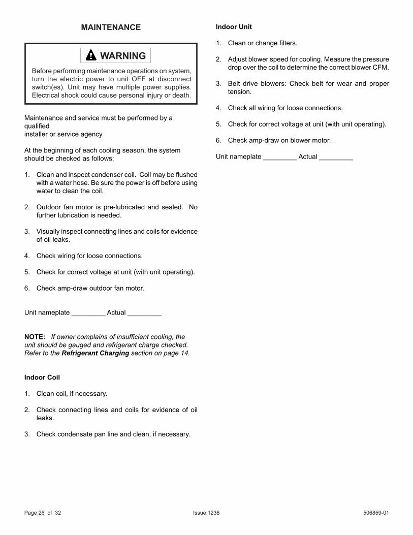
MAINTENANCE
Maintenance and service must be performed by a qualifiedinstaller or service agency.
At the beginning of each cooling season, the systemshould be checked as follows:
1. Clean and inspect condenser coil. Coil may be flushed with a water hose. Be sure the power is off before using water to clean the coil.
2. Outdoor fan motor is pre-lubricated and sealed. No further lubrication is needed.
3. Visually inspect connecting lines and coils for evidence of oil leaks.
4. Check wiring for loose connections.
5. Check for correct voltage at unit (with unit operating).
6. Check amp-draw outdoor fan motor.
Unit nameplate _________ Actual _________
NOTE: If owner complains of insufficient cooling, the unit should be gauged and refrigerant charge checked.Refer to the Refrigerant Charging section on page 14.
Indoor Coil
1. Clean coil, if necessary.
2. Check connecting lines and coils for evidence of oil leaks.
3. Check condensate pan line and clean, if necessary.
Before performing maintenance operations on system, turn the electric power to unit OFF at disconnect switch(es). Unit may have multiple power supplies. Electrical shock could cause personal injury or death.
WARNING
Indoor Unit
1. Clean or change filters.
2. Adjust blower speed for cooling. Measure the pressure drop over the coil to determine the correct blower CFM.
3. Belt drive blowers: Check belt for wear and proper tension.
4. Check all wiring for loose connections.
5. Check for correct voltage at unit (with unit operating).
6. Check amp-draw on blower motor.
Unit nameplate _________ Actual _________
506859-01 Issue 1236 Page 27 of 32
HOMEOWNER INFORMATION
In order to ensure peak performance, your system must be properly maintained. Clogged filters and blocked airflow prevent your unit from operating at its most efficient level.
Ask your dealer to show you where the indoor unit’s filter is located. It will be either at the indoor unit (installed internal or external to the cabinet) or behind a return air grille in the wall or ceiling in your home. Check the filter monthly and clean or replace it as needed.
Disposable filters should be replaced with a filter of the same type and size. If you are unsure of the filter you need for your system, contact your dealer.
Many indoor units are equipped with reusable foam filters. These filters can be cleaned with a mild soap and water solution. Rinse the filter thoroughly and let dry completely before returning to unit or grille.
The filter and all access panels must be in place any time the unit is in operation.
Some systems are equipped with an electronic air cleaner, designed to remove the majority of airborne particles from the air passing through the cleaner. If your system includes an electronic air cleaner, ask your dealer for maintenance instructions.
Inspect and clean indoor coil. The indoor evaporator coil is equipped with a drain pan to collect condensate formed as the system removes humidity from the inside air. Have your dealer show you the location of the drain line and how to check for obstructions. This also applies to an auxiliary drain, if one is installed.
Inspect and clean outdoor coil:Make sure no obstructions restrict airflow to the outdoor unit. Leaves, trash, or shrubs crowding the unit can cause it to work harder and use more energy. Keep shrubbery trimmed away from the unit and periodically check for debris which collects around the unit.
The outdoor coil may require frequent cleaning, depending on environmental conditions. Clean the outdoor coil with an unpressurized water hose to remove surface contaminants and debris. It may be necessary to flush the outdoor coil more frequently if it is exposed to substances which are corrosive or which block airflow across the coil (such as pet urine, cottonwood seeds, etc...).
Turn all electric power to unit OFF at disconnect switch(es) before performing any maintenance operations on system. Unit may have multiple power supplies. Electrical shock could cause personal injury or death.
WARNING
506859-01Issue 1236Page 28 of 32
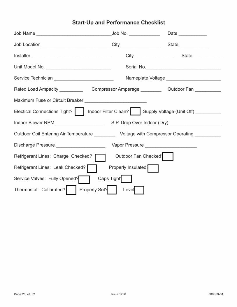
Start-Up and Performance Checklist
Job Name _____________________________ Job No. ____________ Date ___________
Job Location ___________________________ City _______________ State ___________
Installer _______________________________ City _______________ State ___________
Unit Model No. _________________________ Serial No._____________________________
Service Technician _______________________ Nameplate Voltage _____________________
Rated Load Ampacity _________ Compressor Amperage ________ Outdoor Fan __________
Maximum Fuse or Circuit Breaker ________________________
Electical Connections Tight? Indoor Filter Clean? Supply Voltage (Unit Off) __________
Indoor Blower RPM ___________________ S.P. Drop Over Indoor (Dry) ____________________
Outdoor Coil Entering Air Temperature ________ Voltage with Compressor Operating __________
Discharge Pressure ___________________ Vapor Pressure ____________________ Refrigerant Lines: Charge Checked? Outdoor Fan Checked?
Refrigerant Lines: Leak Checked? Properly Insulated?
Service Valves: Fully Opened? Caps Tight?
Thermostat: Calibrated? Properly Set? Level?
506859-01 Issue 1236 Page 29 of 32
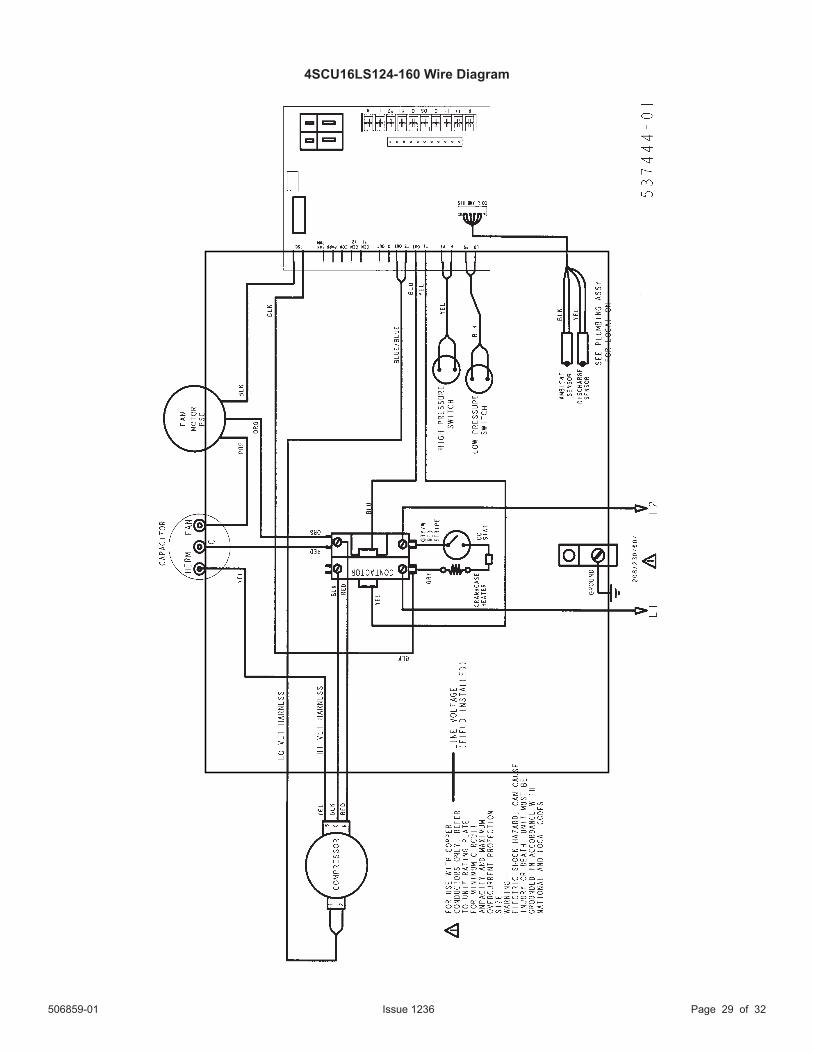
4SCU16LS124-160 Wire Diagram
506859-01Issue 1236Page 30 of 32
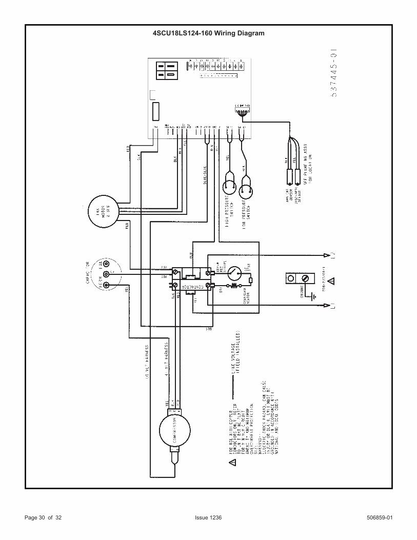
4SCU18LS124-160 Wiring Diagram
506859-01 Issue 1236 Page 31 of 32
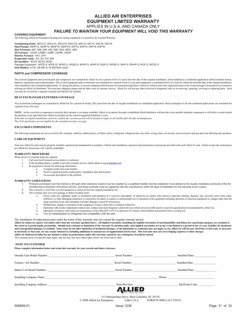
ALLIED AIR ENTERPRISESEQUIPMENT LIMITED WARRANTYAPPLIES IN U.S.A. AND CANADA ONLY
FAILURE TO MAINTAIN YOUR EQUIPMENT WILL VOID THIS WARRANTYCOVERED EQUIPMENTThe following Allied Air Enterprises heating and cooling equipment is covered by the Limited Warranty,
Condensing Units: 4SCU13, 4SCU14, 4SCU16, 4SCU18, 4AC13, 4AC14, 4AC16, 4AC18Heat Pumps: 4SHP13, 4SHP14, 4SHP16, 4SHP18, 4HP13, 4HP14, 4HP16, 4HP18Gas Furnaces: A97, A96, A95, A93, A80, 92G, 95G1, 80GOil Furnace: L83UF, L83BR, L83BF, L83HR, L83HFElectric Furnace: EFC, EFVEvaporator Coils: EC, EU, EH, EMAir handlers: BCS2, BCS3, BCE3Package Equipment: 4PCE13, 4PCE15, 4PGE13, 4PGE15, 4PHP13, 4PHP15, RGE13, RPGE13, RHP13, RPHP13, RCE13, RPCE13Unit Heaters: LF24, (30,000 to 75,000 Btuh units)
PARTS and COMPRESSOR COVERAGE
The covered equipment and covered parts and compressor are warranted by Allied Air for a period of five (5) years from the date of the original installation, when installed in a residential application (which includes homes, duplexes, apartments and condominiums). The covered equipment and covered parts are warranted for a period of one (1) year and compressor is warranted for five (5) years by Allied Air from the date of the original installation, when installed in non-residential applications. If, during this period, a covered component fails because of a manufacturing defect, Allied Air will provide a free replacement part to the owner through a licensed service contractor utilizing an Allied Air distributor. You must pay shipping charges and all other costs of warranty service. Allied Air will not pay labor involved in diagnostic calls or in removing, repairing, servicing or replacing parts. Such cost may be covered by a separate warranty provided by the installer.
HEAT EXCHANGER EXTENDED COVERAGE
All covered heat exchangers are warranted by Allied Air for a period of twenty (20) years from the date of original installation in a residential application. Heat exchangers in all non-residential applications are warranted for a period of ten (10) years.
NOTE: : In the event that a component covered by this warranty is no longer available, Allied, at its option, through a established Allied distributor, will provide a free suitable substitute component or will allow a credit toward the purchase of an equivalent new Allied Air product (at the current suggested distributor’s cost).If the date of original installation cannot be verified, the warranty period will be deemed to begin six (6) months after the date of manufacture.The LF24 unit heaters are not eligible for the extended warranty coverage.
EXCLUDED COMPONENTS
The following components are not covered by this warranty: cabinets, cabinet pieces, air filters, driers, refrigerant, refrigerant line sets, belts, wiring, fuses, oil nozzles, unit accessories and any parts not affecting unit operation.
CARE OF EQUIPMENT
Your new Allied Air unit must be properly installed, operated and maintained in accordance with the unit installation, operation and maintenance instructions provided with each Allied Air unit. Failure to provide maintenance per Allied Air instructions will void this warranty.
WARRANTY PROCEDURE When service or warranty parts are required:
1. Call your local licensed service dealer or contractor2. If the installing dealer is unable to provide warranty service, check online at www.alliedair.com.3. Be prepared to furnish the following information:
a. Complete model and serial numberb. Proof of required periodic maintenance, installation date and location.c. An accurate description of the problem
WARRANTY LIMITATIONS1. Products purchased over the internet or through other electronic means must be installed by a qualified installer and the installation must adhere to the Quality Installation protocols of the Air
Conditioning Contractors of America (ACCA), and these products must be registered with the manufacturer within 60 days of installation for the warranty to be in place.2. This warranty is void if the covered equipment is removed from the original installation site.3. This warranty does not cover damage or defect resulting from:
a. Flood, wind, fire, lightning, mold, or installation and operation in a corrosive atmosphere, or otherwise in contact with corrosive materials (chorine, fluorine, salt, recycled waste water, urine, fertilizers, or other damaging substances or chemicals).Accident, or neglect or unreasonable use or operation of the equipment including operation of electrical equipment at voltages other than the range specified on the unit nameplate (includes damages caused by brownouts).
b. Modification, change or alteration of the equipment, except as directed in writing by Allied Air.c. Operation with system components (indoor unit, outdoor unit and refrigerant control devices) which are not an ARI match or meet the specifications recommended by Allied Air.d. Operation of furnaces with return air temperatures of less than 60ºF (16ºC) or operation of a furnace field installed downstream from a cooling coil.e. Use of contaminated or refrigerant not compatible with the unit.
The installation of replacement parts under the terms of this warranty does not extend the original warranty period.Allied Air makes no express warranties other than the warranty specified above. All implied warranties, including the implied warranties of merchantability and fitness for a particular purpose, are excluded to the extent to a period legally permissible. Should such exclusion or limitation of the warranty be unenforceable, such implied warranties are in any event limited to a period of one (1) year. Liability for incidental and consequential damages is excluded. Some states do not allow limitation of incidental damages, so the limitations or exclusions may not apply to you. Allied Air will not pay electricity or fuel costs, or increases in electricity or fuel costs, for any reason whatsoever, including additional or unusual use of supplemental electric heat. This warranty does not cover lodging expenses or labor charges. Allied Air shall not be liable for any default or delay in performance under this warranty caused by any contingency beyond its control.This warranty gives you specific legal rights, and you may also have other rights which vary from state to state.
NOTE TO CUSTOMERPlease complete information below and retain this warranty for your records and future reference.
Outside Unit Model Number: _______________________________________________ Serial Number: _______________________________ Installed Date: _______________
Furnace / Air Handler: ____________________________________________________ Serial Number: _______________________________ Installed Date: _______________
Indoor Coil Model Number: ________________________________________________ Serial Number: _______________________________ Installed Dare: _______________
Installing Company Name: ________________________________________________________________________________ Phone: _________________________________
Installing Company Address: ________________________________________________ State/Province: _______________________________ Zip/Postal Code: ____________
215 Metropolitan Drive, West Columbia, SC 29170 © 2008 Allied Air Enterprises Litho U.S.A. FORM W-2008-2 (4/17/2013)
506859-01Issue 1236Page 32 of 32
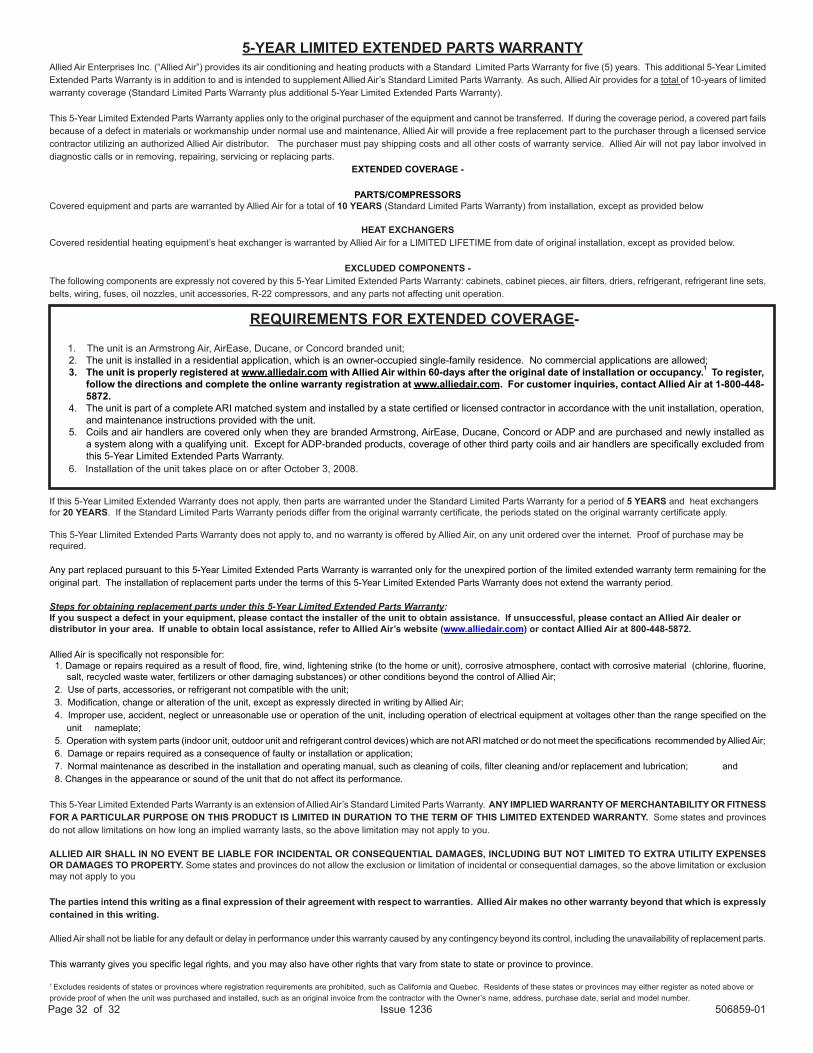
Allied Air Enterprises Inc. (“Allied Air”) provides its air conditioning and heating products with a Standard Limited Parts Warranty for five (5) years. This additional 5-Year Limited Extended Parts Warranty is in addition to and is intended to supplement Allied Air’s Standard Limited Parts Warranty. As such, Allied Air provides for a total of 10-years of limited warranty coverage (Standard Limited Parts Warranty plus additional 5-Year Limited Extended Parts Warranty).
This 5-Year Limited Extended Parts Warranty applies only to the original purchaser of the equipment and cannot be transferred. If during the coverage period, a covered part fails because of a defect in materials or workmanship under normal use and maintenance, Allied Air will provide a free replacement part to the purchaser through a licensed service contractor utilizing an authorized Allied Air distributor. The purchaser must pay shipping costs and all other costs of warranty service. Allied Air will not pay labor involved in diagnostic calls or in removing, repairing, servicing or replacing parts.
EXTENDED COVERAGE -
PARTS/COMPRESSORSCovered equipment and parts are warranted by Allied Air for a total of 10 YEARS (Standard Limited Parts Warranty) from installation, except as provided below
HEAT EXCHANGERSCovered residential heating equipment’s heat exchanger is warranted by Allied Air for a LIMITED LIFETIME from date of original installation, except as provided below.
EXCLUDED COMPONENTS -The following components are expressly not covered by this 5-Year Limited Extended Parts Warranty: cabinets, cabinet pieces, air filters, driers, refrigerant, refrigerant line sets, belts, wiring, fuses, oil nozzles, unit accessories, R-22 compressors, and any parts not affecting unit operation.
If this 5-Year Limited Extended Warranty does not apply, then parts are warranted under the Standard Limited Parts Warranty for a period of 5 YEARS and heat exchangers for 20 YEARS. If the Standard Limited Parts Warranty periods differ from the original warranty certificate, the periods stated on the original warranty certificate apply.
This 5-Year Llimited Extended Parts Warranty does not apply to, and no warranty is offered by Allied Air, on any unit ordered over the internet. Proof of purchase may be required.
Any part replaced pursuant to this 5-Year Limited Extended Parts Warranty is warranted only for the unexpired portion of the limited extended warranty term remaining for the original part. The installation of replacement parts under the terms of this 5-Year Limited Extended Parts Warranty does not extend the warranty period.
Steps for obtaining replacement parts under this 5-Year Limited Extended Parts Warranty:If you suspect a defect in your equipment, please contact the installer of the unit to obtain assistance. If unsuccessful, please contact an Allied Air dealer or distributor in your area. If unable to obtain local assistance, refer to Allied Air’s website (www.alliedair.com) or contact Allied Air at 800-448-5872.
Allied Air is specifically not responsible for:1. Damage or repairs required as a result of flood, fire, wind, lightening strike (to the home or unit), corrosive atmosphere, contact with corrosive material (chlorine, fluorine,
salt, recycled waste water, fertilizers or other damaging substances) or other conditions beyond the control of Allied Air;2. Use of parts, accessories, or refrigerant not compatible with the unit;3. Modification, change or alteration of the unit, except as expressly directed in writing by Allied Air;4. Improper use, accident, neglect or unreasonable use or operation of the unit, including operation of electrical equipment at voltages other than the range specified on the
unit nameplate;5. Operation with system parts (indoor unit, outdoor unit and refrigerant control devices) which are not ARI matched or do not meet the specifications recommended by Allied Air;6. Damage or repairs required as a consequence of faulty or installation or application;7. Normal maintenance as described in the installation and operating manual, such as cleaning of coils, filter cleaning and/or replacement and lubrication; and 8. Changes in the appearance or sound of the unit that do not affect its performance.
This 5-Year Limited Extended Parts Warranty is an extension of Allied Air’s Standard Limited Parts Warranty. ANY IMPLIED WARRANTY OF MERCHANTABILITY OR FITNESS FOR A PARTICULAR PURPOSE ON THIS PRODUCT IS LIMITED IN DURATION TO THE TERM OF THIS LIMITED EXTENDED WARRANTY. Some states and provinces do not allow limitations on how long an implied warranty lasts, so the above limitation may not apply to you.
ALLIED AIR SHALL IN NO EVENT BE LIABLE FOR INCIDENTAL OR CONSEQUENTIAL DAMAGES, INCLUDING BUT NOT LIMITED TO EXTRA UTILITY EXPENSES OR DAMAGES TO PROPERTY. Some states and provinces do not allow the exclusion or limitation of incidental or consequential damages, so the above limitation or exclusion may not apply to you
The parties intend this writing as a final expression of their agreement with respect to warranties. Allied Air makes no other warranty beyond that which is expressly contained in this writing.
Allied Air shall not be liable for any default or delay in performance under this warranty caused by any contingency beyond its control, including the unavailability of replacement parts.
This warranty gives you specific legal rights, and you may also have other rights that vary from state to state or province to province.
1 Excludes residents of states or provinces where registration requirements are prohibited, such as California and Quebec. Residents of these states or provinces may either register as noted above or provide proof of when the unit was purchased and installed, such as an original invoice from the contractor with the Owner’s name, address, purchase date, serial and model number.
5-YEAR LIMITED EXTENDED PARTS WARRANTY
1. The unit is an Armstrong Air, AirEase, Ducane, or Concord branded unit;2. The unit is installed in a residential application, which is an owner-occupied single-family residence. No commercial applications are allowed;3. The unit is properly registered at www.alliedair.com with Allied Air within 60-days after the original date of installation or occupancy.1 To register,
follow the directions and complete the online warranty registration at www.alliedair.com. For customer inquiries, contact Allied Air at 1-800-448-5872.
4. The unit is part of a complete ARI matched system and installed by a state certified or licensed contractor in accordance with the unit installation, operation, and maintenance instructions provided with the unit.
5. Coils and air handlers are covered only when they are branded Armstrong, AirEase, Ducane, Concord or ADP and are purchased and newly installed as a system along with a qualifying unit. Except for ADP-branded products, coverage of other third party coils and air handlers are specifically excluded from this 5-Year Limited Extended Parts Warranty.
6. Installation of the unit takes place on or after October 3, 2008.
REQUIREMENTS FOR EXTENDED COVERAGE-