Embed Size (px)
Citation preview

02/11/2016
© 2016 CCI All rights reserved. Specifications are subject to change.
Revision 1.1 1
DS-SCADR365FEEEH2-V1.1-160211
65° Wideband Tri-Sector Antenna
SCA-DR3-65F-EEE-H2
DATA SHEET
Two foot (0.5 m), six port, tri-sector antenna each sector with uniform
horizontal beamwidths covering the extended band from 1710-2690 MHz
Three individual 65° sectors arranged in a cloverleaf configuration in a single
compact radome
One pair of cross-polarized ports for each sector
Small size and center mount post make it ideal for mounting on utility,
lighting and traffic poles
Sharp elevation beamwidth aides in network planning
Simple single housing blends easily into urban environments
Simplified radio assignments due to all band design
Only one antenna is needed due to extended band operation
Exceeds minimum PIM performance requirements
Overview
CCI’s extended band 65° Tri-Sector Small Cell antenna provides full PCS,
AWS, WCS, 2400 MHz and BRS band coverage. With six high band ports
covering 1710-2690 MHz, this two foot (0.5 m) compact antenna provides
three sector coverage in a single canister radome. The unique design of the
antenna elements provides for extremely uniform horizontal beam widths
over the full operating frequency range insuring consistent coverage area for
all bands of operation. The Tri-Sector Antenna is an ideal choice for
Microcells and Small Cell applications in urban and suburban environments
where antenna size and count are restricted. The Tri-Sector antenna can also
be externally configured for quasi-omni operation for 360 degree coverage
from a single microcell. The antenna includes a center mount post which is
well suited for mounting to utility, lighting and traffic poles.
CCI antennas are designed and produced to ISO 9001:2008 certification
standards for reliability and quality in our state-of-the-art manufacturing
facilities.
Applications
Microcells and Small Cells in Urban, Suburban and other visually sensitive
environments
Outdoor Distributed Antenna Systems (ODAS), neutral host in venues,
campuses and other outdoor coverage applications
Macro Cell sites in urban environments with restricted visual impact

02/11/2016
© 2016 CCI All rights reserved. Specifications are subject to change.
Revision 1.1 2
DS-SCADR365FEEEH2-V1.1-160211
65° Wideband Tri-Sector Antenna
SCA-DR3-65F-EEE-H2
SPECIFICATIONS
Electrical
Ports 6 × Ports which cover the full range from 1710-2690 MHz
Frequency Range 1850-1990 MHz 1710-1755/2110-2155 MHz 2305-2360 MHz 2500-2690 MHz
Gain 14.0 dBi 13.5 dBi 14.3 dBi 14.4 dBi 14.4 dBi
Azimuth Beamwidth (-3dB) 66° 67° 64° 64° 63°
Elevation Beamwidth (-3dB) 18.2° 19.9° 17.0° 15.3° 14.0°
Electrical Downtilt 2° 2° 2° 2° 2°
First upper sidelobes at peak gain < -18 dB < -18 dB < -18 dB < -18 dB < -18 dB
Front to back ratio @ 180° > 23 dB > 24 dB > 26 dB > 28 dB > 28 dB
Cross-Polar Port-to-Port Isolation > 25 dB > 27 dB > 27 dB > 30 dB > 30 dB
Voltage Standing Wave Ratio(VSWR) < 1.5:1 < 1.5:1 < 1.5:1 < 1.5:1 < 1.5:1
Passive Intermodulation (2×20W)
≤
-150 dBc
≤
-150 dBc
≤
-150 dBc
≤
-150 dBc
≤
-150 dBc
Input Power Continuous Wave (CW) 300 watts 300 watts 300 watts 300 watts 300 watts
Polarization Dual Linear 45° Dual Linear 45° Dual Linear 45° Dual Linear 45° Dual Linear 45°
Input Impedance 50 ohms 50 ohms 50 ohms 50 ohms 50 ohms
Lightning Protection DC Ground DC Ground DC Ground DC Ground DC Ground
Mechanical
Dimensions (L×D) 20.3 × 9.7 in (516 × 246 mm)
Survival Wind Speed > 150 mph (> 241 kph)
Front Wind Load 42 lbs (187 N) @ 100 mph (161 kph)
Equivalent Flat Plate Area 1.6 ft
2
(0.2 m
2
)
Weight * 10.6 lbs (4.8 kg)
Connector (RF) 6 × 7-16 DIN female
Mounting Pole 1 to 2.5 in (25 to 63 mm)
Wall mount Hardware 0.5 in. (13 mm) diameter recommended
* Weight excludes mounting

02/11/2016
© 2016 CCI All rights reserved. Specifications are subject to change.
Revision 1.1 3
DS-SCADR365FEEEH2-V1.1-160211
65° Wideband Tri-Sector Antenna
SCA-DR3-65F-EEE-H2
SPECIFICATIONS
Mechanical
Bottom View
Connector Spacing
02/11/2016
© 2016 CCI All rights reserved. Specifications are subject to change.
Revision 1.1 4
DS-SCADR365FEEEH2-V1.1-160211
65° Wideband Tri-Sector Antenna
SCA-DR3-65F-EEE-H2
SPECIFICATIONS
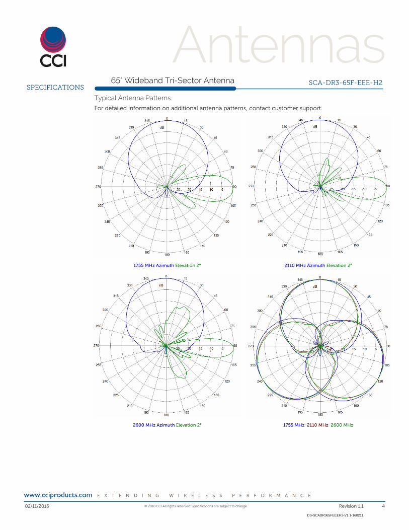
Typical Antenna Patterns
For detailed information on additional antenna patterns, contact customer support.
1755 MHz Azimuth Elevation 2° 2110 MHz Azimuth Elevation 2°
2600 MHz Azimuth Elevation 2° 1755 MHz 2110 MHz 2600 MHz

02/11/2016
© 2016 CCI All rights reserved. Specifications are subject to change.
Revision 1.1 5
DS-SCADR365FEEEH2-V1.1-160211
65° Wideband Tri-Sector Antenna
SCA-DR3-65F-EEE-H2
ORDERING
Parts & Accessories
SCA-DR-65F-EEE-H2 Two foot (0.5 m) antenna, Tri-Sector, Wideband
SCA-DR-65F-EEE-H2-K Two foot (0.5 m) antenna, Trisector, Wideband and
MBC-02 clamp kit(suitable for pole or wall mounting)
MBC-02 Clamp kit, Pipe range 1 - 2.5 in. or lag bolt to wooden
ploe or flat surface(lag bolts not supplied)

02/11/2016
© 2016 CCI All rights reserved. Specifications are subject to change.
Revision 1.1 6
DS-SCADR365FEEEH2-V1.1-160211
Triple Mount Mast Bracket
MBC-02
ACCESSORIES
Mechanical
Dimensions (L x W x D) 7.9×4.3×1.1 in. (200×108×28 mm)
Weight 2.4 lbs (1.1 kg)
Fastener Size 5/16 UNC
Installation Torque (ft-lbs) 10
Bracket Vert. Mount View Bracket Hort. Mount View
Vertical Pole Mount Wooden Pole Mount
Horizontal Pole Mount

02/11/2016
© 2016 CCI All rights reserved. Specifications are subject to change.
Revision 1.1 7
DS-SCADR365FEEEH2-V1.1-160211
65° Wideband Tri-Sector Antenna
SCA-DR3-65F-EEE-H2
STANDARDS &
CERTIFICATIONS
Standards & Compliance
Environmental IEC 60068-2-1, IEC 60068-2-2, IEC 60068-2-5,
IEC 60068-2-6, IEC-60068-2-11, IEC 60068-2-14,
IEC 60068-2-18, IEC 60068-2-27, IEC 60068-2-29,
IEC 60068-02-30, IEC 60068-2-52, IEC 60068-2-64,
GR-63-CORE 4.3.1, EN 606529, IP 24
Certifications
Federal Communication Commission (FCC) Part 15 Class B, CE, CSA US, ISO
9001:2008
![TAPAtion fSLer clinical practice guidanc:t of˜patients … · 2021. 5. 24. · 2005 Muratorietal.[28] ItalianandCaucasian 1and2 B8-DR3-DQ2 – 2006 Teufeletal.[29] German 1 B8-DR3-DQ2](https://img.pdfslide.us/doc/110x75/614633ac8f9ff81254201cd7/tapation-fsler-clinical-practice-guidanct-ofoepatients-2021-5-24-2005-muratorietal28.jpg)

![arXiv:1805.02666v2 [astro-ph.IM] 17 May 2018troscopy, Spitzer/SAGE, Spitzer/IRAC galactic center, UCAC4, UKIDSS/DR10, VST/ATLAS/DR3, VST/KiDS/DR3, WISE and XMM. We provide Python code](https://img.pdfslide.us/doc/110x75/60a1fb95b61d2e1c037c57a2/arxiv180502666v2-astro-phim-17-may-2018-troscopy-spitzersage-spitzerirac.jpg)