Embed Size (px)
Citation preview

TI069D/06/en/06.10
71115124
Technical Information
Proline t-mass 65F, 65I
Thermal Mass Flow Measuring System
Direct Mass Flow Measurement of Gases
Application
For measuring the mass flowrate of a wide range of gas
types e.g.
• Compressed air
• Natural gas flow to boilers/dryers
• Carbon Dioxide flow in breweries
• Biogas and aeration air in waste water plants
• Gas production (e. g. Ar, N2, CO2, He, O2)
• Leakage detection
Approvals for hazardous area:
• ATEX, FM, CSA, IECEx, NEPSI
Connection to all common process control systems:
• HART, PROFIBUS DP/PA, FOUNDATION Fieldbus,
MODBUS RS485
Your benefits
Direct measurement of gas mass flow. Provides
temperature as an output.
The Proline transmitter concept comprises:
• Modular device and operating concept resulting in a
higher degree of efficiency
• Quick setup operating menus for ease of
commissioning
• On board software freely allows the selection of up to
20 pure gases and creation of mixed gases with a
maximum of 8 components (e. g. Biogas)
The t-mass sensors offer:
• Negligible pressure drop or loss
• Wide turndown of up to 100:1
• Insertion version can be programmed for circular pipe
or rectangular ducting installation
• Each device individually calibrated and delivered with
a traceable certificate
• Can be calibrated with flow conditioner on request.
• Optional hot tap device for insertion allowing ease of
removal/replacement for range of process pressure up
to 16 Barg (230 psig) and non-toxic gas applications.
Proline t-mass 65F, 65I
2 Endress+Hauser
Table of contents
Function and system design. . . . . . . . . . . . . . . . . . . . . 3
Measuring principle . . . . . . . . . . . . . . . . . . . . . . . . . . . . . . . . . . . 3
Measuring system . . . . . . . . . . . . . . . . . . . . . . . . . . . . . . . . . . . . . 3
Input . . . . . . . . . . . . . . . . . . . . . . . . . . . . . . . . . . . . . . 4
Measured variable . . . . . . . . . . . . . . . . . . . . . . . . . . . . . . . . . . . . 4
Measuring range (air at ambient conditions) . . . . . . . . . . . . . . . . . 4
Input signal . . . . . . . . . . . . . . . . . . . . . . . . . . . . . . . . . . . . . . . . . 5
Output . . . . . . . . . . . . . . . . . . . . . . . . . . . . . . . . . . . . . 5
Output signal . . . . . . . . . . . . . . . . . . . . . . . . . . . . . . . . . . . . . . . . 5
Signal on alarm . . . . . . . . . . . . . . . . . . . . . . . . . . . . . . . . . . . . . . 7
Load . . . . . . . . . . . . . . . . . . . . . . . . . . . . . . . . . . . . . . . . . . . . . . 7
Low flow cut off . . . . . . . . . . . . . . . . . . . . . . . . . . . . . . . . . . . . . . 7
Galvanic isolation . . . . . . . . . . . . . . . . . . . . . . . . . . . . . . . . . . . . . 7
Switching output . . . . . . . . . . . . . . . . . . . . . . . . . . . . . . . . . . . . . 7
Power supply. . . . . . . . . . . . . . . . . . . . . . . . . . . . . . . . 8
Electrical connection Measuring unit . . . . . . . . . . . . . . . . . . . . . . 8
Terminal assignment . . . . . . . . . . . . . . . . . . . . . . . . . . . . . . . . . . 9
Electrical connection Remote version . . . . . . . . . . . . . . . . . . . . . 10
Supply voltage . . . . . . . . . . . . . . . . . . . . . . . . . . . . . . . . . . . . . . 10
Cable entries . . . . . . . . . . . . . . . . . . . . . . . . . . . . . . . . . . . . . . . 10
Remote version
cable specifications . . . . . . . . . . . . . . . . . . . . . . . . . . . . . . . . . . . 10
Power consumption . . . . . . . . . . . . . . . . . . . . . . . . . . . . . . . . . . 10
Power supply failure . . . . . . . . . . . . . . . . . . . . . . . . . . . . . . . . . . 11
Potential equalization . . . . . . . . . . . . . . . . . . . . . . . . . . . . . . . . . 11
Performance characteristics. . . . . . . . . . . . . . . . . . . . 11
Calibration reference conditions . . . . . . . . . . . . . . . . . . . . . . . . . 11
Maximum measured error . . . . . . . . . . . . . . . . . . . . . . . . . . . . . 11
Repeatability . . . . . . . . . . . . . . . . . . . . . . . . . . . . . . . . . . . . . . . . 11
Influence of medium pressure
(Pressure co-efficient) . . . . . . . . . . . . . . . . . . . . . . . . . . . . . . . . . 11
Response time . . . . . . . . . . . . . . . . . . . . . . . . . . . . . . . . . . . . . . 11
Operating conditions: Installation . . . . . . . . . . . . . . . 12
Installation instructions . . . . . . . . . . . . . . . . . . . . . . . . . . . . . . . . 12
Inlet and outlet runs . . . . . . . . . . . . . . . . . . . . . . . . . . . . . . . . . . 14
Mounting conditions for the insertion version . . . . . . . . . . . . . . . 17
Length of connecting cable . . . . . . . . . . . . . . . . . . . . . . . . . . . . . 18
Operating conditions: Environment. . . . . . . . . . . . . . 18
Ambient temperature . . . . . . . . . . . . . . . . . . . . . . . . . . . . . . . . . 18
Storage temperature . . . . . . . . . . . . . . . . . . . . . . . . . . . . . . . . . . 18
Degree of protection . . . . . . . . . . . . . . . . . . . . . . . . . . . . . . . . . . 18
Shock resistance . . . . . . . . . . . . . . . . . . . . . . . . . . . . . . . . . . . . . 18
Vibration resistance . . . . . . . . . . . . . . . . . . . . . . . . . . . . . . . . . . 18
Electromagnetic compatibility (EMC) . . . . . . . . . . . . . . . . . . . . . 18
Operating conditions: Process . . . . . . . . . . . . . . . . . . 19
Medium temperature range . . . . . . . . . . . . . . . . . . . . . . . . . . . . 19
Pressure loss . . . . . . . . . . . . . . . . . . . . . . . . . . . . . . . . . . . . . . . . 19
Medium pressure range (nominal pressure) . . . . . . . . . . . . . . . . . 19
Flow limit . . . . . . . . . . . . . . . . . . . . . . . . . . . . . . . . . . . . . . . . . 19
Process conditions for Hot tap . . . . . . . . . . . . . . . . . . . . . . . . . . 19
Mechanical construction . . . . . . . . . . . . . . . . . . . . . . 20
Design, dimensions . . . . . . . . . . . . . . . . . . . . . . . . . . . . . . . . . . 20
Weight . . . . . . . . . . . . . . . . . . . . . . . . . . . . . . . . . . . . . . . . . . . 36
Materials . . . . . . . . . . . . . . . . . . . . . . . . . . . . . . . . . . . . . . . . . . 36
Material load curves . . . . . . . . . . . . . . . . . . . . . . . . . . . . . . . . . . 37
Process connections . . . . . . . . . . . . . . . . . . . . . . . . . . . . . . . . . . 38
Human interface . . . . . . . . . . . . . . . . . . . . . . . . . . . . 39
Display elements . . . . . . . . . . . . . . . . . . . . . . . . . . . . . . . . . . . . 39
Operating elements . . . . . . . . . . . . . . . . . . . . . . . . . . . . . . . . . . 39
Languages . . . . . . . . . . . . . . . . . . . . . . . . . . . . . . . . . . . . . . . . . 39
Remote operation . . . . . . . . . . . . . . . . . . . . . . . . . . . . . . . . . . . . 39
Certificates and approvals . . . . . . . . . . . . . . . . . . . . . 39
CE mark . . . . . . . . . . . . . . . . . . . . . . . . . . . . . . . . . . . . . . . . . . 39
C-Tick mark . . . . . . . . . . . . . . . . . . . . . . . . . . . . . . . . . . . . . . . 39
Ex approval . . . . . . . . . . . . . . . . . . . . . . . . . . . . . . . . . . . . . . . . 39
FOUNDATION Fieldbus certification . . . . . . . . . . . . . . . . . . . . 39
PROFIBUS DP/PA certification . . . . . . . . . . . . . . . . . . . . . . . . . 40
MODBUS certification . . . . . . . . . . . . . . . . . . . . . . . . . . . . . . . . 40
Pressure measuring device approval . . . . . . . . . . . . . . . . . . . . . . 40
Oxygen service . . . . . . . . . . . . . . . . . . . . . . . . . . . . . . . . . . . . . 40
Other standards and guidelines . . . . . . . . . . . . . . . . . . . . . . . . . . 40
Ordering information. . . . . . . . . . . . . . . . . . . . . . . . . 41
Accessories . . . . . . . . . . . . . . . . . . . . . . . . . . . . . . . . 41
Device-specific accessories . . . . . . . . . . . . . . . . . . . . . . . . . . . . . 41
Measuring principle-specific accessories . . . . . . . . . . . . . . . . . . . 41
Service-specific accessories . . . . . . . . . . . . . . . . . . . . . . . . . . . . . 42
Communication-specific accessories . . . . . . . . . . . . . . . . . . . . . . 42
Documentation . . . . . . . . . . . . . . . . . . . . . . . . . . . . . 43
Registered trademarks . . . . . . . . . . . . . . . . . . . . . . . . 43
Proline t-mass 65F, 65I
Endress+Hauser 3
Function and system design
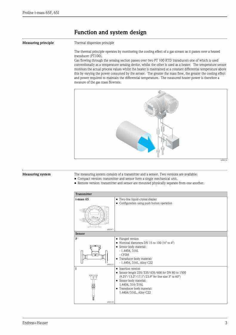
Measuring principle Thermal dispersion principle
The thermal principle operates by monitoring the cooling effect of a gas stream as it passes over a heated
transducer (PT100).
Gas flowing through the sensing section passes over two PT 100 RTD transducers one of which is used
conventionally as a temperature sensing device, whilst the other is used as a heater. The temperature sensor
monitors the actual process values whilst the heater is maintained at a constant differential temperature above
this by varying the power consumed by the sensor. The greater the mass flow, the greater the cooling effect
and power required to maintain the differential temperature. The measured heater power is therefore a
measure of the gas mass flowrate.
a0005136
Measuring system The measuring system consists of a transmitter and a sensor. Two versions are available:
• Compact version: transmitter and sensor form a single mechanical unit.
• Remote version: transmitter and sensor are mounted physically separate from one another.
Transmitter
t-mass 65
a0003671
• Two-line liquid-crystal display
• Configuration using push button operation
Sensor
F
a0005137
• Flanged version
• Nominal diameters DN 15 to 100 (½" to 4")
• Sensor body material:
- 1.4404, 316L
- CF3M
• Transducer body material:
- 1.4404, 316L, Alloy C22
I
a0005138
• Insertion version
• Sensor length 235/335/435/608 for DN 80 to 1500
(9.25"/13.2"/17.1"/23.9" for line size 3" to 60")
• Sensor body material:
1.4404, 316/316L
• Transducer body material:
1.4404/316L, Alloy C22
Esc
E- +
Proline t-mass 65F, 65I
4 Endress+Hauser
Input
Measured variable • Mass flow
• Gas temperature
• Gas heat flow
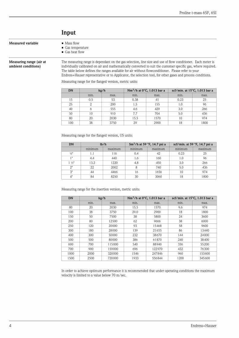
Measuring range (air at
ambient conditions)
The measuring range is dependant on the gas selection, line size and use of flow conditioner. Each meter is
individually calibrated on air and mathematically converted to suit the customer specific gas, where required.
The table below defines the ranges available for air without flowconditioner. Please refer to your
Endress+Hauser representative or to Applicator, the selection tool, for other gases and process conditions.
Measuring range for the flanged version, metric units:
Measuring range for the flanged version, US units:
Measuring range for the insertion version, metric units:
In order to achieve optimum performance it is recommended that under operating conditions the maximum
velocity is limited to a value below 70 m/sec.
DN kg/h Nm3/h at 0°C, 1.013 bar a scf/min. at 15°C, 1.013 bar a
min. max. min. max. min. max.
15 0.5 53 0.38 41 0.23 25
25 2 200 1.5 155 1.0 96
40 6 555 4.6 429 3.0 266
50 10 910 7.7 704 5.0 436
80 20 2030 15.5 1570 10 974
100 38 3750 29 2900 18 1800
DN lb/h Sm3/h at 59 °F, 14.7 psi a scf/min. at 59 °F, 14.7 psi a
minimum maximum minimum maximum minimum maximum
½" 1.1 116 0.4 42 0.23 25
1" 4.4 440 1.6 160 1.0 96
1 ½" 13.2 1220 4.8 450 3.0 266
2" 22 2002 8 740 5.0 436
3" 44 4466 16 1656 10 974
4" 84 8250 30 3060 18 1800
DN kg/h Nm3/h at 0°C, 1.013 bar a scf/min. at 15°C, 1.013 bar a
min. max. min. max. min. max.
80 20 2030 15.5 1570 9.6 974
100 38 3750 29.0 2900 18 1800
150 50 7500 38 5800 24 3600
200 80 12500 62 9666 38 6000
250 120 20000 93 15468 58 9600
300 180 28000 139 21655 86 13440
400 300 50000 232 38670 144 24000
500 500 80000 386 61870 240 38400
600 700 115000 540 88940 336 55200
700 900 159000 696 122970 432 76300
1000 2000 320000 1546 247846 960 153600
1500 2500 720000 1933 556844 1200 345600
Proline t-mass 65F, 65I
Endress+Hauser 5
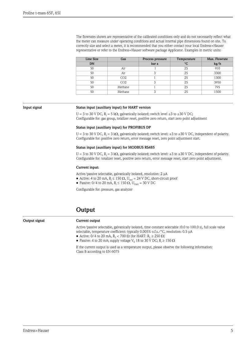
The flowrates shown are representative of the calibrated conditions only and do not necessarily reflect what
the meter can measure under operating conditions and actual internal pipe dimensions found on site. To
correctly size and select a meter, it is recommended that you either contact your local Endress+Hauser
representative or refer to the Endress+Hauser software package Applicator. Examples in metric units:
Input signal Status input (auxiliary input) for HART version
U = 3 to 30 V DC, Ri = 5 kΩ, galvanically isolated; switch level ±3 to ±30 V DC;
Configurable for: gas group, totalizer reset, positive zero return, start zero point adjustment
Status input (auxiliary input) for PROFIBUS DP
U = 3 to 30 V DC, Ri = 3 kΩ, galvanically isolated; switch level: ±3 to ±30 V DC, independent of polarity.
Configurable for: positive zero return, error message reset, zero point adjustment start.
Status input (auxiliary input) for MODBUS RS485
U = 3 to 30 V DC, Ri = 3 kΩ, galvanically isolated; switch level: ±3 to ±30 V DC, independent of polarity.
Configurable for: totalizer reset, positive zero return, error message reset, start zero point adjustment.
Current input:
Active/passive selectable, galvanically isolated, resolution: 2 μA
• Active: 4 to 20 mA, Ri ≤ 150 Ω, Uout = 24 V DC, short-circuit proof
• Passive: 0/4 to 20 mA, Ri ≤ 150 Ω, Umax = 30 V DC
Configurable for: pressure, gas analyzer
Output
Output signal Current output
Active/passive selectable, galvanically isolated, time constant selectable (0.0 to 100.0 s), full scale value
selectable, temperature coefficient: typically 0.005% o.f.s./°C, resolution: 0.5 μA
• Active: 0/4 to 20 mA, RL < 700 Ω (for HART: RL ≥ 250 Ω)
• Passive: 4 to 20 mA; supply voltage VS 18 to 30 V DC; Ri ≥ 150 Ω
If the current output is used as a temperature output, please observe the following information:
Class B according to EN 6075
Line Size Gas Process pressure Temperature Max. Flowrate
DN bar a °C kg/h
50 Air 1 25 910
50 Air 3 25 3300
50 CO2 1 25 1300
50 CO2 3 25 3950
50 Methane 1 25 795
50 Methane 3 25 1500
Proline t-mass 65F, 65I
6 Endress+Hauser
Pulse/frequency output
Active/passive selectable, galvanically isolated
• Active: 24 V DC, 25 mA (max. 250 mA during 20 ms), RL > 100 Ω (Flexible I/O boards, siehe terminal
assignment → ä 9)
• Passive: Open Collector, 30 V DC, 250 mA
• Frequency output: full scale frequency 2 to 1000 Hz (fmax = 1250 Hz), on/off ratio 1:1,
pulse width max. 2 s, time constant selectable (0.0 to 100.0 s)
• Pulse output: pulse value and pulse polarity can be selected, pulse width adjustable (0.5 to 2000 ms;
factory setting 20 ms)
PROFIBUS DP interface
• PROFIBUS DP in accordance with EN 50170 Volume 2
• Profile Version 3.0
• Data transmission rate: 9.6 kBaud to 12 MBaud
• Automatic data transmission rate recognition
• Signal encoding: NRZ-Code
• Function blocks: 3 × Analog Input, 2 × Totalizer, 1 × Analog Output,
• Output data: Mass flow, Corrected volume flow, Temperature, Totalizers 1 to 2
• Input data: Positive zero return (ON/OFF), Zero point adjustment, Measuring mode, Totalizer control
• Bus address can be configured via miniature switches or via the local display (optional)
• Available output combination → ä 9
PROFIBUS PA interface
• PROFIBUS PA in accordance with EN 50170 Volume 2, IEC 61158-2 (MBP), galvanically isolated
• Data transmission rate: 31.25 kBit/s
• Current consumption: 11 mA
• Permitted supply voltage: 9 to 32 V
• Bus connection with integrated reverse polarity protection
• Error current FDE (Fault Disconnection Electronic): 0 mA
• Signal encoding: Manchester II
• Function blocks: 3 × Analog Input, 2 × Totalizer, 1× Analog Output,
• Output data: Mass flow, Corrected volume flow, Temperature, Totalizers 1 to 2
• Input data: Positive zero return (ON/OFF), Zero point adjustment, Measuring mode, Totalizer control
• Bus address can be configured via miniature switches or via the local display (optional)
• Available output combination → ä 9
MODBUS interface
• MODBUS device type: slave
• Address range: 1 to 247
• Supported function codes: 03, 04, 06, 08, 16, 23
• Broadcast: supported with the function codes 06, 16, 23
• Physical interface: RS485 in accordance with EIA/TIA-485 standard
• Supported baud rate: 1200, 2400, 4800, 9600, 19200, 38400, 57600, 115200 Baud
• Transmission mode: RTU or ASCII
• Response times:
Direct data access = typically 25 to 50 ms
Auto-scan buffer (data range) = typically 3 to 5 ms
• Available output combination → ä 9
Proline t-mass 65F, 65I
Endress+Hauser 7
FOUNDATION Fieldbus interface
• FOUNDATION Fieldbus H1, IEC 61158-2, galvanically isolated
• Data transmission rate: 31.25 kBit/s
• Current consumption: 12 mA
• Permitted supply voltage: 9 to 32 V
• Error current FDE (Fault Disconnection Electronic): 0 mA
• Bus connection with integrated reverse polarity protection
• Signal encoding: Manchester II
• ITK Version 5.01
• Function blocks:
– 7 × Analog Input (Execution time: each 18 ms)
– 1 × Analog Output (Execution time: 18 ms)
– 1 × Digital Output (18 ms)
– 1 × PID (25 ms)
– 1 × Arithmetic (20 ms)
– 1 × Input Selector (20 ms)
– 1 × Signal Characterizer (20 ms)
– 1 × Integrator (18 ms)
• Number of VCRs: 38
• Number of link objects in VFD: 40
• Output data: Mass flow, Corrected volume flow, Temperature, Totalizers 1 to 3
• Input data: Positive zero return (ON/OFF), Zero point adjustment, Measuring mode, Reset totalizer
• Link Master (LM) function is supported
• Available output combination → ä 9
Signal on alarm Current output:
Failsafe mode selectable (e.g. in accordance with NAMUR Recommendation NE 43)
Current input:
Failsafe value selectable
Pulse/frequency output:
Failsafe mode selectable
Status output:
"Non conductive" in the event of fault or power supply failure.
Relay output:
"De-energized" in the event of fault or power supply failure.
PROFIBUS DP:
Status and alarm messages in accordance with PROFIBUS Profile Version 3.0.
MODBUS RS485:
If an error occurs, the value NaN (not a number) is output for the measured values.
Load see "Output signal"
Low flow cut off Switch points for low flow cut off are programmable
Galvanic isolation All circuits for inputs, outputs, and power supply are galvanically isolated from each other.
Switching output Relay output:
Normally closed (NC) or normally open (NO) contacts available
(factory setting: relay 1 = NO, relay 2 = NC), max. 30 V / 0.5 A AC; 60 V / 0.1 A DC, galvanically isolated.
Configurable for: error messages, limit values
Proline t-mass 65F, 65I
8 Endress+Hauser
Power supply
Electrical connection
Measuring unit
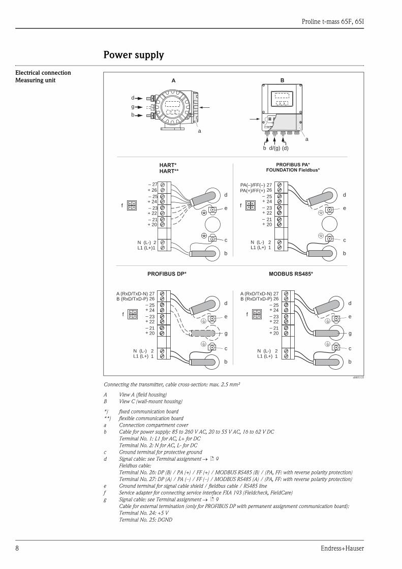
a0005135
Connecting the transmitter, cable cross-section: max. 2.5 mm²
A View A (field housing)
B View C (wall-mount housing)
*) fixed communication board
**) flexible communication board
a Connection compartment cover
b Cable for power supply: 85 to 260 V AC, 20 to 55 V AC, 16 to 62 V DC
Terminal No. 1: L1 for AC, L+ for DC
Terminal No. 2: N for AC, L- for DC
c Ground terminal for protective ground
d Signal cable: see Terminal assignment → ä 9
Fieldbus cable:
Terminal No. 26: DP (B) / PA (+) / FF (+) / MODBUS RS485 (B) / (PA, FF: with reverse polarity protection)
Terminal No. 27: DP (A) / PA (–) / FF (–) / MODBUS RS485 (A) / (PA, FF: with reverse polarity protection)
e Ground terminal for signal cable shield / fieldbus cable / RS485 line
f Service adapter for connecting service interface FXA 193 (Fieldcheck, FieldCare)
g Signal cable: see Terminal assignment → ä 9
Cable for external termination (only for PROFIBUS DP with permanent assignment communication board):
Terminal No. 24: +5 V
Terminal No. 25: DGND
PROFIBUS PA*
FOUNDATION Fieldbus*
HART*
HART**
27
25
23
21
21
26
24
22
20
L1 (L+)N (L-)
–
–
–
+
+
+
PA(–)/FF(–)
27
25
23
21
21
26
24
22
20
L1 (L+)N (L-)
–
–
–
+
+
+
A (RxD/TxD-N)B (RxD/TxD-P)
PA(+)/FF(+)d
c
e
b
– 27
– 25
– 23
– 21
+ 26
+ 24
+ 22
+ 20
N (L-) 2L1 (L+)1
a
A
d
b
g
d
c
e
b
d
c
e
b
g
PROFIBUS DP*
f f
f
a
B
(d)b d/(g)
27
25
23
21
21
26
24
22
20
L1 (L+)N (L-)
–
–
–
+
+
+
A (RxD/TxD-N)B (RxD/TxD-P)
d
c
e
b
g
MODBUS RS485*
f
Proline t-mass 65F, 65I
Endress+Hauser 9
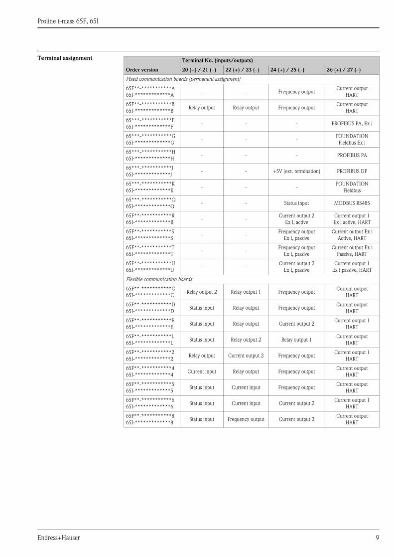
Terminal assignment Terminal No. (inputs/outputs)
Order version 20 (+) / 21 (–) 22 (+) / 23 (–) 24 (+) / 25 (–) 26 (+) / 27 (–)
Fixed communication boards (permanent assignment)
65F**-***********A
65I-*************A- - Frequency output
Current output
HART
65F**-***********B
65I-*************BRelay output Relay output Frequency output
Current output
HART
65***-***********F
65I-*************F- - - PROFIBUS PA, Ex i
65***-***********G
65I-*************G- - -
FOUNDATION
Fieldbus Ex i
65***-***********H
65I-*************H- - - PROFIBUS PA
65***-***********J
65I-*************J- - +5V (ext. termination) PROFIBUS DP
65***-***********K
65I-*************K- - -
FOUNDATION
Fieldbus
65***-***********Q
65I-*************Q- - Status input MODBUS RS485
65F**-***********R
65I-*************R- -
Current output 2
Ex i, active
Current output 1
Ex i active, HART
65F**-***********S
65I-*************S- -
Frequency output
Ex i, passive
Current output Ex i
Active, HART
65F**-***********T
65I-*************T- -
Frequency output
Ex i, passive
Current output Ex i
Passive, HART
65F**-***********U
65I-*************U- -
Current output 2
Ex i, passive
Current output 1
Ex i passive, HART
Flexible communication boards
65F**-***********C
65I-*************CRelay output 2 Relay output 1 Frequency output
Current output
HART
65F**-***********D
65I-*************DStatus input Relay output Frequency output
Current output
HART
65F**-***********E
65I-*************EStatus input Relay output Current output 2
Current output 1
HART
65F**-***********L
65I-*************LStatus input Relay output 2 Relay output 1
Current output
HART
65F**-***********2
65I-*************2Relay output Current output 2 Frequency output
Current output 1
HART
65F**-***********4
65I-*************4Current input Relay output Frequency output
Current output
HART
65F**-***********5
65I-*************5Status input Current input Frequency output
Current output
HART
65F**-***********6
65I-*************6Status input Current input Current output 2
Current output 1
HART
65F**-***********8
65I-*************8Status input Frequency output Current output 2
Current output
HART
Proline t-mass 65F, 65I
10 Endress+Hauser
Electrical connection
Remote version
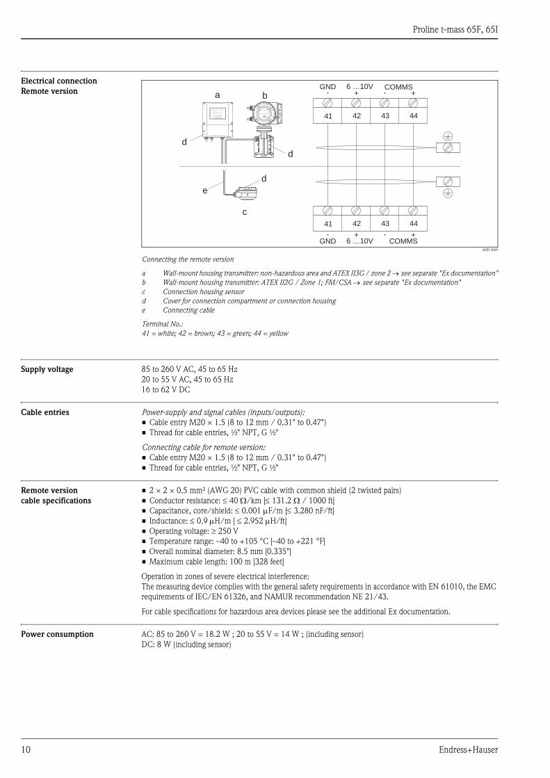
A0013669
Connecting the remote version
a Wall-mount housing transmitter: non-hazardous area and ATEX II3G / zone 2 → see separate "Ex documentation"
b Wall-mount housing transmitter: ATEX II2G / Zone 1; FM/CSA → see separate "Ex documentation"
c Connection housing sensor
d Cover for connection compartment or connection housing
e Connecting cable
Terminal No.:
41 = white; 42 = brown; 43 = green; 44 = yellow
Supply voltage 85 to 260 V AC, 45 to 65 Hz
20 to 55 V AC, 45 to 65 Hz
16 to 62 V DC
Cable entries Power-supply and signal cables (inputs/outputs):
• Cable entry M20 × 1.5 (8 to 12 mm / 0.31" to 0.47")
• Thread for cable entries, ½" NPT, G ½"
Connecting cable for remote version:
• Cable entry M20 × 1.5 (8 to 12 mm / 0.31" to 0.47")
• Thread for cable entries, ½" NPT, G ½"
Remote version
cable specifications
• 2 × 2 × 0.5 mm² (AWG 20) PVC cable with common shield (2 twisted pairs)
• Conductor resistance: ≤ 40 Ω/km [≤ 131.2 Ω / 1000 ft]
• Capacitance, core/shield: ≤ 0.001 μF/m [≤ 3.280 nF/ft]
• Inductance: ≤ 0.9 μH/m [ ≤ 2.952 μH/ft]
• Operating voltage: ≥ 250 V
• Temperature range: –40 to +105 °C [–40 to +221 °F]
• Overall nominal diameter: 8.5 mm [0.335"]
• Maximum cable length: 100 m [328 feet]
Operation in zones of severe electrical interference:
The measuring device complies with the general safety requirements in accordance with EN 61010, the EMC
requirements of IEC/EN 61326, and NAMUR recommendation NE 21/43.
For cable specifications for hazardous area devices please see the additional Ex documentation.
Power consumption AC: 85 to 260 V = 18.2 W ; 20 to 55 V = 14 W ; (including sensor)
DC: 8 W (including sensor)
a b
c
d
d
d
e
GND COMMS6 …10V+- +-
41 42 43 44
GND COMMS6 …10V+- +-
41 42 43 44
Proline t-mass 65F, 65I
Endress+Hauser 11
Power supply failure Lasting minimum 1 power cycle
• EEPROM/HistoROM T-DAT saves measuring system data if the power supply fails
• HistoROM S-DAT is on exchangeable data storage chip with sensor specific data (pipe type, nominal
diameter, serial number, flow conditioner, zero point, etc.)
• Totalizer stops at the last value determined
Potential equalization No special measures for potential equalization are required.
For instruments for use in hazardous areas, observe the corresponding guidelines in the specific Ex
documentation.
Performance characteristics
Calibration reference
conditions
• Accredited according to ISO/IEC 17025
• Traceable to National Standards
• Calibration gas: air
• Temperature controlled to 24 °C ±0.5 °C (75.2 °F ± 0.9 °F) at atmospheric pressure
• Humidity controlled < 40% RH
Maximum measured error t-mass 65F:
±1.5 % of reading for 100 % to 10 % of full scale (at reference conditions)
±0.15 % of full scale for 10 % to 1 % of full scale (at reference conditions)
t-mass 65I:
±1.0% of reading
±0.5% of full scale (at reference conditions)
Repeatability ±0.4 % of reading for velocities above 1.0 m/s (3.3 ft/s)
Influence of medium pressure
(Pressure co-efficient)
Air: 0.35% per bar (0.02% per psi) of process pressure change
Other gases: on request
Response time Typically less than 2 seconds for 63 % of a given step change (in either direction).
Proline t-mass 65F, 65I
12 Endress+Hauser
Operating conditions: InstallationThermal meters require a fully developed flow profile as a prerequisite for correct flow measurement. For this
reason, please note the following points when installing the device.
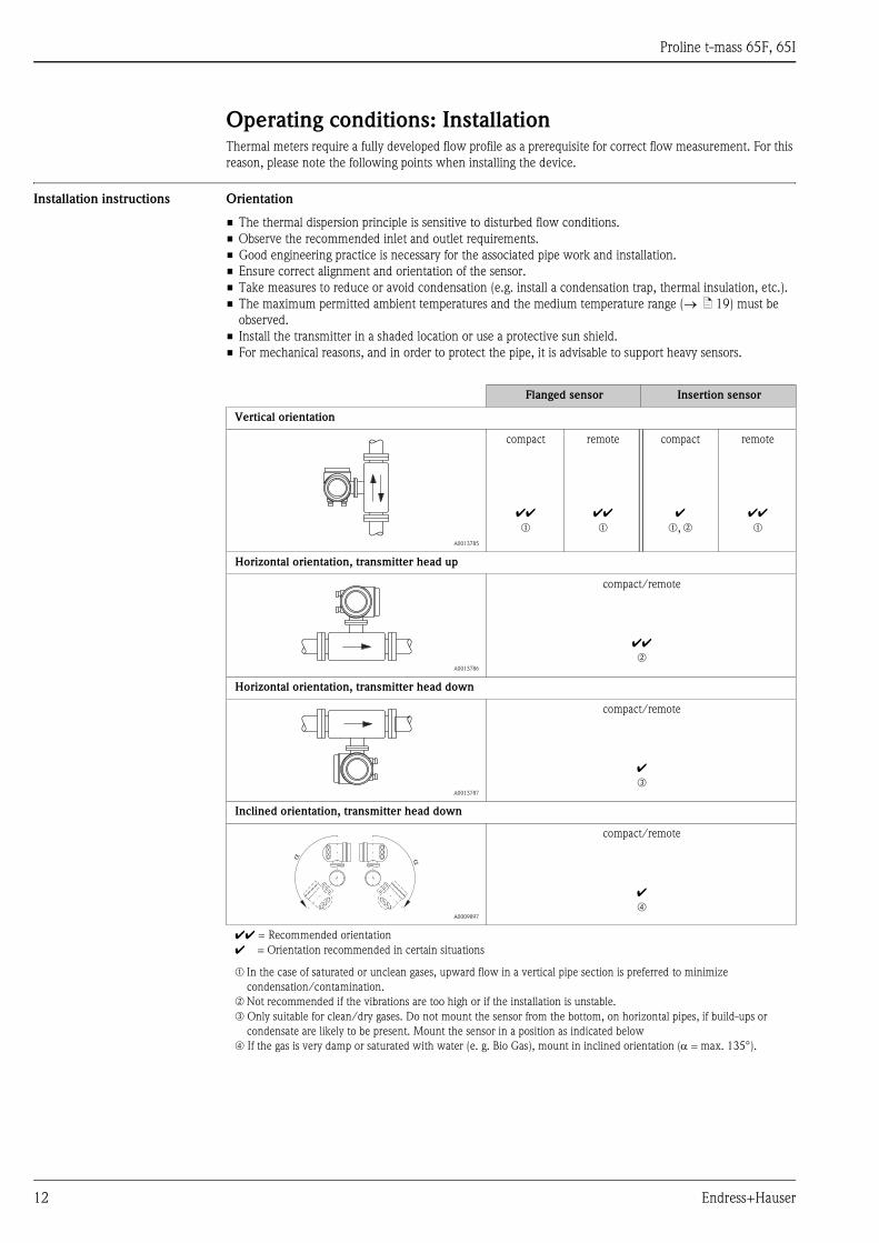
Installation instructions Orientation
• The thermal dispersion principle is sensitive to disturbed flow conditions.
• Observe the recommended inlet and outlet requirements.
• Good engineering practice is necessary for the associated pipe work and installation.
• Ensure correct alignment and orientation of the sensor.
• Take measures to reduce or avoid condensation (e.g. install a condensation trap, thermal insulation, etc.).
• The maximum permitted ambient temperatures and the medium temperature range (→ ä 19) must be
observed.
• Install the transmitter in a shaded location or use a protective sun shield.
• For mechanical reasons, and in order to protect the pipe, it is advisable to support heavy sensors.
Flanged sensor Insertion sensor
Vertical orientation
A0013785
compact
ÃÃm
remote
ÃÃm
compact
Ãm, n
remote
ÃÃm
Horizontal orientation, transmitter head up
A0013786
compact/remote
ÃÃn
Horizontal orientation, transmitter head down
A0013787
compact/remote
Ão
Inclined orientation, transmitter head down
A0009897
compact/remote
Ãp
ÃÃ = Recommended orientation
à = Orientation recommended in certain situations
m In the case of saturated or unclean gases, upward flow in a vertical pipe section is preferred to minimize
condensation/contamination.
n Not recommended if the vibrations are too high or if the installation is unstable.
o Only suitable for clean/dry gases. Do not mount the sensor from the bottom, on horizontal pipes, if build-ups or
condensate are likely to be present. Mount the sensor in a position as indicated below
p If the gas is very damp or saturated with water (e. g. Bio Gas), mount in inclined orientation (α = max. 135°).
Proline t-mass 65F, 65I
Endress+Hauser 13
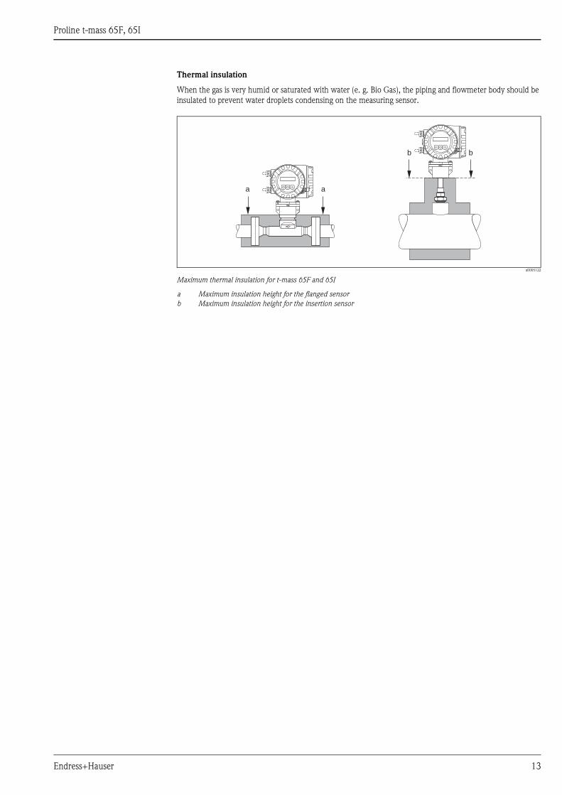
Thermal insulation
When the gas is very humid or saturated with water (e. g. Bio Gas), the piping and flowmeter body should be
insulated to prevent water droplets condensing on the measuring sensor.
a0005122
Maximum thermal insulation for t-mass 65F and 65I
a Maximum insulation height for the flanged sensor
b Maximum insulation height for the insertion sensor
a a
b b
Proline t-mass 65F, 65I
14 Endress+Hauser
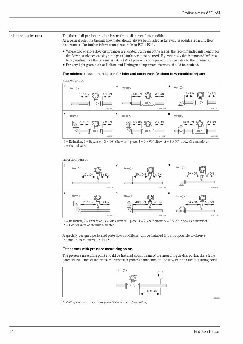
Inlet and outlet runs The thermal dispersion principle is sensitive to disturbed flow conditions.
As a general rule, the thermal flowmeter should always be installed as far away as possible from any flow
disturbances. For further information please refer to ISO 14511.
• Where two or more flow disturbances are located upstream of the meter, the recommended inlet length for
the flow disturbance causing strongest disturbance must be used. E.g. where a valve is mounted before a
bend, upstream of the flowmeter, 50 × DN of pipe work is required from the valve to the flowmeter.
• For very light gases such as Helium and Hydrogen all upstream distances should be doubled.
The minimum recommendations for inlet and outlet runs (without flow conditioner) are:
Flanged sensor
Insertion sensor
A specially designed perforated plate flow conditioner can be installed if it is not possible to observe
the inlet runs required (→ ä 15).
Outlet runs with pressure measuring points
The pressure measuring point should be installed downstream of the measuring device, so that there is no
potential influence of the pressure transmitter process connection on the flow entering the measuring point.
a0005114
Installing a pressure measuring point (PT = pressure transmitter)
1
a0007523
2
a0007524
3
a0007525
4
a0007526
5
a0007527
6
a0007528
1 = Reduction, 2 = Expansion, 3 = 90° elbow or T-piece, 4 = 2 × 90° elbow, 5 = 2 × 90° elbow (3-dimensional),
6 = Control valve
1
a0007529
2
a0007530
3
a0007531
4
a0007532
5
a0007564
6
a0007534
1 = Reduction, 2 = Expansion, 3 = 90° elbow or T-piece, 4 = 2 × 90° elbow, 5 = 2 × 90° elbow (3-dimensional),
6 = Control valve or pressure regulator
15 x DN 2 x DN 15 x DN 2 x DN 15 x DN 2 x DN
20 x DN 2 x DN 35 x DN 2 x DN 50 x DN 2 x DN
20 x DN 5 x DN 20 x DN 5 x DN 20 x DN 5 x DN
25 x DN 5 x DN 40 x DN 5 x DN 50 x DN 5 x DN
PT
2...5 x DN
Proline t-mass 65F, 65I
Endress+Hauser 15
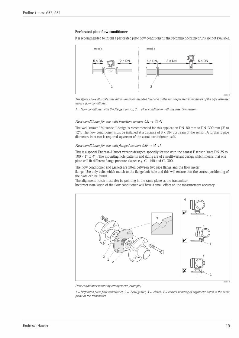
Perforated plate flow conditioner
It is recommended to install a perforated plate flow conditioner if the recommended inlet runs are not available.
a0005115
The figure above illustrates the minimum recommended inlet and outlet runs expressed in multiples of the pipe diameter
using a flow conditioner.
1 = Flow conditioner with the flanged sensor, 2 = Flow conditioner with the insertion sensor
Flow conditioner for use with insertion sensors 65I → ä 41
The well known "Mitsubishi" design is recommended for this application DN 80 mm to DN 300 mm (3" to
12"). The flow conditioner must be installed at a distance of 8 × DN upstream of the sensor. A further 5 pipe
diameters inlet run is required upstream of the actual conditioner itself.
Flow conditioner for use with flanged sensors 65F → ä 41
This is a special Endress+Hauser version designed specially for use with the t-mass F sensor (sizes DN 25 to
100 / 1" to 4"). The mounting hole patterns and sizing are of a multi-variant design which means that one
plate will fit different flange pressure classes e.g. Cl. 150 and Cl. 300.
The flow conditioner and gaskets are fitted between two pipe flange and the flow meter
flange. Use only bolts which match to the flange bolt hole and this will ensure that the correct positioning of
the plate can be found.
The alignment notch must also be pointing in the same plane as the transmitter.
Incorrect installation of the flow conditioner will have a small effect on the measurement accuracy.
a0005116
Flow conditioner mounting arrangement (example)
1 = Perforated plate flow conditioner, 2 = Seal/gasket, 3 = Notch, 4 = correct pointing of alignment notch in the same
plane as the transmitter
2 × DN5 × DN 8 × DN 5 × DN5 × DN
21
12
2
3
4
✘
Ã
Ã
1
1
1
Proline t-mass 65F, 65I
16 Endress+Hauser
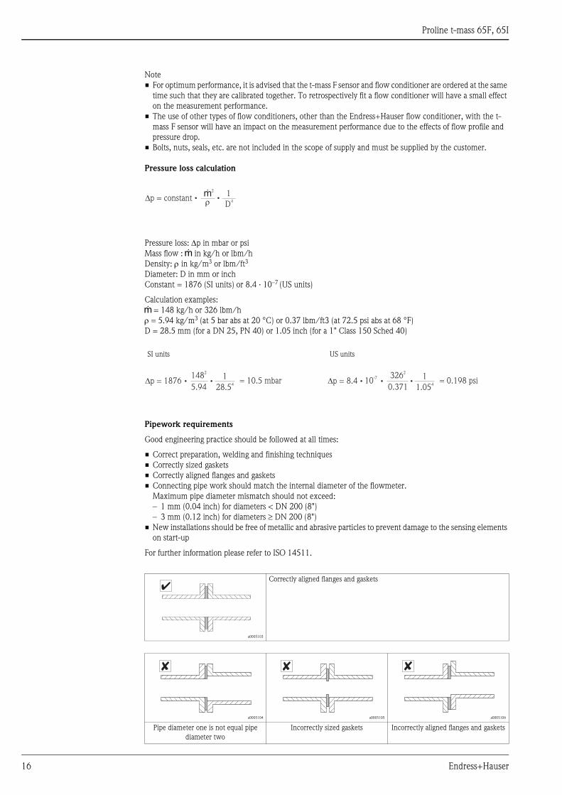
Note
• For optimum performance, it is advised that the t-mass F sensor and flow conditioner are ordered at the same
time such that they are calibrated together. To retrospectively fit a flow conditioner will have a small effect
on the measurement performance.
• The use of other types of flow conditioners, other than the Endress+Hauser flow conditioner, with the t-
mass F sensor will have an impact on the measurement performance due to the effects of flow profile and
pressure drop.
• Bolts, nuts, seals, etc. are not included in the scope of supply and must be supplied by the customer.
Pressure loss calculation
Pressure loss: Δp in mbar or psi
Mass flow : g in kg/h or lbm/h
Density: ρ in kg/m3 or lbm/ft3
Diameter: D in mm or inch
Constant = 1876 (SI units) or 8.4 · 10–7 (US units)
Calculation examples:
g = 148 kg/h or 326 lbm/h
ρ = 5.94 kg/m3 (at 5 bar abs at 20 °C) or 0.37 lbm/ft3 (at 72.5 psi abs at 68 °F)
D = 28.5 mm (for a DN 25, PN 40) or 1.05 inch (for a 1" Class 150 Sched 40)
Pipework requirements
Good engineering practice should be followed at all times:
• Correct preparation, welding and finishing techniques
• Correctly sized gaskets
• Correctly aligned flanges and gaskets
• Connecting pipe work should match the internal diameter of the flowmeter.
Maximum pipe diameter mismatch should not exceed:
– 1 mm (0.04 inch) for diameters < DN 200 (8")
– 3 mm (0.12 inch) for diameters ≥ DN 200 (8")
• New installations should be free of metallic and abrasive particles to prevent damage to the sensing elements
on start-up
For further information please refer to ISO 14511.
SI units US units
a0005103
Correctly aligned flanges and gaskets
a0005104 a0005105 a0005106
Pipe diameter one is not equal pipe
diameter two
Incorrectly sized gaskets Incorrectly aligned flanges and gaskets
�p = constantg
2
� D4
1
�p = 18761148
2
5.94 28.54
= 10.5 mbar �p = 8.41326
2
0.371 1.054
= 0.198 psi10-7
Ã
✘ ✘ ✘

Proline t-mass 65F, 65I
Endress+Hauser 17
Mounting conditions for the
insertion version
Selecting the length of the insertion sensor
The minimum required length of the insertion sensor can be determined by using Endress+Hauser's sizing tool,
Applicator (version 10.02 or later "Accessories") or according to the following calculation steps.
The minimum required length of the insertion sensor is determined by the necessary insertion depth. The
calculated insertion depth must lie within the adjustable range of the selected insertion sensor.
1. Determine the dimensions A, B, C1 and C2
A0014024
Determine the dimensions C1 and C2
2. Calculate the insertion depth
Insertion depth = (0,3 ·A) + B + (C1 + C2) + 2 mm
(Insertion depth = (0,3 ·A) + B + (C1 + C2) + 0.079 inch)
3. A suitable insertion sensor length can be determined by comparing the calculated insertion depth with
the following table. The calculated insertion depth must be within the adjusting range of the
corresponding insertion sensor length!
A = For circular pipes: the internal pipe diameter (DN)
For rectangular pipes/ducts: the inner dimension
B = Wall thickness of pipe or duct
C1+C2 = Length of mounting set and insertion tube's compression fitting
If only Endress+Hauser accessories are used
DK6MB-BXA Mounting boss G1A: C1 + C2 = 106 mm (4.173 inch)
DK6MB-AXA Mounting boss 1" NPT: C1 + C2 = 112 mm (4.409 inch)
If it is intended not to use solely Endress+Hauser accessories
C1 Height of pipe connection (mounting boss) used
C2 46mm (1.811 inch) process connection, G1A threaded fitting
52mm (2.047 inch) process connection, NPT threaded fitting
Insertion length Adjusting range (insertion depth)
G1A Thread NPT Thread
mm inch mm inch mm inch
235 9 120 to 230 4.7 to 9.0 126 to 230 4.96 to 9.0
335 13 120 to 330 4.7 to 13.0 126 to 330 4.96 to 13.0
435 17 120 to 430 4.7 to 17.0 126 to 430 4.96 to 17.0
608 24 120 to 604 4.7 to 23.8 126 to 604 4.96 to 23.8
A
B
C2
230
220
210
200
190
180
9
8
7
230
220
210
200
190
180
9
8
7
230
220
210
200
190
180
9
8
7
C1
A
B
C2
C1
Proline t-mass 65F, 65I
18 Endress+Hauser
Length of connecting cable Max. 100 m (328 feet), remote version
Operating conditions: Environment
Ambient temperature Standard: –20 °C to +60 °C (–4 °F to +140 °F)
Optional: –40 °C to +60 °C (–40 °F to +140 °F)
• Install the device in a shady location. Avoid direct sunlight, particularly in warm climatic regions.
(A protective sun cover is available on request)
• At ambient temperatures below –20 °C (–4 °F) the readability of the display may be impaired.
Storage temperature –40 to +80 °C (–40 to +176 °F), recommended: +20 °C (+68 °F)
Degree of protection Standard: IP 67 (NEMA 4X) for transmitter and sensor
Shock resistance According to IEC 60068-2-31
Vibration resistance Acceleration up to 1 g, 10 to 150 Hz, following IEC 60068-2-6
Electromagnetic compatibility
(EMC)
To IEC/EN 61326 and NAMUR recommendation NE 21
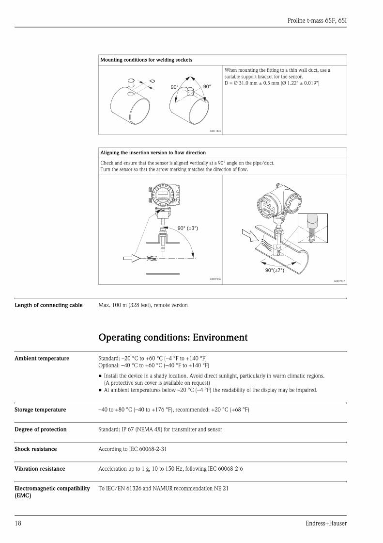
Mounting conditions for welding sockets
A0011843
When mounting the fitting to a thin wall duct, use a
suitable support bracket for the sensor.
D = Ø 31.0 mm ± 0.5 mm (Ø 1.22" ± 0.019")
Aligning the insertion version to flow direction
Check and ensure that the sensor is aligned vertically at a 90° angle on the pipe/duct.
Turn the sensor so that the arrow marking matches the direction of flow.
A0007536A0007537
90°90°
D
90° (±3°)
90°(±7°)
Proline t-mass 65F, 65I
Endress+Hauser 19
Operating conditions: Process
Medium temperature range Sensor
t-mass F:
–40 °C to +100 °C (–40 °F to +212 °F)
t-mass I:
–40 °C to +130 °C (–40 °F to +266 °F)
Seals t-mass F
O-rings:
Viton FKM –20°C to +100°C (–4°F to +212°F)
Kalrez –20°C to +100°C (–4°F to +212°F)
EPDM –40°C to +100°C (–40°F to +212°F)
Bushing:
PEEK, PVDF –40°C to +100°C (–40°F to +212°F)
Seals t-mass I
Bonded seals:
Kalrez –20°C to +130°C (–4°F to +266°F)
EPDM –40°C to +130°C (–40°F to +266°F)
Nitrile –35°C to +130°C (–31°F to +266°F)
Ferrule:
PEEK, PVDF –40°C to +130°C (–40°F to +266°F)
Pressure loss Negligible (without flow conditioner).
Refer to Applicator for the precise calculation
Medium pressure range
(nominal pressure)
t-mass F:
–0.5 to 40 bar gauge (–7.25 to 580 psi gauge)
t-mass I:
–0.5 to 20 bar gauge (–7.25 to 290 psi gauge)
Flow limit See "Measuring range" section. → ä 4
The velocity in the measuring tube should not exceed 130 m/s (427 ft/s).
Process conditions for Hot tap The Hot tap is permitted for use only with non-toxic, innocuous gases classified as "Group II" in accordance
with the European directive 67/548/EWG art. 2.
Medium pressure version
Max. process pressure: 20 bar (290 psig)
Max. extraction press: 16 bar (230 psig)
Max. extraction temperature: +50°C (+122°F)
Min. sensor length: 435 mm (17 inch)
Low pressure version
Max. process pressure: 20 bar (290 psig)
Max. extraction press: 4,5 bar (65 psig)
Max. extraction temperature: +50°C (+122°F)
Min. sensor length: 435 mm (17 inch)

Proline t-mass 65F, 65I
20 Endress+Hauser
Mechanical construction
Design, dimensions
Transmitter remote version, connection housing (II2G/Zone 1), flange version
a0005158
Dimensions "V": → ä 24 and → ä 26
Dimensions:
Transmitter remote version, connection housing (II2G/Zone 1), flange version → ä 20
Transmitter remote version, connection housing (II2G/Zone 1) → ä 21
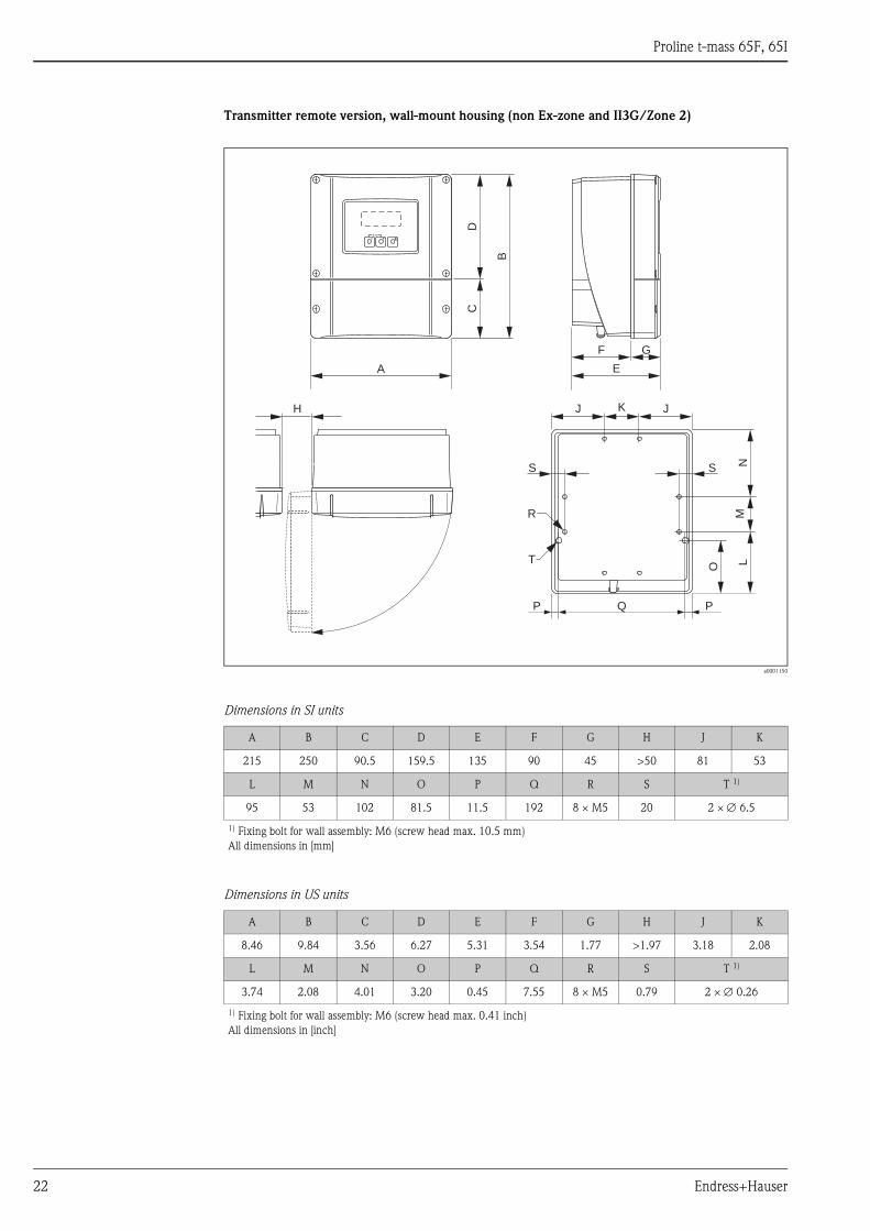
Transmitter remote version, wall-mount housing (non Ex-zone and II3G/Zone 2) → ä 22
Installing the wall-mount housing → ä 23
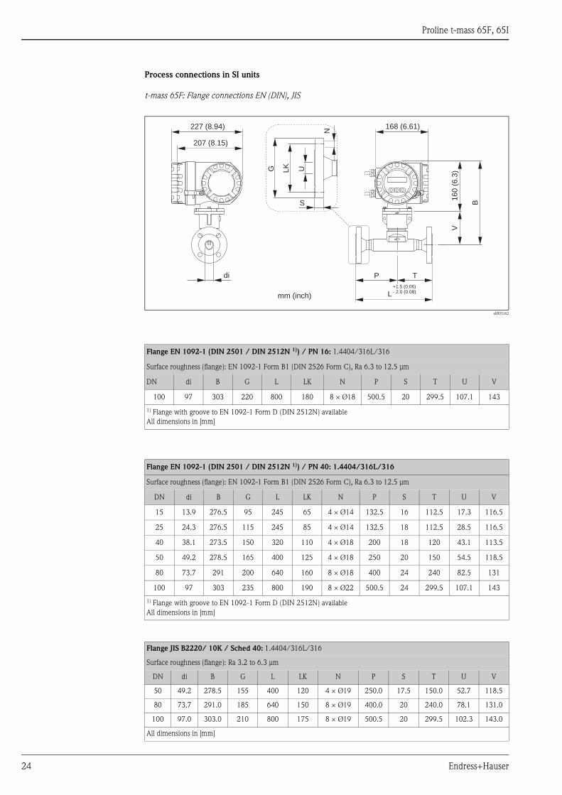
Process connections in SI units
t-mass 65F: Flange connections EN (DIN), JIS → ä 24
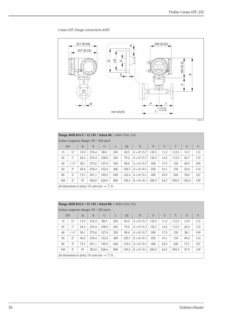
t-mass 65F: Flange connections ANSI → ä 26
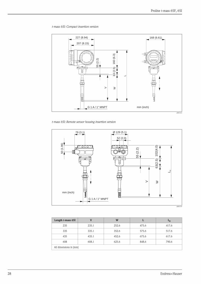
t-mass 65I: Compact insertion version → ä 28
t-mass 65I: Remote sensor housing insertion version → ä 28
Flow conditioner according to EN (DIN) / JIS / ANSI → ä 29
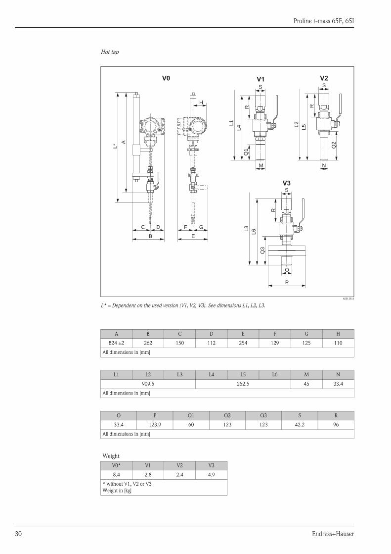
Hot tap → ä 30
Process connections in US units
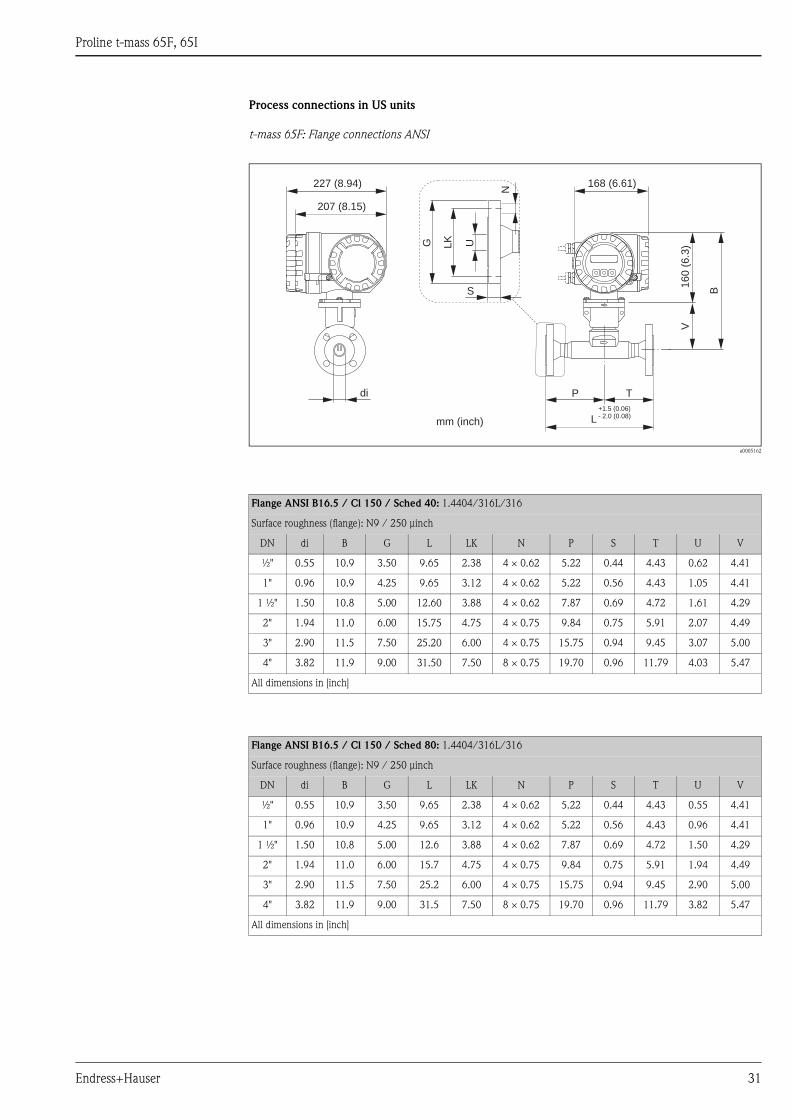
t-mass 65F: Flange connections ANSI → ä 31
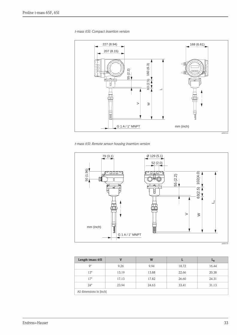
t-mass 65I: Compact insertion version → ä 33
t-mass 65I: Remote sensor housing insertion version → ä 33
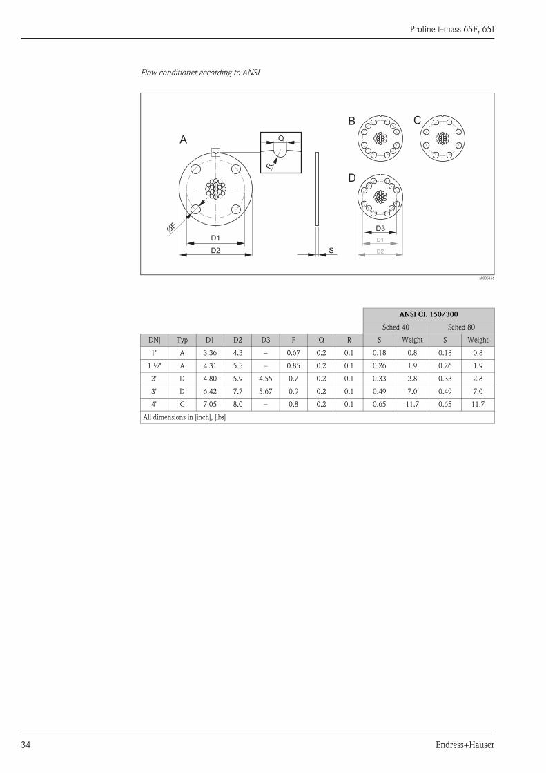
Flow conditioner according to ANSI → ä 34
Hot tap → ä 35
V1
02
(4.0
)
Ø 129 (5.1)
52 (2.0)
79 (3.1)
50
(1.9
6)
mm (inch)
Proline t-mass 65F, 65I
Endress+Hauser 21
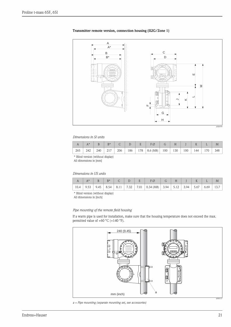
Transmitter remote version, connection housing (II2G/Zone 1)
a0006999
Dimensions in SI units
Dimensions in US units
Pipe mounting of the remote field housing
If a warm pipe is used for installation, make sure that the housing temperature does not exceed the max.
permitted value of +60 °C (+140 °F).
a0005157
a = Pipe mounting (separate mounting set, see accessories)
A A* B B* C D E F ∅ G H J K L M
265 242 240 217 206 186 178 8.6 (M8) 100 130 100 144 170 348
* Blind version (without display)
All dimensions in [mm]
A A* B B* C D E F ∅ G H J K L M
10.4 9.53 9.45 8.54 8.11 7.32 7.01 0.34 (M8) 3.94 5.12 3.94 5.67 6.69 13.7
* Blind version (without display)
All dimensions in [inch]
Nicht unter Spannungöffnen
Keep
cover
tightw
hile
circuit s
are
alive
Nepasouvrirl’appareil soustension
Keep
cove
rtightw
hile
circ
uits
are
aliv
e
Nicht-eigensichereStromkreise durch
IP40-Abdeckung geschützt
Non-intrinsically safecircuits Ip40 protected
Boucles de courantsans sécurité intrinsèque
protégées par Ip40
B*
B
A*
A
F
G
D
C
H
J K
L
M
EEsc
E+–
Nicht unter Spannungöffnen
Keep
cover
tightw
hile
circuits
are
alive
Nepasouvrirl’appareil soustension
Keep
cover
tig
htw
hile
circ
uits
are
aliv
e
Nicht-eigensichereStromkreise durch
IP40-Abdeckung geschützt
Non-intrinsically safecircuits Ip40 protected
Boucles de courantsans sécurité intrinsèque
protégées par Ip40
a
240 (9.45)
mm (inch)
Proline t-mass 65F, 65I
22 Endress+Hauser
Transmitter remote version, wall-mount housing (non Ex-zone and II3G/Zone 2)
a0001150
Dimensions in SI units
Dimensions in US units
A B C D E F G H J K
215 250 90.5 159.5 135 90 45 >50 81 53
L M N O P Q R S T 1)
95 53 102 81.5 11.5 192 8 × M5 20 2 × ∅ 6.5
1) Fixing bolt for wall assembly: M6 (screw head max. 10.5 mm)
All dimensions in [mm]
A B C D E F G H J K
8.46 9.84 3.56 6.27 5.31 3.54 1.77 >1.97 3.18 2.08
L M N O P Q R S T 1)
3.74 2.08 4.01 3.20 0.45 7.55 8 × M5 0.79 2 × ∅ 0.26
1) Fixing bolt for wall assembly: M6 (screw head max. 0.41 inch)
All dimensions in [inch]
Esc
E- +
DC
B
A
F
E
G
KJ
Q
NLO
R
H J
M
P P
SS
T
Proline t-mass 65F, 65I
Endress+Hauser 23
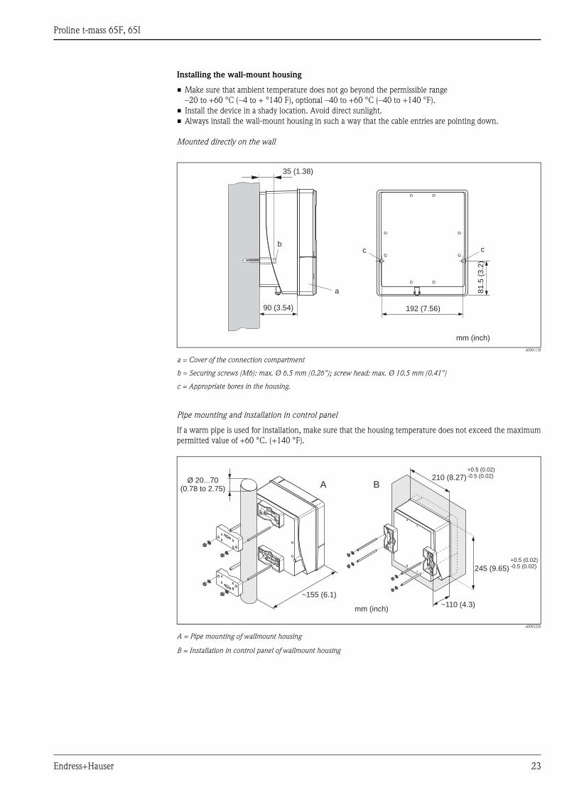
Installing the wall-mount housing
• Make sure that ambient temperature does not go beyond the permissible range
–20 to +60 °C (–4 to + °140 F), optional –40 to +60 °C (–40 to +140 °F).
• Install the device in a shady location. Avoid direct sunlight.
• Always install the wall-mount housing in such a way that the cable entries are pointing down.
Mounted directly on the wall
a0001130
a = Cover of the connection compartment
b = Securing screws (M6): max. Ø 6.5 mm (0.26"); screw head: max. Ø 10.5 mm (0.41")
c = Appropriate bores in the housing.
Pipe mounting and installation in control panel
If a warm pipe is used for installation, make sure that the housing temperature does not exceed the maximum
permitted value of +60 °C. (+140 °F).
a0005256
A = Pipe mounting of wallmount housing
B = Installation in control panel of wallmount housing
a
bc c
90 (3.54)
35 (1.38)
192 (7.56)
81
.5(3
.2)
mm (inch)
A B
245 (9.65)
+0.5 (0.02)-0.5 (0.02)
210 (8.27)+0.5 (0.02)-0.5 (0.02)
Ø 20...70(0.78 to 2.75)
~110 (4.3)
~155 (6.1)
mm (inch)
Proline t-mass 65F, 65I
24 Endress+Hauser
Process connections in SI units
t-mass 65F: Flange connections EN (DIN), JIS
a0005162
Flange EN 1092-1 (DIN 2501 / DIN 2512N 1)) / PN 16: 1.4404/316L/316
Surface roughness (flange): EN 1092-1 Form B1 (DIN 2526 Form C), Ra 6.3 to 12.5 μm
DN di B G L LK N P S T U V
100 97 303 220 800 180 8 × Ø18 500.5 20 299.5 107.1 143
1) Flange with groove to EN 1092-1 Form D (DIN 2512N) available
All dimensions in [mm]
Flange EN 1092-1 (DIN 2501 / DIN 2512N 1)) / PN 40: 1.4404/316L/316
Surface roughness (flange): EN 1092-1 Form B1 (DIN 2526 Form C), Ra 6.3 to 12.5 μm
DN di B G L LK N P S T U V
15 13.9 276.5 95 245 65 4 × Ø14 132.5 16 112.5 17.3 116.5
25 24.3 276.5 115 245 85 4 × Ø14 132.5 18 112.5 28.5 116.5
40 38.1 273.5 150 320 110 4 × Ø18 200 18 120 43.1 113.5
50 49.2 278.5 165 400 125 4 × Ø18 250 20 150 54.5 118.5
80 73.7 291 200 640 160 8 × Ø18 400 24 240 82.5 131
100 97 303 235 800 190 8 × Ø22 500.5 24 299.5 107.1 143
1) Flange with groove to EN 1092-1 Form D (DIN 2512N) available
All dimensions in [mm]
Flange JIS B2220/ 10K / Sched 40: 1.4404/316L/316
Surface roughness (flange): Ra 3.2 to 6.3 μm
DN di B G L LK N P S T U V
50 49.2 278.5 155 400 120 4 × Ø19 250.0 17.5 150.0 52.7 118.5
80 73.7 291.0 185 640 150 8 × Ø19 400.0 20 240.0 78.1 131.0
100 97.0 303.0 210 800 175 8 × Ø19 500.5 20 299.5 102.3 143.0
All dimensions in [mm]
G LK U
N
S
L
P T
B
V
di
227 (8.94)
207 (8.15)
168 (6.61)
16
0(6
.3)
+1.5 (0.06)- 2.0 (0.08)
mm (inch)
Proline t-mass 65F, 65I
Endress+Hauser 25
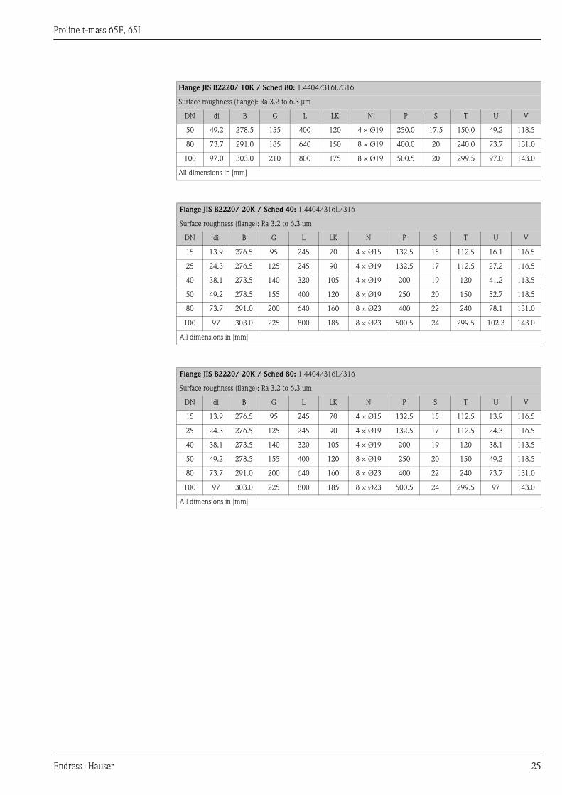
Flange JIS B2220/ 10K / Sched 80: 1.4404/316L/316
Surface roughness (flange): Ra 3.2 to 6.3 μm
DN di B G L LK N P S T U V
50 49.2 278.5 155 400 120 4 × Ø19 250.0 17.5 150.0 49.2 118.5
80 73.7 291.0 185 640 150 8 × Ø19 400.0 20 240.0 73.7 131.0
100 97.0 303.0 210 800 175 8 × Ø19 500.5 20 299.5 97.0 143.0
All dimensions in [mm]
Flange JIS B2220/ 20K / Sched 40: 1.4404/316L/316
Surface roughness (flange): Ra 3.2 to 6.3 μm
DN di B G L LK N P S T U V
15 13.9 276.5 95 245 70 4 × Ø15 132.5 15 112.5 16.1 116.5
25 24.3 276.5 125 245 90 4 × Ø19 132.5 17 112.5 27.2 116.5
40 38.1 273.5 140 320 105 4 × Ø19 200 19 120 41.2 113.5
50 49.2 278.5 155 400 120 8 × Ø19 250 20 150 52.7 118.5
80 73.7 291.0 200 640 160 8 × Ø23 400 22 240 78.1 131.0
100 97 303.0 225 800 185 8 × Ø23 500.5 24 299.5 102.3 143.0
All dimensions in [mm]
Flange JIS B2220/ 20K / Sched 80: 1.4404/316L/316
Surface roughness (flange): Ra 3.2 to 6.3 μm
DN di B G L LK N P S T U V
15 13.9 276.5 95 245 70 4 × Ø15 132.5 15 112.5 13.9 116.5
25 24.3 276.5 125 245 90 4 × Ø19 132.5 17 112.5 24.3 116.5
40 38.1 273.5 140 320 105 4 × Ø19 200 19 120 38.1 113.5
50 49.2 278.5 155 400 120 8 × Ø19 250 20 150 49.2 118.5
80 73.7 291.0 200 640 160 8 × Ø23 400 22 240 73.7 131.0
100 97 303.0 225 800 185 8 × Ø23 500.5 24 299.5 97 143.0
All dimensions in [mm]
Proline t-mass 65F, 65I
26 Endress+Hauser
t-mass 65F: Flange connections ANSI
a0005162
Flange ANSI B16.5 / Cl 150 / Sched 40: 1.4404/316L/316
Surface roughness (flange): N9 / 250 μinch
DN di B G L LK N P S T U V
15 ½" 13.9 276.4 88.9 245 60.5 4 × Ø 15.7 132.5 11.2 112.5 15.7 112
25 1" 24.3 276.4 108.0 245 79.2 4 × Ø 15.7 132.5 14.2 112.5 26.7 112
40 1 ½" 38.1 273.6 127.0 320 98.6 4 × Ø 15.7 200 17.5 120 40.9 109
50 2" 49.2 278.4 152.4 400 120.7 4 × Ø 19.1 250 19.1 150 52.6 114
80 3" 73.7 291.1 190.5 640 152.4 4 × Ø 19.1 400 23.9 240 78.0 127
100 4" 97 303.0 228.6 800 190.5 8 × Ø 19.1 500.5 24.5 299.5 102.4 139
All dimensions in [mm]. US units see → ä 31.
Flange ANSI B16.5 / Cl 150 / Sched 80: 1.4404/316L/316
Surface roughness (flange): N9 / 250 μinch
DN di B G L LK N P S T U V
15 ½" 13.9 276.4 88.9 245 60.5 4 × Ø 15.7 132.5 11.2 112.5 13.9 112
25 1" 24.3 276.4 108.0 245 79.2 4 × Ø 15.7 132.5 14.2 112.5 24.3 112
40 1 ½" 38.1 273.6 127.0 320 98.6 4 × Ø 15.7 200 17.5 120 38.1 109
50 2" 49.2 278.4 152.4 400 120.7 4 × Ø 19.1 250 19.1 150 49.2 114
80 3" 73.7 291.1 190.5 640 152.4 4 × Ø 19.1 400 23.9 240 73.7 127
100 4" 97 303.0 228.6 800 190.5 8 × Ø 19.1 500.5 24.5 299.5 97.0 139
All dimensions in [mm]. US units see → ä 31.
G LK U
N
S
L
P T
B
V
di
227 (8.94)
207 (8.15)
168 (6.61)
16
0(6
.3)
+1.5 (0.06)- 2.0 (0.08)
mm (inch)
Proline t-mass 65F, 65I
Endress+Hauser 27
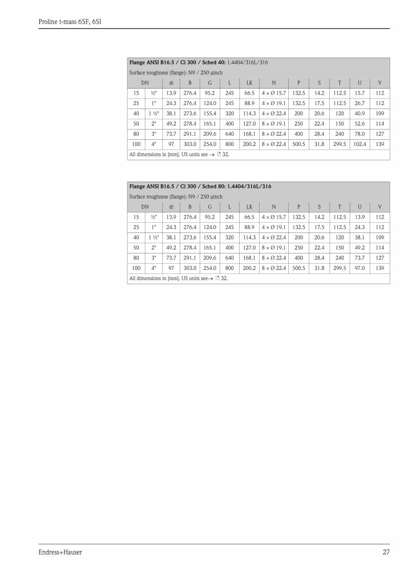
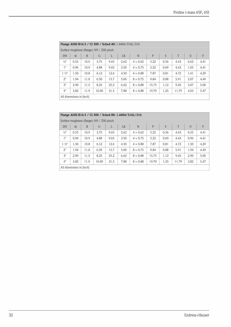
Flange ANSI B16.5 / Cl 300 / Sched 40: 1.4404/316L/316
Surface roughness (flange): N9 / 250 μinch
DN di B G L LK N P S T U V
15 ½" 13.9 276.4 95.2 245 66.5 4 × Ø 15.7 132.5 14.2 112.5 15.7 112
25 1" 24.3 276.4 124.0 245 88.9 4 × Ø 19.1 132.5 17.5 112.5 26.7 112
40 1 ½" 38.1 273.6 155.4 320 114.3 4 × Ø 22.4 200 20.6 120 40.9 109
50 2" 49.2 278.4 165.1 400 127.0 8 × Ø 19.1 250 22.4 150 52.6 114
80 3" 73.7 291.1 209.6 640 168.1 8 × Ø 22.4 400 28.4 240 78.0 127
100 4" 97 303.0 254.0 800 200.2 8 × Ø 22.4 500.5 31.8 299.5 102.4 139
All dimensions in [mm]. US units see → ä 32.
Flange ANSI B16.5 / Cl 300 / Sched 80: 1.4404/316L/316
Surface roughness (flange): N9 / 250 μinch
DN di B G L LK N P S T U V
15 ½" 13.9 276.4 95.2 245 66.5 4 × Ø 15.7 132.5 14.2 112.5 13.9 112
25 1" 24.3 276.4 124.0 245 88.9 4 × Ø 19.1 132.5 17.5 112.5 24.3 112
40 1 ½" 38.1 273.6 155.4 320 114.3 4 × Ø 22.4 200 20.6 120 38.1 109
50 2" 49.2 278.4 165.1 400 127.0 8 × Ø 19.1 250 22.4 150 49.2 114
80 3" 73.7 291.1 209.6 640 168.1 8 × Ø 22.4 400 28.4 240 73.7 127
100 4" 97 303.0 254.0 800 200.2 8 × Ø 22.4 500.5 31.8 299.5 97.0 139
All dimensions in [mm]. US units see→ ä 32.
Proline t-mass 65F, 65I
28 Endress+Hauser
t-mass 65I: Compact insertion version
a0005163
t-mass 65I: Remote sensor housing insertion version
a0005159
Length t-mass 65I V W L LR
235 235.1 252.6 475.6 417.6
335 335.1 352.6 575.6 517.6
435 435.1 452.6 675.6 617.6
608 608.1 625.6 848.6 790.6
All dimensions in [mm]
G 1 A / 1" MNPT
L
WV
227 (8.94)
207 (8.15)
168 (6.61)
mm (inch)
16
0(6
.3)
55
(2.2
)
63
(2.5
)
G 1 A / 1" MNPT
LR
WV
Ø 129 (5.1)
52 (2.0)
79 (3.1)
50
(1.9
6)
10
2(4
.0)
55
(2.2
)
63
(2.5
)
mm (inch)

Proline t-mass 65F, 65I
Endress+Hauser 29
Flow conditioner according to EN (DIN) / JIS / ANSI
a0005166
EN (DIN)
PN 16 PN 40
DN Type D1 D2 F Q R S Weight S Weight
25 A 83 105 13 5 2.5 – – 4.5 0.3
40 A 108 135 17 5 2.5 – – 7.0 0.7
50 A 123 150 17 5 2.5 – – 8.5 1.0
80 C 158 185 17 5 2.5 – – 13.0 2.3
100 C 187 220 22 5 2.5 17.0 4.1 17.0 4.1
All dimensions in [mm], [kg]
JIS 10K/20K
Sched 40 Sched 80
DN Type D1 D2 F Q R S Weight S Weight
25 A 87 115 17 5 2.5 4.5 0.4 4.0 0.4
40 A 102 130 17 5 2.5 6.5 0.7 6.0 0.7
50 B 117 145 17 5 2.5 8.5 1.2 8.0 1.1
80 C 157 188 21 5 2.5 12.5 3.0 12.0 2.8
100 C 182 214 21 5 2.5 16.5 5.1 15.5 4.8
All dimensions in [mm], [kg]
ANSI Cl. 150/300
Sched 40 Sched 80
DN Type D1 D2 D3 F Q R S Weight S Weight
25 1" A 85.3 110 – 17.0 5 2.5 4.5 0.4 4.5 0.4
40 1 ½" A 109.5 140 – 21.5 5 2.5 6.5 0.9 6.5 0.9
50 2" D 122 150 115.5 19.0 5 2.5 8.5 1.3 8.5 1.3
80 3" D 163 195 144.0 22.0 5 2.5 12.5 3.2 12.5 3.2
100 4" C 179 228 – 20.5 5 2.5 16.5 5.3 16.5 5.3
All dimensions in [mm], [kg], US units see → ä 34
D1
D2
ØF
S
A
B C
R
Q
D
D2
D3
D1
Proline t-mass 65F, 65I
30 Endress+Hauser
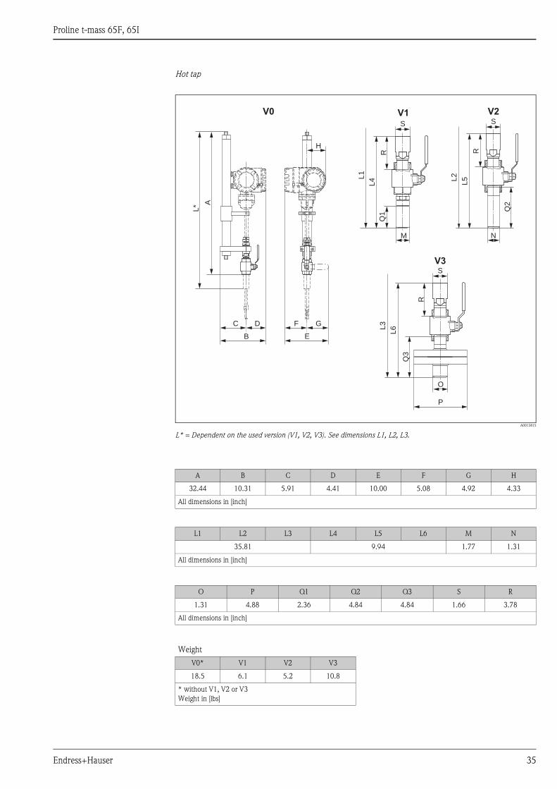
Hot tap
A0013815
L* = Dependent on the used version (V1, V2, V3). See dimensions L1, L2, L3.
L* A
C
B
D F
E
G
H
N
P
O
L5
L4
L6
V0 V2
V3
V1
L2
L3
L1
Q2
Q3
Q1
R
R
R
S
M
S
S
A B C D E F G H
824 ±2 262 150 112 254 129 125 110
All dimensions in [mm]
L1 L2 L3 L4 L5 L6 M N
909.5 252.5 45 33.4
All dimensions in [mm]
O P Q1 Q2 Q3 S R
33.4 123.9 60 123 123 42.2 96
All dimensions in [mm]
Weight
V0* V1 V2 V3
8.4 2.8 2.4 4.9
* without V1, V2 or V3
Weight in [kg]
Proline t-mass 65F, 65I
Endress+Hauser 31
Process connections in US units
t-mass 65F: Flange connections ANSI
a0005162
Flange ANSI B16.5 / Cl 150 / Sched 40: 1.4404/316L/316
Surface roughness (flange): N9 / 250 μinch
DN di B G L LK N P S T U V
½" 0.55 10.9 3.50 9.65 2.38 4 × 0.62 5.22 0.44 4.43 0.62 4.41
1" 0.96 10.9 4.25 9.65 3.12 4 × 0.62 5.22 0.56 4.43 1.05 4.41
1 ½" 1.50 10.8 5.00 12.60 3.88 4 × 0.62 7.87 0.69 4.72 1.61 4.29
2" 1.94 11.0 6.00 15.75 4.75 4 × 0.75 9.84 0.75 5.91 2.07 4.49
3" 2.90 11.5 7.50 25.20 6.00 4 × 0.75 15.75 0.94 9.45 3.07 5.00
4" 3.82 11.9 9.00 31.50 7.50 8 × 0.75 19.70 0.96 11.79 4.03 5.47
All dimensions in [inch]
Flange ANSI B16.5 / Cl 150 / Sched 80: 1.4404/316L/316
Surface roughness (flange): N9 / 250 μinch
DN di B G L LK N P S T U V
½" 0.55 10.9 3.50 9.65 2.38 4 × 0.62 5.22 0.44 4.43 0.55 4.41
1" 0.96 10.9 4.25 9.65 3.12 4 × 0.62 5.22 0.56 4.43 0.96 4.41
1 ½" 1.50 10.8 5.00 12.6 3.88 4 × 0.62 7.87 0.69 4.72 1.50 4.29
2" 1.94 11.0 6.00 15.7 4.75 4 × 0.75 9.84 0.75 5.91 1.94 4.49
3" 2.90 11.5 7.50 25.2 6.00 4 × 0.75 15.75 0.94 9.45 2.90 5.00
4" 3.82 11.9 9.00 31.5 7.50 8 × 0.75 19.70 0.96 11.79 3.82 5.47
All dimensions in [inch]
G LK U
N
S
L
P T
B
V
di
227 (8.94)
207 (8.15)
168 (6.61)
16
0(6
.3)
+1.5 (0.06)- 2.0 (0.08)
mm (inch)
Proline t-mass 65F, 65I
32 Endress+Hauser
Flange ANSI B16.5 / Cl 300 / Sched 40: 1.4404/316L/316
Surface roughness (flange): N9 / 250 μinch
DN di B G L LK N P S T U V
½" 0.55 10.9 3.75 9.65 2.62 4 × 0.62 5.22 0.56 4.43 0.62 4.41
1" 0.96 10.9 4.88 9.65 3.50 4 × 0.75 5.22 0.69 4.43 1.05 4.41
1 ½" 1.50 10.8 6.12 12.6 4.50 4 × 0.88 7.87 0.81 4.72 1.61 4.29
2" 1.94 11.0 6.50 15.7 5.00 8 × 0.75 9.84 0.88 5.91 2.07 4.49
3" 2.90 11.5 8.25 25.2 6.62 8 × 0.88 15.75 1.12 9.45 3.07 5.00
4" 3.82 11.9 10.00 31.5 7.88 8 × 0.88 19.70 1.25 11.79 4.03 5.47
All dimensions in [inch]
Flange ANSI B16.5 / Cl 300 / Sched 80: 1.4404/316L/316
Surface roughness (flange): N9 / 250 μinch
DN di B G L LK N P S T U V
½" 0.55 10.9 3.75 9.65 2.62 4 × 0.62 5.22 0.56 4.43 0.55 4.41
1" 0.96 10.9 4.88 9.65 3.50 4 × 0.75 5.22 0.69 4.43 0.96 4.41
1 ½" 1.50 10.8 6.12 12.6 4.50 4 × 0.88 7.87 0.81 4.72 1.50 4.29
2" 1.94 11.0 6.50 15.7 5.00 8 × 0.75 9.84 0.88 5.91 1.94 4.49
3" 2.90 11.5 8.25 25.2 6.62 8 × 0.88 15.75 1.12 9.45 2.90 5.00
4" 3.82 11.9 10.00 31.5 7.88 8 × 0.88 19.70 1.25 11.79 3.82 5.47
All dimensions in [inch]
Proline t-mass 65F, 65I
Endress+Hauser 33
t-mass 65I: Compact insertion version
a0005163
t-mass 65I: Remote sensor housing insertion version
a0005159
Length tmass 65I V W L LR
9" 9.26 9.94 18.72 16.44
13" 13.19 13.88 22.66 20.38
17" 17.13 17.82 26.60 24.31
24" 23.94 24.63 33.41 31.13
All dimensions in [inch]
G 1 A / 1" MNPT
L
WV
227 (8.94)
207 (8.15)
168 (6.61)
mm (inch)
16
0(6
.3)
55
(2.2
)
63
(2.5
)
G 1 A / 1" MNPT
LR
WV
Ø 129 (5.1)
52 (2.0)
79 (3.1)
50
(1.9
6)
10
2(4
.0)
55
(2.2
)
63
(2.5
)
mm (inch)
Proline t-mass 65F, 65I
34 Endress+Hauser
Flow conditioner according to ANSI
a0005166
ANSI Cl. 150/300
Sched 40 Sched 80
DN] Typ D1 D2 D3 F Q R S Weight S Weight
1" A 3.36 4.3 – 0.67 0.2 0.1 0.18 0.8 0.18 0.8
1 ½" A 4.31 5.5 – 0.85 0.2 0.1 0.26 1.9 0.26 1.9
2" D 4.80 5.9 4.55 0.7 0.2 0.1 0.33 2.8 0.33 2.8
3" D 6.42 7.7 5.67 0.9 0.2 0.1 0.49 7.0 0.49 7.0
4" C 7.05 8.0 – 0.8 0.2 0.1 0.65 11.7 0.65 11.7
All dimensions in [inch], [lbs]
D1
D2
ØF
S
A
B C
R
Q
D
D2
D3
D1
Proline t-mass 65F, 65I
Endress+Hauser 35
Hot tap
A0013815
L* = Dependent on the used version (V1, V2, V3). See dimensions L1, L2, L3.
L* A
C
B
D F
E
G
H
N
P
O
L5
L4
L6
V0 V2
V3
V1
L2
L3
L1
Q2
Q3
Q1
R
R
R
S
M
S
S
A B C D E F G H
32.44 10.31 5.91 4.41 10.00 5.08 4.92 4.33
All dimensions in [inch]
L1 L2 L3 L4 L5 L6 M N
35.81 9.94 1.77 1.31
All dimensions in [inch]
O P Q1 Q2 Q3 S R
1.31 4.88 2.36 4.84 4.84 1.66 3.78
All dimensions in [inch]
Weight
V0* V1 V2 V3
18.5 6.1 5.2 10.8
* without V1, V2 or V3
Weight in [lbs]
Proline t-mass 65F, 65I
36 Endress+Hauser
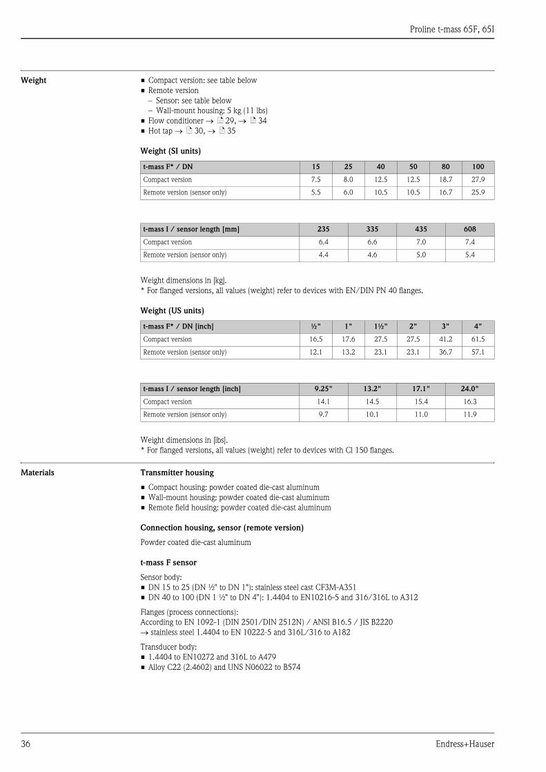
Weight • Compact version: see table below
• Remote version
– Sensor: see table below
– Wall-mount housing: 5 kg (11 lbs)
• Flow conditioner → ä 29, → ä 34
• Hot tap → ä 30, → ä 35
Weight (SI units)
Weight dimensions in [kg].
* For flanged versions, all values (weight) refer to devices with EN/DIN PN 40 flanges.
Weight (US units)
Weight dimensions in [lbs].
* For flanged versions, all values (weight) refer to devices with Cl 150 flanges.
Materials Transmitter housing
• Compact housing: powder coated die-cast aluminum
• Wall-mount housing: powder coated die-cast aluminum
• Remote field housing: powder coated die-cast aluminum
Connection housing, sensor (remote version)
Powder coated die-cast aluminum
t-mass F sensor
Sensor body:
• DN 15 to 25 (DN ½" to DN 1"): stainless steel cast CF3M-A351
• DN 40 to 100 (DN 1 ½" to DN 4"): 1.4404 to EN10216-5 and 316/316L to A312
Flanges (process connections):
According to EN 1092-1 (DIN 2501/DIN 2512N) / ANSI B16.5 / JIS B2220
→ stainless steel 1.4404 to EN 10222-5 and 316L/316 to A182
Transducer body:
• 1.4404 to EN10272 and 316L to A479
• Alloy C22 (2.4602) and UNS N06022 to B574
t-mass F* / DN 15 25 40 50 80 100
Compact version 7.5 8.0 12.5 12.5 18.7 27.9
Remote version (sensor only) 5.5 6.0 10.5 10.5 16.7 25.9
t-mass I / sensor length [mm] 235 335 435 608
Compact version 6.4 6.6 7.0 7.4
Remote version (sensor only) 4.4 4.6 5.0 5.4
t-mass F* / DN [inch] ½" 1" 1½" 2" 3" 4"
Compact version 16.5 17.6 27.5 27.5 41.2 61.5
Remote version (sensor only) 12.1 13.2 23.1 23.1 36.7 57.1
t-mass I / sensor length [inch] 9.25" 13.2" 17.1" 24.0"
Compact version 14.1 14.5 15.4 16.3
Remote version (sensor only) 9.7 10.1 11.0 11.9
Proline t-mass 65F, 65I
Endress+Hauser 37
Transducer elements:
• 1.4404 to EN10217-7 and 316L to A249 or
• 1.4404 to EN 10216-5 and 316L to A213
• Alloy C22 (2.4602) and UNS N06022 to B626
Bushing:
PEEK GF30, PVDF
O-ring seals:
EPDM, Kalrez 6375, Viton FKM
t-mass I sensor
Insertion tube:
Sensor length 235 (9"), 335 (13"), 435 (17"), 608 (24")
1.4404 to EN 10216-5 and 316/316L to A312
Transducer body:
• 1.4404 to EN10272 and 316L to A479
• Alloy C22 (2.4602) and UNS N06022 to B574
Transducer elements:
• 1.4404 to EN10217-7 and 316L to A249 or
• 1.4404 to EN 10216-5 and 316L to A213
• Alloy C22 (2.4602) and UNS N06022 to B626
Protection guard:
1.4404 to EN 10088-1 and EN 10088-2 + 2B and 316L to A666
Compression fitting:
1.4404 to EN 10272 and 316/316L to A479
Ferrules:
PEEK 450G, PVDF
Bonded seals:
EPDM, Kalrez 6375, Nitrile and 316/316L (outer ring)
Hot tap
Lower tube section:
1.4404 to EN 10272 and 316/316L to A479
Upper tube section:
1.4404 to EN 10216-5 and 316/316L to A312
Ball valve:
CF3M and CF8M
Seal:
PTFE
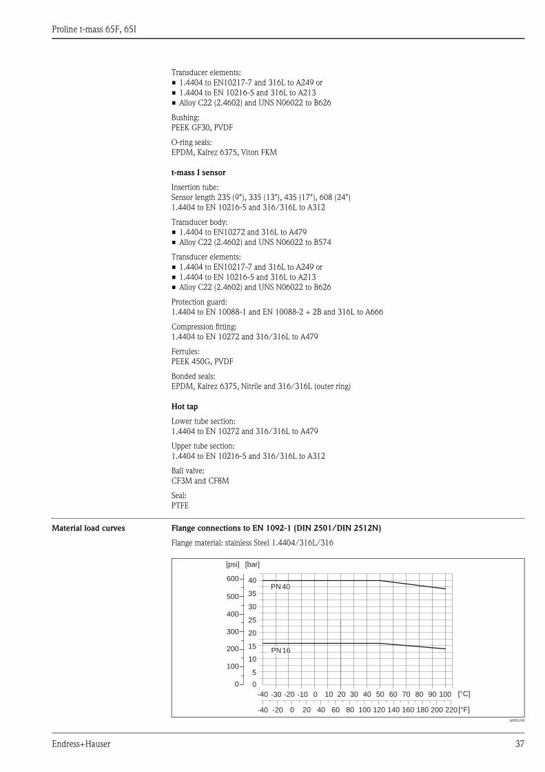
Material load curves Flange connections to EN 1092-1 (DIN 2501/DIN 2512N)
Flange material: stainless Steel 1.4404/316L/316
a0005240
0
10
20
[bar]
-40 -30 -20 -10 0 10 20 30 40 [°C]
-20 0-40 20 40 60 80 100 120 [°F]
300
400
500
600
200
100
0
[psi]
50 60 70 80 90
30
40PN 40
PN 16
140 160 180 200
100
220
5
15
25
35
Proline t-mass 65F, 65I
38 Endress+Hauser
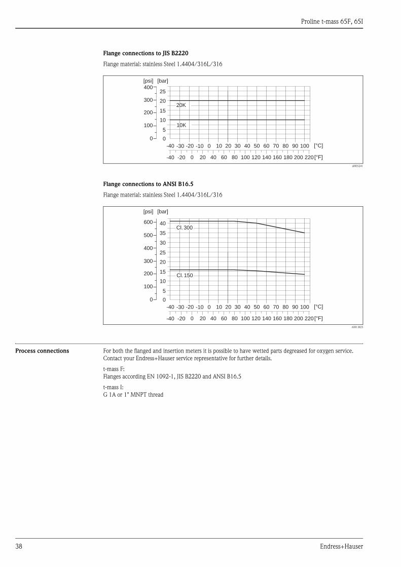
Flange connections to JIS B2220
Flange material: stainless Steel 1.4404/316L/316
a0005241
Flange connections to ANSI B16.5
Flange material: stainless Steel 1.4404/316L/316
A0013825
Process connections For both the flanged and insertion meters it is possible to have wetted parts degreased for oxygen service.
Contact your Endress+Hauser service representative for further details.
t-mass F:
Flanges according EN 1092-1, JIS B2220 and ANSI B16.5
t-mass I:
G 1A or 1" MNPT thread
0
10
20
[bar]
-40 -30 -20 -10 0 10 20 30 40 [°C]
-20 0-40 20 40 60 80 100 120 [°F]
300
200
100
0
[psi]
50 60 70 80 90
20K
10K
140 160 180 200
100
220
5
15
25400
0
10
20
[bar]
-40 -30 -20 -10 0 10 20 30 40 [°C]
-20 0-40 20 40 60 80 100 120 [°F]
300
400
500
600
200
100
0
[psi]
50 60 70 80 90
30
40Cl. 300
Cl. 150
140 160 180 200
100
220
5
15
25
35
Proline t-mass 65F, 65I
Endress+Hauser 39
Human interface
Display elements • Liquid crystal display: illuminated, two lines with 16 characters per line
• Selectable display of different measured values and status variables
• At ambient temperatures below –20 °C (–4 °F) the readability of the display may be impaired.
Operating elements • Local operation with push buttons (–, +, E)
• Quick Setup menus for straight forward commissioning
Languages English, German, French, Spanish, Italian, Dutch, Norwegian, Finnish, Swedish, Portuguese, Polish, Czech
Remote operation Operation via HART, PROFIBUS PA/DP, FOUNDATION Fieldbus, MODBUS RS485
Certificates and approvals
CE mark The measuring system is in conformity with the statutory requirements of the EC Directives.
Endress+Hauser confirms successful testing of the device by affixing to it the CE mark.
C-Tick mark The measuring system meets the EMC requirements of the Australian Communications and Media Authority
(ACMA).
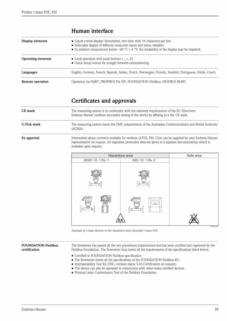
Ex approval Information about currently available Ex versions (ATEX, FM, CSA) can be supplied by your Endress+Hauser
representative on request. All explosion protection data are given in a separate documentation which is
available upon request.
a0005128-en
Example of t-mass devices in the hazardous area (Example t-mass 65F)
FOUNDATION Fieldbus
certification
The flowmeter has passed all the test procedures implemented and has been certified and registered by the
Fieldbus Foundation. The flowmeter thus meets all the requirements of the specifications listed below:
• Certified to FOUNDATION Fieldbus specification
• The flowmeter meets all the specifications of the FOUNDATION Fieldbus-H1.
• Interoperability Test Kit (ITK), revision status 5.01(Certification on request)
• The device can also be operated in conjunction with other-make certified devices.
• Physical Layer Conformance Test of the Fieldbus Foundation
Nicht unter Spannungöffnen
Keep
cover
tightw
hile
circuits
are
alive
Nepasouvrirl’appareil soustension
Keep
cove
rtightw
hile
circ
uits
are
aliv
e
Nicht unter Spannungöffnen
Keep
cover
tightw
hile
circuits
are
alive
Nepasouvrirl’appareil soustension
Keep
cove
rtightw
hile
circ
uits
are
aliv
e
II2GD / Cl. 1 Div. 1 II3G / Cl. 1 Div. 2
Esc
E- +
EX EX
Hazardous area Safe area
Proline t-mass 65F, 65I
40 Endress+Hauser
PROFIBUS DP/PA
certification
The flow device has successfully passed all the test procedures carried out and is certified and registered by the
PNO (PROFIBUS User Organization). The device thus meets all the requirements of the following
specifications:
• Certified to PROFIBUS Profile Version 3.0 (device certification number: on request)
• The device can also be operated with certified devices of other manufacturers (interoperability)
MODBUS certification The measuring device meets all the requirements of the MODBUS/TCP conformity and integration test and
has the "MODBUS/TCP Conformance Test Policy, Version 2.0". The measuring device has successfully passed
all the test procedures carried out and is certified by the "MODBUS/TCP Conformance Test Laboratory" of the
University of Michigan.
Pressure measuring device
approval
The measuring devices can be ordered with or without PED (Pressure Equipment Directive). If a device with
PED is required, this must be ordered explicitly. For devices with nominal diameters less than or equal to
DN 25 (1"), this is neither possible nor necessary.
• With the identification PED/G1/III on the sensor nameplate, Endress+Hauser confirms conformity with the
"Basic safety requirements" of Appendix I of the Pressure Equipment Directive 97/23/EC.
• Devices with this identification (with PED) are suitable for the following types of fluid:
– Fluids of Group 1 and 2 with a steam pressure of greater or less than 0.5 bar (7.3 psi)
– Unstable gases
• Devices without this identification (without PED) are designed and manufactured according to good
engineering practice. They correspond to the requirements of Art. 3, Section 3 of the Pressure Equipment
Directive 97/23/EC. Their application is illustrated in Diagrams 6 to 9 in Appendix II of the Pressure
Equipment Directive 97/23/EC.
Oxygen service We certify that the wetted parts of the flow sensor have been degreased in accordance with British Oxygen
Company (BOC) specification 0000-N-S-430-00-01 and BS IEC 60877:1999.
After final degreasing there shall be less than 100 milligram/m² (0.01 milligram/cm²) of oil/grease
contamination on the degreased surface of the component.
Other standards and
guidelines
BS IEC 60877:1999
Procedures for ensuring the cleanliness of industrial-process measurement and control equipment in oxygen
service.
EN 60529
Degrees of protection by housing (IP code)
EN 61010-1
Protection Measures for Electrical Equipment for Measurement, Control, Regulation and Laboratory
Procedures.
EN 91/155/EEC
Safety Data Sheets Directive.
IEC/EN 61326
"Emission in accordance with requirements for Class A". Electromagnetic compatibility (EMC- requirements).
ISO 14511
Measurement of fluid flow in closed conduits - Thermal mass flowmeters.
ISO/IEC 17025
General requirements for the competence of testing and calibration laboratories.
NAMUR NE 21
Electromagnetic compatibility (EMC) of industrial process and laboratory control equipment.
NAMUR NE 43
Standardization of the signal level for the breakdown information of digital transmitters with analogue output
signal.
NAMUR NE 53
Software of field devices and signal-processing devices with digital electronics
Proline t-mass 65F, 65I
Endress+Hauser 41
Ordering informationThe Endress +Hauser service organization can provide detailed ordering information and information on the
order codes on request.
To ensure each meter is programmed to individual requirements, the following information is essential:
• Gas type if not air (composition if more than one gas in % Mole)
• Gas pressure
• Gas temperature
• Line size - internal diameter in metric or US units
• 20 mA range required
• Flow engineering units (kg/h, lb/h etc.)
AccessoriesThe Endress +Hauser service organization can provide detailed information on request.
Device-specific accessories
Measuring principle-specific
accessories
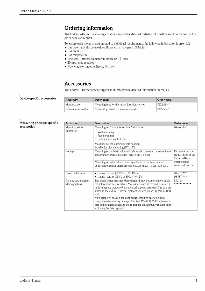
Accessory Description Order code
Mounting boss Mounting boss for the t-mass insertion version DK6MB - *
Cable remote version Connecting cable for the remote version DK6CA - *
Accessory Description Order code
Mounting set for
transmitter
Mounting set for remote version. Suitable for:
– Wall mounting
– Pipe mounting
– Installation in control panel
Mounting set for aluminum field housing:
Suitable for pipe mounting (¾" to 3")
DK6WM - *
Hot tap Mounting set with ball valve and safety chain. Insertion or extraction of
sensor under process pressure (max. 4 bar / 58 psi).
Please refer to the
product page of the
Endress+Hauser
Internet page:
www.endress.comMounting set with ball valve and spindle retractor. Insertion or
extraction of sensor under process pressure (max. 16 bar (235 psi)).
Flow conditioners • t-mass F sensor (DN25 to 100, 1"to 4")
• t-mass I sensor (DN80 to 300, 3" to 12")
DK6ST-***
DK7ST-***
Graphic data manager
Memograph M
The graphic data manager Memograph M provides information on all
the relevant process variables. Measured values are recorded correctly,
limit values are monitored and measuring points analyzed. The data are
stored in the 256 MB internal memory and also on an SD card or USB
stick.
Memograph M boasts a modular design, intuitive operation and a
comprehensive security concept. The ReadWin® 2000 PC software is
part of the standard package and is used for configuring, visualizing and
archiving the data captured.
RSG40 -
************
Proline t-mass 65F, 65I
42 Endress+Hauser
Service-specific accessories
Communication-specific
accessories
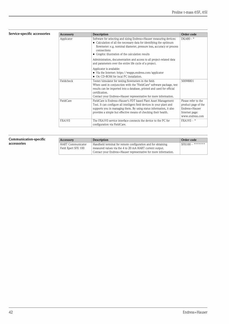
Accessory Description Order code
Applicator Software for selecting and sizing Endress+Hauser measuring devices:
• Calculation of all the necessary data for identifying the optimum
flowmeter: e.g. nominal diameter, pressure loss, accuracy or process
connections
• Graphic illustration of the calculation results
Administration, documentation and access to all project-related data
and parameters over the entire life cycle of a project.
Applicator is available:
• Via the Internet: https://wapps.endress.com/applicator
• On CD-ROM for local PC installation.
DKA80 - *
Fieldcheck Tester/simulator for testing flowmeters in the field.
When used in conjunction with the "FieldCare" software package, test
results can be imported into a database, printed and used for official
certification.
Contact your Endress+Hauser representative for more information.
50098801
FieldCare FieldCare is Endress+Hauser's FDT based Plant Asset Management
Tool. It can configure all intelligent field devices in your plant and
supports you in managing them. By using status information, it also
provides a simple but effective means of checking their health.
Please refer to the
product page of the
Endress+Hauser
Internet page:
www.endress.com
FXA193 The FXA193 service interface connects the device to the PC for
configuration via FieldCare.
FXA193 – *
Accessory Description Order code
HART Communicator
Field Xpert SFX 100
Handheld terminal for remote configuration and for obtaining
measured values via the 4 to 20 mA HART current output.
Contact your Endress+Hauser representative for more information.
SFX100 – *******
Proline t-mass 65F, 65I
Endress+Hauser 43
Documentation• Flow measuring technology (FA005D)
• Technical Information (TI069D/06)
• Operating Instructions HART (BA111D/06)
• Operating Instructions PROFIBUS DP (BA113D/06)
• Operating Instructions MODBUS (BA115D/06)
• Description of Device Functions HART (BA112D/06)
• Description of Device Functions PROFIBUS DP (BA114D/06)
• Description of Device Functions MODBUS (BA116D/06)
• Supplementary documentation on Ex-ratings: ATEX, FM, CSA, IECEx NEPSI
Registered trademarksKALREZ® and VITON®
Registered trademarks of E.I. Du Pont de Nemours & Co., Wilmington, USA
AMS™
Registered trademark of Emmerson Process Management, St. Louis, USA
HART®
Registered trademark of HART Communication Foundation, Austin, USA
PROFIBUS®
Registered trademark of the PROFIBUS User Organisation, Karlsruhe, Germany
FOUNDATION™ Fieldbus
Registered trademark of the Fieldbus FOUNDATION, Austin, USA
MODBUS®
Registered trademark of the MODBUS Organisation
HistoROM™, S-DAT®, T-DAT™, F-CHIP®, FieldCare®, Field XpertTM, Fieldcheck®,
Applicator®, t-mass®
Registered or registration-pending trademarks of Endress+Hauser Flowtec AG, Reinach, CH

Instruments International
Endress+HauserInstruments International AGKaegenstrasse 24153 ReinachSwitzerland
Tel. +41 61 715 81 00Fax +41 61 715 25 [email protected]
TI069D/06/en/06.10
71115124
FM/SGML 6.0


![F+DG] ` 3 )dg&O^ 65I [ ( 4 - erca.go.jp...·µiEh³ b± À¢² ¢ . g ¿ • ÖÌÛÇ˵G ^ ¶UDû¯LP´ ©¯¸© 1, 2, 3, ÖÎÅÄp°Iah´ ¾ÁÀ ,¶ :Ã6¥»µµ* h³ ±³¯](https://img.pdfslide.us/doc/110x75/608896deddccf126d57a2c5a/-fdg-3-dgo-65i-4-ercagojp-ieh-b-g-a.jpg)


![J org Pretz arXiv:2005.12203v1 [physics.class-ph] 25 May 2020 › pdf › 2005.12203.pdf · (t)/ m mass 1 mass 2 mass 3 mass 4 mass 5 mass 6 mass 7 mass 8 mass 9 mass 10 Figure 2](https://img.pdfslide.us/doc/110x75/5f1ec529f26656179f60ee75/j-org-pretz-arxiv200512203v1-25-may-2020-a-pdf-a-200512203pdf-t.jpg)