Embed Size (px)
Citation preview
© 2020 All rights reservedFor the most recent version of this manual please visit
dtm-medical.eu/en/support/slideprintersupport.html
062812-511311U
SE
R’S
M
AN
UA
L
ii
Notices: The information in this document is subject to change without notice. NO WARRANTY OFANY KIND IS MADE WITH REGARD TO THIS MATERIAL, INCLUDING, BUT NOT LIMITED TO,THE IMPLIED WARRANTIES OF MERCHANTABILITY AND FITNESS FOR A PARTICULAR PUR-POSE. No liability is assumed for errors contained herein or for incidental or consequential damages in connection with the furnishing, performance, or use of this material. This document contains proprietary information that is protected by copyright. All rights are reserved. No part of this document may be photocopied, reproduced, or translated into another language without priorwritten consent.
Trademark Acknowledgments: Windows is a registered trademark of Microsoft Corporation. All other trademarks are the property of their respective owners.
Printing HistoryEdition 1.3, #041714, Copyright 2012, All rights reserved.
FCC Compliance Statement: This device complies with part 15 of the FCC rules. Operation is subjectto the following two conditions: (1) this device may not cause harmful interference, and (2) this devicemust accept any interference received, including interference that may cause undesired operation.
For Users in the United States:This product is intended to be supplied by a UL listed Direct Plug-InPower Supply marked "Class 2"or a UL listed ITE Power Supply marked "LPS" with output rated12VDC, 4.5A or higher. This equipment has been tested and found to comply with the limits for aClass A digital device, pursuant to Part 15 of the FCC Rules. In a domestic environment this productmay cause radio interference, in which case the user may be required to take adequate measures. Thisequipment generates, uses, and can radiate radio frequency energy and, if not installed and used inaccordance with the instructions, may cause harmful interference to radio communications.However, there is no guarantee that interference will not occur in a particular installation. If this equip-ment does cause harmful interference to radio or television reception, which can be determined byturning the equipment off and on, the user is encouraged to try to correct the interference by one ormore of the following measures:• Re-orient or relocate the receiving antenna.• Increase the separation between the equipment and receiver.• Connect the equipment into an outlet on a circuit different from that to which the receiver is con-
nected.• Consult the dealer or an experienced radio/TV technician for help. Use of shielded cables is
required to comply with the Class A limits of Part 15 of the FCC Rules. You are cautioned that anychanges or modifications not expressly approved in this manual could void your authority tooperate and/or obtain warranty service for this equipment.
For Users in Canada: This digital apparatus does not exceed the Class A limits for radio noise for digital apparatus set out on the Radio Interference Regulations of the Canadian Department ofCommunications. Le present appareil numerique n’emet pas de bruits radio electriques depassant les limites applicables aux appareils numeriques de la class A prescrites dans le Reglement sur lebrouillage radioelectrique edicte par le ministere des Communications du Canada.
CAUTION!TO PREVENT FIRE OR SHOCK HAZARD, DO NOT EXPOSE THE UNIT TO RAIN OR MOISTURE. TO REDUCE THE RISK OF ELECTRIC SHOCK, DO NOT REMOVE EXTERIORPANELS. NO USER-SERVICEABLE PARTS INSIDE. REFER SERVICING TO QUALIFIED SERVICE PERSONNEL. OPERATE THE UNIT WITH ONLY THE PROPER ELECTRICAL SPECIFICATIONS AS LABELED ON THE PRINTER AND AC ADAPTER.
CAUTION!USE OF CONTROLS OR ADJUSTMENTS OR PERFORMANCE OF PROCEDURES OTHERTHAN THOSE SPECIFIED HEREIN MAY RESULT IN HAZARDOUS RADIATION.
iii
Table of Contents
Section 1: Getting Started...............................................................................1A. Choosing a Good Location ................................................................1B. Unpacking and Inspection.................................................................2C. Identifying the Parts ...........................................................................3D. Slide Specifications .............................................................................5E. Connect Power ....................................................................................6F. Loading a Ribbon................................................................................7G. Loading a Slide Cartridge................................................................10H. Install the Printer Driver..................................................................13
Section 2: Printing Slides..............................................................................14A. Printing from other Programs.........................................................14B. Printer Driver Settings .....................................................................14
Section 3: Maintenance and Troubleshooting..........................................16A. Indicator Lights and Buttons .........................................................16B. Cleaning the Print Head ..................................................................17C. Replacing the Print Head.................................................................18D. Troubleshooting Print Quality........................................................20E. Repairing/Preventing Ribbon Breaks ...........................................22F. Retrieving a Broken or Stuck Slide ................................................23G. Cartridge or Ribbon Recognition Problems..................................25H. Technical Support .............................................................................26
Section 4: Technical Specifications.............................................................27

iv
Getting Started 1
Section 1: Getting Started
THANK YOU…
...for purchasing a Signature Slide Printer. The Signature SlidePrinter can significantly increase the efficiency of your labwhile helping to reduce the risk of misidentification of specimens. It prints directly onto slides, eliminating hand-writing or expensive, difficult to apply xylene-resistant labels.With impressive 300 dpi print resolution, you can print text,graphics and logos along with high-resolution linear and 2Dbar codes on every slide you process.
To begin using your Signature, please read this manual care-fully. This Operator’s Manual is a guide to the Signature SlidePrinter only. There are other accessories and software thatwork with the Signature Slide Printers. Those items are purchased separately and include their own user’s manual.
NOTE ON TERMS AND CONVENTIONS
From this point forward, the following terms and conventionswill apply:
The Signature Slide Printer will be referred to simply as thePrinter.
A. CHOOSING A GOOD LOCATION
• Place the Printer in a location with adequate air circulationto prevent internal heat build-up. You will need at least16" (41 cm) of overhead space to allow the top cover toopen freely.
• Do not place the Printer near heat sources such as radiators or air ducts, or in a place subject to direct sunlight, excessive dust, mechanical vibration or shock.
2 Getting Started
B. UNPACKING AND INSPECTION
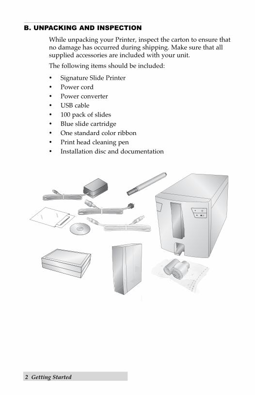
While unpacking your Printer, inspect the carton to ensure thatno damage has occurred during shipping. Make sure that allsupplied accessories are included with your unit.
The following items should be included:
• Signature Slide Printer• Power cord • Power converter• USB cable• 100 pack of slides• Blue slide cartridge• One standard color ribbon• Print head cleaning pen• Installation disc and documentation
C. INDENTIFYING THE PARTS
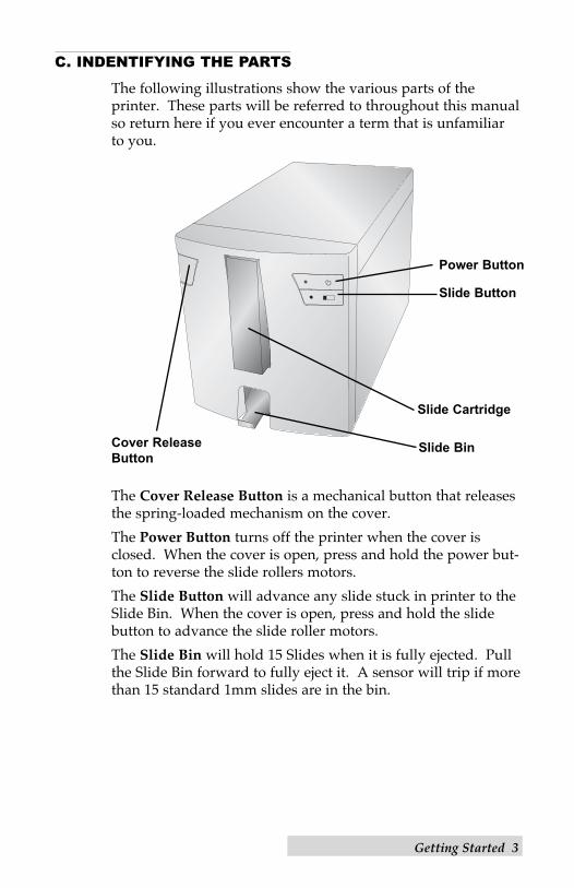
The following illustrations show the various parts of the printer. These parts will be referred to throughout this manualso return here if you ever encounter a term that is unfamiliar to you.
The Cover Release Button is a mechanical button that releasesthe spring-loaded mechanism on the cover.
The Power Button turns off the printer when the cover isclosed. When the cover is open, press and hold the power but-ton to reverse the slide rollers motors.
The Slide Button will advance any slide stuck in printer to theSlide Bin. When the cover is open, press and hold the slidebutton to advance the slide roller motors.
The Slide Bin will hold 15 Slides when it is fully ejected. Pullthe Slide Bin forward to fully eject it. A sensor will trip if morethan 15 standard 1mm slides are in the bin.
Getting Started 3
Cover Release
Button
Power Button
Slide Button
Slide Cartridge
Slide Bin
4 Getting Started
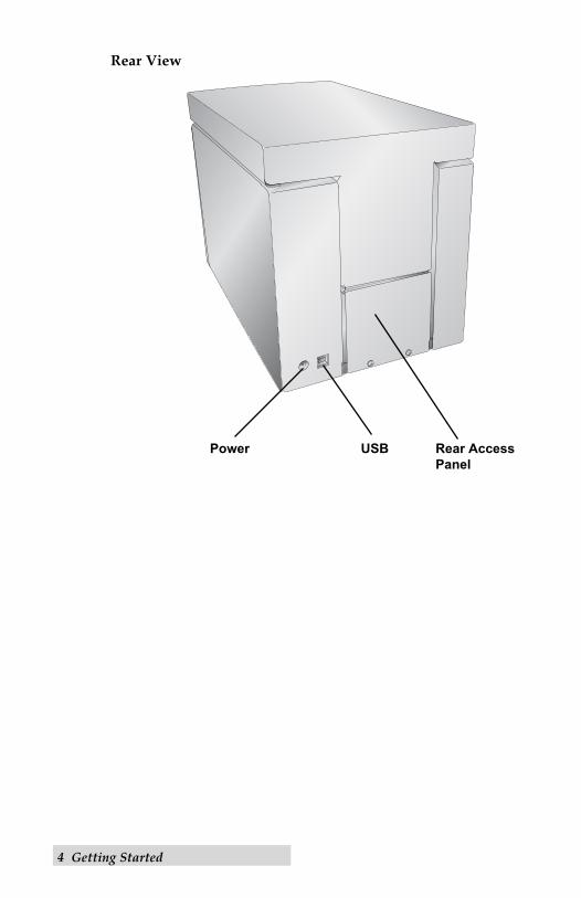
Rear View
Rear Access
Panel
USBPower
Getting Started 5
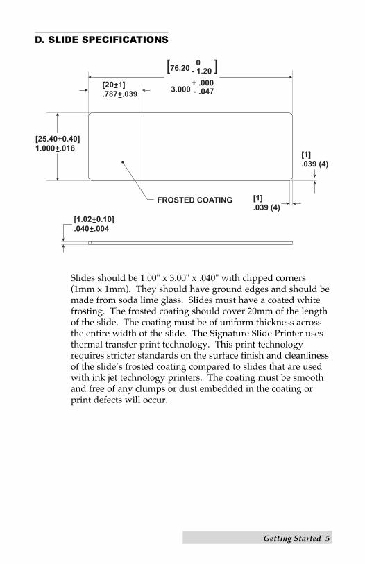
D. SLIDE SPECIFICATIONS
Slides should be 1.00" x 3.00" x .040" with clipped corners(1mm x 1mm). They should have ground edges and should bemade from soda lime glass. Slides must have a coated whitefrosting. The frosted coating should cover 20mm of the lengthof the slide. The coating must be of uniform thickness acrossthe entire width of the slide. The Signature Slide Printer usesthermal transfer print technology. This print technologyrequires stricter standards on the surface finish and cleanlinessof the slide’s frosted coating compared to slides that are usedwith ink jet technology printers. The coating must be smoothand free of any clumps or dust embedded in the coating orprint defects will occur.
[1.02+0.10].040+.004
[25.40+0.40]1.000+.016
FROSTED COATING [1].039 (4)
[1].039 (4)
[20+1].787+.039
[76.20 ] 3.000
0- 1.20+ .000 - .047
6 Getting Started
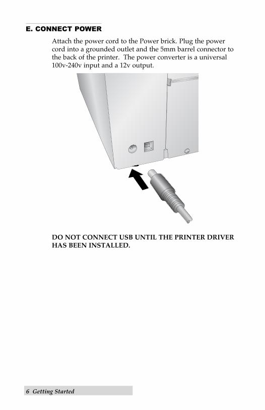
E. CONNECT POWER
Attach the power cord to the Power brick. Plug the power cord into a grounded outlet and the 5mm barrel connector tothe back of the printer. The power converter is a universal100v-240v input and a 12v output.
DO NOT CONNECT USB UNTIL THE PRINTER DRIVERHAS BEEN INSTALLED.
Getting Started 7
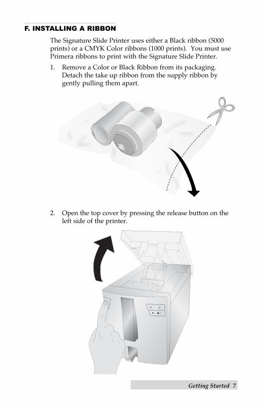
F. INSTALLING A RIBBON
The Signature Slide Printer uses either a Black ribbon (5000prints) or a CMYK Color ribbons (1000 prints). You must usePrimera ribbons to print with the Signature Slide Printer.
1. Remove a Color or Black Ribbon from its packaging.Detach the take up ribbon from the supply ribbon by gently pulling them apart.
2. Open the top cover by pressing the release button on theleft side of the printer.
8 Getting Started
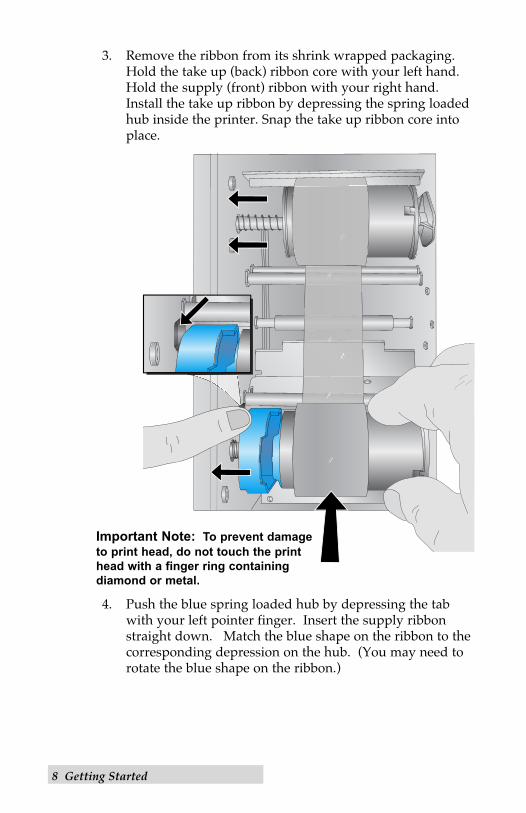
3. Remove the ribbon from its shrink wrapped packaging.Hold the take up (back) ribbon core with your left hand.Hold the supply (front) ribbon with your right hand.Install the take up ribbon by depressing the spring loadedhub inside the printer. Snap the take up ribbon core intoplace.
4. Push the blue spring loaded hub by depressing the tabwith your left pointer finger. Insert the supply ribbonstraight down. Match the blue shape on the ribbon to thecorresponding depression on the hub. (You may need torotate the blue shape on the ribbon.)
Important Note: To prevent damage
to print head, do not touch the print
head with a finger ring containing
diamond or metal.
Getting Started 9
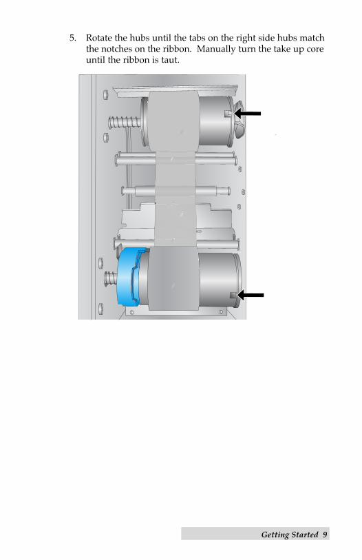
5. Rotate the hubs until the tabs on the right side hubs matchthe notches on the ribbon. Manually turn the take up coreuntil the ribbon is taut.
10 Getting Started
G. LOAD A SLIDE CARTRIDGE
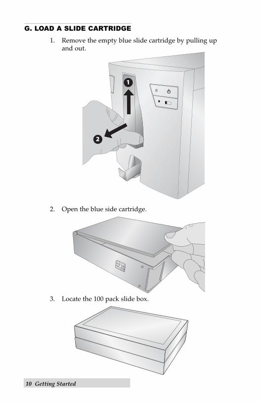
1. Remove the empty blue slide cartridge by pulling up and out.
2. Open the blue side cartridge.
3. Locate the 100 pack slide box.
Getting Started 11
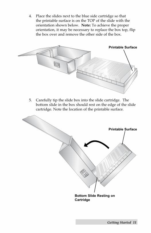
4. Place the slides next to the blue side cartridge so that the printable surface is on the TOP of the slide with the orientation shown below. Note: To achieve the proper orientation, it may be necessary to replace the box top, flipthe box over and remove the other side of the box.
5. Carefully tip the slide box into the slide cartridge. The bottom slide in the box should rest on the edge of the slidecartridge. Note the location of the printable surface.
Printable Surface
Bottom Slide Resting on
Cartridge
Printable Surface
12 Getting Started
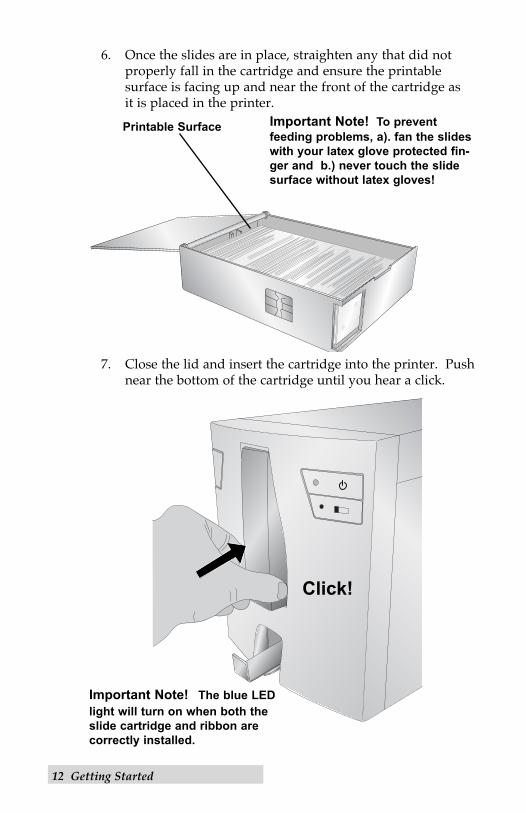
6. Once the slides are in place, straighten any that did notproperly fall in the cartridge and ensure the printable surface is facing up and near the front of the cartridge as it is placed in the printer.
7. Close the lid and insert the cartridge into the printer. Pushnear the bottom of the cartridge until you hear a click.
Click!
Important Note! The blue LED
light will turn on when both the
slide cartridge and ribbon are
correctly installed.
Important Note! To prevent
feeding problems, a). fan the slides
with your latex glove protected fin-
ger and b.) never touch the slide
surface without latex gloves!
Printable Surface
Getting Started 13
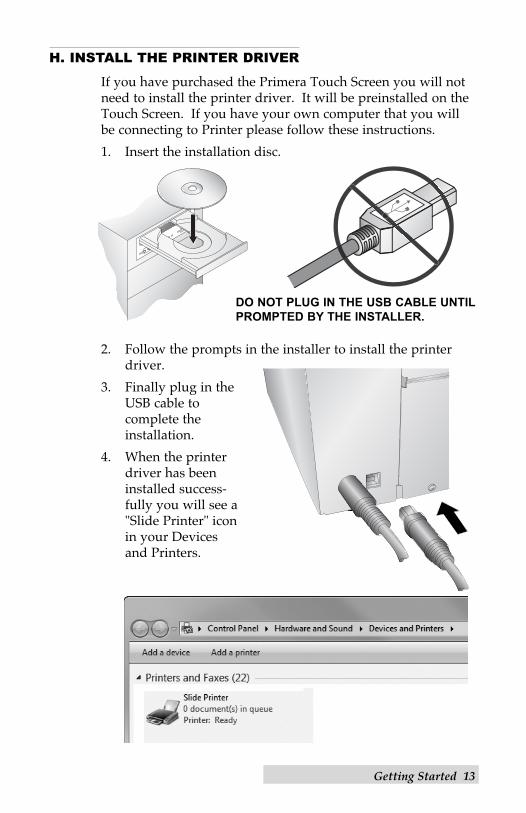
H. INSTALL THE PRINTER DRIVER
If you have purchased the Primera Touch Screen you will notneed to install the printer driver. It will be preinstalled on theTouch Screen. If you have your own computer that you willbe connecting to Printer please follow these instructions.
1. Insert the installation disc.
2. Follow the prompts in the installer to install the printerdriver.
3. Finally plug in theUSB cable to complete the installation.
4. When the printerdriver has beeninstalled success-fully you will see a"Slide Printer" iconin your Devicesand Printers.
DO NOT PLUG IN THE USB CABLE UNTIL
PROMPTED BY THE INSTALLER.
14 Printing Slides
Section 2: Printing Slides
If you have purchased the Primera PTLAB software or thePrimera Touch Screen Computer with the PTLAB software youcan use it to print to the Signature Slide Printer. The PTLabsoftware has its own manual. Please refer to it for detailedcapabilities.
A. PRINTING FROM OTHER PROGRAMS
Printing to the Slide Printer from other software can be accomplished by using the standard Windows driver. The document requirements are listed below:• Default Page = .87" (22mm) W x .67" (17mm) H • Colors = Cyan, Magenta, Yellow, Red, Blue/Purple,
Green, Black• All colors must be 100% saturated To print, simply go the applications print function. Choose the "Slide Printer" as the printer. Click OK to print.
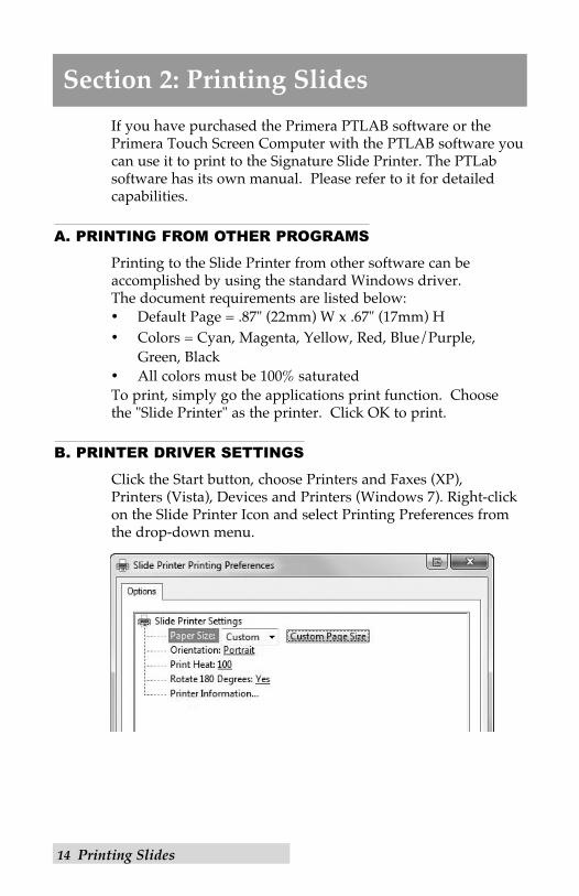
B. PRINTER DRIVER SETTINGS
Click the Start button, choose Printers and Faxes (XP), Printers (Vista), Devices and Printers (Windows 7). Right-clickon the Slide Printer Icon and select Printing Preferences fromthe drop-down menu.

Printing Slides 15
Paper Size: Default paper size is set to the maximum. Editthese settings if you are printing to slides with a smaller print-able area.
Orientation: Change the orientation to Portrait or Landscape.
Print Heat: Increase or decrease the Print Heat from 1-255.Increase to print heat to improve print quality. 100 is thedefault value. Sustained use of a high print heat values willdecrease the life of the print head and potentially break the ribbon. Different manufacturers of slides may require more orless heat. The minimum heat settings possible that result in agood print should be used.
Rotate 180 Degrees: Flips the image up-side down . Defaultsetting is Yes.
Printer Information… Click here to display, printer driver ver-sions, firmware versions, total prints, current status, remainingslides, remaining prints and offset values.
16 Maintenance and Troubleshooting
Section 3: Maintenance and Troubleshooting
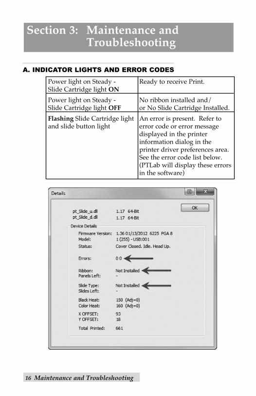
A. INDICATOR LIGHTS AND ERROR CODES
Power light on Steady - Ready to receive Print.Slide Cartridge light ON
Power light on Steady - No ribbon installed and/Slide Cartridge light OFF or No Slide Cartridge Installed.
Flashing Slide Cartridge light An error is present. Refer toand slide button light error code or error message
displayed in the printer information dialog in the printer driver preferences area.See the error code list below. (PTLab will display these errors in the software)
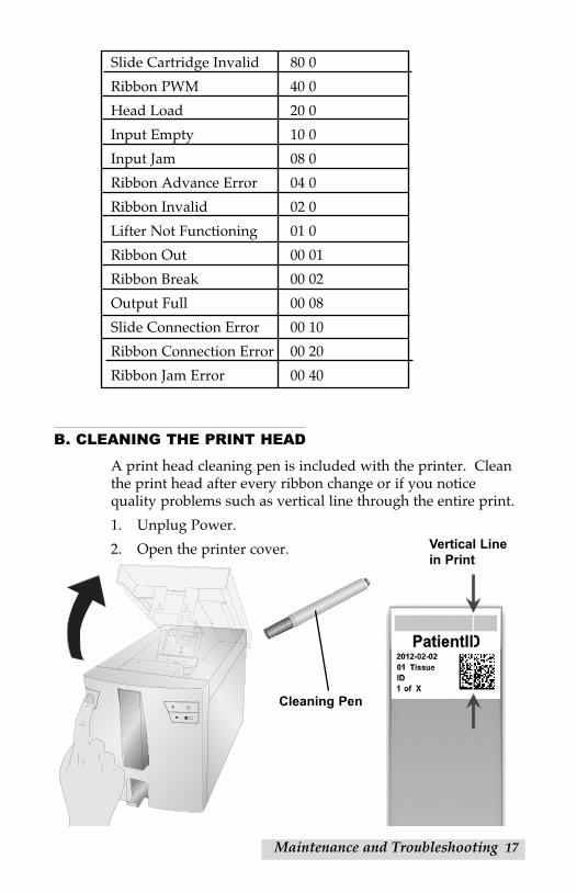
Slide Cartridge Invalid 80 0
Ribbon PWM 40 0
Head Load 20 0
Input Empty 10 0
Input Jam 08 0
Ribbon Advance Error 04 0
Ribbon Invalid 02 0
Lifter Not Functioning 01 0
Ribbon Out 00 01
Ribbon Break 00 02
Output Full 00 08
Slide Connection Error 00 10
Ribbon Connection Error 00 20
Ribbon Jam Error 00 40
B. CLEANING THE PRINT HEAD
A print head cleaning pen is included with the printer. Cleanthe print head after every ribbon change or if you notice quality problems such as vertical line through the entire print.
1. Unplug Power.
2. Open the printer cover.
Maintenance and Troubleshooting 17
Vertical Line
in Print
Cleaning Pen
18 Maintenance and Troubleshooting
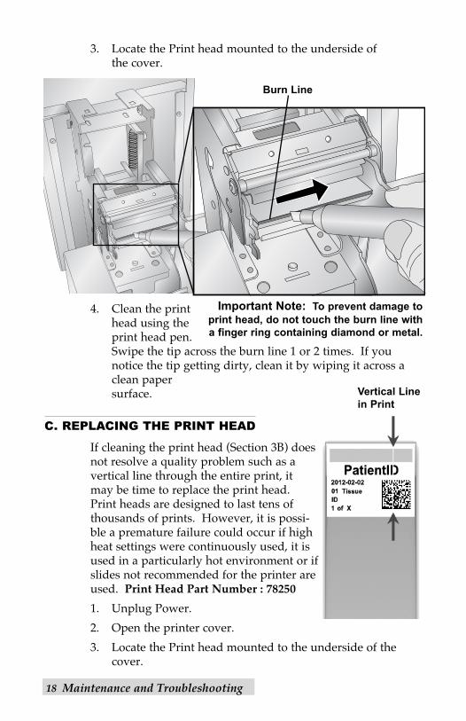
3. Locate the Print head mounted to the underside of the cover.
4. Clean the printhead using theprint head pen.Swipe the tip across the burn line 1 or 2 times. If younotice the tip getting dirty, clean it by wiping it across aclean paper surface.
C. REPLACING THE PRINT HEAD
If cleaning the print head (Section 3B) doesnot resolve a quality problem such as avertical line through the entire print, it may be time to replace the print head.Print heads are designed to last tens ofthousands of prints. However, it is possi-ble a premature failure could occur if highheat settings were continuously used, it isused in a particularly hot environment or ifslides not recommended for the printer areused. Print Head Part Number : 78250
1. Unplug Power.
2. Open the printer cover.
3. Locate the Print head mounted to the underside of thecover.
Vertical Line
in Print
Important Note: To prevent damage to
print head, do not touch the burn line with
a finger ring containing diamond or metal.
Burn Line
Maintenance and Troubleshooting 19
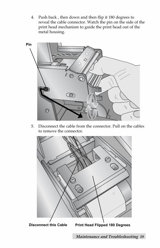
4. Push back , then down and then flip it 180 degrees toreveal the cable connector. Watch the pin on the side of theprint head mechanism to guide the print head out of themetal housing.
5. Disconnect the cable from the connector. Pull on the cablesto remove the connector.
Pin
Print Head Flipped 180 DegreesDisconnect this Cable
20 Maintenance and Troubleshooting
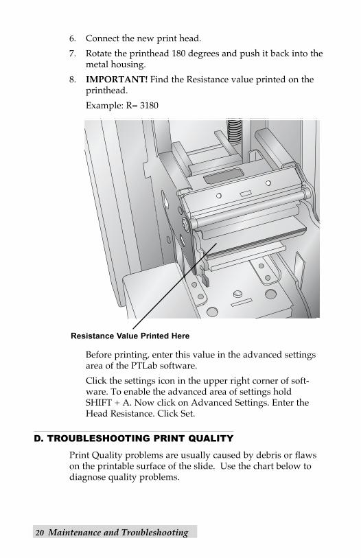
6. Connect the new print head.
7. Rotate the printhead 180 degrees and push it back into themetal housing.
8. IMPORTANT! Find the Resistance value printed on theprinthead.
Example: R= 3180
Before printing, enter this value in the advanced settingsarea of the PTLab software.
Click the settings icon in the upper right corner of soft-ware. To enable the advanced area of settings hold SHIFT + A. Now click on Advanced Settings. Enter theHead Resistance. Click Set.
D. TROUBLESHOOTING PRINT QUALITY
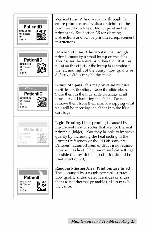
Print Quality problems are usually caused by debris or flawson the printable surface of the slide. Use the chart below todiagnose quality problems.
Resistance Value Printed Here
Maintenance and Troubleshooting 21
Vertical Line. A line vertically through theentire print is cause by dust or debris on theprint head burn line or blown pixel on the print head. See Section 3B for cleaninginstructions and 3C for print head replacementinstructions.
Horizontal Line. A horizontal line throughprint is cause by a small bump on the slide.This causes the entire print head to lift at thispoint so the effect of the bump is extended tothe left and right of the bump. Low quality ordefective slides may be the cause.
Group of Spots. This may by cause by dustparticles on the slide. Keep the slide clean.Store them in the blue slide cartridge at alltimes. Avoid handling the slides. Do notremove them from their shrink wrapping untilyou will be inserting the slides into the bluecartridge.
Light Printing. Light printing is caused byinsufficient heat or slides that are not thermalprintable (inkjet). You may be able to improvequality by increasing the heat setting in thePrinter Preferences or the PTLab software.Different manufacturers of slides may requiremore or less heat. The minimum heat settingspossible that result in a good print should beused. (Section 2B)
Random Missing Area (Print Surface Intact).This is caused by a rough printable surface.Low quality slides, defective slides or slidesthat are not thermal printable (inkjet) may bethe cause.
22 Maintenance and Troubleshooting
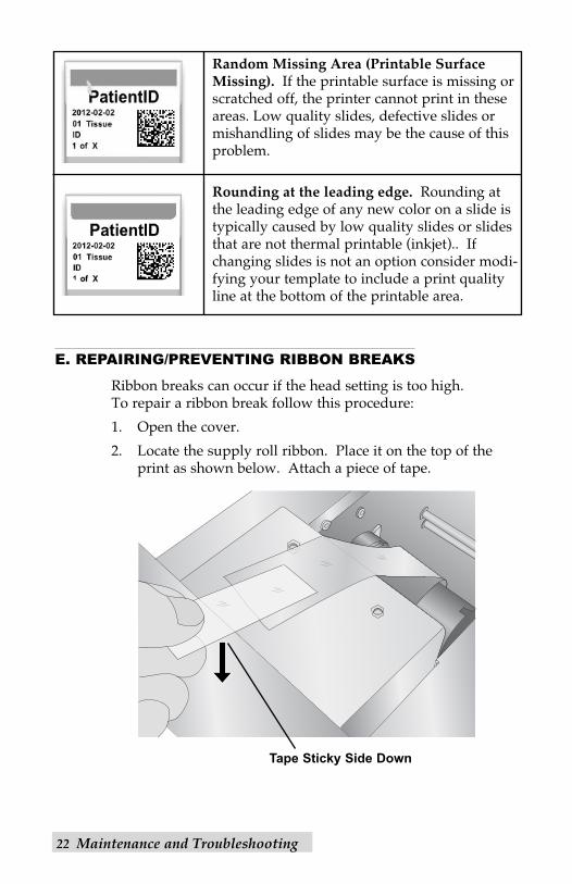
Random Missing Area (Printable SurfaceMissing). If the printable surface is missing orscratched off, the printer cannot print in theseareas. Low quality slides, defective slides ormishandling of slides may be the cause of thisproblem.
Rounding at the leading edge. Rounding atthe leading edge of any new color on a slide istypically caused by low quality slides or slidesthat are not thermal printable (inkjet).. Ifchanging slides is not an option consider modi-fying your template to include a print qualityline at the bottom of the printable area.
E. REPAIRING/PREVENTING RIBBON BREAKS
Ribbon breaks can occur if the head setting is too high. To repair a ribbon break follow this procedure:
1. Open the cover.
2. Locate the supply roll ribbon. Place it on the top of theprint as shown below. Attach a piece of tape.
Tape Sticky Side Down
Maintenance and Troubleshooting 23
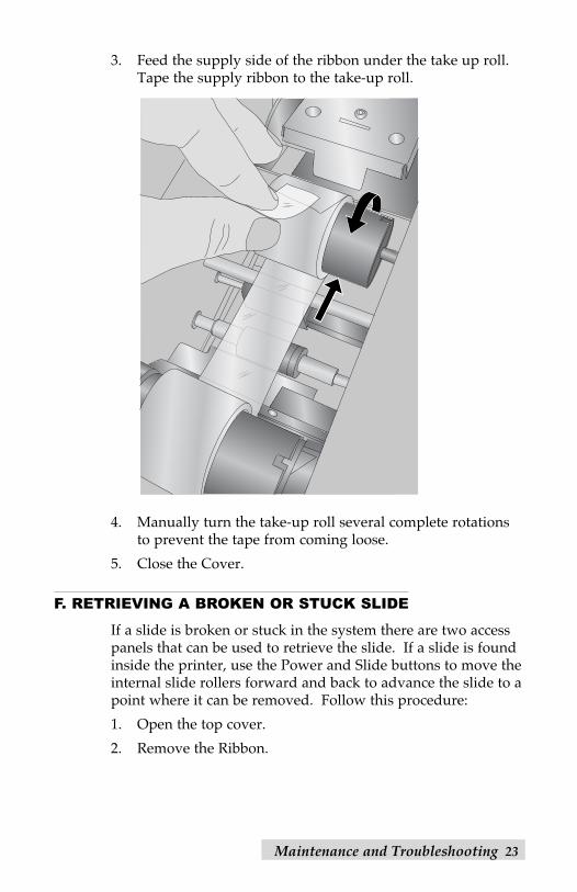
3. Feed the supply side of the ribbon under the take up roll.Tape the supply ribbon to the take-up roll.
4. Manually turn the take-up roll several complete rotationsto prevent the tape from coming loose.
5. Close the Cover.
F. RETRIEVING A BROKEN OR STUCK SLIDE
If a slide is broken or stuck in the system there are two accesspanels that can be used to retrieve the slide. If a slide is foundinside the printer, use the Power and Slide buttons to move theinternal slide rollers forward and back to advance the slide to apoint where it can be removed. Follow this procedure:
1. Open the top cover.
2. Remove the Ribbon.

24 Maintenance and Troubleshooting
3. Remove the slide cartridge.
4. In the slide cartridge compartment check near the bottomroller for a slide.
5. Check under the ribbon. Use the Power and Slide buttonsto move the slide to a position where you can remove it.
Tip! Once the slide is on the rubber belts near the back, youcan close the cover and press the slide button to advancethe side down the slide chute.
6. If the slide is near the back and you are unable to retrieveit using the buttons you can remove the back cover panel.
Screws for Access Panel
Maintenance and Troubleshooting 25
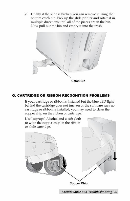
7. Finally if the slide is broken you can remove it using thebottom catch bin. Pick up the slide printer and rotate it inmultiple directions until all of the pieces are in the bin.Now pull out the bin and empty it into the trash.
G. CARTRIDGE OR RIBBON RECOGNITION PROBLEMS
If your cartridge or ribbon is installed but the blue LED lightbehind the cartridge does not turn on or the software says nocartridge or ribbon is installed, you may need to clean the copper chip on the ribbon or cartridge.
Use Isopropal Alcohol and a soft clothto wipe the copper chip on the ribbonor slide cartridge.
Catch Bin
Copper Chip

26 Maintenance and Troubleshooting
H. TECHNICAL SUPPORT
If you have difficulties in operating your Printer, contact thetechnical support number using one of the methods listedbelow.
Source Location
Primera Knowledge Base www.primerahealthcare.com/knowledgebase.html
Email Support [email protected]
Technical Specifications 27
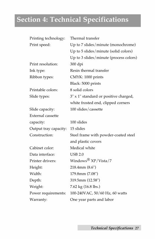
Section 4: Technical Specifications
Printing technology: Thermal transfer
Print speed: Up to 7 slides/minute (monochrome)
Up to 5 slides/minute (solid colors)
Up to 3 slides/minute (process colors)
Print resolution: 300 dpi
Ink type: Resin thermal transfer
Ribbon types: CMYK: 1000 prints
Black: 5000 prints
Printable colors: 8 solid colors
Slide types: 3" x 1" standard or positive charged,
white frosted end, clipped corners
Slide capacity: 100 slides/cassette
External cassette
capacity: 100 slides
Output tray capacity: 15 slides
Construction: Steel frame with powder-coated steel
and plastic covers
Cabinet color: Medical white
Data interface: USB 2.0
Printer drivers: Windows® XP/Vista/7
Height: 218.4mm (8.6")
Width: 179.8mm (7.08")
Depth: 319.5mm (12.58")
Weight: 7.62 kg (16.8 lbs.)
Power requirements: 100-240VAC, 50/60 Hz, 60 watts
Warranty: One year parts and labor