Embed Size (px)
Citation preview


9/1/2011
1
By
Swapan Kumar MondalIES Officer (Railway)NTPC Ltd (5 Years)
Teaching Experience ( 12 Years)GATE percentile 99.96
Analysis of Previous IES PapersProduction Materials Total Question
IES-2011 31 28 59
IES-2010 33 19 52
IES-2009 38 16 54IES 2009 38 16 54
IES-2008 25 15 40
IES-2007 34 15 49
IES-2006 23 13 36
IES-2005 28 12 40
Average 30 17 47
No of questions asked
Analysis of Previous GATE PapersProduction Materials Total Marks
GATE-2011 13 1 14 out of 100
GATE-2010 13 1 14 out of 100
GATE-2009 16 2 18 out of 100GATE 2009 16 2 18 out of 100
GATE-2008 26 0 26 out of 150
GATE-2007 25 2 27 out of 150
GATE-2006 25 1 26 out of 150
GATE-2005 19 1 26 out of 150
Average 15.22 % 0.9 % 16.57 %
No of Marks asked
Why PPT and Video needed ?
Discussed Questions are available atwww.scribd.comE‐mail: [email protected]: reliancejainPassword: reliancejain
Then open "My Document“ and download desired file.
9/1/2011
1
Theory of Metal Cutting
By S K Mondal
Classification of Manufacturing Process
Shaping or forming
Joining process
Removal process
Regenerative manufacturing
Regenerative Manufacturing
Production of solid products in layer by layer from
raw materials in different forms.
Very rapid, accurate used for Rapid prototyping
and tooling.
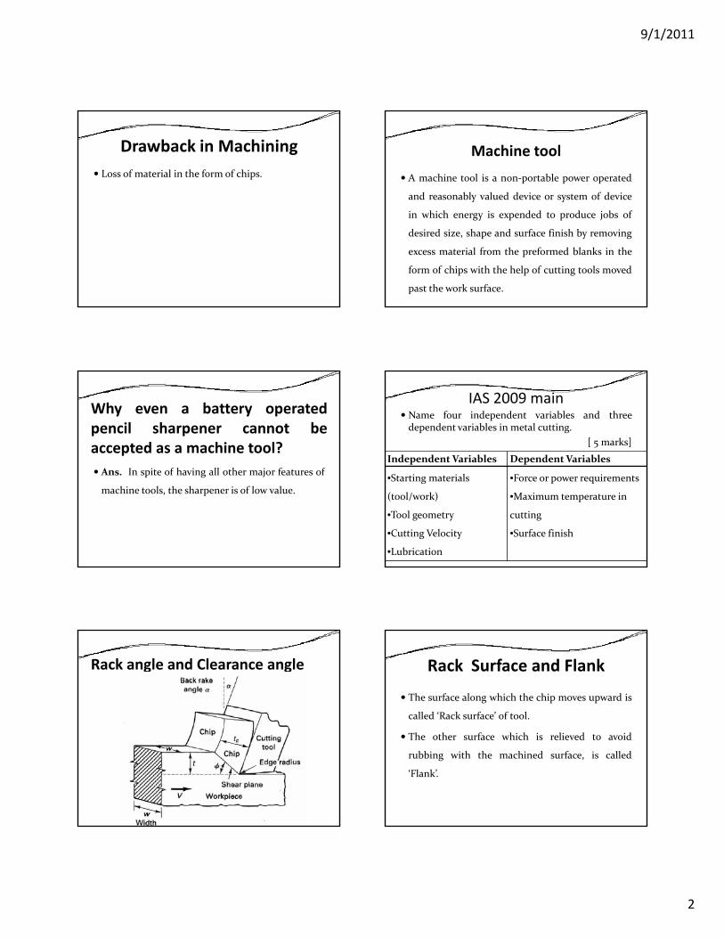
Basic Principle of Regenerative Manufacturing
Advantages:•Process is Independent of Part Feature•No Blanks are Requires•Toolless process•Easily Automation Possible
MachiningMachining is an essential process of finishing by
which jobs are produced to the desired dimensions
and surface finish by gradually removing they g y g
excess material from the preformed blank in the
form of chips with the help of cutting tools moved
past the work surface. Machining is a removal
process.
Machining aim toFulfill its functional requirements
Improve its performance
Prolong its service.
9/1/2011
2
Drawback in MachiningLoss of material in the form of chips.
Machine toolA machine tool is a non‐portable power operated
and reasonably valued device or system of device
in which energy is expended to produce jobs of
desired size, shape and surface finish by removing
excess material from the preformed blanks in the
form of chips with the help of cutting tools moved
past the work surface.
Why even a battery operatedpencil sharpener cannot beaccepted as a machine tool?
A I i f h i ll h j f fAns. In spite of having all other major features of
machine tools, the sharpener is of low value.
IAS 2009 mainName four independent variables and threedependent variables in metal cutting.
[ 5 marks]
Independent Variables Dependent Variables
•Starting materials
(tool/work)
•Tool geometry
•Cutting Velocity
•Lubrication
•Force or power requirements
•Maximum temperature in
cutting
•Surface finish
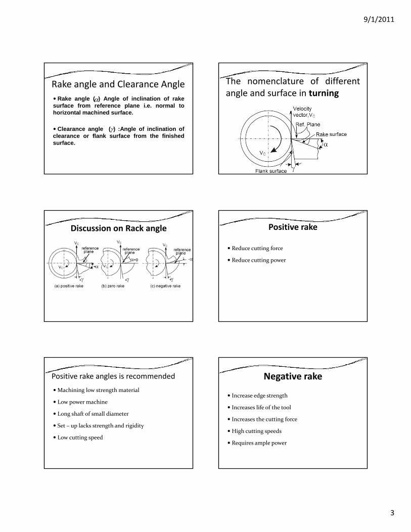
Rack angle and Clearance angle Rack Surface and Flank
The surface along which the chip moves upward is
called ‘Rack surface’ of tool.
The other surface which is relieved to avoid
rubbing with the machined surface, is called
‘Flank’.
9/1/2011
3
Rake angle and Clearance AngleRake angle ( ) Angle of inclination of rake
surface from reference plane i.e. normal tohorizontal machined surface.
α
Clearance angle ( ) :Angle of inclination ofclearance or flank surface from the finishedsurface.
γ
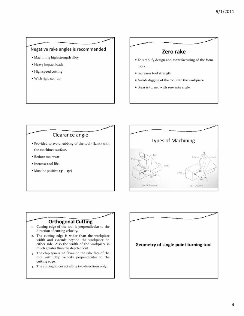
The nomenclature of differentangle and surface in turning
Discussion on Rack angle Positive rake
Reduce cutting force
Reduce cutting power
Positive rake angles is recommended
Machining low strength material
Low power machine
Long shaft of small diameterLong shaft of small diameter
Set – up lacks strength and rigidity
Low cutting speed
Negative rake
Increase edge strength
Increases life of the tool
Increases the cutting force
High cutting speeds
Requires ample power
9/1/2011
4
Negative rake angles is recommended
Machining high strength alloy
Heavy impact loads
Hi h d iHigh speed cutting
With rigid set‐ up
Zero rakeTo simplify design and manufacturing of the form
tools.
Increases tool strength
Avoids digging of the tool into the workpiece
Brass is turned with zero rake angle
Clearance angleProvided to avoid rubbing of the tool (flank) with
the machined surface.
Reduce tool wear
Increase tool life.
Must be positive (30 – 150)
Types of Machining
Orthogonal Cutting1. Cutting edge of the tool is perpendicular to the
direction of cutting velocity.2. The cutting edge is wider than the workpiece
width and extends beyond the workpiece oneither side. Also the width of the workpiece ispmuch greater than the depth of cut.
3. The chip generated flows on the rake face of thetool with chip velocity perpendicular to thecutting edge.
4. The cutting forces act along two directions only.
Geometry of single point turning toolGeometry of single point turning tool
9/1/2011
5
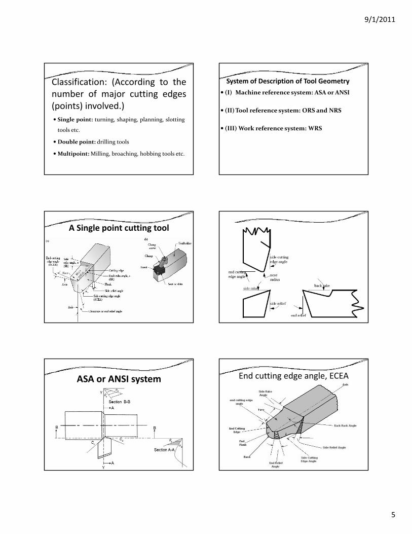
Classification: (According to thenumber of major cutting edges(points) involved.)
Single point: turning shaping planning slottingSingle point: turning, shaping, planning, slotting
tools etc.
Double point: drilling tools
Multipoint:Milling, broaching, hobbing tools etc.
System of Description of Tool Geometry(I) Machine reference system: ASA or ANSI
(II)Tool reference system: ORS and NRS
(III) Work reference system: WRS
A Single point cutting tool
ASA or ANSI system End cutting edge angle, ECEA
9/1/2011
6
Back Rake angleIt is the angle between the face of the tool and the
base of the shank or holder, and is usually
measured in a plane through the side‐cutting edge,
and at right angles to the base
It affects the ability of the tool to shear the work
material and form the chip.
Side‐rake angle (axial rake)It is the angle between the face of the tool and the baseof the shank or holder, and is usually measured in aplane perpendicular to the base, to the side‐cuttingedgeI i th id k l d th hiIncrease in the side rake angle reduces the chipthickness in turning.
Side‐relief angleIt is the angle between the portion of the side flank
immediately below the side‐cutting edge, and a
line drawn through this cutting edge
perpendicular to the base.
It is measured in a plane perpendicular to the side
flank.
End‐relief angleIt is the angle between the portion of the end flank
immediately below the end cutting edge, and a line
drawn through this cutting edge perpendicular to
the base. It is usually measured in a plane
perpendicular to the end flank.
The End Relief Angle prevents friction on the flank
of the tool.
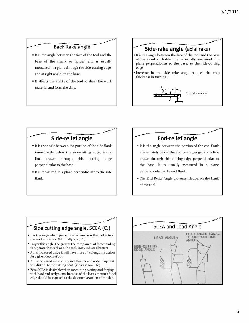
Side cutting edge angle, SCEA (CS)It is the angle which prevents interference as the tool enters the work materials. (Normally 15 – 30o )Larger this angle, the greater the component of force tending to separate the work and the tool. (May induce Chatter)At its increased value it will have more of its length in action for a given depth of cut.At its increased value it produce thinner and wider chip that will distribute the cutting heat. (increase tool life)Zero SCEA is desirable when machining casting and forging with hard and scaly skins, because of the least amount of tool edge should be exposed to the destructive action of the skin.
SCEA and Lead Angle
9/1/2011
7
Lip angleLip angle or cutting angle depends on the on therake and clearance angle provided on the tool anddetermine the strength of the cutting edge.
l l l h f h dA larger lip angle permits machining of hardermetals, allow heavier depth of cut, increase toollife, better heat dissipation.Larger lip angle reduce cutting speed(Disadvantage)
Nose radiusIt is curvature of the tool tip.
It provides strengthening of the tool nose and better
surface finish.
But too large a nose radius will induce chatter.
If nose radius increased cutting force and cutting power
increased.
Tool designation (ANSI) or ASATo remember easily follow the rule
rake, relief, cutting edge
Side will come last
finish with nose radius (inch)
b s e s e sC C Rα α θ θ− − − − − −
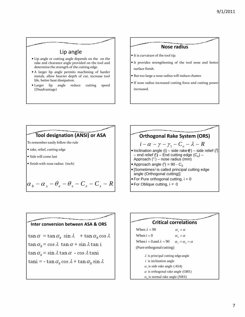
Orthogonal Rake System (ORS)
Inclination angle (i) – side rake ( ) – side relief ( ) – end relief ( ) – End cutting edge (Ce) –Approach ( ) nose radius (mm)
1 ei C Rα γ γ λ− − − − − −α γ
1γλApproach ( ) – nose radius (mm)
Approach angle ( ) = 90 - CS[Sometimes is called principal cutting edge angle (Orthogonal cutting)]For Pure orthogonal cutting, i = 0For Oblique cutting, i 0
λ
λ
λ
≠
Inter conversion between ASA & ORS Critical correlationsWhen 90When 0When 0and 90(P h l i )
s
n
s n
ii
λ α αα α
λ α α α
= =
= == = = =
(Pureorthogonalcutting)
is principal cutting edgeangle is inclination angleis side rake angle ( )is orthogonal rake angle ( )is normal rake angle (NRS)
s
n
iASA
ORS
λ
ααα
9/1/2011
8
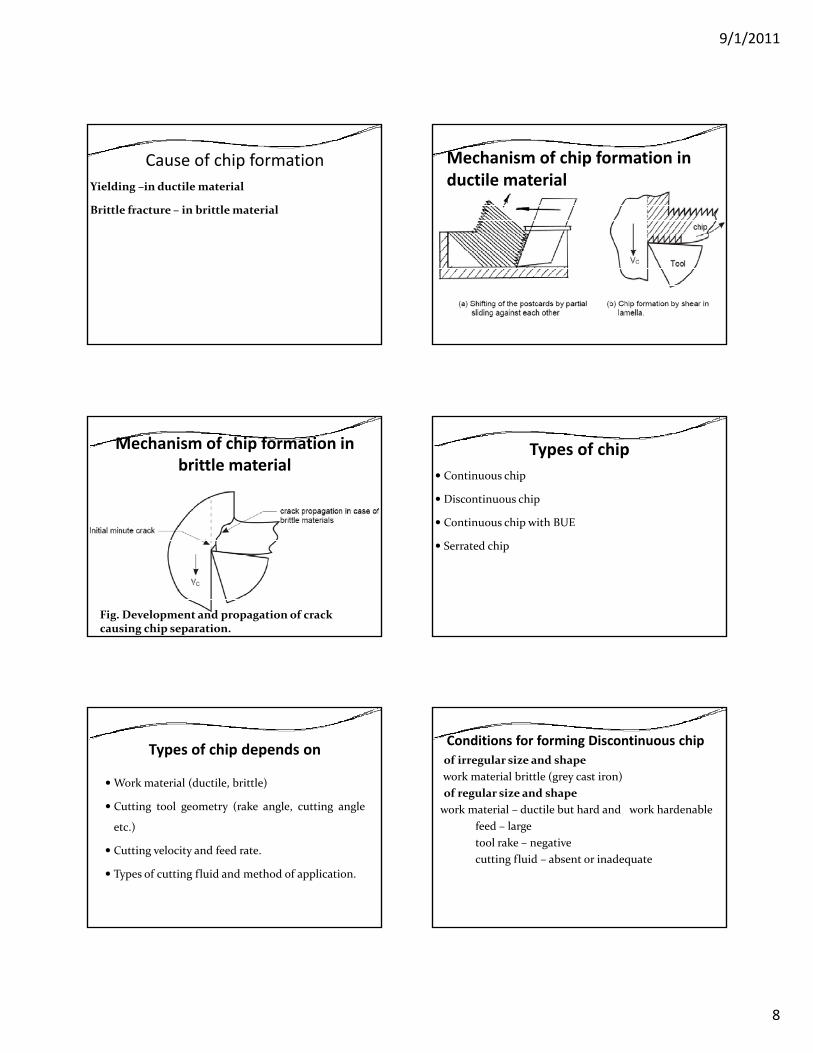
Cause of chip formationYielding –in ductile material
Brittle fracture – in brittle material
Mechanism of chip formation in ductile material
Mechanism of chip formation in brittle material
Fig. Development and propagation of crack causing chip separation.
Types of chipContinuous chip
Discontinuous chip
Continuous chip with BUECo t uous c p t U
Serrated chip
Types of chip depends on
Work material (ductile, brittle)
Cutting tool geometry (rake angle, cutting angle
etc.)
Cutting velocity and feed rate.
Types of cutting fluid and method of application.
Conditions for forming Discontinuous chipof irregular size and shape work material brittle (grey cast iron)of regular size and shapework material – ductile but hard and work hardenable
feed – largetool rake – negativecutting fluid – absent or inadequate
9/1/2011
9
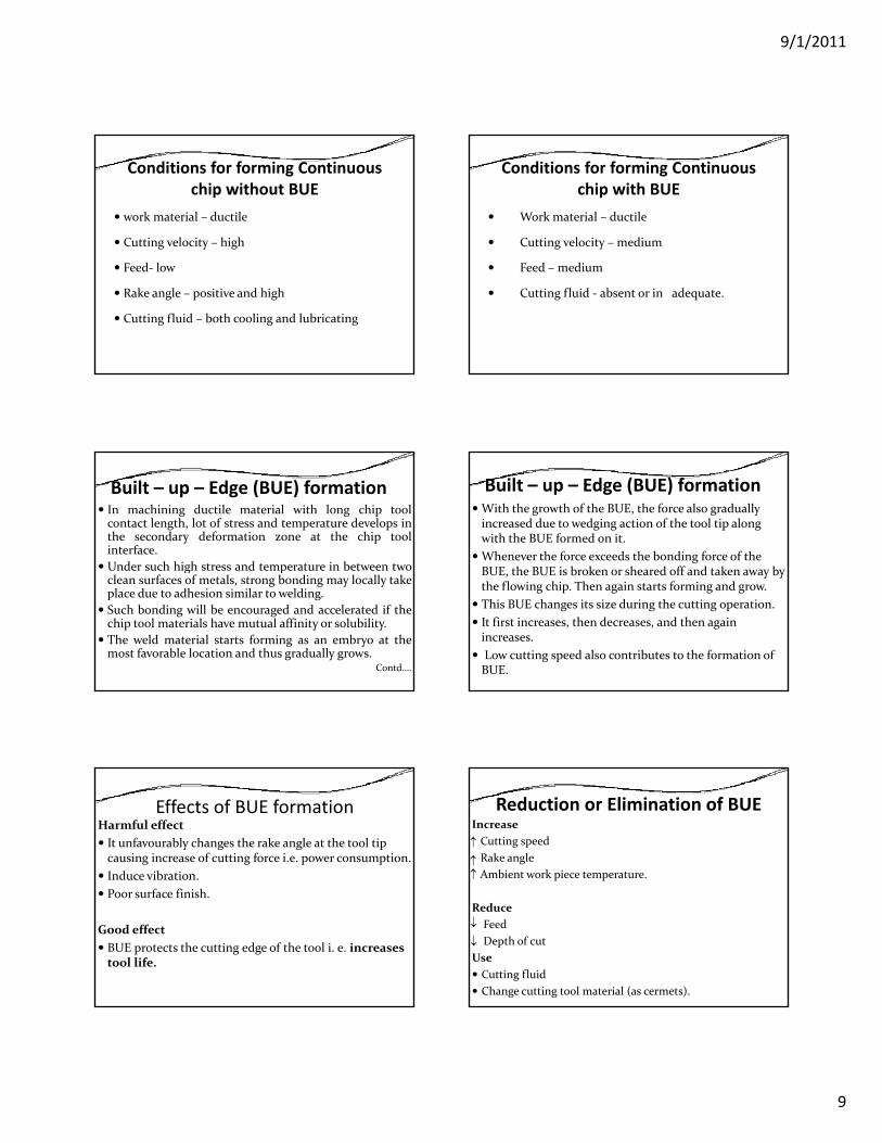
Conditions for forming Continuous chip without BUE
work material – ductile
Cutting velocity – high
Feed‐ low
Rake angle – positive and high
Cutting fluid – both cooling and lubricating
Conditions for forming Continuous chip with BUE
Work material – ductile
Cutting velocity – medium
Feed – medium
Cutting fluid ‐ absent or in adequate.
Built – up – Edge (BUE) formationIn machining ductile material with long chip toolcontact length, lot of stress and temperature develops inthe secondary deformation zone at the chip toolinterface.Under such high stress and temperature in between twog pclean surfaces of metals, strong bonding may locally takeplace due to adhesion similar to welding.Such bonding will be encouraged and accelerated if thechip tool materials have mutual affinity or solubility.The weld material starts forming as an embryo at themost favorable location and thus gradually grows.
Contd….
Built – up – Edge (BUE) formationWith the growth of the BUE, the force also gradually increased due to wedging action of the tool tip along with the BUE formed on it. Whenever the force exceeds the bonding force of the BUE the BUE is broken or sheared off and taken away by BUE, the BUE is broken or sheared off and taken away by the flowing chip. Then again starts forming and grow. This BUE changes its size during the cutting operation. It first increases, then decreases, and then again increases.Low cutting speed also contributes to the formation of BUE.
Effects of BUE formationHarmful effectIt unfavourably changes the rake angle at the tool tip causing increase of cutting force i.e. power consumption.Induce vibration.Poor surface finish.
Good effectBUE protects the cutting edge of the tool i. e. increases tool life.
Reduction or Elimination of BUEIncreaseCutting speedRake angleAmbient work piece temperature.
↑
↑↑
Reduce FeedDepth of cut
UseCutting fluidChange cutting tool material (as cermets).
↓
↓
9/1/2011
10
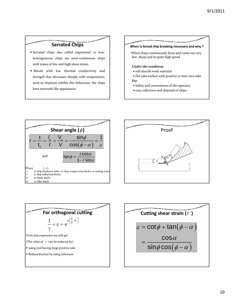
Serrated ChipsSerrated chips also called segmented or non‐
homogeneous chips are semi‐continuous chips
with zones of low and high shear strain.
Metals with low thermal conductivity and
strength that decreases sharply with temperature,
such as titanium exhibit this behaviour, the chips
have sawtooth like appearance.
When is forced chip breaking necessary and why ?
When chips continuously form and come out very hot, sharp and at quite high speed
Under the conditionUnder the conditionsoft ductile work materialflat rake surface with positive or near zero rake
ForSafety and convenience of the operatoreasy collection and disposal of chips
Shear angle ( )
( )c c
c
Vt sin 1t V cos
lrl
φφ α ε
= = = = =−
φ
r costan1 sinr
αφα
=−
and
Proof
For orthogonal cutting
From this expression we will get
21 eπ⎛ ⎞μ −α⎜ ⎟
⎝ ⎠= ε =γ
From this expression we will get
(The value of can be reduced by)
using tool having large positive rake
Reduce friction by using lubricant.
ε
Cutting shear strain ( )ε
( )cot tanε φ φ α= + −
( )cos
sin cosα
φ φ α=
−
9/1/2011
11
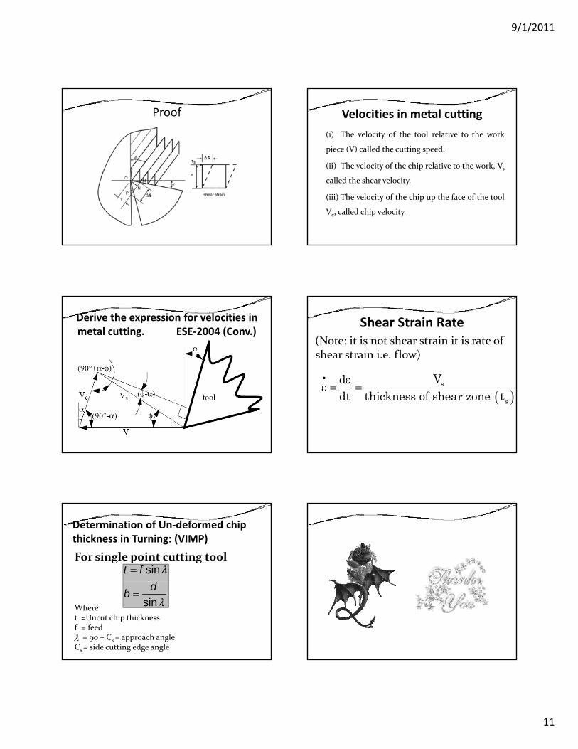
Proof Velocities in metal cutting(i) The velocity of the tool relative to the work
piece (V) called the cutting speed.
(ii) The velocity of the chip relative to the work V(ii) The velocity of the chip relative to the work, Vs
called the shear velocity.
(iii) The velocity of the chip up the face of the tool
Vc, called chip velocity.
Derive the expression for velocities in metal cutting. ESE‐2004 (Conv.)
Shear Strain Rate(Note: it is not shear strain it is rate of shear strain i.e. flow)
( )s
s
Vddt thickness of shear zone t
• εε = =
Determination of Un‐deformed chip thickness in Turning: (VIMP)For single point cutting tool
sint f λ=
Wheret =Uncut chip thicknessf = feed
= 90 – Cs = approach angleCs = side cutting edge angle
sindbλ
=
λ
9/1/2011
1
Force & Power in Metal Cutting
By S K Mondal
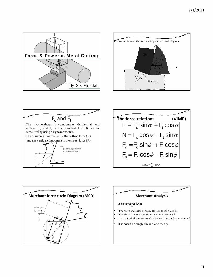
When a cut is made the forces acting on the metal chips are:
Fc and FtThe two orthogonal components (horizontal andvertical) Fc and Ft of the resultant force R can bemeasured by using a dynamometer.The horizontal component is the cutting force (Fc)and the vertical component is the thrust force (Ft)
The force relations (VIMP)
c t
c t
F = F sin F cosN F cos F sin
α αα α+
= −c t
n c t
s c t
F F sin F cosF F cos F sin
φ φφ φ
= +
= −=
Fand = tanN
μ β
Merchant force circle Diagram (MCD)
( )β α−
Merchant Analysis
Assumption
• It is based on single shear plane theory.

9/1/2011
2
Limitations of Merchant’s Theory1. Merchant theory is valid only for orthogonal cutting.2. By the ratio F/N, the Merchant theory gives apparent
(not actual) co‐efficient of friction.
From Merchant Force Circle Diagram
=π α βφ + −4 2 2
φ +
Modified Merchant Theory
( )
τ = τ + σ σ
⎡ ⎤σ =⎢ ⎥
⎣ ⎦φ β
s so s s
ns
s
1
k where, is the normal stress on shear plane.FA
d h 2 k( )−φ β α 1and then 2 + - =cot k
Theory of Lee and Shaffer
πφ + α −β
They applied the theory of plasticity for an ideal-rigid-plastic material.They also assumed that deformation occured on a thin-shear plane.
They derive.
=44
Other RelationsBy Stabler
By dimensional analysis
where, k, a, b, k1, a1 and b1 are empirical constants to beestablished from the experimental dataf is feed and d is depth of cut.
Compare turning with orthogonal cutting

9/1/2011
3
Fc: primary cutting force acting in the direction ofthe cutting velocity, largest force and accounts for99% of the power required by the process.Ff: feed force acting in the direction of the tool feed.This force is about 50% of Fc, but accounts for only asmall percentage of the power required because feedsmall percentage of the power required because feedrates are usually small compared to cutting speeds.Fr: radial or thrust force acting perpendicular to themachined surface. This force is about 50% of Ff andcontributes very little to power requirementsbecause velocity in the radial direction is negligible.
Metal Removal Rate (MRR)
Metal removal rate (MRR) = Ac.V= b t V
hWhereAc = cross‐section area of uncut chipV = cutting speed = DN
60π
Power Consumed During Cutting
×cF VcF VWhereFc= cutting force
V = cutting speed = DN60π
Friction in Metal Cutting
Heat and Temperature in Metal Cutting Determination of cutting temperature
Analytically – using mathematical models (equations) ifavailable or can be developed. This method is simple,quick and inexpensive but less accurate and precise.
Experimentally – this method is more accurate, preciseand reliable.
9/1/2011
4
Experimental Methods are Calorimetric method
Decolourising agent
Tool‐work thermocouple
Moving thermocouple techniqueMoving thermocouple technique
Embedded thermocouple technique
Using compound tool
Indirectly from Hardness and structural transformation
Photo‐cell technique
Infra ray detection method
Dynamometers for measuring cutting forces
Measurement of cutting force(s) is based on three basicprinciples :(a) measurement of elastic deflection of a bodysubjected to the cutting force(b) t f l ti d f ti i t i(b) measurement of elastic deformation, i.e. straininduced by the force(c) measurement of pressure developed in a medium bythe force.
Design requirements for Tool – force Dynamometers
SensitivityThe dynamometer should be reasonably sensitive forprecision measurement
RigidityRigidityThe dynamometer need to be quite rigid to withstand theforces without causing much deflection which may affect themachining condition
Cross sensitivityThe dynamometer should be free from cross sensitivity suchthat one force (say PZ) does not affect measurement of theother forces (say PX and PY)
Types of Dynamometers The dynamometers being commonly used now‐a‐daysfor measuring machining forces desirably accurately andprecisely (both static and dynamic characteristics) areEither
Strain gauge typeStrain gauge typeOr
piezoelectric typeStrain gauge type dynamometers are inexpensive but lessaccurate and consistent, whereas, the piezoelectric typeare highly accurate, reliable and consistent but veryexpensive for high material cost and stringentconstruction.
Strain Gauge Dynamometers
The strain, ε induced by the force changes the electricalresistance, R, of the strain gauges which are firmlypasted on the surface of the tool‐holding beam as
R GεΔ=
where, G = gauge factor (around 2.0 for conductivegauges)The change in resistance of the gauges connected in awheatstone bridge produces voltage output ΔV, througha strain measuring bridge (SMB)
R


![Xy;lo {o,Sy yíwko d…yto b [;˜,o mh;nvedicreserve.mum.edu/mahabharata/mahabharata15_ashramavasa.pdf · ¨p;ste Sm t ' v Oı ' htp u]' jn;…/pm ( 10 Xy;lo {o,Sy yíwko d…yto](https://img.pdfslide.us/doc/110x75/5be574bf09d3f288458bb0bc/xylo-osy-yiwko-dyto-b-o-mh-pste-sm-t-v-oi-htp-u-jnpm-.jpg)


![AKANE #C6 Unrequited the Devil_s Heart [Yto&Nikkita]](https://img.pdfslide.us/doc/110x75/577c84431a28abe054b82e54/akane-c6-unrequited-the-devils-heart-ytonikkita.jpg)