Embed Size (px)
Citation preview
1 5 05-12
SUBJECT DATE
Cylinder Head May 2012
Additions, Revisions, or Updates
Publication Number / Title Platform Section Title Change
DDC-SVC-MAN-0023EPA04 MBE
4000
Cylinder Head
Changed the warpage spec to 0.1mm (0.004 in.)
Additional Information
DDC-SVC-MAN-0026EPA07 MBE
4000
Cylinder Head
Additional EngineInformation
5 05-12
All information subject to change without notice. 35 05-12 Copyright © 2012 DETROIT DIESEL CORPORATION

The following applies to DDC-SVC-MAN-0023:
CYLINDER HEAD
The MBE 4000 engine has individual heads for each cylinder. To remove one head, follow theseinstructions, step by step. To remove all the heads, repeat each step in these instructions, as applicable,for all six cylinders.
CYLINDER HEAD REMOVAL
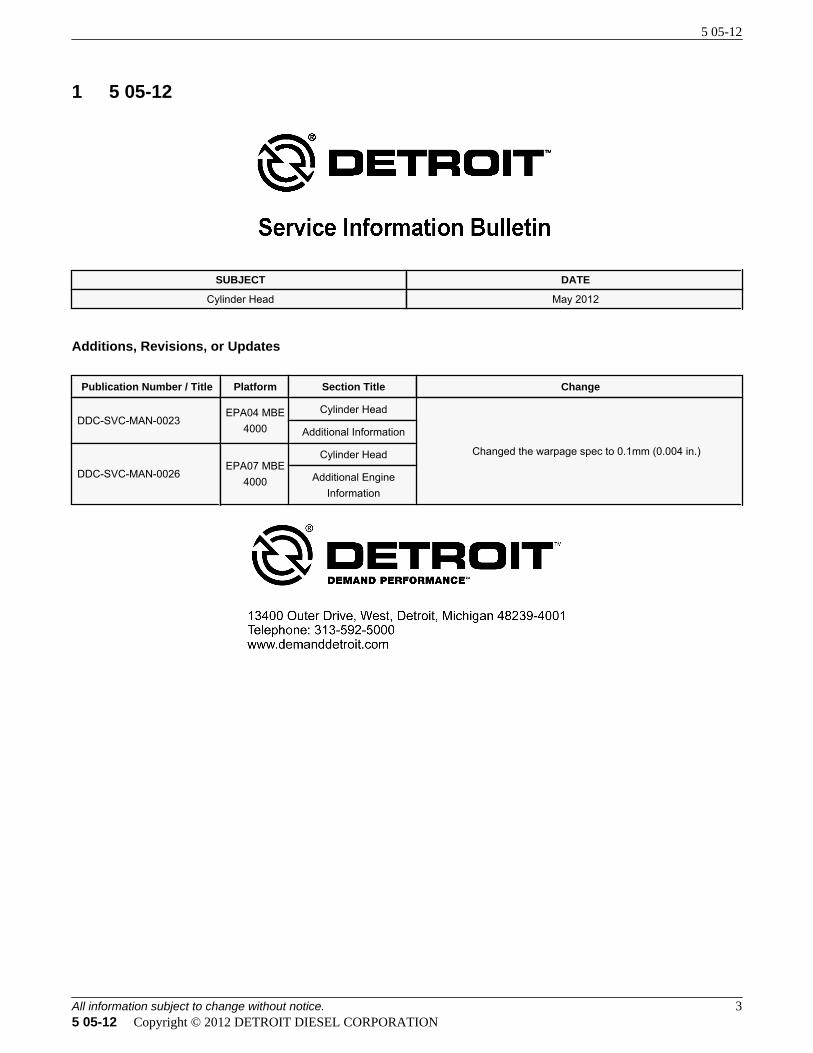
Remove the cylinder head as follows: See Figure 1 for an exploded view of a cylinder head.
1. High-Pressure Fuel Line 6. Coolant Line 11. Cylinder Head Gasket
2. Pushrod 7. Cylinder Head Bolt 12. Exhaust Manifold
3. Cylinder Head 8. Constant-Throttle Line 13. Exhaust Manifold Mounting Bolt
4. Seal Ring 9. Spacer 14. Guide Pin
5. Hollow Core (Banjo) Bolt 10. Exhaust Port Gasket
Figure 1 Exploded View of Cylinder Head
HOT COOLANT
To avoid scalding from the expulsion of hot coolant, neverremove the cooling system pressure cap while the engine isat operating temperature. Wear adequate protective clothing(face shield, rubber gloves, apron, and boots). Remove thecap slowly to relieve pressure.
1. Drain the coolant from the radiator.
NOTE:Clean the cylinder head cover before removing it.
2. Remove the cylinder head cover. Refer to section .
3. Remove the rocker arm assembly. Mark the valve bridges and pushrods in order of removal.Refer to section .
4. Remove the engine trim covers to gain access to the high-pressure fuel lines.
5. Remove the charge-air intake manifold.
PERSONAL INJURY
To prevent the escape of high pressure fuel that can penetrateskin, ensure the engine has been shut down for a minimum of10 minutes before servicing any component within the highpressure circuit. Residual high fuel pressure may be presentwithin the circuit.
NOTICE:
Do not move the thrust bolt (3) during the removal of thehigh-pressure fuel line, because there is danger of causing achange in the position of the transfer-tube. If the position of thetransfer-tube is changed, engine damage could result.
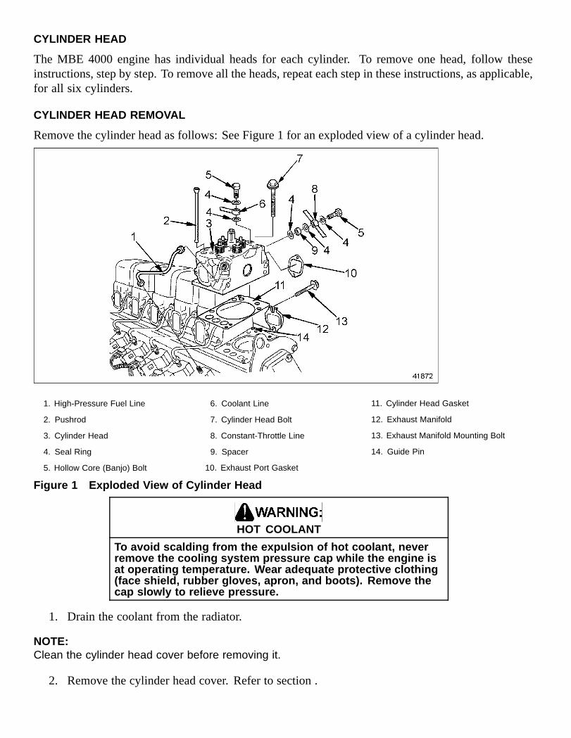
6. Using two wrenches, loosen the high-pressure fuel line (2) at the transfer-tube fitting (4). SeeFigure 2.
1. Pump-End Fitting 3. Thrust Bolt
2. High-Pressure Injector Line 4. Transfer-Tube Fitting
Figure 2 High-Pressure Fuel Line Fittings
[a] Using a paint pen, mark the location of the thrust bolt.
[b] Place one wrench on the thrust bolt to secure the transfer-tube. Place the other wrenchon the high-pressure line fitting.
[c] Turn the wrench on the high-pressure line fitting while holding the other wrench on thethrust bolt.
7. Remove the high-pressure fuel line from the transfer-tube and unit pump.
8. To prevent any dirt from entering, cover the openings in the unit pump and the transfer-tube.
9. Remove the exhaust manifold bolts.
NOTE:If removing one or two cylinder heads, loosen the bolts on the rest of the exhaust manifold.
10. Pull the exhaust manifold away from the engine, towards the frame rail. Remove all the gaskets.
NOTE:If removing all cylinder heads, remove the exhaust manifold from the engine.
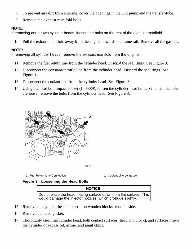
11. Remove the fuel return line from the cylinder head. Discard the seal rings. See Figure 3.
12. Disconnect the constant-throttle line from the cylinder head. Discard the seal rings. SeeFigure 1.
13. Disconnect the coolant line from the cylinder head. See Figure 3.
14. Using the head bolt impact socket (J-45389), loosen the cylinder head bolts. When all the boltsare loose, remove the bolts from the cylinder head. See Figure 3.
1. Fuel Return Line Connection 2. Coolant Line connection
Figure 3 Loosening the Head Bolts
NOTICE:
Do not place the head mating surface down on a flat surface. Thiswould damage the injector nozzles, which protrude slightly.
15. Remove the cylinder head and set it on wooden blocks or on its side.
16. Remove the head gasket.
17. Thoroughly clean the cylinder head, both contact surfaces (head and block), and surfaces insidethe cylinder of excess oil, grime, and paint chips.
18. With a straightedge, check the cylinder head surface for warpage. Refer to section . Listed inTable 1 are warpage limits.
Description Limit: mm (in.)
Over a length of 150 mm (6 in.) 0.1 mm (0.004)
Table 1 Head Warpage Limits
19. Check the cylinder liner protrusion from the cylinder block. Listed in Table 2 are thespecifications. Refer to section .
Description Value: mm (in.)
Cylinder Liner Protrusion from block 0.230-0.330 mm (0.0090-0.0130 in.)
Difference between the four measuring points Max.: 0.02 mm (0.0007 in.)
Table 2 Specifications for Measuring Cylinder Liner Protrusion
20. Inspect the cylinder head for cracks or signs of damage. Replace if necessary.
CYLINDER HEAD INSPECTION AND MACHINING
Inspection
1. Remove the cylinder head.
2. Remove the nozzle holder.
3. Remove the intake and exhaust valves. Refer to section .
4. Remove the constant-throttle valve. Refer to section .
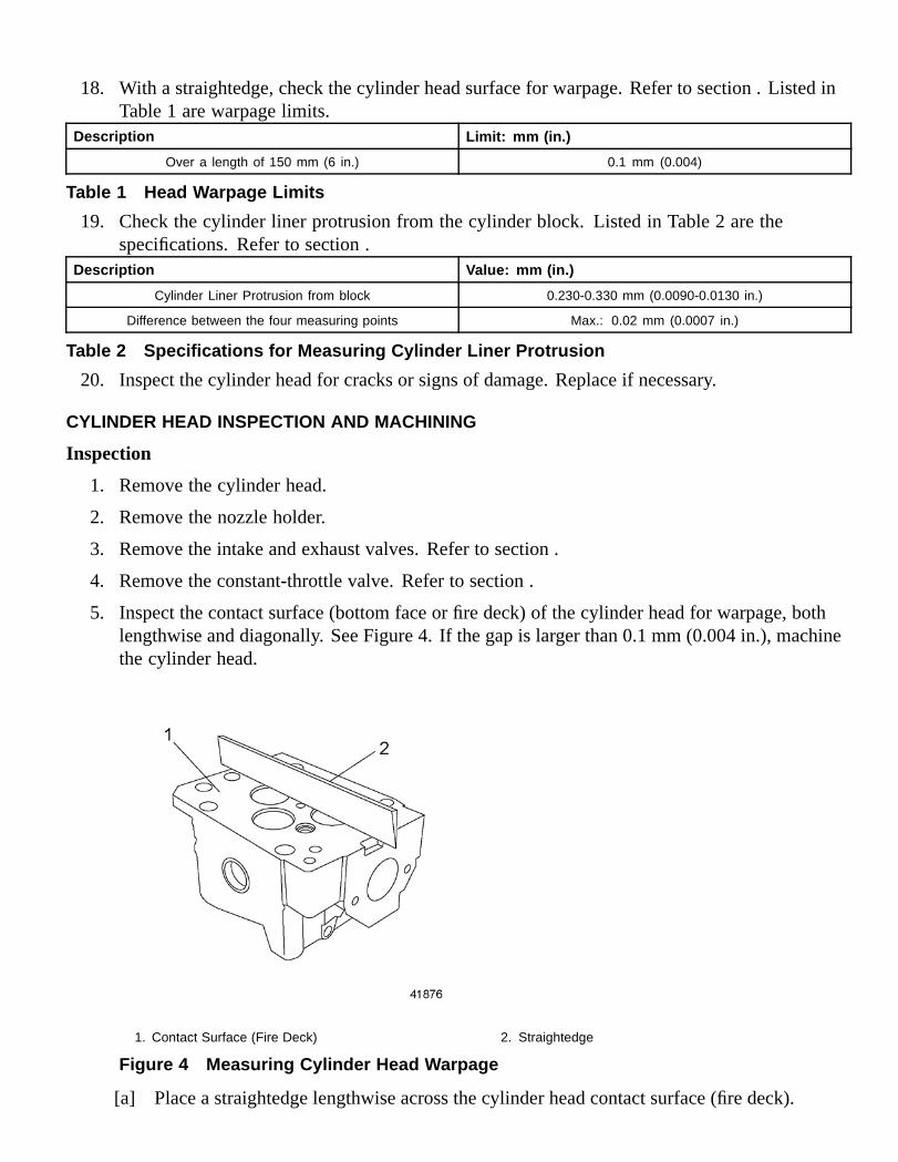
5. Inspect the contact surface (bottom face or fire deck) of the cylinder head for warpage, bothlengthwise and diagonally. See Figure 4. If the gap is larger than 0.1 mm (0.004 in.), machinethe cylinder head.
1. Contact Surface (Fire Deck) 2. Straightedge
Figure 4 Measuring Cylinder Head Warpage
[a] Place a straightedge lengthwise across the cylinder head contact surface (fire deck).
[b] If there is a gap between the lower edge of the straightedge and the contact surface of thecylinder head that is large enough to let light through, insert a feeler gauge into the gap.
[c] Measure the amount of warpage with the feeler gauge and compare it to the value listed inTable 3. If the gap is larger than 0.1 mm (0.004 in.), machine the cylinder head.
What To Measure How To Measure Specification: mm (in.)
Maximum Permissible Warpage ofHead Mating Surface
Lengthwise and Diagonally 0.1 (0.004)
Maximum Permissible ParallelismDeviation of Head Mating Surface
At Each of the Four Corners 0.1 (0.004)
When New 113.85-114.15 (4.482-4.494)Overall Height of Cylinder Head
After Machining 113.5 (4.46)
Table 3 Cylinder Head Specifications
[d] Place the straightedge diagonally across the cylinder head. Repeat the procedure above.
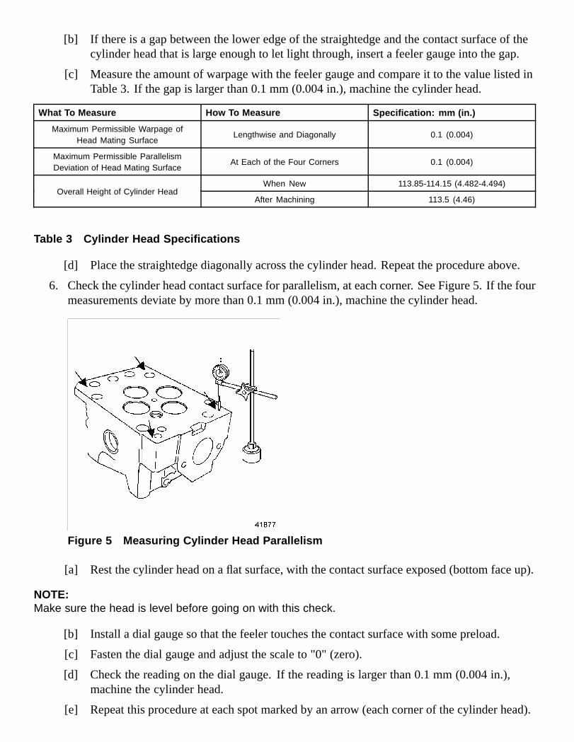
6. Check the cylinder head contact surface for parallelism, at each corner. See Figure 5. If the fourmeasurements deviate by more than 0.1 mm (0.004 in.), machine the cylinder head.
Figure 5 Measuring Cylinder Head Parallelism
[a] Rest the cylinder head on a flat surface, with the contact surface exposed (bottom face up).
NOTE:Make sure the head is level before going on with this check.
[b] Install a dial gauge so that the feeler touches the contact surface with some preload.
[c] Fasten the dial gauge and adjust the scale to "0" (zero).
[d] Check the reading on the dial gauge. If the reading is larger than 0.1 mm (0.004 in.),machine the cylinder head.
[e] Repeat this procedure at each spot marked by an arrow (each corner of the cylinder head).
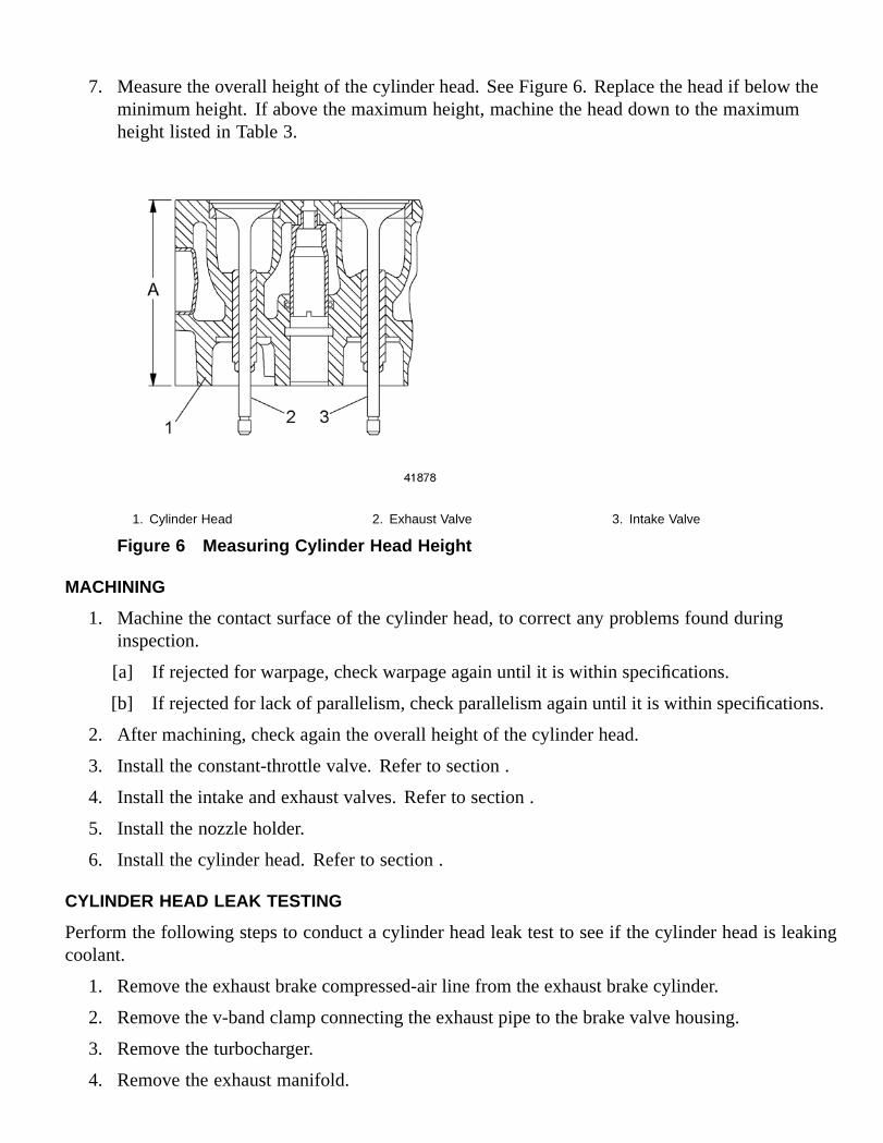
7. Measure the overall height of the cylinder head. See Figure 6. Replace the head if below theminimum height. If above the maximum height, machine the head down to the maximumheight listed in Table 3.
1. Cylinder Head 2. Exhaust Valve 3. Intake Valve
Figure 6 Measuring Cylinder Head Height
MACHINING
1. Machine the contact surface of the cylinder head, to correct any problems found duringinspection.
[a] If rejected for warpage, check warpage again until it is within specifications.
[b] If rejected for lack of parallelism, check parallelism again until it is within specifications.
2. After machining, check again the overall height of the cylinder head.
3. Install the constant-throttle valve. Refer to section .
4. Install the intake and exhaust valves. Refer to section .
5. Install the nozzle holder.
6. Install the cylinder head. Refer to section .
CYLINDER HEAD LEAK TESTING
Perform the following steps to conduct a cylinder head leak test to see if the cylinder head is leakingcoolant.
1. Remove the exhaust brake compressed-air line from the exhaust brake cylinder.
2. Remove the v-band clamp connecting the exhaust pipe to the brake valve housing.
3. Remove the turbocharger.
4. Remove the exhaust manifold.
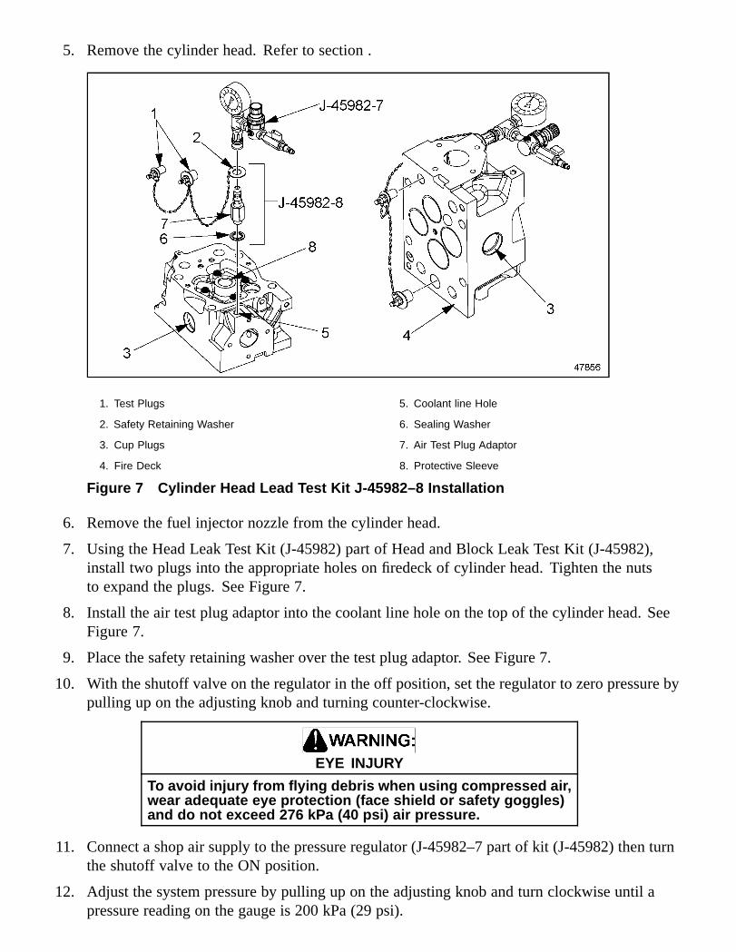
5. Remove the cylinder head. Refer to section .
1. Test Plugs 5. Coolant line Hole
2. Safety Retaining Washer 6. Sealing Washer
3. Cup Plugs 7. Air Test Plug Adaptor
4. Fire Deck 8. Protective Sleeve
Figure 7 Cylinder Head Lead Test Kit J-45982–8 Installation
6. Remove the fuel injector nozzle from the cylinder head.
7. Using the Head Leak Test Kit (J-45982) part of Head and Block Leak Test Kit (J-45982),install two plugs into the appropriate holes on firedeck of cylinder head. Tighten the nutsto expand the plugs. See Figure 7.
8. Install the air test plug adaptor into the coolant line hole on the top of the cylinder head. SeeFigure 7.
9. Place the safety retaining washer over the test plug adaptor. See Figure 7.
10. With the shutoff valve on the regulator in the off position, set the regulator to zero pressure bypulling up on the adjusting knob and turning counter-clockwise.
EYE INJURY
To avoid injury from flying debris when using compressed air,wear adequate eye protection (face shield or safety goggles)and do not exceed 276 kPa (40 psi) air pressure.
11. Connect a shop air supply to the pressure regulator (J-45982–7 part of kit (J-45982) then turnthe shutoff valve to the ON position.
12. Adjust the system pressure by pulling up on the adjusting knob and turn clockwise until apressure reading on the gauge is 200 kPa (29 psi).
13. Connect the Regulator and Gauge (J-45982–7 part of kit J–45982) to the air test plug on thecylinder head. See Figure 7.
14. Check for leaks around the test plugs and fittings with a soapy water solution. Repair anyleaks found.
15. With a soapy water solution, check the cup plugs on the sides of the cylinder head and theinjector nozzle protective sleeve area.
[a] If the cup plug(s) are leaking, replace the plug(s).
[b] If the injector protective sleeve is leaking, replace the protective sleeve O-ring.
16. Close the air supply and watch the pressure gauge for 30 seconds. If the air pressure dropsduring this time the cylinder head has leakage from the cooling passages and is not suitablefor reuse.
17. Remove the test equipment from the cylinder head and repeat leak test for any additionalcylinder heads.
18. Install the fuel injector nozzle in the cylinder head.
19. Install the cylinder head. Refer to section .
20. Install the exhaust manifold.
21. Install the turbocharger.
22. Install the compressed-air line on the exhaust brake cylinder.
23. Clean the sealing surfaces on the exhaust pipe and brake valve housing.
24. Slide the exhaust pipe and clamp over the end of the housing. Tighten the clamp.
SPECIFICATIONS
This section contains the specifications for servicing the engine.
CYLINDER HEAD COVER
The torque specifications for the cylinder head cover are listed in Table 4.
Description Torque Value: N·m (lb·ft)
Cylinder Head Cover Bolts 20 (15 )
Table 4 Cylinder Head Cover Torque Values
CYLINDER HEAD
The cylinder head warpage limits are listed in Table 5. The specifications for measuring cylinder linerprotrusion are listed in Table 6. Cylinder head bolt length is listed in Table 7. The tightening stages forcylinder head bolts are listed in Table 8. Oil pressure readings are listed in Table 9. Cylinder head torquevalues are listed in Table 10. Cylinder head specifications are listed in Table 11. The specifications forcompression testing are listed in Table 12 and listed in Table 13.
Description Limit: mm (in.)
Over a length of 150 mm (6 in.) 0.1 (0.004)
Table 5 Head Warpage LimitsDescription Value: mm (in.)
Cylinder Liner Protrusion from block 0.2305-0.330 (0.0090-0.0130)
Difference between the four measuring points Max.: 0.02 (0.0007)
Table 6 Specifications for Measuring Cylinder Liner ProtrusionDescription Length: mm (in.)
Shaft length when new 210.0 (8.27)
Maximum shaft length 212.0 (8.35)
Table 7 Cylinder Head Bolt LengthsSize Max. Shaft Length: mm
(in.)Tightening Stage Torque Value: N·m (lb·ft)
Stage 1 10 (7)
Stage 2 50 (37)
Stage 3 100 (74)
Stage 4 200 (148)
Stage 5 additional 90°
M15 x 2 212.0 (8.35)
Stage 6 additional 90°
Table 8 Tightening Stages, Cylinder Head BoltsDescription Minimum Oil Pressure Reading: kPa (psi)
Engine at Idle Speed 50 (7)
Engine at Max. rpm 250 (36)
Table 9 Oil Pressure ReadingsDescription Torque Value: N·m (lb·ft)
Exhaust Manifold Bolts 50 N·m (37 lb·ft); then another 90°
High-Pressure Fuel Lines 25 N·m (18 lb·ft)
Inspection Cover on Flywheel Housing 25 N·m (18 lb·ft)
Rocker Arm Mounting Bolts 60 N·m (44 lb·ft); then another 90°
Table 10 Cylinder Head Torque ValuesWhat To Measure How To Measure Specification: mm (in.)
Maximum Permissible Warpage ofHead Mating Surface
Lengthwise and Diagonally 0.1 (0.004)
Maximum Permissible ParallelismDeviation of Head Mating Surface
At Each of the Four Corners 0.1 (0.004)
When New 113.85-114.15 (4.482-4.494)Overall Height of Cylinder Head
After Machining 113.5 (4.46)
Table 11 Cylinder Head SpecificationsDescription Pressure: kPa (psi)
Minimum Compression Pressure Valve 2800 (406)
Permissible Difference Between Individual Cylinders 400 (58)
Table 12 Compression Pressure Test Data
Description Torque Value: N·m (lb·ft)
Tensioning Arm Bolts 50 (37)
Table 13 Tensioning Arm Bolt Torque Values
CYLINDER BLOCK
The cylinder liner installation tolerances are listed in Table 14. The cylinder liner inspection tolerancesare listed in Table 15. Cylinder Liner measurements are listed in Table 16. The specifications formeasuring cylinder liner protrusion are listed in Table 17.
Description Specification: mm (in.)
Cylinder Liner Protrusion, From Block, , Ref. A. 0.230–0.330 (0.0090–0.0130)
Height of the Cylinder Liner Collar, , Ref. B. 10.10–10.12 (0.3976–0.3984)
Depth of the Collar Seat, , Ref. C. 9.950–10.010 (0.392–0.3941)
Thickness of the Seat Insert 0.14–0.16 (0.0055–0.0063)
Table 14 Cylinder Liner Installation Tolerances
Description Specification: mm (in.)
Admissible Out-of-Round of the Cylinder Liner, whereit contacts the O-rings
Max.: 0.02 (0.0007)
Admissible Deformation of the Cylinder Liner Collar, atthe Contact Surface with the Seat Insert
Max.: 0.02 (0.0007)
Admissible Deformation of the Liner Collar Seat, at theContact Surface with the Seat Insert
Max.: 0.03 (0.0011)
Table 15 Cylinder Liner Inspection Tolerances
Where To Measure What To Measure Specification: mm (in.)
Measuring Point 1: at the O-ring area Inside Diameter of the CylinderLiner, A class
127.990–127.995 (5.0390–5.0392)
Measuring Point 1: at the O-ring area Inside Diameter of the CylinderLiner, B class
127.995–128.005 (5.0392–5.0396)
Measuring Point 1: at the O-ring area Inside Diameter of the CylinderLiner, C class
128.005–128.010 (5.0396–5.0398)
Measuring Point 2: Upper ReversalPoint of the First Piston Ring
Max. Wear to Cylinder Liner, MeasuredAlong Axis A and Axis B
0.08 (0.003)
At Measuring Point 2, CompareAxis A to Axis B
Admissible Wear-Out Max.: 0.08 (0.003)
Table 16 Cylinder Liner Measurements
Description Specification: mm (in.)
Cylinder Liner Protrusion From Block 0.245–0.315 (0.0096–0.0124)
Difference Between the Four Measuring Points Max.: 0.02 (0.0007)
Table 17 Specifications for Measuring Cylinder Liner Protrusion

The following applies to DDC-SVC-MAN-0026:
2 Description and Operation of the Cylinder Head
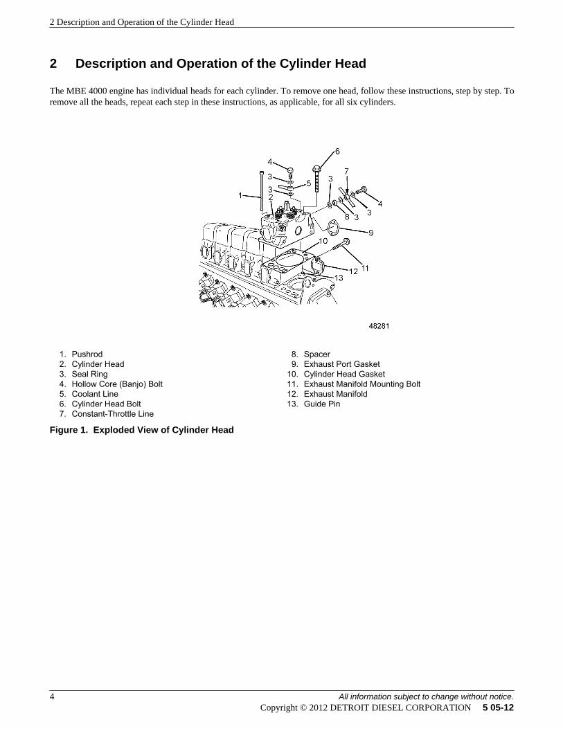
The MBE 4000 engine has individual heads for each cylinder. To remove one head, follow these instructions, step by step. Toremove all the heads, repeat each step in these instructions, as applicable, for all six cylinders.
1. Pushrod2. Cylinder Head3. Seal Ring4. Hollow Core (Banjo) Bolt5. Coolant Line6. Cylinder Head Bolt7. Constant-Throttle Line
8. Spacer9. Exhaust Port Gasket
10. Cylinder Head Gasket11. Exhaust Manifold Mounting Bolt12. Exhaust Manifold13. Guide Pin
Figure 1. Exploded View of Cylinder Head
2 Description and Operation of the Cylinder Head
4 All information subject to change without notice.Copyright © 2012 DETROIT DIESEL CORPORATION 5 05-12
3 Removal of the Cylinder Head
Removal steps are as follows:
WARNING: HOT COOLANT
To avoid scalding from the expulsion of hot coolant, never remove the cooling system pressure capwhile the engine is at operating temperature. Wear adequate protective clothing (face shield, rubbergloves, apron, and boots). Remove the cap slowly to relieve pressure.
1. Drain the coolant from the radiator. Refer to section "Draining and Flushing the Cooling System" .
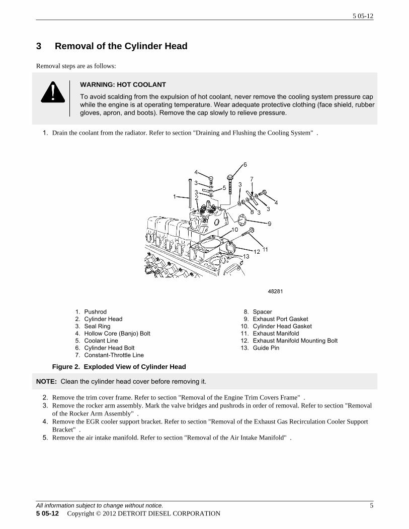
1. Pushrod2. Cylinder Head3. Seal Ring4. Hollow Core (Banjo) Bolt5. Coolant Line6. Cylinder Head Bolt7. Constant-Throttle Line
8. Spacer9. Exhaust Port Gasket
10. Cylinder Head Gasket11. Exhaust Manifold12. Exhaust Manifold Mounting Bolt13. Guide Pin
Figure 2. Exploded View of Cylinder Head
NOTE: Clean the cylinder head cover before removing it.
2. Remove the trim cover frame. Refer to section "Removal of the Engine Trim Covers Frame" .3. Remove the rocker arm assembly. Mark the valve bridges and pushrods in order of removal. Refer to section "Removal
of the Rocker Arm Assembly" .4. Remove the EGR cooler support bracket. Refer to section "Removal of the Exhaust Gas Recirculation Cooler Support
Bracket" .5. Remove the air intake manifold. Refer to section "Removal of the Air Intake Manifold" .
5 05-12
All information subject to change without notice. 55 05-12 Copyright © 2012 DETROIT DIESEL CORPORATION
WARNING: PERSONAL INJURY
To prevent the escape of high pressure fuel that can penetrate skin, ensure the engine has been shutdown for a minimum of 10 minutes before servicing any component within the high pressure circuit.Residual high fuel pressure may be present within the circuit.
NOTICE: Do not move the thrust bolt, because there is danger of causing a change in the position of the transfer-tube. If the position of the transfer-tube is changed, engine damage could result.
6. Remove the high-pressure fuel line and transfer tube. Refer to section "Removal of the High Pressure Fuel Line andTransfer Tube" .
7. To prevent any dirt from entering, cover the openings in the unit.
NOTE: If removing one or two cylinder heads, loosen the bolts on the rest of the exhaust manifold.
8. Remove the turbocharger from the exhaust manifold. Refer to section "Removal of the Turbocharger" .
NOTE: If removing all cylinder heads, remove the exhaust manifold from the engine.
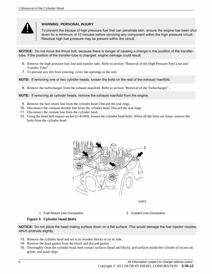
9. Remove the fuel return line from the cylinder head. Discard the seal rings.10. Disconnect the constant throttle line from the cylinder head. Discard the seal rings.11. Disconnect the coolant line from the cylinder head.12. Using the head bolt impact socket (J–45389), loosen the cylinder head bolts. When all the bolts are loose, remove the
bolts from the cylinder head.
1. Fuel Return Line Connection 2. Coolant Line Connection
Figure 3. Cylinder Head Bolts
NOTICE: Do not place the head mating surface down on a flat surface. This would damage the fuel injector nozzles,which protrude slightly.
13. Remove the cylinder head and set it on wooden blocks or on its side.14. Remove the head gasket from the block and discard gasket.15. Thoroughly clean the cylinder head, both contact surfaces (head and block), and surfaces inside the cylinder of excess oil,
grime, and paint chips.
3 Removal of the Cylinder Head
6 All information subject to change without notice.Copyright © 2012 DETROIT DIESEL CORPORATION 5 05-12
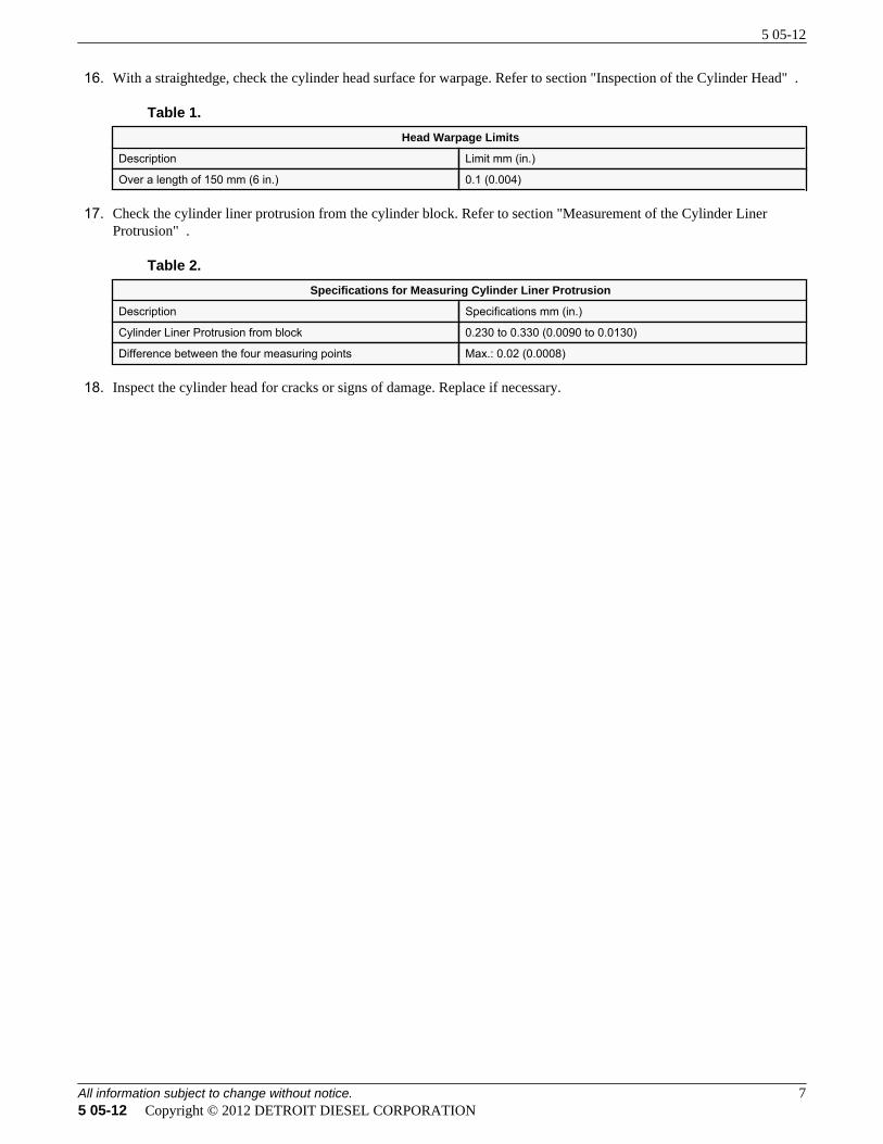
16. With a straightedge, check the cylinder head surface for warpage. Refer to section "Inspection of the Cylinder Head" .
Table 1.Head Warpage Limits
Description Limit mm (in.)
Over a length of 150 mm (6 in.) 0.1 (0.004)
17. Check the cylinder liner protrusion from the cylinder block. Refer to section "Measurement of the Cylinder LinerProtrusion" .
Table 2.Specifications for Measuring Cylinder Liner Protrusion
Description Specifications mm (in.)
Cylinder Liner Protrusion from block 0.230 to 0.330 (0.0090 to 0.0130)
Difference between the four measuring points Max.: 0.02 (0.0008)
18. Inspect the cylinder head for cracks or signs of damage. Replace if necessary.
5 05-12
All information subject to change without notice. 75 05-12 Copyright © 2012 DETROIT DIESEL CORPORATION
4 Inspection of the Cylinder Head
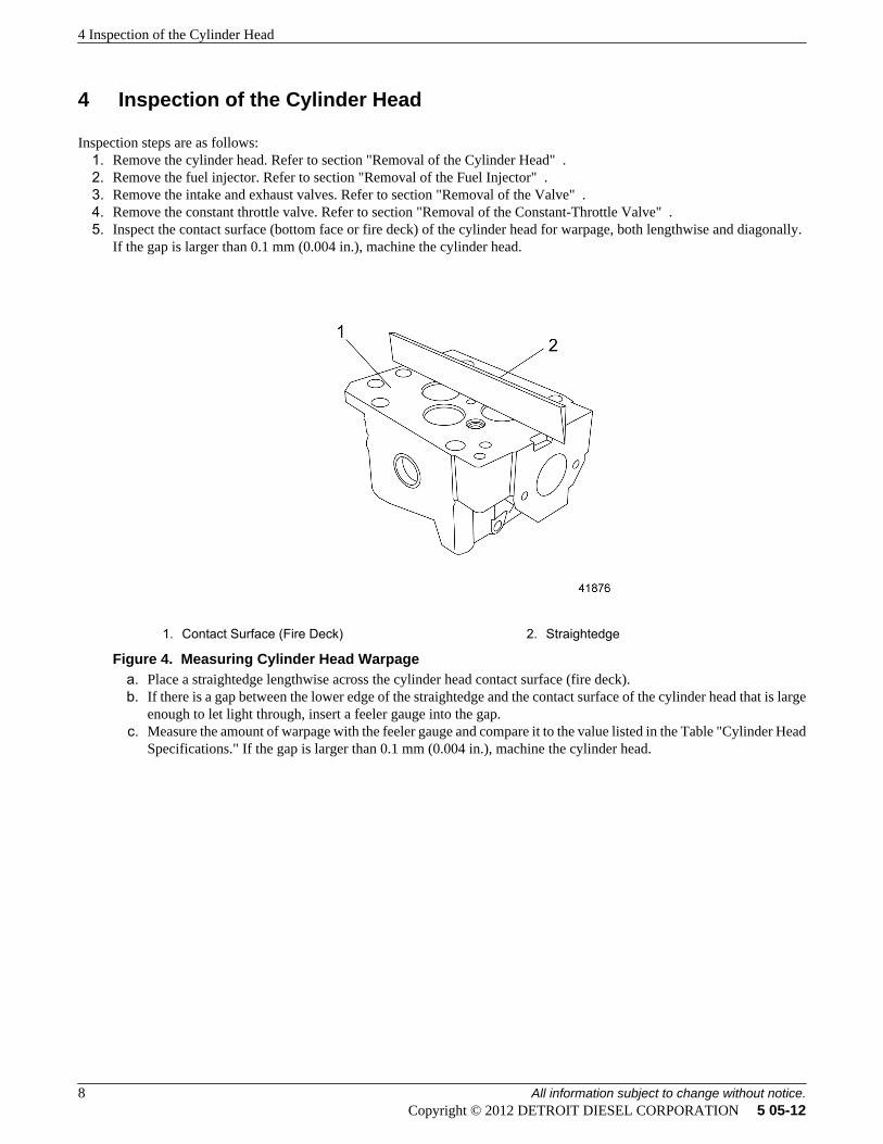
Inspection steps are as follows:1. Remove the cylinder head. Refer to section "Removal of the Cylinder Head" .2. Remove the fuel injector. Refer to section "Removal of the Fuel Injector" .3. Remove the intake and exhaust valves. Refer to section "Removal of the Valve" .4. Remove the constant throttle valve. Refer to section "Removal of the Constant-Throttle Valve" .5. Inspect the contact surface (bottom face or fire deck) of the cylinder head for warpage, both lengthwise and diagonally.
If the gap is larger than 0.1 mm (0.004 in.), machine the cylinder head.
1. Contact Surface (Fire Deck) 2. Straightedge
Figure 4. Measuring Cylinder Head Warpagea. Place a straightedge lengthwise across the cylinder head contact surface (fire deck).b. If there is a gap between the lower edge of the straightedge and the contact surface of the cylinder head that is large
enough to let light through, insert a feeler gauge into the gap.c. Measure the amount of warpage with the feeler gauge and compare it to the value listed in the Table "Cylinder Head
Specifications." If the gap is larger than 0.1 mm (0.004 in.), machine the cylinder head.
4 Inspection of the Cylinder Head
8 All information subject to change without notice.Copyright © 2012 DETROIT DIESEL CORPORATION 5 05-12
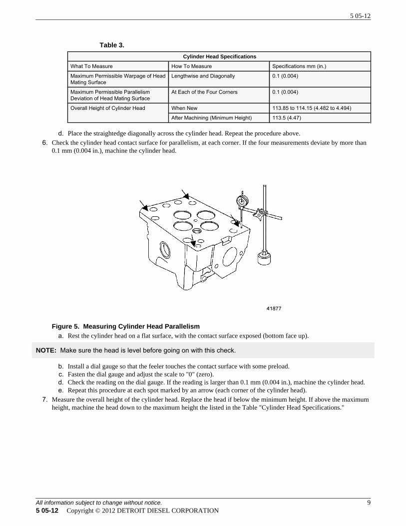
Table 3.Cylinder Head Specifications
What To Measure How To Measure Specifications mm (in.)
Maximum Permissible Warpage of HeadMating Surface
Lengthwise and Diagonally 0.1 (0.004)
Maximum Permissible ParallelismDeviation of Head Mating Surface
At Each of the Four Corners 0.1 (0.004)
Overall Height of Cylinder Head When New 113.85 to 114.15 (4.482 to 4.494)
After Machining (Minimum Height) 113.5 (4.47)
d. Place the straightedge diagonally across the cylinder head. Repeat the procedure above.6. Check the cylinder head contact surface for parallelism, at each corner. If the four measurements deviate by more than
0.1 mm (0.004 in.), machine the cylinder head.
Figure 5. Measuring Cylinder Head Parallelisma. Rest the cylinder head on a flat surface, with the contact surface exposed (bottom face up).
NOTE: Make sure the head is level before going on with this check.
b. Install a dial gauge so that the feeler touches the contact surface with some preload.c. Fasten the dial gauge and adjust the scale to "0" (zero).d. Check the reading on the dial gauge. If the reading is larger than 0.1 mm (0.004 in.), machine the cylinder head.e. Repeat this procedure at each spot marked by an arrow (each corner of the cylinder head).
7. Measure the overall height of the cylinder head. Replace the head if below the minimum height. If above the maximumheight, machine the head down to the maximum height the listed in the Table "Cylinder Head Specifications."
5 05-12
All information subject to change without notice. 95 05-12 Copyright © 2012 DETROIT DIESEL CORPORATION
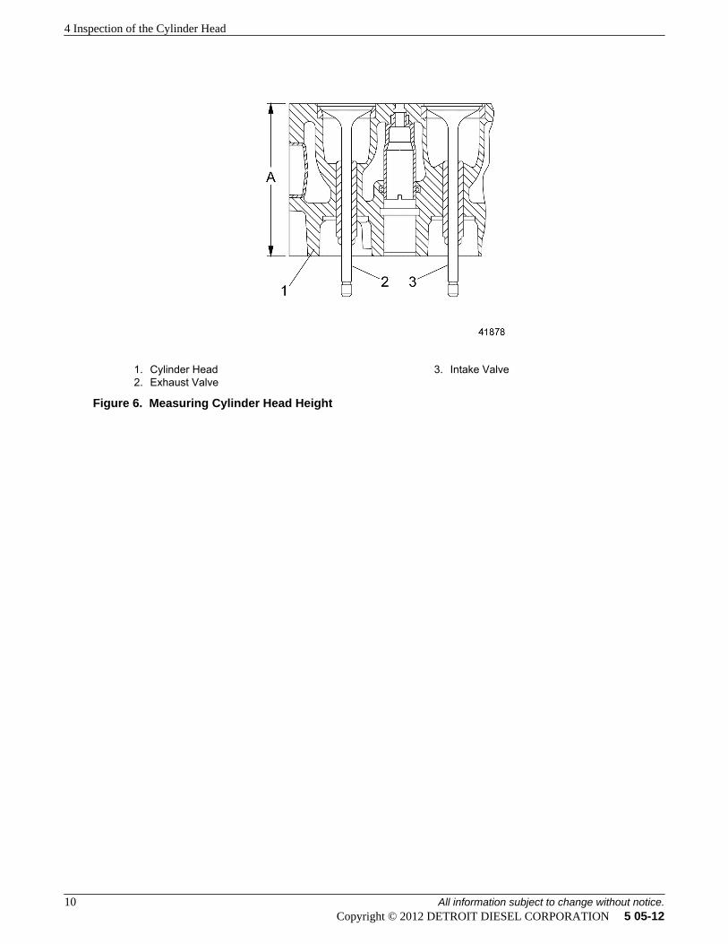
1. Cylinder Head2. Exhaust Valve
3. Intake Valve
Figure 6. Measuring Cylinder Head Height
4 Inspection of the Cylinder Head
10 All information subject to change without notice.Copyright © 2012 DETROIT DIESEL CORPORATION 5 05-12
5 Additional Engine Information - Cylinder Head Cover
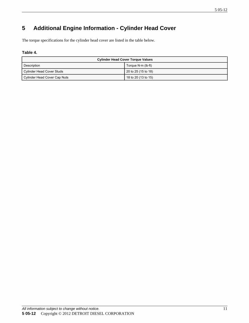
The torque specifications for the cylinder head cover are listed in the table below.
Table 4.Cylinder Head Cover Torque Values
Description Torque N·m (lb·ft)
Cylinder Head Cover Studs 20 to 25 (15 to 18)
Cylinder Head Cover Cap Nuts 18 to 20 (13 to 15)
5 05-12
All information subject to change without notice. 115 05-12 Copyright © 2012 DETROIT DIESEL CORPORATION
6 Additional Engine Information - Cylinder Head
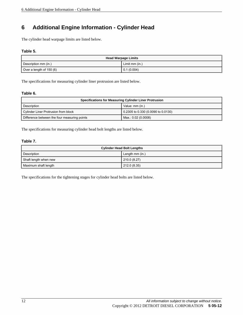
The cylinder head warpage limits are listed below.
Table 5.Head Warpage Limits
Description mm (in.) Limit mm (in.)
Over a length of 150 (6) 0.1 (0.004)
The specifications for measuring cylinder liner protrusion are listed below.
Table 6.Specifications for Measuring Cylinder Liner Protrusion
Description Value: mm (in.)
Cylinder Liner Protrusion from block 0.2305 to 0.330 (0.0090 to 0.0130)
Difference between the four measuring points Max.: 0.02 (0.0008)
The specifications for measuring cylinder head bolt lengths are listed below.
Table 7.Cylinder Head Bolt Lengths
Description Length mm (in.)
Shaft length when new 210.0 (8.27)
Maximum shaft length 212.0 (8.35)
The specifications for the tightening stages for cylinder head bolts are listed below.
6 Additional Engine Information - Cylinder Head
12 All information subject to change without notice.Copyright © 2012 DETROIT DIESEL CORPORATION 5 05-12
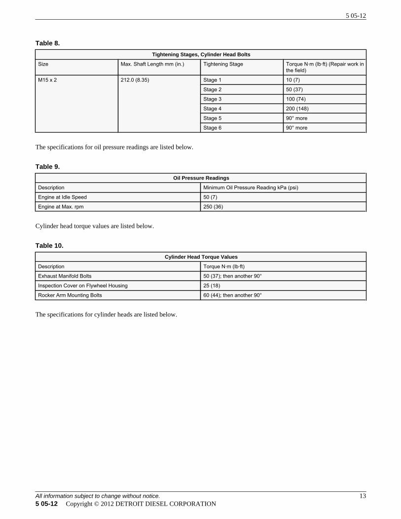
Table 8.Tightening Stages, Cylinder Head Bolts
Size Max. Shaft Length mm (in.) Tightening Stage Torque N·m (lb·ft) (Repair work inthe field)
M15 x 2 212.0 (8.35) Stage 1 10 (7)
Stage 2 50 (37)
Stage 3 100 (74)
Stage 4 200 (148)
Stage 5 90° more
Stage 6 90° more
The specifications for oil pressure readings are listed below.
Table 9.Oil Pressure Readings
Description Minimum Oil Pressure Reading kPa (psi)
Engine at Idle Speed 50 (7)
Engine at Max. rpm 250 (36)
Cylinder head torque values are listed below.
Table 10.Cylinder Head Torque Values
Description Torque N·m (lb·ft)
Exhaust Manifold Bolts 50 (37); then another 90°
Inspection Cover on Flywheel Housing 25 (18)
Rocker Arm Mounting Bolts 60 (44); then another 90°
The specifications for cylinder heads are listed below.
5 05-12
All information subject to change without notice. 135 05-12 Copyright © 2012 DETROIT DIESEL CORPORATION
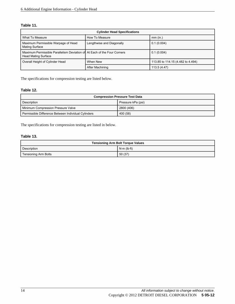
Table 11.Cylinder Head Specifications
What To Measure How To Measure mm (in.)
Maximum Permissible Warpage of HeadMating Surface
Lengthwise and Diagonally 0.1 (0.004)
Maximum Permissible Parallelism Deviation ofHead Mating Surface
At Each of the Four Corners 0.1 (0.004)
Overall Height of Cylinder Head When New 113.85 to 114.15 (4.482 to 4.494)
After Machining 113.5 (4.47)
The specifications for compression testing are listed below.
Table 12.Compression Pressure Test Data
Description Pressure kPa (psi)
Minimum Compression Pressure Valve 2800 (406)
Permissible Difference Between Individual Cylinders 400 (58)
The specifications for compression testing are listed in below.
Table 13.Tensioning Arm Bolt Torque Values
Description N·m (lb·ft)
Tensioning Arm Bolts 50 (37)
6 Additional Engine Information - Cylinder Head
14 All information subject to change without notice.Copyright © 2012 DETROIT DIESEL CORPORATION 5 05-12