Embed Size (px)
Citation preview
HM-40029-3
5-Phase Stepping Motor Unit
RK Series
OPERATING MANUAL
Thank you for purchasing an Oriental Motor product. This Operating Manual describes product handling procedures and safety precautions. • Please read it thoroughly to ensure safe operation. • Always keep the manual where it is readily available.

Table of contents
− 2 −
1 Introduction.........................................3
2 Safety precautions ..............................6
3 Precautions for use.............................8
4 Preparation .......................................10 4.1 Checking the product ............................ 10 4.2 How to identify the product model......... 11 4.3 Combinations of motors and drivers ..... 12 4.4 Names and functions of parts................ 15
5 Installation.........................................18 5.1 Location for installation.......................... 18 5.2 Installing the motor ................................ 19 5.3 Installing a load ..................................... 20 5.4 Permissible overhung load and
permissible thrust load .......................... 22 5.5 Installing the driver ................................ 24 5.6 Installing and wiring in compliance
with EMC Directive ................................ 25
6 Connection........................................28 6.1 Connection example for a
standard type......................................... 28 6.2 Connection example for a standard type
with electromagnetic brake .................... 29 6.3 Connecting the power supply................ 31 6.4 Connecting the motor and driver,
grounding the motor .............................. 32 6.5 Connecting and grounding of
standard type terminal box.................... 33 6.6 Grounding the driver.............................. 34 6.7 Connecting the input/output signals ...... 35 6.8 About input/output signals..................... 37 6.9 Timing chart........................................... 43
7 Setting...............................................44 7.1 Step angle ............................................. 44 7.2 Adjusting motor currents ....................... 45 7.3 Pulse input modes................................. 46 7.4 Automatic current off function ............... 46 7.5 Smooth drive function ........................... 47 7.6 Electromagnetic brake function and
energy saver mode (motors with an electromagnetic brake only) .................. 48
7.7 Operating the motor with an electromagnetic brake........................... 49
8 Overheat protection function.............52 8.1 Stopping the motor operation................ 52 8.2 Allowing the motor operation to
continue................................................. 52 8.3 Canceling the O.H. (overheat) output ... 52
9 Inspection .........................................53
10 Troubleshooting and remedial actions ..............................................54
11 Specifications....................................56
12 Option (Sold separately) ...................57
1 Introduction
− 3 −
1 Introduction
Before using the motor unit Only qualified personnel should work with the product. Use the product correctly after thoroughly reading the section “Safety precautions”. The product described in this manual has been designed and manufactured for use in general industrial machinery, and must not be used for any other purpose. Oriental Motor Co., Ltd. is not responsible for any damage caused through failure to observe this warning.
Overview of the product The RK series 5-phase stepping motors are unit products consisting of high-performance micro-stepping driver and a 5-phase stepping motor of high-torque, low-vibration design. Oriental Motor has achieved low-vibration and low-noise operation through the use of a micro-stepping drive that electrically divides the motor’s basic step angle.
Main features
• Capable of low-speed operation at a low vibration level The RK series achieves smooth, low-speed operation at an extremely low vibration level as a result of incorporating a micro-stepping drive, which enables very small angle stepping.
• Smooth drive The smooth drive function automatically performs 16-division microstep drive inside the driver, without changing the input pulse frequency and resolution, thereby ensuring low vibration and noise during low-speed operation. The factory setting is “OFF: Smooth drive disabled”.
• Built-in overheat protection A driver’s internal temperature in excess of 80 °C (176 °F) triggers overheat protection whereby the O.H. (overheat) output is turned to “OFF” (normally “ON” in order to warn the user of an abnormality). As to the action to be taken when the overheat protection function is activated, the user may elect to stop the motor (the factory setting A.C.O.- “Automatic current off” -enabled) or continue the operation (OFF: disabled).
• Adjustable operating current A digital switch adjusts the level of motor current during operation and in the stopped state.
• Preset and selectable resolution Two motor resolution levels may be preset in 16 steps with a desired level selected via the controller.
• Energy saver mode (motors with an electromagnetic brake only) Once the motor stops, its output current is turned OFF and the load is held in position with the electromagnetic brake. This is effective in reducing power consumption and limiting the heat generated by the motor and driver.
1 Introduction
− 4 −
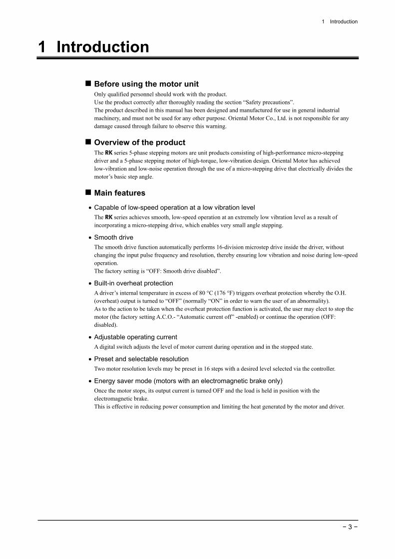
System configuration Controllers with pulse output functions are needed to operate the RK series 5-phase stepping motor units.
Controller(programmable controller and others)
Input and output signal
Positioning controller
Pulse output and input/output signal
RK series 5-phase stepping motor unit
Driver
Motor
Motor cable
Input and output signal
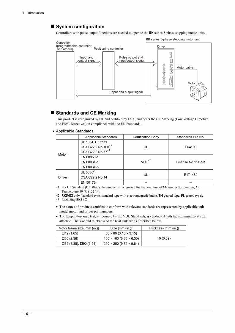
Standards and CE Marking This product is recognized by UL and certified by CSA, and bears the CE Marking (Low Voltage Directive and EMC Directives) in compliance with the EN Standards.
• Applicable Standards Applicable Standards Certification Body Standards File No.
UL 1004, UL 2111 CSA C22.2 No.100∗3 CSA C22.2 No.77∗3
UL E64199
Motor EN 60950-1 EN 60034-1 EN 60034-5
VDE∗2 License No.114293
UL 508C∗1 CSA C22.2 No.14
UL E171462 Driver
EN 50178 - - ∗1 For UL Standard (UL 508C), the product is recognized for the condition of Maximum Surrounding Air
Temperature 50 °C (122 °F). ∗2 RK54 only (standard type, standard type with electromagnetic brake, TH geared type, PL geared type). ∗3 Excluding RK54 .
• The names of products certified to conform with relevant standards are represented by applicable unit model motor and driver part numbers.
• The temperature-rise test, as required by the VDE Standards, is conducted with the aluminum heat sink attached. The size and thickness of the heat sink are as described below.
Motor frame size [mm (in.)] Size [mm (in.)] Thickness [mm (in.)] 42 (1.65) 80 × 80 (3.15 × 3.15) 60 (2.36) 160 × 160 (6.30 × 6.30)85 (3.35), 90 (3.54) 250 × 250 (9.84 × 9.84)
10 (0.39)

1 Introduction
− 5 −
• Installation conditions (EN Standard) Motor Driver
Single-phase 100−115 V
Motor is to be used as a component within other equipment. Overvoltage category: III (II)∗1 Pollution degree: 2 (3)∗2 Protection against electric shock: Class I
Driver is to be used as a component within other equipment. Overvoltage category: III (II)∗1 Pollution degree: 2 Protection against electric shock: Class I
Single-phase 200−230 V
Motor is to be used as a component within other equipment. Overvoltage category: II Pollution degree: 2 (3)∗2 Protection against electric shock: Class I
Driver is to be used as a component within other equipment. Overvoltage category: II Pollution degree: 2 Protection against electric shock: Class I
∗1 The specifications for the RK54 are shown in parentheses. ∗2 The specifications for the standard type terminal box are shown in parentheses.
• If a product of overvoltage category II is used and conformance to overvoltage category III is required, supply power through an insulated transformer.
• If conformance to pollution degree of 3 is required with a non-standard type terminal box, install the motor in an enclosure conforming to IP54.
• For Low Voltage Directive This product is designed for use as a built-in component. • Install the product within an enclosure in order to avoid contact with the hands. • Be sure to maintain a Protective Earth in case the hands should make contact with the product. Securely
ground the Protective Earth Terminals of the motor and driver.
• For EMC Directive (89/336/EEC, 92/31/EEC) This product has received EMC measures under the conditions specified in “Example of motor and driver installation and wiring” on page 27. Be sure to conduct EMC measures with the product assembled in your equipment by referring to “Installing and wiring in compliance with EMC Directive” on page 25.
Hazardous substances RoHS (Directive 2002/95/EC 27Jan.2003) compliant
2 Safety precautions
− 6 −
2 Safety precautions The precautions described below are intended to prevent danger or injury to the user and other personnel through safe, correct use of the product. Use the product only after carefully reading and fully understanding these instructions.
Warning Handling the product without observing the instructions that accompany a “Warning” symbol may result in serious injury or death.
Caution Handling the product without observing the instructions that accompany a “Caution” symbol may result in injury or property damage.
NoteNote The items under this heading contain important handling instructions that the user should observe to ensure safe use of the product.
Warning
General • Do not use the product in explosive or corrosive environments, in the presence of flammable gases,
locations subjected to splashing water, or near combustibles. Doing so may result in fire, electric shock or injury.
• Assign qualified personnel the task of installing, wiring, operating/controlling, inspecting and troubleshooting the product. Failure to do so may result in fire, electric shock, injury or damage to equipment.
• Do not transport, install the product, perform connections or inspections when the power is on. Always turn the power off before carrying out these operations. Failure to do so may result in electric shock.
• The terminals on the driver’s front panel marked with a symbol indicate the presence of high voltage. Do not touch these terminals while the power is on to avoid the risk of fire or electric shock.
• Provide a means to hold the moving parts in place for applications involving vertical travel. The motor loses holding torque when the power is shut off, allowing the moving parts to fall and possibly causing injury or damage to equipment.
• Do not use the motor’s built-in electromagnetic brake mechanism for stopping or for safety purposes. Using it for purposes other than holding the moving parts and motor in position may cause injury or damage to equipment.
• When the driver’s overheat-protection function is triggered, shut off the power immediately. Turn the power back on only after determining the cause. Continuing the operation without determining the cause of the problem may cause malfunction of the motor, leading to injury or damage to equipment.
Installation • To prevent the risk of electric shock, use the motor and driver for class I equipment only. • Install the motor and driver in their enclosures in order to prevent electric shock or injury. • Install the motor and driver so as to avoid contact with hands, or ground them to prevent the risk of electric
shock.
Connection • Keep the driver’s input power voltage within the specified range to avoid fire and electric shock. • Connect the cables securely according to the wiring diagram in order to prevent fire and electric shock. • Do not forcibly bend, pull or pinch the cable. Doing so may fire and electric shock. • To prevent electric shock, be sure to install the terminal cover (supplied) over the driver’s power supply
terminals after making connections.
Operation • Turn off the driver power in the event of a power failure, or the motor may suddenly start when the power
is restored and may cause injury or damage to equipment. • If A.C.O. (Automatic current off) on the driver’s overheat-protection function is disabled, set it so that the
motor is stopped upon detection of O.H. (overheat) output in order to prevent the risk of fire.
2 Safety precautions
− 7 −
• Do not turn the A.W.OFF (All windings off) input to “ON” while the motor is operating. The motor will stop and lose its holding ability, which may result in injury or damage to equipment.
Maintenance and inspection • Do not touch the connection terminals of the driver immediately after the power is turned off (for a period
of 15 seconds). The residual voltage may cause electric shock.
Repair, disassembly and modification • Do not disassemble or modify the motor or driver. This may cause electric shock or injury. Refer all such
internal inspections and repairs to the branch or sales office from which you purchased the product.
Caution
General • Do not use the motor and driver beyond their specifications, or electric shock, injury or damage to
equipment may result. • Keep your fingers and objects out of the openings in the motor and driver, or fire, electric shock or injury
may result. • Do not touch the motor or driver during operation or immediately after stopping. The surfaces are hot and
may cause a skin burn(s).
Transportation • Do not hold the motor output shaft or motor cable. This may cause injury.
Installation • Keep the area around the motor and driver free of combustible materials in order to prevent fire or a skin
burn(s). • To prevent the risk of damage to equipment, leave nothing around the motor and driver that would obstruct
ventilation. • Provide a cover over the rotating parts (output shaft) of the motor to prevent injury.
Operation • Use a motor and driver only in the specified combination. An incorrect combination may cause a fire. • Provide an emergency-stop device or emergency-stop circuit external to the equipment so that the entire
equipment will operate safely in the event of a system failure or malfunction. Failure to do so may result in injury.
• Before supplying power to the driver, turn all input signals to the driver to “OFF.” Otherwise, the motor may start suddenly and cause injury or damage to equipment.
• To prevent bodily injury, do not touch the rotating parts (output shaft) of the motor during operation. • Before moving the motor with the hands (as in the case of manual positioning), confirm that the driver
A.W.OFF (All windings off) input is “ON” prevent injury. • Immediately when trouble has occurred, stop running and turn off the driver power. Failure to do so may
result in fire, electric shock or injury. • To prevent electric shock, use only an insulated screwdriver to adjust the driver switches. • When operating the key-equipped motor by itself, be sure the key inserted into the output shaft is fixed in
position. Failure to do so may result in injury if the key should fly out. • The motor’s surface temperature may exceed 70 °C (158 °F), even under normal
operating conditions. If a motor is accessible during operation, post the warning label shown in the figure in a conspicuous position to prevent the risk of skin burn(s).
Warning label
Maintenance and inspection • To prevent the risk of electric shock, do not touch the terminals while measuring the insulation resistance or
conducting a voltage-resistance test.
Disposal • To dispose of the motor or driver, disassemble it into parts and components as much as possible and
dispose of individual parts/components as industrial waste.

3 Precautions for use
− 8 −
3 Precautions for use This section covers limitations and requirements the user should consider when using the RK series 5-phase stepping motor unit.
• Conduct the insulation resistance measurement or withstand voltage test separately on the motor and the driver. Conducting the insulation resistance measurement or withstand voltage test with the motor and driver connected may result in injury or damage to equipment.
• Do not apply an overhung load and thrust load in excess of the specified permissible limit. Be sure to operate the motor within the specified permissible limit of overhung load and thrust load. Operating it under an excessive overhung load and thrust load may damage the motor bearings (ball bearings).
• Operate the motor with a surface temperature not exceeding 100 °C (212 °F). The driver has an overheat-protection function, but the motor has no such feature. The motor casing’s surface temperature may exceed 100 °C (212 °F) under certain conditions (ambient temperature, operating speed, duty cycle, etc.). Keeping the surface temperature of the motor casing below 100 °C (212 °F) will also maximize the life of the motor bearings (ball bearings). When a harmonic geared type is used, make sure the gear case temperature is kept at 70 °C (158 °F) or below to prevent degradation of grease applied to the gear.
• About maximum static torque at excitation Maximum static torque at excitation represents a value obtained when the motor is excited using the rated current. When the motor is combined with a dedicated driver, the maximum static torque at excitation drops to approximately 50% due to the current cutback function that suppresses the rise in motor temperature in a standstill state. Acceleration and operation at the maximum static torque at excitation is possible in start-up, but it only has approximately 50% holding power after it has stopped. When selecting a motor for your application, consider the fact that the holding power will be reduced to approximately 50% after the motor has stopped.
• Install the driver in a vertical position. The driver’s heat-dissipation function is designed according to vertical orientation. Installing the driver in any other orientation may shorten the life of electronic parts due to temperature increases within the driver.
• Use the motor equipped with an electromagnetic brake for an application involving vertical travel. For an application involving vertical travel, select a motor equipped with an electromagnetic brake so that the load can be held in position. Use the electromagnetic brake to hold the load only after the motor stops. Do not use the electromagnetic brake for the purpose of stopping the motor. Repeated use of the electromagnetic brake for the purpose of stopping may cause excessive wear in the brake hub, thus reducing the brake’s holding capability. Since the electromagnetic brake is of the non-excitation type, it can also be used to hold the load in position in the event of a power failure. However, do not use the electromagnetic brake as a safety brake of your equipment, since it is not designed as a mechanism capable of securely holding the load.
• Connecting a motor with an electromagnetic brake The electromagnetic brake operates via the ON/OFF status of the driver’s internal DC power supply. When connecting the motor, verify that the connection for the electromagnetic brake’s lead wires has the correct polarity.
• Preventing leakage current Stray capacitance exists between the driver’s current-carrying line and other current-carrying lines, the earth and the motor, respectively. A high-frequency current may leak out through such capacitance, having a detrimental effect on the surrounding equipment. The actual leakage current depends on the driver’s switching frequency, the length of wiring between the driver and motor, and so on. When providing a leakage current breaker, use the following products, for instance, which have high-frequency signal protection: Mitsubishi Electric Corporation: NV series Fuji Electric FA Components & Systems Co., Ltd.: EG and SG series

3 Precautions for use
− 9 −
• Preventing electrical noise See 5.6 “Installing and wiring in compliance with EMC Directive” on page 25 for measures with regard to noise.
• About maximum torque of geared motor Always operate geared types with loads not exceeding their maximum torque. If a geared type is operated with a load exceeding the maximum torque, the gear will be damaged.
• About grease of geared motor On rare occasions, a small amount of grease may ooze out from of the geared motor. If there is concern over possible environmental damage resulting from the leakage of grease, check for grease stains during regular inspections. Alternatively, install an oil pan or other device to prevent leakage from causing further damage. Oil leakage may lead to problems in the customer’s equipment or products.
4 Preparation
− 10 −
4 Preparation This section covers the points to be checked along with the names and functions of respective parts.
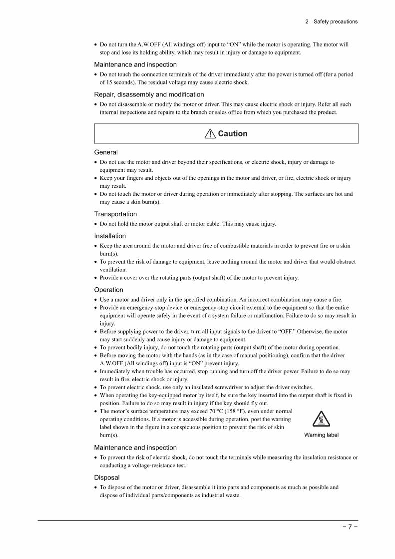
4.1 Checking the product Verify that the items listed below are included. Report any missing or damaged items to the branch or sales office from which you purchased the product. Verify the model number of the purchased unit against the number shown on the package label. Check the model number of the motor and driver against the number shown on the nameplate. The unit models and corresponding motor/driver combinations are listed on pages 12 to 14.
Motor∗ 1 unit Illustration shows the standerd type
with electromagnetic brake.
Driver 1 unitIllustration shows the driver
for RK56.
Input/output signal connector 1 set
Operating manual (this manual) 1 copy
∗ A parallel key (1 pc.) comes with all geared types (excluding TH geared types RK54 and RK56 and PL geared type RK54 ).
4 Preparation
− 11 −
4.2 How to identify the product model
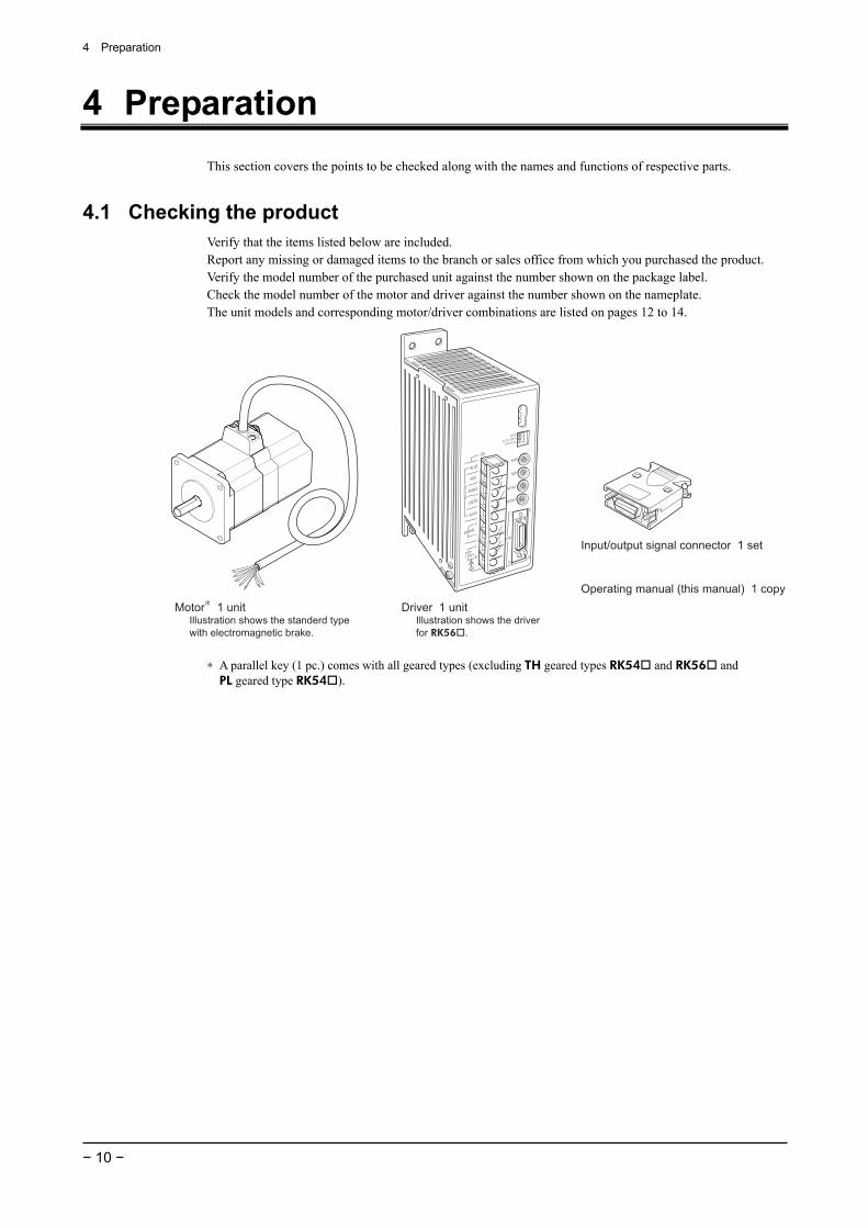
Standard type, Standard type with electromagnetic brake
R K 5 6 6 A M A E
Motor identification
Blank: Standard type M Standard type with electromagnetic brake
Motor output shaft type A: Single shaft B Double shaft
The length of the motor
Frame size 4: 42 mm (1.65 in.) 6: 60 mm (2.36 in.) 9: 85 mm (3.35 in.)5-phase
Series name RK series
Power input A: Single-phase 100-115 V C Single-phase 200-230 V
Geared type
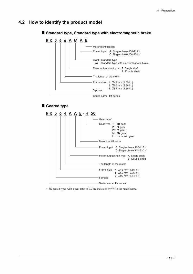
R K 5 6 4 A A E - H 50
Power input A: Single-phase 100-115 V C Single-phase 200-230 V
Motor output shaft type A: Single shaft B Double shaft
The length of the motor
Gear type T: TH gear P: PL gear PS: PS gear N: PN gear H: Harmonic gear
Frame size 4: 42 mm (1.65 in.) 6: 60 mm (2.36 in.) 9: 90 mm (3.54 in.)5-phase
Series name RK series
Gear ratio∗
Motor identification
∗ PS geared types with a gear ratio of 7.2 are indicated by “7” in the model name.
4 Preparation
− 12 −
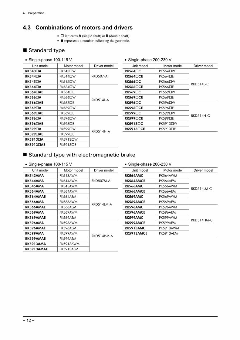
4.3 Combinations of motors and drivers • indicates A (single shaft) or B (double shaft). • represents a number indicating the gear ratio.
Standard type
• Single-phase 100-115 V • Single-phase 200-230 V Unit model Motor model Driver model Unit model Motor model Driver model
RK543 A PK543 W RK564 C PK564 W
RK544 A PK544 W RK564 CE PK564 E
RK545 A PK545 W
RKD507-A
RK566 C PK566 W
RK564 A PK564 W RK566 CE PK566 E
RK564 AE PK564 E RK569 C PK569 W
RK566 A PK566 W RK569 CE PK569 E
RKD514L-C
RK566 AE PK566 E RK596 C PK596 W
RK569 A PK569 W RK596 CE PK596 E
RK569 AE PK569 E
RKD514L-A
RK599 C PK599 W
RK596 A PK596 W RK599 CE PK599 E
RK596 AE PK596 E RK5913 C PK5913 W
RK599 A PK599 W RK5913 CE PK5913 E
RKD514H-C
RK599 AE PK599 E
RK5913 A PK5913 W
RK5913 AE PK5913 E
RKD514H-A
Standard type with electromagnetic brake
• Single-phase 100-115 V • Single-phase 200-230 V Unit model Motor model Driver model Unit model Motor model Driver model
RK543AMA PK543AWM RK564AMC PK564AWM
RK544AMA PK544AWM RK564AMCE PK564AEM
RK545AMA PK545AWM
RKD507M-A
RK566AMC PK566AWM
RK564AMA PK564AWM RK566AMCE PK566AEM
RK564AMAE PK564AEM RK569AMC PK569AWM
RK566AMA PK566AWM RK569AMCE PK569AEM
RKD514LM-C
RK566AMAE PK566AEM RK596AMC PK596AWM
RK569AMA PK569AWM RK596AMCE PK596AEM
RK569AMAE PK569AEM
RKD514LM-A
RK599AMC PK599AWM
RK596AMA PK596AWM RK599AMCE PK599AEM
RK596AMAE PK596AEM RK5913AMC PK5913AWM
RK599AMA PK599AWM RK5913AMCE PK5913AEM
RKD514HM-C
RK599AMAE PK599AEM
RK5913AMA PK5913AWM
RK5913AMAE PK5913AEM
RKD514HM-A
4 Preparation
− 13 −
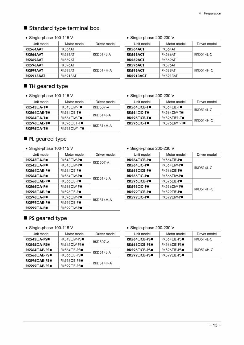
Standard type terminal box
• Single-phase 100-115 V • Single-phase 200-230 V Unit model Motor model Driver model Unit model Motor model Driver model
RK564AAT PK564AT RK564ACT PK564AT
RK566AAT PK566AT RK566ACT PK566AT
RK569AAT PK569AT
RKD514L-A
RK569ACT PK569AT
RKD514L-C
RK596AAT PK596AT RK596ACT PK596AT
RK599AAT PK599AT RK599ACT PK599AT
RK5913AAT PK5913AT
RKD514H-A
RK5913ACT PK5913AT
RKD514H-C
TH geared type
• Single-phase 100-115 V • Single-phase 200-230 V Unit model Motor model Driver model Unit model Motor model Driver model
RK543 A-T PK543 W-T RKD507-A RK564 CE-T PK564 E-T
RK564 AE-T PK564 E-T RK564 C-T PK564 W-T RKD514L-C
RK564 A-T PK564 W-T RKD514L-A
RK596 CE-T PK596 E1-T
RK596 AE-T PK596 E1-T RK596 C-T PK596 W1-T RKD514H-C
RK596 A-T PK596 W1-T RKD514H-A
PL geared type
• Single-phase 100-115 V • Single-phase 200-230 V Unit model Motor model Driver model Unit model Motor model Driver model
RK543 A-P PK543 W-P RK564 CE-P PK564 E-P
RK545 A-P PK545 W-P RKD507-A
RK564 C-P PK564 W-P
RK564 AE-P PK564 E-P RK566 CE-P PK566 E-P
RK564 A-P PK564 W-P RK566 C-P PK566 W-P
RKD514L-C
RK566 AE-P PK566 E-P RK596 CE-P PK596 E-P
RK566 A-P PK566 W-P
RKD514L-A
RK596 C-P PK596 W-P
RK596 AE-P PK596 E-P RK599 CE-P PK599 E-P
RK596 A-P PK596 W-P RK599 C-P PK599 W-P
RKD514H-C
RK599 AE-P PK599 E-P
RK599 A-P PK599 W-P
RKD514H-A
PS geared type
• Single-phase 100-115 V • Single-phase 200-230 V Unit model Motor model Driver model Unit model Motor model Driver model
RK543 A-PS PK543 W-PS RK564 CE-PS PK564 E-PS RKD514L-C
RK545 A-PS PK545 W-PS RKD507-A
RK566 CE-PS PK566 E-PS
RK564 AE-PS PK564 E-PS RK596 CE-PS PK596 E-PS
RK566 AE-PS PK566 E-PS RKD514L-A
RK599 CE-PS PK599 E-PS
RKD514H-C
RK596 AE-PS PK596 E-PS
RK599 AE-PS PK599 E-PS RKD514H-A
4 Preparation
− 14 −
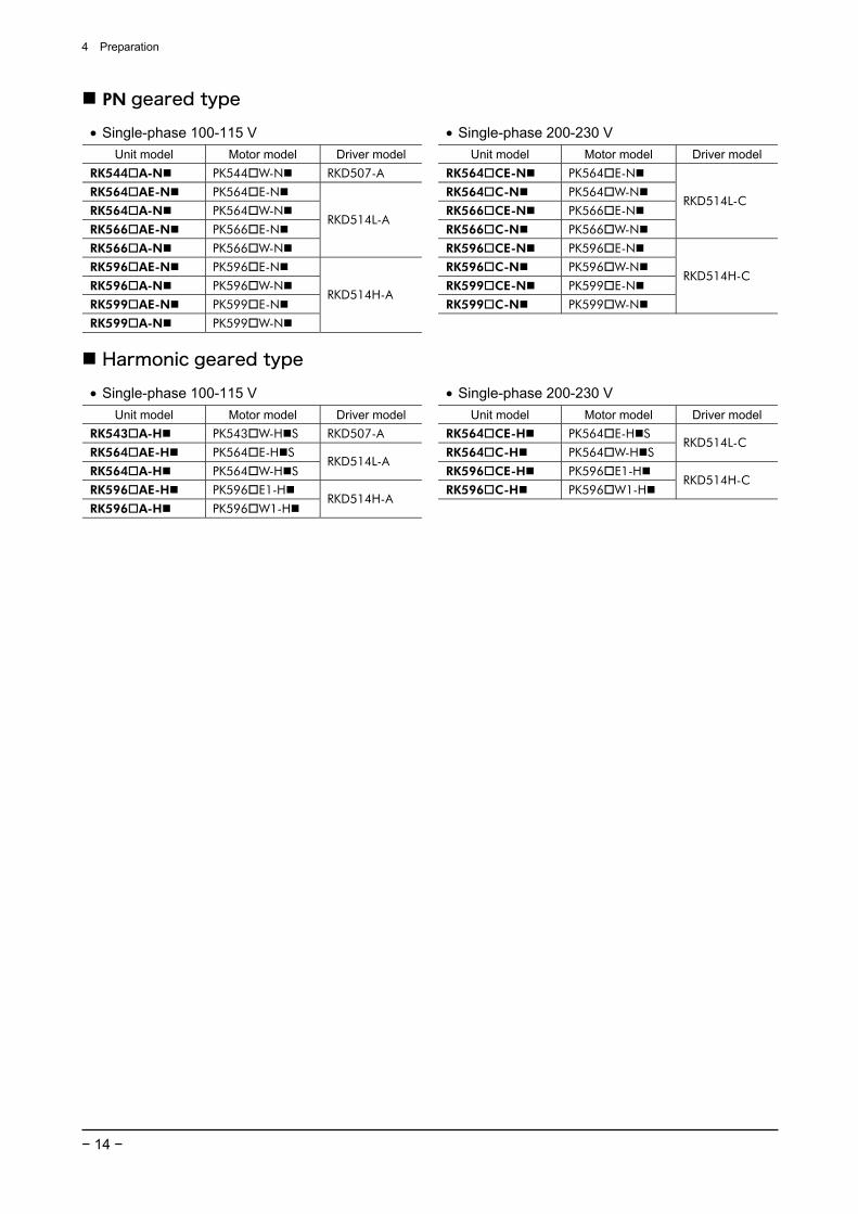
PN geared type
• Single-phase 100-115 V • Single-phase 200-230 V Unit model Motor model Driver model Unit model Motor model Driver model
RK544 A-N PK544 W-N RKD507-A RK564 CE-N PK564 E-N
RK564 AE-N PK564 E-N RK564 C-N PK564 W-N
RK564 A-N PK564 W-N RK566 CE-N PK566 E-N
RK566 AE-N PK566 E-N RK566 C-N PK566 W-N
RKD514L-C
RK566 A-N PK566 W-N
RKD514L-A
RK596 CE-N PK596 E-N
RK596 AE-N PK596 E-N RK596 C-N PK596 W-N
RK596 A-N PK596 W-N RK599 CE-N PK599 E-N
RK599 AE-N PK599 E-N RK599 C-N PK599 W-N
RKD514H-C
RK599 A-N PK599 W-N
RKD514H-A
Harmonic geared type
• Single-phase 100-115 V • Single-phase 200-230 V Unit model Motor model Driver model Unit model Motor model Driver model
RK543 A-H PK543 W-H S RKD507-A RK564 CE-H PK564 E-H S
RK564 AE-H PK564 E-H S RK564 C-H PK564 W-H S RKD514L-C
RK564 A-H PK564 W-H S RKD514L-A
RK596 CE-H PK596 E1-H
RK596 AE-H PK596 E1-H RK596 C-H PK596 W1-H RKD514H-C
RK596 A-H PK596 W1-H RKD514H-A
4 Preparation
− 15 −
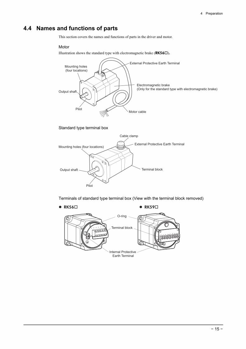
4.4 Names and functions of parts This section covers the names and functions of parts in the driver and motor.
Motor Illustration shows the standard type with electromagnetic brake (RK56 ).
Electromagnetic brake(Only for the standard type with electromagnetic brake)
Motor cable
Mounting holes (four locations)
Output shaft
Pilot
External Protective Earth Terminal
Standard type terminal box
Cable clamp
Terminal block
Mounting holes (four locations)
Output shaft
Pilot
External Protective Earth Terminal
Terminals of standard type terminal box (View with the terminal block removed)
Internal Protective
Earth Terminal
Terminal block
O-ring
RK56 RK59
4 Preparation
− 16 −
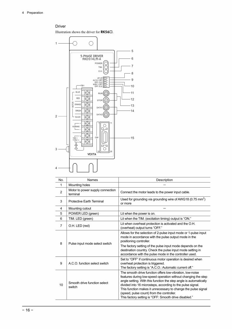
Driver Illustration shows the driver for RK56 .
1
5
6
7
8
9
10
11
12
13
14
15
2
3
4
No. Names Description 1 Mounting holes -
2 Motor to power supply connection terminal Connect the motor leads to the power input cable.
3 Protective Earth Terminal Used for grounding via grounding wire of AWG18 (0.75 mm2) or more
4 Mounting cutout - 5 POWER LED (green) Lit when the power is on. 6 TIM. LED (green) Lit when the TIM. (excitation timing) output is “ON.”
7 O.H. LED (red) Lit when overheat protection is activated and the O.H. (overheat) output turns “OFF.”
8 Pulse input mode select switch
Allows for the selection of 2-pulse input mode or 1-pulse input mode in accordance with the pulse output mode in the positioning controller. The factory setting of the pulse input mode depends on the destination country. Check the pulse input mode setting in accordance with the pulse mode in the controller used.
9 A.C.O. function select switch Set to “OFF” if continuous motor operation is desired when overheat protection is triggered. The factory setting is “A.C.O.: Automatic current off.”
10 Smooth drive function select switch
The smooth drive function offers low-vibration, low-noise features during low-speed operation without changing the step angle setting. With this function the step angle is automatically divided into 16 microsteps, according to the pulse signal. This function makes it unnecessary to change the pulse signal (speed, pulse count) from the controller. This factory setting is “OFF: Smooth drive disabled.”
4 Preparation
− 17 −
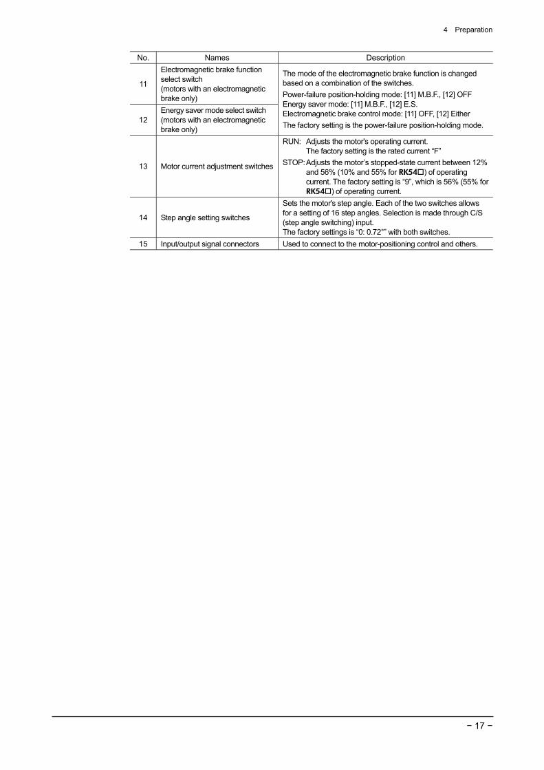
No. Names Description
11
Electromagnetic brake function select switch (motors with an electromagnetic brake only)
12 Energy saver mode select switch (motors with an electromagnetic brake only)
The mode of the electromagnetic brake function is changed based on a combination of the switches. Power-failure position-holding mode: [11] M.B.F., [12] OFF Energy saver mode: [11] M.B.F., [12] E.S. Electromagnetic brake control mode: [11] OFF, [12] Either The factory setting is the power-failure position-holding mode.
13 Motor current adjustment switches
RUN: Adjusts the motor's operating current. The factory setting is the rated current “F”
STOP: Adjusts the motor’s stopped-state current between 12% and 56% (10% and 55% for RK54 ) of operating current. The factory setting is “9”, which is 56% (55% for RK54 ) of operating current.
14 Step angle setting switches
Sets the motor's step angle. Each of the two switches allows for a setting of 16 step angles. Selection is made through C/S (step angle switching) input. The factory settings is “0: 0.72°” with both switches.
15 Input/output signal connectors Used to connect to the motor-positioning control and others.
5 Installation
− 18 −
5 Installation This section covers the environment and method of installing the motor and driver, along with load installation. Also covered in this section are the installation and wiring methods that are in compliance with the relevant EMC Directives.
5.1 Location for installation The motor and driver are designed and manufactured for installation in equipment. Install them in a well-ventilated location that provides easy access for inspection. The location must also satisfy the following conditions: • Inside an enclosure that is installed indoors (provide vent holes) • Operating ambient temperature
Motor: −10 to +50 °C (+14 to +122 °F) (non-freezing) Harmonic geared type: 0 to +40 °C (+32 to +104 °F) (non-freezing)
Driver: 0 to +50 °C (+32 to +122 °F) (non-freezing) • Operating ambient humidity 85% or less (non-condensing) • Operating surrounding atmosphere
Motor, driver: Area that is free of explosive atmosphere or toxic gas (such as sulfuric gas) or liquid
Area free of excessive amount of dust, iron particles or the like Area not subject to splashing water (rains, water droplets), oil (oil droplets) or other liquids
Standard type terminal box: Area that is free of explosive atmosphere or toxic gas (such as sulfuric gas) or liquid
• Area not exposed to direct sun • Area free of excessive salt • Area not subject to continuous vibration or excessive shocks • Area free of excessive electromagnetic noise (from welders, power machinery, etc.) • Area free of radioactive materials, magnetic fields or vacuum
5 Installation
− 19 −
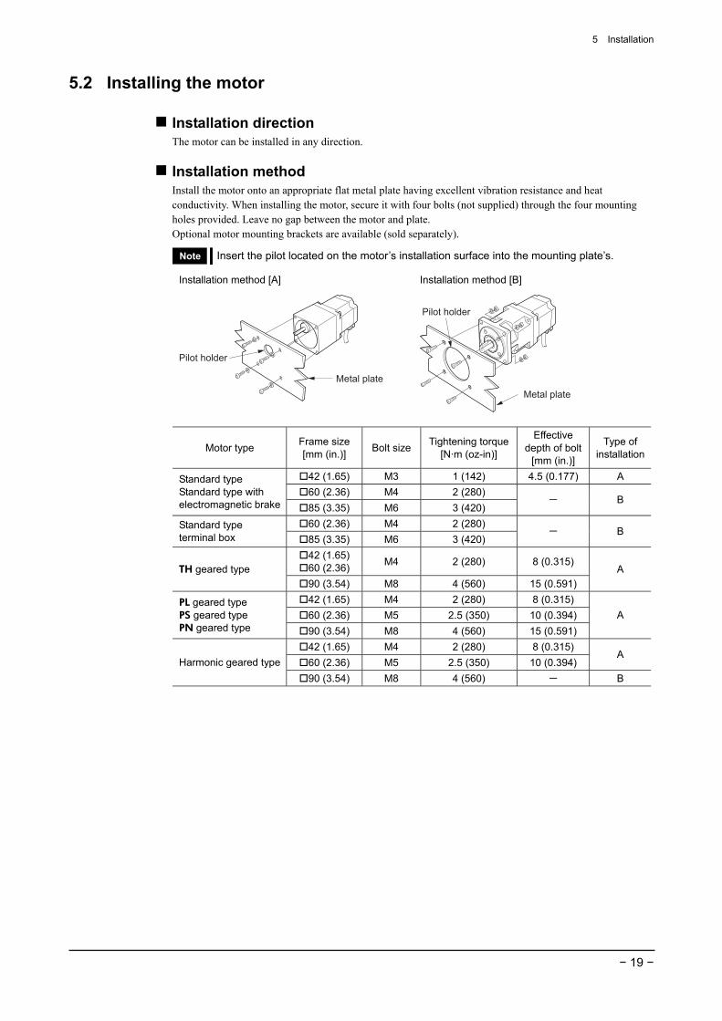
5.2 Installing the motor
Installation direction The motor can be installed in any direction.
Installation method Install the motor onto an appropriate flat metal plate having excellent vibration resistance and heat conductivity. When installing the motor, secure it with four bolts (not supplied) through the four mounting holes provided. Leave no gap between the motor and plate. Optional motor mounting brackets are available (sold separately).
Note Insert the pilot located on the motor’s installation surface into the mounting plate’s.
Installation method [A]
Metal plate
Pilot holder
Installation method [B]
Metal plate
Pilot holder
Motor type Frame size [mm (in.)] Bolt size Tightening torque
[N·m (oz-in)]
Effective depth of bolt
[mm (in.)]
Type of installation
42 (1.65) M3 1 (142) 4.5 (0.177) A 60 (2.36) M4 2 (280)
Standard type Standard type with electromagnetic brake 85 (3.35) M6 3 (420)
- B
60 (2.36) M4 2 (280) Standard type terminal box 85 (3.35) M6 3 (420)
- B
42 (1.65) 60 (2.36) M4 2 (280) 8 (0.315)
TH geared type 90 (3.54) M8 4 (560) 15 (0.591)
A
42 (1.65) M4 2 (280) 8 (0.315) 60 (2.36) M5 2.5 (350) 10 (0.394)
PL geared type PS geared type PN geared type 90 (3.54) M8 4 (560) 15 (0.591)
A
42 (1.65) M4 2 (280) 8 (0.315) 60 (2.36) M5 2.5 (350) 10 (0.394)
A Harmonic geared type
90 (3.54) M8 4 (560) - B
5 Installation
− 20 −
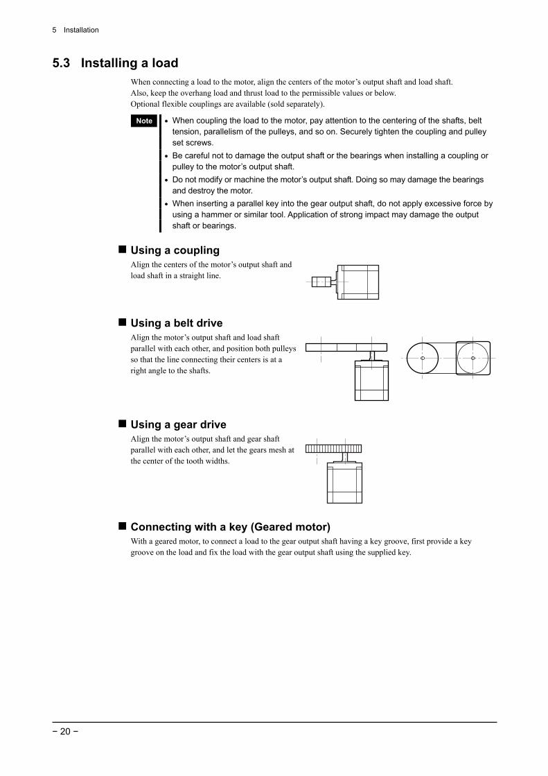
5.3 Installing a load When connecting a load to the motor, align the centers of the motor’s output shaft and load shaft. Also, keep the overhang load and thrust load to the permissible values or below. Optional flexible couplings are available (sold separately).
Note • When coupling the load to the motor, pay attention to the centering of the shafts, belt tension, parallelism of the pulleys, and so on. Securely tighten the coupling and pulley set screws.
• Be careful not to damage the output shaft or the bearings when installing a coupling or pulley to the motor’s output shaft.
• Do not modify or machine the motor’s output shaft. Doing so may damage the bearings and destroy the motor.
• When inserting a parallel key into the gear output shaft, do not apply excessive force by using a hammer or similar tool. Application of strong impact may damage the output shaft or bearings.
Using a coupling Align the centers of the motor’s output shaft and load shaft in a straight line.
Using a belt drive Align the motor’s output shaft and load shaft parallel with each other, and position both pulleys so that the line connecting their centers is at a right angle to the shafts.
Using a gear drive Align the motor’s output shaft and gear shaft parallel with each other, and let the gears mesh at the center of the tooth widths.
Connecting with a key (Geared motor) With a geared motor, to connect a load to the gear output shaft having a key groove, first provide a key groove on the load and fix the load with the gear output shaft using the supplied key.
5 Installation
− 21 −
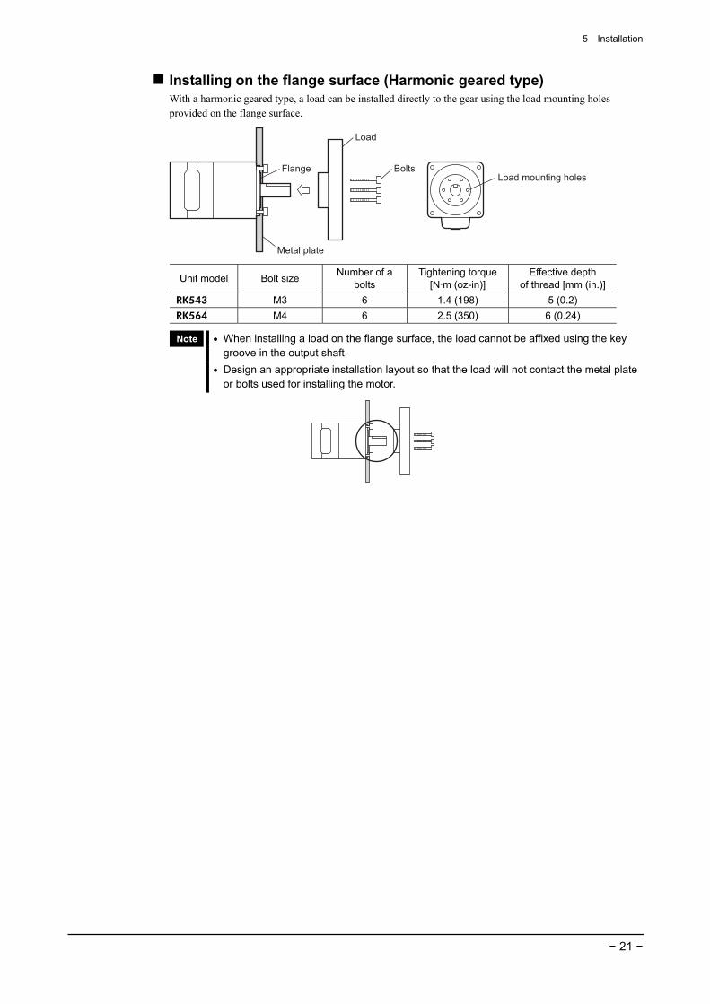
Installing on the flange surface (Harmonic geared type) With a harmonic geared type, a load can be installed directly to the gear using the load mounting holes provided on the flange surface.
Metal plate
Flange Bolts
Load
Load mounting holes
Unit model Bolt size Number of a bolts
Tightening torque [N·m (oz-in)]
Effective depth of thread [mm (in.)]
RK543 M3 6 1.4 (198) 5 (0.2) RK564 M4 6 2.5 (350) 6 (0.24)
Note • When installing a load on the flange surface, the load cannot be affixed using the key groove in the output shaft.
• Design an appropriate installation layout so that the load will not contact the metal plate or bolts used for installing the motor.
5 Installation
− 22 −
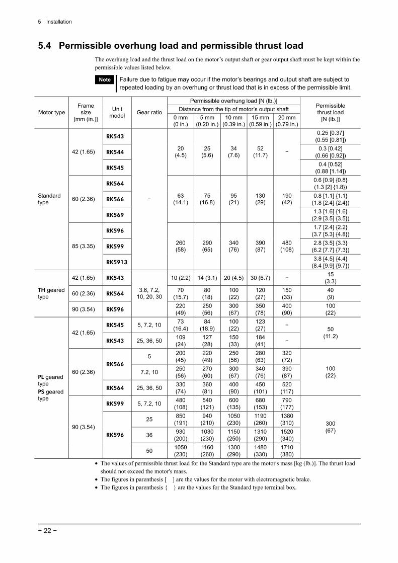
5.4 Permissible overhung load and permissible thrust load The overhung load and the thrust load on the motor’s output shaft or gear output shaft must be kept within the permissible values listed below.
Note Failure due to fatigue may occur if the motor’s bearings and output shaft are subject to repeated loading by an overhung or thrust load that is in excess of the permissible limit.
Permissible overhung load [N (lb.)] Distance from the tip of motor’s output shaft Motor type
Frame size
[mm (in.)]
Unit model Gear ratio
0 mm (0 in.)
5 mm (0.20 in.)
10 mm (0.39 in.)
15 mm (0.59 in.)
20 mm (0.79 in.)
Permissible thrust load
[N (lb.)]
RK543 0.25 [0.37]
(0.55 [0.81])
RK544 0.3 [0.42]
(0.66 [0.92]) 42 (1.65)
RK545
20 (4.5)
25 (5.6)
34 (7.6)
52 (11.7) −
0.4 [0.52] (0.88 [1.14])
RK564 0.6 [0.9] 0.8 (1.3 [2] 1.8)
RK566 0.8 [1.1] 1.1
(1.8 [2.4] 2.4) 60 (2.36)
RK569
63 (14.1)
75 (16.8)
95 (21)
130 (29)
190 (42)
1.3 [1.6] 1.6 (2.9 [3.5] 3.5)
RK596 1.7 [2.4] 2.2
(3.7 [5.3] 4.8)
RK599 2.8 [3.5] 3.3
(6.2 [7.7] 7.3)
Standard type
85 (3.35)
RK5913
−
260 (58)
290 (65)
340 (76)
390 (87)
480 (108)
3.8 [4.5] 4.4 (8.4 [9.9] 9.7)
42 (1.65) RK543 10 (2.2) 14 (3.1) 20 (4.5) 30 (6.7) − 15 (3.3)
60 (2.36) RK564 70
(15.7)80
(18) 100 (22)
120 (27)
150 (33)
40 (9)
TH geared type
90 (3.54) RK596
3.6, 7.2, 10, 20, 30
220 (49)
250 (56)
300 (67)
350 (78)
400 (90)
100 (22)
RK545 5, 7.2, 10 73 (16.4)
84 (18.9)
100 (22)
123 (27) −
42 (1.65) RK543 25, 36, 50 109
(24) 127 (28)
150 (33)
184 (41) −
50 (11.2)
5 200 (45)
220 (49)
250 (56)
280 (63)
320 (72)
RK566 7.2, 10 250
(56) 270 (60)
300 (67)
340 (76)
390 (87) 60 (2.36)
RK564 25, 36, 50 330 (74)
360 (81)
400 (90)
450 (101)
520 (117)
100 (22)
RK599 5, 7.2, 10 480 (108)
540 (121)
600 (135)
680 (153)
790 (177)
25 850 (191)
940 (210)
1050 (230)
1190 (260)
1380 (310)
36 930 (200)
1030 (230)
1150 (250)
1310 (290)
1520 (340)
PL geared type PS geared type
90 (3.54) RK596
50 1050 (230)
1160 (260)
1300 (290)
1480 (330)
1710 (380)
300 (67)
• The values of permissible thrust load for the Standard type are the motor's mass [kg (lb.)]. The thrust load should not exceed the motor's mass.
• The figures in parenthesis [ ] are the values for the motor with electromagnetic brake. • The figures in parenthesis are the values for the Standard type terminal box.
5 Installation
− 23 −
Permissible overhung load [N (lb.)] Distance from the tip of motor’s output shaft Motor type
Frame size
[mm (in.)]
Unit model Gear ratio
0 mm (0 in.)
5 mm (0.20 in.)
10 mm (0.39 in.)
15 mm (0.59 in.)
20 mm (0.79 in.)
Permissible thrust load
[N (lb.)]
42 (1.65) RK544 5, 7.2, 10 100 (22)
120 (27)
150 (33)
190 (42) −
5 200 (45)
220 (49)
250 (56)
280 (63)
320 (72)
RK566 7.2, 10 250
(56) 270 (60)
300 (67)
340 (76)
390 (87) 60 (2.36)
RK564 25, 36, 50 330 (74)
360 (81)
400 (90)
450 (101)
520 (117)
100 (22)
5 480 (108)
520 (117)
550 (123)
580 (130)
620 (139)
RK599 7.2, 10 480
(108) 540
(121) 600
(135) 680
(153) 790
(177)
25 850 (191)
940 (210)
1050 (230)
1110 (240)
1190 (260)
36 930 (200)
1030 (230)
1150 (250)
1220 (270)
1300 (290)
PN geared type
90 (3.54)
RK596
50 1050 (230)
1160 (260)
1300 (290)
1380 (310)
1490 (330)
300 (67)
42 (1.65) RK543 180 (40)
220 (49)
270 (60)
360 (81)
510 (114)
220 (49)
60 (2.36) RK564 320 (72)
370 (83)
440 (99)
550 (123)
720 (162)
450 (101)
Harmonic geared type
90 (3.54) RK596
50, 100
1090 (240)
1150 (250)
1230 (270)
1310 (290)
1410 (310)
1300 (290)
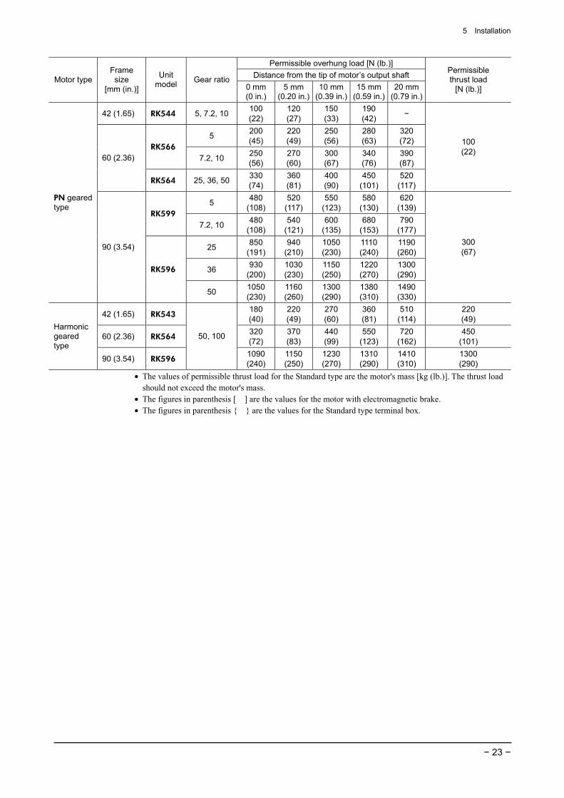
• The values of permissible thrust load for the Standard type are the motor's mass [kg (lb.)]. The thrust load should not exceed the motor's mass.
• The figures in parenthesis [ ] are the values for the motor with electromagnetic brake. • The figures in parenthesis are the values for the Standard type terminal box.
5 Installation
− 24 −
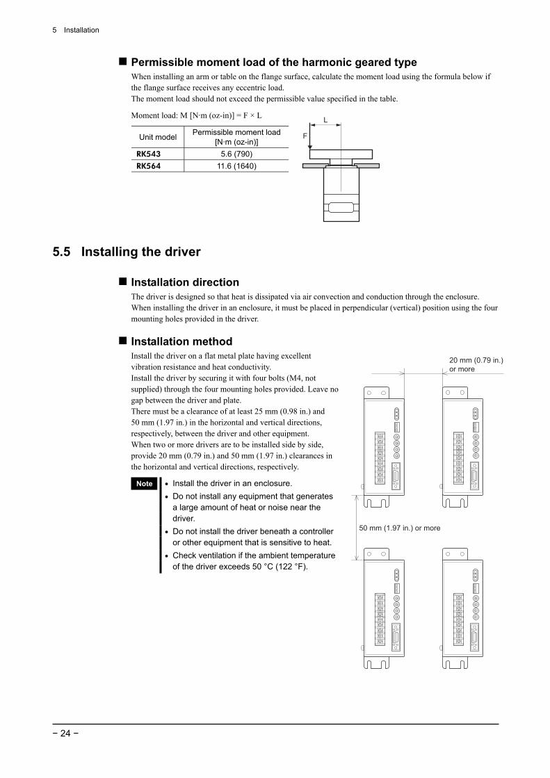
Permissible moment load of the harmonic geared type When installing an arm or table on the flange surface, calculate the moment load using the formula below if the flange surface receives any eccentric load. The moment load should not exceed the permissible value specified in the table.
Moment load: M [N·m (oz-in)] = F × L
Unit model Permissible moment load [N·m (oz-in)]
RK543 5.6 (790) RK564 11.6 (1640)
L
F
5.5 Installing the driver
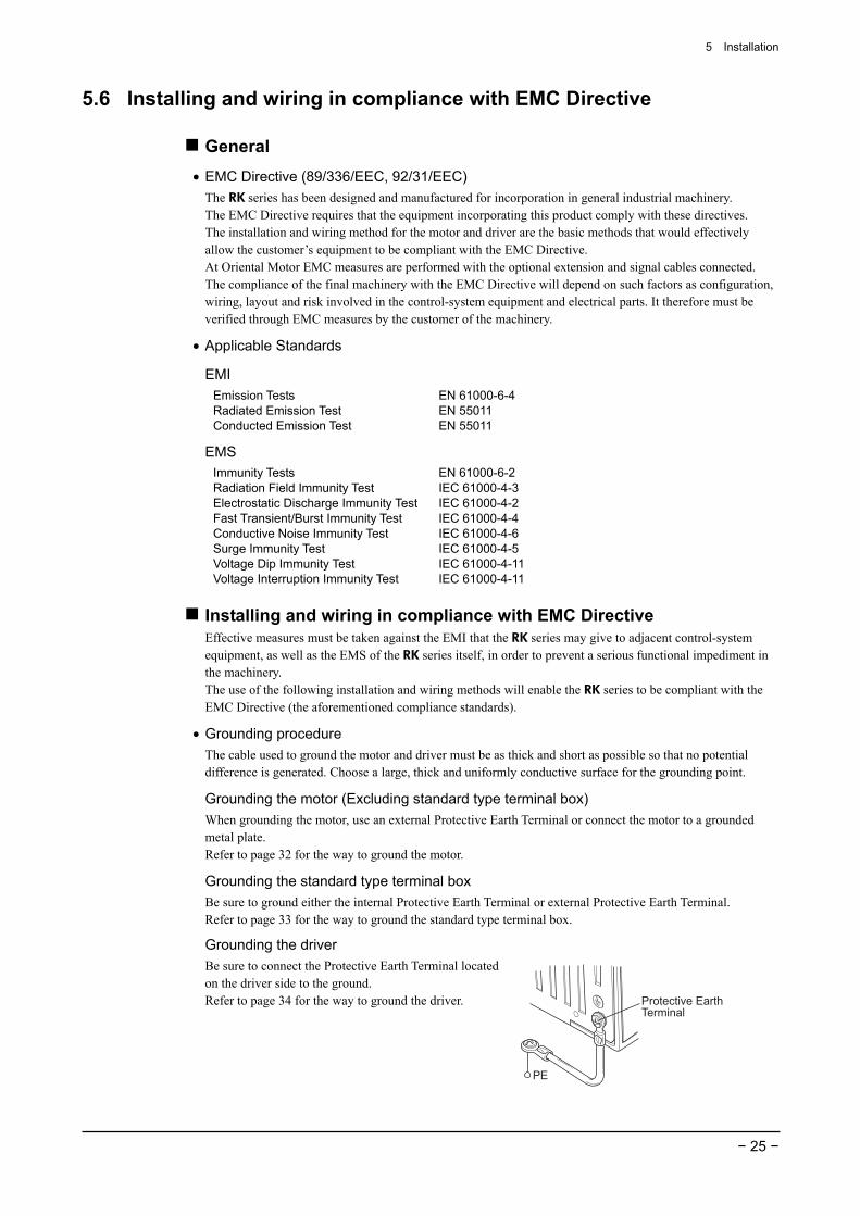
Installation direction The driver is designed so that heat is dissipated via air convection and conduction through the enclosure. When installing the driver in an enclosure, it must be placed in perpendicular (vertical) position using the four mounting holes provided in the driver.
Installation method Install the driver on a flat metal plate having excellent vibration resistance and heat conductivity. Install the driver by securing it with four bolts (M4, not supplied) through the four mounting holes provided. Leave no gap between the driver and plate. There must be a clearance of at least 25 mm (0.98 in.) and 50 mm (1.97 in.) in the horizontal and vertical directions, respectively, between the driver and other equipment. When two or more drivers are to be installed side by side, provide 20 mm (0.79 in.) and 50 mm (1.97 in.) clearances in the horizontal and vertical directions, respectively.
Note • Install the driver in an enclosure. • Do not install any equipment that generates
a large amount of heat or noise near the driver.
• Do not install the driver beneath a controller or other equipment that is sensitive to heat.
• Check ventilation if the ambient temperature of the driver exceeds 50 °C (122 °F).
50 mm (1.97 in.) or more
20 mm (0.79 in.) or more
5 Installation
− 25 −
5.6 Installing and wiring in compliance with EMC Directive
General • EMC Directive (89/336/EEC, 92/31/EEC)
The RK series has been designed and manufactured for incorporation in general industrial machinery. The EMC Directive requires that the equipment incorporating this product comply with these directives. The installation and wiring method for the motor and driver are the basic methods that would effectively allow the customer’s equipment to be compliant with the EMC Directive. At Oriental Motor EMC measures are performed with the optional extension and signal cables connected. The compliance of the final machinery with the EMC Directive will depend on such factors as configuration, wiring, layout and risk involved in the control-system equipment and electrical parts. It therefore must be verified through EMC measures by the customer of the machinery.
• Applicable Standards
EMI Emission Tests Radiated Emission Test Conducted Emission Test
EN 61000-6-4 EN 55011 EN 55011
EMS Immunity Tests Radiation Field Immunity Test Electrostatic Discharge Immunity Test Fast Transient/Burst Immunity Test Conductive Noise Immunity Test Surge Immunity Test Voltage Dip Immunity Test Voltage Interruption Immunity Test
EN 61000-6-2 IEC 61000-4-3 IEC 61000-4-2 IEC 61000-4-4 IEC 61000-4-6 IEC 61000-4-5 IEC 61000-4-11IEC 61000-4-11
Installing and wiring in compliance with EMC Directive Effective measures must be taken against the EMI that the RK series may give to adjacent control-system equipment, as well as the EMS of the RK series itself, in order to prevent a serious functional impediment in the machinery. The use of the following installation and wiring methods will enable the RK series to be compliant with the EMC Directive (the aforementioned compliance standards).
• Grounding procedure The cable used to ground the motor and driver must be as thick and short as possible so that no potential difference is generated. Choose a large, thick and uniformly conductive surface for the grounding point.
Grounding the motor (Excluding standard type terminal box) When grounding the motor, use an external Protective Earth Terminal or connect the motor to a grounded metal plate. Refer to page 32 for the way to ground the motor.
Grounding the standard type terminal box Be sure to ground either the internal Protective Earth Terminal or external Protective Earth Terminal. Refer to page 33 for the way to ground the standard type terminal box.
Grounding the driver Be sure to connect the Protective Earth Terminal located on the driver side to the ground. Refer to page 34 for the way to ground the driver. Protective Earth
Terminal
PE
5 Installation
− 26 −
• Motor cable connection • When the motor cable is extended, use a cable of AWG22 (0.3 mm2) or more with a length of 20 m
(65.6 ft.) or less. Oriental Motor provides optional extension cables. See page 57 for details.
Note Optional extension cables (sold separately) cannot be used with the electromagnetic brake type. To extend the motor cable for the electromagnetic brake type, it is necessary to provide a separate braided-shield wire of AWG22 (0.3 mm2) or more.
• If you are using a standard type terminal box, use a multi-core cable [outer diameter: 7 to 13 mm (0.28 to 0.51 in.)] of at least AWG26 to 16 (0.14 to 1.25 mm2) for the RK56 and at least AWG22 to 16 (0.3 to 1.25 mm2) for the RK59 . We provide an optional motor cable (with protective earth conductor) is available (sold separately). See page 57 for details.
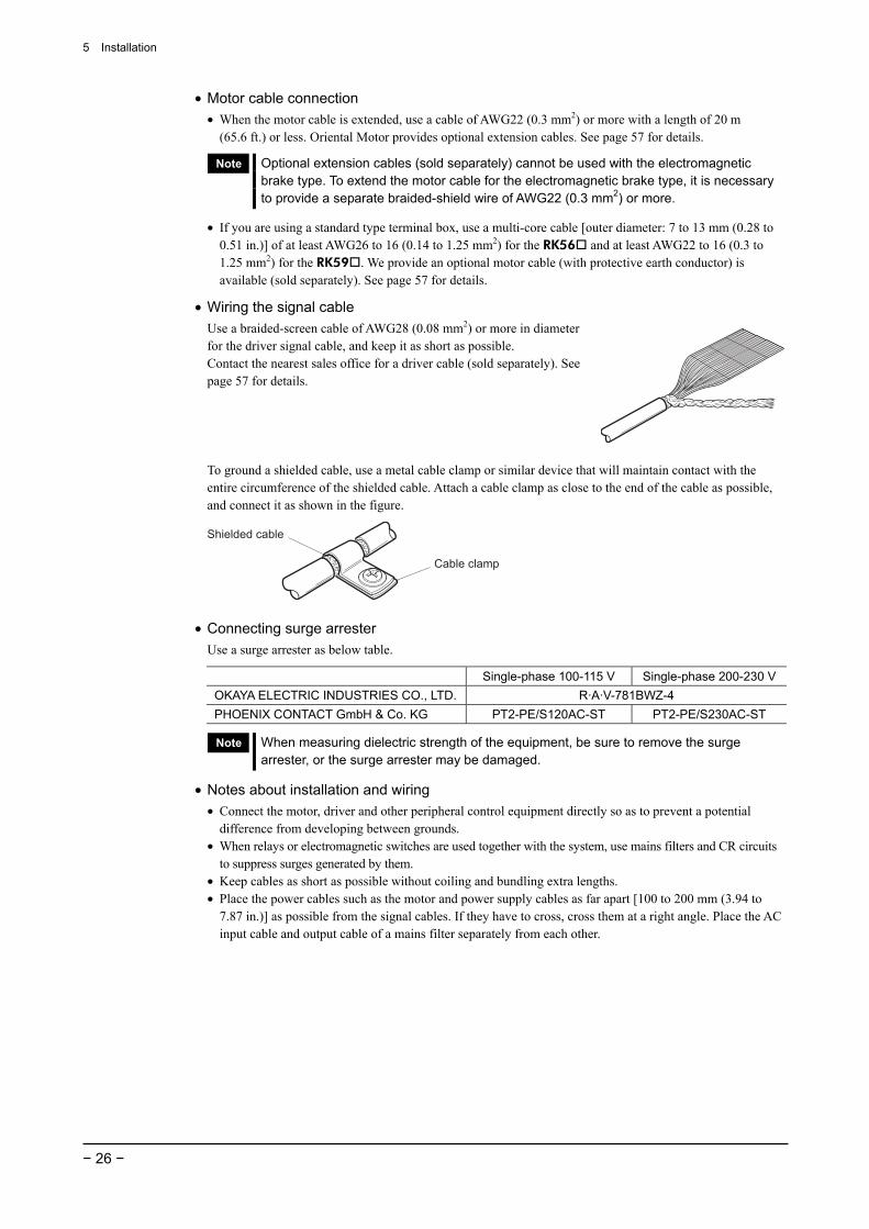
• Wiring the signal cable Use a braided-screen cable of AWG28 (0.08 mm2) or more in diameter for the driver signal cable, and keep it as short as possible. Contact the nearest sales office for a driver cable (sold separately). See page 57 for details.
To ground a shielded cable, use a metal cable clamp or similar device that will maintain contact with the entire circumference of the shielded cable. Attach a cable clamp as close to the end of the cable as possible, and connect it as shown in the figure.
Cable clamp
Shielded cable
• Connecting surge arrester Use a surge arrester as below table.
Single-phase 100-115 V Single-phase 200-230 VOKAYA ELECTRIC INDUSTRIES CO., LTD. R·A·V-781BWZ-4 PHOENIX CONTACT GmbH & Co. KG PT2-PE/S120AC-ST PT2-PE/S230AC-ST
Note When measuring dielectric strength of the equipment, be sure to remove the surge arrester, or the surge arrester may be damaged.
• Notes about installation and wiring • Connect the motor, driver and other peripheral control equipment directly so as to prevent a potential
difference from developing between grounds. • When relays or electromagnetic switches are used together with the system, use mains filters and CR circuits
to suppress surges generated by them. • Keep cables as short as possible without coiling and bundling extra lengths. • Place the power cables such as the motor and power supply cables as far apart [100 to 200 mm (3.94 to
7.87 in.)] as possible from the signal cables. If they have to cross, cross them at a right angle. Place the AC input cable and output cable of a mains filter separately from each other.
5 Installation
− 27 −
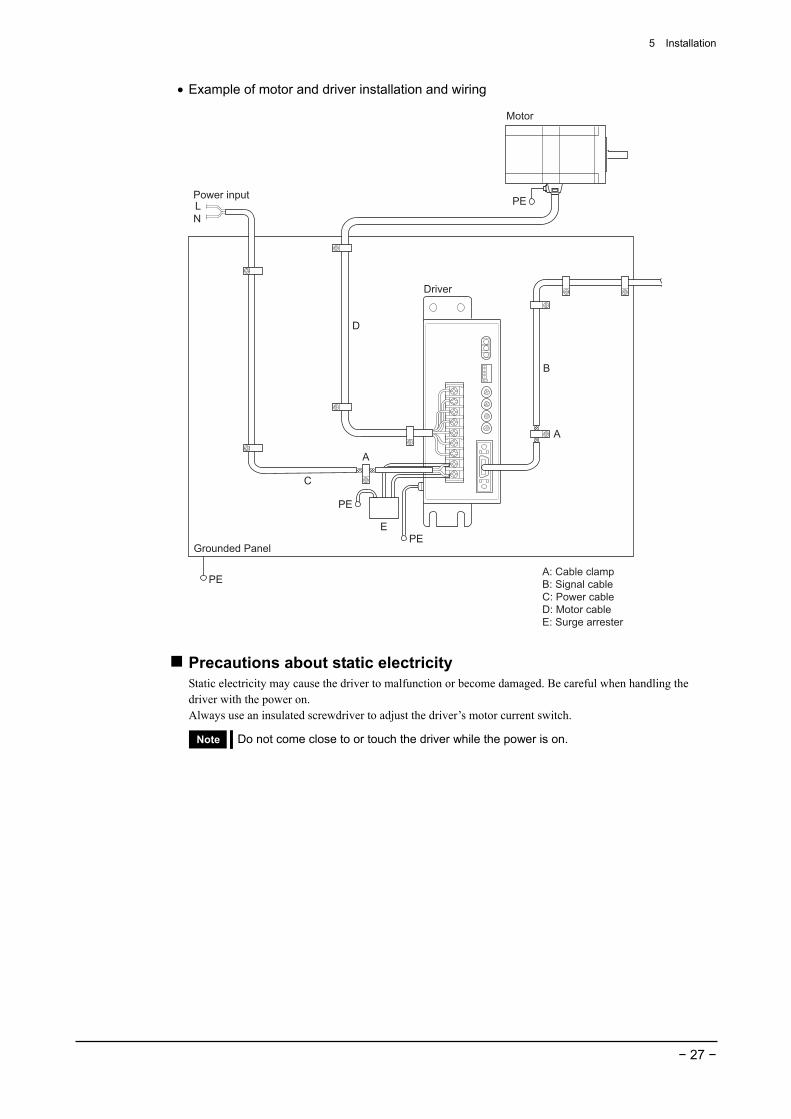
• Example of motor and driver installation and wiring
LN
C
D
B
A
A
A: Cable clampB: Signal cableC: Power cableD: Motor cableE: Surge arrester
Power input
Driver
E
Grounded Panel
Motor
PE
PE
PE
PE
Precautions about static electricity Static electricity may cause the driver to malfunction or become damaged. Be careful when handling the driver with the power on. Always use an insulated screwdriver to adjust the driver’s motor current switch.
Note Do not come close to or touch the driver while the power is on.

6 Connection
− 28 −
6 Connection This section covers the methods and examples of connecting and grounding the driver, motor, power and controller, as well as the input/output signals.
6.1 Connection example for a standard type
BlueRed
Orange
GreenBlack
Connect to TB1
Motor lead wires
5-phase stepping motor
Driver
Power input
CN1 Input and output signal
Connect to controller
PE
PE
Note • The power supply voltage of input signal should be 5 VDC. If the power supply exceeds 5 VDC, connect an external resistor R1 to keep the input current to 7 to 20 mA. Applying a voltage above 5 VDC without using an external resistor will damage the components.Example: When V0 is 24 VDC R1: 1.5 to 2.2 kΩ 0.5 W or more
• Use output signals with a power supply not exceeding 24 VDC and 10 mA. If these specifications are exceeded, the internal elements may be damaged. Check the specification of the connected equipment.
• Be certain the input/output signal cable that connects the driver and controller is as short as possible. The maximum input frequency will decrease as the cable length increases.
• Example of connection with a current sink output circuit
DriverController
+TIM. output 17
-C/S input 8
+C/S input 7
-A.W.OFF input 6
+A.W.OFF input 5
-CCW input 4
+CCW input 3
-CW input 2
+CW input 1
-TIM. output 18
+O.H. output 19
-O.H. output 20
CN1Twisted pair cable
or shielded cable
V0 (+5 to 24 VDC)
V0 (+5 to 24 VDC)
0 V
0 V
0 V
0 V
0 V
R1
R2
R2
R1
R1
R1
Photocoupler input5 VDCInput current 7 to 20 mA
Photocoupler/open collector output24 VDC or lessOutput current 10 mA or less
6 Connection
− 29 −
• Example of connection with a current source output circuit
DriverController
+TIM. output 17
-C/S input 8
+C/S input 7
-A.W.OFF input 6
+A.W.OFF input 5
-CCW input 4
+CCW input 3
-CW input 2
+CW input 1
-TIM. output 18
+O.H. output 19
-O.H. output 20
CN1Twisted pair cable
or shielded cable
R1
R2
R2
R1
R1
R1
Photocoupler input5 VDCInput current 7 to 20 mA
Photocoupler/open collector output24 VDC or lessOutput current 10 mA or less
0 V
V0 (+5 to 24 VDC)
0 V
V0 (+5 to 24 VDC)
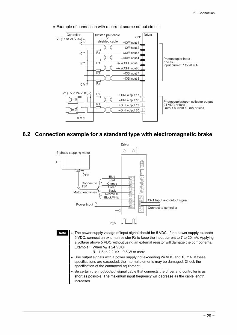
6.2 Connection example for a standard type with electromagnetic brake
CN1 Input and output signal
Connect to controllerPower input
Motor lead wires
Connect to TB1
5-phase stepping motor
Driver
BlueRed
OrangeGreenBlack
Red/White
Black/White
PE
PE
Note • The power supply voltage of input signal should be 5 VDC. If the power supply exceeds 5 VDC, connect an external resistor R1 to keep the input current to 7 to 20 mA. Applying a voltage above 5 VDC without using an external resistor will damage the components.Example: When V0 is 24 VDC R1: 1.5 to 2.2 kΩ 0.5 W or more
• Use output signals with a power supply not exceeding 24 VDC and 10 mA. If these specifications are exceeded, the internal elements may be damaged. Check the specification of the connected equipment.
• Be certain the input/output signal cable that connects the driver and controller is as short as possible. The maximum input frequency will decrease as the cable length increases.
6 Connection
− 30 −
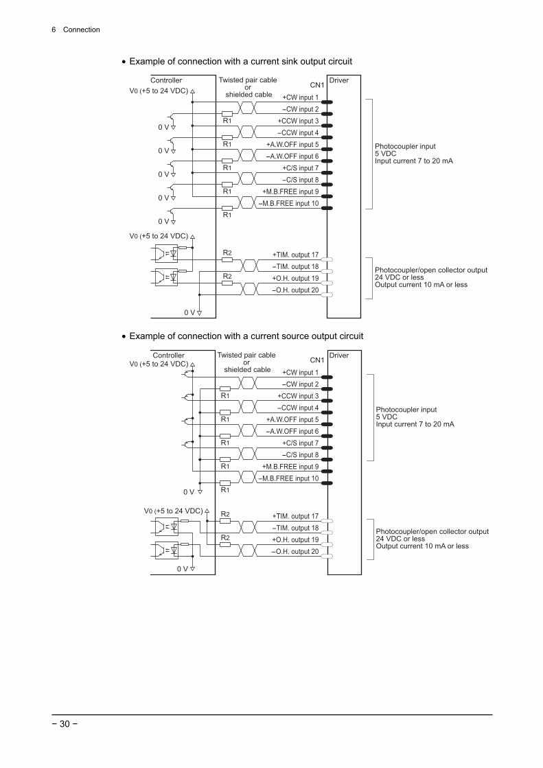
• Example of connection with a current sink output circuit
DriverController
+TIM. output 17
-M.B.FREE input 10
+M.B.FREE input 9
-A.W.OFF input 6
+A.W.OFF input 5
-C/S input 8
+C/S input 7
-CCW input 4
+CCW input 3
-CW input 2
+CW input 1
-TIM. output 18
+O.H. output 19
-O.H. output 20
CN1Twisted pair cable
or shielded cable
0 V
Photocoupler input5 VDCInput current 7 to 20 mA
Photocoupler/open collector output24 VDC or lessOutput current 10 mA or less
0 V
0 V
0 V
0 V
0 V
R2
R2
R1
R1
R1
R1
R1
V0 (+5 to 24 VDC)
V0 (+5 to 24 VDC)
• Example of connection with a current source output circuit
DriverController
+TIM. output 17
-C/S input 8
+C/S input 7
-A.W.OFF input 6
+A.W.OFF input 5
-CCW input 4
+CCW input 3
-CW input 2
+CW input 1
-TIM. output 18
+O.H. output 19
-O.H. output 20
CN1Twisted pair cable
or shielded cable
R1
R2
R2
R1
R1
R1
Photocoupler input5 VDCInput current 7 to 20 mA
Photocoupler/open collector output24 VDC or less Output current 10 mA or less
0 V
V0 (+5 to 24 VDC)
-M.B.FREE input 10
+M.B.FREE input 9
R10 V
V0 (+5 to 24 VDC)

6 Connection
− 31 −
6.3 Connecting the power supply Connect the power cable to the L and N terminals of the motor/power supply terminals located on the driver.
Warning
• The terminals on the driver’s front panel marked with a symbol indicate the presence of high voltage. Do not touch these terminals while the power is on to avoid the risk of fire or electric shock.
• To prevent electric shock, be sure to install the terminal cover (supplied) over the driver’s motor/power supply terminals after making connections.
• Before performing connections, shut off the driver power and wait at least 15 seconds in order to avoid the risk of electric shock.
Note • Furnish a power supply capable of supplying adequate driver input current. If the
current capacity is insufficient, the transformer may be damaged, or the motor may run erratically due to a drop in torque.
• Do not run the driver’s power cable through a conduit containing other power lines or motor cables.
For single-phase 100-115 V Connect the live side of the single-phase 100-115 V power cable to the L terminal and the neutral side to the N terminal. Use a power supply capable of supplying the current capacity as shown below.
Model Current capacity RK54 Single-phase 100-115 V±15% 1 A or more RK56 RK59
Single-phase 100-115 V±15% 4.5 A or more
Single-phase 100-115 V
Live side
Neutral side
For single-phase 200-230 V Connect the live side of the single-phase 200-230 V power cable to the L terminal and the neutral side to the N terminal. Use a power supply capable of supplying single-phase 200−230 V+10%
-15% at 3.5 A or greater.
Single-phase 200-230 V
Live side
Neutral side
Terminal screw size and lead wire size for power connection Screw size: M3 Tightening torque: 0.8 N·m (113 oz-in) Applicable minimum lead wire size: AWG22 (0.3 mm2)
Appropriate crimp terminal
3.2 (0.13) or moreØ3.2 (Ø0.13) or more
6.2
(0
.24
) o
r le
ss
9 (0.35) or more
[Unit: mm (in.)]
9 (0.35) or more6.2
(0
.24
) o
r le
ss
6 Connection
− 32 −
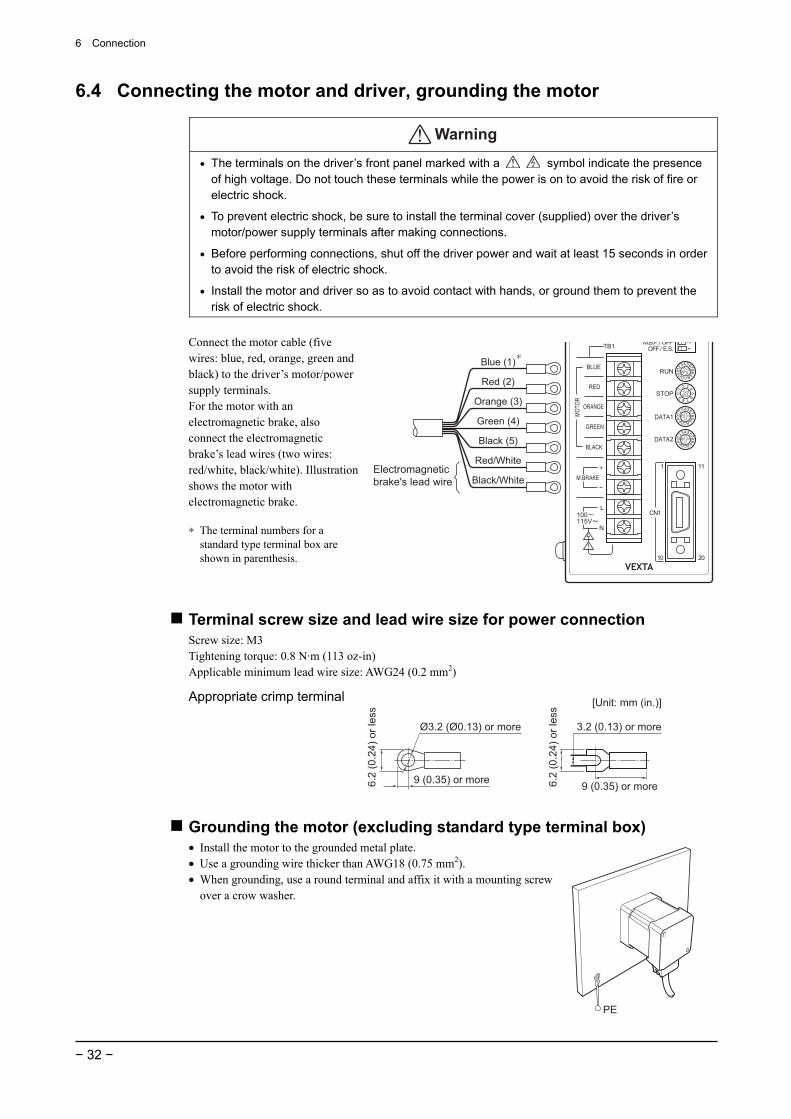
6.4 Connecting the motor and driver, grounding the motor
Warning
• The terminals on the driver’s front panel marked with a symbol indicate the presence of high voltage. Do not touch these terminals while the power is on to avoid the risk of fire or electric shock.
• To prevent electric shock, be sure to install the terminal cover (supplied) over the driver’s motor/power supply terminals after making connections.
• Before performing connections, shut off the driver power and wait at least 15 seconds in order to avoid the risk of electric shock.
• Install the motor and driver so as to avoid contact with hands, or ground them to prevent the risk of electric shock.
Connect the motor cable (five wires: blue, red, orange, green and black) to the driver’s motor/power supply terminals. For the motor with an electromagnetic brake, also connect the electromagnetic brake’s lead wires (two wires: red/white, black/white). Illustration shows the motor with electromagnetic brake. ∗ The terminal numbers for a
standard type terminal box are shown in parenthesis.
Black/White
Red/White
Blue (1)
Red (2)
Orange (3)
Black (5)
Green (4)
Electromagnetic brake's lead wire
∗
Terminal screw size and lead wire size for power connection Screw size: M3 Tightening torque: 0.8 N·m (113 oz-in) Applicable minimum lead wire size: AWG24 (0.2 mm2)
Appropriate crimp terminal
3.2 (0.13) or moreØ3.2 (Ø0.13) or more
6.2
(0
.24
) o
r le
ss
9 (0.35) or more
[Unit: mm (in.)]
9 (0.35) or more6.2
(0
.24
) o
r le
ss
Grounding the motor (excluding standard type terminal box) • Install the motor to the grounded metal plate. • Use a grounding wire thicker than AWG18 (0.75 mm2). • When grounding, use a round terminal and affix it with a mounting screw
over a crow washer.
PE
6 Connection
− 33 −
RK56 E, RK59 E • Be sure to ground the external Protective Earth Terminal (screw size: M4).• Use a grounding wire thicker than AWG18 (0.75 mm2).
PE
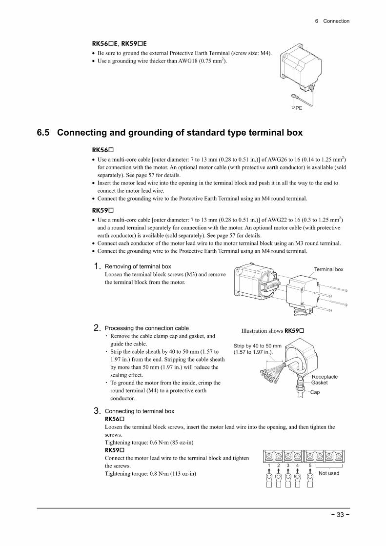
6.5 Connecting and grounding of standard type terminal box
RK56 • Use a multi-core cable [outer diameter: 7 to 13 mm (0.28 to 0.51 in.)] of AWG26 to 16 (0.14 to 1.25 mm2)
for connection with the motor. An optional motor cable (with protective earth conductor) is available (sold separately). See page 57 for details.
• Insert the motor lead wire into the opening in the terminal block and push it in all the way to the end to connect the motor lead wire.
• Connect the grounding wire to the Protective Earth Terminal using an M4 round terminal.
RK59 • Use a multi-core cable [outer diameter: 7 to 13 mm (0.28 to 0.51 in.)] of AWG22 to 16 (0.3 to 1.25 mm2)
and a round terminal separately for connection with the motor. An optional motor cable (with protective earth conductor) is available (sold separately). See page 57 for details.
• Connect each conductor of the motor lead wire to the motor terminal block using an M3 round terminal. • Connect the grounding wire to the Protective Earth Terminal using an M4 round terminal.
1. Removing of terminal box Loosen the terminal block screws (M3) and remove the terminal block from the motor.
Terminal box
2. Processing the connection cable ・ Remove the cable clamp cap and gasket, and
guide the cable. ・ Strip the cable sheath by 40 to 50 mm (1.57 to
1.97 in.) from the end. Stripping the cable sheath by more than 50 mm (1.97 in.) will reduce the sealing effect.
・ To ground the motor from the inside, crimp the round terminal (M4) to a protective earth conductor.
Illustration shows RK59
Strip by 40 to 50 mm (1.57 to 1.97 in.).
ReceptacleGasket
Cap
3. Connecting to terminal box RK56 Loosen the terminal block screws, insert the motor lead wire into the opening, and then tighten the screws. Tightening torque: 0.6 N·m (85 oz-in) RK59 Connect the motor lead wire to the terminal block and tighten the screws. Tightening torque: 0.8 N·m (113 oz-in) Not used
1 2 3 4 5
6 Connection
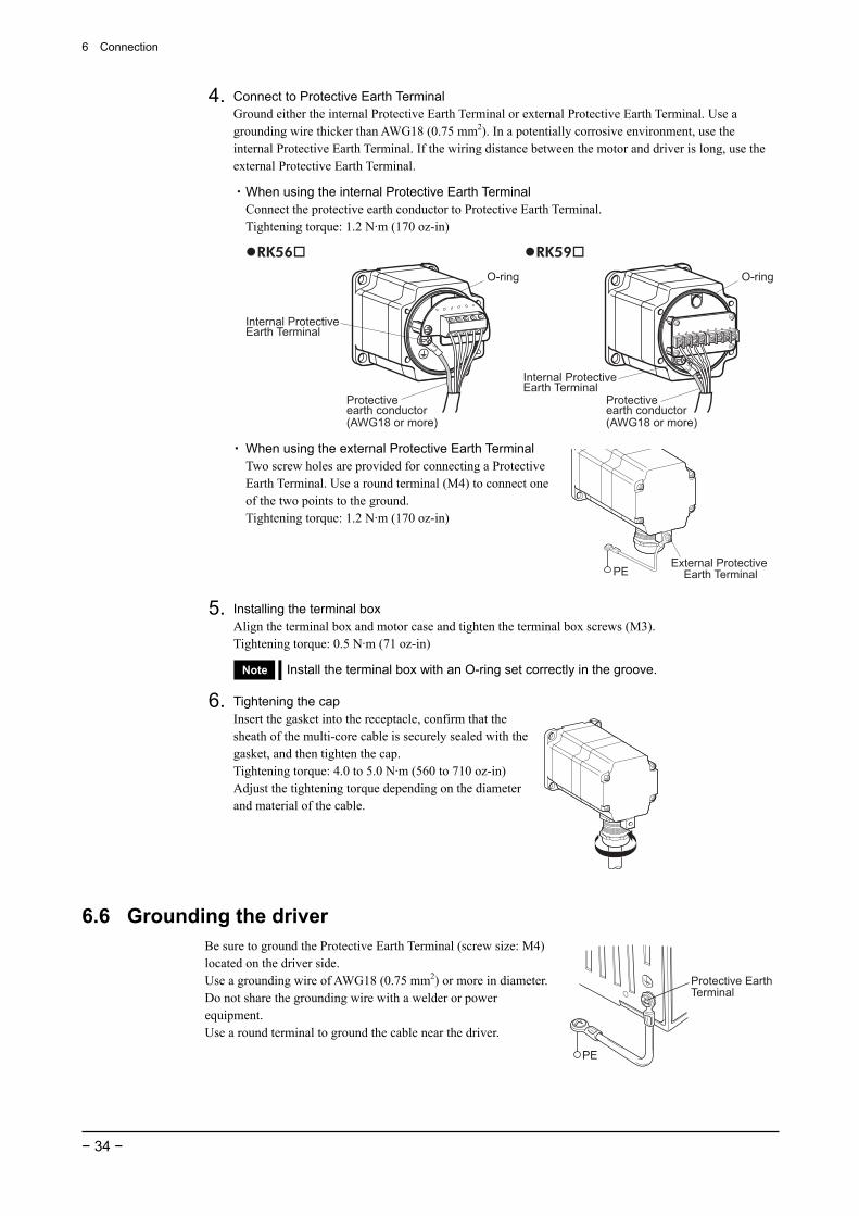
− 34 −
4. Connect to Protective Earth Terminal Ground either the internal Protective Earth Terminal or external Protective Earth Terminal. Use a grounding wire thicker than AWG18 (0.75 mm2). In a potentially corrosive environment, use the internal Protective Earth Terminal. If the wiring distance between the motor and driver is long, use the external Protective Earth Terminal.
・ When using the internal Protective Earth Terminal Connect the protective earth conductor to Protective Earth Terminal. Tightening torque: 1.2 N·m (170 oz-in)
Protective earth conductor(AWG18 or more)
Protective earth conductor(AWG18 or more)
Internal Protective Earth Terminal
Internal Protective Earth Terminal
RK56 RK59
O-ring O-ring
・ When using the external Protective Earth Terminal Two screw holes are provided for connecting a Protective Earth Terminal. Use a round terminal (M4) to connect one of the two points to the ground. Tightening torque: 1.2 N·m (170 oz-in)
External Protective Earth TerminalPE
5. Installing the terminal box Align the terminal box and motor case and tighten the terminal box screws (M3). Tightening torque: 0.5 N·m (71 oz-in)
Note Install the terminal box with an O-ring set correctly in the groove.
6. Tightening the cap
Insert the gasket into the receptacle, confirm that the sheath of the multi-core cable is securely sealed with the gasket, and then tighten the cap. Tightening torque: 4.0 to 5.0 N·m (560 to 710 oz-in) Adjust the tightening torque depending on the diameter and material of the cable.
6.6 Grounding the driver Be sure to ground the Protective Earth Terminal (screw size: M4) located on the driver side. Use a grounding wire of AWG18 (0.75 mm2) or more in diameter. Do not share the grounding wire with a welder or power equipment. Use a round terminal to ground the cable near the driver.
Protective Earth Terminal
PE
6 Connection
− 35 −
6.7 Connecting the input/output signals
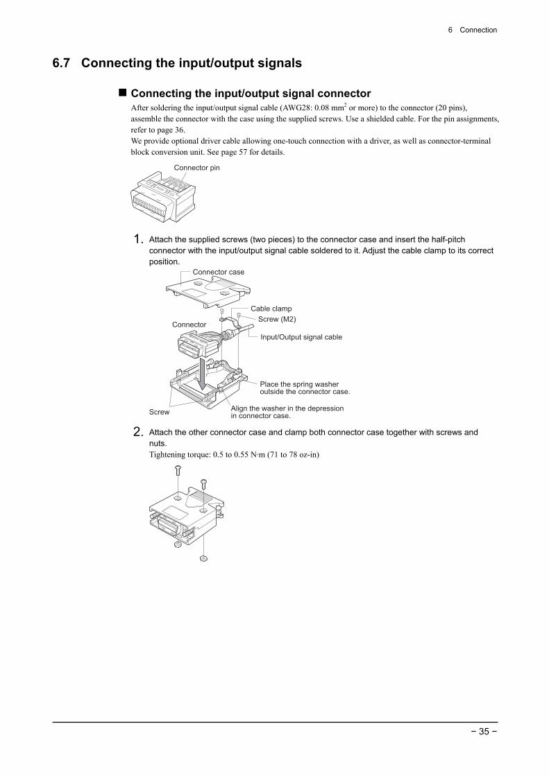
Connecting the input/output signal connector After soldering the input/output signal cable (AWG28: 0.08 mm2 or more) to the connector (20 pins), assemble the connector with the case using the supplied screws. Use a shielded cable. For the pin assignments, refer to page 36. We provide optional driver cable allowing one-touch connection with a driver, as well as connector-terminal block conversion unit. See page 57 for details.
Connector pin
1. Attach the supplied screws (two pieces) to the connector case and insert the half-pitch connector with the input/output signal cable soldered to it. Adjust the cable clamp to its correct position.
Input/Output signal cable
Cable clamp
Screw
Connector case
Connector
Place the spring washer outside the connector case.
Screw (M2)
Align the washer in the depression in connector case.
2. Attach the other connector case and clamp both connector case together with screws and nuts. Tightening torque: 0.5 to 0.55 N·m (71 to 78 oz-in)
6 Connection
− 36 −
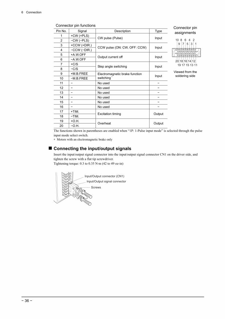
Connector pin functions Pin No. Signal Description Type
1 +CW (+PLS) 2 −CW (−PLS)
CW pulse (Pulse) Input
3 +CCW (+DIR.) 4 −CCW (−DIR.)
CCW pulse (ON: CW, OFF: CCW) Input
5 +A.W.OFF 6 −A.W.OFF
Output current off Input
7 +C/S 8 −C/S
Step angle switching Input
9 +M.B.FREE 10 −M.B.FREE
Electromagnetic brake function switching ∗ Input
11 − No used − 12 − No used − 13 − No used − 14 − No used − 15 − No used − 16 − No used − 17 +TIM. 18 −TIM.
Excitation timing Output
19 +O.H. 20 −O.H.
Overheat Output
Connector pin assignments
1
2
3
4
5
6
7
8
9
10
20
19
18
17
16
15
14
13
12
11
Viewed from the soldering side
The functions shown in parentheses are enabled when “1P: 1-Pulse input mode” is selected through the pulse input mode select switch. ∗ Motors with an electromagnetic brake only
Connecting the input/output signals Insert the input/output signal connector into the input/output signal connector CN1 on the driver side, and tighten the screw with a flat tip screwdriver. Tightening torque: 0.3 to 0.35 N·m (42 to 49 oz-in)
Input/Output signal connector
Input/Output connector (CN1)
Screws
6 Connection
− 37 −
6.8 About input/output signals
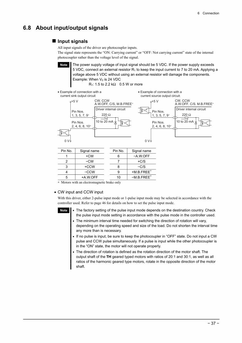
Input signals All input signals of the driver are photocoupler inputs. The signal state represents the “ON: Carrying current” or “OFF: Not carrying current” state of the internal photocoupler rather than the voltage level of the signal.
Note The power supply voltage of input signal should be 5 VDC. If the power supply exceeds 5 VDC, connect an external resistor R1 to keep the input current to 7 to 20 mA. Applying a voltage above 5 VDC without using an external resistor will damage the components. Example: When V0 is 24 VDC R1: 1.5 to 2.2 kΩ 0.5 W or more
CW, CCWA.W.OFF, C/S, M.B.FREE∗
Pin Nos.1, 3, 5, 7, 9∗
Pin Nos.2, 4, 6, 8, 10∗
Driver internal circuit
10 to 20 mA
+5 V
0 V 0 V
+5 V
220 Ω
CW CCWA.W.OFF C/S M.B.FREE∗
Pin Nos.1, 3, 5, 7, 9∗
Pin Nos.2, 4, 6, 8, 10∗
Driver internal circuit
• Example of connection with a current sink output circuit
• Example of connection with a current source output circui
10 to 20 mA
220 Ω
Pin No. Signal name Pin No. Signal name 1 +CW 6 −A.W.OFF 2 −CW 7 +C/S 3 +CCW 8 −C/S 4 −CCW 9 +M.B.FREE∗ 5 +A.W.OFF 10 −M.B.FREE∗
∗ Motors with an electromagnetic brake only
• CW input and CCW input With this driver, either 2-pulse input mode or 1-pulse input mode may be selected in accordance with the controller used. Refer to page 46 for details on how to set the pulse input mode.
Note • The factory setting of the pulse input mode depends on the destination country. Check the pulse input mode setting in accordance with the pulse mode in the controller used.
• The minimum interval time needed for switching the direction of rotation will vary, depending on the operating speed and size of the load. Do not shorten the interval time any more than is necessary.
• If no pulse is input, be sure to keep the photocoupler in “OFF” state. Do not input a CW pulse and CCW pulse simultaneously. If a pulse is input while the other photocoupler is in the “ON” state, the motor will not operate properly.
• The direction of rotation is defined as the rotation direction of the motor shaft. The output shaft of the TH geared typed motors with ratios of 20:1 and 30:1, as well as all ratios of the harmonic geared type motors, rotate in the opposite direction of the motor shaft.
6 Connection
− 38 −
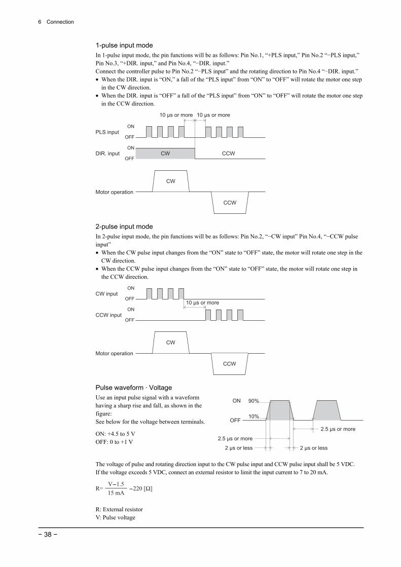
1-pulse input mode In 1-pulse input mode, the pin functions will be as follows: Pin No.1, “+PLS input,” Pin No.2 “−PLS input,” Pin No.3, “+DIR. input,” and Pin No.4, “−DIR. input.” Connect the controller pulse to Pin No.2 “−PLS input” and the rotating direction to Pin No.4 “−DIR. input.” • When the DIR. input is “ON,” a fall of the “PLS input” from “ON” to “OFF” will rotate the motor one step
in the CW direction. • When the DIR. input is “OFF” a fall of the “PLS input” from “ON” to “OFF” will rotate the motor one step
in the CCW direction.
CW
CCW
PLS input
10 µs or more 10 µs or more
DIR. input
ON
OFF
ON
OFF
Motor operation
CW CCW
2-pulse input mode In 2-pulse input mode, the pin functions will be as follows: Pin No.2, “−CW input” Pin No.4, “−CCW pulse input” • When the CW pulse input changes from the “ON” state to “OFF” state, the motor will rotate one step in the
CW direction. • When the CCW pulse input changes from the “ON” state to “OFF” state, the motor will rotate one step in
the CCW direction.
CW input
CCW input
ON
ON
OFF
OFF
Motor operation
10 µs or more
CW
CCW
Pulse waveform · Voltage Use an input pulse signal with a waveform having a sharp rise and fall, as shown in the figure: See below for the voltage between terminals.
ON: +4.5 to 5 V OFF: 0 to +1 V
ON
OFF
90%
10%
2.5 µs or more
2.5 µs or more
2 µs or less 2 µs or less
The voltage of pulse and rotating direction input to the CW pulse input and CCW pulse input shall be 5 VDC. If the voltage exceeds 5 VDC, connect an external resistor to limit the input current to 7 to 20 mA.
R= -220 [Ω]
V-1.5
15 mA
R: External resistor V: Pulse voltage
6 Connection
− 39 −
• A.W.OFF (All windings off) input Use this signal only when the motor’s output shaft must be mechanically rotated for position adjustment.
Warning
Do not turn the A.W.OFF input to “ON” while the motor is operating. The motor will stop and lose its holding ability. As a result, the load will fall and may cause injury or damage to equipment.
• When the A.W.OFF input is turned “ON,” the driver will shut off the output current and the motor will lose its excitation holding torque. This, however, will allow you to adjust the load position manually.
• When the A.W.OFF input is turned “OFF,” the driver will turn the output current to “ON” again and the motor’s excitation holding torque will be restored. The A.W.OFF input must be “OFF” when operating the motor.
Note • Normally, keep the A.W.OFF input in the “OFF” state or leave it disconnected. • Do not input pulse signals immediately after switching the A.W.OFF signal to “OFF,”
since doing so will affect the motor’s starting characteristics. As a general rule, wait at least 150 ms before inputting a pulse signal.
• C/S (step angle switching) input Selects and switches between the two step angle switches (DATA1 and DATA2). For instance, if “DATA1: 0.72°” and “DATA2: 0.072°” have been selected, this signal can switch between the 0.72°/step rotation and 0.072°/step rotation. For the values of step angles set through DATA1 and DATA2, refer to 7.1 “Step angle” on page 44. • Turning the C/S input to “OFF” will select/switch to “DATA1.” • Turning the C/S input to “ON” will select/switch to “DATA2.”
Note • Do not switch the C/S input while the motor is operating, or the motor may misstep and stop or cause an offset in position.
• If the C/S input must be used to switch the step angles after the driver power has been turned on, do so while the driver’s TIM. (timing) output is “ON” and the motor is at rest. Switching the C/S input under any other condition may disable the TIM. output and TIM. LED ON/OFF functions. For further information on the TIM. output, refer to page 40.
• M.B.FREE (electromagnetic brake free) input (applicable only to motors with an electromagnetic brake) Setting the electromagnetic brake function select switch (refer to page 48) to the “OFF” side allows control over releasing and holding the electromagnetic brake via the M.B.FREE input. To operate the motor, be sure to release the electromagnetic brake by turning the M.B.FREE input to “ON.” • Setting the M.B.FREE input to “ON” causes the driver to “release” the electromagnetic brake and allow
motor operation. • Setting the M.B.FREE input to “OFF” causes the driver to “hold” the electromagnetic brake.
Note An abrupt fluctuation in the load may cause the motor to misstep∗ during operation, start-up or standstill. The motor is not equipped with a function that triggers the electromagnetic brake upon the occurrence of a misstep. Therefore, when using the motor for an application involving vertical travel, perform sufficient test runs by conducting a test using the actual load to make sure that the motor is capable of driving the load without fail.
∗ Misstep: The term “misstep” refers to a condition in which the motor undergoes a rapid speed change or receives an excessive load and consequently stops or causes an offset in position due to its inability to turn synchronously with the pulse input. To hold the load in position while in the energy saver mode, verify that the load is within the range that can be held in position with the static friction torque of the electromagnetic brake.
6 Connection
− 40 −
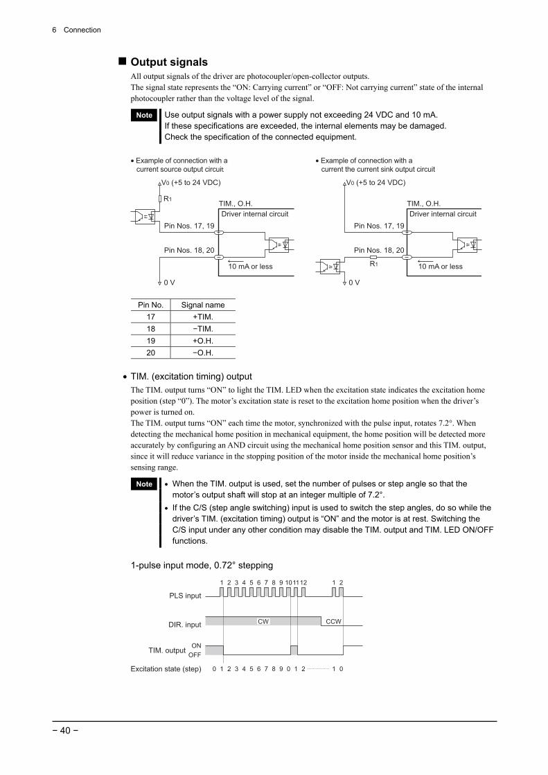
Output signals All output signals of the driver are photocoupler/open-collector outputs. The signal state represents the “ON: Carrying current” or “OFF: Not carrying current” state of the internal photocoupler rather than the voltage level of the signal.
Note Use output signals with a power supply not exceeding 24 VDC and 10 mA. If these specifications are exceeded, the internal elements may be damaged. Check the specification of the connected equipment.
TIM., O.H.
Pin Nos. 17, 19
Pin Nos. 18, 20
Driver internal circuit
• Example of connection with a current the current sink output circuit
• Example of connection with a current source output circui
10 mA or less
V0 (+5 to 24 VDC)
0 V
R1
Driver internal circuit
V0 (+5 to 24 VDC)
TIM., O.H.
Pin Nos. 17, 19
Pin Nos. 18, 20
10 mA or less
0 V
R1
Pin No. Signal name 17 +TIM. 18 −TIM. 19 +O.H. 20 −O.H.
• TIM. (excitation timing) output The TIM. output turns “ON” to light the TIM. LED when the excitation state indicates the excitation home position (step “0”). The motor’s excitation state is reset to the excitation home position when the driver’s power is turned on. The TIM. output turns “ON” each time the motor, synchronized with the pulse input, rotates 7.2°. When detecting the mechanical home position in mechanical equipment, the home position will be detected more accurately by configuring an AND circuit using the mechanical home position sensor and this TIM. output, since it will reduce variance in the stopping position of the motor inside the mechanical home position’s sensing range.
Note • When the TIM. output is used, set the number of pulses or step angle so that the motor’s output shaft will stop at an integer multiple of 7.2°.
• If the C/S (step angle switching) input is used to switch the step angles, do so while the driver’s TIM. (excitation timing) output is “ON” and the motor is at rest. Switching the C/S input under any other condition may disable the TIM. output and TIM. LED ON/OFF functions.
1-pulse input mode, 0.72° stepping
TIM. output
1 20 3 4 5 6 7 8 9 0 1 2 1 0Excitation state (step)
ON
OFF
PLS input
1 2 3 4 5 6 7 8 9 101112 1 2
DIR. input CCWCW

6 Connection
− 41 −
2-pulse input mode, 0.72° stepping
CW pulse input
CCW pulse input
TIM. output
1 2 3 4 5 6 7 8 9 101112
1 2
1 20 3 4 5 6 7 8 9 0 1 2 1 0Excitation state (step)
ON
OFF
Example of TIM. output not turning “ON” The figure below shows a condition in which the motor operates for a period of nine pulses at a step angle of 0.072°/step, and then operates for one pulse at a step angle of 0.72°/step. The TIM. output will not switch to “ON” once the excitation origin is exceeded, as shown in the figure.
0°
0.72°
-0.72° 0.72°
0.072°
The motor is rotated over
9 pulse at a step angle
of 0.072°.
The motor is rotated over
1 pulse at a step angle
of 0.72°.
Excitation home position
• O.H. (overheat) output The O.H. output remains “ON” when the driver is operating normally, then turns “OFF” to light the O.H. LED when overheat protection is triggered. Check the operating conditions of the motor and the ventilation within the enclosure when overheat protection is triggered.
Warning
If “A.C.O. (Automatic current off)” in the driver’s overheat-protection function is disabled, set it so that the motor is stopped upon detection of O.H. (overheat) output to prevent the risk of fire.
Note The operation of the photocoupler is reversed on the O.H. output only. The O.H. output
turns “OFF” when alarm is output. O.H.
6 Connection
− 42 −
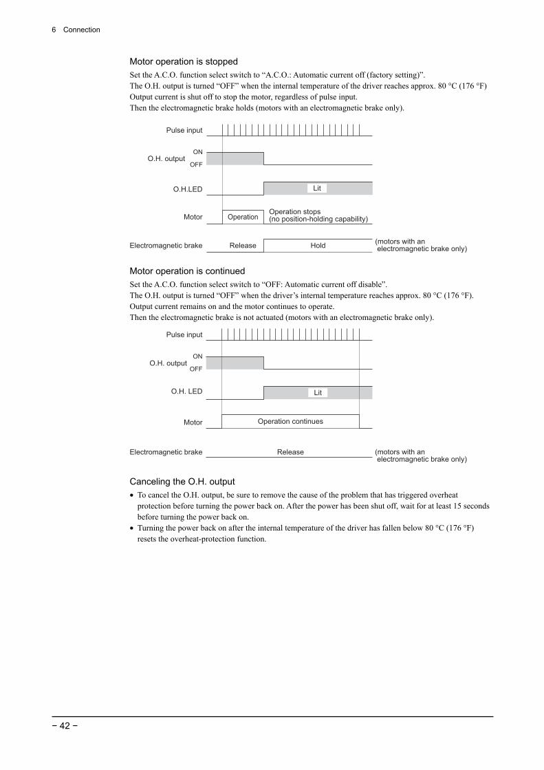
Motor operation is stopped Set the A.C.O. function select switch to “A.C.O.: Automatic current off (factory setting)”. The O.H. output is turned “OFF” when the internal temperature of the driver reaches approx. 80 °C (176 °F) Output current is shut off to stop the motor, regardless of pulse input. Then the electromagnetic brake holds (motors with an electromagnetic brake only).
Pulse input
O.H.LED
Motor OperationOperation stops(no position-holding capability)
O.H. outputON
OFF
Electromagnetic brake HoldRelease(motors with an electromagnetic brake only)
Lit
Motor operation is continued Set the A.C.O. function select switch to “OFF: Automatic current off disable”. The O.H. output is turned “OFF” when the driver’s internal temperature reaches approx. 80 °C (176 °F). Output current remains on and the motor continues to operate. Then the electromagnetic brake is not actuated (motors with an electromagnetic brake only).
Pulse input
O.H. LED
Motor
Lit
Operation continues
O.H. outputON
OFF
Electromagnetic brake Release (motors with an electromagnetic brake only)
Canceling the O.H. output • To cancel the O.H. output, be sure to remove the cause of the problem that has triggered overheat
protection before turning the power back on. After the power has been shut off, wait for at least 15 seconds before turning the power back on.
• Turning the power back on after the internal temperature of the driver has fallen below 80 °C (176 °F) resets the overheat-protection function.
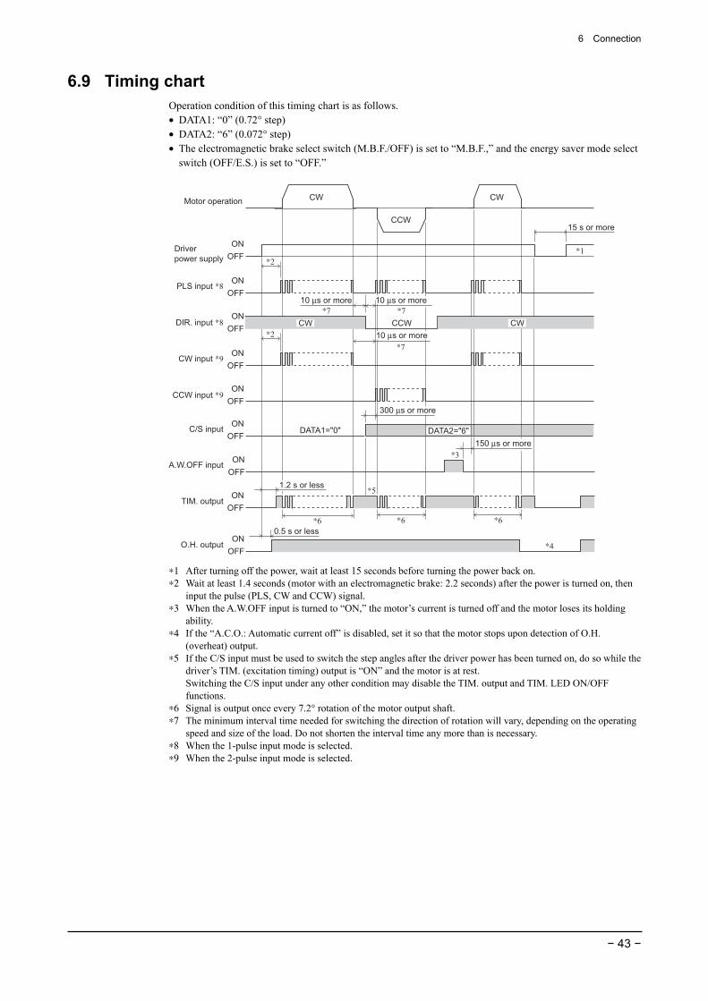
6 Connection
− 43 −
6.9 Timing chart Operation condition of this timing chart is as follows. • DATA1: “0” (0.72° step) • DATA2: “6” (0.072° step) • The electromagnetic brake select switch (M.B.F./OFF) is set to “M.B.F.,” and the energy saver mode select
switch (OFF/E.S.) is set to “OFF.”
Driver
power supply
C/S input
Motor operation
ON
OFF
ON
OFF
ON
OFF
ON
OFFA.W.OFF input
TIM. output
15 s or more
∗5
DATA1="0"
∗6 ∗6
∗3
CW
CCW
CW
∗1
O.H. outputON
OFF
0.5 s or less
∗6
∗4
150 µs or more
ON
OFF
ON
OFF
PLS input ∗8
DIR. input ∗8
∗2
CCW
10 µs or more
CW CW
ON
OFF
ON
OFF
CW input ∗9
CCW input ∗9
∗2
1.2 s or less
300 µs or more
10 µs or more∗7
10 µs or more
∗7
∗7
DATA2="6"
∗1 After turning off the power, wait at least 15 seconds before turning the power back on. ∗2 Wait at least 1.4 seconds (motor with an electromagnetic brake: 2.2 seconds) after the power is turned on, then
input the pulse (PLS, CW and CCW) signal. ∗3 When the A.W.OFF input is turned to “ON,” the motor’s current is turned off and the motor loses its holding
ability. ∗4 If the “A.C.O.: Automatic current off” is disabled, set it so that the motor stops upon detection of O.H.
(overheat) output. ∗5 If the C/S input must be used to switch the step angles after the driver power has been turned on, do so while the
driver’s TIM. (excitation timing) output is “ON” and the motor is at rest. Switching the C/S input under any other condition may disable the TIM. output and TIM. LED ON/OFF functions.
∗6 Signal is output once every 7.2° rotation of the motor output shaft. ∗7 The minimum interval time needed for switching the direction of rotation will vary, depending on the operating
speed and size of the load. Do not shorten the interval time any more than is necessary. ∗8 When the 1-pulse input mode is selected. ∗9 When the 2-pulse input mode is selected.
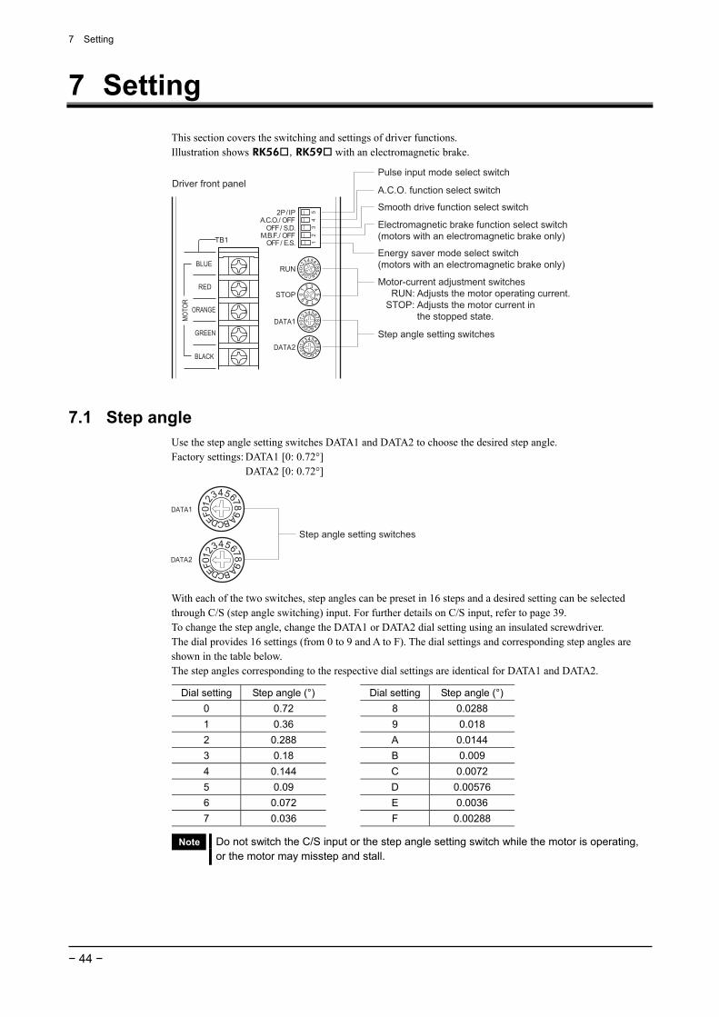
7 Setting
− 44 −
7 Setting This section covers the switching and settings of driver functions. Illustration shows RK56 , RK59 with an electromagnetic brake.
Pulse input mode select switch
A.C.O. function select switch
Smooth drive function select switch
Motor-current adjustment switches RUN: Adjusts the motor operating current. STOP: Adjusts the motor current in the stopped state.
Step angle setting switches
Driver front panel
Electromagnetic brake function select switch(motors with an electromagnetic brake only)
Energy saver mode select switch(motors with an electromagnetic brake only)
7.1 Step angle Use the step angle setting switches DATA1 and DATA2 to choose the desired step angle. Factory settings: DATA1 [0: 0.72°] DATA2 [0: 0.72°]
Step angle setting switches
With each of the two switches, step angles can be preset in 16 steps and a desired setting can be selected through C/S (step angle switching) input. For further details on C/S input, refer to page 39. To change the step angle, change the DATA1 or DATA2 dial setting using an insulated screwdriver. The dial provides 16 settings (from 0 to 9 and A to F). The dial settings and corresponding step angles are shown in the table below. The step angles corresponding to the respective dial settings are identical for DATA1 and DATA2.
Dial setting Step angle (°) Dial setting Step angle (°) 0 0.72 8 0.0288 1 0.36 9 0.018 2 0.288 A 0.0144 3 0.18 B 0.009 4 0.144 C 0.0072 5 0.09 D 0.00576 6 0.072 E 0.0036 7 0.036
F 0.00288
Note Do not switch the C/S input or the step angle setting switch while the motor is operating, or the motor may misstep and stall.
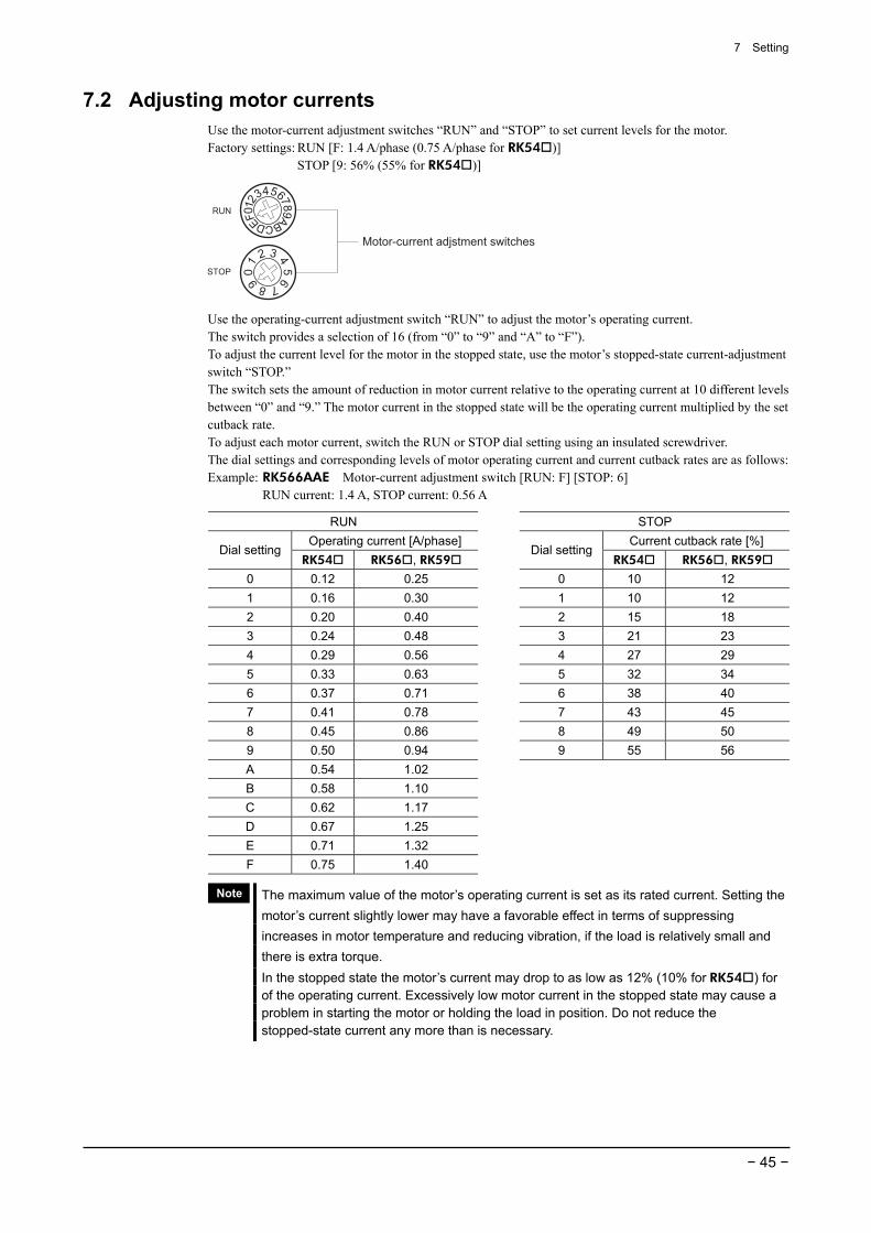
7 Setting
− 45 −
7.2 Adjusting motor currents Use the motor-current adjustment switches “RUN” and “STOP” to set current levels for the motor. Factory settings: RUN [F: 1.4 A/phase (0.75 A/phase for RK54 )] STOP [9: 56% (55% for RK54 )]
Motor-current adjstment switches
Use the operating-current adjustment switch “RUN” to adjust the motor’s operating current. The switch provides a selection of 16 (from “0” to “9” and “A” to “F”). To adjust the current level for the motor in the stopped state, use the motor’s stopped-state current-adjustment switch “STOP.” The switch sets the amount of reduction in motor current relative to the operating current at 10 different levels between “0” and “9.” The motor current in the stopped state will be the operating current multiplied by the set cutback rate. To adjust each motor current, switch the RUN or STOP dial setting using an insulated screwdriver. The dial settings and corresponding levels of motor operating current and current cutback rates are as follows: Example: RK566AAE Motor-current adjustment switch [RUN: F] [STOP: 6] RUN current: 1.4 A, STOP current: 0.56 A
RUN STOP Operating current [A/phase] Current cutback rate [%]
Dial setting RK54 RK56 , RK59
Dial settingRK54 RK56 , RK59
0 0.12 0.25 0 10 12 1 0.16 0.30 1 10 12 2 0.20 0.40 2 15 18 3 0.24 0.48 3 21 23 4 0.29 0.56 4 27 29 5 0.33 0.63 5 32 34 6 0.37 0.71 6 38 40 7 0.41 0.78 7 43 45 8 0.45 0.86 8 49 50 9 0.50 0.94 9 55 56 A 0.54 1.02 B 0.58 1.10 C 0.62 1.17 D 0.67 1.25 E 0.71 1.32 F 0.75 1.40
Note The maximum value of the motor’s operating current is set as its rated current. Setting the motor’s current slightly lower may have a favorable effect in terms of suppressing increases in motor temperature and reducing vibration, if the load is relatively small and there is extra torque. In the stopped state the motor’s current may drop to as low as 12% (10% for RK54 ) for of the operating current. Excessively low motor current in the stopped state may cause a problem in starting the motor or holding the load in position. Do not reduce the stopped-state current any more than is necessary.
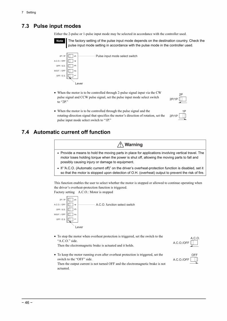
7 Setting
− 46 −
7.3 Pulse input modes Either the 2-pulse or 1-pulse input mode may be selected in accordance with the controller used.
Note The factory setting of the pulse input mode depends on the destination country. Check the pulse input mode setting in accordance with the pulse mode in the controller used.
Lever
Pulse input mode select switch
• When the motor is to be controlled through 2-pulse signal input via the CW pulse signal and CCW pulse signal, set the pulse input mode select switch to “2P.”
• When the motor is to be controlled through the pulse signal and the rotating-direction signal that specifies the motor’s direction of rotation, set the pulse input mode select switch to “1P.”
2P/1P
2P
2P/1P
1P
7.4 Automatic current off function
Warning
• Provide a means to hold the moving parts in place for applications involving vertical travel. The motor loses holding torque when the power is shut off, allowing the moving parts to fall and possibly causing injury or damage to equipment.
• If “A.C.O. (Automatic current off)” on the driver’s overheat-protection function is disabled, set it so that the motor is stopped upon detection of O.H. (overheat) output to prevent the risk of fire.
This function enables the user to select whether the motor is stopped or allowed to continue operating when the driver’s overheat-protection function is triggered. Factory setting A.C.O.: Motor is stopped
Lever
A.C.O. function select switch
• To stop the motor when overheat protection is triggered, set the switch to the “A.C.O.” side. Then the electromagnetic brake is actuated and it holds.
• To keep the motor running even after overheat protection is triggered, set the
switch to the “OFF” side. Then the output current is not turned OFF and the electromagnetic brake is not actuated.
A.C.O./OFF
A.C.O.
A.C.O./OFF
OFF
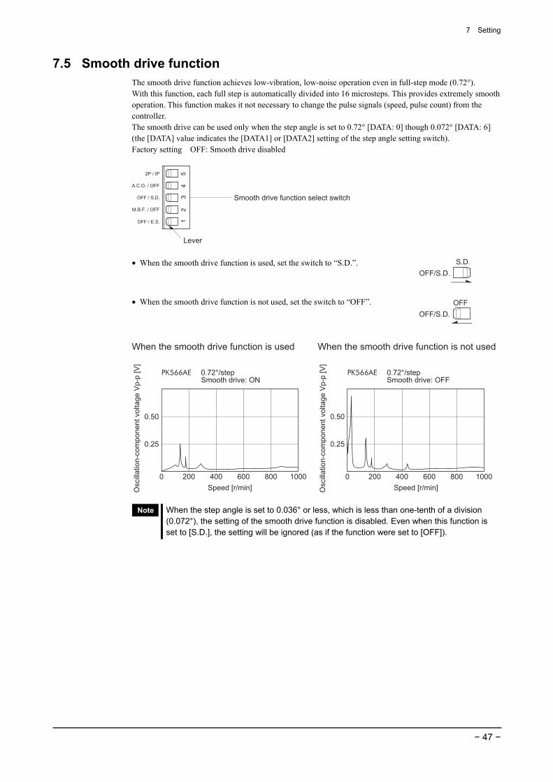
7 Setting
− 47 −
7.5 Smooth drive function The smooth drive function achieves low-vibration, low-noise operation even in full-step mode (0.72°). With this function, each full step is automatically divided into 16 microsteps. This provides extremely smooth operation. This function makes it not necessary to change the pulse signals (speed, pulse count) from the controller. The smooth drive can be used only when the step angle is set to 0.72° [DATA: 0] though 0.072° [DATA: 6] (the [DATA] value indicates the [DATA1] or [DATA2] setting of the step angle setting switch). Factory setting OFF: Smooth drive disabled
Lever
Smooth drive function select switch
• When the smooth drive function is used, set the switch to “S.D.”.
• When the smooth drive function is not used, set the switch to “OFF”.
OFF/S.D.
S.D.
OFF/S.D.
OFF
PK566AE 0.72°/step Smooth drive: ON
0 200 400 600 800 1000 0 200 400 600 800 1000
Speed [r/min]
When the smooth drive function is used When the smooth drive function is not used
Oscill
ation-c
om
ponent
voltage V
p-p
[V
]
0.50
0.25
Speed [r/min]Oscill
ation-c
om
ponent
voltage V
p-p
[V
]
0.50
0.25
PK566AE 0.72°/step Smooth drive: OFF
Note When the step angle is set to 0.036° or less, which is less than one-tenth of a division (0.072°), the setting of the smooth drive function is disabled. Even when this function is set to [S.D.], the setting will be ignored (as if the function were set to [OFF]).
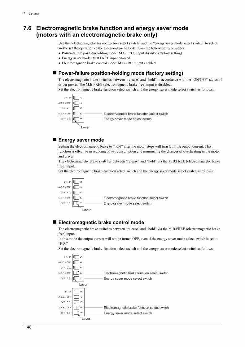
7 Setting
− 48 −
7.6 Electromagnetic brake function and energy saver mode (motors with an electromagnetic brake only)
Use the “electromagnetic brake-function select switch” and the “energy saver mode select switch” to select and/or set the operation of the electromagnetic brake from the following three modes: • Power-failure position-holding mode: M.B.FREE input disabled (factory setting) • Energy saver mode: M.B.FREE input enabled • Electromagnetic brake control mode: M.B.FREE input enabled
Power-failure position-holding mode (factory setting) The electromagnetic brake switches between “release” and “hold” in accordance with the “ON/OFF” status of driver power. The M.B.FREE (electromagnetic brake free) input is disabled. Set the electromagnetic brake-function select switch and the energy saver mode select switch as follows:
Lever
Electromagnetic brake function select switch
Energy saver mode select switch
Energy saver mode Setting the electromagnetic brake to “hold” after the motor stops will turn OFF the output current. This function is effective in reducing power consumption and minimizing the chances of overheating in the motor and driver. The electromagnetic brake switches between “release” and “hold” via the M.B.FREE (electromagnetic brake free) input. Set the electromagnetic brake-function select switch and the energy saver mode select switch as follows:
Lever
Electromagnetic brake function select switch
Energy saver mode select switch
Electromagnetic brake control mode The electromagnetic brake switches between “release” and “hold” via the M.B.FREE (electromagnetic brake free) input. In this mode the output current will not be turned OFF, even if the energy saver mode select switch is set to “E.S.” Set the electromagnetic brake-function select switch and the energy saver mode select switch as follows:
Electromagnetic brake function select switch
Energy saver mode select switch
Lever
Electromagnetic brake function select switch
Energy saver mode select switch
Lever
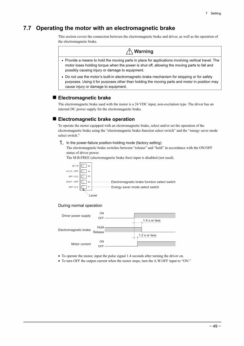
7 Setting
− 49 −
7.7 Operating the motor with an electromagnetic brake This section covers the connection between the electromagnetic brake and driver, as well as the operation of the electromagnetic brake.
Warning
• Provide a means to hold the moving parts in place for applications involving vertical travel. The motor loses holding torque when the power is shut off, allowing the moving parts to fall and possibly causing injury or damage to equipment.
• Do not use the motor’s built-in electromagnetic brake mechanism for stopping or for safety purposes. Using it for purposes other than holding the moving parts and motor in position may cause injury or damage to equipment.
Electromagnetic brake The electromagnetic brake used with the motor is a 24 VDC input, non-excitation type. The driver has an internal DC power supply for the electromagnetic brake.
Electromagnetic brake operation To operate the motor equipped with an electromagnetic brake, select and/or set the operation of the electromagnetic brake using the “electromagnetic brake-function select switch” and the “energy saver mode select switch.”
1. In the power-failure position-holding mode (factory setting) The electromagnetic brake switches between “release” and “hold” in accordance with the ON/OFF status of driver power. The M.B.FREE (electromagnetic brake free) input is disabled (not used).
Lever
Electromagnetic brake function select switch
Energy saver mode select switch
During normal operation
Driver power supply
Electromagnetic brake
ON
OFF
Hold
Release
ON
OFFMotor current
1.4 s or less
1.2 s or less
• To operate the motor, input the pulse signal 1.4 seconds after turning the driver on. • To turn OFF the output current when the motor stops, turn the A.W.OFF input to “ON.”
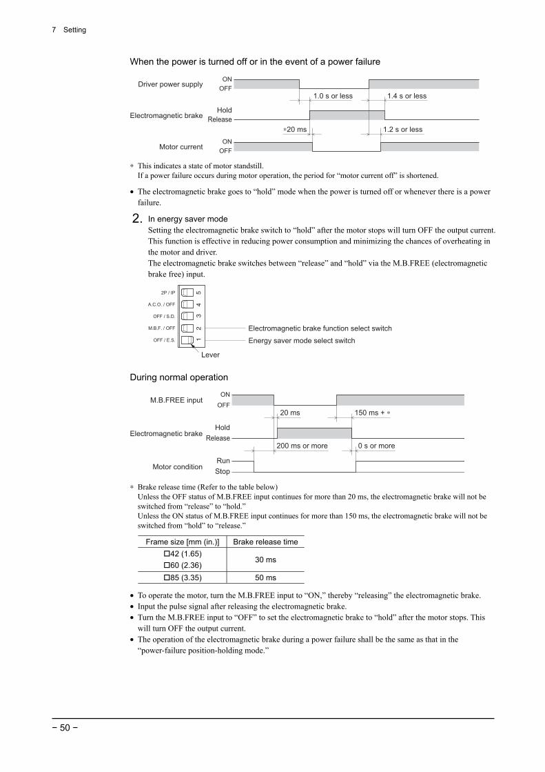
7 Setting
− 50 −
When the power is turned off or in the event of a power failure
Driver power supplyON
OFF
Hold
Release
ON
OFF
1.0 s or less
Electromagnetic brake
Motor current
∗20 ms
1.4 s or less
1.2 s or less
∗ This indicates a state of motor standstill. If a power failure occurs during motor operation, the period for “motor current off” is shortened.
• The electromagnetic brake goes to “hold” mode when the power is turned off or whenever there is a power failure.
2. In energy saver mode Setting the electromagnetic brake switch to “hold” after the motor stops will turn OFF the output current. This function is effective in reducing power consumption and minimizing the chances of overheating in the motor and driver. The electromagnetic brake switches between “release” and “hold” via the M.B.FREE (electromagnetic brake free) input.
Lever
Electromagnetic brake function select switch
Energy saver mode select switch
During normal operation
M.B.FREE input
Electromagnetic brakeHold
Release
ON
OFF
Run
StopMotor condition
20 ms 150 ms + ∗
0 s or more200 ms or more
∗ Brake release time (Refer to the table below) Unless the OFF status of M.B.FREE input continues for more than 20 ms, the electromagnetic brake will not be switched from “release” to “hold.” Unless the ON status of M.B.FREE input continues for more than 150 ms, the electromagnetic brake will not be switched from “hold” to “release.”
Frame size [mm (in.)] Brake release time42 (1.65) 60 (2.36)
30 ms
85 (3.35) 50 ms
• To operate the motor, turn the M.B.FREE input to “ON,” thereby “releasing” the electromagnetic brake. • Input the pulse signal after releasing the electromagnetic brake. • Turn the M.B.FREE input to “OFF” to set the electromagnetic brake to “hold” after the motor stops. This
will turn OFF the output current. • The operation of the electromagnetic brake during a power failure shall be the same as that in the
“power-failure position-holding mode.”
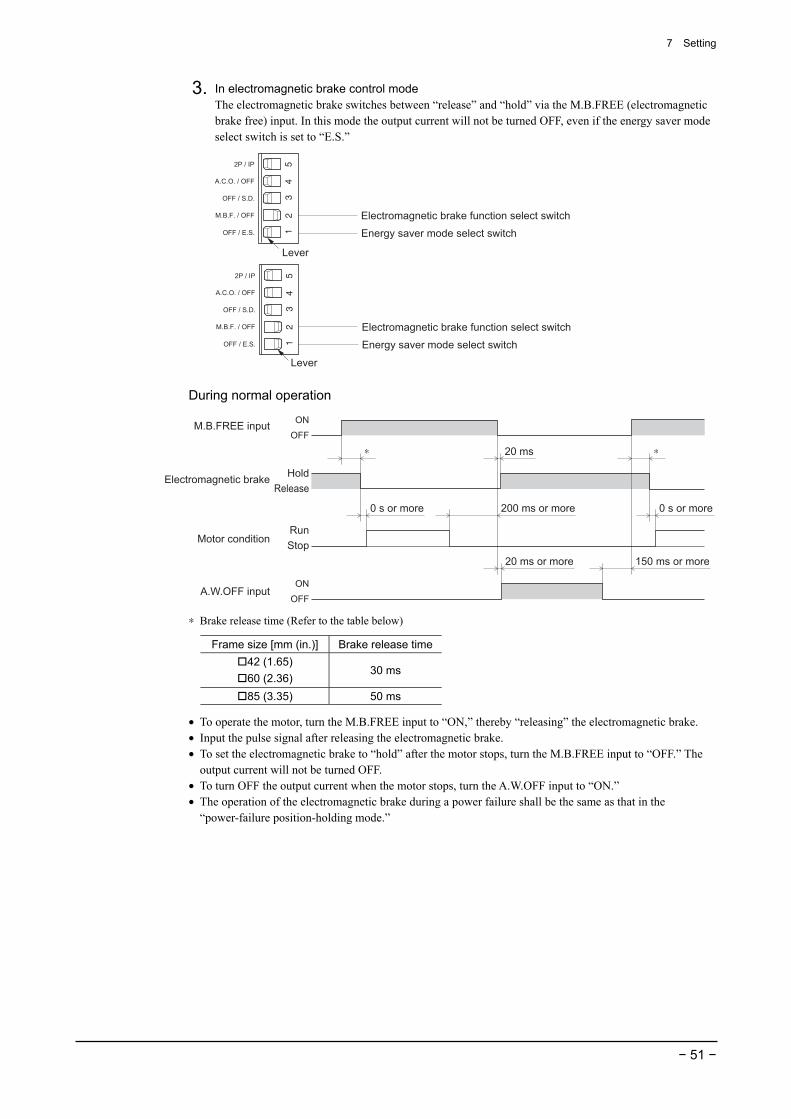
7 Setting
− 51 −
3. In electromagnetic brake control mode The electromagnetic brake switches between “release” and “hold” via the M.B.FREE (electromagnetic brake free) input. In this mode the output current will not be turned OFF, even if the energy saver mode select switch is set to “E.S.”
Electromagnetic brake function select switch
Energy saver mode select switch
Lever
Electromagnetic brake function select switch
Energy saver mode select switch
Lever
During normal operation
M.B.FREE input
Electromagnetic brakeHold
ON
RunMotor condition
A.W.OFF input
20 ms
150 ms or more
0 s or more
∗
0 s or more 200 ms or more
20 ms or more
∗OFF
ON
OFF
Stop
Release
∗ Brake release time (Refer to the table below)
Frame size [mm (in.)] Brake release time42 (1.65) 60 (2.36)
30 ms
85 (3.35) 50 ms
• To operate the motor, turn the M.B.FREE input to “ON,” thereby “releasing” the electromagnetic brake. • Input the pulse signal after releasing the electromagnetic brake. • To set the electromagnetic brake to “hold” after the motor stops, turn the M.B.FREE input to “OFF.” The
output current will not be turned OFF. • To turn OFF the output current when the motor stops, turn the A.W.OFF input to “ON.” • The operation of the electromagnetic brake during a power failure shall be the same as that in the
“power-failure position-holding mode.”
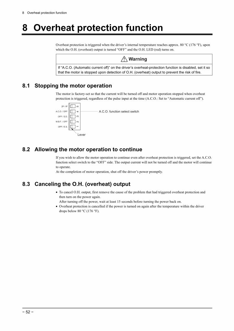
8 Overheat protection function
− 52 −
8 Overheat protection function Overheat protection is triggered when the driver’s internal temperature reaches approx. 80 °C (176 °F), upon which the O.H. (overheat) output is turned “OFF” and the O.H. LED (red) turns on.
Warning
If “A.C.O. (Automatic current off)” on the driver’s overheat-protection function is disabled, set it so that the motor is stopped upon detection of O.H. (overheat) output to prevent the risk of fire.
8.1 Stopping the motor operation The motor is factory-set so that the current will be turned off and motor operation stopped when overheat protection is triggered, regardless of the pulse input at the time (A.C.O.: Set to “Automatic current off”).
Lever
A.C.O. function select switch
8.2 Allowing the motor operation to continue If you wish to allow the motor operation to continue even after overheat protection is triggered, set the A.C.O. function select switch to the “OFF” side. The output current will not be turned off and the motor will continue to operate. At the completion of motor operation, shut off the driver’s power promptly.
8.3 Canceling the O.H. (overheat) output • To cancel O.H. output, first remove the cause of the problem that had triggered overheat protection and
then turn on the power again. After turning off the power, wait at least 15 seconds before turning the power back on.
• Overheat protection is cancelled if the power is turned on again after the temperature within the driver drops below 80 °C (176 °F).
9 Inspection
− 53 −
9 Inspection It is recommended that periodic inspections be conducted for the items listed below after each operation of the motor. If an abnormal condition is noted, discontinue any use and contact your nearest office.
• Are any of the motor mounting screws loose? • Are there any abnormal sounds from the motor’s bearing section (ball bearings) or elsewhere? • Is there any deviation between the centers of the motor’s output shaft and load shaft? • Do any of the motor cables have damage or stress, or is there any play at the section for connection with
the driver? • Check for a blocked opening of the driver case. • Are any of the driver mounting screws or power-connection terminal screws loose? • Are there any strange smells or appearances in the driver?
Note The driver uses power device and semiconductor elements, so be extremely careful when handling them. Static electricity may damage the driver.
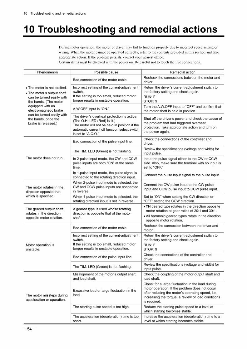
10 Troubleshooting and remedial actions
− 54 −
10 Troubleshooting and remedial actions During motor operation, the motor or driver may fail to function properly due to incorrect speed setting or wiring. When the motor cannot be operated correctly, refer to the contents provided in this section and take appropriate action. If the problem persists, contact your nearest office. Certain items must be checked with the power on. Be careful not to touch the live connections.
Phenomenon Possible cause Remedial action
Bad connection of the motor cable. Recheck the connections between the motor and driver.
Incorrect setting of the current-adjustment switch. If the setting is too small, reduced motor torque results in unstable operation.
Return the driver’s current-adjustment switch to the factory setting and check again. RUN: F STOP: 9
A.W.OFF input is “ON.” Turn the A.W.OFF input to “OFF” and confirm that the motor shaft is held in position.
• The motor is not excited. • The motor’s output shaft
can be turned easily with the hands. (The motor equipped with an electromagnetic brake can be turned easily with the hands, once the brake is released.)
The driver’s overheat protection is active. (The O.H. LED (Red) is lit.) The motor will not be held in position if the automatic current off function select switch is set to “A.C.O.”
Shut off the driver’s power and check the cause of the problem that had triggered overheat protection. Take appropriate action and turn on the power again.
Bad connection of the pulse input line. Check the connections of the controller and driver.
The TIM. LED (Green) is not flashing. Review the specifications (voltage and width) for input pulse.
In 2-pulse input mode, the CW and CCW pulse inputs are both “ON” at the same time.
Input the pulse signal either to the CW or CCW side. Also, make sure the terminal with no input is set to “OFF.”
The motor does not run.
In 1-pulse input mode, the pulse signal is connected to the rotating direction input. Connect the pulse input signal to the pulse input.
When 2-pulse input mode is selected, the CW and CCW pulse inputs are connected in reverse.
Connect the CW pulse input to the CW pulse input and CCW pulse input to CCW pulse input. The motor rotates in the
direction opposite that which is specified. When 1-pulse input mode is selected, the
rotating direction input is set in reverse. Set to “ON” when setting the CW direction or “OFF” setting the CCW direction.
The geared output shaft rotates in the direction opposite motor rotation.
A geared type is used whose rotating direction is opposite that of the motor shaft.
• TH geared type rotates in the direction opposite motor rotation at gear ratios of 20:1 and 30:1.
• All harmonic geared types rotate in the direction opposite motor rotation.
Bad connection of the motor cable. Recheck the connection between the driver and motor.
Incorrect setting of the current-adjustment switch. If the setting is too small, reduced motor torque results in unstable operation.
Return the driver’s current-adjustment switch to the factory setting and check again. RUN: F STOP: 9
Bad connection of the pulse input line. Check the connections of the controller and driver.
Motor operation is unstable.
The TIM. LED (Green) is not flashing. Review the specifications (voltage and width) for input pulse.
Misalignment of the motor’s output shaft and load shaft.
Check the coupling of the motor output shaft and load shaft.
Excessive load or large fluctuation in the load.
Check for a large fluctuation in the load during motor operation. If the problem does not occur after reducing the motor’s operating speed, i.e., increasing the torque, a review of load conditions is required.
The starting pulse speed is too high. Reduce the starting pulse speed to a level at which starting becomes stable.
The motor missteps during acceleration or operation.
The acceleration (deceleration) time is too short.
Increase the acceleration (deceleration) time to a level at which starting becomes stable.
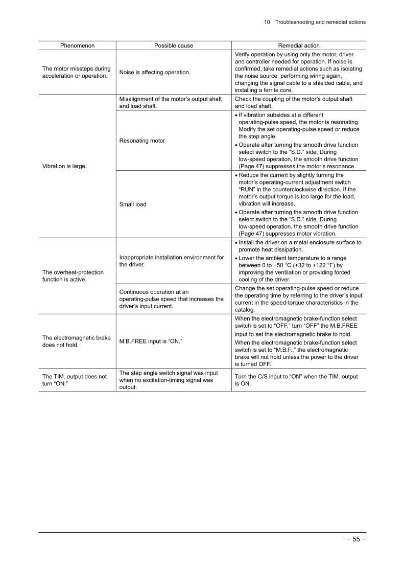
10 Troubleshooting and remedial actions
− 55 −
Phenomenon Possible cause Remedial action
The motor missteps during acceleration or operation. Noise is affecting operation.
Verify operation by using only the motor, driver and controller needed for operation. If noise is confirmed, take remedial actions such as isolating the noise source, performing wiring again, changing the signal cable to a shielded cable, and installing a ferrite core.
Misalignment of the motor’s output shaft and load shaft.
Check the coupling of the motor’s output shaft and load shaft.
Resonating motor
• If vibration subsides at a different operating-pulse speed, the motor is resonating. Modify the set operating-pulse speed or reduce the step angle.
• Operate after turning the smooth drive function select switch to the “S.D.” side. During low-speed operation, the smooth drive function (Page 47) suppresses the motor’s resonance. Vibration is large.
Small load
• Reduce the current by slightly turning the motor’s operating-current adjustment switch “RUN” in the counterclockwise direction. If the motor’s output torque is too large for the load, vibration will increase.
• Operate after turning the smooth drive function select switch to the “S.D.” side. During low-speed operation, the smooth drive function (Page 47) suppresses motor vibration.
Inappropriate installation environment for the driver.
• Install the driver on a metal enclosure surface to promote heat dissipation.
• Lower the ambient temperature to a range between 0 to +50 °C (+32 to +122 °F) by improving the ventilation or providing forced cooling of the driver.
The overheat-protection function is active.
Continuous operation at an operating-pulse speed that increases the driver’s input current.
Change the set operating-pulse speed or reduce the operating time by referring to the driver’s input current in the speed-torque characteristics in the catalog.
The electromagnetic brake does not hold. M.B.FREE input is “ON.”
When the electromagnetic brake-function select switch is set to “OFF,” turn “OFF” the M.B.FREE input to set the electromagnetic brake to hold. When the electromagnetic brake-function select switch is set to “M.B.F.,” the electromagnetic brake will not hold unless the power to the driver is turned OFF.
The TIM. output does not turn “ON.”
The step angle switch signal was input when no excitation-timing signal was output.
Turn the C/S input to “ON” when the TIM. output is ON.

11 Specifications
− 56 −
11 Specifications This section covers the main specifications of the RK series 5-phase stepping motors. Refer to the catalog for detailed specifications, torque characteristics and dimensions.
Motor (Excluding standard type terminal box)
Standard type terminal box Driver
Degree of protection IP30 IP65∗ IP00
Ambient temperature
−10 to +50 °C (+14 to +122 °F) (non-freezing) Harmonic geared type: 0 to +40 °C (+32 to +104 °F) (non-freezing)
0 to +50 °C (+32 to +122 °F) (non-freezing)
Humidity 85% or less (non-condensing) Altitude Up to 1000 m (3300 ft.) above sea level
Operation environment
Surrounding atmosphere
No corrosive gas, dust, water or oil No corrosive gas No corrosive gas,
dust, water or oil
Ambient temperature −20 to +60 °C (−4 to +140 °F) (non-freezing)
−25 to +70 °C (−13 to +158 °F) (non-freezing)
Humidity 85% or less (non-condensing) Altitude Up to 3000 m (10 000 ft.) above sea level
Storage environment
Surrounding atmosphere
No corrosive gas, dust, water or oil No corrosive gas No corrosive gas,
dust, water or oil
Ambient temperature −20 to +60 °C (−4 to +140 °F) (non-freezing)
−25 to +70 °C (−13 to +158 °F) (non-freezing)
Humidity 85% or less (non-condensing) Altitude Up to 3000 m (10 000 ft.) above sea level
Shipping environment
Surrounding atmosphere
No corrosive gas, dust, water or oil No corrosive gas No corrosive gas,
dust, water or oil ∗ Excluding the gap between the shaft and the flange
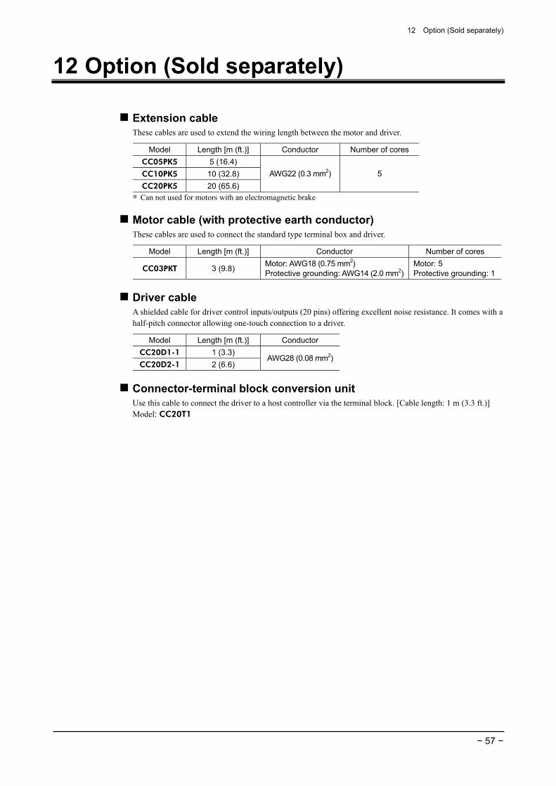
12 Option (Sold separately)
− 57 −
12 Option (Sold separately)
Extension cable These cables are used to extend the wiring length between the motor and driver.
Model Length [m (ft.)] Conductor Number of cores CC05PK5 5 (16.4) CC10PK5 10 (32.8) CC20PK5 20 (65.6)
AWG22 (0.3 mm2) 5
∗ Can not used for motors with an electromagnetic brake
Motor cable (with protective earth conductor) These cables are used to connect the standard type terminal box and driver.
Model Length [m (ft.)] Conductor Number of cores
CC03PKT 3 (9.8) Motor: AWG18 (0.75 mm2) Protective grounding: AWG14 (2.0 mm2)
Motor: 5 Protective grounding: 1
Driver cable A shielded cable for driver control inputs/outputs (20 pins) offering excellent noise resistance. It comes with a half-pitch connector allowing one-touch connection to a driver.
Model Length [m (ft.)] Conductor CC20D1-1 1 (3.3) CC20D2-1 2 (6.6)
AWG28 (0.08 mm2)
Connector-terminal block conversion unit Use this cable to connect the driver to a host controller via the terminal block. [Cable length: 1 m (3.3 ft.)] Model: CC20T1


• Unauthorized reproduction or copying of all or part of this manual is prohibited. If a new copy is required to replace an original manual that has been damaged or lost, please contact your nearest Oriental Motor branch or sales office.
• Oriental Motor shall not be liable whatsoever for any problems relating to industrial property rights arising from use of any information, circuit, equipment or device provided or referenced in this manual.
• Characteristics, specifications and dimensions are subject to change without notice. • While we make every effort to offer accurate information in the manual, we welcome your input. Should you find unclear
descriptions, errors or omissions, please contact the nearest office. • is a registered trademark or trademark of Oriental Motor Co., Ltd., in Japan and other countries.
Other product names and company names mentioned in this manual may be registered trademarks or trademarks of their respective companies and are hereby acknowledged. The third-party products mentioned in this manual are recommended products, and references to their names shall not be construed as any form of performance guarantee. Oriental Motor is not liable whatsoever for the performance of these third-party products.
© Copyright ORIENTAL MOTOR CO., LTD. 2010
Printed on Recycled Paper
• Please contact your nearest Oriental Motor office for further information.
Technical Support Tel:(800)468-39828:30 A.M. to 5:00 P.M., P.S.T. (M-F)7:30 A.M. to 5:00 P.M., C.S.T. (M-F)E-mail: [email protected]
Headquarters and Düsseldorf OfficeTel:0211-52067-00 Fax:0211-52067-099Munich Office Tel:089-3181225-00 Fax:089-3181225-25Hamburg OfficeTel:040-76910443 Fax:040-76910445
Tel:01256-347090 Fax:01256-347099
Tel:01 47 86 97 50 Fax:01 47 82 45 16
Tel:02-93906346 Fax:02-93906348
Tel:(02)8228-0707 Fax:(02)8228-0708
Tel:(6745)7344 Fax:(6745)9405
Tel:(03)22875778 Fax:(03)22875528
KOREATel:(032)822-2042~3 Fax:(032)819-8745
Headquarters Tokyo, JapanTel:(03)3835-0684 Fax:(03)3835-1890
Tel:66-2-254-6113 Fax:66-2-254-6114