Embed Size (px)
Citation preview
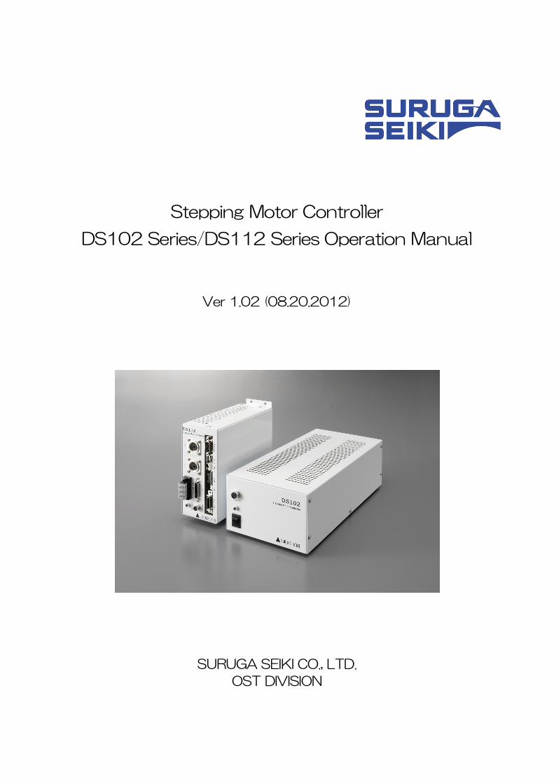
Stepping Motor Controller
DS102 Series/DS112 Series Operation Manual
Ver 1.02 (08.20.2012)
SURUGA SEIKI CO., LTD.
OST DIVISION
Index
1.INTRODUCTION...................................................................................................................................................... 5
1.1 FOR YOUR SAFETY ................................................................................................................................................... 5
1.2 PRODUCT OUTLINE / FEATURES ............................................................................................................................. 7
1.3 S STEM CONFIGURATION EXAMPLEY ........................................................................................................................ 9
1.3.1 CONTROL WITH PLC........................................................................................................................................ 9
1.3.2 CONTROLLED BY PC .....................................................................................................................................10
1.4 ACCESSORIES.........................................................................................................................................................11
2.SET-UP AND EXAMPLE OF USE ............................................................................................................11
2.1 SET UP BEFORE USE..............................................................................................................................................11
2.1.1 CONNECTING...................................................................................................................................................12
2.1.2 USB DRIVER INSTALL ..................................................................................................................................15
2.1.3 INSTALLATION FOR CONTROL SOFTWARE DS102/112(DSCONTROL-WIN)...............................19
2.1.4 A JUSTMENT SYSTEM PARAMETERD ............................................................................................................23
2.1.5 OPERATION CHECK........................................................................................................................................25
2.2 SYSTEM ARCHITECTURE.......................................................................................................................................27
2.2.1 M VEMENT BETWEEN EACH TEACHING POSITIONO .....................................................................................27
2.2.2 E SY RETURN TO ORIGIN POSITIONA ...............................................................................................................34
2.2.3 C NTROL BY EXTERNAL SIGNALO ..................................................................................................................43
2.2.4 E TERNAL DEVICE CONTROL WITH GENERALI/O.X ...................................................................................54
2.2.5 M VE TO ARBITRARY COORDINATEO .............................................................................................................56
2.2.6 CONTROLLED OVER 3 AXES.........................................................................................................................58
3.SPEC AND FUNCTION...................................................................................................................................59
3.1 BASIC SPEC..........................................................................................................................................................59
3.2 P RT NAME AND FUNCTIONSA ...............................................................................................................................60
3.3 SETTING....................................................................................................................................................................63
3.4 EXTERNAL INTERFACE ............................................................................................................................................64
3.4.1 LINK CONNECTION(LINK)............................................................................................................................64
3.4.2 CONTROL INPUT/OUTPUT(CNT-I/O).....................................................................................................65
3.4.3 GENERAL I/O(I/O)(OPTION)...................................................................................................................68
3.4.4 EMERGENCY STOP INPUT(EMS)...............................................................................................................70
3.4.5 STAGE INTERFACE............................................................................................................................................70
3.5 DRIVER DIVISION NUMBER SETTING........................................................................................................................71
3.5.1 O EN AND SHUTP ...............................................................................................................................................71
3.5.2 S TTING DIVISION NUMBERE ..............................................................................................................................71
3.6 S OOTH DRIVE FUNCTION(ONLY MS TYPE)M ...................................................................................................72
3.7 UNITS SETTING FUNCTION ......................................................................................................................................73
3.8 S EED SETTING(SPEED TABLE)P ........................................................................................................................74
3.9 FUNCTION OF ORIGIN RETURN ................................................................................................................................77
3.10 LINEAR INTERPOLATING FUNCTION.....................................................................................................................83
3.10.1 LINEAR INTERPOLATING(RELATIVE VALUE)..........................................................................................83
3.10.2 LINEAR INTERPOLATING(ABSOLUTE VALUE)........................................................................................83
3.11 TEACHING FUNCTION............................................................................................................................................84
3.12 PROGRAM FUNCTION............................................................................................................................................84
2
3
4.OPERATION AND CONTROL METHOD.................................................................................................85
4.1 O ERATION BY THE HANDY TERMINALP .................................................................................................................85
4.1.1 INITIAL SCREEN..................................................................................................................................................85
4.1.2 T ANSITION MODER ............................................................................................................................................86
4.1.3 DRIVING MODE SELECT(JOG KEY).........................................................................................................87
4.1.3.1 C NTINUOUS DRIVING MODE(CNT:CONTINUE MODE)O ................................................................87
4.1.3.2 U IFORM PULSE DRIVING MODE(STP: STEP MODE)N ...................................................................87
4.1.3.3 ABSOLUTE VALUE DRIVING MODE(ABS: ABSOLUTE MODE).....................................................88
4.1.3.4 ORIGIN RETURN MODE(ORG: ORIGIN MODE)................................................................................88
4.1.3.5 HOME POSITION RETURN MODE(HOM:HOME)............................................................................88
4.1.4 MENU SELECT(MENU KEY)........................................................................................................................89
4.1.4.1 PARAMETER MODE(PRM)..................................................................................................................89
4.1.4.2 PROGRAM DRIVING MODE(PRG)......................................................................................................98
4.1.4.3 TEACHING MODE (TCH)....................................................................................................................99
4.1.4.4 GENERAL MONITOR(IN)...................................................................................................................102
4.1.4.5 G NERAL OUTPUT CONTROL(OUT)E ..............................................................................................102
4.1.5 OTHER FUNCTION..........................................................................................................................................103
4.1.5.1 CHANGE THE SPEED TABLE(SPD KEY).......................................................................................103
4.1.5.2 CHANGE THE AXIS(LINK KEY).........................................................................................................103
4.1.5.3 C ANGES CURRENT POSITION(POS KEY)H ....................................................................................103
4.1.5.4 V RSION CONFIRMATION, PARAMETER RESETE ...................................................................................104
4.2 DS102/112 CONTROLLED SOFTWARE(DSCONTROL-WIN)...........................................................105
4.2.1 DSCONTROL-WIN START-UP...............................................................................................................105
4.2.2 PARAMETER SET-UP.....................................................................................................................................105
4.2.3 JOG DRIVING...................................................................................................................................................107
4.2.4 TEACHING.......................................................................................................................................................110
4.2.5 DRIVING PROGRAM........................................................................................................................................112
4.2.6 I/O MONITOR............................................................................................................................................118
4.3 USER PROGRAM P OCESSINGR .............................................................................................................................119
4.3.1 RS232C......................................................................................................................................................119
4.3.2 USB ..............................................................................................................................................................120
4.3.3 D LIMITERE .......................................................................................................................................................122
4.3.4 T PES OF COMMUNICATION COMMANDY ......................................................................................................123
4.3.5 DETAILS OF C MMUNICATION C MMANDO O .................................................................................................135
4.3.5.1 AXIS SPECIFICATION COMMAND...........................................................................................................135
4.3.5.2 PARAMETER SETTING COMMAND ........................................................................................................135
4.3.5.3 M MORY SW SETTING C MMANDE O .....................................................................................................139
4.3.5.4 SPEED TABLE SETTING C MMANDO ....................................................................................................140
4.3.5.5 WRITE C MMANDO ..................................................................................................................................141
4.3.5.6 DRIVING C MMANDO ...............................................................................................................................141
4.3.5.7 STOP C MMANDO ...................................................................................................................................142
4.3.5.8 PARAMETER SETTING REQUEST C MMANDO .....................................................................................143
4.3.5.9 M MORY SW SETTING REQUEST C MMANDE O ...................................................................................145
4.3.5.10 SPEED TABLE SETTING REQUEST C MMANDO ...............................................................................147
4.3.5.11 STATUS REQUEST C MMANDO ..........................................................................................................147
4.3.5.12 GENERAL I/O C MMANDO ..................................................................................................................152
4.3.6 PROGRAM DRIVING DEDICATED C MMANDO ..............................................................................................153
4.3.7 ERROR CODE .................................................................................................................................................156
4
5.CHECKOUT..........................................................................................................................................................157
6.FAULT DIAGNOSIS AND SOLUTION....................................................................................................157
7.WARRANTY & CUSTOMER SERVICE..................................................................................................158
● APPENDIX..................................................................................................................................................................159
■ DIP SWITCH SET........................................................................................................................................................................159
■ DS102 EXTERNALS................................................................................................................................................................160
■ DS112 EXTERNALS................................................................................................................................................................161
■ CONTROL I/O CABLE(MODEL:DS100-CNT-2)..................................................................................................162
■ GENERAL I/O CABLE(MODEL:DS100-IO-2)......................................................................................................163
■ SELECTION OF A PROGRAM NUMBER BY CNT-IO...........................................................................................................164
■ S LECTION OF A TEACHING NUMBER BY CNT-IOE ...........................................................................................................164
<CONTACT INFORMATION>...........................................................................................................................166
1.INTRODUCTION
Thank you for purchasing this series Stepping Motor Controller.
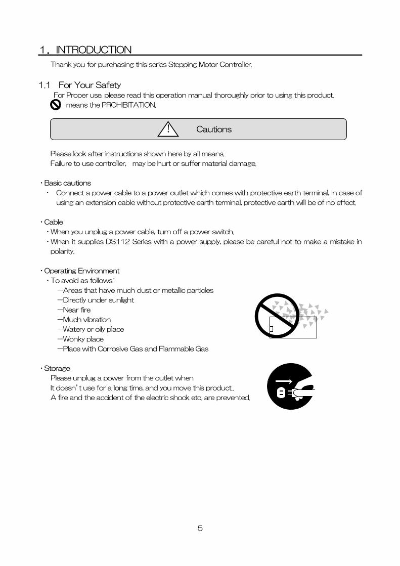
1.1 For Your Safety For Proper use, please read this operation manual thoroughly prior to using this product.
means the PROHIBITATION.
Cautions !
Please look after instructions shown here by all means.
Failure to use controller, may be hurt or suffer material damage.
・Basic cautions
・ Connect a power cable to a power outlet which comes with protective earth terminal, In case of
using an extension cable without protective earth terminal, protective earth will be of no effect.
・Cable
・When you unplug a power cable, turn off a power switch.
・When it supplies DS112 Series with a power supply, please be careful not to make a mistake in
polarity.
・Operating Environment
・To avoid as follows.:
-Areas that have much dust or metallic particles
-Directly under sunlight
-Near fire
-Much vibration
-Watery or oily place
-Wonky place
-Place with Corrosive Gas and Flammable Gas
・Storage
Please unplug a power from the outlet when
It doesn’t use for a long time, and you move this product..
A fire and the accident of the electric shock etc. are prevented.
5
Caution !
・Power Source
・Please DO NOT connect the DS102 series besides the power supply outlet of interchange 100~
240V (AC100~240V 50/60Hz)
・Please supply direct 24V(DC24V±10%)power supply for DS112 series.
In order to avoid damage to controller, DO NOT use any input voltage or frequency over
the specifications.
・Resolution of the product/Remodeling
6
・ Please DO NOT perform the resolution of the product, remodeling, the
unfair repair.
・ Please contact us for correct information if needed.
・Repair Service
・ In the case of the following, please disconnect the plug promptly and then
contact our OST DIVISION SALES GROUP
-When there are some strange sound, smelling and smoke.
-When a power supply cable damaged.
-When spilled water on the equipment and foreign materials entered
inside.
-When dropped the equipment and was damaged with a cabinet.
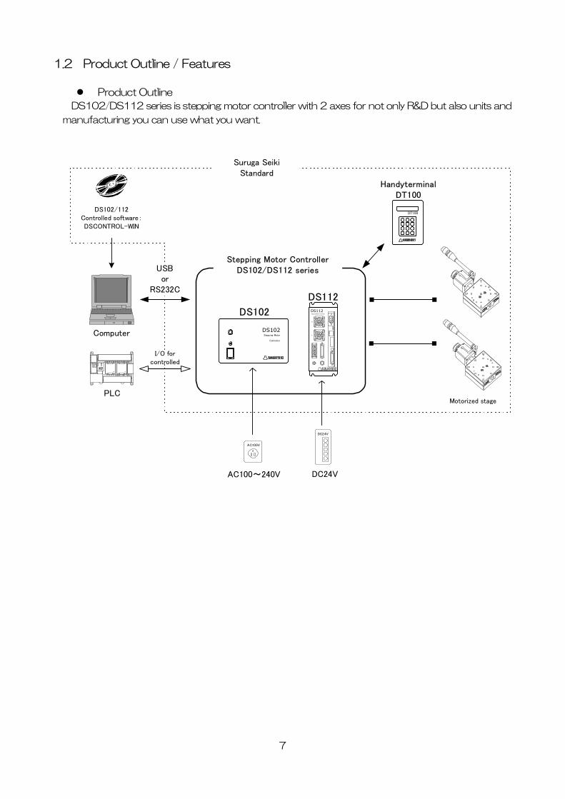
1.2 Product Outline / Features
Product Outline
DS102/DS112 series is stepping motor controller with 2 axes for not only R&D but also units and
manufacturing you can use what you want.
Computer
PLC
DC24V
AC100V
XY
DS112Stepping Motor Controller
DS112
Stepping Motor ControllerDS102/DS112 series
AC100~240V DC24V
Motorized stage
DS102/112Controlled software:DSCONTROL-WIN
DS102Stepping Motor
Controller
DS102
Suruga SeikiStandard
DT100
HandyterminalDT100
I/O forcontrolled
USBor
RS232C
7
8
Features
1. Controlled
・ 5 phase stepping motor is controlled by 2 axes
・ Linear interpolation of 2 axes
・ 2 types motor driver with normal(FULL/HALF) and micro-step(16 levels)
As a microstep type, it is possible to highly positioning control and low vibration with
Smooth drive function.
・ It is possible to control 6 axes with link function.
Up to 24 axes can be controlled with USB Hub.
2. Drive
・ Teaching point movement
・ Program Drive
・ Jog Drive
・ It is possible to memorize teaching point 64 points and 8 of programs.
3. Interface
・ Connected USB、RS232C
・ DS102/112 controlled software:DSCONTROL-WIN
・ Handy terminal:DT100
・ I/O for controlled
・ General I/O:Input16points、output12points (Option)
・ 2 types of PS/V AC100~240V、DC24V
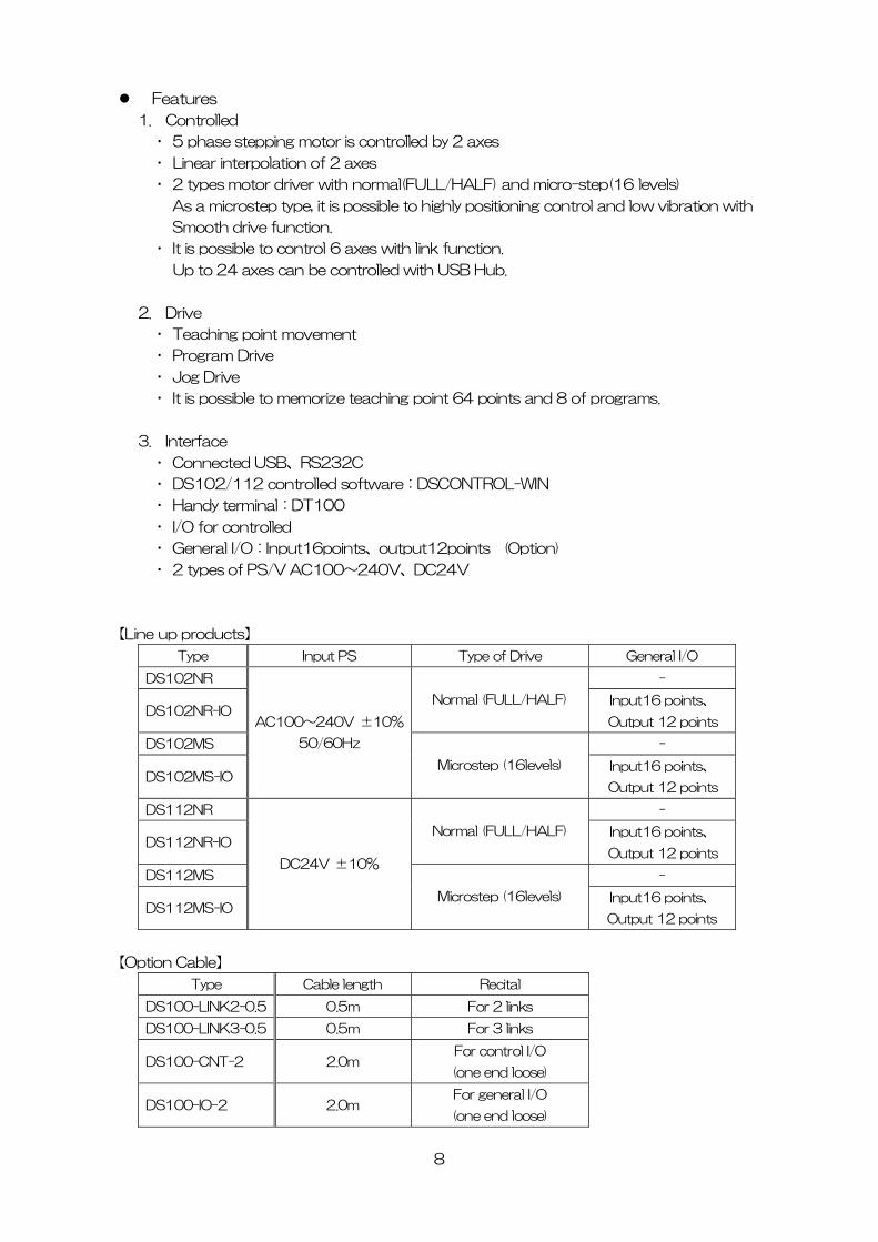
【Line up products】
Type Input PS Type of Drive General I/O
DS102NR -
DS102NR-IO Normal (FULL/HALF) Input16 points、
Output 12 points
DS102MS -
DS102MS-IO
AC100~240V ±10%
50/60Hz
Microstep (16levels) Input16 points、
Output 12 points
DS112NR -
DS112NR-IO Normal (FULL/HALF) Input16 points、
Output 12 points
DS112MS -
DS112MS-IO
DC24V ±10%
Microstep (16levels) Input16 points、
Output 12 points
【Option Cable】
Type Cable length Recital
DS100-LINK2-0.5 0.5m For 2 links
DS100-LINK3-0.5 0.5m For 3 links
DS100-CNT-2 2.0m For control I/O
(one end loose)
DS100-IO-2 2.0m For general I/O
(one end loose)
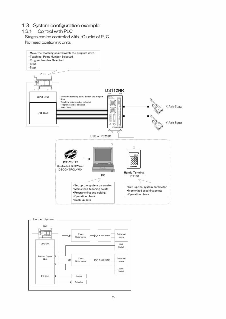
1.3 System configuration example
1.3.1 Control with PLC
Stages can be controlled with I/O units of PLC.
No need positioning units.
CPU Unit
I/O Unit
X Axis Stage
Y Axis Stage
PLC
XY
DS112Stepping Motor Controll er
DS112NRMove the teaching point/Switch the program driveTeaching point number selectedProgram number selectedStart/Stop
DS102/112Controlled SoftWare:DSCONTROL-WIN
・Move the teaching point/Switch the program drive.・Teaching Point Number Selected.・Program Number Selected・Start・Stop
・Set up the system parametor ・Memorized teaching points・Programming and editing・Operation check・Back up data
PC
DT100
Handy Terminal DT100
・Set up the system parametor・Memorized teaching points・Operation check
USB or RS232C
X axisMotor driver
X axis motorGuide ball
screw
LimitSwitch
Y axisMotor driver
Y axis motorGuide ball
screw
LimitSwitch
Position ControlUnit
CPU Unit
I/O Unit Sensor
Actuator
PLC
Former System
9
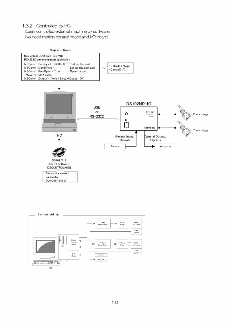
1.3.2 Controlled by PC Easily controlled external machine by software.
No need motion control board and I/O board.
Sensor Actuator
USBor
RS-232CX axis stage
Y axis stage
PC General Input:16points
General Output:12points
DS102Stepping Motor
Controller
DS102NR-IO
Use virtual COM port (Ex.:VB)RS-232C communication application
MSComm1.Settings = "9600,N,8,1" ' Set up the port MSComm1.CommPort = 1 ' Set up the port add. MSComm1.PortOpen = True ' Open the port ' Move to 100 X axies MSComm1.Output = "Axis1:Selsp 0:Goabs 100"
Original software
・Set up the system parametor・Operation check
・Cotrolled stage・ControlI I/O
DS102/112Control Software:DSCONTROL-WIN
MotionControlBoard
X AxisMotor driver
X AxisMotor
Guideball screw
LimitSwitch
Y AxisMotor Driver
Y AxiesMotor
Guideball screw
LimitSwitch
I/OBoard
Sensor
Actuator
PC
Former set-up
10
1.4 Accessories This included following goods. Please check when you open. If some parts missing, please let us
know.
・ DS102/DS112:1 PCS
・ Power cable(2m) :1 PCS(Only case of DS102)
・ CD-ROM(USB Device driver) :1PCS
・ Manual(this documents) :1PCS
The power cable of DS102 attachment is exclusively for this machine.
2.Set-up and example of use
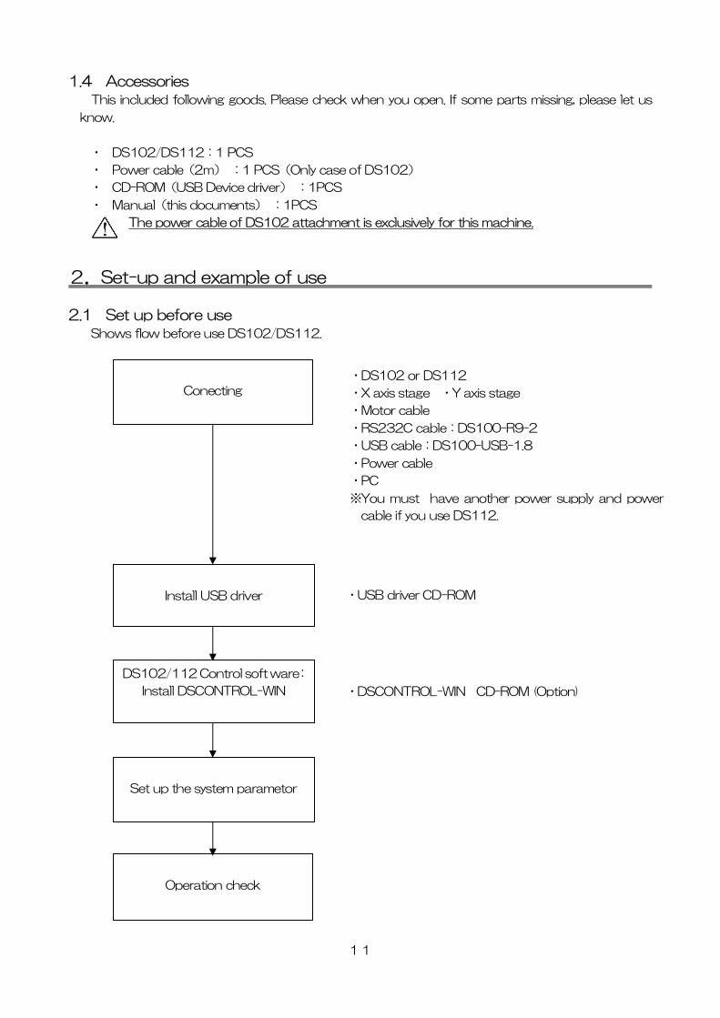
2.1 Set up before use Shows flow before use DS102/DS112.
Operation check
・DS102 or DS112
・X axis stage ・Y axis stage
・Motor cable
・RS232C cable:DS100-R9-2
・USB cable:DS100-USB-1.8
・Power cable
・PC
※You must have another power supply and power
cable if you use DS112.
・USB driver CD-ROM
・DSCONTROL-WIN CD-ROM (Option)
Set up the system parametor
DS102/112 Co rol soft ware:
Install DSCON ROL-WIN
nt
T
Install USB driver
Conecting
11
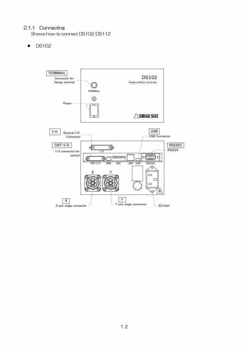
2.1.1 Connecting
Shows how to connect DS102/DS112
DS102
TERMINAL
DS102Stepping Motor Controller
Power
Connector for Handy terminal
TERMINAL
I/O connector forcontrol
RS232C
X axis stage connector
General I/O Connector
X Y
I/O
CNT-I/O EMS SW1 LINK USB RS232C
USB Connector
AC InletY axis stage connector
I/O
CNT-I/O
USB
RS232C
X Y
12
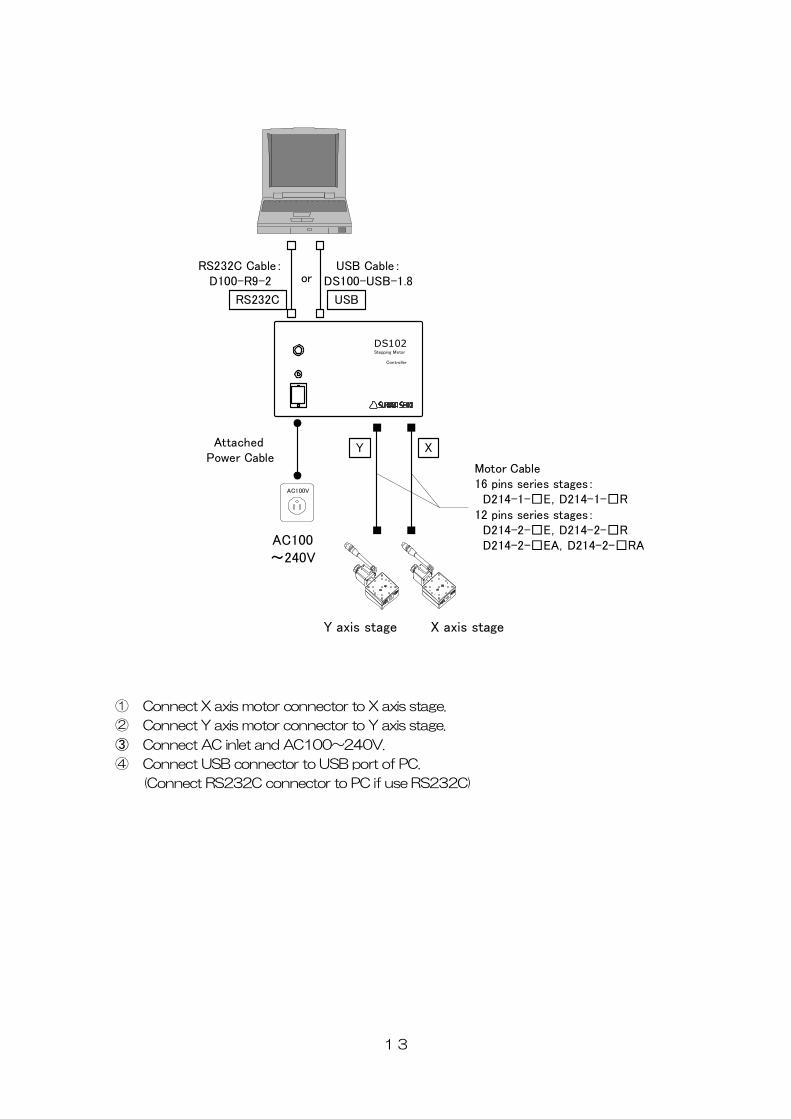
DS102Stepping Motor
Controller
X axis stageY axis stage
AC100V
AC100~240V
USB Cable:DS100-USB-1.8
USBRS232C
RS232C Cable:D100-R9-2 or
XY
Motor Cable16 pins series stages: D214-1-□E,D214-1-□R12 pins series stages: D214-2-□E,D214-2-□R D214-2-□EA,D214-2-□RA
Attached Power Cable
① Connect X axis motor connector to X axis stage.
② Connect Y axis motor connector to Y axis stage.
③ Connect AC inlet and AC100~240V.
④ Connect USB connector to USB port of PC.
(Connect RS232C connector to PC if use RS232C)
13
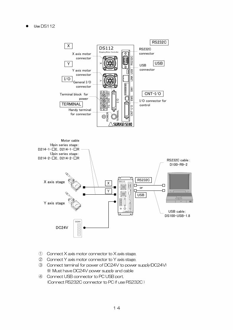
Use DS112
XY
TERM
INAL
PO
WER
+24
V
CN
T-I/
OEM
SSW
1LIN
KU
SB
RS232C
DS112
GN
DFG
I/O
Y axis motorconnector
Terminal block forpower
General I/Oconnector
Handy terminalfor connector
RS232Cconnector
USBconnector
I/O connector forcontrol
Stepping Motor Controller
I/O
CNT-I/O
USB
RS232CX
Y
TERMINAL
X axis motorconnector
X axis stage
Y axis stage
XY
DS112Stepping Motor ControllerX
Y
USB cable:DS100-USB-1.8
USB
RS232C
RS232C cable:D100-R9-2
or
Motor cable16pin series stage:
D214-1-□E,D214-1-□R12pin series stage:
D214-2-□E,D214-2-□R
DC24V
DC24V
① Connect X axis motor connector to X axis stage.
② Connect Y axis motor connector to Y axis stage.
③ Connect terminal for power of DC24V to power supply(DC24V)
※ Must have DC24V power supply and cable
④ Connect USB connector to PC USB port.
(Connect RS232C connector to PC if use RS232C )
14
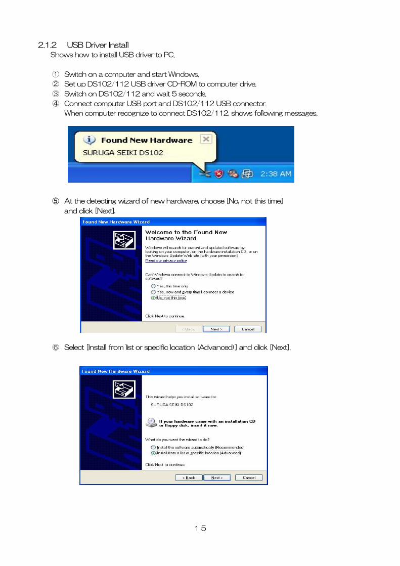
2.1.2 USB Driver Install
Shows how to install USB driver to PC.
① Switch on a computer and start Windows.
② Set up DS102/112 USB driver CD-ROM to computer drive.
③ Switch on DS102/112 and wait 5 seconds.
④ Connect computer USB port and DS102/112 USB connector.
When computer recognize to connect DS102/112, shows following messages.
⑤ At the detecting wizard of new hardware, choose [No, not this time]
and click [Next].
⑥ Select [Install from list or specific location (Advanced)] and click [Next].
15
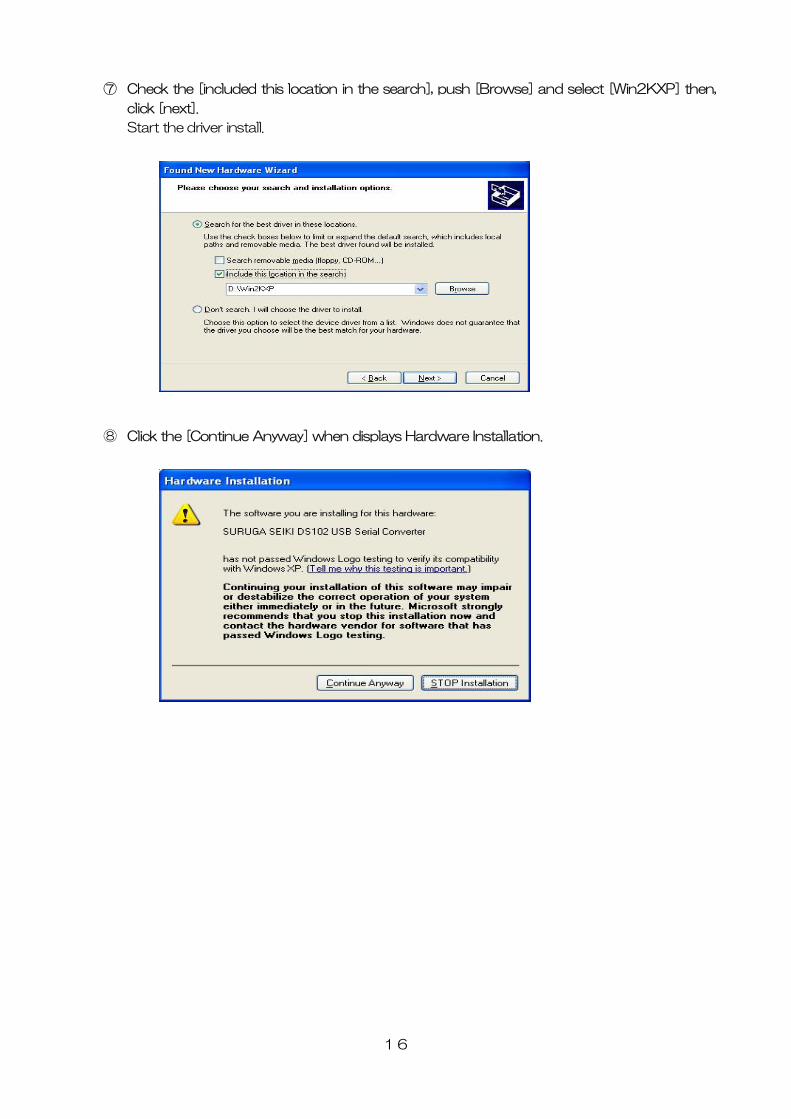
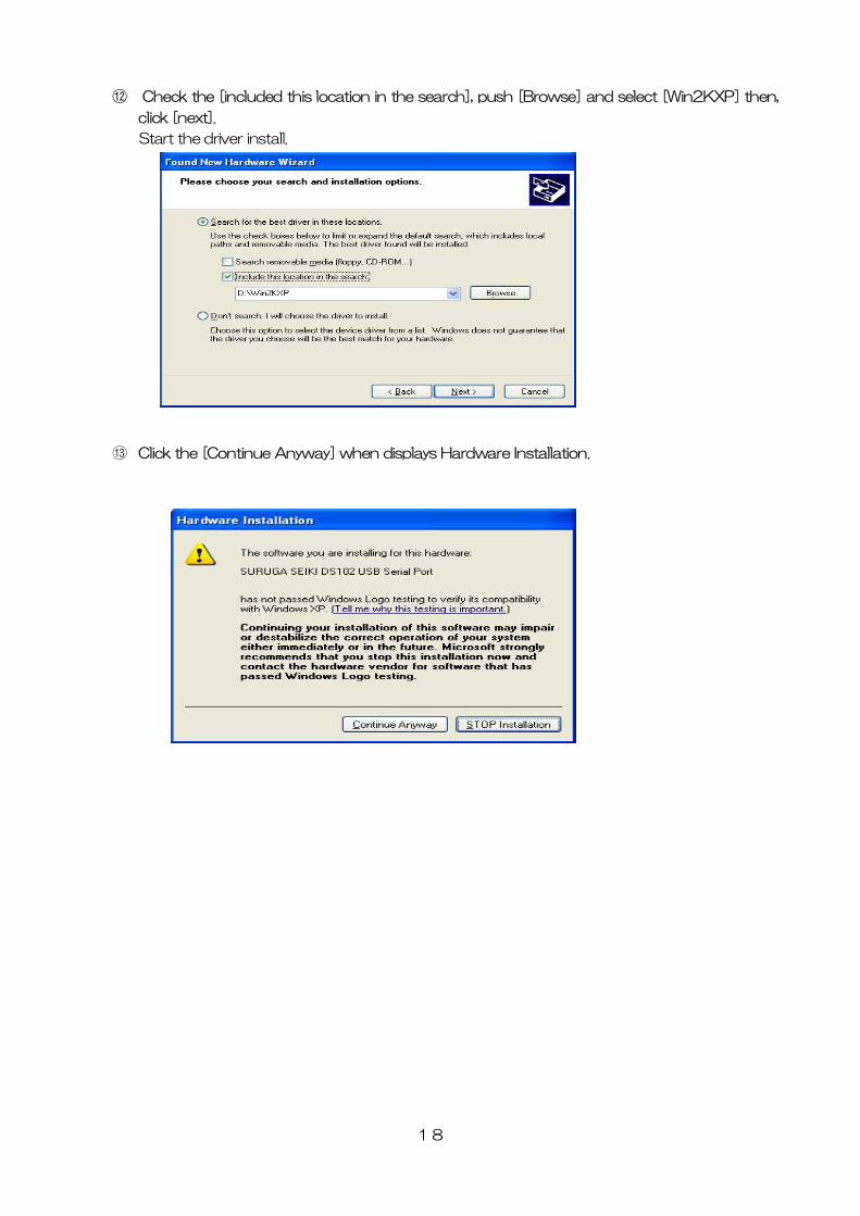
⑦ Check the [included this location in the search], push [Browse] and select [Win2KXP] then,
click [next].
Start the driver install.
⑧ Click the [Continue Anyway] when displays Hardware Installation.
16
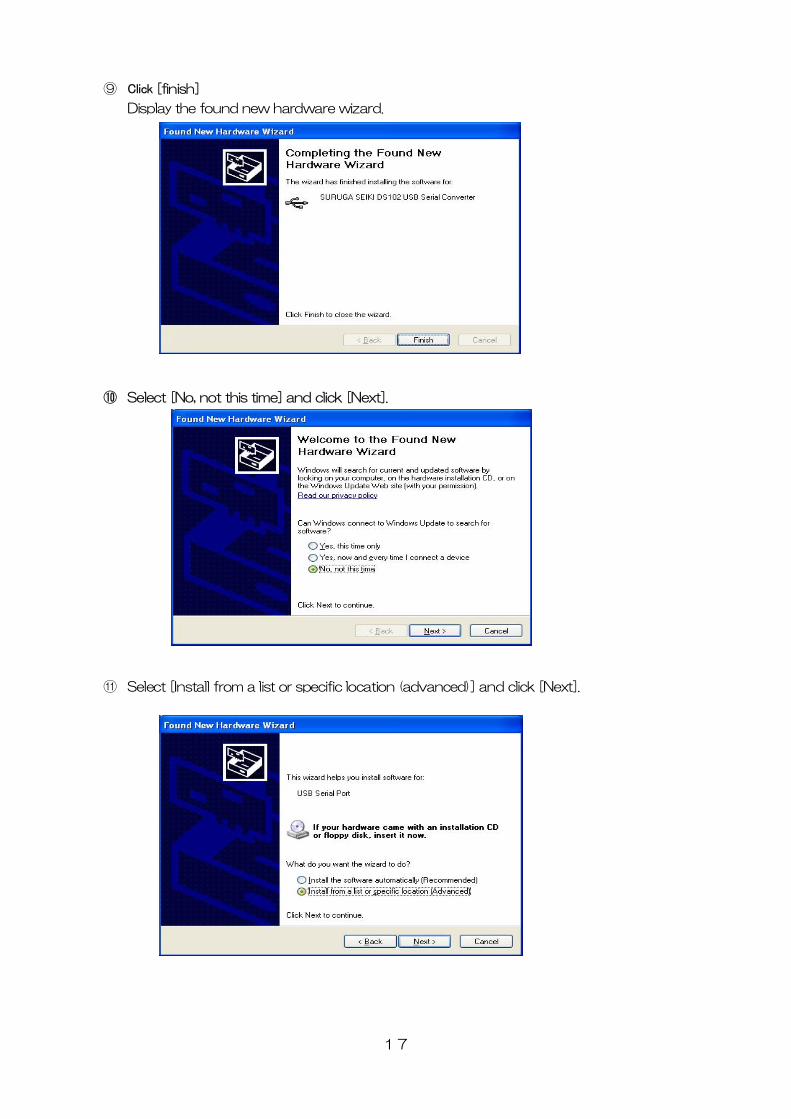
⑨ Click [finish]
Display the found new hardware wizard.
⑩ Select [No, not this time] and click [Next].
⑪ Select [Install from a list or specific location (advanced)] and click [Next].
17
⑫ Check the [included this location in the search], push [Browse] and select [Win2KXP] then,
click [next].
Start the driver install.
⑬ Click the [Continue Anyway] when displays Hardware Installation.
18
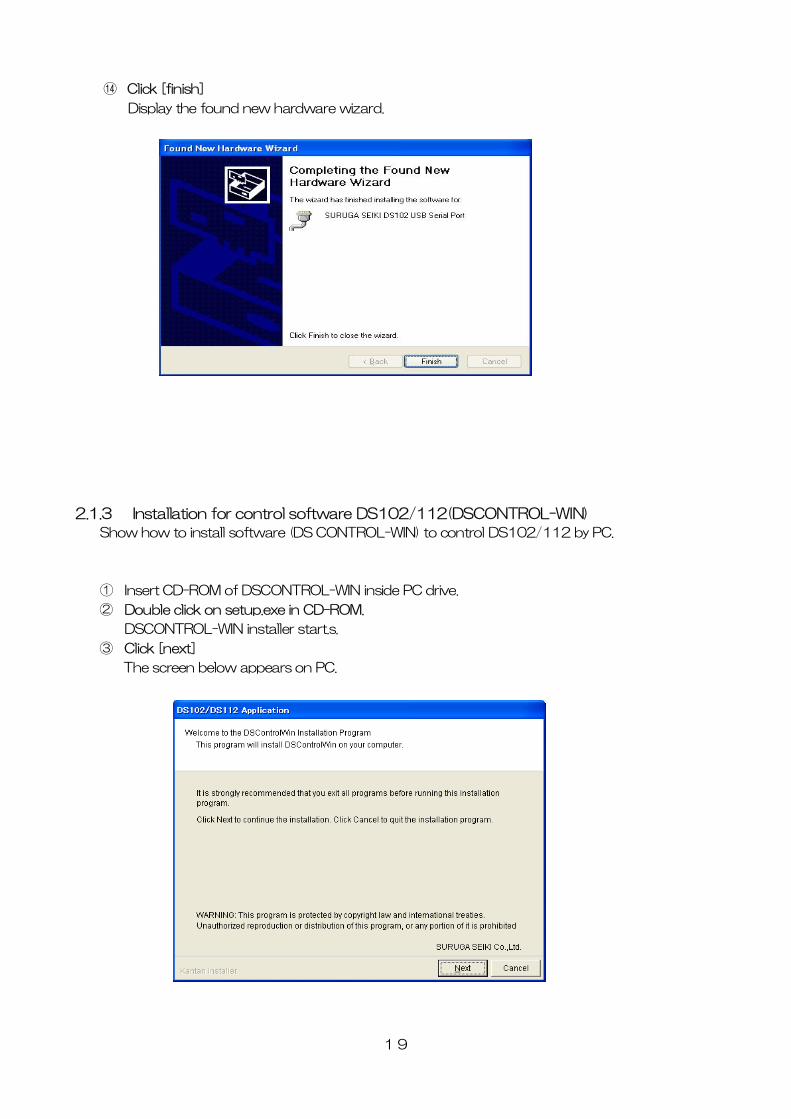
⑭ Click [finish]
Display the found new hardware wizard.
2.1.3 Installation for control software DS102/112(DSCONTROL-WIN)
Show how to install software (DS CONTROL-WIN) to control DS102/112 by PC.
① Insert CD-ROM of DSCONTROL-WIN inside PC drive.
② Double click on setup.exe in CD-ROM.
DSCONTROL-WIN installer start.s.
③ Click [next]
The screen below appears on PC.
19
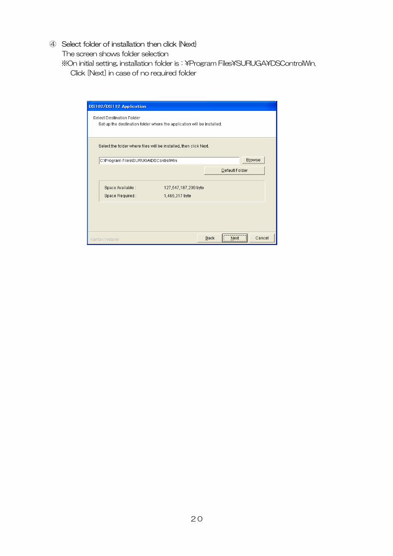
④ Select folder of installation then click {Next}
The screen shows folder selection
※On initial setting, installation folder is:\Program Files\SURUGA\DSControlWin.
Click [Next] in case of no required folder
20
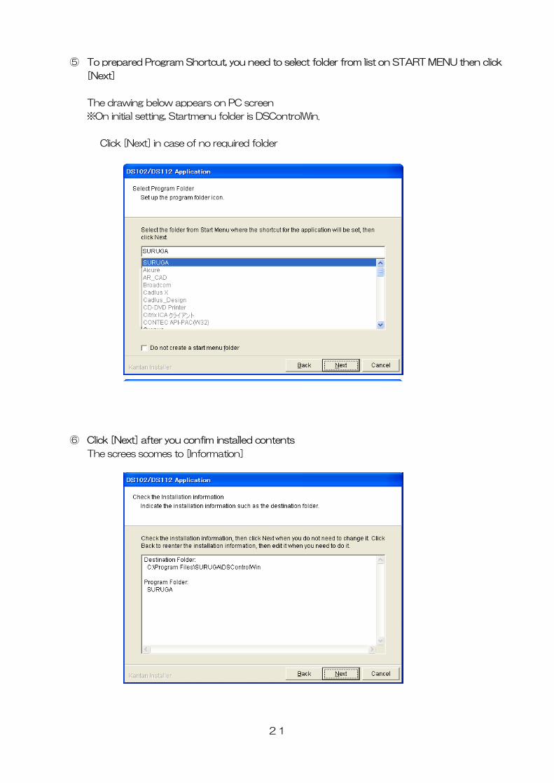
⑤ To prepared Program Shortcut, you need to select folder from list on START MENU then click
[Next]
The drawing below appears on PC screen
※On initial setting, Startmenu folder is DSControlWin.
Click [Next] in case of no required folder
⑥ Click [Next] after you confim installed contents
The screes scomes to [Information]
21
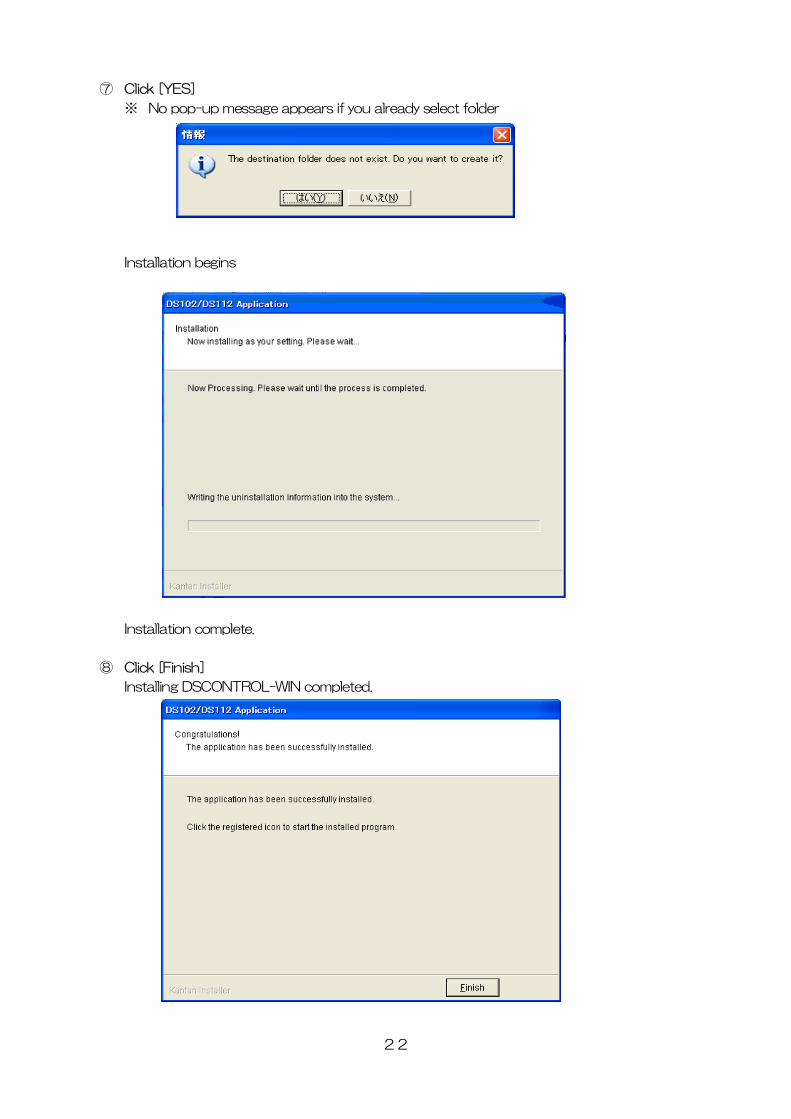
⑦ Click [YES]
※ No pop-up message appears if you already select folder
Installation begins
Installation complete.
⑧ Click [Finish]
Installing DSCONTROL-WIN completed.
22
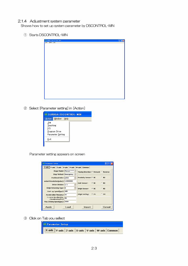
2.1.4 Adjustment system parameter
Shows how to set up system parameter by DSCONTROL-WIN
① Starts DSCONTROL-WIN
② Select [Parameter setting] in [Action]
Parameter setting appears on screen
③ Click on Tab you sellect
23
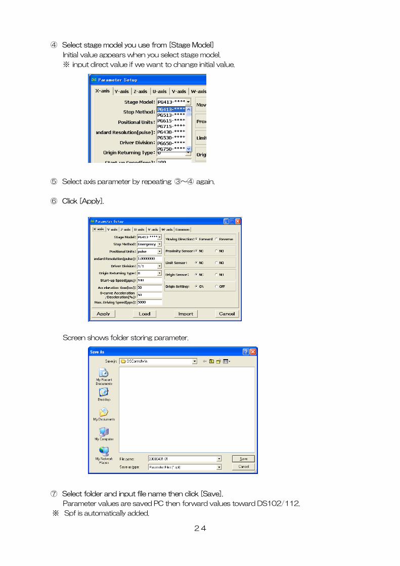
④ Select stage model you use from [Stage Model]
Initial value appears when you select stage model.
※ input direct value if we want to change initial value.
⑤ Select axis parameter by repeating ③~④ again.
⑥ Click [Apply].
Screen shows folder storing parameter.
⑦ then click [Save].
Parameter values are saved PC then forward values toward DS102/112.
※ Spf is automatically added.
Select folder and input file name
24
25
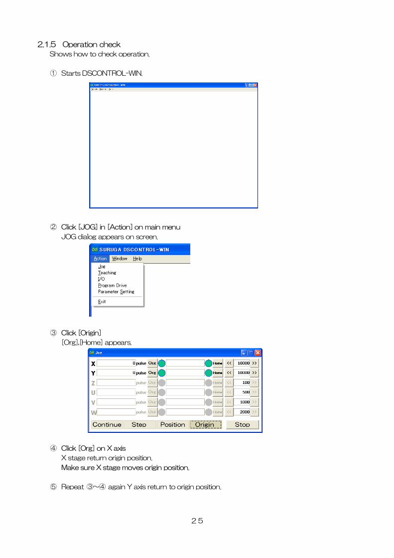
2.1.5 Operation check
Shows how to check operation.
① Starts DSCONTROL-WIN.
② Click [JOG] in [Action] on main menu
JOG dialog appears on screen.
③ Click [Origin]
[Org],[Home] appears.
④ Click [Org] on X axis
X stage return origin position.
Make sure X stage moves origin position.
⑤ Repeat ③~④ again Y axis return to origin position.
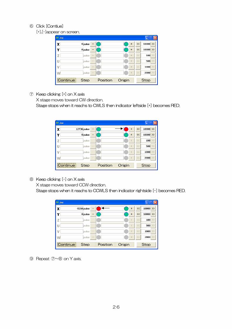
⑥ Click [Contiue]
[+],[-]appear on screen.
⑦ Keep clicking [+] on X axis
X stage moves toward CW direction.
Stage stops when it reachs to CWLS then indicator leftside [+] becomes RED.
⑧ Keep clicking [-] on X axis
X stage moves toward CCW direction.
Stage stops when it reachs to CCWLS then indicator rightside [-] becomes RED.
⑨ Repeat ⑦~⑧ on Y axis.
26
27
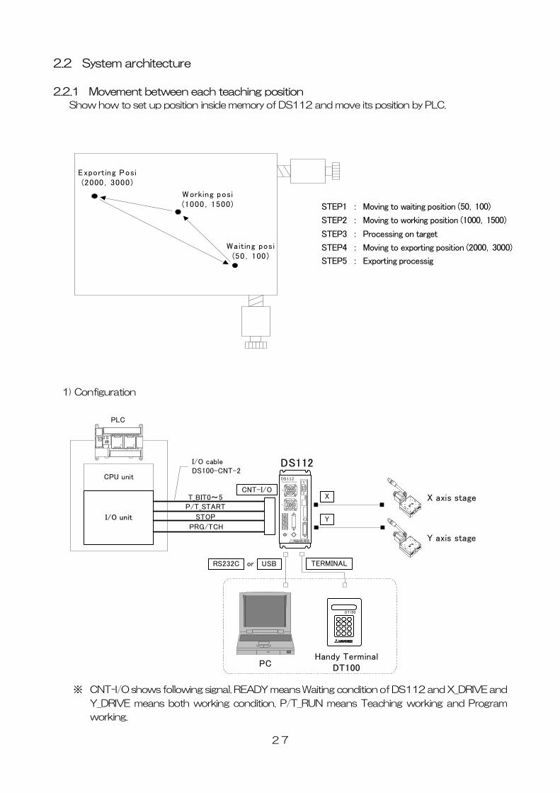
2.2 ystem architecture
2.2.1 Movement between each teaching position
Sh w how to set up position inside memory of DS112 and move its position by PLC.
1) Configuration
※ of DS112 and X_DRIVE and
Y_DRIVE means both working condition. P/T_RUN means Teaching working and Program
S
o
Waiting posi(50,100)
W orking posi(1000,1500)
Exporting Posi(2000,3000)
X axis stage
CPU unit
I/O unit
Y axis stage
PLC
XY
DS112Stepping Motor Control ler
DS112
T_BIT0~5P/T_START
STOP
PRG/TCH
CNT-I/O
I/O cableDS100-CNT-2
PC
DT100
Handy TerminalDT100
USB TERMINAL
X
Y
RS232C or
STEP1 : Moving to waiting position (50,100)
STEP2 : Moving to working position (1000,1500)
STEP3 : Processing on target
STEP4 : Moving to exporting position (2000,3000)
STEP5 : Exporting processig
CNT-I/O shows following signal. READY means Waiting condition
working.
28
2) Mov
W emor ed insid s teaching points, 00, 01, 02,
P
Set up 00 among T_BIT0~5, press P/T_START <STEP1>
Set up 01 among T_BIT0~5, press P/T_START <STEP2>
ait unitl woring on target is done <STEP3>
g T_BIT0~5, press P/T_START <STEP4>
<STEP5>
3) Con t
C
P
2C to PC when using RS232C)
② on
③ on
④ on Y stage
⑤ on
On control I/O,
P/T_START:Signal to move to teaching point
STOP:Stop signal for all axes
PRG/TCH:program mode / teaching point mode
※ T_BIT0~2:combined use for program selection
ement summary
aiting, working and exporting position m iz e DS112 a
LC appoints each points then make state move to each points.
①
②
③ W
④ Set up 02 amon
⑤ Wait until exporting is done
nec
onnect to DS112
C is used when setting or editing teaching point
① Connect USB to PC USB port
(Connect RS23
C nect handy terminal to DS112
C nect X axis motor connector to X stage
C nect Y axia motor connector to
C nect control I/O connector to PLC I/O unit
T_BIT0~5:Appoint teaching point
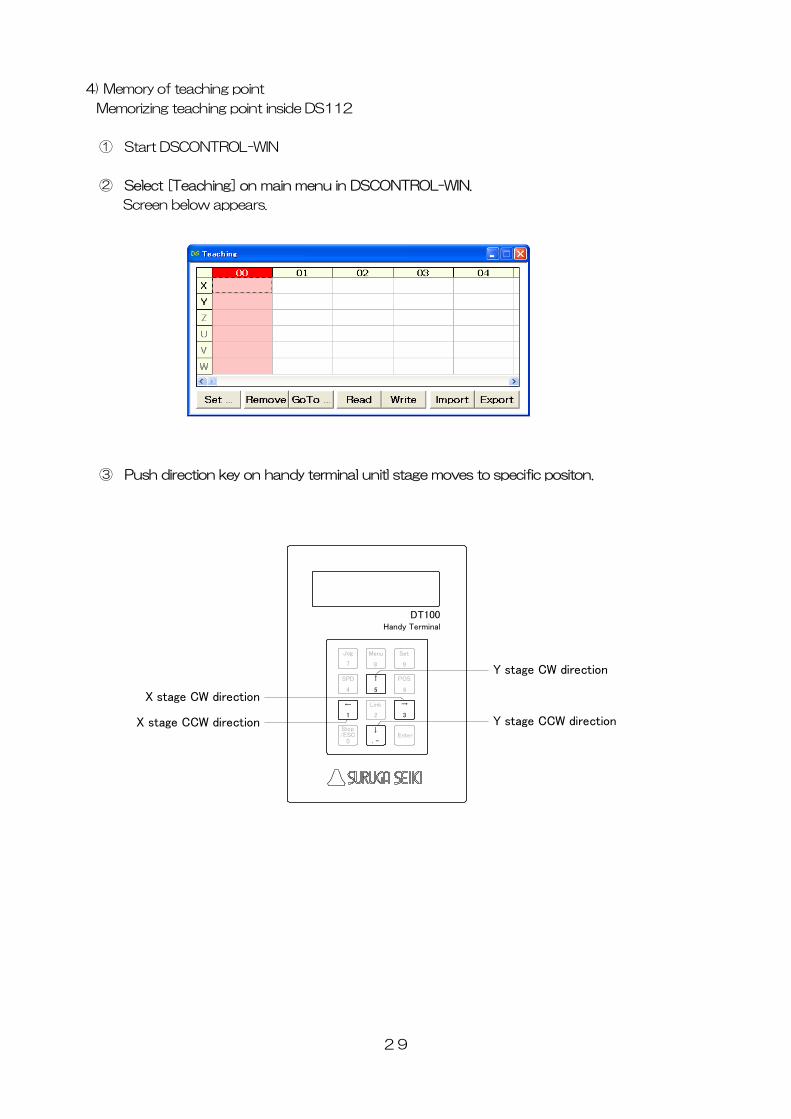
4) Memory of teaching point
Memorizing teaching point inside DS112
① Start DSCONTROL-WIN
② Select [Teaching] on main menu in DSCONTROL-WIN.
Screen below appears.
③ Push direction key on handy terminal unitl stage moves to specific positon.
Jog
7
Menu
8
Set
9
SPD
4
↑
5
POS
6
←
1
Link
2
→
3
Stop
0/ESC
DT100Handy Terminal
↓
.-Enter
X stage CCW direction
X stage CW direction
Y stage CCW direction
Y stage CW direction
29
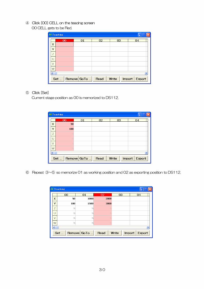
④ Click [00] CELL on the teacing screen
00 CELL gets to be Red.
⑤ Click [Set]
Current stage position as 00 is memorized to DS112.
⑥ Repeat ③~⑤ so memorize 01 as working position and 02 as exporting position to DS112.
30
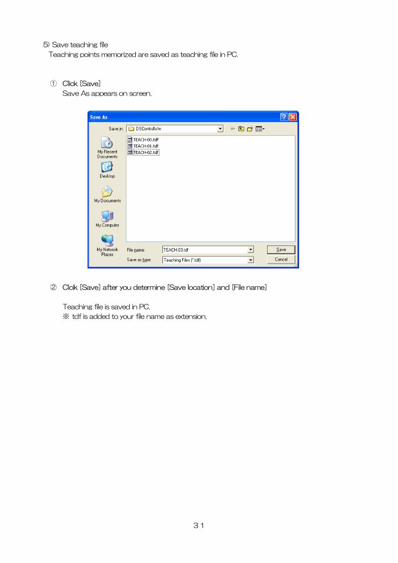
5) Save teaching file
Teaching points memorized are saved as teaching file in PC.
① Click [Save]
Save As appears on screen.
② Clcik [Save] after you determine [Save location] and [File name]
Teaching file is saved in PC.
※ tdf is added to your file name as extension.
31
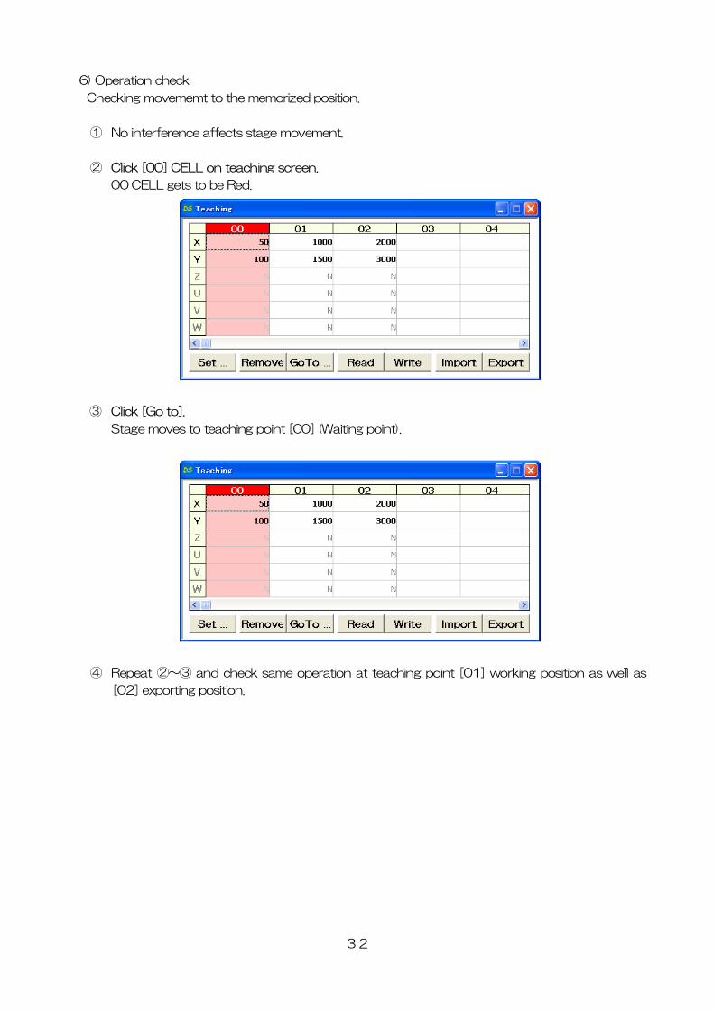
6) Operation check
Checking movememt to the memorized position.
① No interference affects stage movement.
② Click [00] CELL on teaching screen.
00 CELL gets to be Red.
③ Click [Go to].
Stage moves to teaching point [00] (Waiting point).
④ Repeat ②~③ and check same operation at teaching point [01] working position as well as
[02] exporting position.
32
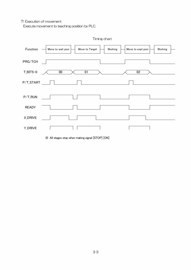
7) Execution of movement
Execute movement to teaching position by PLC.
33
Timing chart
PRG/TCH
T_BIT5-0
P/T_START
Function
00 01 02
Move to wait posi Move to Target Working Move to expt posi Working
P/T_RUN
READY
X_DRIVE
Y_DRIVE
※ All stages stop when making signal [STOP] [ON]
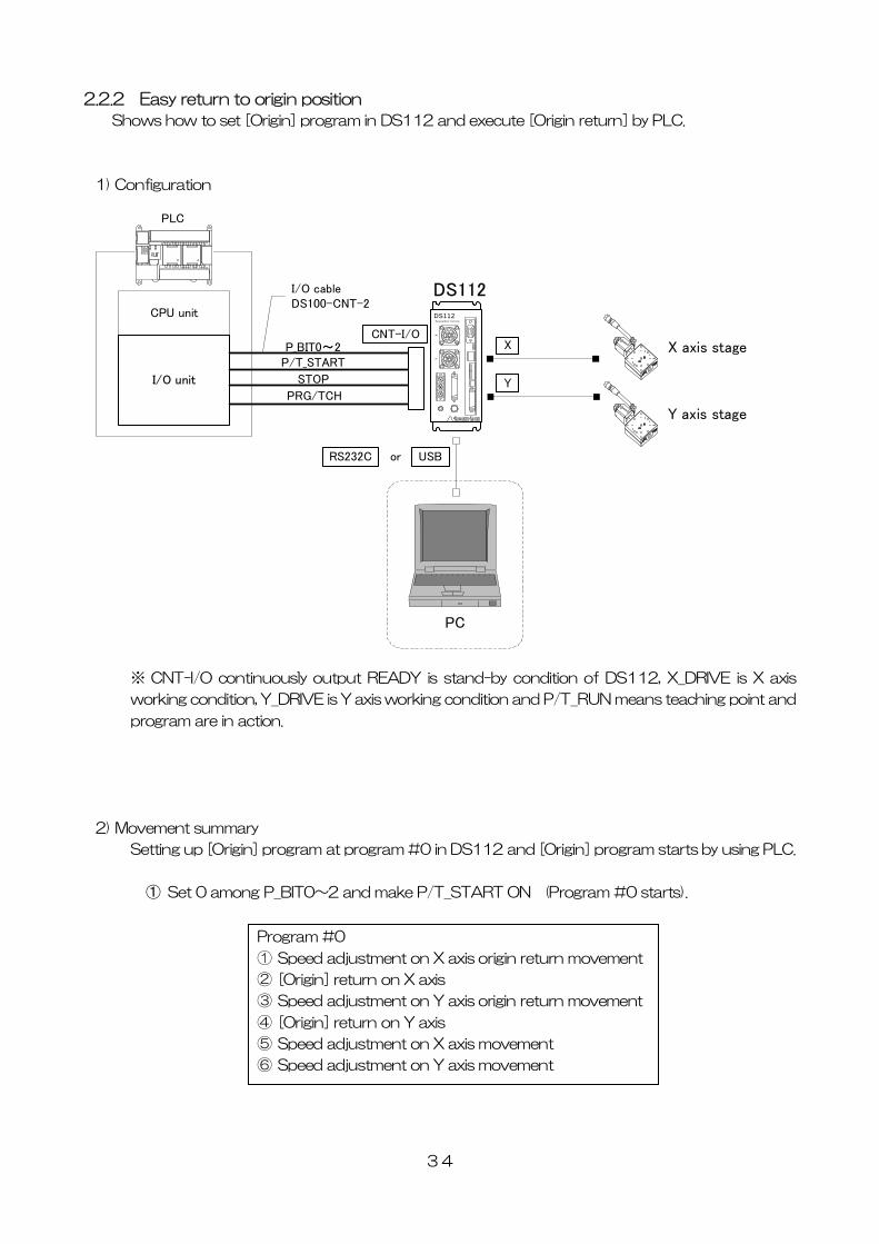
2.2.2 Easy return to origin position
Shows how to set [Origin] program in DS112 and execute [Origin return] by PLC.
1) Configuration
CPU unit
I/O unit
X axis stage
Y axis stage
PLC
XY
DS112Stepping Motor Contro ller
DS112
P_BIT0~2P/T_START
STOP
PRG/TCH
CNT-I/O
I/O cableDS100-CNT-2
X
Y
PC
USBRS232C or
※ CNT-I/O continuously output READY is stand-by condition of DS112, X_DRIVE is X axis
working condition, Y_DRIVE is Y axis working condition and P/T_RUN means teaching point and
program are in action.
2) Movement summary
Setting up [Origin] program at program #0 in DS112 and [Origin] program starts by using PLC.
① Set 0 among P_BIT0~2 and make P/T_START ON (Program #0 starts).
Program #0
① Speed adjustment on X axis origin return movement
② [Origin] return on X axis
③ Speed adjustment on Y axis origin return movement
④ [Origin] return on Y axis
⑤ Speed adjustment on X axis movement
⑥ Speed adjustment on Y axis movement
34
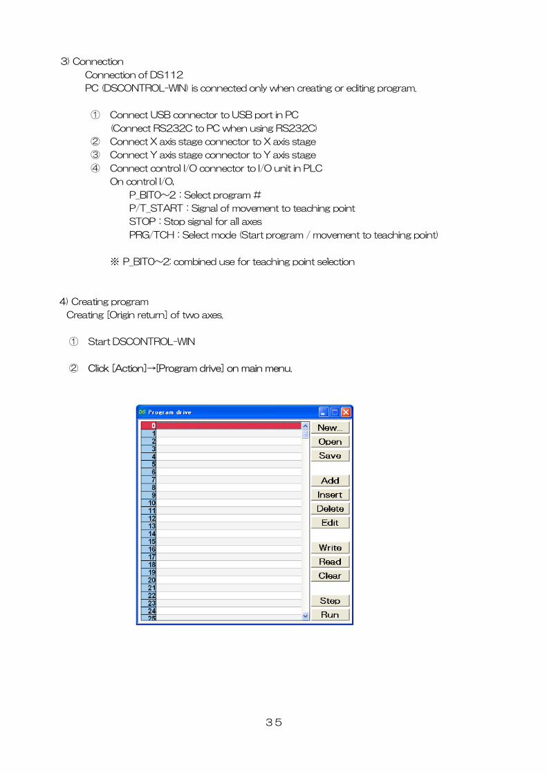
3) Connection
Connection of DS112
PC (DSCONTROL-WIN) is connected only when creating or editing program.
① Connect USB connector to USB port in PC
(Connect RS232C to PC when using RS232C)
② Connect X axis stage connector to X axis stage
③ Connect Y axis stage connector to Y axis stage
④ Connect control I/O connector to I/O unit in PLC
On control I/O,
P_BIT0~2:Select program #
P/T_START:Signal of movement to teaching point
STOP:Stop signal for all axes
PRG/TCH:Select mode (Start program / movement to teaching point)
※ P_BIT0~2: combined use for teaching point selection
4) Creating program
Creating [Origin return] of two axes.
① Start DSCONTROL-WIN
② Click [Action]→[Program drive] on main menu.
35
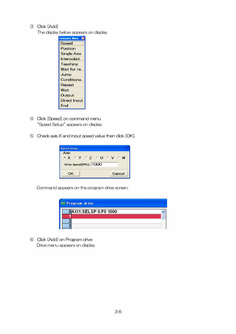
③ Click [Add]
The display below appears on display.
④
Speed Setup” appears on display.
⑤ heck axis X and input speed value then click [OK].
Click [Speed] on command menu
“
C
Command appears on the program drive screen.
⑥ Click [Add] on Program drive
Drive menu appears on display.
36
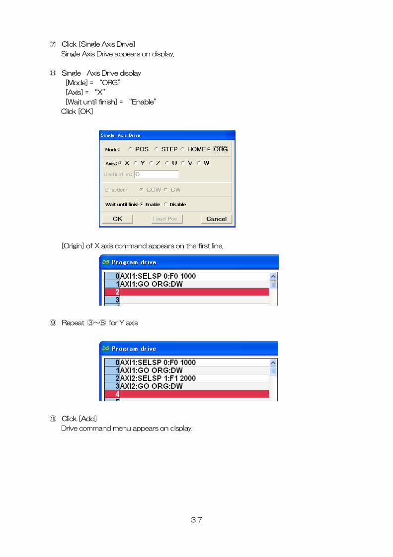
⑦ Click [Single Axis Drive]
Single Axis Drive appears on display.
⑧ Single Axis Drive display
[Mode] = “ORG”
[Axis] = “X”
[Wait until finish] = “Enable”
Click [OK]
[Origin] of X axis command appears on the first line.
⑨ Repeat ③~⑧ for Y axis
⑩ Click [Add]
Drive command menu appears on display.
37
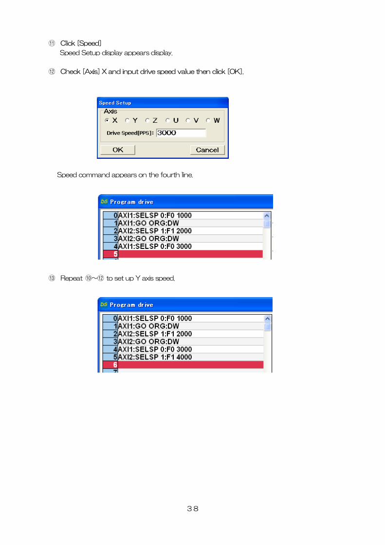
⑪ Click [Speed]
Speed Setup display appears display.
⑫ Check [Axis] X and input drive speed value then click [OK].
Speed command appears on the fourth line.
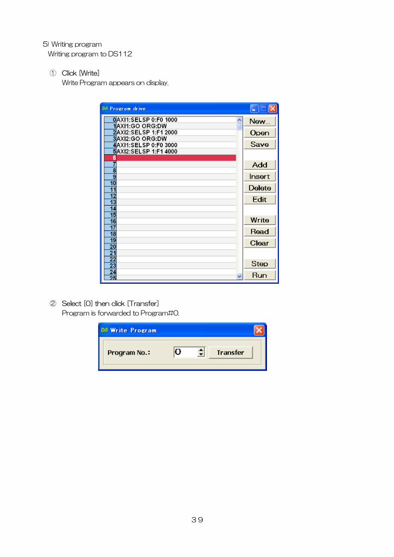
⑬ Repeat ⑩~⑫ to set up Y axis speed.
38
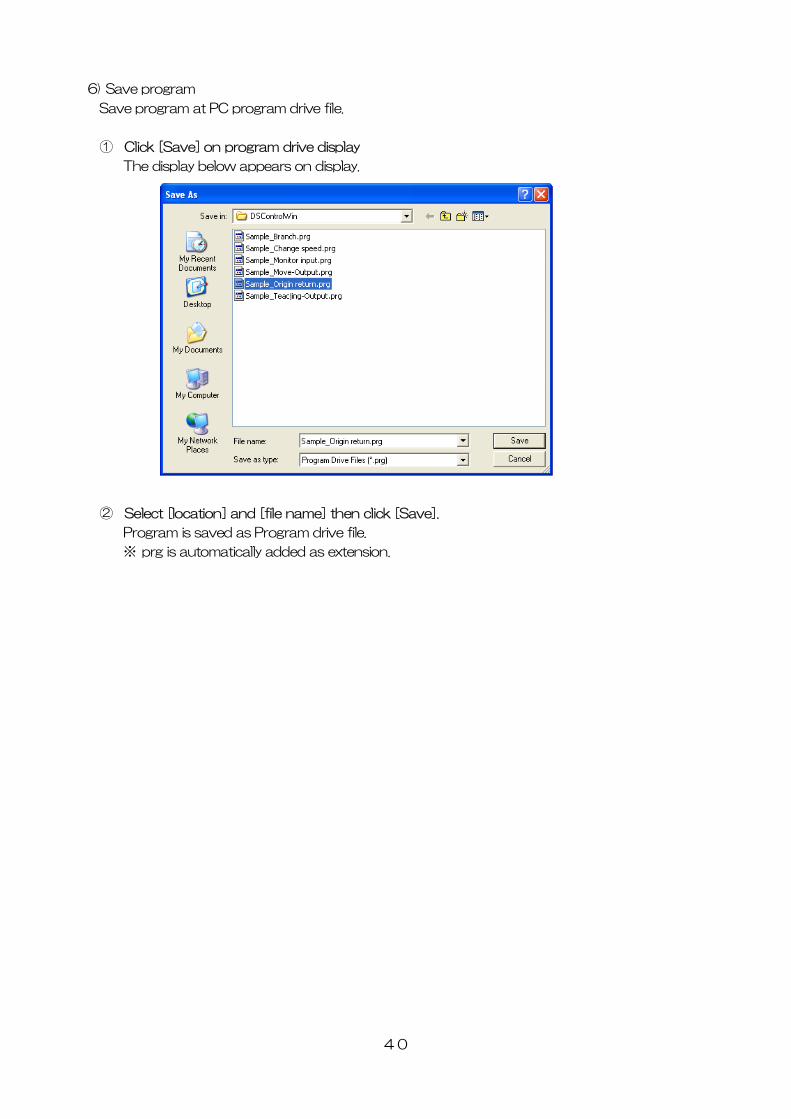
5) Writing program
Writing program to DS112
① Click [Write]
Write Program appears on display.
② Select [0] then click [Transfer]
Program is forwarded to Program#0.
39
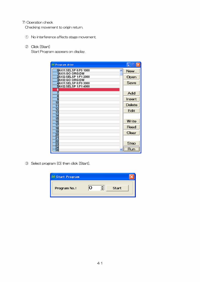
6) Save program
Save program at PC program drive file.
① Click [Save] on program drive display
The display below appears on display.
② Select [location] and [file name] then click [Save].
Program is saved as Program drive file.
※ prg is automatically added as extension.
40
7) Operation check
Checking movement to origin return.
① No interference affects stage movement.
② Click [Start]
Start Program appears on display.
③ Select program [0] then click [Start].
41
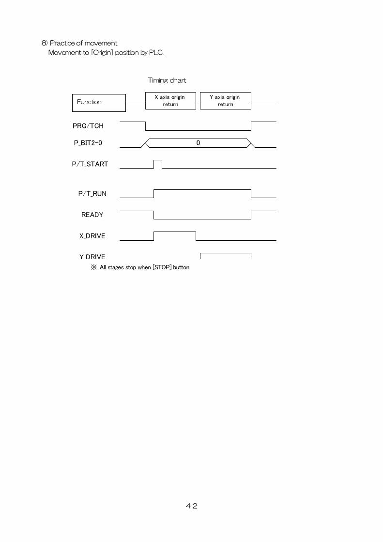
8) Practice of movement
Movement to [Origin] position by PLC.
42
Timing chart
PRG/TCH
P_BIT2-0
P/T_START
動作
0
X axis origin return
Y axis origin return
P/T_RUN
READY
X_DRIVE
Y DRIVE
Function
※ All stages stop when [STOP] button
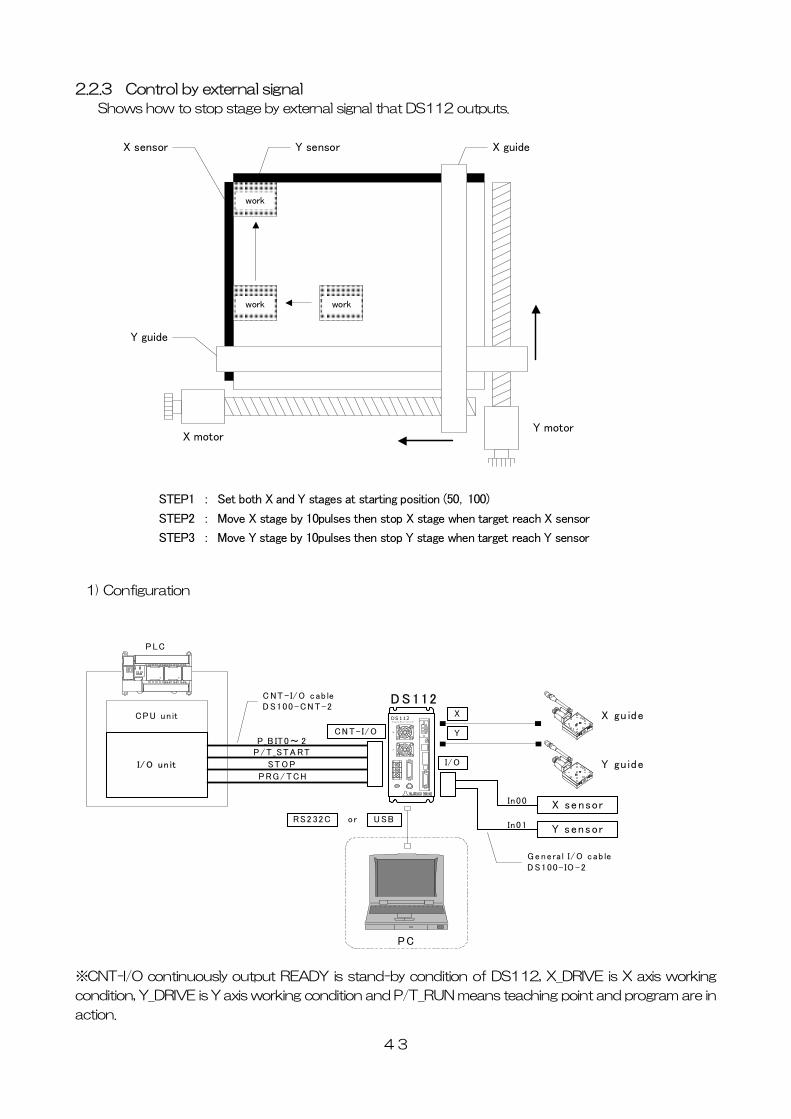
2.2.3 Control by external signal
Shows how to stop stage by external signal that DS112 outputs.
X motorY motor
workwork
work
X sensor Y sensor X guide
Y guide
STEP1 : Set both X and Y stages at starting position (50,100)
STEP2 : Move X stage by 10pulses then stop X stage when target reach X sensor
STEP3 : Move Y stage by 10pulses then stop Y stage when target reach Y sensor
1) Configuration
CPU un it
I/ O un it
X gu ide
Y gu ide
PLC
XY
DS 112S teppi ng M oto r Cont rol ler
D S 112
P_B IT0~ 2P/T _STA RT
ST O P
PRG/ TCH
CN T- I/O
C NT - I/O cab leDS100 -CN T-2
I/O
X sensor
Y sensor
In00
In01
Ge nera l I/O cab leDS100- IO -2
PC
U SBRS2 32C or
X
Y
※CNT-I/O continuously output READY is stand-by condition of DS112, X_DRIVE is X axis working
condition, Y_DRIVE is Y axis working condition and P/T_RUN means teaching point and program are in
action.
43
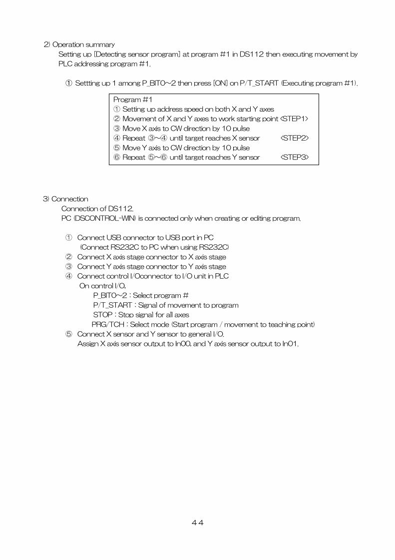
2) Operation summary
Setting up [Detecting sensor program] at program #1 in DS112 then executing movement by
PLC addressing program #1.
① Settting up 1 among P_BIT0~2 then press [ON] on P/T_START (Executing program #1).
Program #1
① Setting up address speed on both X and Y axes
② Movement of X and Y axes to work starting point <STEP1>
③ Move X axis to CW direction by 10 pulse
④ Repeat ③~④ until target reaches X sensor <STEP2>
⑤ Move Y axis to CW direction by 10 pulse
⑥ Repeat ⑤~⑥ until target reaches Y sensor <STEP3>
3) Connection
Connection of DS112.
PC (DSCONTROL-WIN) is connected only when creating or editing program.
① Connect USB connector to USB port in PC
(Connect RS232C to PC when using RS232C)
② Connect X axis stage connector to X axis stage
③ Connect Y axis stage connector to Y axis stage
④ Connect control I/Oconnector to I/O unit in PLC
On control I/O,
P_BIT0~2:Select program #
P/T_START:Signal of movement to program
STOP:Stop signal for all axes
PRG/TCH:Select mode (Start program / movement to teaching point)
⑤ Connect X sensor and Y sensor to general I/O.
Assign X axis sensor output to In00, and Y axis sensor output to In01.
44
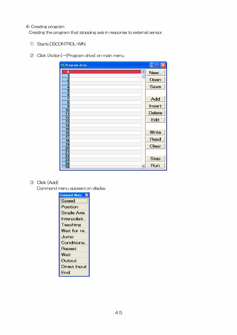
4) Creating program
Creating the program that stopping axis in response to external sensor.
① Starts DSCONTROL-WIN.
② Click [Action]→[Program drive] on main menu.
③ Click [Add]
Command menu appears on display.
45
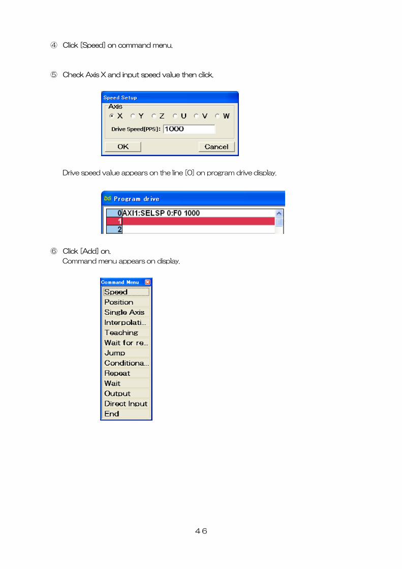
④ Click [Speed] on command menu.
⑤ Check Axis X and input speed value then click.
Drive speed value appears on the line [0] on program drive display.
⑥ Click [Add] on.
Command menu appears on display.
46
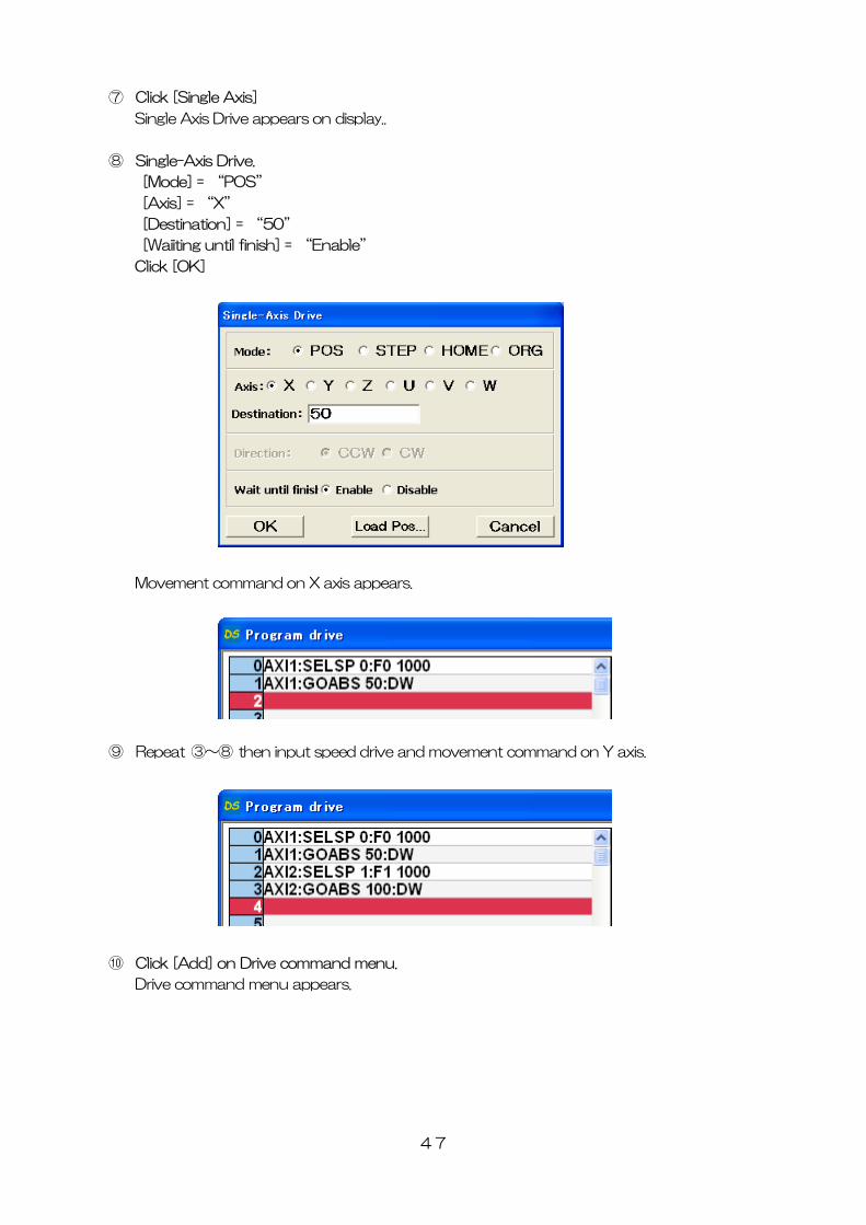
⑦ Click [Single Axis]
Single Axis Drive appears on display..
⑧ Single-Axis Drive.
[Mode] = “POS”
[Axis] = “X”
[Destination] = “50”
[Waiiting until finish] = “Enable”
Click [OK]
Movement command on X axis appears.
⑨ Repeat ③~⑧ then input speed drive and movement command on Y axis.
⑩ Click [Add] on Drive command menu.
Drive command menu appears.
47
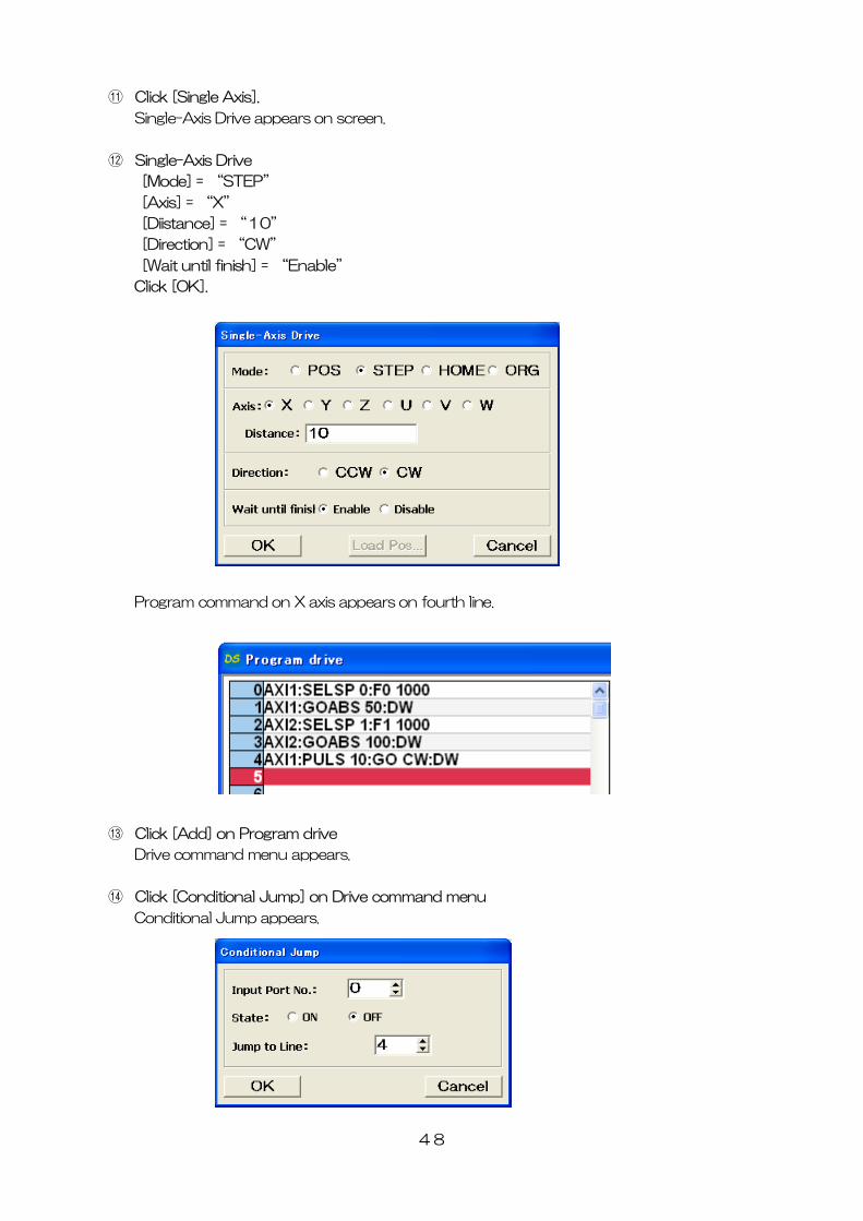
⑪ Click [Single Axis].
Single-Axis Drive appears on screen.
⑫ Single-Axis Drive
[Mode] = “STEP”
[Axis] = “X”
[Diistance] = “10”
[Direction] = “CW”
[Wait until finish] = “Enable”
Click [OK].
ppears on fourth line. Program command on X axis a
⑬ Click [Add] on Program drive
Drive command menu appears.
⑭ Click [Conditional Jump] on Drive command menu
Conditional Jump appears.
48
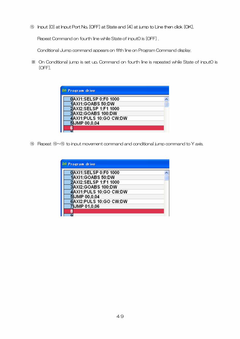
⑮ Input [0] at Input Port No, [OFF] at State and [4] at jump to Line then click [OK].
Repeat Command on fourth line while State of input0 is [OFF] .
Conditional Jump command appears on fifth line on Program Command display.
※ On Conditional jump is set up, Command on fourth line is repeated while State of input0 is
[OFF].
⑯ Repeat ⑩~⑮ to input movement command and conditional jump command to Y axis.
49
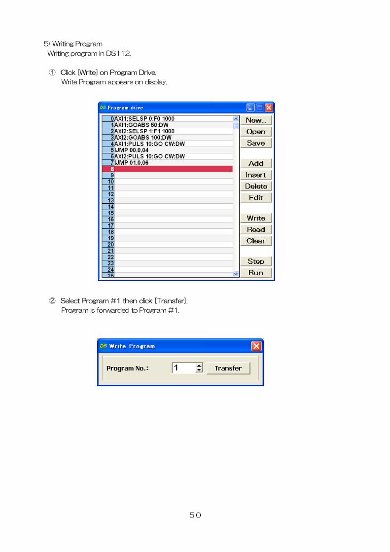
5) Writing Program
Writing program in DS112.
① Click [Write] on Program Drive.
Write Program appears on display.
② Select Program #1 then click [Transfer].
Program is forwarded to Program #1.
50
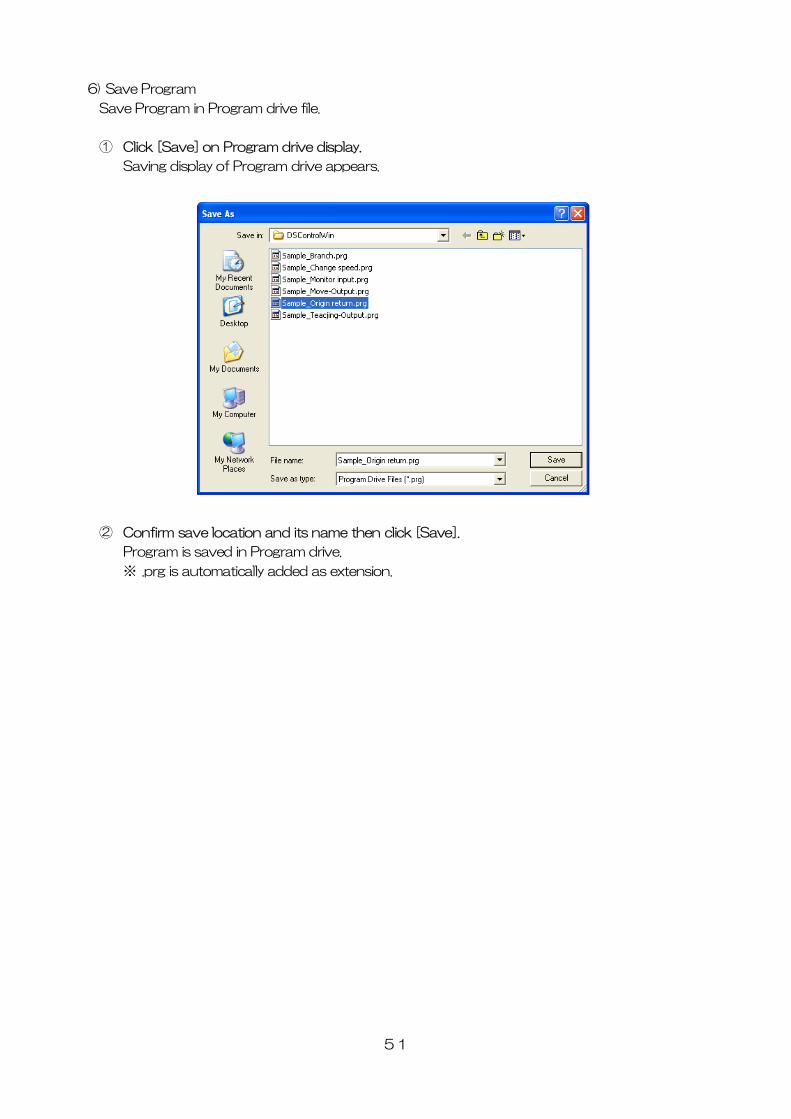
6) Save Program
Save Program in Program drive file.
① Click [Save] on Program drive display.
Saving display of Program drive appears.
② Confirm save location and its name then click [Save].
Program is saved in Program drive.
※ .prg is automatically added as extension.
51
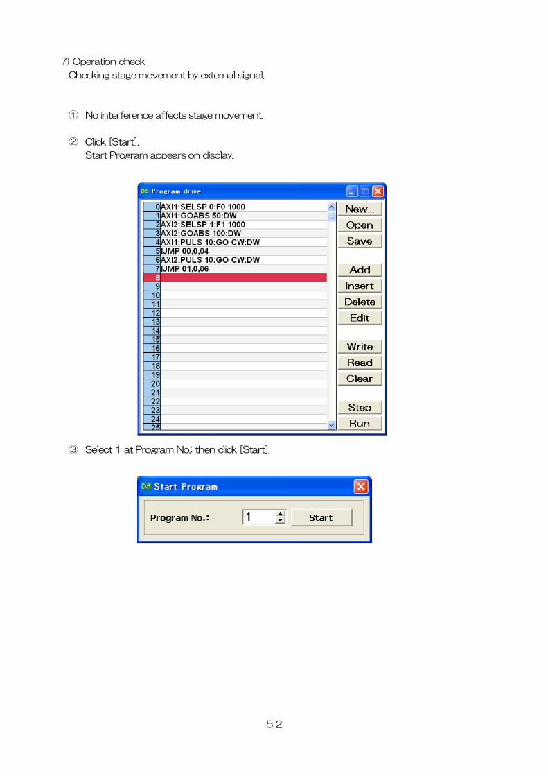
7) Operation check
Checking stage movement by external signal.
① No interference affects stage movement.
② Click [Start].
Start Program appears on display.
③ Select 1 at Program No.: then click [Start].
52
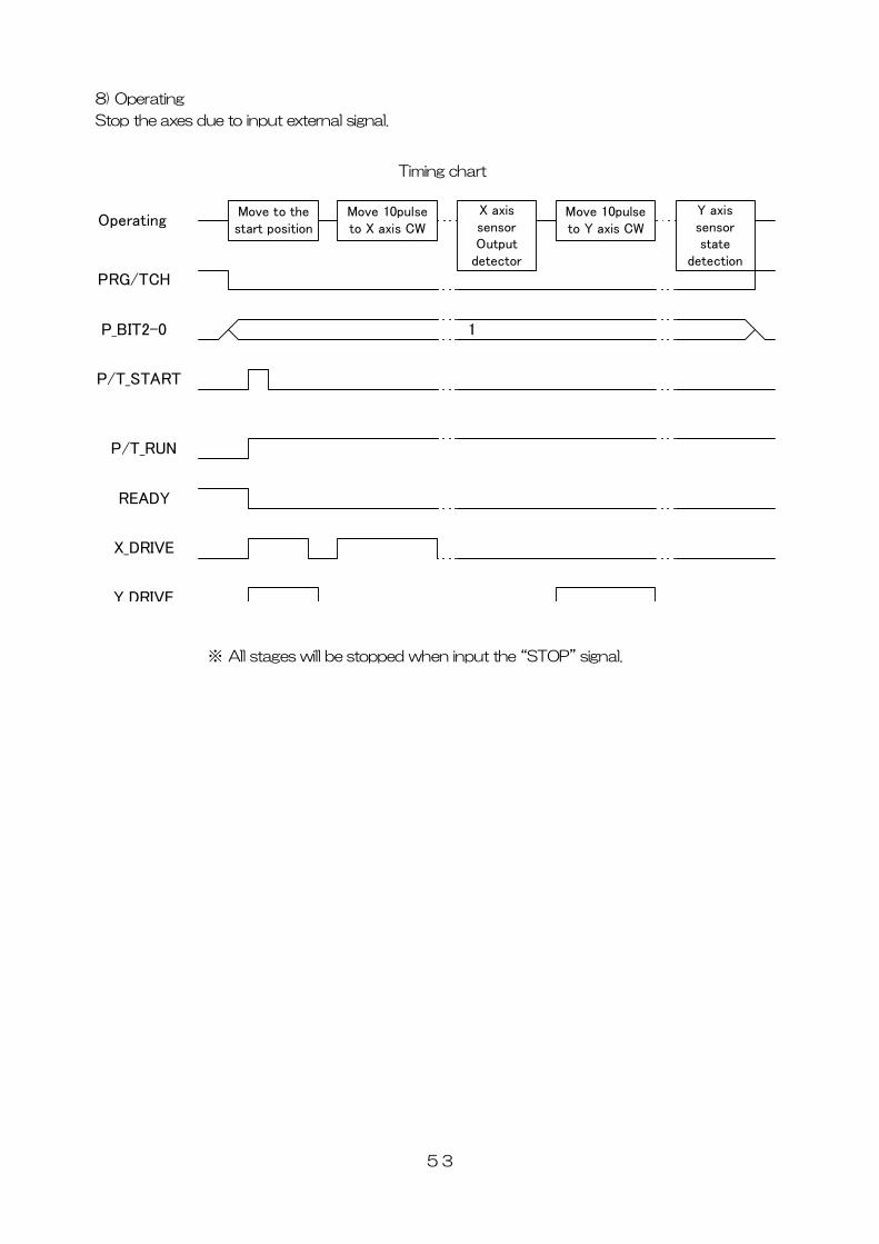
8) Operating
Stop the axes due to input external signal.
53
Timing chart
Move to thestart position
Move 10pulseto X axis CW
X axissensorOutput
detector
Move 10pulseto Y axis CW
Y axissensorstate
detection
PRG/TCH
※ All stages will be stopped when input the “STOP” signal.
P_BIT2-0
T_START
erating
1
Op
P/
P/T_RUN
READY
X_DRIVE
Y DRIVE
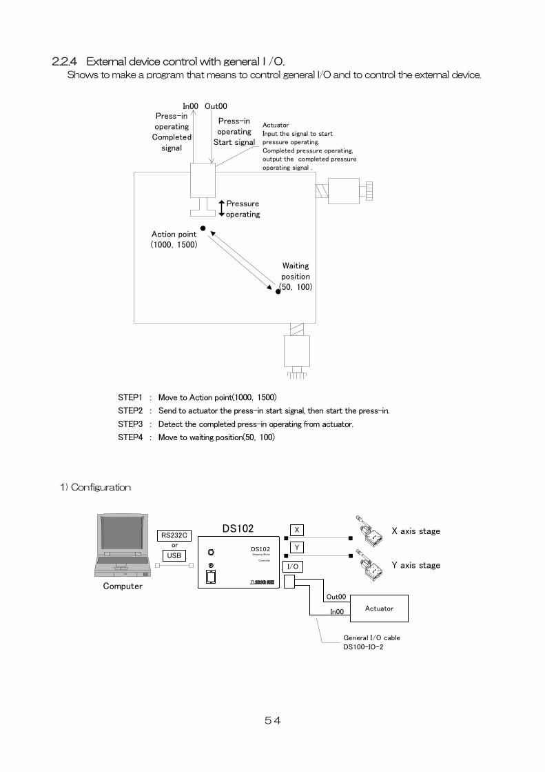
2.2.4 External device control with generalI/O.
Shows to make a program that means to control general I/O and to control the external device.
Waitingposition(50,100)
Action point(1000,1500)
ActuatorInput the signal to startpressure operating.Completed pressure operating,output the completed pressureoperating signal .
Pressureoperating
Out00In00
Press-inoperating
Start signal
Press-inoperatingCompleted
signal
54
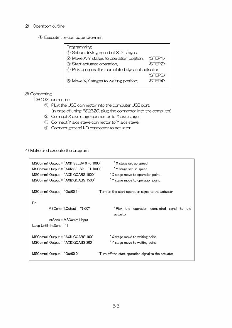
1) Configuration
X axis stage
Y axis stageI/O
Actuator
Out00
In00
General I/O cableDS100-IO-2
Computer
DS102Stepping Motor
Controller
DS102 X
YUSB
RS232C
or
STEP1 : Move to Action point(1000,1500)
STEP2 : Send to actuator the press-in start signal, then start the press-in.
STEP3 : Detect the completed press-in operating from actuator.
STEP4 : Move to waiting position(50,100)
2) Operation outline
① Execute the computer program.
Programming
① Set up driving speed of X, Y stages.
② Move X, Y stages to operation position. <STEP1>
③ Start actuator operation. <STEP2>
④ Pick up operation completed signal of actuator.
<STEP3>
⑤ Move X,Y stages to waiting position. <STEP4>
3) Connecting
DS102 connection
① Plug the USB connector into the computer USB port.
(In case of using RS232C, plug the connector into the computer)
② Connect X axis stage connector to X axis stage.
③ Connect Y axis stage connector to Y axis stage.
④ Connect general I/O connector to actuator.
4) Make and execute the program
MSComm1.Output = “AXI1:SELSP 0:F0 1000” ’X stage set up speed
MSComm1.Output = “AXI2:SELSP 1:F1 1000” ’Y stage set up speed
MSComm1.Output = “AXI1:GOABS 1000” ’X stage move to operation point
MSComm1.Output = “AXI2:GOABS 1500” ’Y stage move to operation point
MSComm1.Output = “Out00 1” ’Turn on the start operation signal to the actuator
Do
MSComm1.Output = “In00?” ’Pick the operation completed signal to the
actuator
intSens = MSComm1.Input
Loop Until [intSens = 1]
MSComm1.Output = “AXI1:GOABS 100” ’X stage move to waiting point
MSComm1.Output = “AXI2:GOABS 200” ’Y stage move to waiting point
MSComm1.Output = “Out00 0” ’Turn off the start operation signal to the actuator
55
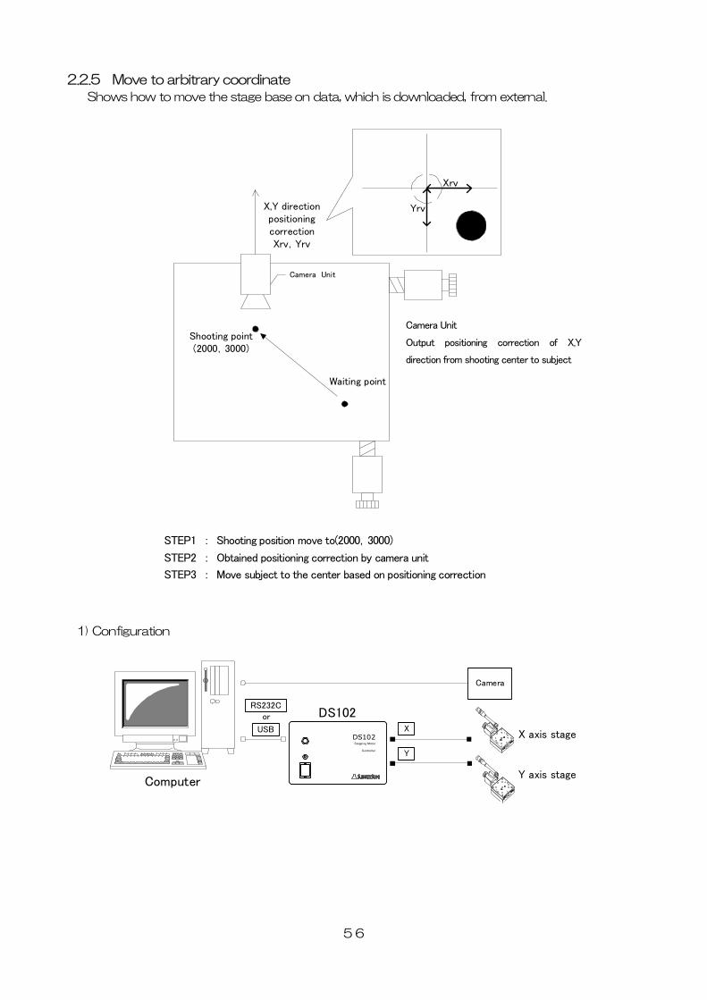
2.2.5 Move to arbitrary coordinate
Shows how to move the stage base on data, which is downloaded, from external.
56
1) Configuration
Waiting point
Shooting point(2000,3000)
Camera Unit
X,Y directionpositioningcorrectionXrv,Yrv
1
Xrv
Yrv
X axis stage
Y axis stage
DS102Stepping Motor
Controller
DS102
Computer
Camera
X
Y
USB
RS232Cor
STEP1 : Shooting position move to(2000,3000)
STEP2 : Obtained positioning correction by camera unit
STEP3 : Move subject to the center based on positioning correction
Camera Unit
Output positioning correction of X,Y
direction from shooting center to subject
2) Operation Outline
Program for stage is moved to arbitrary position to DS102 with the computer.
① Run the program from the computer.
3) Connection
Connect DS102
① Plug computer USB port into USB connector.
(In case of using RS232C, connect RS232C and computer)
② Connect X axis motor connector and X axis stage.
③ Connect Y axis motor connector and Y axis stage.
4) Programming
MSComm1.Output = “AXI1:SELSP 0:F0 1000” ’X stage set up speed
MSComm1.Output = “AXI2:SELSP 1:F1 1000” ’Y stage set up speed
MSComm1.Output = “AXI1:GOABS 2000” ’X stage move to shooting point
MSComm1.Output = “AXI2:GOABS 3000” ’Y stage move to shooting point
intXrv = Obtain X direction correction position ( )
intYrv = Obtain Y direction correction position ( )
MSComm1.Output = “AXI1:PULS intXrv:GO CW” ’X stage move to correction position
MSComm1.Output = “AXI2:PULS intYrv:GO CW” ’Y stage move to correction position
Program contents
① Set up operation speed of X stage, Y stage.
② Move X stage, Y stage to shooting point. <STEP1>
③ Get positioning correction from camera units. <STEP2>
④ Move X stage, Y stage to correction point. <STEP3>
57
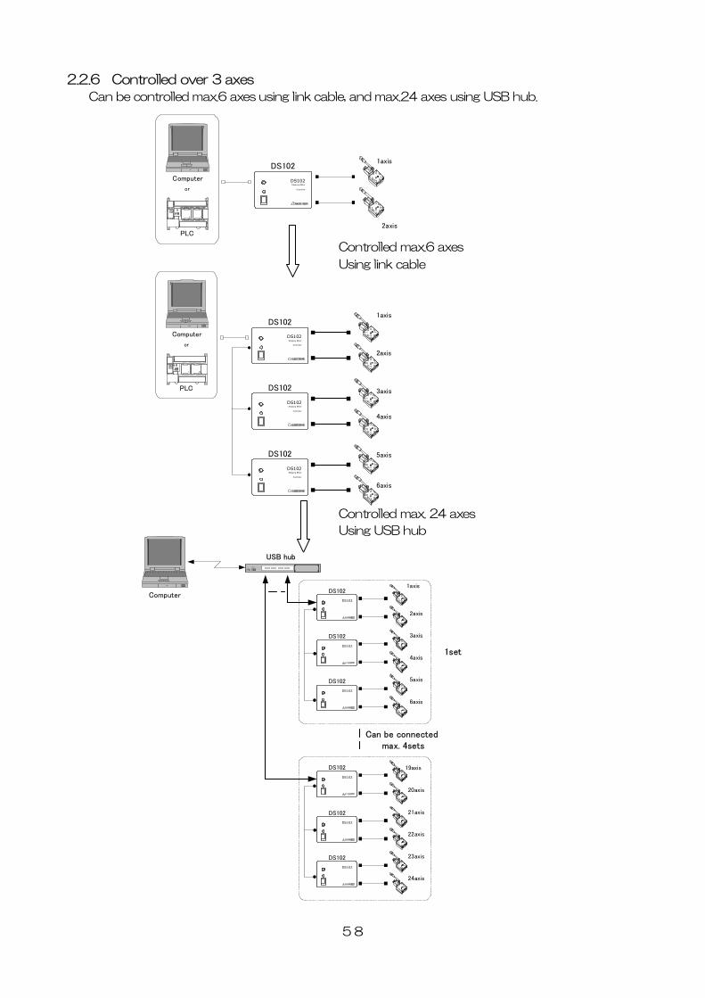
2.2.6 Controlled over 3 axes
Can be controlled max.6 axes using link cable, and max.24 axes using USB hub.
58
Controlled max. 24 axes
Using USB hub
Controlled ma
DS102Stepping Motor
Controller
DS1021axis
2axis
Computer
PLC
or
x.6 axes
Using link cable
A
C
USBハブ
Computer
1set
Can be connected max. 4sets
1axis
2axis
DS102
DS102
3axis
4axis
DS102
DS102
5axis
6axis
DS102
DS102
USB hub
19axis
20axis
DS102
DS102
21axis
22axis
DS102
DS102
23axis
24axis
DS102
DS102
DS102Stepping Motor
Controller
DS1021axis
2axis
DS102Stepping Motor
Controller
DS102 3axis
4axis
DS102Stepping Motor
Controller
DS102 5axis
6axis
Computer
PLC
or
59
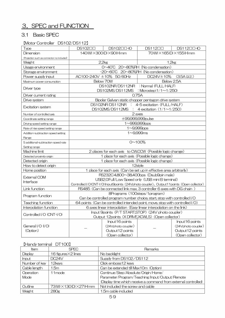
3.SPEC and FUNCTION
3.1 Basic SPEC
【Motor Controller DS102/DS112】
Type DS102□□ DS102□□-IO DS112□□ DS112□□-IO
Dimension
(Projection such as connector no included)
140(W)×300(D)×90(H)mm 70(W)×165(D)×155(H)mm
Weight 2.2kg 1.2kg
Usage environment 0~40℃ 20~80%RH(No condensation)
Storage environment -20~60℃ 20~80%RH(No condensation)
Power supply input AC100-240V ±10% 50/60Hz DC24V±10% (3.5A 以上)
Maximum power consumption Below 70W Below 2.5A
Driver type DS102NR/DS112NR :Normal (FULL/HALF)
DS102MS/DS112MS :Microstep(1/1~1/250)
Driver current rating 0.75A
Drive system Bipolar Galvan static chopper pentagon drive system
Excitation system DS102NR/DS112NR : 4-5 excitation(FULL/HALF)
DS102MS/DS112MS : 4 excitation(1/1~1/250)
Number of controlled axis 2 axes
Coordinate setting range ±99,999,999pulse
Driving speed setting range 1~999,999pps
Rate of rise speed setting range 1~9,999pps
Addition-subtraction speed setting
Range
1~9,999ms
S additional-subtraction speed rate
Setting range
0~100%
Machine limit 2 places for each axis to CW,CCW(Possible logic change)
Detected proximity origin 1 place for each axis(Possible logic change)
Detected origin 1 place for each axis(Possible logic change)
How to detect origin 12style
Home position 1 place for each axis(Can be set up in effective area arbitrarily)
External COM
Interface
RS232C:4,800~38,400bps(Dsub9pin male)
USB2.0:Full/Low Speed only(USB mini B terminal)
Controlled I/O(CNT-I/O):Input9points(24Vphoto coupler)、Output11points(Open collector)
Link function RS485(Can be connected link max. 3 controller 6 axes with DG chain )
Program function 8Programs(100steps/1program)
Can be controlled program number choice, start, stop with controlled I/O
Teaching function 64 points(Can be controlled intended point, move, stop with controlled I/O)
Interpolation function 6 axes linear interpolation(Easy linear interpolation on the link)
Controlled I/O (CNT-I/O) Input 9points(P/T START,STOP)(24V photo coupler)
Output 12points(X DRIVE,XCWLS)(Open collector)
General I/O (I/O)
(Option) -
Input16 points
(24Vphoto coupler)
Output12 points
(Open collector)
-
Input16 points
(24Vphoto coupler)
Output12 points
(Open collector)
【Handy terminal DT100】
Item SPEC Remarks
Display 16 figures×2 lines No backlight
Input DC24V Supply from DS102/DS112
Number of key 12keys Click emboss12 keys
Cable length 1.5m Can be extended till Max10m (Option)
Operation
Mode
11mode Continue/Step/Absolute/Origin/Home/
Parameter/Program/Teaching/Input/Output/Remote
(Display time which receive a command from external controlled)
Outline 73(W)×130(D)×27(H)mm Not included the screw and cable
Weight 280g 1.5m cable included
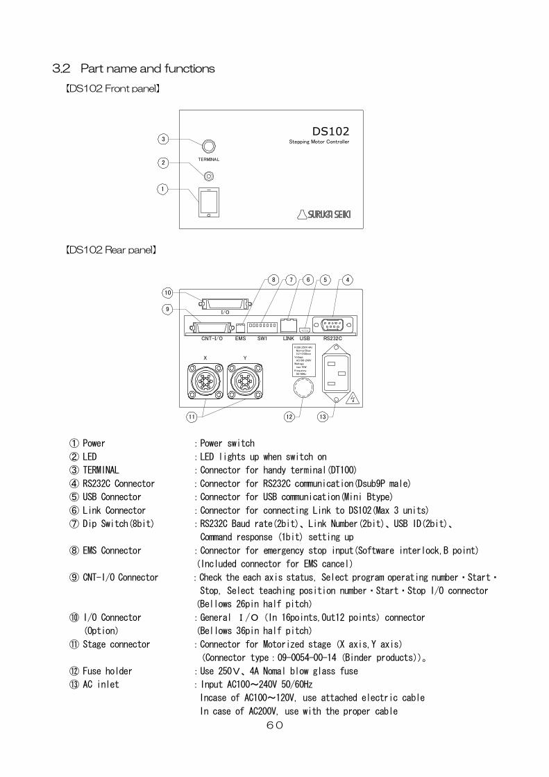
3.2 Part name and functions
【DS102 Front panel】
60
【DS102 Rear panel】
TERMINAL
DS102Stepping Motor Controller
1
2
3
X Y
I/O
FUSE(250V 4A) Normal Blow 5.2×20.0mmVoltage AC100-240VWattage max 70W
Frequency 50/60Hz
CNT-I/O EMS SW1 LINK USB RS232C
9
8 7 6 5 4
11 12 13
10
① Power :Power switch
② LED :LED lights up when switch on
③ TERMINAL :Connector for handy terminal(DT100)
④ RS232C Connector :Connector for RS232C communication(Dsub9P male)
⑤ USB Connector :Connector for USB communication(Mini Btype)
⑥ Link Connector :Connector for connecting Link to DS102(Max 3 units)
⑦ Dip Switch(8bit) :RS232C Baud rate(2bit)、Link Number(2bit)、USB ID(2bit)、
Command response (1bit) setting up
⑧ EMS Connector :Connector for emergency stop input(Software interlock,B point)
(Included connector for EMS cancel)
⑨ CNT-I/O Connector :Check the each axis status, Select program operating number・Start・
Stop, Select teaching position number・Start・Stop I/O connector
(Bellows 26pin half pitch)
⑩ I/O Connector :General I/O(In 16points,Out12 points)connector
(Option) (Bellows 36pin half pitch)
⑪ Stage connector :Connector for Motorized stage(X axis,Y axis)
(Connector type:09-0054-00-14(Binder products))。
⑫ Fuse holder :Use 250V、4A Nomal blow glass fuse
⑬ AC inlet :Input AC100~240V 50/60Hz
Incase of AC100~120V, use attached electric cable
In case of AC200V, use with the proper cable
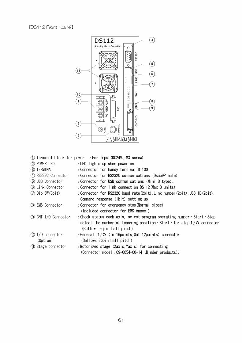
【DS112 Front panel】
61
① Terminal block for power :For input(DC24V、M3 screw)
DT100
Dsub9P male)
t),USB ID(2bit),
lose)
perating number・Start・Stop
⑩ I/O connector : 2points)connector
⑪ for connecting
)
XY
TER
MIN
AL
PO
WER
+24
V
CN
T-I/
OEM
SS
W1
LIN
KU
SB
RS
232C
DS112Stepping Motor Controller
GN
DFG
I/O
11
1
10
2
3
4
5
6
7
8
9
② POWER LED :LED lights up when power on
③ TERMINAL :Connector for handy terminal
④ RS232C Connector :Connector for RS232C communications(
⑤ USB Connector :Connector for USB communications(Mini B type)。
⑥ Link Connector :Connector for link connection DS112(Max 3 units)
⑦ Dip SW(8bit) :Connector for RS232C baud rate(2bit),Link number(2bi
Command response (1bit) setting up
⑧ EMS Connector :Connector for emergency stop(Normal c
(Included connector for EMS cancel)
⑨ CNT-I/O Connector :Check status each axis, select program o
select the number of teaching position・Start・for stopI/O connector
(Bellows 26pin half pitch)
General I/O(In 16points,Out 1
(Option) (Bellows 36pin half pitch)
Stage connector :Motorized stage(Xaxis,Yaxis)
(Connector model:09-0054-00-14(Binder products)
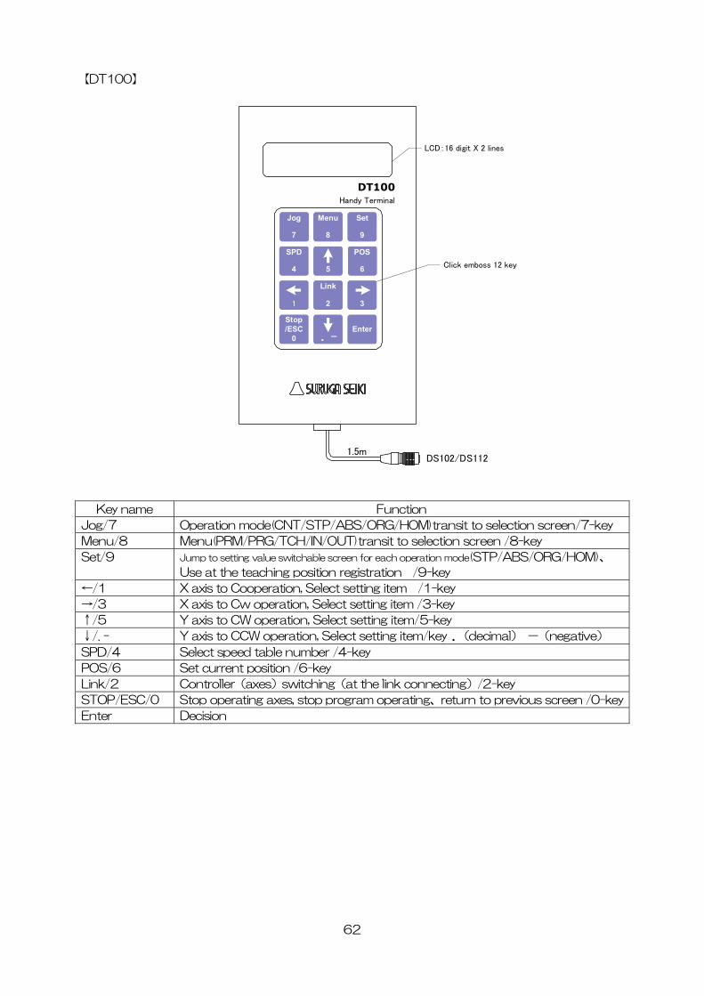
【DT100】
62
Key name Function
DT100Handy Terminal
Stop/ESC
0Enter
. -
Jog
7
Menu
8
Set
9
SPD
4
POS
6
Link
2 31
5
DS102/DS1121.5m
LCD:16 digit X 2 lines
Click emboss 12 key
Jo Operation mode(CNT/STP/ABS/O ransit to selection screen/7-key g/7 RG/HOM)t
Menu/8 Menu(PRM/PRG/TCH/IN/OUT)transit to selection screen /8-key
Set/9 Jump to setting value switchable screen for each operation mode(STP/ABS/ORG/HOM)、
Use at the teaching position registration /9-key
←/1 X axis to Cooperation, Select setting item /1-key
→/3 X axis to Cw operation, Select setting item /3-key
↑/5 Y axis to CW operation, Select setting item/5-key
↓/. - Y axis to CCW operation, Select setting item/key .(decimal) -(negative)
SPD/4 Select speed table number /4-key
POS/6 Set current position /6-key
Link/2 Controller(axes)switching(at the link connecting)/2-key
STOP/ESC/0 ous screen /0-keyStop operating axes, stop program operating、return to previ
Enter Decision
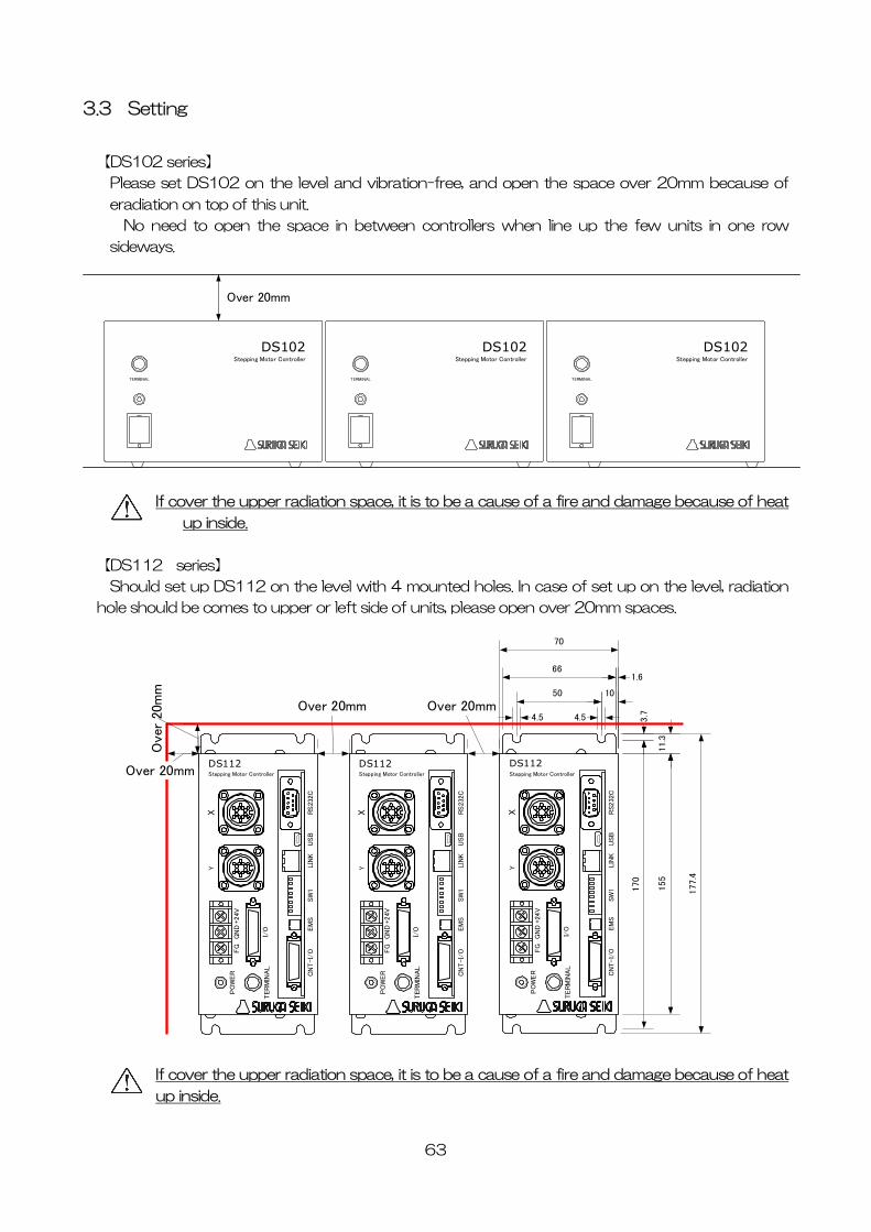
3.3 Setting
【DS102 series】
Please set DS102 on the level and vibration-free, and open the space over 20mm because of
eradiation on top of this unit.
No need to open the space in between controllers when line up the few units in one row
sideways.
TERMINAL
DS102Stepping Motor Controller
TERMINAL
DS102Stepping Motor Controller
TERMINAL
DS102Stepping Motor Controller
Over 20mm
If cover the upper radiation space, it is to be a cause of a fire and damage because of heat
up inside.
【DS112 series】
Should set up DS112 on the level with 4 mounted holes. In case of set up on the level, radiation
hole should be comes to upper or left side of units, please open over 20mm spaces.
155
70
XY
TERM
INA
L
PO
WER
+24V
CN
T-I/
OEM
SSW
1LIN
KU
SB
RS232
C
DS112Stepping Motor Controller
GN
DFG
I/O
177.4
11.3
1.6
3.7
170
10
4.5 4.5
50
66
XY
TER
MIN
AL
PO
WER
+24V
CN
T-I
/OEM
SSW
1LIN
KU
SB
RS
232C
DS112Stepping Motor Controller
GN
DFG
I/O
Over 20mm
XY
TER
MIN
AL
PO
WER
+24V
CN
T-I
/OEM
SSW
1LIN
KU
SB
RS
232C
DS112Stepping Motor Controller
GN
DFG
I/O
Over 20mm
Ove
r 20
mm
Over 20mm
If cover the upper radiation space, it is to be a cause of a fire and damage because of heat
up inside.
63
3.4 External Interface
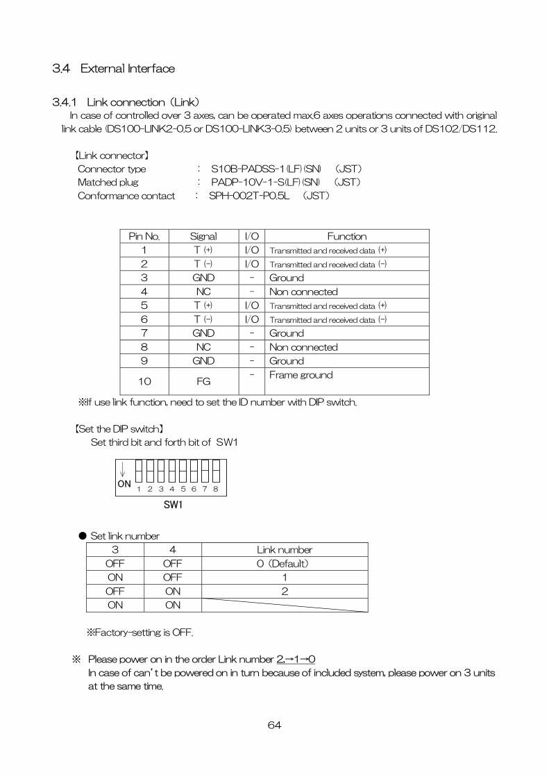
3.4.1 Link connection(Link)
In case of controlled over 3 axes, can be operated max.6 axes operations connected with original
link cable (DS100-LINK2-0.5 or DS100-LINK3-0.5) between 2 units or 3 units of DS102/DS112.
【Link connector】
Connector type : S10B-PADSS-1(LF)(SN) (JST)
Matched plug : PADP-10V-1-S(LF)(SN) (JST)
Conformance contact : SPH-002T-P0.5L (JST)
Pin No. Signal I/O Function
1 T (+) I/O Transmitted and received data (+)
2 T (-) I/O Transmitted and received data (-)
3 GND - Ground
4 NC - Non connected
5 T (+) I/O Transmitted and received data (+)
6 T (-) I/O Transmitted and received data (-)
7 GND - Ground
8 NC - Non connected
9 GND - Ground
10 FG - Frame ground
※If use link function, need to set the ID number with DIP switch.
【Set the DIP switch】
Set third bit and forth bit of SW1
1 2 3 4 5 6 ON
7 8
SW1
● Set link number
3 4 Link number
OFF OFF 0(Default)
ON OFF 1
OFF ON 2
ON ON
※Factory-setting is OFF.
※ Please power on in the order Link number 2,→1→0
In case of can’t be powered on in turn because of included system, please power on 3 units
at the same time.
64
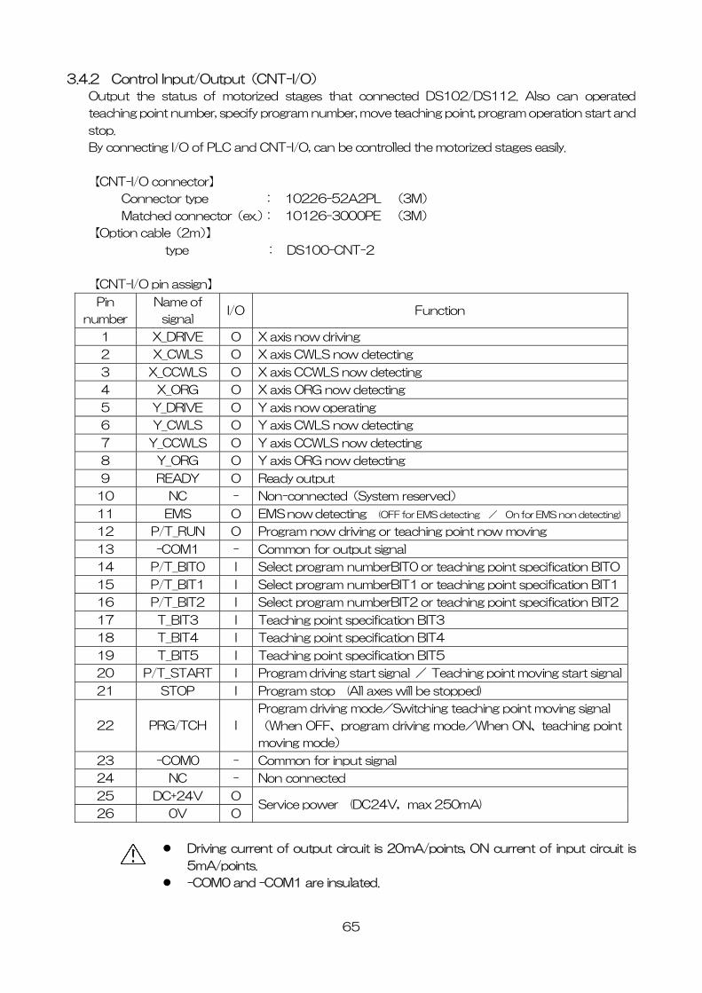
3.4.2 Control Input/Output(CNT-I/O)
Output the status of motorized stages that connected DS102/DS112. Also can operated
teaching point number, specify program number, move teaching point, program operation start and
stop.
By connecting I/O of PLC and CNT-I/O, can be controlled the motorized stages easily.
【CNT-I/O connector】
Connector type : 10226-52A2PL (3M)
Matched connector(ex.): 10126-3000PE (3M)
【Option cable(2m)】
type : DS100-CNT-2
【CNT-I/O pin assign】
Pin
number
Name of
signal I/O Function
1 X_DRIVE O X axis now driving
2 X_CWLS O X axis CWLS now detecting
3 X_CCWLS O X axis CCWLS now detecting
4 X_ORG O X axis ORG now detecting
5 Y_DRIVE O Y axis now operating
6 Y_CWLS O Y axis CWLS now detecting
7 Y_CCWLS O Y axis CCWLS now detecting
8 Y_ORG O Y axis ORG now detecting
9 READY O Ready output
10 NC - Non-connected(System reserved)
11 EMS O EMS now detecting (OFF for EMS detecting / On for EMS non detecting)
12 P/T_RUN O Program now driving or teaching point now moving
13 -COM1 - Common for output signal
14 P/T_BIT0 I Select program numberBIT0 or teaching point specification BITO
15 P/T_BIT1 I Select program numberBIT1 or teaching point specification BIT1
16 P/T_BIT2 I Select program numberBIT2 or teaching point specification BIT2
17 T_BIT3 I Teaching point specification BIT3
18 T_BIT4 I Teaching point specification BIT4
19 T_BIT5 I Teaching point specification BIT5
20 P/T_START I Program driving start signal / Teaching point moving start signal
21 STOP I Program stop (All axes will be stopped)
22 PRG/TCH I
Program driving mode/Switching teaching point moving signal
(When OFF、program driving mode/When ON、teaching point
moving mode)
23 -COM0 - Common for input signal
24 NC - Non connected
25 DC+24V O
26 0V O Service power (DC24V,max 250mA)
Driving current of output circuit is 20mA/points, ON current of input circuit is
5mA/points.
-COM0 and -COM1 are insulated.
65
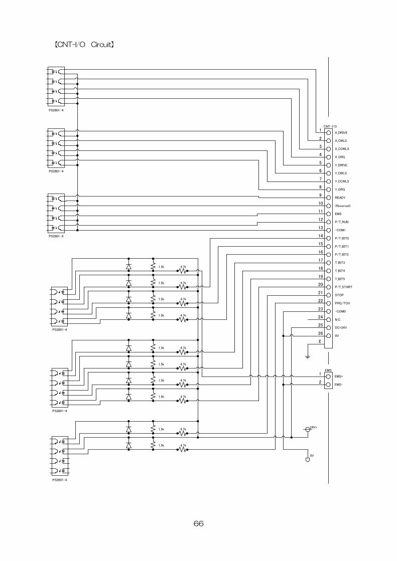
【CNT-I/O Circuit】
1
2
3
4
5
6
7
8
9
10
11
12
13
14
15
16
17
18
19
20
21
22
23
24
25
26
CNT-I/O
X_DRIVE
Y_CCWLS
T_BIT3
P/T_BIT2
P/T_BIT1
P/T_BIT0
EMS
(Reserved)
READY
Y_ORG
Y_CWLS
Y_DRIVE
X_ORG
X_CCWLS
X_CWLS
T_BIT4
PRG/TCH
DC+24V
N.C.
-COM0
STOP
P/T_START
-COM1
P/T_RUN
T_BIT5
0V
EMS
EMS-
EMS+1
2
E
24V+
0V
PS2801-4
PS2801-4
PS2801-4
PS2801-4
PS2801-4
PS2801-4
4.7k
4.7k
4.7k
4.7k
1.5k
1.5k
1.5k
1.5k
1.5k
1.5k
1.5k
1.5k
1.5k
1.5k
4.7k
4.7k
4.7k
4.7k
4.7k
4.7k
66
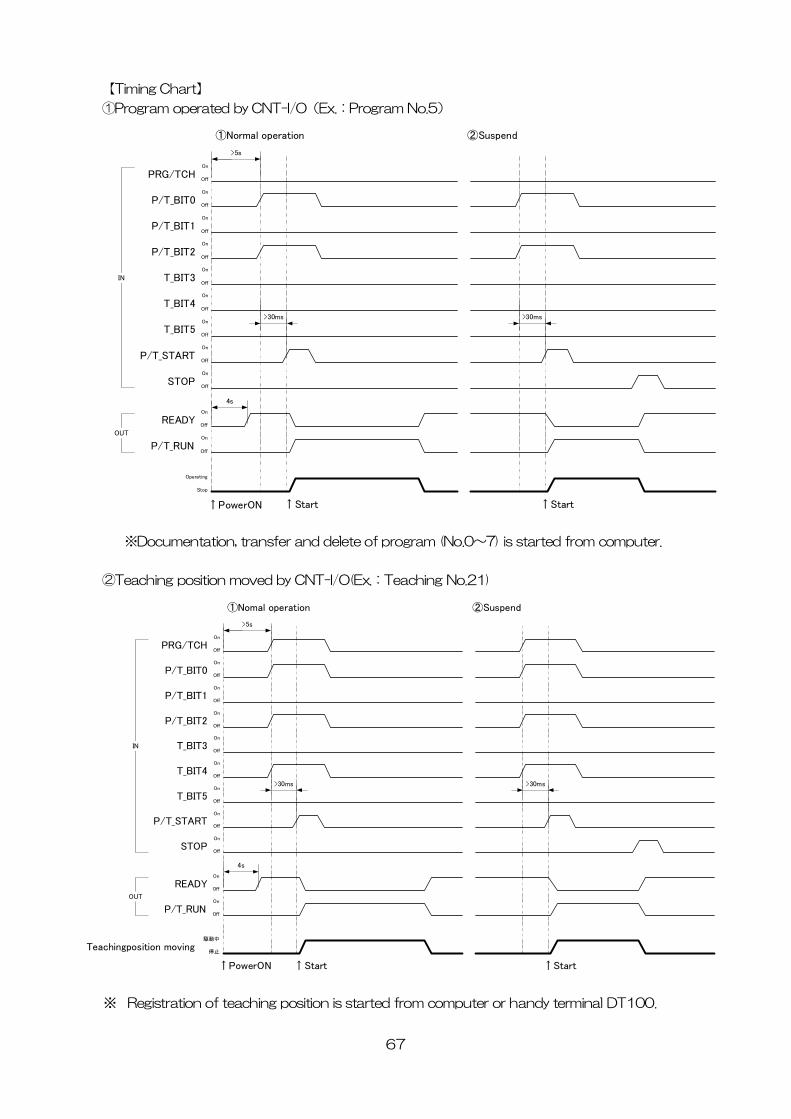
【Timing Chart】
①Program operated by CNT-I/O(Ex.:Program No.5)
PRG/TCH
P/T_START
P/T_RUN
P/T_BIT0
P/T_BIT1
P/T_BIT2
READY
T_BIT3
T_BIT4
T_BIT5
↑Start
On
Off
On
Off
On
Off
On
Off
On
Off
On
Off
On
Off
On
Off
On
Off
On
Off
Operating
Stop
↑PowerON
>5s
4s
>30ms
IN
OUT
STOPOn
Off
>30ms
↑Start
①Normal operation ②Suspend
※Documentation, transfer and delete of program (No.0~7) is started from computer.
②Teaching position moved by CNT-I/O(Ex.:Teaching No.21)
PRG/TCH
P/T_START
P/T_RUN
P/T_BIT0
P/T_BIT1
P/T_BIT2
READY
T_BIT3
T_BIT4
T_BIT5
Teachingposition moving
↑Start
On
Off
On
Off
On
Off
On
Off
On
Off
On
Off
On
Off
On
Off
On
Off
On
Off
駆動中
停止
↑PowerON
>5s
4s
>30ms
IN
OUT
STOPOn
Off
>30ms
↑Start
①Nomal operation ②Suspend
※ Registration of teaching position is started from computer or handy terminal DT100.
67
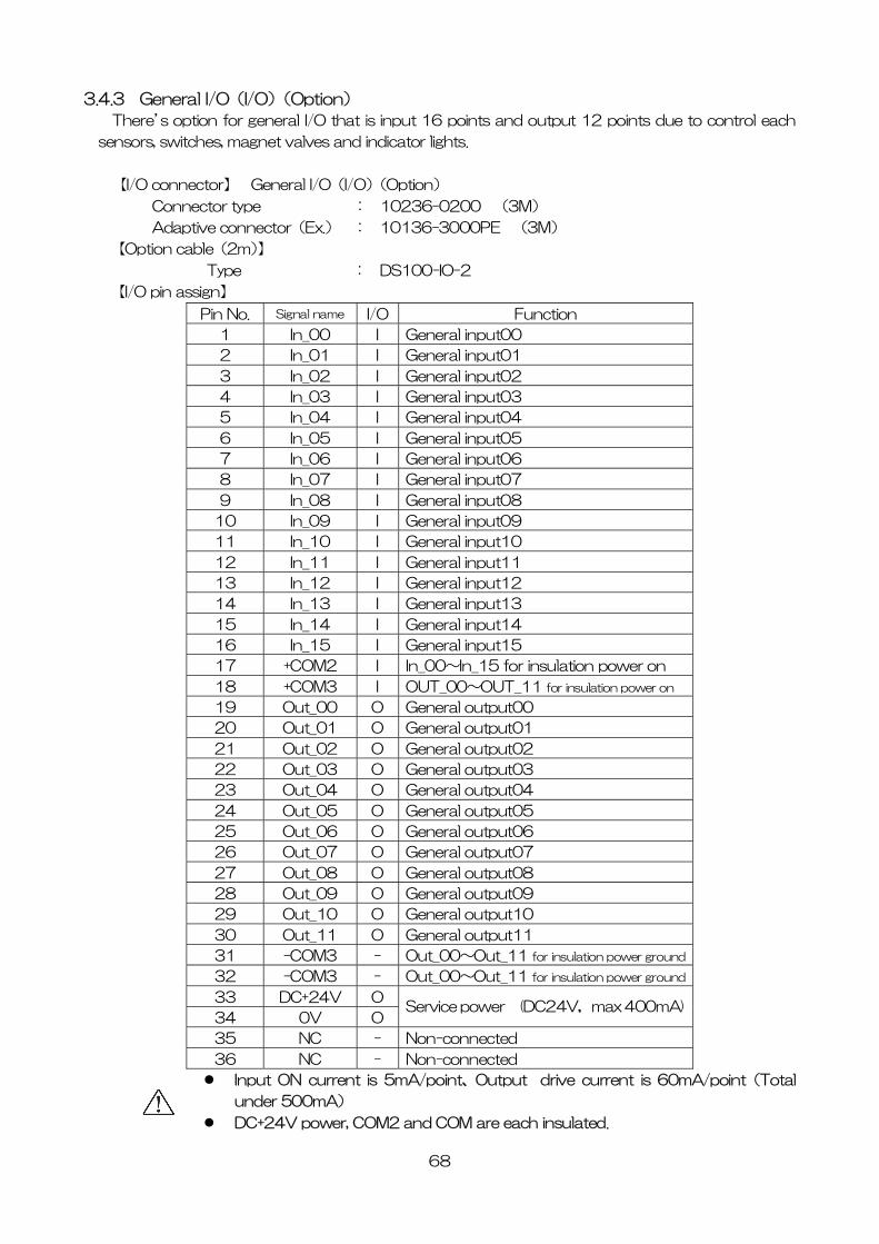
3.4.3 General I/O(I/O)(Option)
There’s option for general I/O that is input 16 points and output 12 points due to control each
sensors, switches, magnet valves and indicator lights.
【I/O connector】 General I/O(I/O)(Option)
Connector type : 10236-0200 (3M)
Adaptive connector(Ex.) : 10136-3000PE (3M)
【Option cable(2m)】
Type : DS100-IO-2
【I/O pin assign】
Pin No. I/OSignal name Function
1 In_00 I General input00
2 In_01 I General input01
3 In_02 I General input02
4 In_03 I General input03
5 In_04 I General input04
6 In_05 I General input05
7 In_06 I General input06
8 In_07 I General input07
9 In_08 I General input08
10 In_09 I General input09
11 In_10 I General input10
12 In_11 I General input11
13 In_12 I General input12
14 In_13 I General input13
15 In_14 I General input14
16 In_15 I General input15
17 +COM2 I In_00~In_15 for insulation power on
18 +COM3 I OUT_00~OUT_11 for insulation power on
19 Out_00 O General output00
20 Out_01 O General output01
21 Out_02 O General output02
22 Out_03 O General output03
23 Out_04 O General output04
24 Out_05 O General output05
25 Out_06 O General output06
26 Out_07 O General output07
27 Out_08 O General output08
28 Out_09 O General output09
29 Out_10 O General output10
30 Out_11 O General output11
31 -COM3 - Out_00~Out_11 for insulation power ground
32 -COM3 - Out_00~Out_11 for insulation power ground
33 DC+24V O
34 0V O Service power (DC24V,max 400mA)
35 NC - Non-connected
36 NC - Non-connected
Input ON current is 5mA/point、Output drive current is 60mA/point(Total
under 500mA)
DC+24V power, COM2 and COM are each insulated.
68
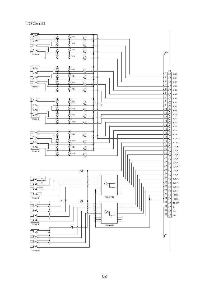
【I/O Circuit】
69
1
2
3
4
5
6
7
8
9
10
11
12
13
14
15
16
17
18
19
20
21
22
23
24
25
26
I/O
IN_00
IN_06
+COM2
IN_15
IN_14
IN_13
IN_10
IN_09
IN_08
IN_07
IN_05
IN_04
IN_03
IN_02
IN_01
+COM3
OUT_03
OUT_06
OUT_05
OUT_04
OUT_02
OUT_01
IN_12
IN_11
OUT_00
OUT_07
24V+
0V
TLP281-4
TLP281-4
TLP281-4
TLP281-4
TLP281-4
TLP281-4
4.7k
4.7k
4.7k
4.7k
1.5k
1.5k
1.5k
1.5k
1.5k
1.5k
1.5k
1.5k
1.5k
1.5k
4.7k
4.7k
4.7k
4.7k
4.7k
4.7k
27
28
29
30
31
32
33
34
35
36
OUT_10
OUT_09
OUT_08
OUT_11
0V
N.C.
DC+24V
-COM3
-COM3
N.C.
TLP281-4
1.5k
1.5k
4.7k
4.7k
1.5k
1.5k
4.7k
4.7k
1.5k
1.5k
4.7k
4.7k
TD62084AFG
TD62084AFG
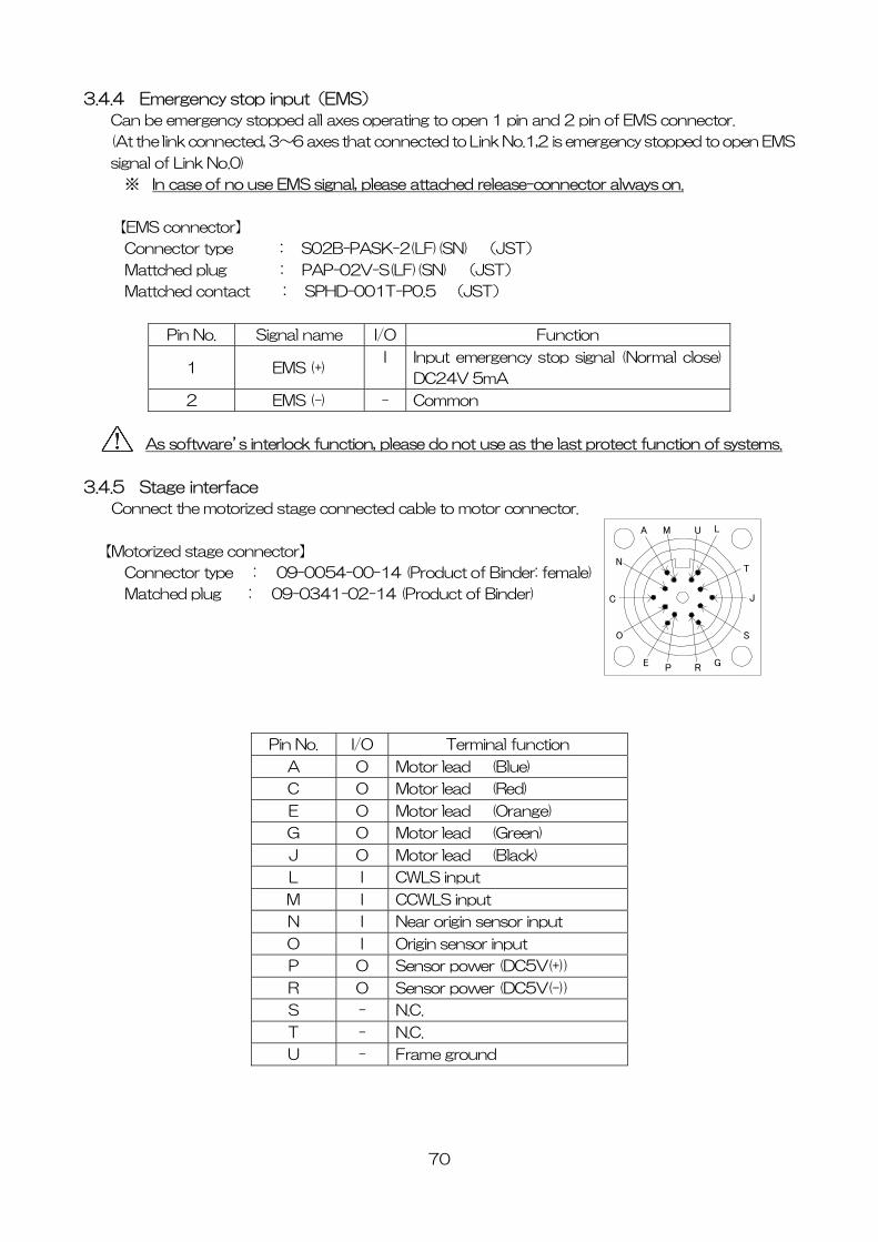
3.4.4 Emergency stop input(EMS)
Can be emergency stopped all axes operating to open 1 pin and 2 pin of EMS connector.
(At the link connected, 3~6 axes that connected to Link No.1,2 is emergency stopped to open EMS
signal of Link No.0)
※ In case of no use EMS signal, please attached release-connector always on.
【EMS connector】
Connector type : S02B-PASK-2(LF)(SN) (JST)
Mattched plug : PAP-02V-S(LF)(SN) (JST)
Mattched contact : SPHD-001T-P0.5 (JST)
Pin No. Signal name I/O Function
1 EMS (+) I Input emergency stop signal (Normal close)
DC24V 5mA
2 EMS (-) - Common
As software’s interlock function, please do not use as the last protect function of systems.
3.4.5 Stage interface
Connect the motorized stage connected cable to motor connector.
A
P
O
N
M L
R
J
T
S
GE
C
U
【Motorized stage connector】
Connector type : 09-0054-00-14 (Product of Binder: female)
Matched plug : 09-0341-02-14 (Product of Binder)
Pin No. I/O Terminal function
A O Motor lead (Blue)
C O Motor lead (Red)
E O Motor lead (Orange)
G O Motor lead (Green)
J O Motor lead (Black)
L I CWLS input
M I CCWLS input
N I Near origin sensor input
O I Origin sensor input
P O Sensor power (DC5V(+))
R O Sensor power (DC5V(-))
S - N.C.
T - N.C.
U - Frame ground
70
3.5 Driver division number setting
Different how to set the division number normal type and micro-step type.
Driver type Division number setting
Normal driver Can be switched FULL/Half from handy terminal(DT100),control
software (DSCONTROL-WIN), communication command.
Micro step driver Need to open the cover and set the rotary switch of micro-step driver.
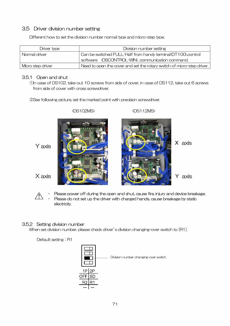
3.5.1 Open and shut
①In case of DS102, take out 10 screws from side of cover, in case of DS112, take out 6 screws
from side of cover with cross screwdriver.
②See following picture, set the marked point with precision screwdriver.
<DS102MS> <DS112MS>
Y axis
X axis
・ Please power off during the open and shut, cause fire, injury and
・ Please do not set up the driver with charged hands, cause brea
electricity.
3.5.2 Setting division number When set division number, please check driver’s division changing-over switch
Default setting:R1
Division number changin itch over swg-
71
X axis
Y axis
device breakage.
kage by static
to [R1].
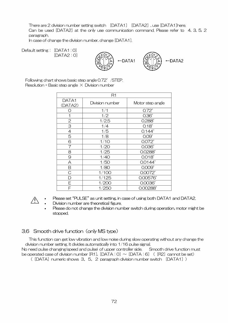
There are 2 division number setting switch [DATA1][DATA2], use [DATA1]here.
Can be used [DATA2] at the only use communication command. Please refer to 4, 3, 5, 2
paragraph.
In case of change the division number, change [DATA1].
Default setting: [DATA1 : 0]
[DATA2:0]
Following chart shows basic step angle 0.72°/STEP.
Resolution = Basic step angle × Division number
R1
DATA1
(DATA2) Division number Motor step angle
0 1/1 0.72°
1 1/2 0.36°
2 1/2.5 0.288°
3 1/4 0.18°
4 1/5 0.144°
5 1/8 0.09°
6 1/10 0.072°
7 1/20 0.036°
8 1/25 0.0288°
9 1/40 0.018°
A 1/50 0.0144°
B 1/80 0.009°
C 1/100 0.0072°
D 1/125 0.00576°
E 1/200 0.0036°
F 1/250 0.00288°
• Please set “PULSE” as unit setting, in case of using both DATA1 and DATA2.
• Division number are theoretical figure.
• Please do not change the division number switch during operation, motor might be
stopped.
3.6 Smooth drive function(only MS type)
This function can get low vibration and low noise during slow operating without any change the
division number setting. It divides automatically into 1/16 pulse signal.
No need pulse changing(speed and pulse) of upper controller side. Smooth drive function must
be operated case of division number [R1],[DATA:0]~[DATA:6]([R2]cannot be set)
([DATA]numeric shows 3.5.2 paragraph division number switch [DATA1])
72
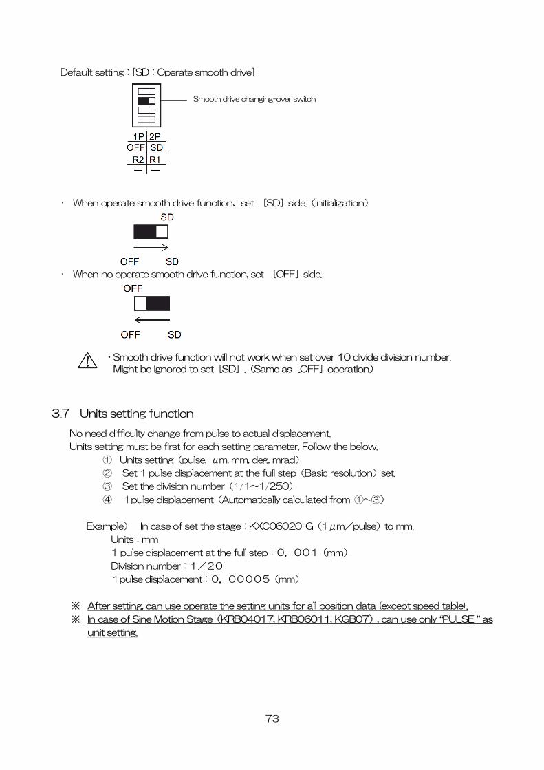
Default setting:[SD:Operate smooth drive]
Smooth drive changing-over switch
• When operate smooth drive function、set [SD]side.(Initialization)
• When no operate smooth drive function, set [OFF]side.
・Smooth drive function will not work when set over 10 divide division number.
Might be ignored to set[SD].(Same as[OFF]operation)
3.7 Units setting function
No need difficulty change from pulse to actual displacement.
Units setting must be first for each setting parameter. Follow the below.
① Units setting(pulse, μm, mm, deg, mrad)
② Set 1 pulse displacement at the full step(Basic resolution)set.
③ Set the division number(1/1~1/250)
④ 1pulse displacement(Automatically calculated from ①~③)
Example) In case of set the stage:KXC06020-G(1μm/pulse)to mm.
Units:mm
1 pulse displacement at the full step:0.001(mm)
Division number:1/20
1pulse displacement:0.00005(mm)
※ After setting, can use operate the setting units for all position data (except speed table).
※ In case of Sine Motion Stage(KRB04017, KRB06011, KGB07), can use only “PULSE ” as
unit setting.
73
3.8 Speed setting(Speed table)
This equipment memorized 10 speed table from 0 to 9. Each 2 axes(Max6 axes at Link) speed
is selected from speed table 0 to 9.
How to set the speed as shown bellows.:
① Select speed table from 0 to 9 as needed.
② Fix the speed table and change the setting level.
Example)
X axis・・・Speed table No.0 Fixed
Y axis・・・Speed table No.1 Fixed
Z axis・・・Speed table No.2 Fixed
U axis・・・Speed table No.3 Fixed
V axis・・・Speed table No.4 Fixed
W axis・・・Speed table No.5 Fixed
Set as above, and change the each speed table 0 to 5 setting level (L,F,R,S).
※ Control software (DSCONTROL-WIN) speed is set by ②
※ Can change speed in operation.
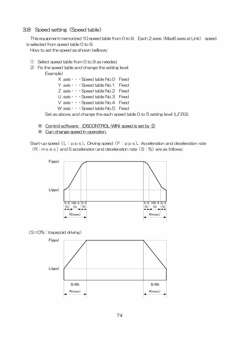
Start-up speed(L:pps)、Driving speed(F:pps)、Acceleration and deceleration rate
(R:msec)and S acceleration and deceleration rate(S:%)are as follows.:
(S=0%:trapezoid driving)
F(pps)
L(pps)
R(msec) R(msec)
S/2(%)
S/2(%)
S/2(%)
S/2(%)
100-S(%)
100-S(%)
F(pps)
L(pps)
R(msec) R(msec)
S=0% S=0%
74
75
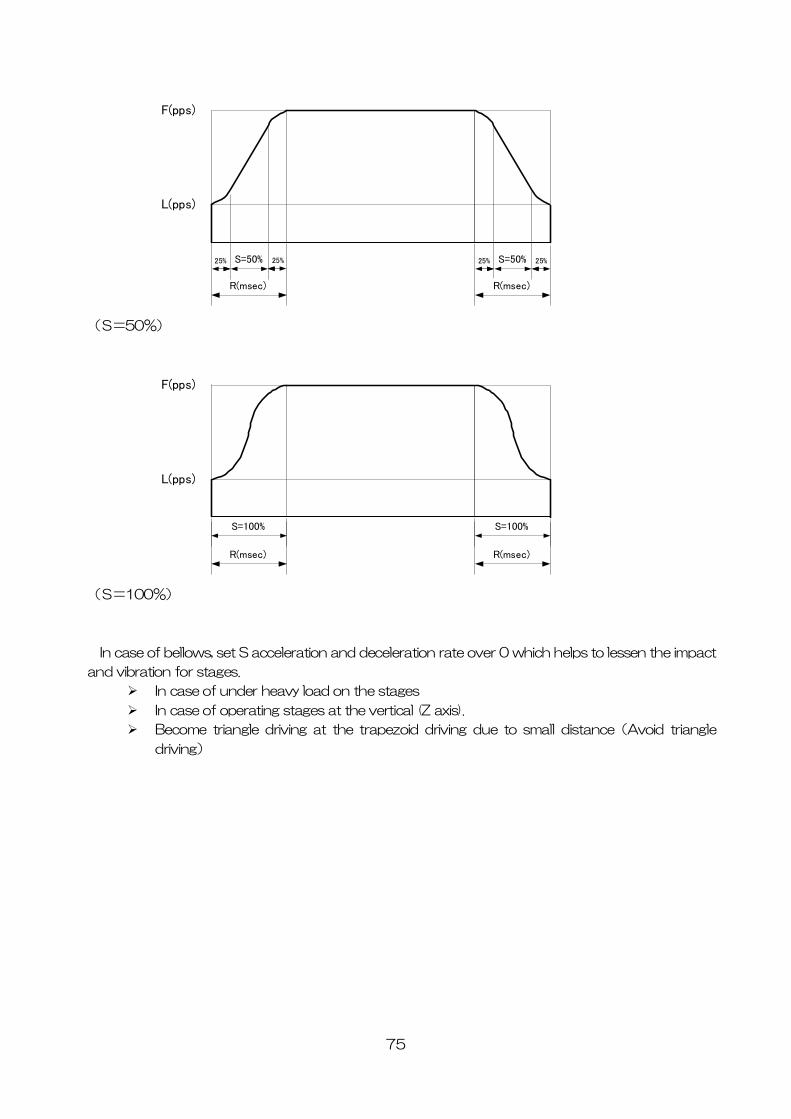
(S=50
(S=100%
In case of bellows, set S acceleration and deceleration rate over 0 which helps to lessen the impact
an
r heavy load on the stages
axis).
due to small distance(Avoid triangle
%)
F(pps)
L(pps)
R(msec)
S=50% S=50%
R(msec)
25% 25% 25% 25%
F(pps)
L(pps)
R(msec)
S=100% S=100%
R(msec)
)
d vibration for stages.
In case of unde
In case of operating stages at the vertical (Z
Become triangle driving at the trapezoid driving
driving)
76
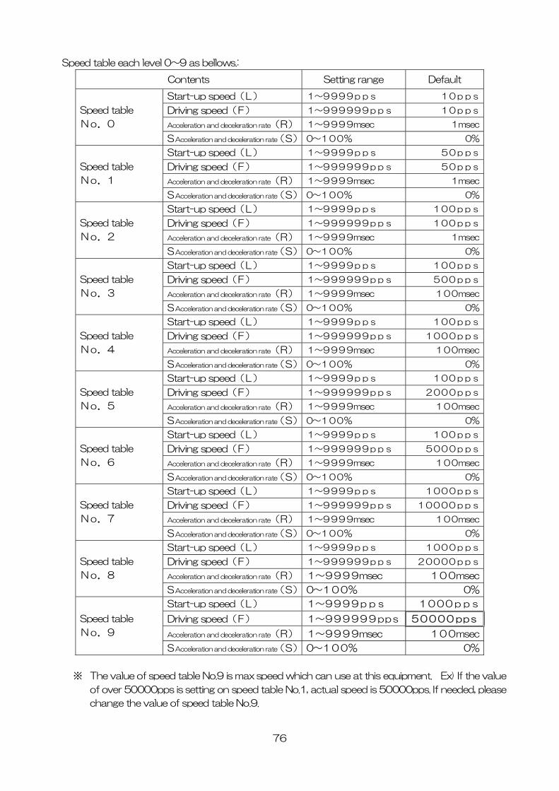
Speed table each level 0~9 as bellows.:
Contents Setting range Default
Start-up speed(L) 1~9999pps 10pps
Driving speed(F) 1~999999pps 10pps
Acceleration and deceleration rate(R) 1~9999msec 1msec
Speed table
No.0
S Acceleration and deceleration rate(S) 0~100% 0%
Start-up speed(L) 1~9999pps 50pps
Driving speed(F) 1~999999pps 50pps
Acceleration and deceleration rate(R) 1~9999msec 1msec
Speed table
No.1
S Acceleration and deceleration rate(S) 0~100% 0%
Start-up speed(L) 1~9999pps 100pps
Driving speed(F) 1~999999pps 100pps
Acceleration and deceleration rate(R) 1~9999msec 1msec
Speed table
No.2
S Acceleration and deceleration rate(S) 0~100% 0%
Start-up speed(L) 1~9999pps 100pps
Driving speed(F) 1~999999pps 500pps
Acceleration and deceleration rate(R) 1~9999msec 100msec
Speed table
No.3
S Acceleration and deceleration rate(S) 0~100% 0%
Start-up speed(L) 1~9999pps 100pps
Driving speed(F) 1~999999pps 1000pps
Acceleration and deceleration rate(R) 1~9999msec 100msec
Speed table
No.4
S Acceleration and deceleration rate(S) 0~100% 0%
Start-up speed(L) 1~9999pps 100pps
Driving speed(F) 1~999999pps 2000pps
Acceleration and deceleration rate(R) 1~9999msec 100msec
Speed table
No.5
S Acceleration and deceleration rate(S) 0~100% 0%
Start-up speed(L) 1~9999pps 100pps
Driving speed(F) 1~999999pps 5000pps
Acceleration and deceleration rate(R) 1~9999msec 100msec
Speed table
No.6
S Acceleration and deceleration rate(S) 0~100% 0%
Start-up speed(L) 1~9999pps 1000pps
Driving speed(F) 1~999999pps 10000pps
Acceleration and deceleration rate(R) 1~9999msec 100msec
Speed table
No.7
S Acceleration and deceleration rate(S) 0~100% 0%
Start-up speed(L) 1~9999pps 1000pps
Driving speed(F) 1~999999pps 20000pps
Acceleration and deceleration rate(R) 1~9999msec 100msec
Speed table
No.8
S Acceleration and deceleration rate(S) 0~100% 0%
Start-up speed(L) 1~9999pps 1000pps
Driving speed(F) 1~999999pps 50000pps
Acceleration and deceleration rate(R) 1~9999msec 100msec
Speed table
No.9
S Acceleration and deceleration rate(S) 0~100% 0%
※ The value of speed table No.9 is max speed which can use at this equipment. Ex) If the value
of over 50000pps is setting on speed table No.1, actual speed is 50000pps. If needed, please
change the value of speed table No.9.
77
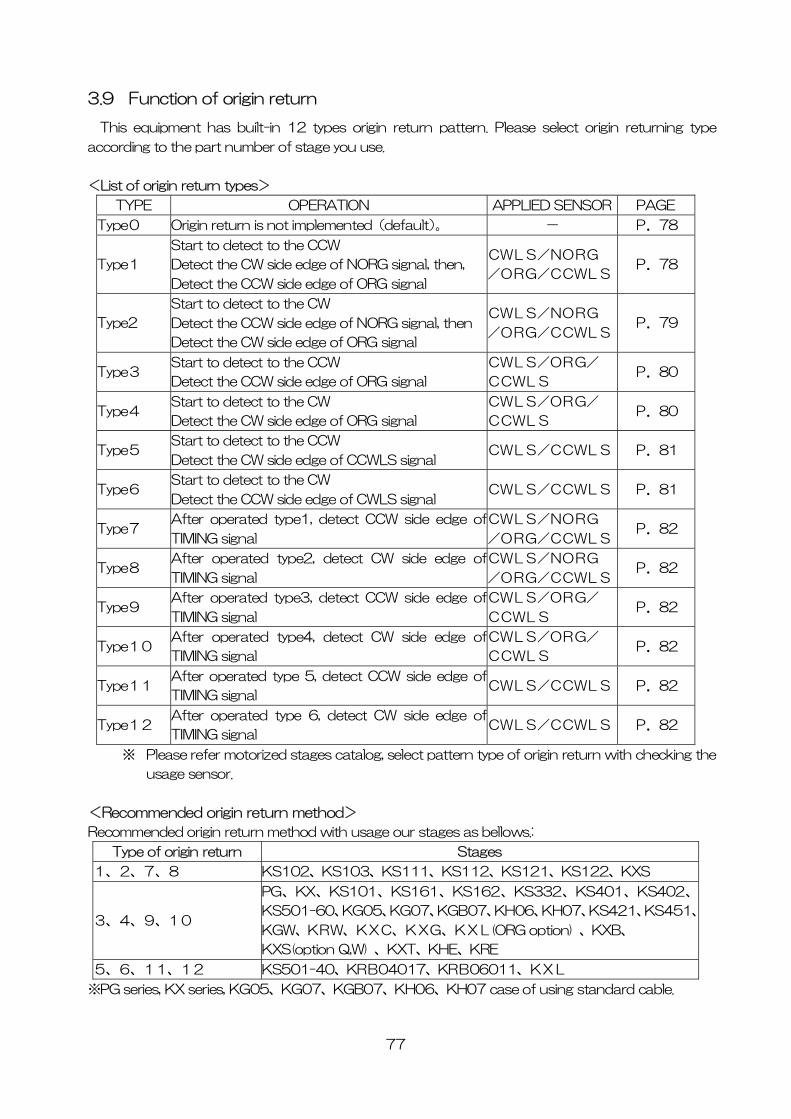
3.9 Function of origin return
This equipment has built-in 12 types origin return pattern. Please select origin returning type
according to the part number of stage you use.
<List of origin return types>
TYPE OPERATION APPLIED SENSOR PAGE
Type0 Origin return is not implemented(default)。 - P.78
Type1
Start to detect to the CCW
Detect the CW side edge of NORG signal, then,
Detect the CCW side edge of ORG signal
CWLS/NORG
/ORG/CCWLS P.78
Type2
Start to detect to the CW
Detect the CCW side edge of NORG signal, then
Detect the CW side edge of ORG signal
CWLS/NORG
/ORG/CCWLS P.79
Type3 Start to detect to the CCW
Detect the CCW side edge of ORG signal
CWLS/ORG/
CCWLS P.80
Type4 Start to detect to the CW
Detect the CW side edge of ORG signal
CWLS/ORG/
CCWLS P.80
Type5 Start to detect to the CCW
Detect the CW side edge of CCWLS signal CWLS/CCWLS P.81
Type6 Start to detect to the CW
Detect the CCW side edge of CWLS signal CWLS/CCWLS P.81
Type7 After operated type1, detect CCW side edge of
TIMING signal
CWLS/NORG
/ORG/CCWLS P.82
Type8 After operated type2, detect CW side edge of
TIMING signal
CWLS/NORG
/ORG/CCWLS P.82
Type9 After operated type3, detect CCW side edge of
TIMING signal
CWLS/ORG/
CCWLS P.82
Type10 After operated type4, detect CW side edge of
TIMING signal
CWLS/ORG/
CCWLS P.82
Type11 After operated type 5, detect CCW side edge of
TIMING signal CWLS/CCWLS P.82
Type12 After operated type 6, detect CW side edge of
TIMING signal CWLS/CCWLS P.82
※ Please refer motorized stages catalog, select pattern type of origin return with checking the
usage sensor.
<Recommended origin return method>
Recommended origin return method with usage our stages as bellows.:
Type of origin return Stages
1、2、7、8 KS102、KS103、KS111、KS112、KS121、KS122、KXS
3、4、9、10
PG、KX、KS101、KS161、KS162、KS332、KS401、KS402、
KS501-60、KG05、KG07、KGB07、KH06、KH07、KS421、KS451、
KGW、KRW、KXC、KXG、KXL(ORG option) 、KXB、
KXS(option Q,W) 、KXT、KHE、KRE
5、6、11、12 KS501-40、KRB04017、KRB06011、KXL
※PG series, KX series, KG05、KG07、KGB07、KH06、KH07 case of using standard cable.
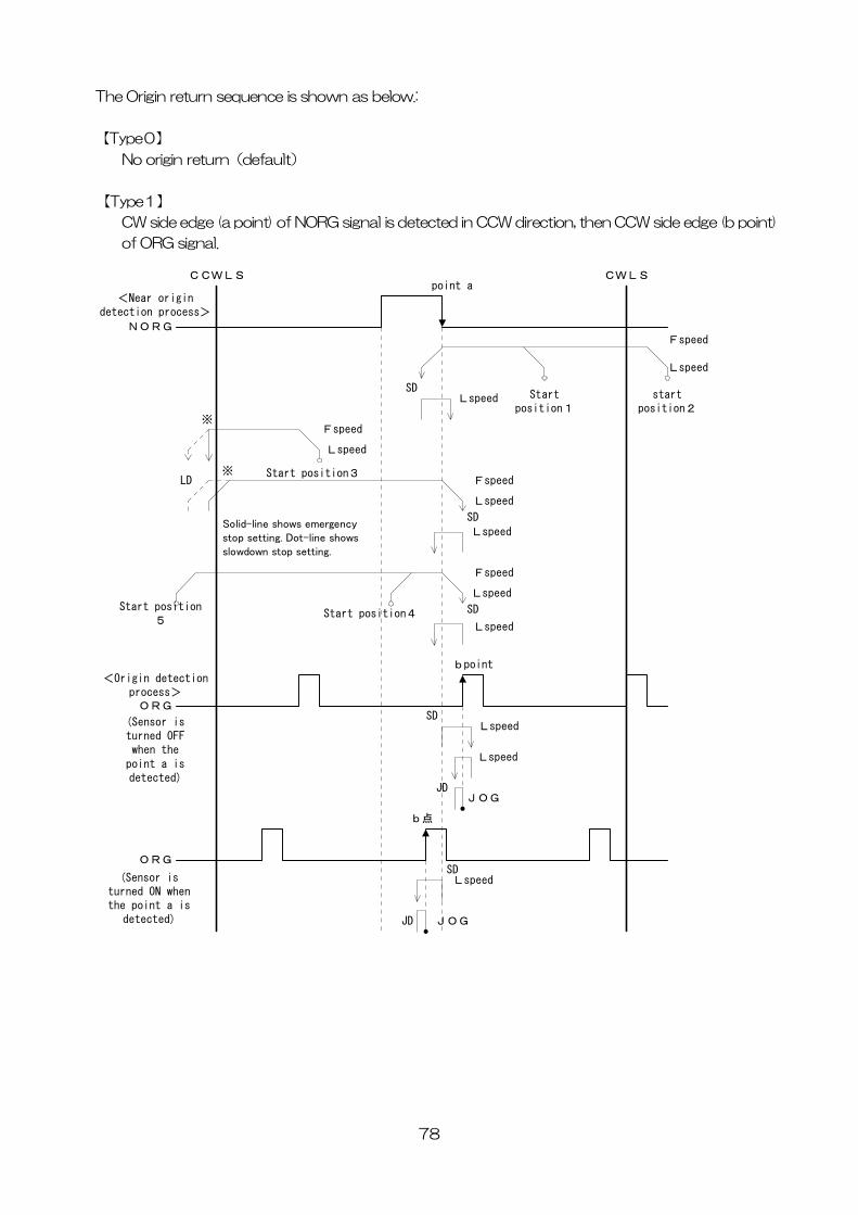
The Origin return sequence is shown as below.:
【Type0】
No origin return(default)
【Type1】
CW side edge (a point) of NORG signal is detected in CCW direction, then CCW side edge (b point)
of ORG signal.
78
CWLS
startposition2
Fspeed
Lspeed
LspeedSD
Start position3LD
Start position4
bpoint
JDJOG
NORG
ORG
(Sensor isturned OFFwhen the
point a isdetected)
<Near origindetection process>
<Origin detectionprocess>
CCWLSpoint a
Startposition1
Fspeed
Lspeed
Fspeed
Lspeed
SD
Lspeed
Start position5
Fspeed
Lspeed
SD
Lspeed
LspeedSD
Lspeed
JD JOG
ORG
(Sensor isturned ON whenthe point a is
detected)
SD
b点
Lspeed
Solid-line shows emergencystop setting. Dot-line showsslowdown stop setting.
※
※
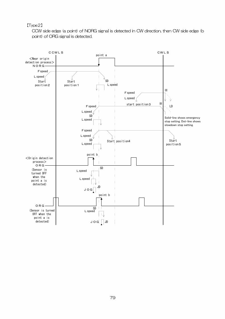
【Type2】
CCW side edge (a point) of NORG signal is detected in CW direction, then CW side edge (b
point) of ORG signal is detected.
CWLS
Start position2
Fspeed
Lspeed
LspeedSD
start position3
NORG
ORG
(Sensor is turned OFF when the
point a is detected)
<Near origin detection process>
<Origin detection process>
CCWLSpoint a
Start position1
Fspeed
Lspeed
Fspeed
Lspeed
SD
ORG
(Sensor is turned OFF when the point a is detected)
LD
Lspeed
Start position4 Start position5
Fspeed
Lspeed
SDLspeed
point b
JDJOG
LspeedSD
Lspeed
JDJOG
SD
point b
Lspeed
※
※
Solid-line shows emergency stop setting. Dot-line shows slowdown stop setting.
79
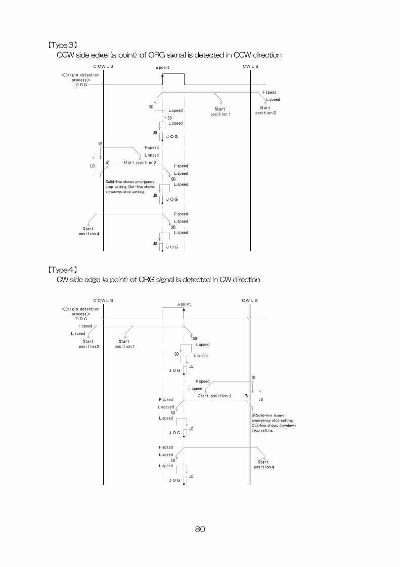
【Type3】
CCW side edge (a point) of ORG signal is detected in CCW direction
80
CWLS
Start position2
Fspeed
Lspeed
LspeedSD
Start position3LD
Start position4
CCWLS apoint
Start position1
Fspeed
Lspeed
Fspeed
Lspeed
SDLspeed
Fspeed
Lspeed
SDLspeed
JDJOG
SDLspeed
ORG
<Origin detection process>
JDJOG
JDJOG
※
※
Solid-line shows emergency stop setting. Dot-line shows slowdown stop setting.
【Type4】
CW side edge (a point) of ORG signal is detected in CW direction.
CWLSCCWLSapoint
ORG
<Origin detection process>
Start position2
Fspeed
Lspeed
Lspeed
SDStart
position1
JDJOG
SD Lspeed
Start position3LD
Fspeed
Lspeed
Fspeed
Lspeeed
SDLspeed
JDJOG
Start position4
Fspeed
Lspeed
SDLspeed
JDJOG
※
※
※Solid-line shows emergency stop setting. Dot-line shows slowdown stop setting.
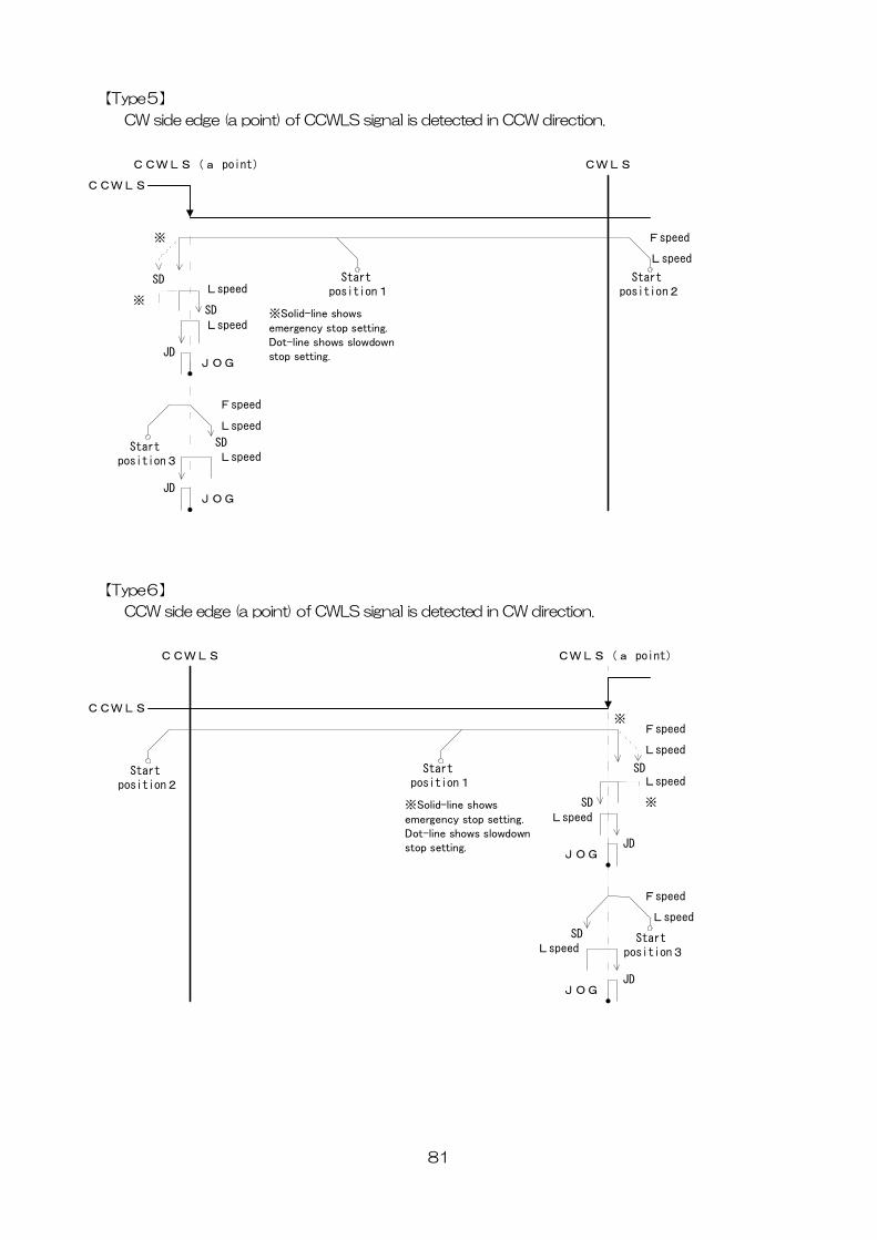
【Type5】
CW side edge (a point) of CCWLS signal is detected in CCW direction.
CCWLS(a point)
CCWLS
Start position2
Fspeed
Lspeed
LspeedSD Start
position1
JDJOG
SD
Lspeed
CWLS
Start position3
Fspeed
Lspeed
SDLspeed
JDJOG
※
※Solid-line shows emergency stop setting. Dot-line shows slowdown stop setting.
※
【Type6】
CCW side edge (a point) of CWLS signal is detected in CW direction.
CCWLS
CCWLS
CWLS(a point)
Start position2
Fspeed
Lspeed
LspeedSDStart
position1
JDJOG
SD
Lspeed
Start position3
Fspeed
Lspeed
SDLspeed
JDJOG
※
※Solid-line shows emergency stop setting. Dot-line shows slowdown stop setting.
※
81
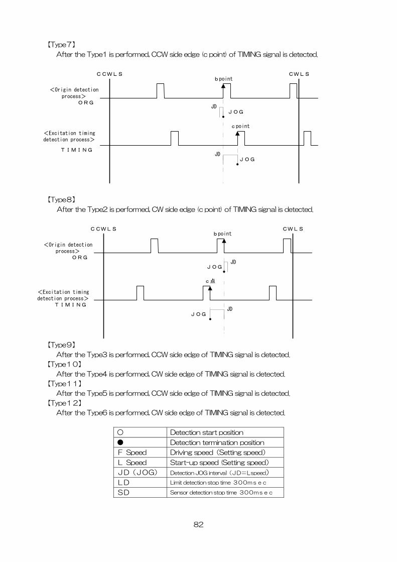
【Type7】
After the Type1 is performed, CCW side edge (c point) of TIMING signal is detected.
CCWLS
<Origin detectionprocess>
JDJOG
CWLSbpoint
cpoint
JDJOG
ORG
<Excitation timingdetection process>
TIMING
【Type8】
After the Type2 is performed, CW side edge (c point) of TIMING signal is detected.
CCWLS
<Origin detectionprocess>
JDJOG
CWLSbpoint
c点
JDJOG
ORG
<Excitation timingdetection process>
TIMING
【Type9】
After the Type3 is performed, CCW side edge of TIMING signal is detected.
【Type10】
After the Type4 is performed, CW side edge of TIMING signal is detected.
【Type11】
After the Type5 is performed, CCW side edge of TIMING signal is detected.
【Type12】
After the Type6 is performed, CW side edge of TIMING signal is detected.
○ Detection start position
● Detection termination position
F Speed Driving speed(Setting speed)
L Speed Start-up speed (Setting speed)
JD(JOG) Detection JOG interval(JD=Lspeed)
LD Limit detection stop time 300msec
SD Sensor detection stop time 300msec
82
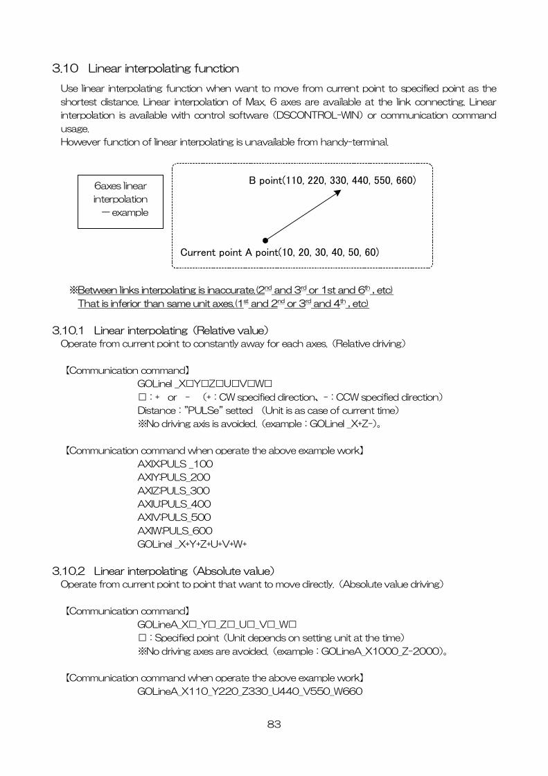
3.10 Linear interpolating function
Use linear interpolating function when want to move from current point to specified point as the
shortest distance. Linear interpolation of Max. 6 axes are available at the link connecting. Linear
interpolation is available with control software(DSCONTROL-WIN)or communication command
usage.
However function of linear interpolating is unavailable from handy-terminal.
83
※Between links interpolating is inaccurate.(2
Current point A point(10, 20, 30, 40, 50, 60)
B point(110, 220, 330, 440, 550, 660)6axes linear
interpolation
一 example
nd and 3rd or 1st and 6th , etc)
That is inferior than same unit axes.(1st and 2nd or 3rd and 4th , etc)
.10.1 Linear interpolating(Relative value)
each axes.(Relative driving)
【Communication command】
Z□U□V□W□
direction、-:CCW specified direction)
【Communication command when operate the above example work】
+V+W+
Absolute value)
ve directly.(Absolute value driving)
【Communication command】
_Z□_U□_V□_W□
setting unit at the time)
2000)。
Communication command when operate the above example work】
3
Operate from current point to constantly away for
GOLineI _X□Y□
□:+ or - (+:CW specified
Distance:”PULSe” setted (Unit is as case of current time)
※No driving axis is avoided.(example:GOLineI _X+Z-)。
AXIX:PULS _100
AXIY:PULS_200
AXIZ:PULS_300
AXIU:PULS_400
AXIV:PULS_500
AXIW:PULS_600
GOLineI _X+Y+Z+U
3.10.2 Linear interpolating(
Operate from current point to point that want to mo
GOLineA_X□_Y□
□:Specified point(Unit depends on
※No driving axes are avoided.(example:GOLineA_X1000_Z-
【
GOLineA_X110_Y220_Z330_U440_V550_W660
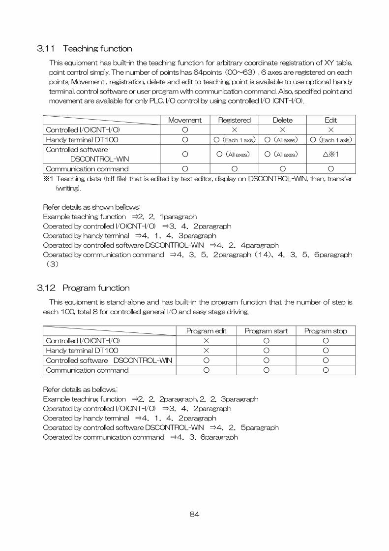
84
3.11 Teaching function
This equipment has built-in the teaching function for arbitrary coordinate registration of XY table,
point control simply. The number of points has 64points(00~63), 6 axes are registered on each
points. Movement , registration, delete and edit to teaching point is available to use optional handy
terminal, control software or user program with communication command. Also, specified point and
movement are available for only PLC, I/O control by using controlled I/O (CNT-I/O).
Movement Registered Delete Edit
Controlled I/O(CNT-I/O) ○ × × ×
Handy terminal DT100 ○ ○(Each 1 axis) ○(All axes) ○(Each 1 axis)
Controlled software
DSCONTROL-WIN ○ ○(All axes) ○(All axes) △※1
Communication command ○ ○ ○ ○
※1 Teaching data (tdf file) that is edited by text editor, display on DSCONTROL-WIN, then, transfer
(writing).
Refer details as shown bellows:
Example teaching function ⇒2.2.1paragraph
Operated by controlled I/O(CNT-I/O) ⇒3.4.2paragraph
Operated by handy terminal ⇒4.1.4.3paragraph
Operated by controlled software DSCONTROL-WIN ⇒4.2.4paragraph
Operated by communication command ⇒4.3.5.2paragraph(14)、4.3.5.6paragraph
(3)
3.12 Program function
This equipment is stand-alone and has built-in the program function that the number of step is
each 100, total 8 for controlled general I/O and easy stage driving.
Program edit Program start Program stop
Controlled I/O(CNT-I/O) × ○ ○
Handy terminal DT100 × ○ ○
Controlled software DSCONTROL-WIN ○ ○ ○
Communication command ○ ○ ○
Refer details as bellows.:
Example teaching function ⇒2.2.2paragraph, 2.2.3paragraph
Operated by controlled I/O(CNT-I/O) ⇒3.4.2paragraph
Operated by handy terminal ⇒4.1.4.2paragraph
Operated by controlled software DSCONTROL-WIN ⇒4.2.5paragraph
Operated by communication command ⇒4.3.6paragraph
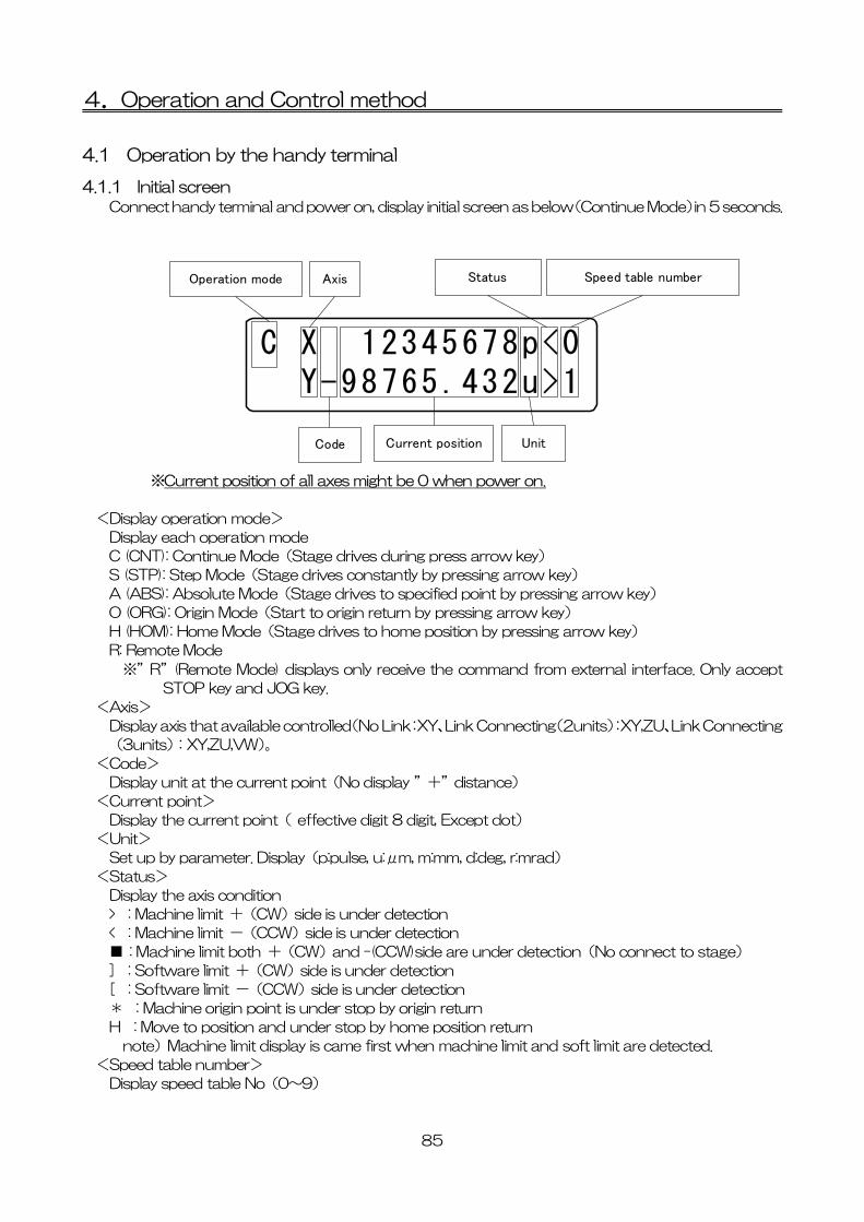
4.Operation and Control method
4.1 Operation by the handy terminal
4.1.1 Initial screen Connect handy terminal and power on, display initial screen as below(Continue Mode)in 5 seconds.
C X 12345678p<0 Y-98765.432u>1
Operation mode Axis
Code Current position
Status
Unit
Speed table number
※Current position of all axes might be 0 when power on.
<Display operation mode>
Display each operation mode
C (CNT): Continue Mode(Stage drives during press arrow key)
S (STP): Step Mode(Stage drives constantly by pressing arrow key)
A (ABS): Absolute Mode(Stage drives to specified point by pressing arrow key)
O (ORG): Origin Mode(Start to origin return by pressing arrow key)
H (HOM): Home Mode(Stage drives to home position by pressing arrow key)
R: Remote Mode
※”R”(Remote Mode) displays only receive the command from external interface. Only accept
STOP key and JOG key.
<Axis>
Display axis that available controlled(No Link:XY、Link Connecting(2units):XY,ZU、Link Connecting
(3units):XY,ZU,VW)。
<Code>
Display unit at the current point(No display ”+”distance)
<Current point>
Display the current point( effective digit 8 digit, Except dot)
<Unit>
Set up by parameter. Display(p:pulse, u:μm, m:mm, d:deg, r:mrad)
<Status>
Display the axis condition
> : Machine limit +(CW)side is under detection
< : Machine limit -(CCW)side is under detection
■ : Machine limit both +(CW)and -(CCW)side are under detection(No connect to stage)
] : Software limit +(CW)side is under detection
[ : Software limit -(CCW)side is under detection
* : Machine origin point is under stop by origin return
H : Move to position and under stop by home position return
note)Machine limit display is came first when machine limit and soft limit are detected.
<Speed table number>
Display speed table No(0~9)
85
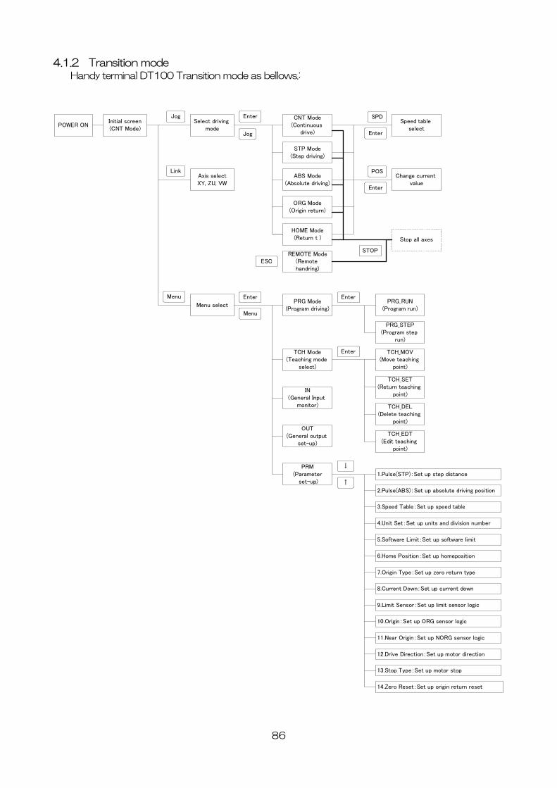
4.1.2 Transition mode Handy terminal DT100 Transition mode as bellows.:
POWER ON
JogInitial screen(CNT Mode)
Select driving mode
Enter CNT Mode(Continuous
drive)
STP Mode(Step driving)
ABS Mode(Absolute driving)
ORG Mode(Origin return)
HOME Mode(Return t )
REMOTE Mode(Remote handring)
Jog
Axis selectXY, ZU, VW
Link
Speed table select
SPD
Enter
ESC
Change current value
POS
Enter
Stop all axes
STOP
Menu select
Menu Enter
Menu
PRG Mode(Program driving)
TCH Mode(Teaching mode
select)
EnterPRG_RUN
(Program run)
PRG_STEP(Program step
run)
Enter TCH_MOV(Move teaching
point)
TCH_SET(Return teaching
point)
TCH_DEL(Delete teaching
point)
TCH_EDT(Edit teaching
point)
IN(General Input
monitor)
OUT(General output
set-up)
PRM(Parameter
set-up)1.Pulse(STP):Set up step distance
2.Pulse(ABS):Set up absolute driving position
3.Speed Table:Set up speed table
4.Unit Set:Set up units and division number
5.Software Limit:Set up software limit
6.Home Position:Set up homeposition
7.Origin Type:Set up zero return type
8.Current Down:Set up current down
9.Limit Sensor:Set up limit sensor logic
10.Origin:Set up ORG sensor logic
11.Near Origin:Set up NORG sensor logic
12.Drive Direction:Set up motor direction
13.Stop Type:Set up motor stop
14.Zero Reset:Set up origin return reset
↓
↑
86
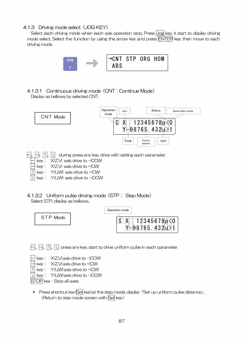
4.1.3 Driving mode select(JOG KEY)
Select each driving mode when each axis operation stop. Press Jog key, it start to display driving
mode select. Select the function by using the arrow key and press ENTER key, then move to each
driving mode.
CNT STP ORG HOM ABS
Jog
7
4.1.3.1 Continuous driving mode(CNT:Continue Mode) Display as bellows by selected CNT.
C X 12345678p<0 Y-98765.432u>1
Operationmode
Axis
Code Currentposition
Status
Unit
Speed table number
CNT Mode
←、→、↑、↓ during press any key, drive with setting each parameter.
← key: X(Z,V) axis drive to -(CCW)
→ key: X(Z,V) axis drive to +(CW)
↑ key: Y(U,W) axis drive to +(CW)
↓ key: Y(U,W) axis drive to -(CCW)
4.1.3.2 Uniform pulse driving mode(STP: Step Mode) Select STP, display as bellows.:
S X 12345678p<0 Y-98765.432u>1
Operation mode
STP Mode
←、→、↑、↓ press any key, start to drive uniform pulse in each parameter.
← key: X(Z,V)axis drive to -(CCW)
→ key: X(Z,V)axis drive to +(CW)
↑ key: Y(U,W)axis drive to +(CW)
↓ key: Y(U,W)axis drive to -(CCW)
STOP key:Stop all axes
* Press shortcut key(Set key)at the step mode, display「Set up uniform pulse distance」.
(Return to step mode screen with Set key)
87
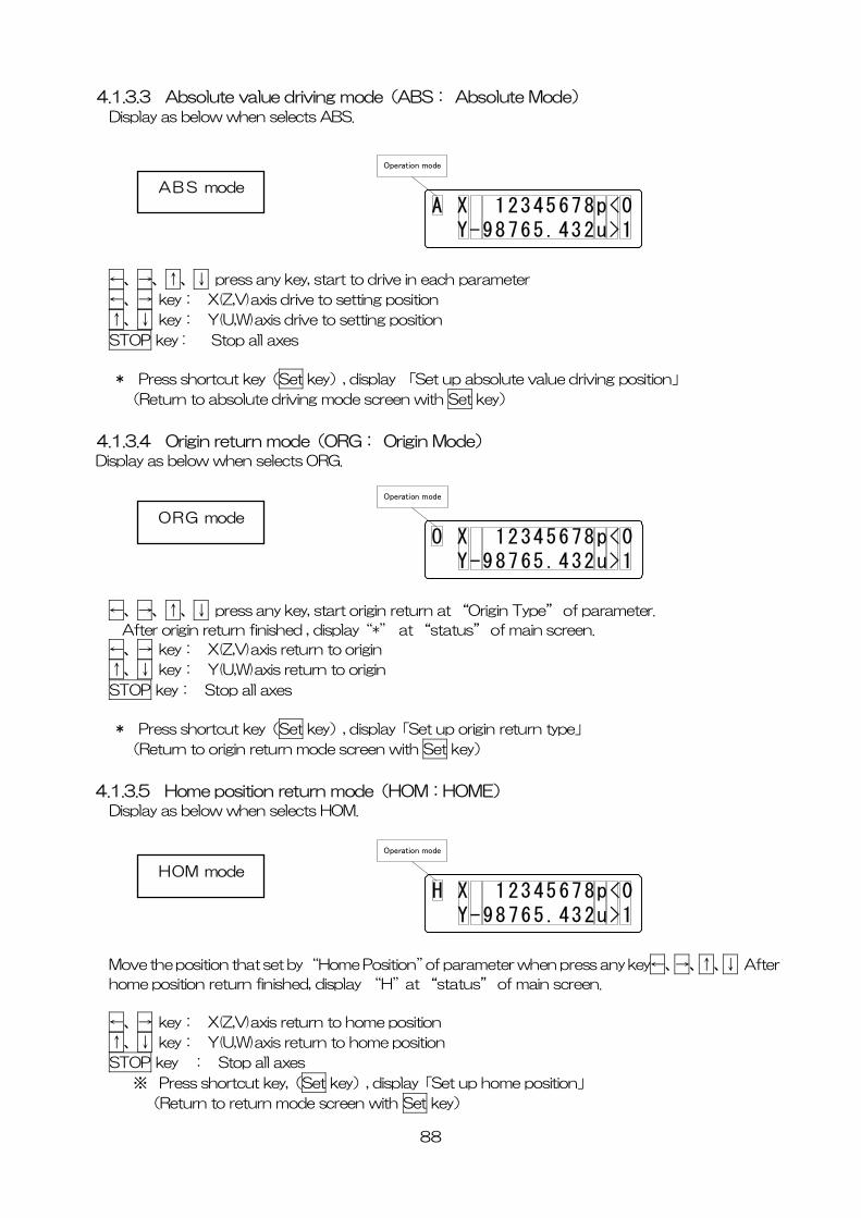
4.1.3.3 Absolute value driving mode(ABS: Absolute Mode) Display as below when selects ABS.
A X 12345678p<0 Y-98765.432u>1
Operation mode
ABS mode
←、→、↑、↓ press any key, start to drive in each parameter
←、→ key: X(Z,V)axis drive to setting position
↑、↓ key: Y(U,W)axis drive to setting position
STOP key : Stop all axes
* Press shortcut key(Set key), display 「Set up absolute value driving position」
(Return to absolute driving mode screen with Set key)
4.1.3.4 Origin return mode(ORG: Origin Mode) Display as below when selects ORG.
O X 12345678p<0 Y-98765.432u>1
Operation mode
ORG mode
←、→、↑、↓ press any key, start origin return at “Origin Type” of parameter.
After origin return finished , display“*” at “status” of main screen.
←、→ key: X(Z,V)axis return to origin
↑、↓ key: Y(U,W)axis return to origin
STOP key: Stop all axes
* Press shortcut key(Set key), display「Set up origin return type」
(Return to origin return mode screen with Set key)
4.1.3.5 Home position return mode(HOM:HOME) Display as below when selects HOM.
H X 12345678p<0 Y-98765.432u>1
Operation mode
HOM mode
Move the position that set by “Home Position”of parameter when press any key←、→、↑、↓ After
home position return finished, display “H”at “status” of main screen.
←、→ key: X(Z,V)axis return to home position
↑、↓ key: Y(U,W)axis return to home position
STOP key : Stop all axes
※ Press shortcut key,(Set key), display「Set up home position」
(Return to return mode screen with Set key)
88
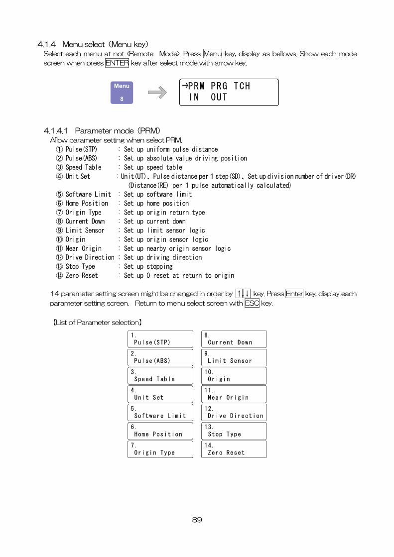
4.1.4 Menu select(Menu key)
Select each menu at not <Remote Mode>. Press Menu key, display as bellows. Show each mode
screen when press ENTER key after select mode with arrow key.
PRM PRG TCH IN OUT
Menu
8
4.1.4.1 Parameter mode(PRM)
Allow parameter setting when select PRM.
① Pulse(STP) : Set up uniform pulse distance
② Pulse(ABS) : Set up absolute value driving position
③ Speed Table : Set up speed table
④ Unit Set : Unit(UT)、Pulse distance per 1 step(SD)、Set up division number of driver(DR)
(Distance(RE) per 1 pulse automatically calculated)
⑤ Software Limit : Set up software limit
⑥ Home Position : Set up home position
⑦ Origin Type : Set up origin return type
⑧ Current Down : Set up current down
⑨ Limit Sensor : Set up limit sensor logic
⑩ Origin : Set up origin sensor logic
⑪ Near Origin : Set up nearby origin sensor logic
⑫ Drive Direction : Set up driving direction
⑬ Stop Type : Set up stopping
⑭ Zero Reset : Set up 0 reset at return to origin
14 parameter setting screen might be changed in order by ↑,↓ key. Press Enter key, display each
parameter setting screen. Return to menu select screen with ESC key.
【List of Parameter selection】
8. Current Down
9. Limit Sensor
10. Origin
11. Near Origin
12. Drive Direction
13. Stop Type
14. Zero Reset
1. Pulse(STP)
2. Pulse(ABS)
3. Speed Table
4. Unit Set
5. Software Limit
6. Home Position
7. Origin Type
89
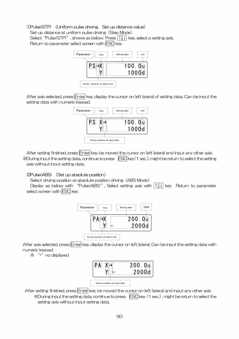
①Pulse(STP) (Uniform pulse driving, Set up distance value)
Set up distance at uniform pulse driving(Step Mode)
Select“Pulse(STP)”, shows as below.: Press ↑,↓ key, select a setting axis.
Return to parameter select screen with ESC key.
PS X 100.0u Y 1000d
Parametor Axis Setting data unit
Cursor position at select axis
After axis selected, press Enter key, display the cursor on left lateral of setting data. Can be input the
setting data with numeric keypad.
PS X 100.0u Y 1000d
Parameter Axis Setting data unit
Cursor position at input data
After setting finished, press Enter key, be moved the cursor on left lateral and input any other axis.
※During input the setting data, continue to press ESC key(1 sec.), might be return to select the setting
axis without input setting data.
②Pulse(ABS) (Set up absolute position)
Select driving position at absolute position driving(ABS Mode)
Display as below with “Pulse(ABS)”, Select setting axis with ↑,↓ key. Return to parameter
select screen with ESC key.
PA X 200.0u Y - 2000d
Parameter Axis Setting data Unit
Cursor position at select axis
After axis selected, press Enter key, display the cursor on left lateral. Can be input the setting data with
numeric keypad.
※ “+”no displayed
PA X 200.0u Y - 2000d
Carsor position at input data
After setting finished, press Enter key, be moved the cursor on left-lateral and input any other axis
※During input the setting data, continue to press ESC key(1 sec.), might be return to select the
setting axis without input setting data.
90
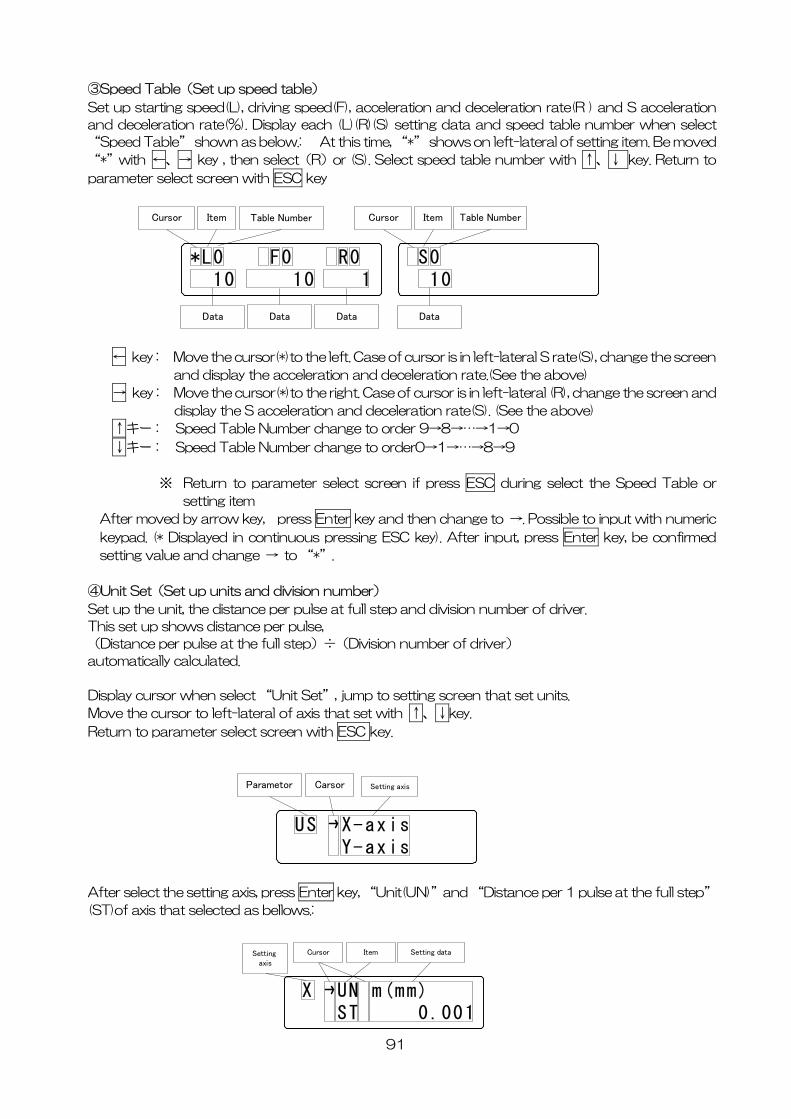
③Speed Table(Set up speed table)
Set up starting speed(L), driving speed(F), acceleration and deceleration rate(R ) and S acceleration
and deceleration rate(%). Display each (L)(R)(S) setting data and speed table number when select
“Speed Table” shown as below.: At this time, “*” shows on left-lateral of setting item. Be moved
“*”with ←、→ key , then select(R)or (S). Select speed table number with ↑、↓ key. Return to
parameter select screen with ESC key
*L0 F0 R0 10 10 1
Data Data
Cursor
Data
Item Table Number
S0 10
Cursor
Data
Item Table Number
← key: Move the cursor(*)to the left. Case of cursor is in left-lateral S rate(S), change the screen
and display the acceleration and deceleration rate.(See the above)
→ key: Move the cursor(*)to the right. Case of cursor is in left-lateral (R), change the screen and
display the S acceleration and deceleration rate(S). (See the above)
↑キー: Speed Table Number change to order 9→8→…→1→0
↓キー: Speed Table Number change to order0→1→…→8→9
※ Return to parameter select screen if press ESC during select the Speed Table or
setting item
After moved by arrow key, press Enter key and then change to →. Possible to input with numeric
keypad. (* Displayed in continuous pressing ESC key). After input, press Enter key, be confirmed
setting value and change → to “*”.
④Unit Set(Set up units and division number)
Set up the unit, the distance per pulse at full step and division number of driver.
This set up shows distance per pulse,
(Distance per pulse at the full step)÷(Division number of driver)
automatically calculated.
Display cursor when select “Unit Set”, jump to setting screen that set units.
Move the cursor to left-lateral of axis that set with ↑、↓key.
Return to parameter select screen with ESC key.
US X-axis Y-axis
Parametor Carsor Setting axis
After select the setting axis, press Enter key, “Unit(UN)”and “Distance per 1 pulse at the full step”
(ST)of axis that selected as bellows.:
X UN m(mm) ST 0.001
Setting axis
Cursor Setting dataItem
91
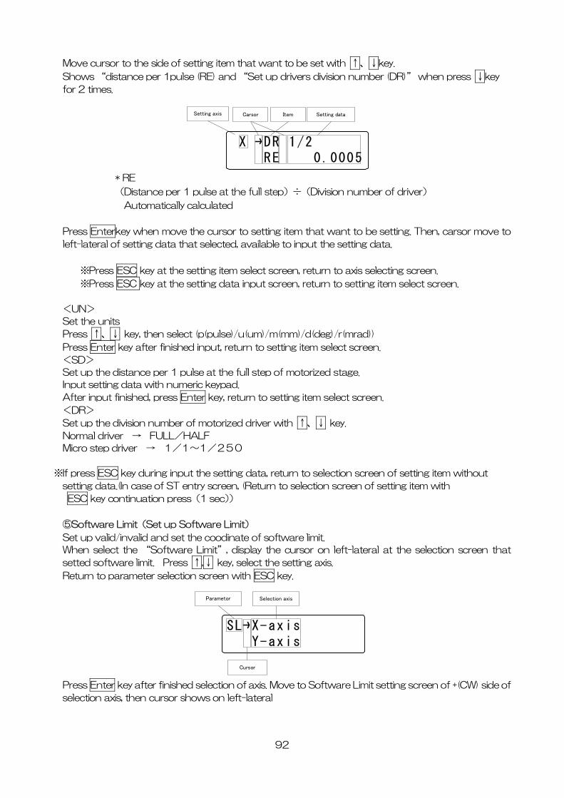
Move cursor to the side of setting item that want to be set with ↑、↓key.
Shows “distance per 1pulse (RE) and “Set up drivers division number (DR)” when press ↓key
for 2 times.
X DR 1/2 RE 0.0005
Setting axis Carsor Setting dataItem
* RE
(Distance per 1 pulse at the full step)÷(Division number of driver)
Automatically calculated
Press Enterkey when move the cursor to setting item that want to be setting. Then, carsor move to
left-lateral of setting data that selected, available to input the setting data.
※Press ESC key at the setting item select screen, return to axis selecting screen.
※Press ESC key at the setting data input screen, return to setting item select screen.
<UN>
Set the units
Press ↑、↓ key, then select (p(pulse)/u(um)/m(mm)/d(deg)/r(mrad))
Press Enter key after finished input, return to setting item select screen.
<SD>
Set up the distance per 1 pulse at the full step of motorized stage.
Input setting data with numeric keypad.
After input finished, press Enter key, return to setting item select screen.
<DR>
Set up the division number of motorized driver with ↑、↓ key.
Normal driver → FULL/HALF
Micro step driver → 1/1~1/250
※If press ESC key during input the setting data, return to selection screen of setting item without
setting data.(In case of ST entry screen, (Return to selection screen of setting item with
ESC key continuation press(1 sec))
⑤Software Limit(Set up Software Limit)
Set up valid/invalid and set the coodinate of software limit.
When select the “Software Limit”, display the cursor on left-lateral at the selection screen that
setted software limit. Press ↑,↓ key, select the setting axis.
Return to parameter selection screen with ESC key.
SL X-axis Y-axis
Parametor Selection axis
Cursor
Press Enter key after finished selection of axis. Move to Software Limit setting screen of +(CW) side of
selection axis, then cursor shows on left-lateral
92
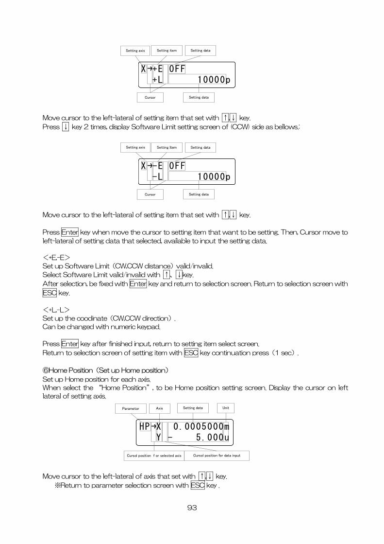
X +E OFF +L 10000p
Setting axis Setting data
Cursor
Setting item
Setting data
Move cursor to the left-lateral of setting item that set with ↑,↓ key.
Press ↓ key 2 times, display Software Limit setting screen of (CCW) side as bellows.:
X -E OFF -L 10000p
Setting axis Setting data
Cursor
Setting Item
Setting data
Move cursor to the left-lateral of setting item that set with ↑,↓ key.
Press Enter key when move the cursor to setting item that want to be setting. Then, Cursor move to
left-lateral of setting data that selected, available to input the setting data.
<+E,-E>
Set up Software Limit(CW,CCW distance)valid/invalid.
Select Software Limit valid/invalid with ↑、↓key.
After selection, be fixed with Enter key and return to selection screen. Return to selection screen with
ESC key.
<+L,-L>
Set up the coodinate(CW,CCW direction).
Can be changed with numeric keypad.
Press Enter key after finished input, return to setting item select screen.
Return to selection screen of setting item with ESC key continuation press(1 sec).
⑥Home Position(Set up Home position)
Set up Home position for each axis.
When select the “Home Position”, to be Home position setting screen. Display the cursor on left
lateral of setting axis.
ove cursor to the left-lateral of axis that set with ↑,↓ key.
HP X 0.0005000m Y - 5.000u
Parametor Axis Setting data Unit
Cursol position f or selected axis Cursol position for data input
M
※Return to parameter selection screen with ESC key .
93
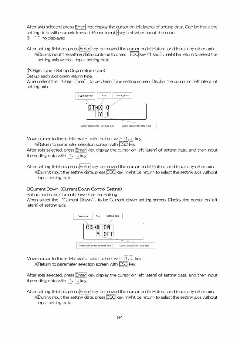
94
fter axis selected, press Enter key, display the cursor on left lateral of setting data. Can be input the A
setting data with numeric keypad. Please input –key first when input the code.
※ “+”no displayed
fter setting finished, press Enter key, be moved the cursor on left-lateral and input any other axis A
※During input the setting data, continue to press ESC key(1 sec.), might be return to select the
setting axis without input setting data.
⑦O in Type(Set up Origin return type)
be Origin Type setting screen. Display the cursor on left lateral of
ove cursor to the left-lateral of axis that set with ↑,↓ key.
rig
Set up each axis origin return type.
When select the “Origin Type”, to
setting axis.
M
※Return to parameter selection screen with ESC key.
Aft eft-lateral of setting data, and then input er axis selected, press Enter key, display the cursor on l
the setting data with ↑、↓key.
fter setting finished, press Enter key, be moved the cursor on left-lateral and input any other axis A
※During input the setting data, press ESC key, might be return to select the setting axis without
input setting data.
⑧Current Down(Current Down Control Setting)
nt down setting screen. Display the cursor on left
ove cursor to the left-lateral of axis that set with ↑,↓ key.
Set up each axis Current Down Control Setting.
When select the “Current Down”, to be Curre
OT X 0 Y 1
Parameter Axis Setting data
Cursol position for selected axis Cursol position for data input
CD X ON Y OFF
Parametor Axis Setting data
Cursol position for selected axis Cursol position for input data
lateral of setting axis.
M
※Return to parameter selection screen with ESC key.
After axis selected, press Enter key, display the cursor on left-lateral of setting data, and then input
the setting data with ↑、↓key.
fter setting finished, press Enter key, be moved the cursor on left-lateral and input any other axis A
※During input the setting data, press ESC key, might be return to select the setting axis without
input setting data.
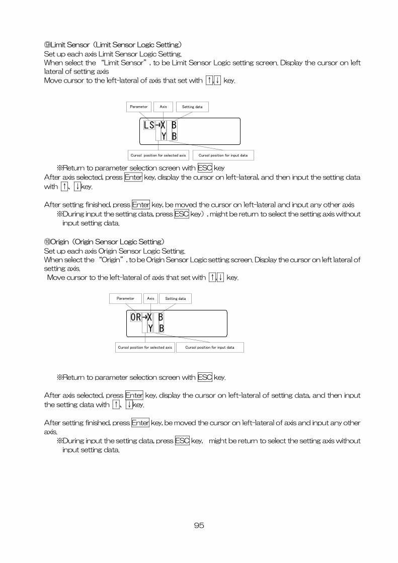
⑨Limit Sensor(Limit Sensor Logic Setting)
Set up each axis Limit Sensor Logic Setting.
When select the “Limit Sensor”, to be Limit Sensor Logic setting screen. Display the cursor on left
lateral of setting axis
Move cursor to the left-lateral of axis that set with ↑,↓ key.
LS X B Y B
Parametor Axis Setting data
Cursol position for selected axis Cursol position for input data
※Return to parameter selection screen with ESC key
After axis selected, press Enter key, display the cursor on left-lateral, and then input the setting data
with ↑、↓key.
After setting finished, press Enter key, be moved the cursor on left-lateral and input any other axis
※During input the setting data, press ESC key), might be return to select the setting axis without
input setting data.
⑩Origin(Origin Sensor Logic Setting)
Set up each axis Origin Sensor Logic Setting.
When select the “Origin”, to be Origin Sensor Logic setting screen. Display the cursor on left lateral of
setting axis.
Move cursor to the left-lateral of axis that set with ↑,↓ key.
OR X B Y B
Parametor Axis Setting data
Cursol position for selected axis Cursol position for input data
※Return to parameter selection screen with ESC key.
After axis selected, press Enter key, display the cursor on left-lateral of setting data, and then input
the setting data with ↑、↓key.
After setting finished, press Enter key, be moved the cursor on left-lateral of axis and input any other
axis.
※During input the setting data, press ESC key, might be return to select the setting axis without
input setting data.
95
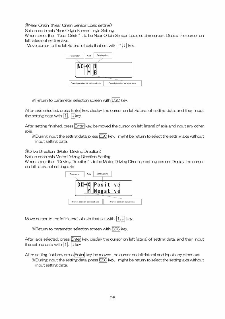
⑪Near Origin(Near Origin Sensor Logic setting)
Set up each axis Near Origin Sensor Logic Setting
When select the “Near Origin”, to be Near Origin Sensor Logic setting screen. Display the cursor on
left lateral of setting axis.
Move cursor to the left-lateral of axis that set with ↑,↓ key.
NO X B Y B
Parametor Axis Setting data
Cursol position for selected axis Cursol position for input data
※Return to parameter selection screen with ESC key.
After axis selected, press Enter key, display the cursor on left-lateral of setting data, and then input
the setting data with ↑、↓key.
After setting finished, press Enter key, be moved the cursor on left-lateral of axis and input any other
axis.
※During input the setting data, press ESC key, might be return to select the setting axis without
input setting data.
⑫Drive Direction(Motor Driving Direction)
Set up each axis Motor Driving Direction Setting.
When select the “Driving Direction”, to be Motor Driving Direction setting screen. Display the cursor
on left lateral of setting axis.
DD X Positive Y Negative
Parametor Axis Setting data
Cursol position selected axis Cursol position input data
Move cursor to the left-lateral of axis that set with ↑,↓ key.
※Return to parameter selection screen with ESC key.
After axis selected, press Enter key, display the cursor on left-lateral of setting data, and then input
the setting data with ↑、↓key.
After setting finished, press Enter key, be moved the cursor on left-lateral and input any other axis
※During input the setting data, press ESC key, might be return to select the setting axis without
input setting data.
96
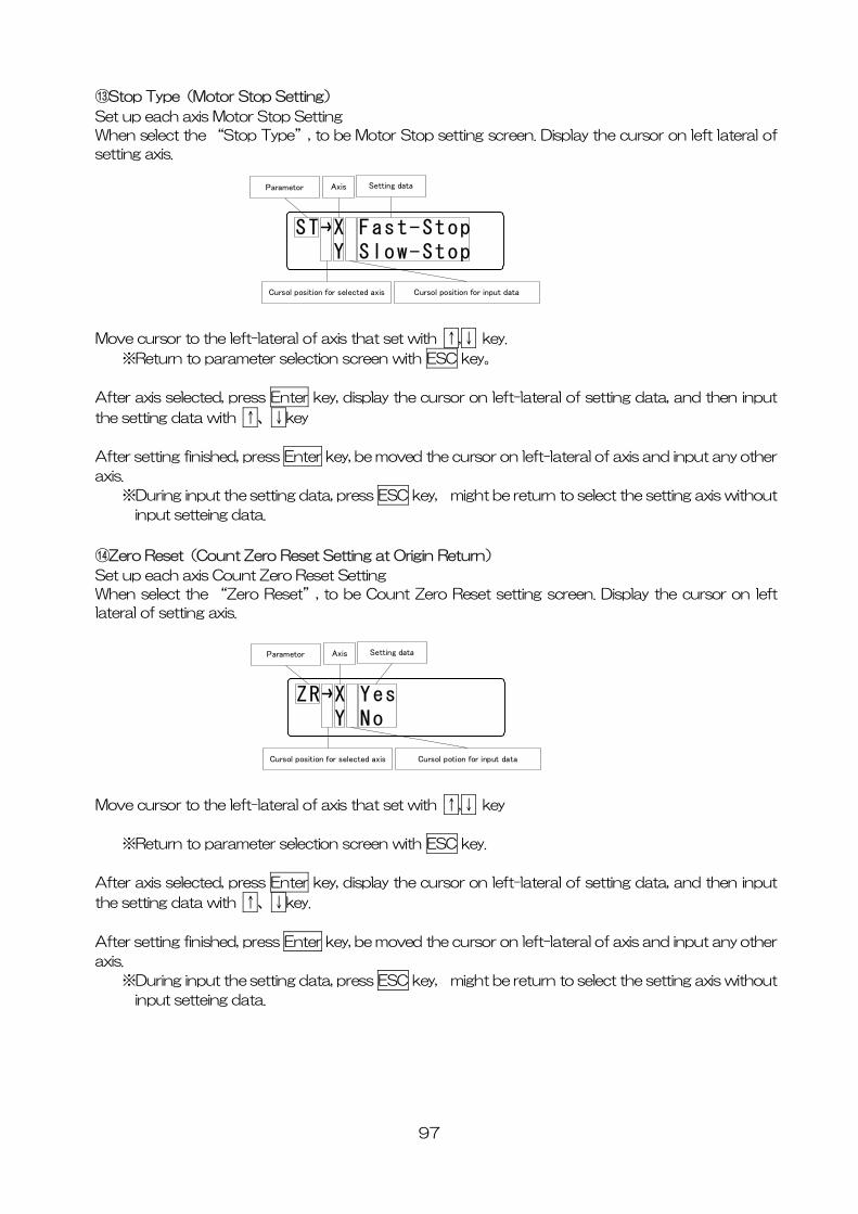
⑬Stop Type(Motor Stop Setting)
Set up each axis Motor Stop Setting
When select the “Stop Type”, to be Motor Stop setting screen. Display the cursor on left lateral of
setting axis.
ST X Fast-Stop Y Slow-Stop
Parametor Axis Setting data
Cursol position for selected axis Cursol position for input data
Move cursor to the left-lateral of axis that set with ↑,↓ key.
※Return to parameter selection screen with ESC key。
After axis selected, press Enter key, display the cursor on left-lateral of setting data, and then input
the setting data with ↑、↓key
After setting finished, press Enter key, be moved the cursor on left-lateral of axis and input any other
axis.
※During input the setting data, press ESC key, might be return to select the setting axis without
input setteing data.
⑭Zero Reset(Count Zero Reset Setting at Origin Return)
Set up each axis Count Zero Reset Setting
When select the “Zero Reset”, to be Count Zero Reset setting screen. Display the cursor on left
lateral of setting axis.
ZR X Yes Y No
Parametor Axis Setting data
Cursol position for selected axis Cursol potion for input data
Move cursor to the left-lateral of axis that set with ↑,↓ key
※Return to parameter selection screen with ESC key.
After axis selected, press Enter key, display the cursor on left-lateral of setting data, and then input
the setting data with ↑、↓key.
After setting finished, press Enter key, be moved the cursor on left-lateral of axis and input any other
axis.
※During input the setting data, press ESC key, might be return to select the setting axis without
input setteing data.
97
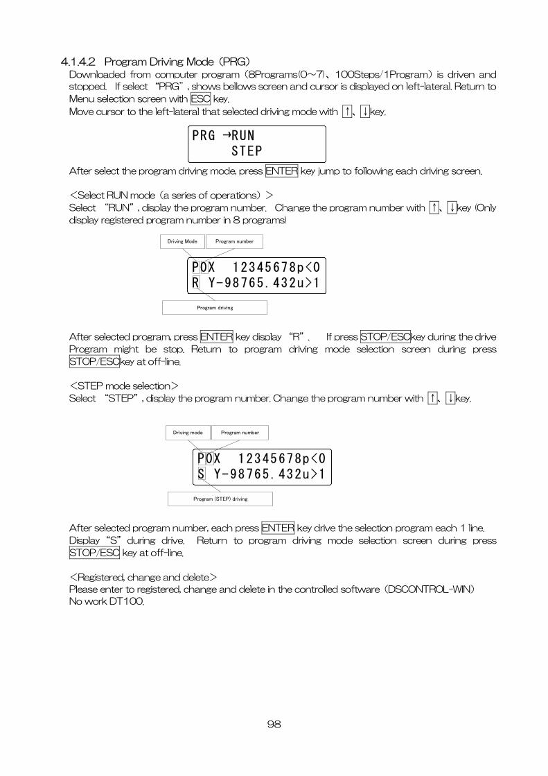
4.1.4.2 Program Driving Mode(PRG) Downloaded from computer program(8Programs(0~7)、100Steps/1Program)is driven and
stopped. If select “PRG”, shows bellows screen and cursor is displayed on left-lateral. Return to
Menu selection screen with ESC key.
Move cursor to the left-lateral that selected driving mode with ↑、↓key.
PRG RUN STEP
After select the program driving mode, press ENTER key jump to following each driving screen.
<Select RUN mode(a series of operations)>
Select “RUN”, display the program number. Change the program number with ↑、↓key (Only
display registered program number in 8 programs)
P0X 12345678p<0R Y-98765.432u>1
Driving Mode Program number
Program driving
After selected program, press ENTER key display “R”. If press STOP/ESCkey during the drive
Program might be stop. Return to program driving mode selection screen during press
STOP/ESCkey at off-line.
<STEP mode selection>
Select “STEP”, display the program number. Change the program number with ↑、↓key.
P0X 12345678p<0S Y-98765.432u>1
Driving mode Program number
Program (STEP) driving
After selected program number, each press ENTER key drive the selection program each 1 line.
Display “S” during drive. Return to program driving mode selection screen during press
STOP/ESC key at off-line.
<Registered, change and delete>
Please enter to registered, change and delete in the controlled software(DSCONTROL-WIN)
No work DT100.
98
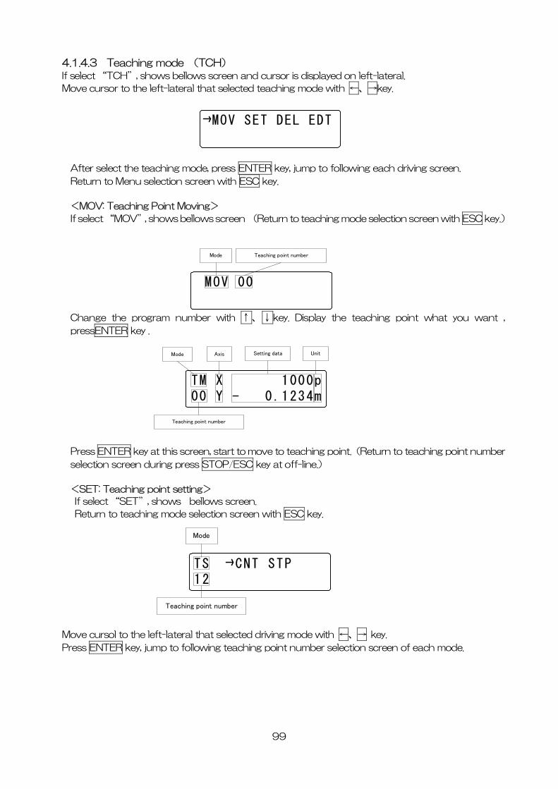
4.1.4.3 Teaching mode (TCH) If select “TCH”, shows bellows screen and cursor is displayed on left-lateral.
Move cursor to the left-lateral that selected teaching mode with ←、→key.
MOV SET DEL EDT
After select the teaching mode, press ENTER key, jump to following each driving screen.
Return to Menu selection screen with ESC key.
<MOV: Teaching Point Moving>
If select “MOV”, shows bellows screen (Return to teaching mode selection screen with ESC key.)
MOV 00
Mode Teaching point number
Change the program number with ↑、↓key. Display the teaching point what you want ,
pressENTER key .
TM X 1000p00 Y - 0.1234m
Mode Axis Setting data Unit
Teaching point number
Press ENTER key at this screen, start to move to teaching point.(Return to teaching point number
selection screen during press STOP/ESC key at off-line.)
<SET: Teaching point setting>
If select “SET”, shows bellows screen.
Return to teaching mode selection screen with ESC key.
TS CNT STP12
Mode
Teaching point number
Move cursol to the left-lateral that selected driving mode with ←、→ key.
Press ENTER key, jump to following teaching point number selection screen of each mode.
99
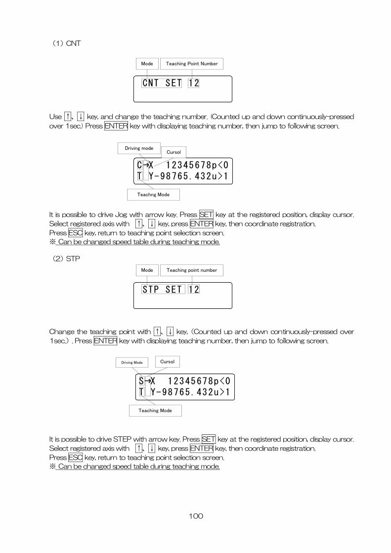
(1)CNT
CNT SET 12
Mode Teaching Point Number
Use ↑、↓ key, and change the teaching number. (Counted up and down continuously-pressed
over 1sec.) Press ENTER key with displaying teaching number, then jump to following screen.
It is possible to drive Jog with arrow key. Press SET key at the registered position, display cursor.
C X 12345678p<0T Y-98765.432u>1
Driving modeCursol
Teachng Mode
Select registered axis with ↑、↓ key, press ENTER key, then coordinate registration.
Press ESC key, return to teaching point selection screen.
※ Can be changed speed table during teaching mode.
(2)STP
hange the teaching point with ↑、↓ key,(Counted up and down continuously-pressed over
STP SET 12
Mode Teaching point number
C
1sec.). Press ENTER key with displaying teaching number, then jump to following screen.
S X 12345678p<0T Y-98765.432u>1
Teaching Mode
Driving Mode Cursol
It is possible to drive STEP with arrow key. Press SET key at the registered position, display cursor.
Select registered axis with ↑、↓ key, press ENTER key, then coordinate registration.
Press ESC key, return to teaching point selection screen.
※ Can be changed speed table during teaching mode.
100
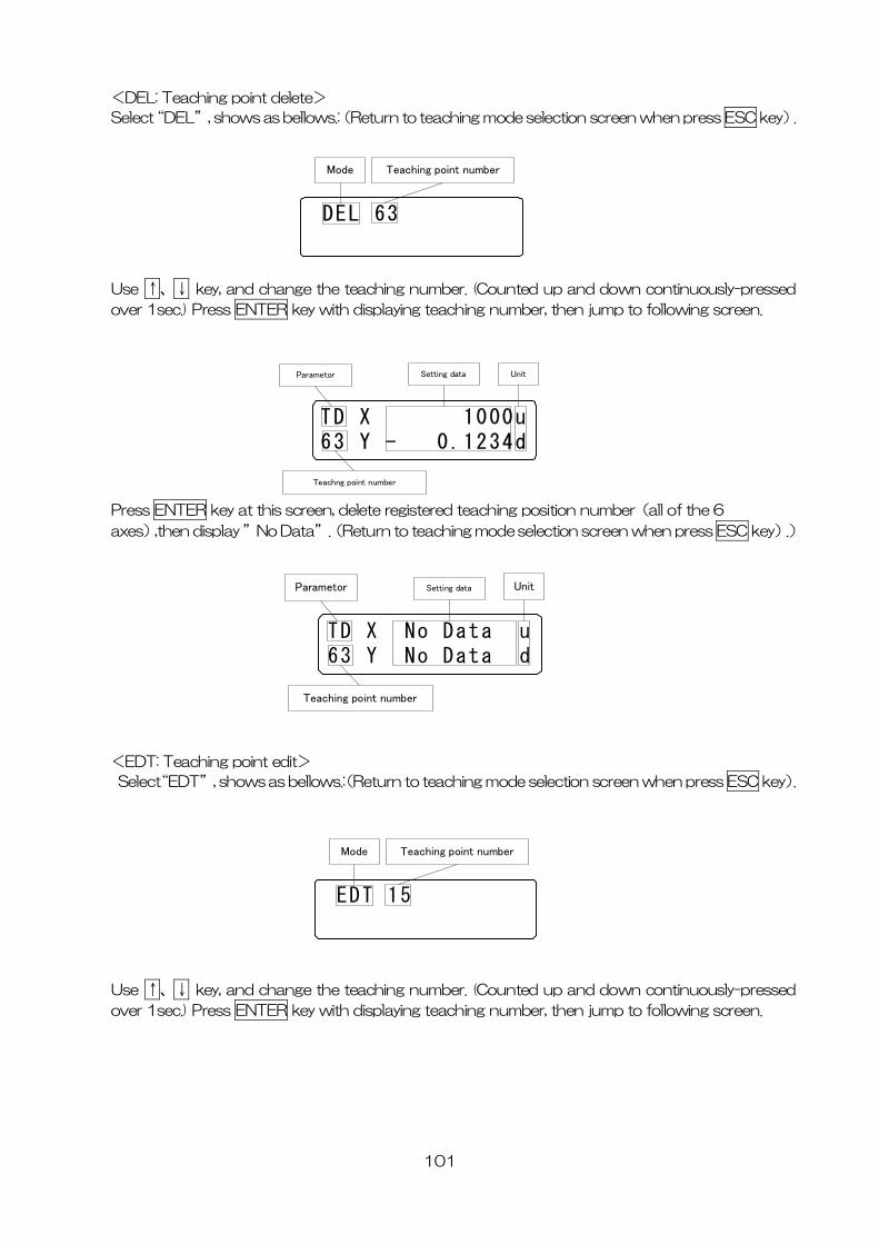
101
DEL: Teaching point delete>
.:(Return to teaching mode selection screen when press ESC key).
<
Select“DEL”, shows as bellows
DEL 63
Mode Teaching point number
se ↑、↓ key, and change the teaching number. (Counted up and down continuously-pressed U
over 1sec.) Press ENTER key with displaying teaching number, then jump to following screen.
Press ENTER key at this ition number(all of the 6
TD X 1000u63 Y - 0.1234d
Parametor Setting data Unit
Teachng point number
screen, delete registered teaching pos
axes),then display ”No Data”.(Return to teaching mode selection screen when press ESC key).)
TD X No Data u63 Y No Data d
Parametor Setting data
Teaching point number
Unit
EDT: Teaching point edit>
ws.:(Return to teaching mode selection screen when press ESC key).
<
Select“EDT”, shows as bello
EDT 15
Mode Teaching point number
se ↑、↓ key, and change the teaching number. (Counted up and down continuously-pressed U
over 1sec.) Press ENTER key with displaying teaching number, then jump to following screen.
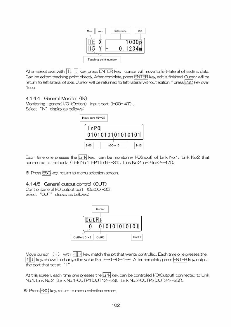
TE X 1000p15 Y - 0.1234m
Mode Axis Setting data Unit
Teachng point number
After select axis with ↑、↓ key, press ENTER key, cursor will move to left-lateral of setting data.
Can be edited teaching point directly. After complete, press ENTER key, edit is finished. Cursor will be
return to left-lateral of axis. Cursor will be returned to left-lateral without edition if press ESC key over
1sec.
4.1.4.4 General Monitor(IN) Monitoring general I/O(Option) input port(In00~47).
Select “IN” display as bellows.:
InP00101010101010101
Input port (0~2)
In00~15In00 In15
Each time one presses the Link key, can be monitoring I/O(Input) of Link No.1、Link No.2 that
connected to the body.(Link No.1=InP1(In16~31)、Link No.2=InP2(In32~47))。
※ Press ESC key, return to menu selection screen.
4.1.4.5 General output control(OUT) Control general I/O output port (Out00~35).
Select “OUT” display as bellows.:
OutP 0 010101010101
Out00 Out11OutPort 0~2
Cursor
Move cursor (↓) with ←,→ key, match the pit that wants controlled. Each time one presses the
↑,↓ key, shows to change the value like …→1→0→1→….After complete, press ENTER key, output
the port that set at “1”.
At this screen, each time one presses the Link key, can be controlled I/O(Output) connected to Link
No.1, Link No.2.(Link No.1=OUTP1(OUT12~23)、Link No.2=OUTP2(OUT24~35))。
※ Press ESC key, return to menu selection screen.
102
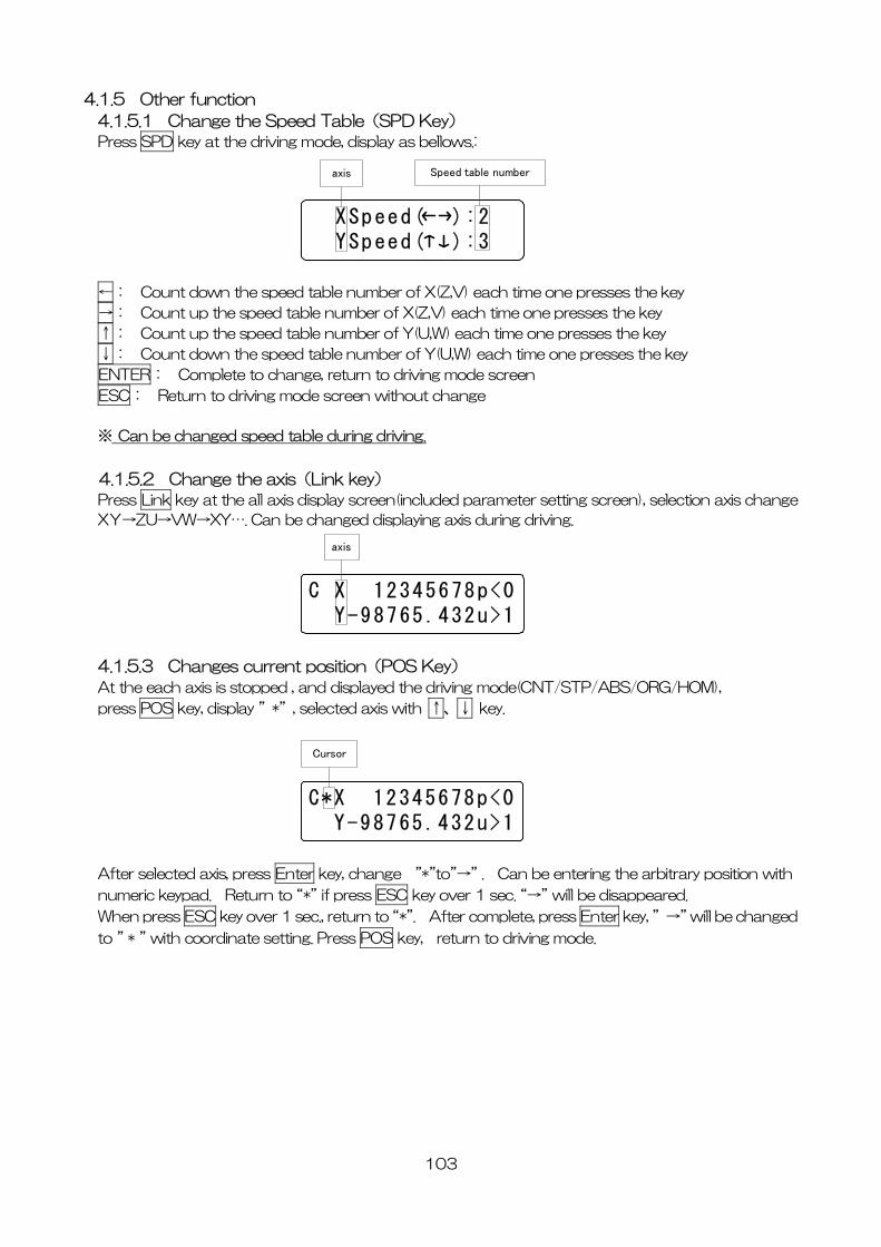
4.1.5 Other function
4.1.5.1 Change the Speed Table(SPD Key) Press SPD key at the driving mode, display as bellows.:
XSpeed( ):2 YSpeed( ):3
axis Speed table number
←: Count down the speed table number of X(Z,V) each time one presses the key
→: Count up the speed table number of X(Z,V) each time one presses the key
↑: Count up the speed table number of Y(U,W) each time one presses the key
↓: Count down the speed table number of Y(U,W) each time one presses the key
ENTER: Complete to change, return to driving mode screen
ESC: Return to driving mode screen without change
※ Can be changed speed table during driving.
4.1.5.2 Change the axis(Link key) Press Link key at the all axis display screen(included parameter setting screen), selection axis change
XY→ZU→VW→XY…. Can be changed displaying axis during driving.
C X 12345678p<0 Y-98765.432u>1
axis
4.1.5.3 Changes current position(POS Key)
At the each axis is stopped , and displayed the driving mode(CNT/STP/ABS/ORG/HOM),
press POS key, display ”*”, selected axis with ↑、↓ key.
C*X 12345678p<0 Y-98765.432u>1
Cursor
After selected axis, press Enter key, change ”*”to”→” . Can be entering the arbitrary position with
numeric keypad. Return to “*” if press ESC key over 1 sec. “→” will be disappeared.
When press ESC key over 1 sec., return to “*”. After complete, press Enter key, ” →” will be changed
to ” * ” with coordinate setting. Press POS key, return to driving mode.
103
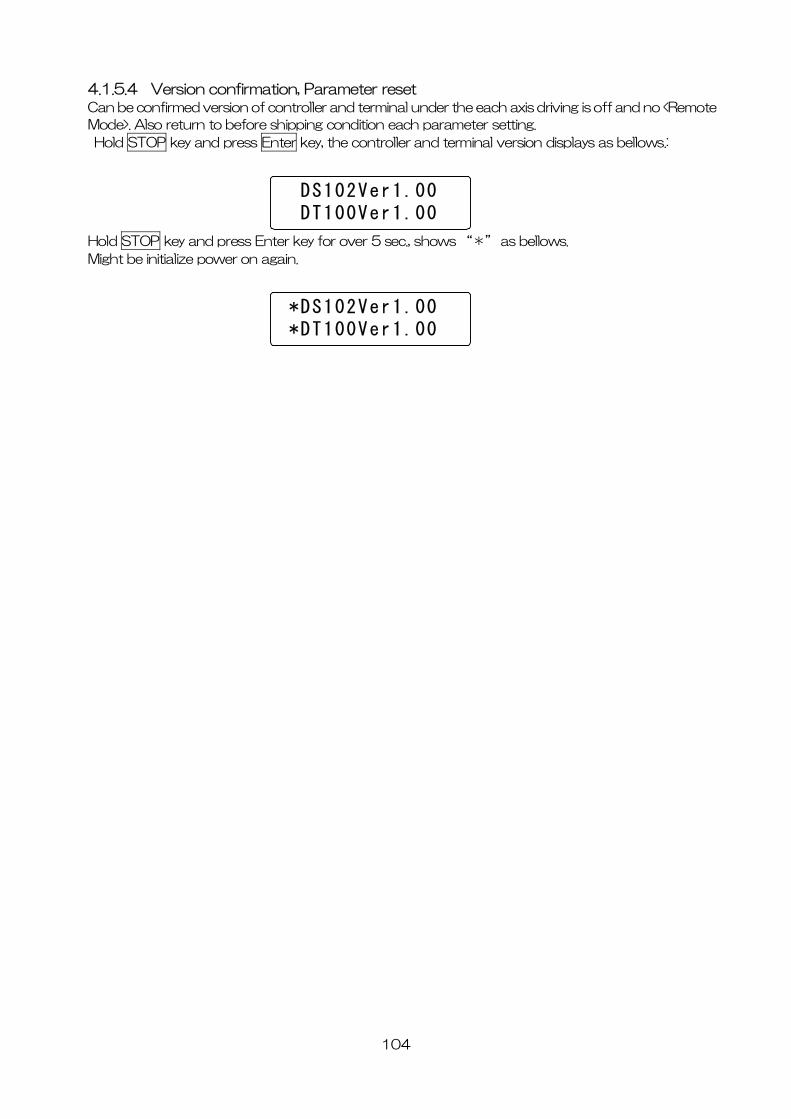
4.1.5.4 Version confirmation, Parameter reset Can be confirmed version of controller and terminal under the each axis driving is off and no <Remote
Mode>. Also return to before shipping condition each parameter setting.
Hold STOP key and press Enter key, the controller and terminal version displays as bellows.:
DS102Ver1.00 DT100Ver1.00
Hold STOP key and press Enter key for over 5 sec., shows “*” as bellows.
Might be initialize power on again.
*DS102Ver1.00 *DT100Ver1.00
104
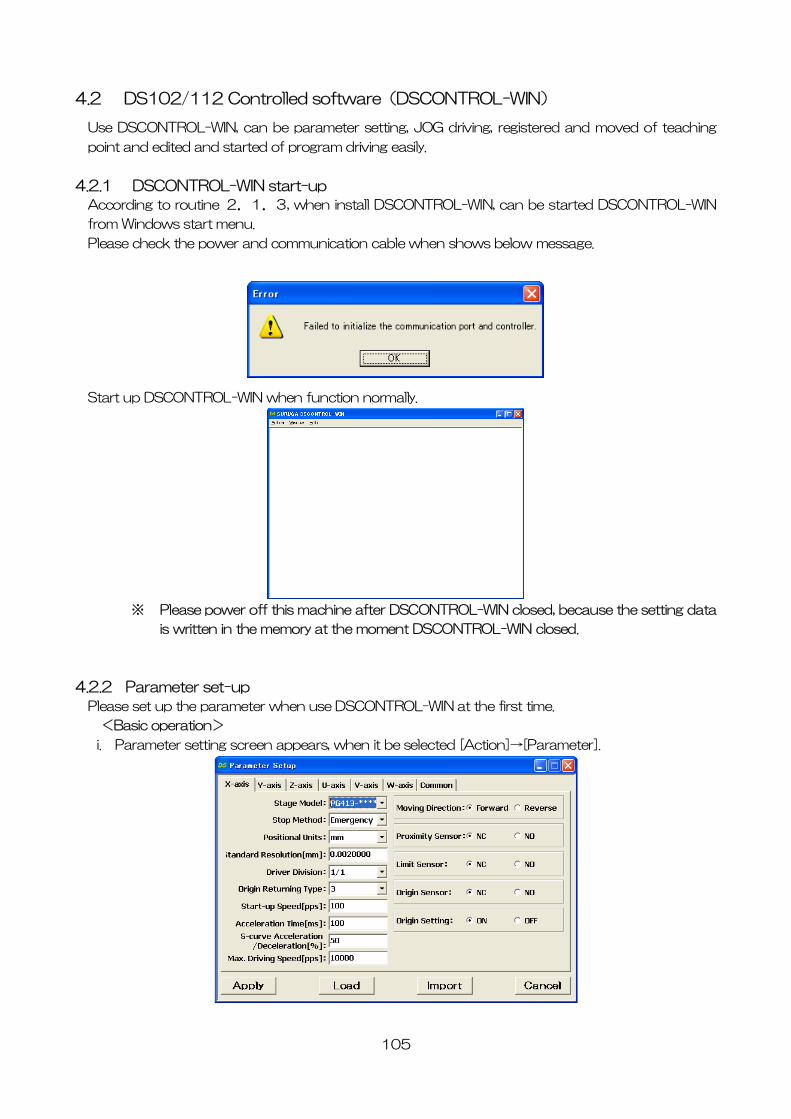
4.2 DS102/112 Controlled software(DSCONTROL-WIN)
Use DSCONTROL-WIN, can be parameter setting, JOG driving, registered and moved of teaching
point and edited and started of program driving easily.
4.2.1 DSCONTROL-WIN start-up
According to routine 2.1.3, when install DSCONTROL-WIN, can be started DSCONTROL-WIN
from Windows start menu.
Please check the power and communication cable when shows below message.
Start up DSCONTROL-WIN when function normally.
※ Please power off this machine after DSCONTROL-WIN closed, because the setting data
is written in the memory at the moment DSCONTROL-WIN closed.
4.2.2 Parameter set-up
Please set up the parameter when use DSCONTROL-WIN at the first time.
<Basic operation>
i. Parameter setting screen appears, when it be selected [Action]→[Parameter].
105
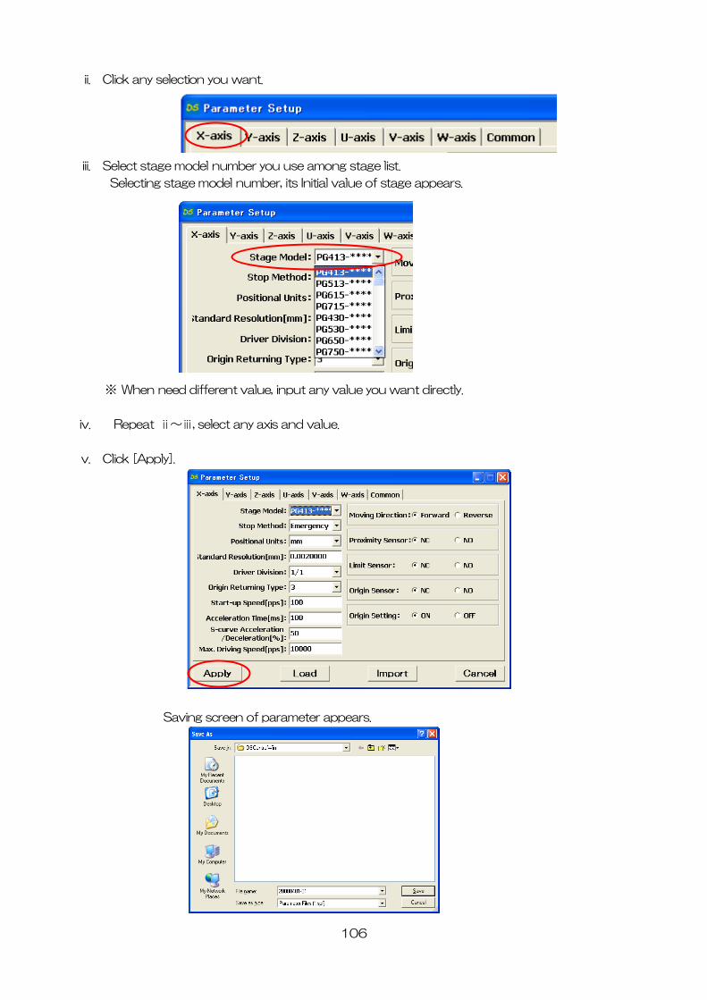
106
ii. Click any selection you want.
iii. Select stage model number you use among stage list.
Selecting stage model number, its Initial value of stage appears.
※ When n u want directly.
iv. Repeat ⅱ~ⅲ, select any axis and value.
v. Click [Apply].
eed different value, input any value yo
Saving screen of parameter appears.
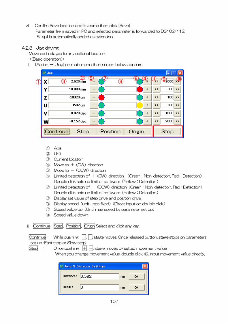
107
vi. Confi a
Param 02/112.
※ sp
.2.3 Jog driving
<Basic operation>
rn S ve location and its name then click [Save].
eter file is saved in PC and selected parameter is forwarded to DS1
f is automatically added as extension.
4
Move each stages to any optional location.
i. [Action]→[Jog] on main menu then screen below appears.
② ④ ⑤ ⑥ ⑦ ⑪ ③ ⑧ ⑨ ⑩
①
① Axis
② Unit
③ Current location
④ Move to +(CW)direction
⑤ Move to -(CCW)direction
⑥ Limited detection of +(CW)direction (Green:Non-detection, Red:Detection)
Double click sets up limit of software(Yellow:Detec n)
⑦ Lim ed detection of -(CCW)direction(Green:Non-detection, Red : Detection)
n drive
⑨ Dis lay speed(unit:pps fixed)(Direct input on double click)
eter set up)
Speed value down
ii. Contin ny key.
tio
it
Double click sets up limit of software(Yellow:Detection)
⑧ Display set value of step drive and positio
p
⑩ Speed value up(Until max speed by param
⑪
ue、Step、Position、Origin Select and click a
Continue: While pushing +, -, stage moves. Once released button, stage stops on parameters
set up (Fast stop or Slow stop).
Step : Once pushing +, -, stage moves by setted movement value.
When you change movement value, double click ⑧, input movement value directly.
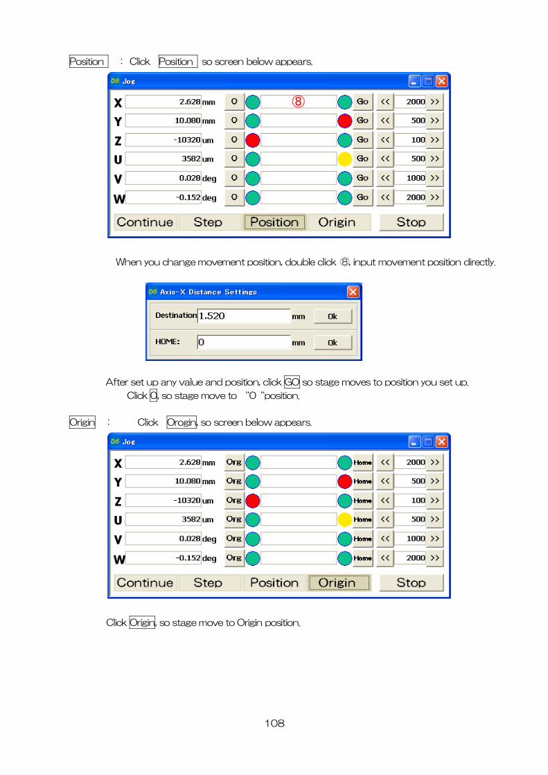
108
Position : Click Position so screen below appears.
ange movement position, double click ⑧, input movement position directly. When you ch
After set up any value and position, click GO so stage moves to position you set up.
Click 0, so stage move to “0“position.
Origin : Click Orogin, so screen below appears.
Click Origin, so stage move to Origin position.
⑧
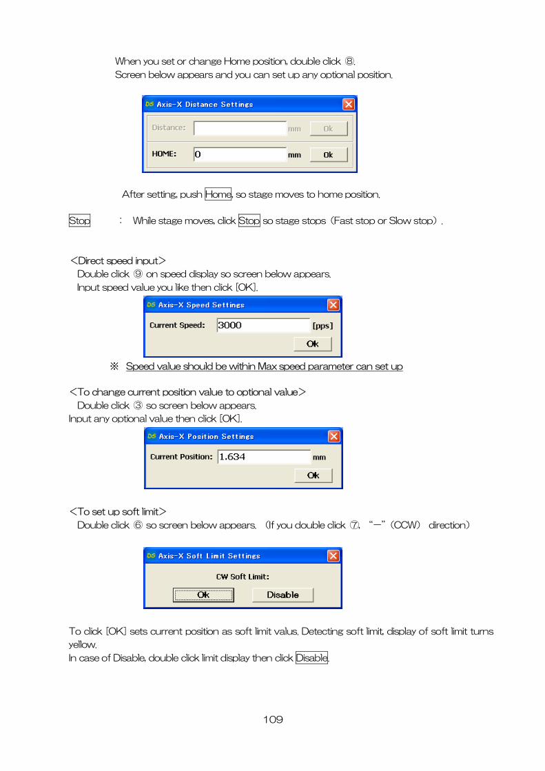
109
you set or change Home position, double click ⑧.
low appears and you can set up any optional position.
When
Screen be
After setting, push Home, so stage moves to home position.
Stop : While stage moves, click Stop so stage stops(Fast stop or Slow stop).
<Direct speed input>
Double click ⑨ on speed display so screen below appears.
Input speed value you like then click [OK].
※ Speed value should be within Max speed parameter can set up
<To cha osition value to optional value>
b
nge current p
Dou le click ③ so screen below appears.
Input any optional value then click [OK].
<To set up soft limit>
le click ⑦, “-”(CCW) direction)
Double click ⑥ so screen below appears. (If you doub
T click [OK] sets current position as soft limit valus. Detecting o soft limit, display of soft limit turns
yellow.
In case of Disable, double click limit display then click Disable.
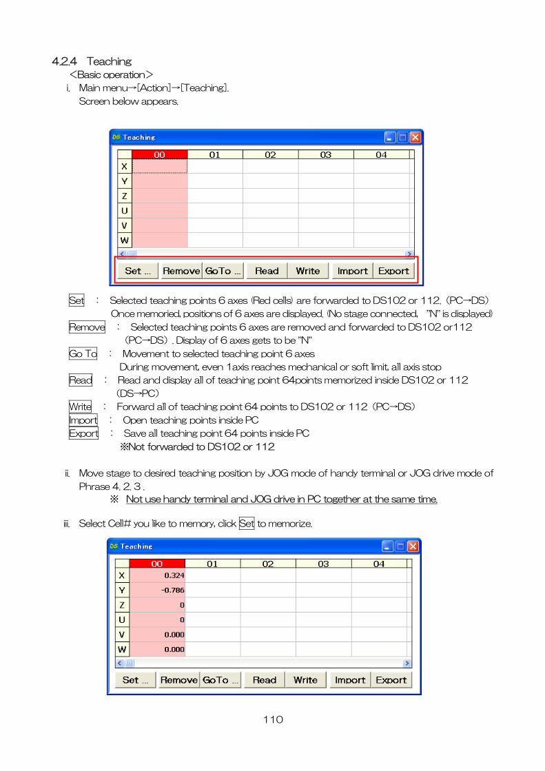
110
4. .4 Teaching
<Basic operation>
i. Main menu→[Action]→[Teaching].
Screen below appears.
2
Set : Selected teaching points 6 axes (Red cells) are forwarded to DS102 or 112.(PC→DS)
Once memoried, positions of 6 axes are displayed. (No stage connected, ”N” is displayed)
Remove : Selected teaching points 6 axes are removed and forwarded to DS102 or112
(PC→DS). Display of 6 axes gets to be ”N” Go To : Movement to selected teaching point 6 axes
During movement, even 1axis reaches mechanical or soft limit, all axis stop
Read : Read and display all of teaching point 64points memorized inside DS102 or 112
(DS→PC)
Write : Forward all of teaching point 64 points to DS102 or 112(PC→DS)
Import : Open teaching points inside PC
Export : Save all teaching point 64 points inside PC
※Not forwarded to DS102 or 112
ii. Move stage to desired teaching position by JOG mode of handy terminal or JOG drive mode of
Phrase 4. 2. 3 .
※ Not use handy terminal and JOG drive in PC together at the same time.
iii. Select Cell# you like to memory, click Set to memorize.

111
morize point you need. iv. Repeat ⅱ~ⅲ to me
v. Select memorized teaching Cell# then push Go to and make sure memorized position is correct.
vi. If memorized position is correct, click Set to save 64 teaching points in PC.
ching points memorized in DS102 or 112>
ed 64 teaching points inside DS.
<How to back up tea
i. Click Read to read and display memoriz
ii. Click Export to forward displayed 64 teaching points to PC.
<To forward Teching points memorized in PC to DS102 or 112>
i. Click Import to import and display teaching points memorized inside PC.
ii. Click Write to write 64 teaching points to DS102 or 112.
※ Convenient for forwarding all same teaching points to several DS.
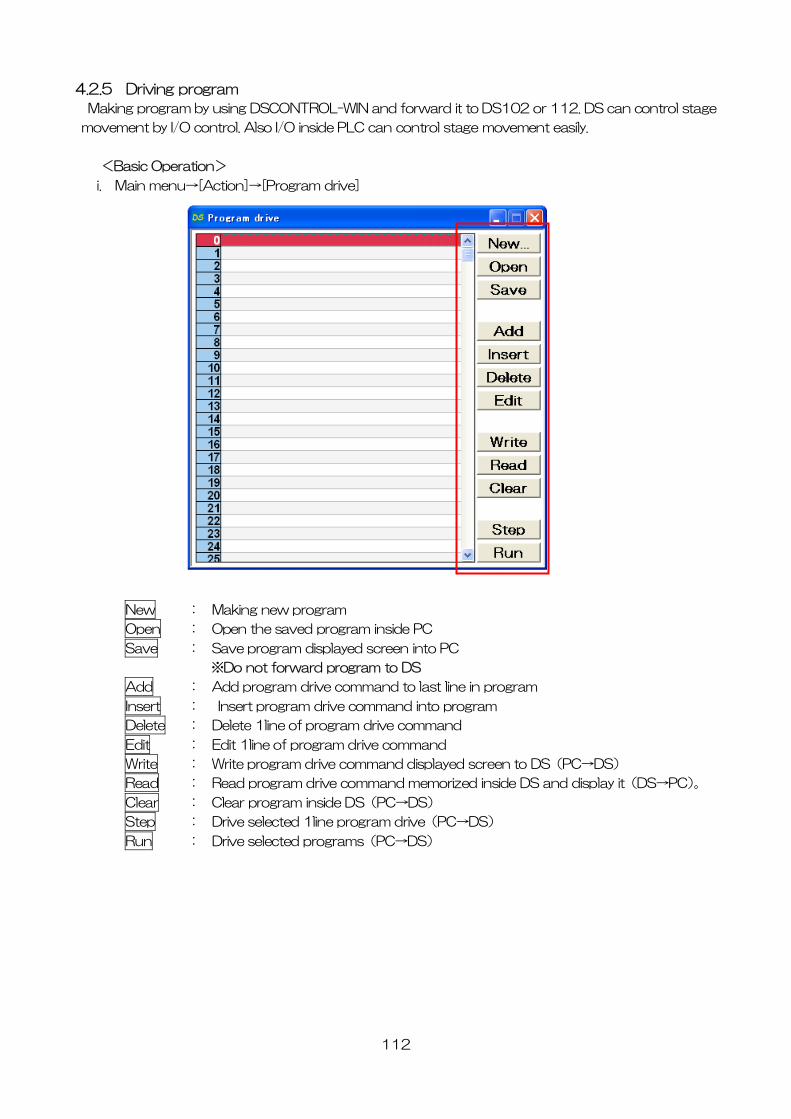
112
4.2
Making program by using DSCONT OL-WIN and forward it to DS102 or 112. DS can control stage
mov ement easily.
>
i. M
.5 Driving program
R
ement by I/O control. Also I/O inside PLC can control stage mov
<Basic Operation
ain menu→[Action]→[Program drive]
New : Making new program
Open : Open the saved program inside PC
Save : Save program displayed screen into PC
※Do not forward program to DS
Add : Add program drive command to last line in program
Insert : Insert program drive command into program
Delete : Delete 1line of program drive command
Edit : Edit 1line of program drive command
Write : Write program drive command displayed screen to DS(PC→DS)
Read : Read program drive command memorized inside DS and display it(DS→PC)。
Clear : Clear program inside DS(PC→DS)
Step : Drive selected 1line program drive(PC→DS)
Run : Drive selected programs(PC→DS)
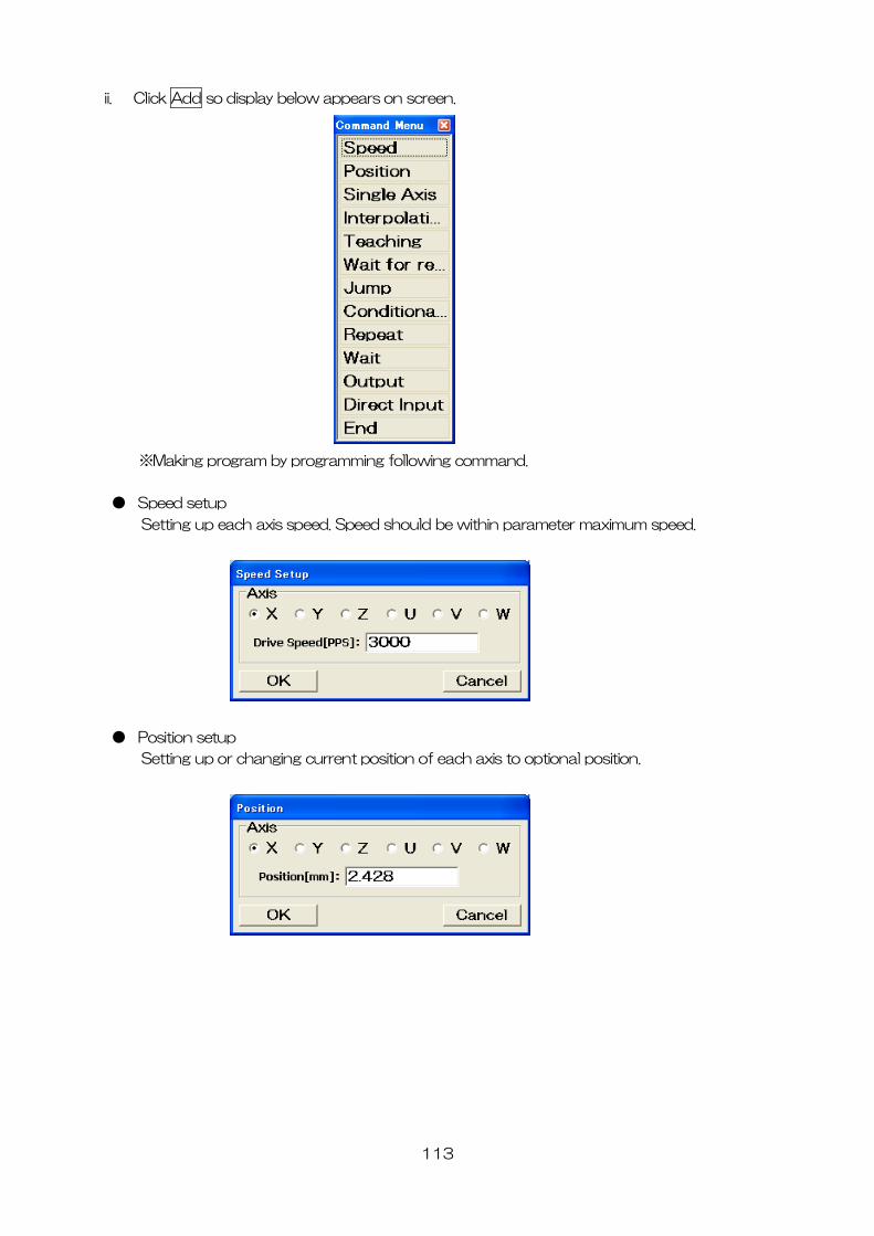
113
ii lay below appears on screen. . Click Add so disp
● Speed setup
is speed. Speed should be within parameter maximum speed.
※Making program by programming following command.
Setting up each ax
●
Setting up or hanging current position of each axis to optional position.
Position setup
c
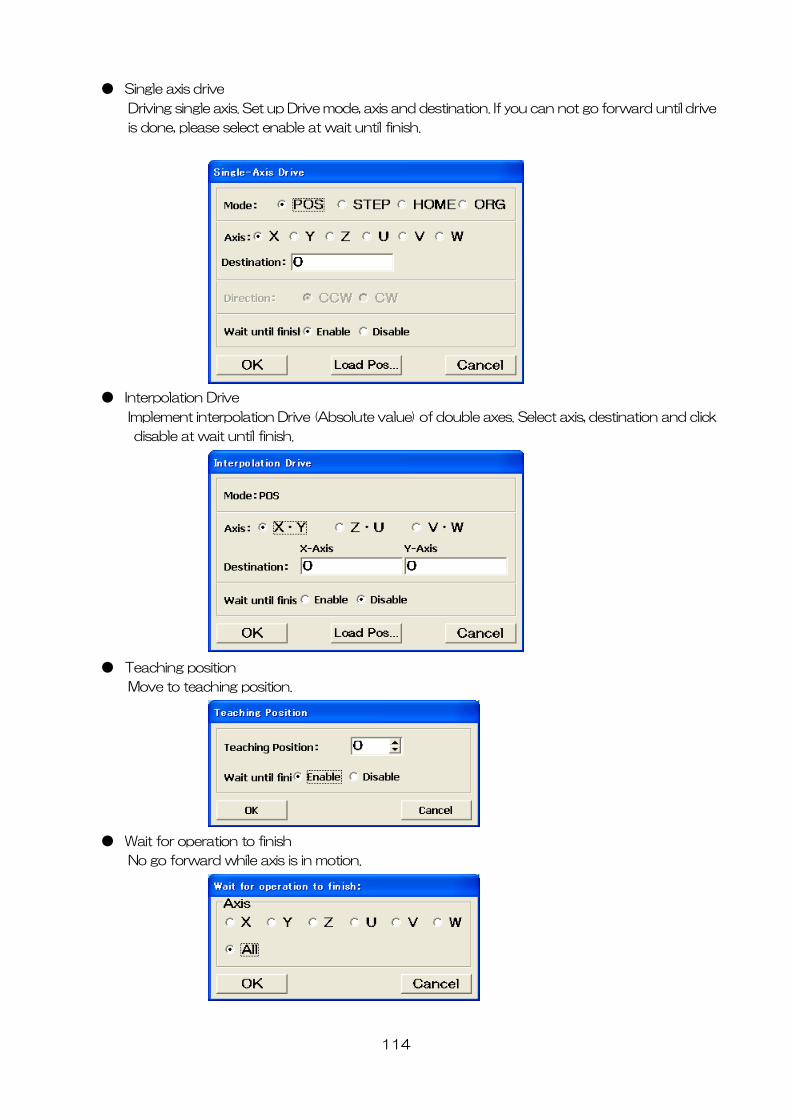
114
● Single axis drive
Driving single axis. Set up Drive mode, axis and destination. If you can not go forward until drive
is done, please select enable at wait until finish.
● Interpolation Drive
Implement interpolation Drive (Absolute value) of double xes. Select axis, destination and click
isable at wait until finish.
a
d
● Teaching position
Move to teaching position.
● Wait for operation to finish
No go forward while axis is in motion.
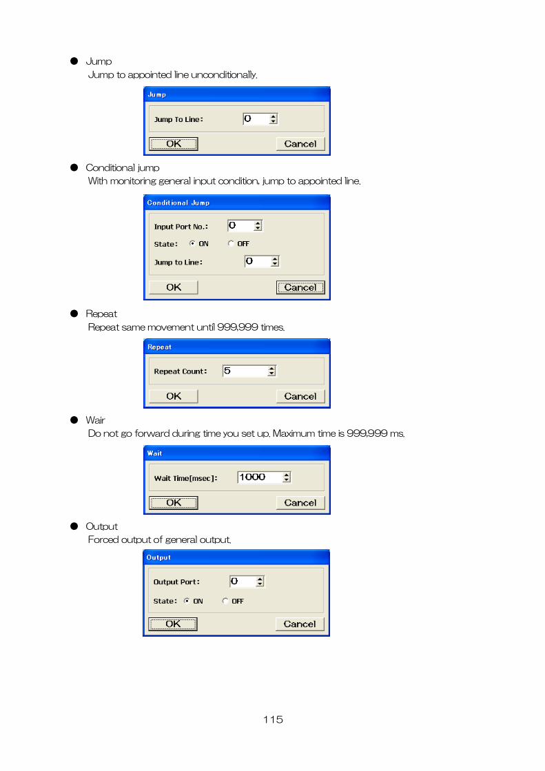
115
● Jump
Jump to appointed line unconditionally.
● Conditional jump
With monitoring general input condition, jump to appointed line.
● Repeat
Repeat same movement until 999,999 times.
● Wair
Do not go forward during time you set up. Maximum time is 999,999 ms.
● Output
Forced output of general output.
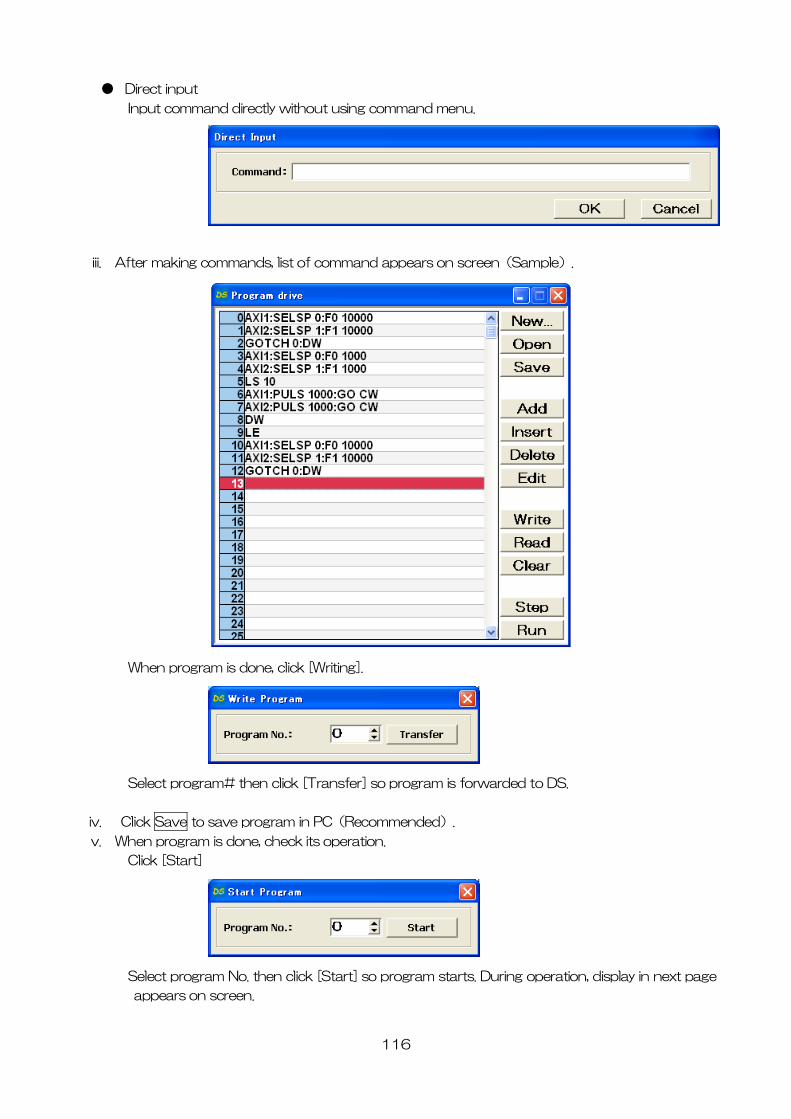
● Direct input
Input command directly without using command menu.
iii. After making commands, list of command appears on screen(Sample).
When program is done, click [Writing].
Select program# then click [Transfer] so program is forwarded to DS.
iv. Click Save to save program in PC(Recommended).
v. When program is done, check its operation.
Click [Start]
Select program No. then click [Start] so program starts. During operation, display in next page
appears on screen.
116
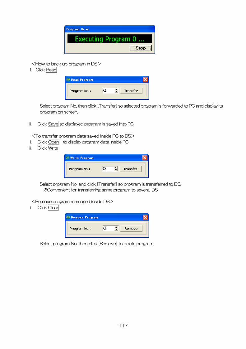
<How to back up program in DS>
i. Click Read
Selec rogram No. then click [Transfer] so selected program is forwarded to PC and display its
program on screen.
ii. C
t p
lick Save so displayed program is saved into PC.
<To transfer a sav e PC to DS>
i. Click Open to play program ta insid
program dat ed insid
dis da e PC.
ii. Click Write
Select program No. and click [Transfer] so program is transferred to DS.
※Con nsfe am to several DS.
<Remove p memoried i >
i. Click Clea
venient for tra rring same progr
rogram nside DS
r
Select program No. then click [Remove] to delete program.
117
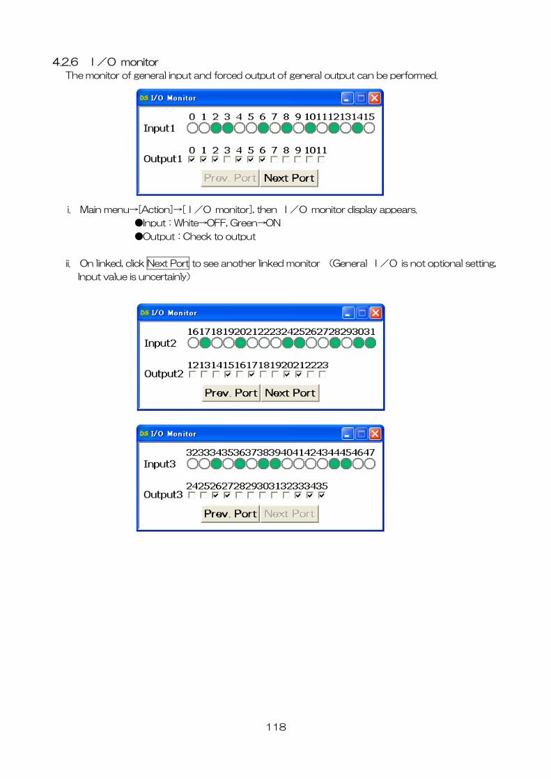
118
monitor 4.2.6 I/O
The monitor of general input and forced output of general output can be performed.
i. Main menu→[A n]→[I/O m r], then I/O monitor display appears.
●I :White→OFF, reen→ON
● put:Check t
to see another linked monitor (General I/O is not optional setting,
ctio onito
nput G
Out to outpu
ii. On linked, click Next Port
Input value is uncertainly)
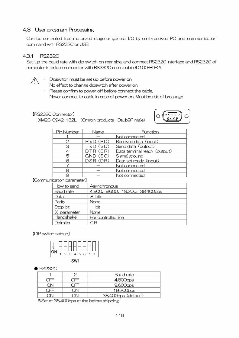
119
4.3 User prog ssing
Can be controlled torized eived PC and communication
co and with RS232C or USB.
4.3.
S up the baud rate with dip switch on rear side, and connect RS232C interface and RS232C of
co oss cable (D100-R9-2).
Please confirm to power off before connect the cable.
Never connect to cable in case of power on. Must be risk of breakage
C Connector】
XM2C-0942 2L (Omron products:Dsub9P male)
Pin Number Nam
ram Proce
free mo stage or general I/O by sent/rec
mm
1 RS232C
et-
mputer interface connector with RS232C cr
・ Dipswitch must be set up before power on.
No effect to change dipswitch after power on.
・
【RS232
-13
e Function1 - Not connected2 RxD(RD) Received data(input)3 TxD(SD) Send data(output)4 DTR(ER) Data terminal ready(output) 5 GND(SG) Siignal ground6 DSR(DR) Data set ready(input)7 - Not connected8 - Not connected9 - Not connected
【Communication parameter】
How to send Asynchronous
Baud rate 4,800、9,600、19,200、38,400bps
Data 8 bits
Parity None
Stop bit 1 bit
X parameter None Handshake For controlled line
Delimiter CR
【DIP switch set-up】
● RS23
1 2 3 4 5 6 ON
7 8
SW1
2C
1 2 Baud rate
OFF OFF 4,800bps
ON OFF 9,60 ps 0b
OFF ON 19,2 bps 00
ON ON 38,400bp default) s(
※Set at 38,400bps at the before shipping.
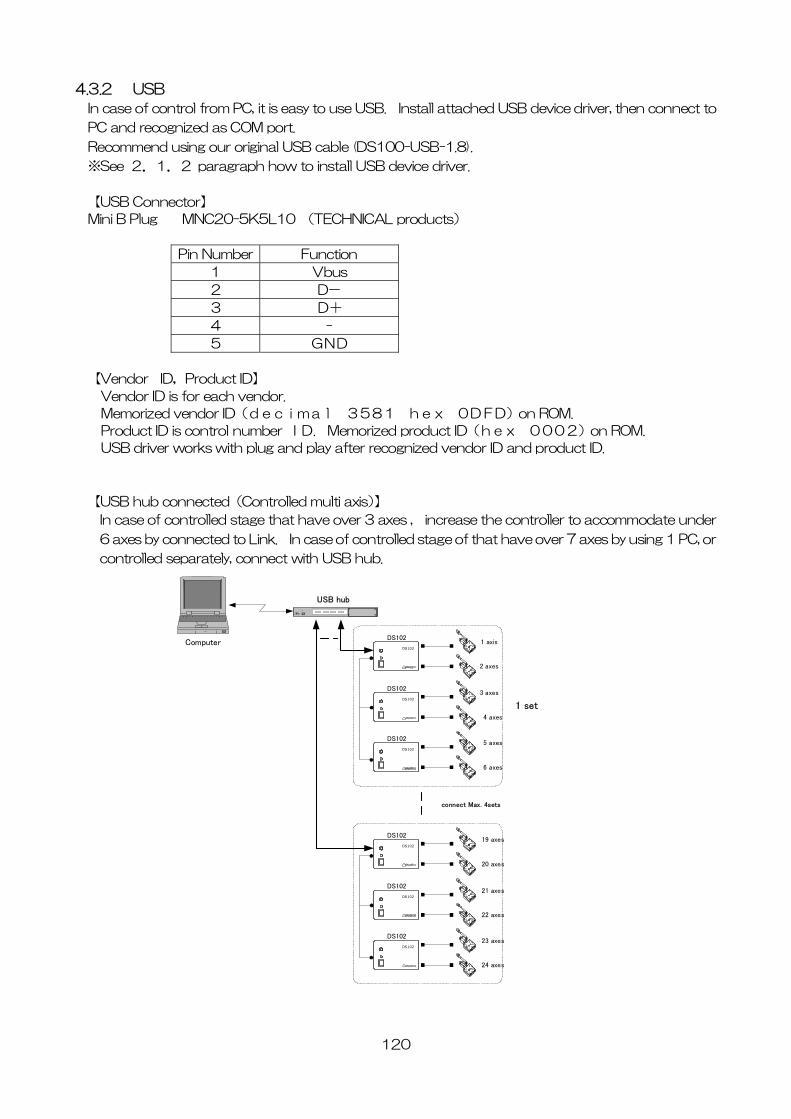
4.3.2 USB
120
In , then connect to
C and recognized as COM port.
Recommend using our or cable (DS100-US
※See 2.1.2 w to install USB device driver.
【USB C nnector】
Mini B Plug
case of control from PC, it is easy to use USB. Install attached USB device driver
P
iginal USB B-1.8).
paragraph ho
o
MNC20-5K5L10 (TECHNICAL products)
Pin Number Function
1 Vbus
2 D-
3 D+
4 -
5 GND
【Vendor ID,Product ID】
Vendor ID is for each vendor.
Memorized vendor ID(decimal 3581 hex 0DFD)on ROM.
Product ID is control number ID. Memorized product ID(hex 0002)on ROM.
USB driver works with plug and play after recognized vendor ID and product ID.
【USB hub connected(Controlled multi axis)】
In case of controlled stage that have over 3 axes , increase the controller to accommodate under
6 axes by connected to Link. In case of controlled stage of that have over 7 axes by using 1 PC, or
controlled separately, connect with USB hub.
A
C
USBハブ
Computer
1 set
connect Max. 4sets
1 axis
2 axes
DS102
DS102
3 axes
4 axes
DS102
DS102
5 axes
6 axes
DS102
DS102
USB hub
19 axes
20 axes
DS102
DS102
21 axes
22 axes
DS102
DS102
23 axes
24 axes
DS102
DS102
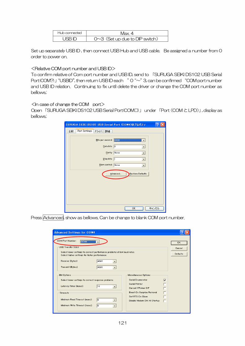
121
Hub connected Max. 4
USB ID 0~3(Set up due to DIP switch)
Set up SB ID , then connect USB Hub and USB cable. Be assigned a number from 0
order
<R um
To om
Port , the M port number
and USB ID relation. Continuing to fix until delete the driver or change the COM port number as
ello
I
p Port(COM と LPD)」, display as
e
separately U
to power on.
elative COM port n ber and USB ID>
confirm relative of C port number and USB ID, send to 「SURUGA SEIKI DS102 USB Serial
(COM?)」“USBID” n return USB ID each ”0“~”3, can be confirmed “CO
b ws.:
<n case of change the COM port>
O en 「SURUGA SEIKI DS102 USB Serial Port(COM□)」 under 「
b llows.:
Press Advanced, show a change to blank COM port number.
s bellows. Can be
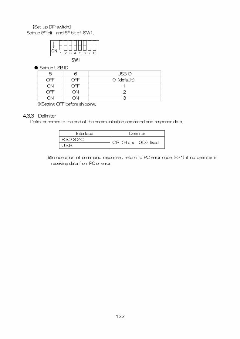
122
【Set-up DIP switch】
Set-up 5th nd 6th bit of SW
● Set-up USB ID
6 USB ID
bit a 1.
5
1 2 3 4 5 6 ON
7 8
SW1
OFF OF 0(default) F
ON OF 1 F
OFF O 2 N
ON O 3 N
※Setting OFF before
4.3 limiter
es to the end of the communica d response d
shipping.
.3 De
Delimiter com tion command an ata.
Interface Delimiter
RS232C
USB 0D)fixed CR(Hex
※In operation pon return to PC error de (E21) if no delimiter
receiving dat rror.
of command res se , co in
a from PC or e
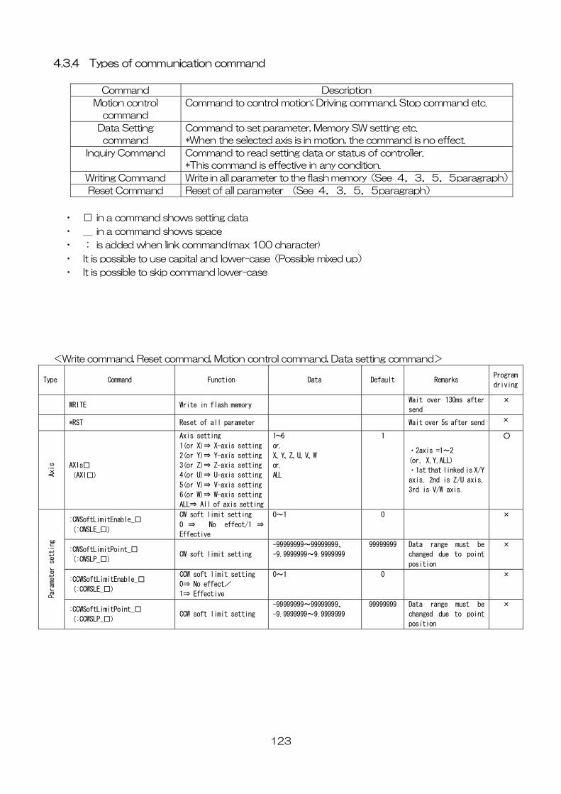
123
4.3.4 Types of communication command
Command Description
Motion control
command
trol motion; Driving command, Stop command etc. Command to con
Data Setting
command
arameter, Memory SW setting etc.
d axis is in motion, the command is no effect.
Command to set p
*When the selecte
Inquiry Command setting data or status of controller.
effective in any condition.
Command to read
*This command is
Writing Command ter to the flash memory(See 4.3.5.5paragraph)Write in all parame
Reset Command eter (See 4.3.5.5paragraph) Reset of all param
・ □ in a command sho
・ _ in a command sho
・ : is added when link acter)
・ to use ca lower-case(Possible mixed up)
・ It is possible to skip co er-case
<W d, Reset com otion control command, Data setting com and>
Type
Command ion Data Default Remarks Program
dri
ws setting data
ws space
command(max 100
pital and
char
It is possible
mmand low
rite comman mand, M m
Functving
Wait over 130ms after
nd
× WRITE Write in flash memory
se
*RST all parameter Wait over 5s after send × Reset of
Axis
(AXI□)
etting
axis setting
xis setting
5(or V)⇒ V-axis setting
6(or W)⇒ W-axis setting
ALL⇒ All of axis setting
or,
X、Y、Z、U、V、W
or,
ALL
2axis =1~2
, X,Y,ALL)
・1st that linked is X/Y
axis, 2nd is Z/U axis,
3rd is V/W axis.
AXIs□
Axis setting
1(or X)⇒ X-axis setting
2(or Y)⇒ Y-axis s
3(or Z)⇒ Z-
4(or U)⇒ U-a
1~6 1
・
(or
○
:CWSoftLimitEnable_□
(:CWSLE_□)
CW soft limit setting
0 ⇒ No effect/1 ⇒
Effective
0~1 0
×
:CWSoftLimitPoint_□
CW soft limit setting
-99999999~99999999、
-9.9999999~9.9999999
99999999 Data range must be
changed due to point
position
×
(:CWSLP_□)
:CCWSoftLimitEnable_□
(:CCWSLE_□)
CCW soft limit setting
0⇒ No effect/
1⇒ Effective
0~1 0 ×
Parameter setting
tPoint_□
(:CCWSLP_□) CCW soft limit setting
-99999999~99999999、
-9.9999999~9.9999999
99999999 Data range must be
changed due to point
position
× :CCWSoftLimi
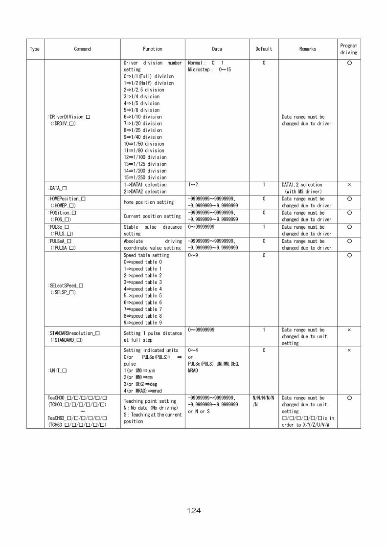
124
Type Command Function
Data Default Remarks Program
driving
:DRiverDIVision_□
division
0, 1
Microstep: 0~15
ta range must be
changed due to driver(:DRDIV_□)
Driver division number
setting
0⇒1/1(Full) division
1⇒1/2(Half) division
2⇒1/2.5 division
3⇒1/4 division
4⇒1/5 division
5⇒1/8 division
6⇒1/10 division
7⇒1/20 division
8⇒1/25 division
9⇒1/40 division
10⇒1/50 division
11⇒1/80 division
12⇒1/100 division
13⇒1/125 division
14⇒1/200
15⇒1/250 division
Normal: 0
Da
○
:DATA_□ 1⇒DATA1 selection 1~2 1 DATA1,2 selection
with MS driver)
×
2⇒DATA2 selection (
:HOMEPosition_□
-99999999~99999999、
9.9999999
0 Data range must be
anged due to driver
○
(:HOMEP_□)Home position setting
-9.9999999~ ch
:POSition_□
setting
-99999999~99999999、
9~9.9999999
0 Data range must be
changed due to driver
○
(:POS_□)Current position
-9.999999
:PULSe_□
(:PULS_□)
nce 0~99999999 1 ta range must be
changed due to driver
○ Stable pulse dista
setting
Da
:PULSeA_□
(:PULSA_□)
etting
99999999、
-9.9999999~9.9999999
ta range must be
changed due to driver
Absolute driving
coordinate value s
-99999999~ 0 Da ○
:SELectSPeed_□
(:SELSP_□)
Speed table setting
0⇒speed table 0
1⇒speed table 1
2⇒speed table 2
3⇒speed table 3
4⇒speed table 4
5⇒speed table 5
6⇒speed table 6
7⇒speed table 7
8⇒speed table 8
9⇒speed table 9
0~9 0
○
:STANDARDresolutio
(:STANDARD_□
n_□
)
a range must be
nged due to unit
setting
Setting 1 pulse distance
at full step
0~99999999 1 Dat
cha
×
:UNIT_□
Setting indicated unit
0(or PULSe(PULS)) ⇒
s
m
0~4
or
LS),UM,MM,DEG,
MRAD
0 ×
pulse
1(or UM)⇒μ
2(or MM)⇒mm
3(or DEG)⇒deg
4(or MRAD)⇒mrad
PULSe(PU
TeaCH00_□/□/□/□/□/□
(TCH00_□/□/□/□/□/□)
~
/□/□/□/□
/□/□/□/□)
iving)
ent
-99999999~99999999、
9~9.9999999
or N or S
N/N/N/N/N
/N
ta range must be
changed due to unit
tting
□/□/□/□/□is in
order to X/Y/Z/U/V/W
○
TeaCH63_□/□
(TCH63_□/□
Teaching point setting
N:No data(No dr
S:Teaching at the curr
position
-9.999999
Da
se
□/
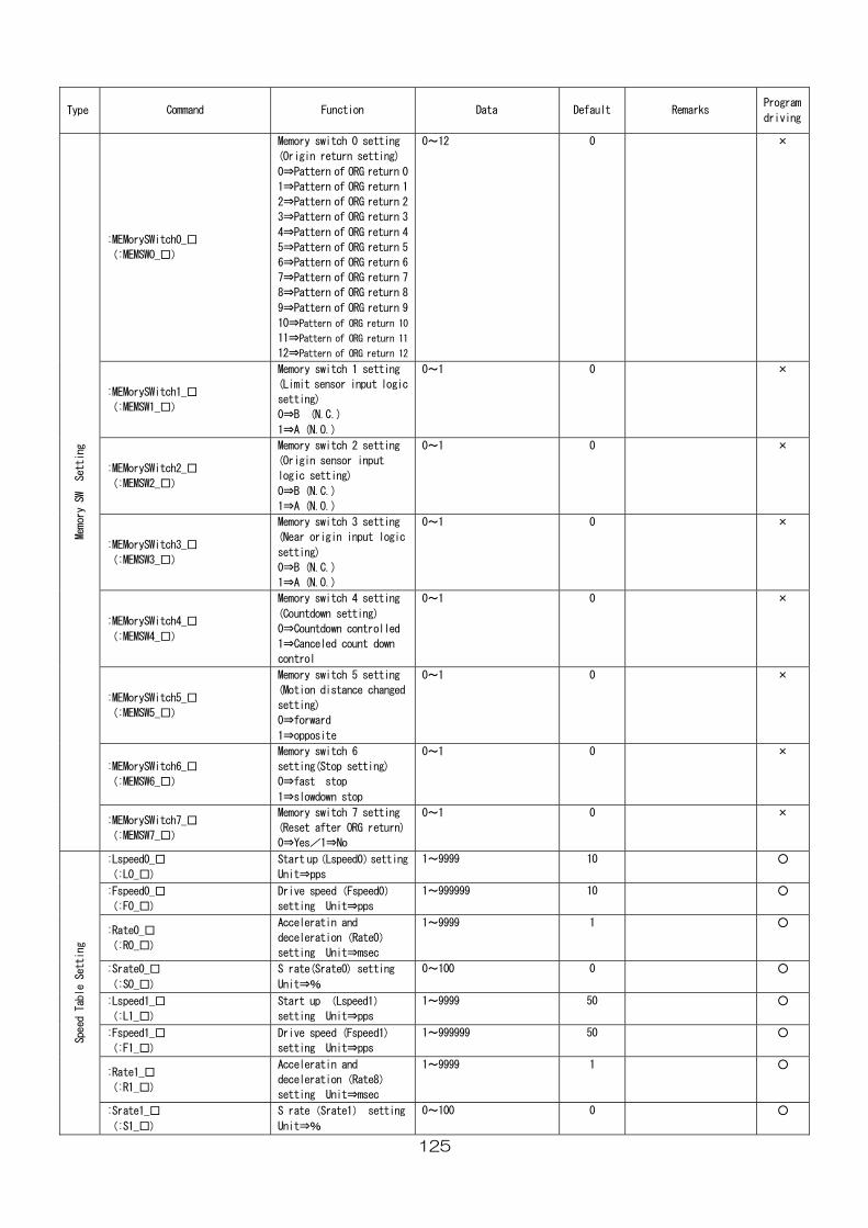
125
Type
Command Function Data Default Remarks Program
driving
:MEMorySWitch0_□
)
)
0
n 1
return 2
n 3
of ORG return 6
ern of ORG return 7
9
of ORG return 10
turn 11
return 12
(:MEMSW0_□
Memory switch 0 setting
(Origin return setting
0⇒Pattern of ORG return
1⇒Pattern of ORG retur
2⇒Pattern of ORG
3⇒Pattern of ORG retur
4⇒Pattern of ORG return 4
5⇒Pattern of ORG return 5
6⇒Pattern
7⇒Patt
8⇒Pattern of ORG return 8
9⇒Pattern of ORG return
10⇒Pattern
11⇒Pattern of ORG re
12⇒Pattern of ORG
0~12 0 ×
:MEMorySWitch1_□
(:MEMSW1_□)
h 1 setting
ic
0~1 0
× Memory switc
(Limit sensor input log
setting)
0⇒B (N.C.)
1⇒A (N.O.)
:MEMorySWitch2_□
(:MEMSW2_□)
or input
0⇒B (N.C.)
0~1 0
× Memory switch 2 setting
(Origin sens
logic setting)
1⇒A (N.O.)
:MEMorySWitch3_□
)
Memory switch 3 setting
gic
)
0~1 0 ×
(:MEMSW3_□
(Near origin input lo
setting
0⇒B (N.C.)
1⇒A (N.O.)
:MEMorySWitch4_□
(:MEMSW4_□)
ing
led
down
0
× Memory switch 4 sett
(Countdown setting)
0⇒Countdown control
1⇒Canceled count
control
0~1
:MEMorySWitch5_□
(:MEMSW5_□)
etting
nged
0
× Memory switch 5 s
(Motion distance cha
setting)
0⇒forward
1⇒opposite
0~1
:MEMorySWitch6_□
(:MEMSW6_□)
Memory switch 6
setting(Stop setting)
0⇒fast stop
1⇒slowdown stop
0~1 0
×
Memory SW Setting
tch7_□
(:MEMSW7_□)
tting 0
×
:MEMorySWiMemory switch 7 se
(Reset after ORG return)
0⇒Yes/1⇒No
0~1
:Lspeed0_□
(:L0_□)
setting
it⇒pps
1Start up(Lspeed0)
Un
1~9999 0
○
:Fspeed0_□
(:F0_□)
Drive speed(Fspeed0)
setting Unit⇒pps
1~999999 10 ○
:Rate0_□
(:R0_□) celeration(Rate0)
setting Unit⇒msec
1~9999 1
○ Acceleratin and
de
:Srate0_□
(:S0_□)
S rate(Srate0) setting
Unit⇒%
0~100 0
○
:Lspeed1_□
(:L1_□)
Start up (Lspeed1)
setting Unit⇒pps
1~9999 50
○
:Fspeed1_□
(:F1_□)
Drive speed (Fspeed1)
setting Unit⇒pps
1~999999 50
○
:Rate1_□
(:R1_□)
Acceleratin and
deceleration(Rate8)
setting Unit⇒msec
1~9999 1
○
Speed Table Setting
:Srate1_□
(:S1_□)
S rate(Srate1) setting
Unit⇒%
0~100 0
○
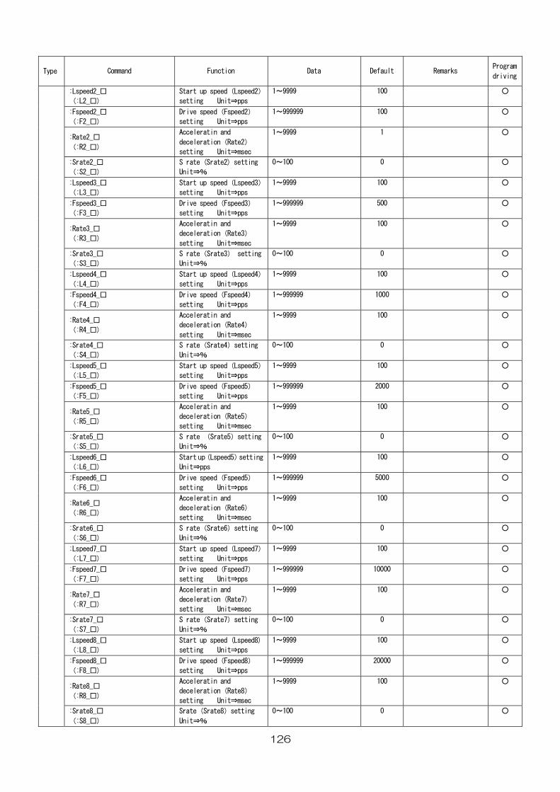
126
Type
Command Function Data Default Remarks Program
driving
:Lspeed2_□
(:L2_□)
1 Start up speed(Lspeed2)
setting Unit⇒pps
1~9999 00
○
:Fspeed2_□
(:F2_□) ⇒pps
1~999999 100 ○ Drive speed(Fspeed2)
setting Unit
:Rate2_□
(:R2_□) on(Rate2)
1~9999 1
○ Acceleratin and
decelerati
setting Unit⇒msec
:Srate2_□
(:S2_□)
rate2) setting 0~100 0
○ S rate (S
Unit⇒%
:Lspeed3_□
(:L3_□)
1~9999 100
○ Start up speed(Lspeed3)
setting Unit⇒pps
:Fspeed3_□
1~999999 500
○
(:F3_□)
Dri d(Fspeed3)
setting Unit⇒pps
ve spee
:Rate3_□
(:R3_□)
1~9999 100
○ Acceleratin and
deceleration(Rate3)
ting set Unit⇒msec
:Srate3_□
(:S3_□)
ate3) setting 0~100 0
○ S rate(Sr
Unit⇒%
:Lspeed4_□
(:L4_□)
speed(Lspeed4) 1~9999 100
○ Start up
setting Unit⇒pps
:Fspeed4_□
(:F4_□)
d(Fspeed4) 1~999999 1000
○ Drive spee
setting Unit⇒pps
:Rate4_□
(:R4_□)
in and
Unit⇒msec
1~9999 100
○ Accelerat
deceleration(Rate4)
setting
:Srate4_□
(:S4_□)
S rate(Srate4)setting
Unit⇒%
0~100 0
○
:Lspeed5_□ (Lspeed5) 1~9999 100 ○
(:L5_□)
Start up speed
setting Unit⇒pps
:Fspeed5_□
(:F5_□)
1~999999 2000
○ Drive speed(Fspeed5)
setting Unit⇒pps
:Rate5_□
(:R5_□)
1~9999 100
○ Acceleratin and
deceleration(Rate5)
setting Unit⇒msec
:Srate5_□
(:S5_□)
S rate (Srate5)setting
Unit⇒%
0~100 0
○
:Lspeed6_□
(:L6_□)
Start up(Lspeed5)setting
Unit⇒pps
1~9999 100
○
:Fspeed6_□
(:F6_□)
Drive speed(Fspeed5)
setting Unit⇒pps
1~999999 5000
○
:Rate6_□
(:R6_□)
Acceleratin and
deceleration(Rate6)
setting Unit⇒msec
1~9999 100
○
:Srate6_□
(:S6_□)
S rate(Srate6)setting
Unit⇒%
0~100 0
○
:Lspeed7_□
(:L7_□)
Start up speed(Lspeed7)
setting Unit⇒pps
1~9999 100
○
:Fspeed7_□
(:F7_□)
Drive speed(Fspeed7)
setting Unit⇒pps
1~999999 10000
○
:Rate7_□
(:R7_□)
Acceleratin and
deceleration(Rate7)
setting Unit⇒msec
1~9999 100
○
:Srate7_□
(:S7_□)
S rate(Srate7)setting
Unit⇒%
0~100 0
○
:Lspeed8_□
(:L8_□)
Start up speed (Lspeed8)
setting Unit⇒pps
1~9999 100
○
:Fspeed8_□
(:F8_□)
Drive speed(Fspeed8)
setting Unit⇒pps
1~999999 20000
○
:Rate8_□
(:R8_□)
Acceleratin and
deceleration(Rate8)
setting Unit⇒msec
1~9999 100
○
:Srate8_□
(:S8_□)
Srate(Srate8)setting
Unit⇒%
0~100 0
○
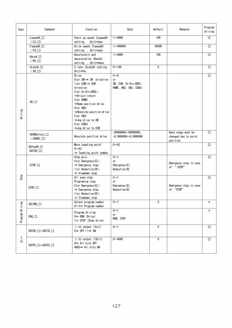
127
Fu Dat RemaProgram
drivingType Command nction a Default rks
:Lspeed9_□
(:L9_□)
Start up speed(Lspeed9)
setting Unit⇒pps
1~9999 100
○
:Fspeed9_□
(:F9_□)
Drive speed(Fspeed9)
setting Unit⇒pps
1~999999 00
500 ○
:Rate9_□
(:R9_□)
Acceleratin and 1~9999
deceleration(Rate9)
setting Unit⇒msec
100
○
:Srate9_□
(:S9_□)
S rate(Srate9)setting 0~100 0
○
Unit⇒%
:GO_□
Drive
0(or CW)⇒ CW direction
G))
ive
tion drive
0~6
or
CW, CCW, OriGin(ORG),
HOME, ABS, CWJ, CCWJ)
○
1(or CCW)⇒ CCW
direction
2(or OriGin(OR
⇒Origin return
3(or HOME)
⇒Home position dr
4(or ABS)
⇒Absolute posi
5(or CWJ)
⇒Jog drive to CW
6(or CCWJ)
⇒Jog drive to CCW
:GOABSolute_□
(:GOABS_□) drive
-99999999~99999999、
-9.9999999~9.9999999
Data range must be
changed due to point
position
○
Absolute position
Driving
t
mber
0~63
○ GOTeaCH_□
(GOTCH_□)
Move teaching poin
0~63
⇒ Teaching point nu
:STOP_□
Stop axis
⇒ Emergency stop
⇒ Slowdown stop
0~1
or
Emergency
Reduction
E e
o
○
0(or Emergency(E))
1(or Reduction(R))
(E),
(R)
mergency stop in cas
f “:STOP”
S
Programing stop
p
1
or
Emergency
Reduction(R)
E
o
top
STOP_□
All axes stop 0~
0(or Emergency(E))
⇒ Emergency stop
1(or Reduction(R))
⇒ Slowdown sto
(E), mergency stop in case
f “STOP”
○
SELPRG_□ number
number
0~7 0
× Select program
0~7⇒ Program
Program Driving
drive)
0~1
or
RUN、STEP
×
PRG_□
Program driving
0⇒ RUN(Drive)
1⇒ STEP(Step
OUT00_□~OUT35_□
0~1 0
○ I/O output(1bit)
0⇒ OFF/1⇒ ON
I/
O
0⇒ All bits OFF
0
OUTP0_□~OUTP2_□
I/O output(12bit) 0~4095
4095⇒ All bits ON
○
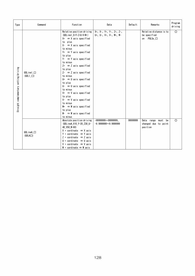
128
Type
Command Default Remarks Program
drivingFunction Data
GOLineI_□
(GOLI_□)
driving
+W-)
ified
ified
ified
ified
ied
ied
ecified
pecified
pecified
X+、X-、Y+、Y-、Z+、Z-、
U+、U-、V+、V-、W+、W-
Relative distance is to
be specified
on :PULSe_□
○ Relative position
(GOLineI_X+Y-Z+U-V
X+ ⇒ X axis spec
to plus
X- ⇒ X axis spec
to minus
Y+ ⇒ Y axis spec
to plus
Y- ⇒ Y axis spec
to minus
Z+ ⇒ Z axis specif
to plus
Z- ⇒ Z axis specif
to minus
U+ ⇒ U axis specified
to plus
U- ⇒ U axis sp
to minus
V+ ⇒ V axis specified
to plus
V- ⇒ V axis s
to minus
W+ ⇒ W axis specified
to plus
W- ⇒ W axis s
to minus
Str
riving
9、
9999999~9.9999999
99999999 Data range must be
c due to point
position
○
aight complementary setting/d
GOLineA_□
(GOLA□)
Absolute position driving -9
-9.(GOLineA_X10_Y-20_Z30_U-
40_V50_W-60)
X + cordinate ⇒ X axis
Y + cordinate ⇒ Y axis
Z + cordinate ⇒ Z axis
U + cordinate ⇒ U axis
⇒ V axisV + cordinate
W + cordinate ⇒ W axis
9999999~9999999
hanged
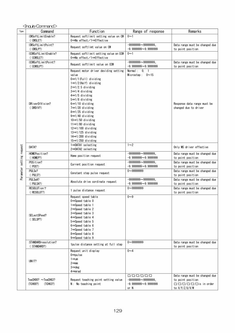
129
<Inquiry Command> Type ommand e of response Remarks C Function Rang
:CWSoftLimitEnable?
tting value on CW 0~1
(:CWSLE?)
Request softlimit se
0⇒No effect/1⇒Effective
:CWSoftLimitPoint?
(:CWSLP?) alue on CW
-99999999~99999999、
-9.9999999~9.9999999
ta range must be changed due
to point position Request softlimt v
Da
:CCWSoftLimitEnable?
)
Request softlimit setting value on CCW
0⇒No effect/1⇒Effective
0~1
(:CCWSLE?
:CCWSoftLimitPoint?
(:CCWSLP?) Request softlimit value on CCW
-99999999~99999999、
-9.9999999~9.9999999
Data range must be changed due
to point position
:DRiverDIVision?
(:DRDIV?)
Request motor driver deviding setting
value
0⇒1/1(Full) dividing
1⇒1/2(Half) dividing
2⇒1/2.5 dividing
3⇒1/4 dividing
4⇒1/5 dividing
5⇒1/8 dividing
6⇒1/10 dividing
7⇒1/20 dividing
8⇒1/25 dividing
9⇒1/40 dividing
10⇒1/50 dividing
11⇒1/80 dividing
12⇒1/100 dividing
13⇒1/125 dividing
14⇒1/200 dividing
15⇒1/250 dividing
Normal: 0, 1
Microstep: 0~15
Response data range must be
changed due to driver
:DATA? 1⇒DATA1 selecting
2⇒DATA2 selecting
1~2 Only MS driver effective
:HOMEPosition?
(:HOMEP?) Home position request
-99999999~99999999、
-9.9999999~9.9999999
Data range must be changed due
to point position
:POSition?
(:POS?) Current position request
-99999999~99999999、
-9.9999999~9.9999999
Data range must be changed due
to point position
:PULSe?
(:PULS?) Constant step pulse request
0~99999999 Data range must be changed due
to point position
:PULSeA?
(:PULSA?) Absolute drive cordinate request
-99999999~99999999、
-9.9999999~9.9999999
Data range must be changed due
to point position
:RESOLUTion?
(:RESOLUT?) 1 pulse distance request
0~99999999 Data range must be changed due
to point position
:SELectSPeed?
(:SELSP?)
Request speed table
0⇒Speed table 0
1⇒Speed table 1
2⇒Speed table 2
3⇒Speed table 3
4⇒Speed table 4
5⇒Speed table 5
6⇒Speed table 6
7⇒Speed table 7
8⇒Speed table 8
9⇒Speed table 9
0~9
:STANDARDresolution?
(:STANDARD?) 1pulse distance setting at full step
0~99999999 Data range must be changed due
to point position
:UNIT?
Request unit display
0⇒pulse
1⇒um
2⇒mm
3⇒deg
4⇒mrad
0~4
Parameter setting request
TeaCH00? ~TeaCH63?
(TCH00?) (TCH63?)
Request teaching point setting value
N: No teaching point
□/□/□/□/□/□
-99999999~99999999、
-9.9999999~9.9999999
or N
Data range must be changed due
to point position
□/□/□/□/□/□is in order
to X/Y/Z/U/V/W
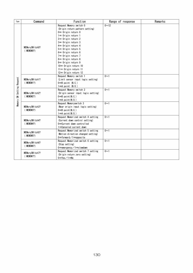
130
Type Command Function Range of response Remarks
:MEMorySWitch0?
(:MEMSW0?)
Request Memory switch 0
(Origin return pattern setting)
0⇒ Origin return 0
1⇒ Origin return 1
2⇒ Origin return 2
3⇒ Origin return 3
4⇒ Origin return 4
5⇒ Origin return 5
6⇒ Origin return 6
7⇒ Origin return 7
8⇒ Origin return 8
9⇒ Origin return 9
10⇒ Origin return 10
11⇒ Origin return 11
12⇒ Origin return 12
0~12
:MEMorySWitch1?
(:MEMSW1?)
Request Memory switch 1
(Limit sensor input logic setting)
0⇒B point (N.C.)
1⇒A point (N.O.)
0~1
:MEMorySWitch2?
(:MEMSW2?)
Request Memory switch 2
(Origin sensor input logic setting)
0⇒B point(N.C.)
1⇒A point(N.O.)
0~1
:MEMorySWitch3?
(:MEMSW3?)
Request Memoryswitch 3
(Near origin input logic setting)
0⇒B point(N.C.)
1⇒A point(N.O.)
0~1
:MEMorySWitch4?
(:MEMSW4?)
Request Memorized switch 4 setting
(Current down control setting)
0⇒Current down controlled
1⇒Canceled current down
0~1
:MEMorySWitch5?
(:MEMSW5?)
Request Memorized switch 5 setting
(Motion direction changed setting)
0⇒forward/1⇒opposite
0~1
:MEMorySWitch6?
(:MEMSW6?)
Request Memorized switch 6 setting
(Stop setting)
0⇒emergency/1⇒slowdown
0~1
Memory SW Setting Request
:MEMorySWitch7?
(:MEMSW7?)
Request Memorized switch 7 setting
(Origin return zero setting)
0⇒Yes/1⇒No
0~1
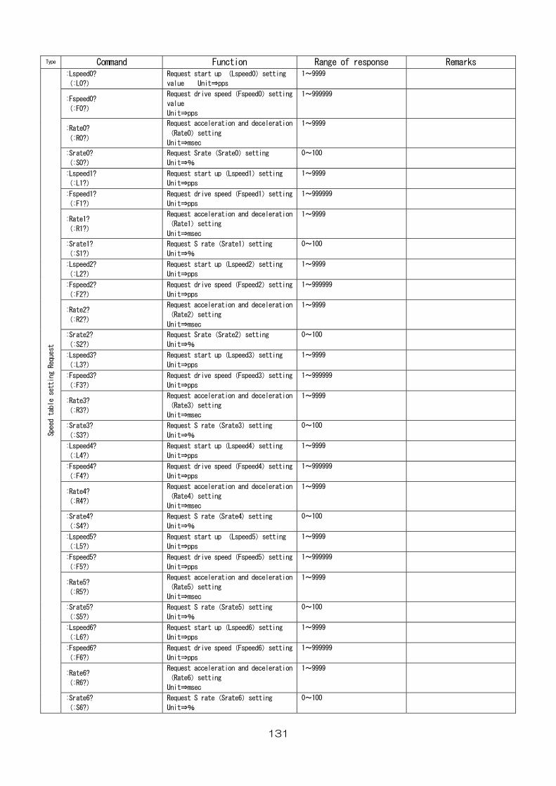
131
Type Command Function Range of response Remarks :Lspeed0?
(:L0?)
Request start up (Lspeed0)setting
value Unit⇒pps
1~9999
:Fspeed0?
(:F0?)
Request drive speed(Fspeed0)setting
value
Unit⇒pps
1~999999
:Rate0?
(:R0?)
Request acceleration and deceleration
(Rate0)setting
Unit⇒msec
1~9999
:Srate0?
(:S0?)
Request Srate(Srate0)setting
Unit⇒%
0~100
:Lspeed1?
(:L1?)
Request start up(Lspeed1)setting
Unit⇒pps
1~9999
:Fspeed1?
(:F1?)
Request drive speed(Fspeed1)setting
Unit⇒pps
1~999999
:Rate1?
(:R1?)
Request acceleration and deceleration
(Rate1)setting
Unit⇒msec
1~9999
:Srate1?
(:S1?)
Request S rate(Srate1)setting
Unit⇒%
0~100
:Lspeed2?
(:L2?)
Request start up(Lspeed2)setting
Unit⇒pps
1~9999
:Fspeed2?
(:F2?)
Request drive speed(Fspeed2)setting
Unit⇒pps
1~999999
:Rate2?
(:R2?)
Request acceleration and deceleration
(Rate2)setting
Unit⇒msec
1~9999
:Srate2?
(:S2?)
Request Srate(Srate2)setting
Unit⇒%
0~100
:Lspeed3?
(:L3?)
Request start up(Lspeed3)setting
Unit⇒pps
1~9999
:Fspeed3?
(:F3?)
Request drive speed(Fspeed3)setting
Unit⇒pps
1~999999
:Rate3?
(:R3?)
Request acceleration and deceleration
(Rate3)setting
Unit⇒msec
1~9999
:Srate3?
(:S3?)
Request S rate(Srate3)setting
Unit⇒%
0~100
:Lspeed4?
(:L4?)
Request start up(Lspeed4)setting
Unit⇒pps
1~9999
:Fspeed4?
(:F4?)
Request drive speed(Fspeed4)setting
Unit⇒pps
1~999999
:Rate4?
(:R4?)
Request acceleration and deceleration
(Rate4)setting
Unit⇒msec
1~9999
:Srate4?
(:S4?)
Request S rate (Srate4) setting
Unit⇒%
0~100
:Lspeed5?
(:L5?)
Request start up (Lspeed5)setting
Unit⇒pps
1~9999
:Fspeed5?
(:F5?)
Request drive speed(Fspeed5)setting
Unit⇒pps
1~999999
:Rate5?
(:R5?)
Request acceleration and deceleration
(Rate5)setting
Unit⇒msec
1~9999
:Srate5?
(:S5?)
Request S rate(Srate5)setting
Unit⇒%
0~100
:Lspeed6?
(:L6?)
Request start up(Lspeed6)setting
Unit⇒pps
1~9999
:Fspeed6?
(:F6?)
Request drive speed(Fspeed6)setting
Unit⇒pps
1~999999
:Rate6?
(:R6?)
Request acceleration and deceleration
(Rate6)setting
Unit⇒msec
1~9999
Speed table setting Request
:Srate6?
(:S6?)
Request S rate(Srate6)setting
Unit⇒%
0~100
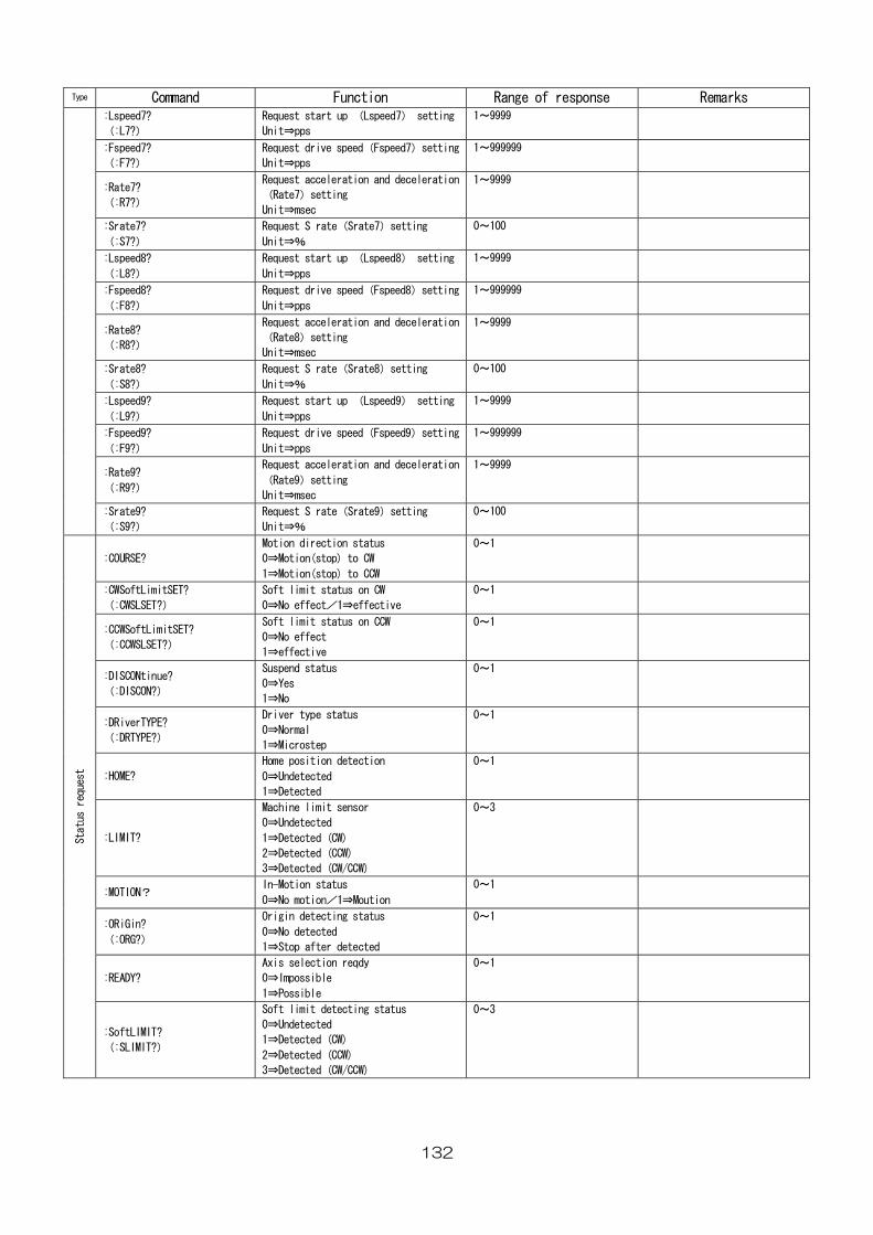
132
Type Command Function Range of response Remarks :Lspeed7?
(:L7?)
Request start up (Lspeed7) setting
Unit⇒pps
1~9999
:Fspeed7?
(:F7?)
Request drive speed(Fspeed7)setting
Unit⇒pps
1~999999
:Rate7?
(:R7?)
Request acceleration and deceleration
(Rate7)setting
Unit⇒msec
1~9999
:Srate7?
(:S7?)
Request S rate(Srate7)setting
Unit⇒%
0~100
:Lspeed8?
(:L8?)
Request start up (Lspeed8) setting
Unit⇒pps
1~9999
:Fspeed8?
(:F8?)
Request drive speed(Fspeed8)setting
Unit⇒pps
1~999999
:Rate8?
(:R8?)
Request acceleration and deceleration
(Rate8)setting
Unit⇒msec
1~9999
:Srate8?
(:S8?)
Request S rate(Srate8)setting
Unit⇒%
0~100
:Lspeed9?
(:L9?)
Request start up (Lspeed9) setting
Unit⇒pps
1~9999
:Fspeed9?
(:F9?)
Request drive speed(Fspeed9)setting
Unit⇒pps
1~999999
:Rate9?
(:R9?)
Request acceleration and deceleration
(Rate9)setting
Unit⇒msec
1~9999
:Srate9?
(:S9?)
Request S rate(Srate9)setting
Unit⇒%
0~100
:COURSE?
Motion direction status
0⇒Motion(stop) to CW
1⇒Motion(stop) to CCW
0~1
:CWSoftLimitSET?
(:CWSLSET?)
Soft limit status on CW
0⇒No effect/1⇒effective
0~1
:CCWSoftLimitSET?
(:CCWSLSET?)
Soft limit status on CCW
0⇒No effect
1⇒effective
0~1
:DISCONtinue?
(:DISCON?)
Suspend status
0⇒Yes
1⇒No
0~1
:DRiverTYPE?
(:DRTYPE?)
Driver type status
0⇒Normal
1⇒Microstep
0~1
:HOME?
Home position detection
0⇒Undetected
1⇒Detected
0~1
:LIMIT?
Machine limit sensor
0⇒Undetected
1⇒Detected (CW)
2⇒Detected (CCW)
3⇒Detected (CW/CCW)
0~3
:MOTION? In-Motion status
0⇒No motion/1⇒Moution
0~1
:ORiGin?
(:ORG?)
Origin detecting status
0⇒No detected
1⇒Stop after detected
0~1
:READY?
Axis selection reqdy
0⇒Impossible
1⇒Possible
0~1
Status request
:SoftLIMIT?
(:SLIMIT?)
Soft limit detecting status
0⇒Undetected
1⇒Detected (CW)
2⇒Detected (CCW)
3⇒Detected (CW/CCW)
0~3
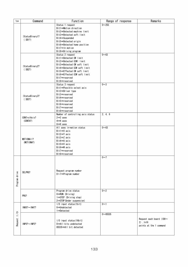
133
Type Command Function Range of response Remarks
:StatusBinary1?
(:SB1?)
Status 1 request
Bit1⇒Motion direction
Bit2⇒Detected machine limit
Bit3⇒Detected soft limit
Bit4⇒Suspended
Bit5⇒Detected origin
Bit6⇒Detected home position
Bit7⇒In motion
Bit8⇒Driving program
0~255
:StatusBinary2?
(:SB2?)
Status 2 request
Bit1⇒Detected CW limit
Bit2⇒Detected CCWl limit
Bit3⇒Detected CW soft limit
Bit4⇒Detected CCW soft limit
Bit5⇒Effected CW soft limit
Bit6⇒Effected CCW soft limit
Bit7⇒reserved
Bit8⇒reserved
0~63
:StatusBinary3?
(:SB3?)
Status 3 request
Bit1⇒Possible select axis
Bit2⇒Driver type
Bit3⇒reserved
Bit4⇒reserved
Bit5⇒reserved
Bit6⇒reserved
Bit7⇒reserved
Bit8⇒reserved
0~3
CONTrolAxis?
(CONTA?)
Number of controlling axis status
2⇒2 axes
4⇒4 axes
6⇒6 axes
2, 4, 6
MOTIONAll?
(MOTIONA?)
All axes in-motion status
Bit1⇒X axis
Bit2⇒Y axis
Bit3⇒Z axis
Bit4⇒U axis
Bit5⇒V axis
Bit6⇒W axis
Bit7⇒reserved
Bit8⇒reserved
0~63
SELPRG? Request program number
0~7⇒Program number
0~7
Program drive
PRG?
Program drive status
0⇒RUN(Driving)
1⇒STEP(Driving step)
2⇒STOP(Under suspension)
0~2
IN00?~IN47?
I/O input status(1bit)
0⇒Undetected
1⇒Detected
0~1
Request I/O
INP0?~INP2?
I/O input status(16bit)
0⇒All bits undetected
65535⇒All bit detected
0~65535
Request each board(ID0~
2),In16
points at the 1 command
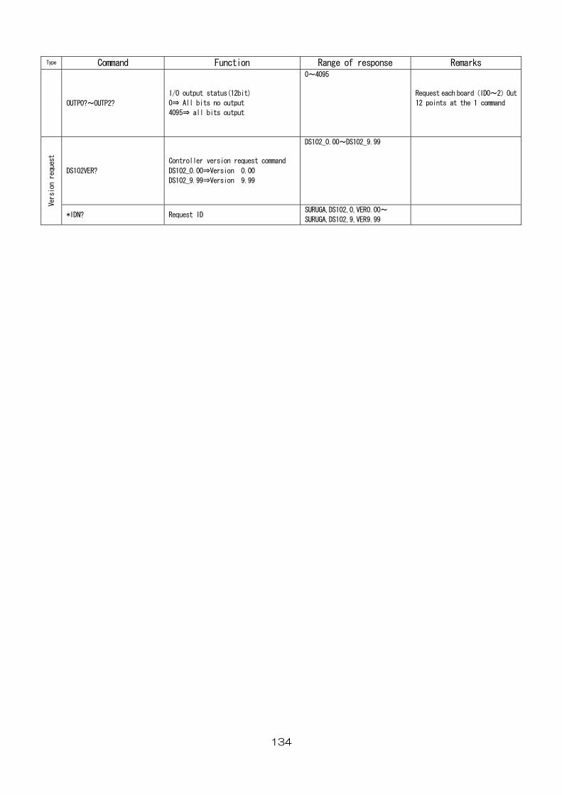
134
Type Command Function Range of response Remarks
OUTP0?~OUTP2?
I/O output status(12bit)
0⇒ All bits no output
4095⇒ all bits output
0~4095
Request each board(ID0~2)Out
12 points at the 1 command
DS102VER?
Controller version request command
DS102_0.00⇒Version 0.00
DS102_9.99⇒Version 9.99
DS102_0.00~DS102_9.99
Version request
*IDN? Request ID SURUGA,DS102,0,VER0.00~
SURUGA,DS102,9,VER9.99
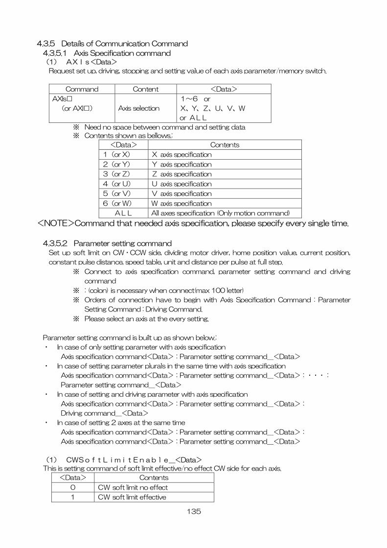
135
4.3.5 Details of Communication Command
4.3.5.1 Axis Specification command
(1) AXIs<Data>
Request set up, driving, stopping and setting value of each axis parameter/memory switch.
Command Content <Data>
AXIs□
(or AXI□) Axis selection
1~6 or
X、Y、Z、U、V、W
or ALL
※ Need no space between command and setting data
※ Contents shown as bellows.:
<Data> Contents
1(or X) X axis specification
2(or Y) Y axis specification
3(or Z) Z axis specification
4(or U) U axis specification
5(or V) V axis specification
6(or W) W axis specification
ALL All axes specification (Only motion command)
<NOTE>Command that needed axis specification, please specify every single time.
4.3.5.2 Parameter setting command
Set up soft limit on CW・CCW side, dividing motor driver, home position value, current position,
constant pulse distance, speed table, unit and distance per pulse at full step.
※ Connect to axis specification command, parameter setting command and driving
command
※ : (colon) is necessary when connect(max 100 letter)
※ Orders of connection have to begin with Axis Specification Command : Parameter
Setting Command : Driving Command.
※ Please select an axis at the every setting.
Parameter setting command is built up as shown below.:
・ In case of only setting parameter with axis specification
Axis specification command<Data>:Parameter setting command_<Data>
・ In case of setting parameter plurals in the same time with axis specification
Axis specification command<Data>:Parameter setting command_<Data>:・・・:
Parameter setting command_<Data>
・ In case of setting and driving parameter with axis specification
Axis specification command<Data>:Parameter setting command_<Data>:
Driving command_<Data>
・ In case of setting 2 axes at the same time
Axis specification command<Data>:Parameter setting command_<Data>:
Axis specification command<Data>:Parameter setting command_<Data>
(1) CWSoftLimitEnable_<Data>
This is setting command of soft limit effective/no effect CW side for each axis.
<Data> Contents
0 CW soft limit no effect
1 CW soft limit effective
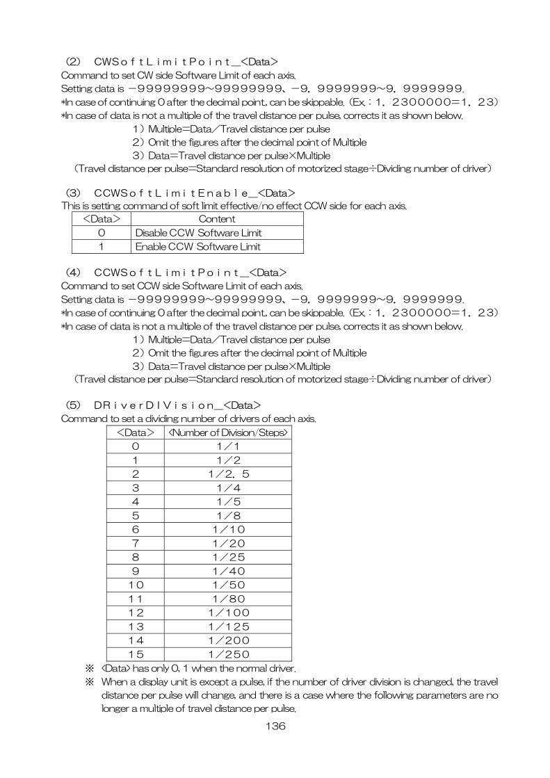
136
(2) CWSoftLimitPoint_<Data>
Command to set CW side Software Limit of each axis.
Setting data is -99999999~99999999、-9.9999999~9.9999999.
*In case of continuing 0 after the decimal point., can be skippable.(Ex.:1.2300000=1.23)
*In case of data is not a multiple of the travel distance per pulse, corrects it as shown below.
1)Multiple=Data/Travel distance per pulse
2)Omit the figures after the decimal point of Multiple
3)Data=Travel distance per pulse×Multiple
(Travel distance per pulse=Standard resolution of motorized stage÷Dividing number of driver)
(3) CCWSoftLimitEnable_<Data>
This is setting command of soft limit effective/no effect CCW side for each axis.
<Data> Content
0 Disable CCW Software Limit
1 Enable CCW Software Limit
(4) CCWSoftLimitPoint_<Data>
Command to set CCW side Software Limit of each axis.
Setting data is -99999999~99999999、-9.9999999~9.9999999.
*In case of continuing 0 after the decimal point., can be skippable.(Ex.:1.2300000=1.23)
*In case of data is not a multiple of the travel distance per pulse, corrects it as shown below.
1)Multiple=Data/Travel distance per pulse
2)Omit the figures after the decimal point of Multiple
3)Data=Travel distance per pulse×Multiple
(Travel distance per pulse=Standard resolution of motorized stage÷Dividing number of driver)
(5) DRiverDIVision_<Data>
Command to set a dividing number of drivers of each axis.
<Data> <Number of Division/Steps>
0 1/1
1 1/2
2 1/2.5
3 1/4
4 1/5
5 1/8
6 1/10
7 1/20
8 1/25
9 1/40
10 1/50
11 1/80
12 1/100
13 1/125
14 1/200
15 1/250
※ <Data> has only 0, 1 when the normal driver.
※ When a display unit is except a pulse, if the number of driver division is changed, the travel
distance per pulse will change, and there is a case where the following parameters are no
longer a multiple of travel distance per pulse.
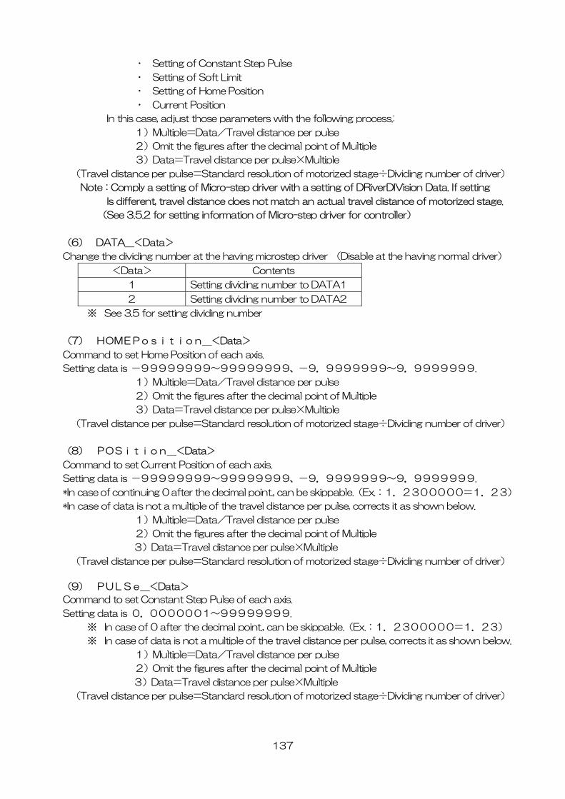
137
・ Setting of Constant Step Pulse
・ Setting of Soft Limit
・ Setting of Home Position
・ Current Position
In this case, adjust those parameters with the following process.:
1)Multiple=Data/Travel distance per pulse
2)Omit the figures after the decimal point of Multiple
3)Data=Travel distance per pulse×Multiple
(Travel distance per pulse=Standard resolution of motorized stage÷Dividing number of driver)
Note:Comply a setting of Micro-step driver with a setting of DRiverDIVision Data. If setting
Is different, travel distance does not match an actual travel distance of motorized stage.
(See 3.5.2 for setting information of Micro-step driver for controller)
(6) DATA_<Data>
Change the dividing number at the having microstep driver (Disable at the having normal driver)
<Data> Contents
1 Setting dividing number to DATA1
2 Setting dividing number to DATA2
※ See 3.5 for setting dividing number
(7) HOMEPosition_<Data>
Command to set Home Position of each axis.
Setting data is -99999999~99999999、-9.9999999~9.9999999.
1)Multiple=Data/Travel distance per pulse
2)Omit the figures after the decimal point of Multiple
3)Data=Travel distance per pulse×Multiple
(Travel distance per pulse=Standard resolution of motorized stage÷Dividing number of driver)
(8) POSition_<Data>
Command to set Current Position of each axis.
Setting data is -99999999~99999999、-9.9999999~9.9999999.
*In case of continuing 0 after the decimal point., can be skippable.(Ex.:1.2300000=1.23)
*In case of data is not a multiple of the travel distance per pulse, corrects it as shown below.
1)Multiple=Data/Travel distance per pulse
2)Omit the figures after the decimal point of Multiple
3)Data=Travel distance per pulse×Multiple
(Travel distance per pulse=Standard resolution of motorized stage÷Dividing number of driver)
(9) PULSe_<Data>
Command to set Constant Step Pulse of each axis.
Setting data is 0.0000001~99999999.
※ In case of 0 after the decimal point., can be skippable.(Ex.:1.2300000=1.23)
※ In case of data is not a multiple of the travel distance per pulse, corrects it as shown below.
1)Multiple=Data/Travel distance per pulse
2)Omit the figures after the decimal point of Multiple
3)Data=Travel distance per pulse×Multiple
(Travel distance per pulse=Standard resolution of motorized stage÷Dividing number of driver)
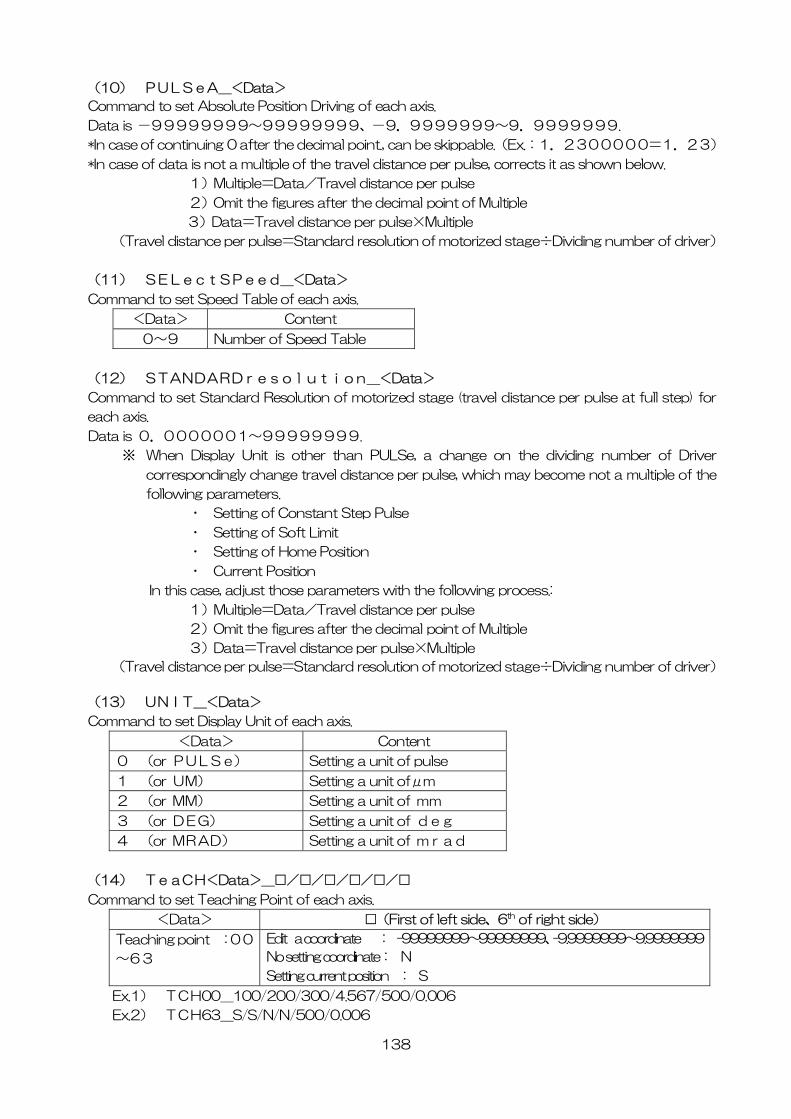
138
(10) PULSeA_<Data>
Command to set Absolute Position Driving of each axis.
Data is -99999999~99999999、-9.9999999~9.9999999.
*In case of continuing 0 after the decimal point., can be skippable.(Ex.:1.2300000=1.23)
*In case of data is not a multiple of the travel distance per pulse, corrects it as shown below.
1)Multiple=Data/Travel distance per pulse
2)Omit the figures after the decimal point of Multiple
3)Data=Travel distance per pulse×Multiple
(Travel distance per pulse=Standard resolution of motorized stage÷Dividing number of driver)
(11) SELectSPeed_<Data>
Command to set Speed Table of each axis.
<Data> Content
0~9 Number of Speed Table
(12) STANDARDresolution_<Data>
Command to set Standard Resolution of motorized stage (travel distance per pulse at full step) for
each axis.
Data is 0.0000001~99999999.
※ When Display Unit is other than PULSe, a change on the dividing number of Driver
correspondingly change travel distance per pulse, which may become not a multiple of the
following parameters.
・ Setting of Constant Step Pulse
・ Setting of Soft Limit
・ Setting of Home Position
・ Current Position
In this case, adjust those parameters with the following process.:
1)Multiple=Data/Travel distance per pulse
2)Omit the figures after the decimal point of Multiple
3)Data=Travel distance per pulse×Multiple
(Travel distance per pulse=Standard resolution of motorized stage÷Dividing number of driver)
(13) UNIT_<Data>
Command to set Display Unit of each axis.
<Data> Content
0 (or PULSe) Setting a unit of pulse
1 (or UM) Setting a unit ofμm
2 (or MM) Setting a unit of mm
3 (or DEG) Setting a unit of deg
4 (or MRAD) Setting a unit of mrad
(14) TeaCH<Data>_□/□/□/□/□/□
Command to set Teaching Point of each axis.
<Data> □(First of left side、6th of right side)
Teaching point :00
~63
Edit a coordinate : -99999999~99999999、-9.9999999~9.9999999
No setting coordinate: N
Setting current position : S
Ex.1) TCH00_100/200/300/4.567/500/0.006
Ex.2) TCH63_S/S/N/N/500/0.006
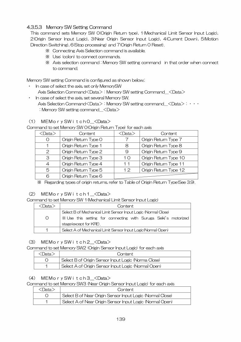
139
4.3.5.3 Memory SW Setting Command
This command sets Memory SW 0(Origin Return type), 1(Mechanical Limit Sensor Input Logic),
2(Origin Sensor Input Logic), 3(Near Origin Sensor Input Logic), 4(Current Down), 5(Motion
Direction Switching), 6(Stop processing) and 7(Origin Return 0 Reset).
※ Connecting Axis Selection command is available.
※ Use: (colon) to connect commands.
※ Axis selection command : Memory SW setting command in that order when connect
to command.
Memory SW setting Command is configured as shown below.:
・ In case of select the axis, set only MemorySW
Axis Selection Command<Data>:Memory SW setting Command_<Data>
・ In case of select the axis, set several Memory SW.
Axis Selection Command<Data>:Memory SW setting command_<Data>:・・・
:Memory SW setting command_<Data>
(1) MEMorySWitch0_<Data>
Command to set Memory SW 0(Origin Return Type) for each axis
<Data> Content <Data> Content
0 Origin Return Type 0 7 Origin Return Type 7
1 Origin Return Type 1 8 Origin Return Type 8
2 Origin Return Type 2 9 Origin Return Type 9
3 Origin Return Type 3 10 Origin Return Type 10
4 Origin Return Type 4 11 Origin Return Type 11
5 Origin Return Type 5 12 Origin Return Type 12
6 Origin Return Type 6
※ Regarding types of origin returns, refer to Table of Origin Return Type(See 3.9).
(2) MEMorySWitch1_<Data>
Command to set Memory SW 1(Mechanical Limit Sensor Input Logic)
<Data> Content
0
Select B of Mechanical Limit Sensor Input Logic (Normal Close)
※ Use this setting for connecting with Suruga Seiki’s motorized
stage(except for KRE).
1 Select A of Mechanical Limit Sensor Input Logic(Normal Open)
(3) MEMorySWitch2_<Data>
Command to set Memory SW2 (Origin Sensor Input Logic) for each axis
<Data> Content
0 Select B of Origin Sensor Input Logic (Norma Close)
1 Select A of Origin Sensor Input Logic (Normal Open)
(4) MEMorySWitch3_<Data>
Command to set Memory SW3 (Near Origin Sensor Input Logic) for each axis
<Data> Content
0 Select B of Near Origin Sensor Input Logic (Normal Close)
1 Select A of Near Origin Sensor Input Logic (Normal Open)
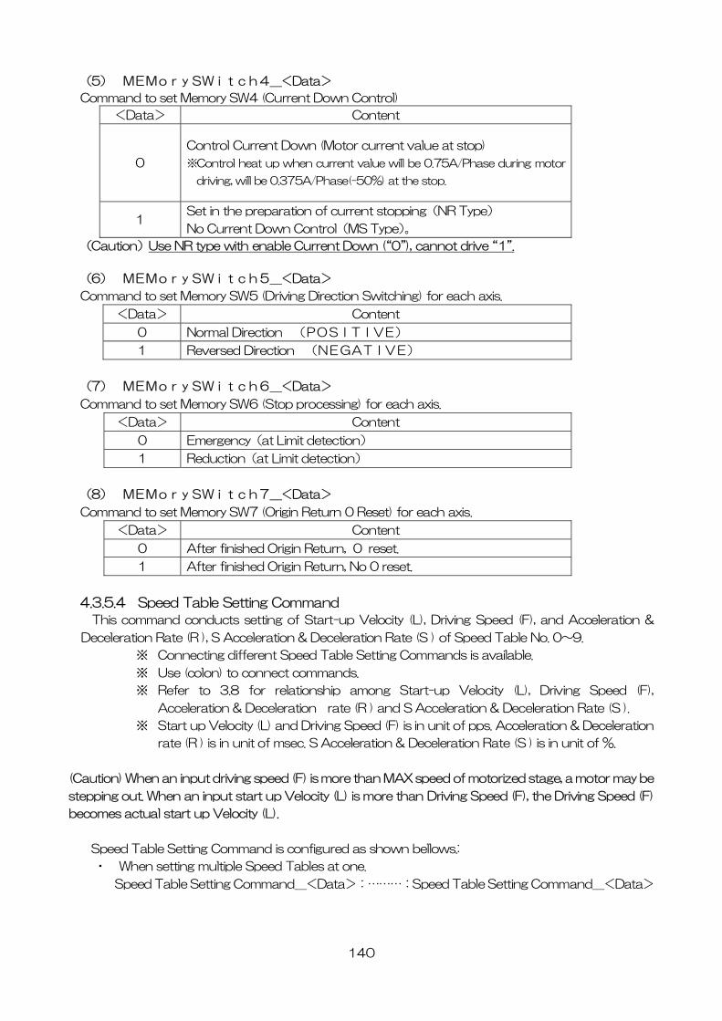
140
(5) MEMorySWitch4_<Data>
Command to set Memory SW4 (Current Down Control)
<Data> Content
0
Control Current Down (Motor current value at stop)
※Control heat up when current value will be 0.75A/Phase during motor
driving, will be 0.375A/Phase(-50%) at the stop.
1 Set in the preparation of current stopping(NR Type)
No Current Down Control(MS Type)。
(Caution)Use NR type with enable Current Down (“0”), cannot drive “1”.
(6) MEMorySWitch5_<Data>
Command to set Memory SW5 (Driving Direction Switching) for each axis.
<Data> Content
0 Normal Direction (POSITIVE)
1 Reversed Direction (NEGATIVE)
(7) MEMorySWitch6_<Data>
Command to set Memory SW6 (Stop processing) for each axis.
<Data> Content
0 Emergency(at Limit detection)
1 Reduction(at Limit detection)
(8) MEMorySWitch7_<Data>
Command to set Memory SW7 (Origin Return 0 Reset) for each axis.
<Data> Content
0 After finished Origin Return, 0 reset.
1 After finished Origin Return, No 0 reset.
4.3.5.4 Speed Table Setting Command
This command conducts setting of Start-up Velocity (L), Driving Speed (F), and Acceleration &
Deceleration Rate (R ), S Acceleration & Deceleration Rate (S ) of Speed Table No. 0~9.
※ Connecting different Speed Table Setting Commands is available.
※ Use (colon) to connect commands.
※ Refer to 3.8 for relationship among Start-up Velocity (L), Driving Speed (F),
Acceleration & Deceleration rate (R ) and S Acceleration & Deceleration Rate (S ).
※ Start up Velocity (L) and Driving Speed (F) is in unit of pps. Acceleration & Deceleration
rate (R ) is in unit of msec. S Acceleration & Deceleration Rate (S ) is in unit of %.
(Caution) When an input driving speed (F) is more than MAX speed of motorized stage, a motor may be
stepping out. When an input start up Velocity (L) is more than Driving Speed (F), the Driving Speed (F)
becomes actual start up Velocity (L).
Speed Table Setting Command is configured as shown bellows.:
・ When setting multiple Speed Tables at one.
Speed Table Setting Command_<Data>:………:Speed Table Setting Command_<Data>
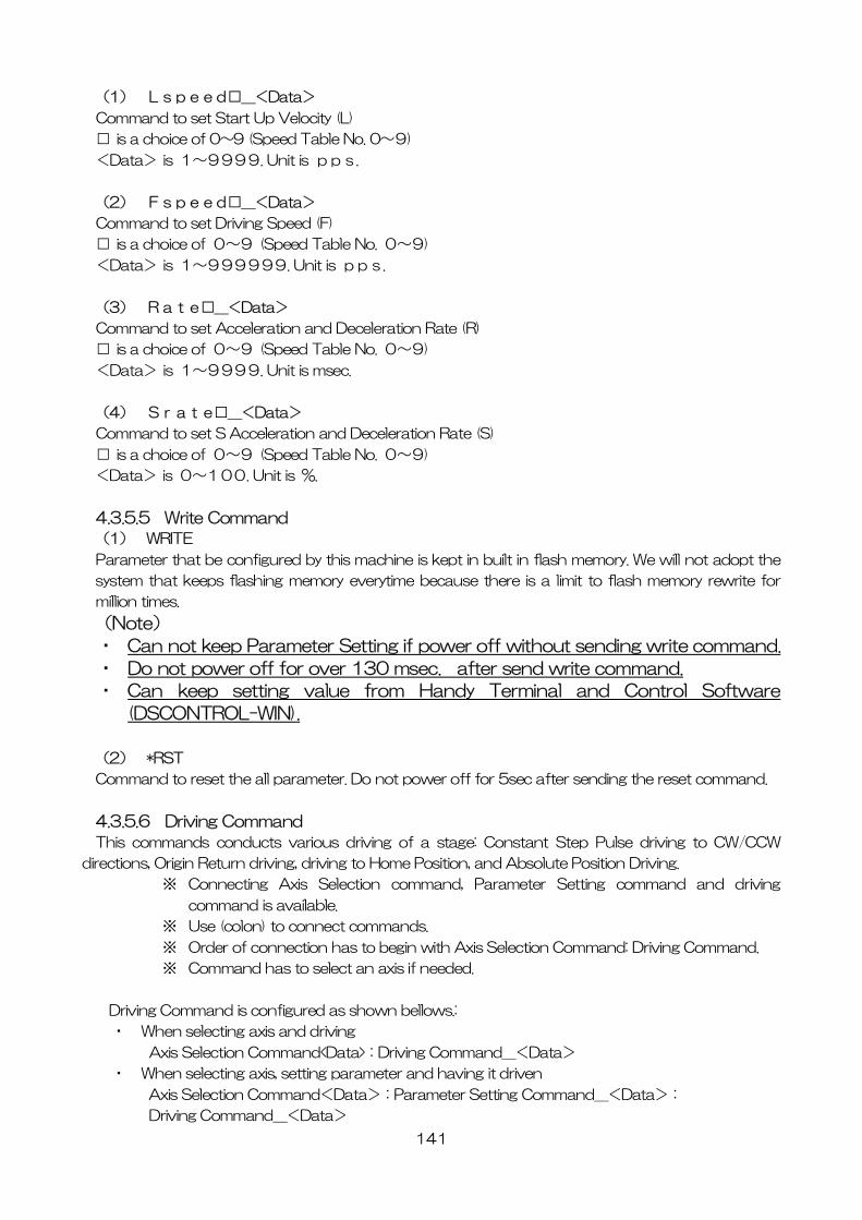
141
(1) Lspeed□_<Data>
Command to set Start Up Velocity (L)
□ is a choice of 0~9 (Speed Table No. 0~9)
<Data> is 1~9999. Unit is pps.
(2) Fspeed□_<Data>
Command to set Driving Speed (F)
□ is a choice of 0~9 (Speed Table No. 0~9)
<Data> is 1~999999. Unit is pps.
(3) Rate□_<Data>
Command to set Acceleration and Deceleration Rate (R)
□ is a choice of 0~9 (Speed Table No. 0~9)
<Data> is 1~9999. Unit is msec.
(4) Srate□_<Data>
Command to set S Acceleration and Deceleration Rate (S)
□ is a choice of 0~9 (Speed Table No. 0~9)
<Data> is 0~100. Unit is %.
4.3.5.5 Write Command
(1) WRITE
Parameter that be configured by this machine is kept in built in flash memory. We will not adopt the
system that keeps flashing memory everytime because there is a limit to flash memory rewrite for
million times.
(Note)
・ Can not keep Parameter Setting if power off without sending write command.
・ Do not power off for over 130 msec. after send write command.
・ Can keep setting value from Handy Terminal and Control Software
(DSCONTROL-WIN).
(2) *RST
Command to reset the all parameter. Do not power off for 5sec after sending the reset command.
4.3.5.6 Driving Command
This commands conducts various driving of a stage: Constant Step Pulse driving to CW/CCW
directions, Origin Return driving, driving to Home Position, and Absolute Position Driving.
※ Connecting Axis Selection command, Parameter Setting command and driving
command is available.
※ Use (colon) to connect commands.
※ Order of connection has to begin with Axis Selection Command: Driving Command.
※ Command has to select an axis if needed.
Driving Command is configured as shown bellows.:
・ When selecting axis and driving
Axis Selection Command<Data>:Driving Command_<Data>
・ When selecting axis, setting parameter and having it driven
Axis Selection Command<Data>:Parameter Setting Command_<Data>:
Driving Command_<Data>
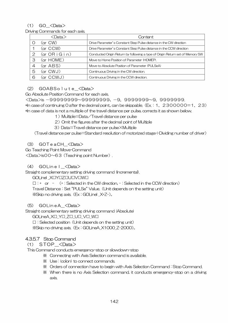
142
(1) GO_<Data>
Driving Commands for each axis.
<Data> Content
0 (or CW) Drive Parameter’s Constant Step Pulse distance in the CW direction
1 (or CCW) Drive Parameter’s Constant Step Pulse distance in the CCW direction
2 (or ORiGin) Conducted Origin Return by following a type of Origin Return set of Memory SW
3 (or HOME) Move to Home Position of Parameter (HOMEP).
4 (or ABS) Move to Absolute Position of Parameter (PULSeA)
5 (or CWJ) Continuous Driving in the CW direction.
6 (or CCWJ) Continuous Driving in the CCW direction.
(2) GOABSolute_<Data>
Go Absolute Position Command for each axis.
<Data>is -99999999~99999999、-9.9999999~9.9999999.
*In case of continuing 0 after the decimal point., can be skippable.(Ex.:1.2300000=1.23)
*In case of data is not a multiple of the travel distance per pulse, corrects it as shown below.
1)Multiple=Data/Travel distance per pulse
2)Omit the figures after the decimal point of Multiple
3)Data=Travel distance per pulse×Multiple
(Travel distance per pulse=Standard resolution of motorized stage÷Dividing number of driver)
(3) GOTeaCH_<Data>
Go Teaching Point Move-Command
<Data>is00~63(Teaching point Number).
(4) GOLineI_<Data>
Straight complementary setting driving command (Incremental).
GOLineI _X□Y□Z□U□V□W□
□:+ or - (+:Selected in the CW direction, -:Selected in the CCW direction)
Travel Distance:Set ”PULSe” Value.(Unit depends on the setting unit)
※Skip no driving axis.(Ex:GOLineI _X+Z-)。
(5) GOLineA_<Data>
Straight complementary setting driving command (Absolute)
GOLineA_X□_Y□_Z□_U□_V□_W□
□:Selected position(Unit depends on the setting unit)
※Skip no driving axis.(Ex:GOLineA_X1000_Z-2000)。
4.3.5.7 Stop Command
(1) STOP_<Data>
This Command conducts emergency-stop or slowdown-stop
※ Connecting with Axis Selection command is available.
※ Use : (colon) to connect commands.
※ Orders of connection have to begin with Axis Selection Command : Stop Command.
※ When there is no Axis Selection command, it conducts emergency-stop on a driving
axis.
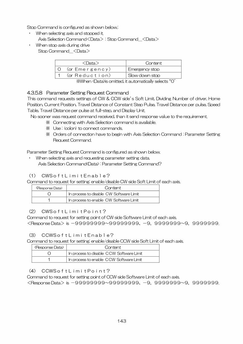
143
Stop Command is configured as shown below.:
・ When selecting axis and stopped it.
Axis Selection Command<Data>:Stop Command_<Data>
・ When stop axis during drive
Stop Command_<Data>
<Data> Content
0 (or Emergency) Emergency stop
1 (or Reduction) Slow down stop
※When <Data>is omitted, it automatically selects “0"
4.3.5.8 Parameter Setting Request Command
This command requests settings of CW & CCW side’s Soft Limit, Dividing Number of driver, Home
Position, Current Position, Travel Distance of Constant Step Pulse, Travel Distance per pulse, Speed
Table, Travel Distance per pulse at full-step, and Display Unit.
No sooner was request command received, than it send response value to the requirement.
※ Connecting with Axis Selection command is available.
※ Use : (colon) to connect commands.
※ Orders of connection have to begin with Axis Selection Command : Parameter Setting
Request Command.
Parameter Setting Request Command is configured as shown below.
・ When selecting axis and requesting parameter setting data.
Axis Selection Command<Data> : Parameter Setting Command?
(1) CWSoftLimitEnable?
Command to request for setting: enable/disable CW side Soft Limit of each axis.
<Response Data> Content
0 In process to disable CW Software Limit
1 In process to enable CW Software Limit
(2) CWSoftLimitPoint?
Command to request for setting point of CW side Software Limit of each axis.
<Response Data> is -99999999~99999999、-9.9999999~9.9999999.
(3) CCWSoftLimitEnable?
Command to request for setting: enable/disable CCW side Soft Limit of each axis.
<Response Data> Content
0 In process to disable CCW Software Limit
1 In process to enable CCW Software Limit
(4) CCWSoftLimitPoint?
Command to request for setting point of CCW side Software Limit of each axis.
<Response Data> is -99999999~99999999、-9.9999999~9.9999999.
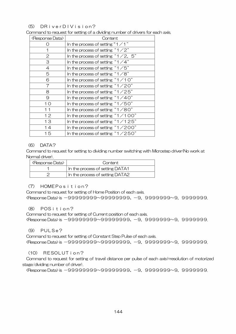
144
(5) DRiverDIVision?
Command to request for setting of a dividing number of drivers for each axis.
<Response Data> Content
0 In the process of setting “1/1”
1 In the process of setting“1/2”
2 In the process of setting“1/2.5”
3 In the process of setting“1/4”
4 In the process of setting“1/5”
5 In the process of setting“1/8”
6 In the process of setting“1/10”
7 In the process of setting“1/20”
8 In the process of setting“1/25”
9 In the process of setting“1/40”
10 In the process of setting“1/50”
11 In the process of setting“1/80”
12 In the process of setting“1/100”
13 In the process of setting“1/125”
14 In the process of setting“1/200”
15 In the process of setting“1/250”
(6) DATA?
Command to request for setting to dividing number switching with Microstep driver(No work at
Normal driver).
<Response Data> Content
1 In the process of setting DATA1
2 In the process of setting DATA2
(7) HOMEPosition?
Command to request for setting of Home Position of each axis.
<Response Data> is -99999999~99999999、-9.9999999~9.9999999.
(8) POSition?
Command to request for setting of Current position of each axis.
<Response Data> is -99999999~99999999、-9.9999999~9.9999999.
(9) PULSe?
Command to request for setting of Constant Step Pulse of each axis.
<Response Data> is -99999999~99999999、-9.9999999~9.9999999.
(10) RESOLUTion?
Command to request for setting of travel distance per pulse of each axis(=resolution of motorized
stage/dividing number of driver).
<Response Data> is -99999999~99999999、-9.9999999~9.9999999.
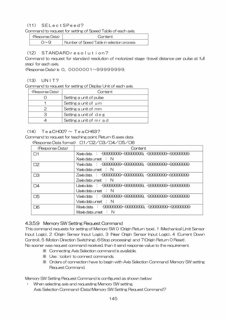
145
(11) SELectSPeed?
Command to request for setting of Speed Table of each axis.
<Response Data> Content
0~9 Number of Speed Table in selection process
(12) STANDARDresolution?
Command to request for standard resolution of motorized stage (travel distance per pulse at full
step) for each axis.
<Response Data> is 0.0000001~99999999.
(13) UNIT?
Command to request for setting of Display Unit of each axis.
<Response Data> Content
0 Setting a unit of pulse
1 Setting a unit of μm
2 Setting a unit of mm
3 Setting a unit of deg
4 Setting a unit of mrad
(14) TeaCH00? ~ TeaCH63?
Command to request for teaching point. Return 6 axes data
<Response Data format> □1/□2/□3/□4/□5/□6
<Response Data> Content
□1 Xaxis data : -99999999~99999999、-9.9999999~9.9999999
Xaxis data unset : N
□2 Yaxis data : -99999999~99999999、-9.9999999~9.9999999
Yaxis data unset : N
□3 Zaxis data : -99999999~99999999、-9.9999999~9.9999999
Zaxis data unset : N
□4 Uaxis data : -99999999~99999999、-9.9999999~9.9999999
Uaxis data unset : N
□5 Vaxis data : -99999999~99999999、-9.9999999~9.9999999
Vaxis data unset : N
□6 Waxis data : -99999999~99999999、-9.9999999~9.9999999
Waxis data unset : N
4.3.5.9 Memory SW Setting Request Command
This command requests for setting of Memory SW 0 (Origin Return type), 1 (Mechanical Limit Sensor
Input Logic), 2 (Origin Sensor Input Logic), 3 (Near Origin Sensor Input Logic), 4 (Current Down
Control), 5 (Motion Direction Switching), 6(Stop processing) and 7(Origin Return 0 Reset).
No sooner was request command received, than it send response value to the requirement.
※ Connecting Axis Selection command is available.
※ Use : (colon) to connect commands.
※ Orders of connection have to begin with Axis Selection Command: Memory SW setting
Request Command.
Memory SW Setting Request Command is configured as shown below:
・ When selecting axis and requesting Memory SW setting.
Axis Selection Command <Data>:Memory SW Setting Request Command?
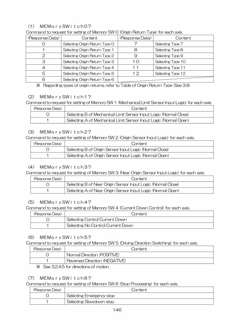
146
(1) MEMorySWitch0?
Command to request for setting of Memory SW 0 (Origin Return Type) for each axis.
<Response Data> Content <Response Data> Content
0 Selecting Origin Return Type 0 7 Selecting Type 7
1 Selecting Origin Return Type 1 8 Selecting Type 8
2 Selecting Origin Return Type 2 9 Selecting Type 9
3 Selecting Origin Return Type 3 10 Selecting Type 10
4 Selecting Origin Return Type 4 11 Selecting Type 11
5 Selecting Origin Return Type 5 12 Selecting Type 12
6 Selecting Origin Return Type 6
※ Regarding types of origin returns, refer to Table of Origin Return Type (See 3.9)
(2) MEMorySWitch1?
Command to request for setting of Memory SW 1 (Mechanical Limit Sensor Input Logic) for each axis.
<Response Data> Content
0 Selecting B of Mechanical Limit Sensor Input Logic (Normal Close)
1 Selecting A of Mechanical Limit Sensor Input Logic (Normal Open)
(3) MEMorySWitch2?
Command to request for setting of Memory SW 2 (Origin Sensor Input Logic) for each axis.
<Response Data> Content
0 Selecting B of Origin Sensor Input Logic (Normal Close)
1 Selecting A of Origin Sensor Input Logic (Normal Open)
(4) MEMorySWitch3?
Command to request for setting of Memory SW 3 (Near Origin Sensor Input Logic) for each axis.
<Response Data> Content
0 Selecting B of Near Origin Sensor Input Logic (Normal Close)
1 Selecting A of Near Origin Sensor Input Logic (Normal Open)
(5) MEMorySWitch4?
Command to request for setting of Memory SW 4 (Current Down Control) for each axis.
<Response Data> Content
0 Selecting Control Current Down
1 Selecting No Control Current Down
(6) MEMorySWitch5?
Command to request for setting of Memory SW 5 (Driving Direction Switching) for each axis.
<Response Data> Content
0 Normal Direction (POSITIVE)
1 Reversed Direction (NEGATIVE)
※ See 3.2.4.5 for directions of motion.
(7) MEMorySWitch6?
Command to request for setting of Memory SW 6 (Stop Processing) for each axis.
<Response Data> Content
0 Selecting Emergency stop
1 Selecting Slowdown stop
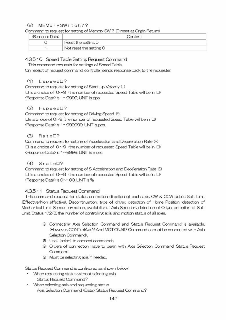
147
(8) MEMorySWitch7?
Command to request for setting of Memory SW 7 (0 reset at Origin Return)
<Response Data> Content
0 Reset the setting 0
1 Not reset the setting 0
4.3.5.10 Speed Table Setting Request Command
This command requests for settings of Speed Table.
On receipt of request command, controller sends response back to the requester.
(1) Lspeed□?
Command to request for setting of Start-up Velocity (L)
□ is a choice of 0~9 (the number of requested Speed Table will be in □)
<Response Data> is 1~9999. UNIT is pps.
(2) Fspeed□?
Command to request for setting of Driving Speed (F)
□is a choice of 0~9 (the number of requested Speed Table will be in □)
<Response Data> is 1~999999. UNIT is pps.
(3) Rate□?
Command to request for setting of Acceleration and Deceleration Rate (R)
□ is a choice of 0~9 (the number of requested Speed Table will be in □)
<Response Data> is 1~9999. UNIT is msec.
(4) Srate□?
Command to request for setting of S Acceleration and Deceleration Rate (S)
□ is a choice of 0~9 (the number of requested Speed Table will be in □)
<Response Data> is 0~100. UNIT is %
4.3.5.11 Status Request Command
This command request for status on motion direction of each axis, CW & CCW side’s Soft Limit
(Effective/Non-effective), Discontinuation, type of driver, detection of Home Position, detection of
Mechanical Limit Sensor, In-motion, availability of Axis Selection, detection of Origin, detection of Soft
Limit, Status 1/2/3, the number of controlling axis, and motion status of all axes.
※ Connecting Axis Selection Command and Status Request Command is available.
(However, CONTrolAxis? And MOTIONAII? Command cannot be connected with Axis
Selection Command).
※ Use : (colon) to connect commands.
※ Orders of connection have to begin with Axis Selection Command: Status Request
Command.
※ Must be selecting axis if needed.
Status Request Command is configured as shown below:
・ When requesting status without selecting axis
Status Request Command?
・ When selecting axis and requesting status
Axis Selection Command <Data>: Status Request Command?
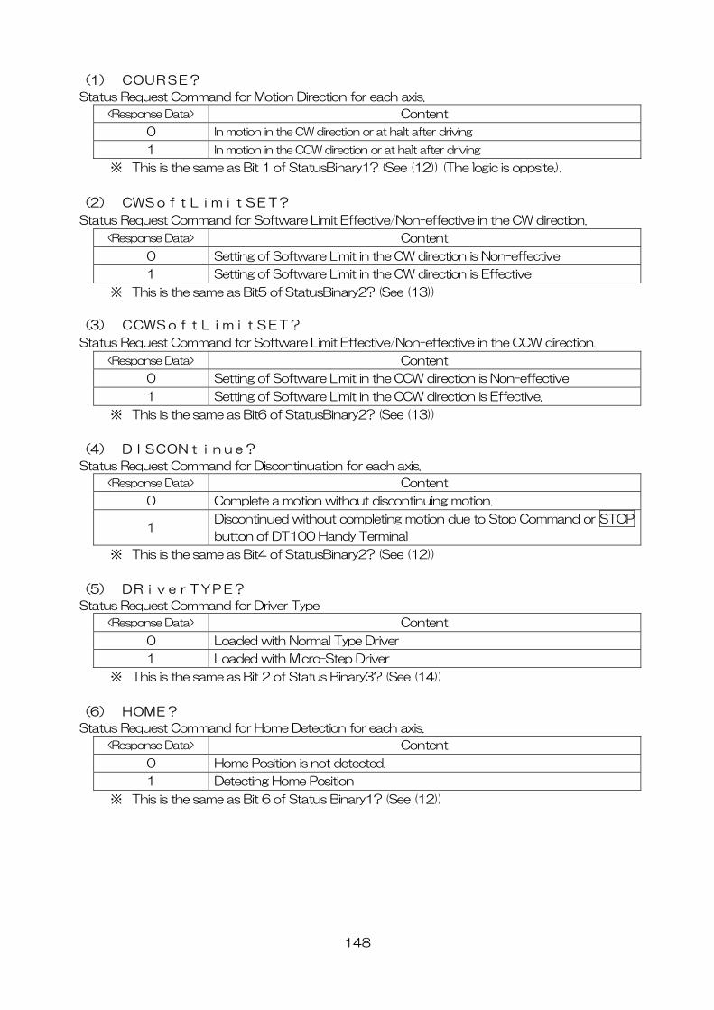
148
(1) COURSE?
Status Request Command for Motion Direction for each axis.
<Response Data> Content
0 In motion in the CW direction or at halt after driving
1 In motion in the CCW direction or at halt after driving
※ This is the same as Bit 1 of StatusBinary1? (See (12)) (The logic is oppsite.).
(2) CWSoftLimitSET?
Status Request Command for Software Limit Effective/Non-effective in the CW direction.
<Response Data> Content
0 Setting of Software Limit in the CW direction is Non-effective
1 Setting of Software Limit in the CW direction is Effective
※ This is the same as Bit5 of StatusBinary2? (See (13))
(3) CCWSoftLimitSET?
Status Request Command for Software Limit Effective/Non-effective in the CCW direction.
<Response Data> Content
0 Setting of Software Limit in the CCW direction is Non-effective
1 Setting of Software Limit in the CCW direction is Effective.
※ This is the same as Bit6 of StatusBinary2? (See (13))
(4) DISCONtinue?
Status Request Command for Discontinuation for each axis.
<Response Data> Content
0 Complete a motion without discontinuing motion.
1 Discontinued without completing motion due to Stop Command or STOP
button of DT100 Handy Terminal
※ This is the same as Bit4 of StatusBinary2? (See (12))
(5) DRiverTYPE?
Status Request Command for Driver Type
<Response Data> Content
0 Loaded with Normal Type Driver
1 Loaded with Micro-Step Driver
※ This is the same as Bit 2 of Status Binary3? (See (14))
(6) HOME?
Status Request Command for Home Detection for each axis.
<Response Data> Content
0 Home Position is not detected.
1 Detecting Home Position
※ This is the same as Bit 6 of Status Binary1? (See (12))
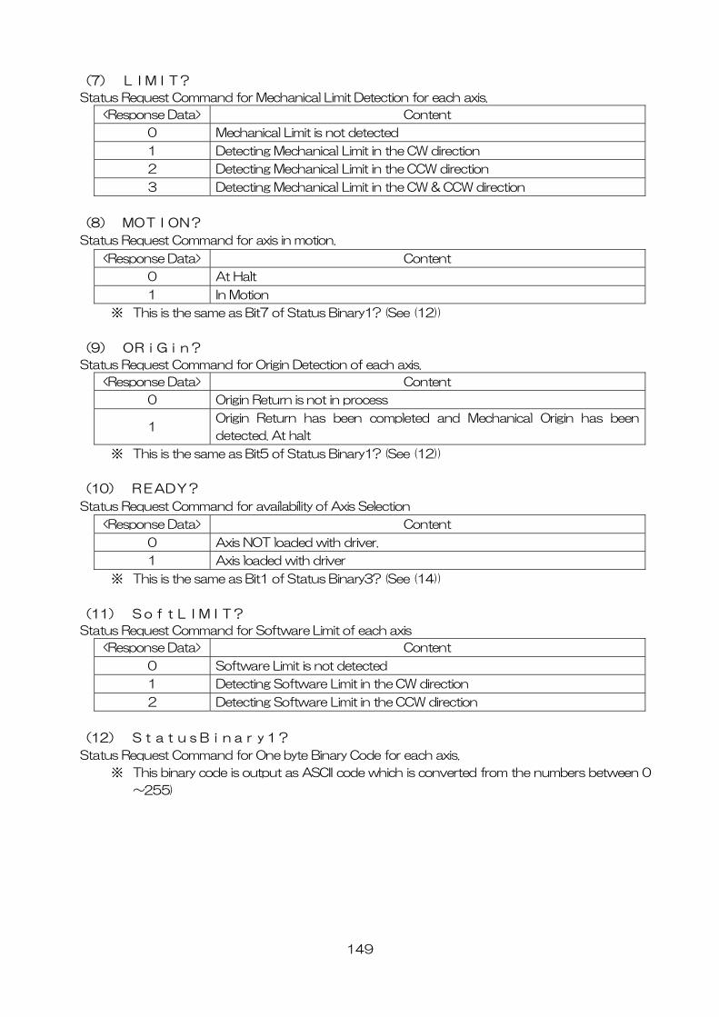
149
(7) LIMIT?
Status Request Command for Mechanical Limit Detection for each axis.
<Response Data> Content
0 Mechanical Limit is not detected
1 Detecting Mechanical Limit in the CW direction
2 Detecting Mechanical Limit in the CCW direction
3 Detecting Mechanical Limit in the CW & CCW direction
(8) MOTION?
Status Request Command for axis in motion.
<Response Data> Content
0 At Halt
1 In Motion
※ This is the same as Bit7 of Status Binary1? (See (12))
(9) ORiGin?
Status Request Command for Origin Detection of each axis.
<Response Data> Content
0 Origin Return is not in process
1 Origin Return has been completed and Mechanical Origin has been
detected. At halt
※ This is the same as Bit5 of Status Binary1? (See (12))
(10) READY?
Status Request Command for availability of Axis Selection
<Response Data> Content
0 Axis NOT loaded with driver.
1 Axis loaded with driver
※ This is the same as Bit1 of Status Binary3? (See (14))
(11) SoftLIMIT?
Status Request Command for Software Limit of each axis
<Response Data> Content
0 Software Limit is not detected
1 Detecting Software Limit in the CW direction
2 Detecting Software Limit in the CCW direction
(12) StatusBinary1?
Status Request Command for One byte Binary Code for each axis.
※ This binary code is output as ASCII code which is converted from the numbers between 0
~255)
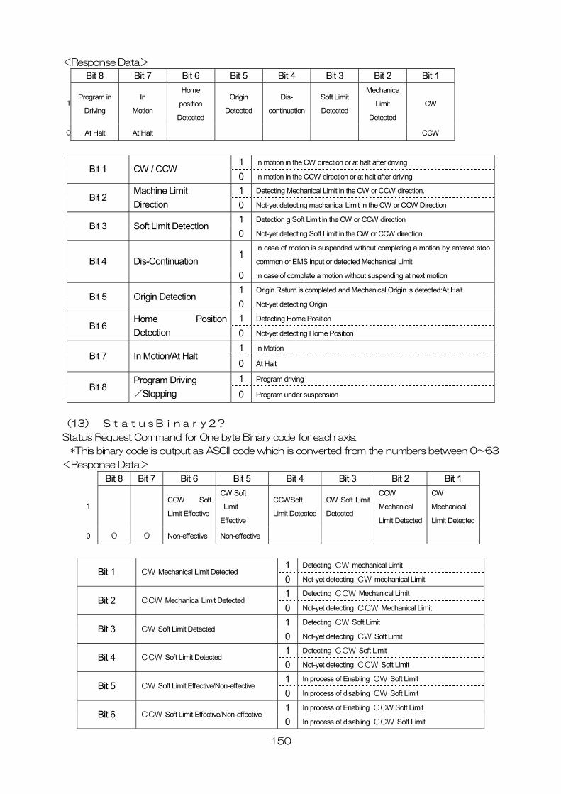
150
<Response Data>
Bit 8 Bit 7 Bit 6 Bit 5 Bit 4 Bit 3 Bit 2 Bit 1
1Program in
Driving
In
Motion
Home
position
Detected
Origin
Detected
Dis-
continuation
Soft Limit
Detected
Mechanica
Limit
Detected
CW
0 At Halt At Halt CCW
1 In motion in the CW direction or at halt after driving
Bit 1 CW / CCW 0 In motion in the CCW direction or at halt after driving
1 Detecting Mechanical Limit in the CW or CCW direction. Bit 2
Machine Limit Direction 0 Not-yet detecting machanical Limit in the CW or CCW Direction
1 Detection g Soft Limit in the CW or CCW direction Bit 3 Soft Limit Detection
0 Not-yet detecting Soft Limit in the CW or CCW direction
1In case of motion is suspended without completing a motion by entered stop
common or EMS input or detected Mechanical Limit Bit 4 Dis-Continuation 0 In case of complete a motion without suspending at next motion
1 Origin Return is completed and Mechanical Origin is detected:At Halt Bit 5 Origin Detection
0 Not-yet detecting Origin
1 Detecting Home Position Bit 6
Home Position Detection 0 Not-yet detecting Home Position
1 In Motion Bit 7 In Motion/At Halt
0 At Halt
1 Program driving Bit 8
Program Driving /Stopping 0 Program under suspension
(13) StatusBinary2?
Status Request Command for One byte Binary code for each axis.
*This binary code is output as ASCII code which is converted from the numbers between 0~63
<Response Data>
Bit 8 Bit 7 Bit 6 Bit 5 Bit 4 Bit 3 Bit 2 Bit 1
1 CCW Soft
Limit Effective
CW Soft
Limit
Effective
CCWSoft
Limit Detected
CW Soft Limit
Detected
CCW
Mechanical
Limit Detected
CW
Mechanical
Limit Detected
0 0 0 Non-effective Non-effective
1 Detecting CW mechanical Limit Bit 1 CW Mechanical Limit Detected
0 Not-yet detecting CW mechanical Limit
1 Detecting CCW Mechanical Limit Bit 2 CCW Mechanical Limit Detected
0 Not-yet detecting CCW Mechanical Limit
1 Detecting CW Soft Limit Bit 3 CW Soft Limit Detected
0 Not-yet detecting CW Soft Limit
1 Detecting CCW Soft Limit Bit 4 CCW Soft Limit Detected
0 Not-yet detecting CCW Soft Limit
1 In process of Enabling CW Soft Limit Bit 5 CW Soft Limit Effective/Non-effective
0 In process of disabling CW Soft Limit
1 In process of Enabling CCW Soft Limit Bit 6 CCW Soft Limit Effective/Non-effective
0 In process of disabling CCW Soft Limit
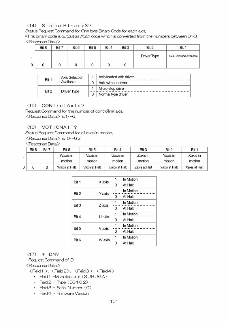
151
(14) StatusBinary3?
Status Request Command for One byte Binary Code for each axis.
*This binary code is output as ASCII code which is converted from the numbers between 0~3.
<Response Data>
Bit 8 Bit 7 Bit 6 Bit 5 Bit 4 Bit 3 Bit 2 Bit 1 1
Driver Type Axis Selection Available
0 0 0 0 0 0 0
1 Axis loaded with driver Bit 1 Axis Selection
Available 0 Axix without driver 1 Micro-step driver
Bit 2 Driver Type 0 Normal type driver
(15) CONTrolAxis?
Request Command for the number of controlling axis.
<Response Data> is1~6.
(16) MOTIONAll?
Status Request Command for all axes in motion.
<Response Data> is 0~63.
<Response Data>
Bit 8 Bit 7 Bit 6 Bit 5 Bit 4 Bit 3 Bit 2 Bit 1 1
Waxis in motion
Vaxis in motion
Uaxis in motion
Zaxis in motion
Yaxis in motion
Xaxis in motion
0 0 0 Waxis at Halt Vaxis at Halt Uaxis at Halt Zaxis at Halt Yaxis at Halt Xaxis at Halt
1 In Motion Bit 1 X axis
0 At Halt 1 In Motion
Bit 2 Y axis 0 At Halt 1 In Motion
Bit 3 Z axis 0 At Halt 1 In Motion
Bit 4 U axis 0 At Halt 1 In Motion
Bit 5 V axis 0 At Halt 1 In Motion
Bit 6 W axis0 At Halt
(17) *IDN?
Request Command of ID
<Response Data>
<Field1>,<Field2>,<Field3>,<Field4>
・ Field1…Manufacturer(SURUGA)
・ Field2… Type(DS102)
・ Field3… Serial Number(0)
・ Field4… Firmware Version
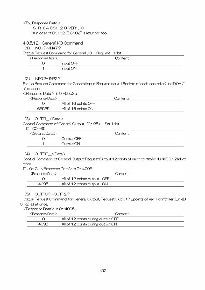
152
<Ex.: Response Data>
SURUGA, DS102, 0, VER1.00
※In case of DS112, “DS102” is returned too.
4.3.5.12 General I/O Command
(1) IN00?~IN47?
Status Request Command for General I/O Request 1/bit
<Response Data> Content
0 Input OFF
1 Input ON
(2) INP0?~INP2?
Status Request Command for General Input. Request Input 16points of each controller(LinkID0~2)
all at once.
<Response Data> is 0~65535.
<Response Data> Contents
0 All of 16 points OFF
65535 All of 16 points ON
(3) OUT□_<Data>
Control Command of General Output.(0~35) Set 1/bit
□:00~35.
<Setting Data> Content
0 Output OFF
1 Output ON
(4) OUTP□_<Data>
Control Command of General Output. Request Output 12points of each controller (LinkID0~2)all at
once.
□:0~2、<Response Data> is 0~4095.
<Response Data> Content
0 All of 12 points output OFF
4095 All of 12 points output ON
(5) OUTP0?~OUTP2?
Status Request Command for General Output. Request Output 12points of each controller (LinkID
0~2) all at once.
<Response Data> is 0~4095.
<Response Data> Content
0 All of 12 points during output OFF
4095 All of 12 points during output ON
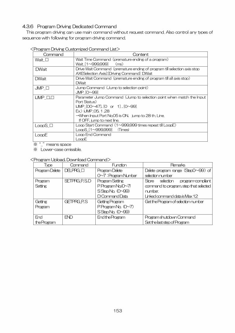
153
4.3.6 Program Driving Dedicated Command
This program driving can use main command without request command. Also control any types of
sequence with following for program driving command.
<Program Driving Customized Command List>
Command Content
Wait_□ Wait Time Command(premature ending of a program)
Wait_[1~999,999] (ms)
:DWait Drive Wait Command(premature ending of program till selection axis stop
AXI[Selection Axis]:[Driving Command] :DWait
DWait Drive Wait Command(premature ending of program till all axis stop)
DWait
JMP_□ Jump Command(Jump to selection point)
JMP_[0~99]
IJMP_□,□ Parameter Jump Command(Jump to selection point when match the Input
Port Status)
IJMP_[00~47], [0 or 1] , [0~99]
Ex.)IJMP_05, 1 ,28
→When Input Port No.05 is ON, jump to 28 th. Line.
If OFF, jump to next line.
LoopS_□ Loop Start Command(1~999,999 times repeat till LoopE)
LoopS_[1~999,999] (Times)
LoopE Loop End Command
LoopE
※“_”means space
※ Lower-case omissible.
<Program Upload, Download Command>
Type Command Function Remarks
Program Delete DELPRG_□ Program Delete
0~7:Program Number
Delete program range(Step0~99)of
selection number
Program
Setting
SETPRG_P, S, D Program Setting
P: Program No,(0~7)
S: Step No.(0~99)
D: Command Data
Store selection program-compliant
command to program, step that selected
number.
Linked command data is Max 12
Getting
Program
GETPRG_P, S Getting Program
P: Program No.(0~7)
S: Step No.(0~99)
Get the Program of selection number
End
the Program
END End the Program Program shutdown Command
Set the last step of Program
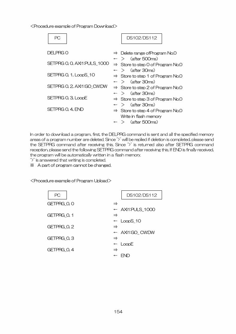
154
<Procedure example of Program Download>
In order to download a program, first, the DELPRG command is sent and all the specified memory
areas of a program number are deleted. Since ">" will be replied if deletion is completed, please send
the SETPRG command after receiving this. Since ">" is returned also after SETPRG command
reception, please send the following SETPRG command after receiving this. If END is finally received,
the program will be automatically written in a flash memory.
">" is answered that writing is completed.
※ A part of program cannot be changed.
<Procedure example of Program Upload>
GETPRG_0, 0
GETPRG_0, 1
GETPRG_0, 2
GETPRG_0, 3
GETPRG_0, 4
⇒
← AXI1:PULS_1000
⇒
← LoopS_10
⇒
← AXI1:GO_ CW:DW
⇒
← LoopE
⇒
← END
PC DS102/DS112
DELPRG 0
SETPRG 0, 0, AXI1:PULS_1000
SETPRG 0, 1, LoopS_10
SETPRG 0, 2, AXI1:GO_CW:DW
SETPRG 0, 3, LoopE
SETPRG 0, 4, END
⇒ Delete range ofProgram No.0
← > (after 500ms)
⇒ Store to step 0 of Program No.0
← > (after 30ms)
⇒ Store to step 1 of Program No.0
← > (after 30ms)
⇒ Store to step 2 of Program No.0
← > (after 30ms)
⇒ Store to step 3 of Program No.0
← > (after 30ms)
⇒ Store to step 4 of Program No.0
Write in flash memory
← > (after 500ms)
PC DS102/DS112
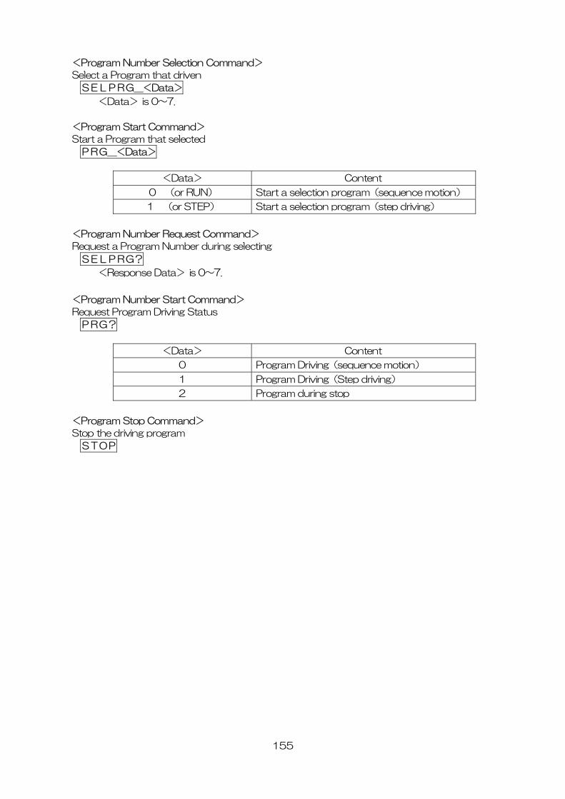
155
<Program Number Selection Command>
Select a Program that driven
SELPRG_<Data>
<Data> is 0~7.
<Program Start Command>
Start a Program that selected
PRG_<Data>
<Data> Content
0 (or RUN) Start a selection program(sequence motion)
1 (or STEP) Start a selection program(step driving)
<Program Number Request Command>
Request a Program Number during selecting
SELPRG?
<Response Data> is 0~7.
<Program Number Start Command>
Request Program Driving Status
PRG?
<Data> Content
0 Program Driving(sequence motion)
1 Program Driving(Step driving)
2 Program during stop
<Program Stop Command>
Stop the driving program
STOP

156
4.3.7 Error Code
In case of command response function is effect, if communication command doesn’t match, send
back the following code by ASCII.
Code Function Cause
E00 Stage is not connected
Sensor logic setting error
Driving Command starts to stage is unconnected axis.
E01 In Motion Send a driving type command to motor in motion, or start the command
during program driving, teaching or setting handy terminal
E02 Limit detecting Already had a limit detecting at the start
E03 Emergency detecting Start Driving Command when input the emergency signal.
E20 Command rule error Error of command documents
E21 Error of unsent delimiter No delimiter(CR) or incorrect
E22 Setting Range Error Over setting range of coordinate or setting value
E40 Communication Error Abnormal communication line (included Link)
E41 Error of write in flash memory Can’t store due to flash memory trouble or lifetime
※ When Command Response function is no effect, nothing return eventhough
communication command is unmatched.
【Setting DIP switch】
Set 7 th. of SW1
● Setting Command Response
7 Command response Enable /Disable
OFF Disable(Default)
ON Enable
※ OFF setting at the before shipping.
SW1
1 2 3 4 5 6 ON
7 8
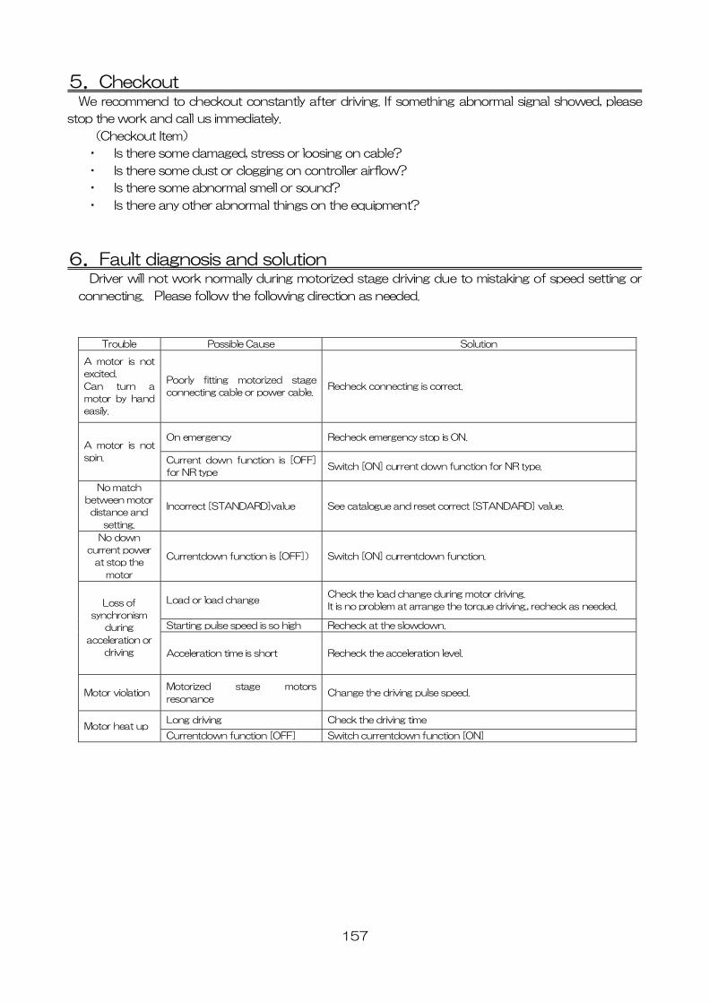
157
5.Checkout We recommend to checkout constantly after driving. If something abnormal signal showed, please
stop the work and call us immediately.
(Checkout Item)
・ Is there some damaged, stress or loosing on cable?
・ Is there some dust or clogging on controller airflow?
・ Is there some abnormal smell or sound?
・ Is there any other abnormal things on the equipment?
6.Fault diagnosis and solution Driver will not work normally during motorized stage driving due to mistaking of speed setting or
connecting. Please follow the following direction as needed.
Trouble Possible Cause Solution
A motor is not
excited.
Can turn a
motor by hand
easily.
Poorly fitting motorized stage
connecting cable or power cable.Recheck connecting is correct.
On emergency Recheck emergency stop is ON. A motor is not
spin. Current down function is [OFF]
for NR type Switch [ON] current down function for NR type.
No match
between motor
distance and
setting.
Incorrect [STANDARD]value See catalogue and reset correct [STANDARD] value.
No down
current power
at stop the
motor
Currentdown function is [OFF]) Switch [ON] currentdown function.
Load or load change Check the load change during motor driving.
It is no problem at arrange the torque driving., recheck as needed.
Starting pulse speed is so high Recheck at the slowdown.
Loss of
synchronism
during
acceleration or
driving Acceleration time is short Recheck the acceleration level.
Motor violation Motorized stage motors
resonance Change the driving pulse speed.
Long driving Check the driving time Motor heat up
Currentdown function [OFF] Switch currentdown function [ON]
158
7.Warranty & Customer Service ●Warranty
At time of contacting Suruga Seiki or our distributor in your area, please refer to the serial number
of product that is indicated on the side of product or enclosed warranty or quality assurance cetificate.
Suruga Seiki will refer to the date of purchase and registration according to the serial number. The
warranty period is one year from the time of purchase.
The following conditions are not covered by the warranty.
-Failure to use the product properly as explained in the instruction manual, damage or injury
caused by repair or modification made by a person other than a qualified personnel of
Suruga Seiki.
-Damage caused by breakage during shipping or transportation or faulty handling.
-Damage due to fire, gas, sea and sea wind, wrong electrical or battery voltage, earthquake,
thunder, flood and wind, and any other acts of nature.
-Damage or injury due to not following the proper procedures as indicated in the instruction
manuals, not adhering to the caution warnings as indicated in the instruction manuals.
●Repair Service
Please contact your local Suruga Seiki distributor for service if the problem will persists.
《During Warranty Period》
Suruga Seiki will repair breakage caused under proper use following operation manuals for free
of charge. Those repairs except mentioned above will be charged.
《After Warranty Period》
When repairing may maintain functions of a product, we can repair the product as charged
service.
●Repairable Period
Repairable Period and Repair Parts
Replacement and repair parts of controller are guaranteed for one year after closing of
production. This period is the repairable period. However, please contact your local Suruga
Seiki distributor for repairs and replacement parts even after the repairable period in case that
repair may be still available.
<Regarding controller’s breakage, Suruga Seiki will not be responsible for anything but free repair
service based on this warranty.>
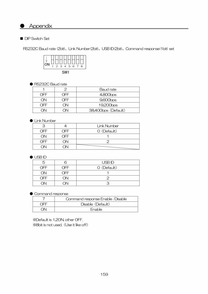
159
● Appendix
■ DIP Switch Set
RS232C Baud rate (2bit)、Link Number(2bit)、USB ID(2bit)、Command response(1bit) set
● RS232C Baud rate
1 2 Baud rate
OFF OFF 4,800bps
ON OFF 9,600bps
OFF ON 19,200bps
ON ON 38,400bps(Default)
● Link Number
3 4 Link Number
OFF OFF 0(Default)
ON OFF 1
OFF ON 2
ON ON
● USB ID
5 6 USB ID
OFF OFF 0(Default)
ON OFF 1
OFF ON 2
ON ON 3
● Command response
7 Command response Enable /Disable
OFF Disable(Default)
ON Enable
※Default is 1,2ON, other OFF.
※8bit is not used.(Use it like off)
SW1
1 2 3 4 5 6 ON
7 8
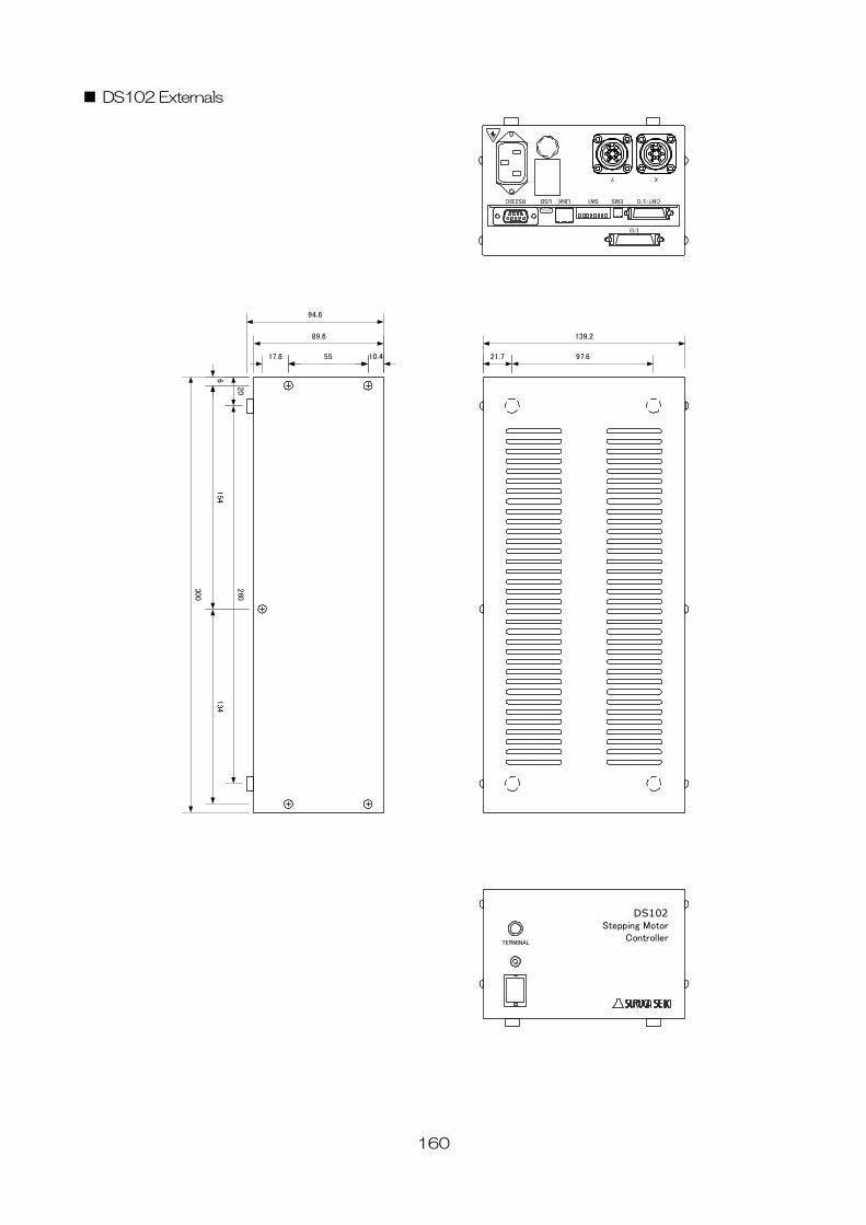
160
■ DS102 Externals
139.2
300
TERMINAL
DS102Stepping Motor
Controller
XY
I/O
CNT-I/OEMSSW1LINKUSBRS232C
89.6
6
10.45517.8
154
134
20
260
94.6
21.7 97.6
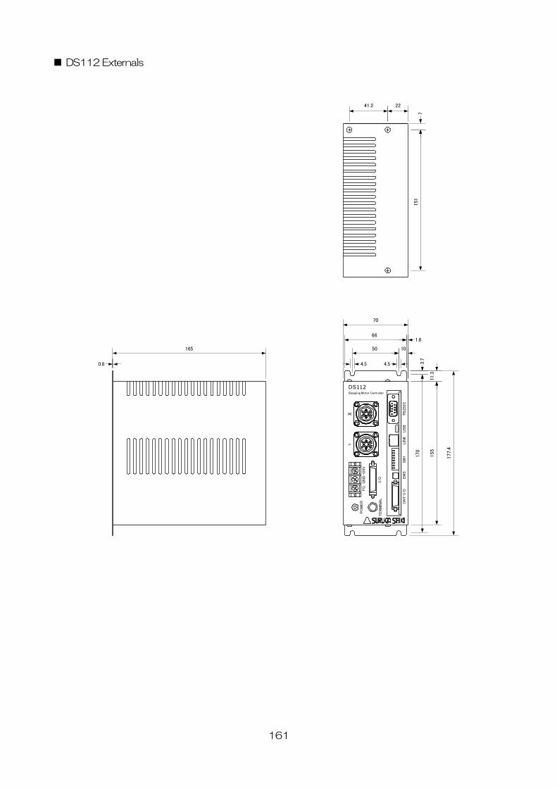
161
■ DS112 Externals
155
70
XY
TER
MIN
AL
PO
WER
+24V
CN
T-I
/OEM
SSW
1LIN
KU
SB
RS
232C
DS112Stepping Motor Controller
GN
DFG
I/O
177.4
11.3
1.6
3.7
170
10
4.5 4.5
50
66
165
7
0.8
2241.2
151
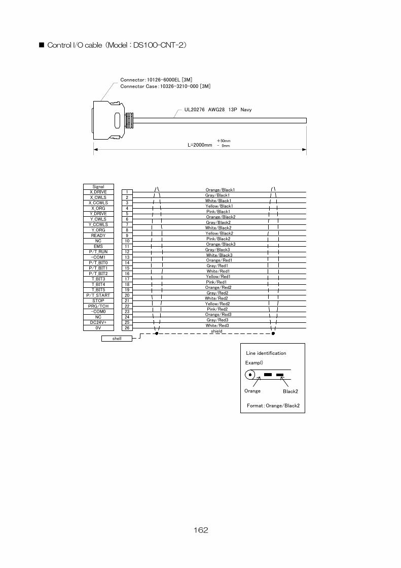
162
■ Control I/O cable(Model:DS100-CNT-2)
L=2000mm+50mm- 0mm
Connector:10126-6000EL [3M]Connector Case:10326-3210-000 [3M]
UL20276 AWG28 13P Navy
Orange/Black1Gray/Black1White/Black1Yellow/Black1Pink/Black1Orange/Black2Gray/Black2White/Black2Yellow/Black2Pink/Black2Orange/Black3Gray/Black3White/Black3Orange/Red1Gray/Red1White/Red1Yellow/Red1Pink/Red1Orange/Red2Gray/Red2
White/Red2
1234567891011121314151617181920212223242526
X_DRIVEX_CWLS
X_CCWLSX_ORG
Y_DRIVEY_CWLS
Y_CCWLSY_ORGREADY
NCEMS
P/T_RUN-COM1
P/T_BIT0P/T_BIT1P/T_BIT2T_BIT3T_BIT4T_BIT5
P/T_STARTSTOP
PRG/TCH-COM0
NCDC24V+
0V
Signal
Yellow/Red2Pink/Red2
Orange/Red3Gray/Red3White/Red3
Line identification
Exampl)
Orange Black2
Format:Orange/Black2
shell
shield
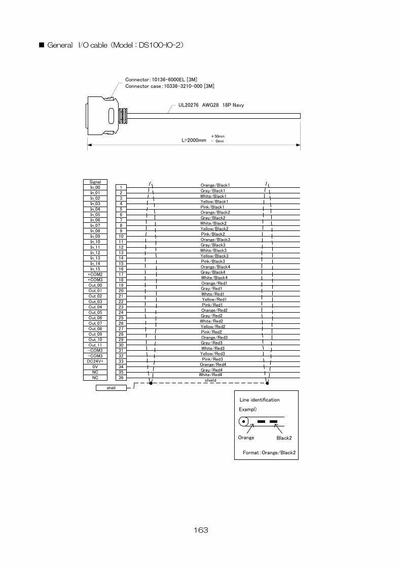
163
■ General I/O cable(Model:DS100-IO-2)
123456789101112131415161718192021222324252627282930313233343536
L=2000mm+50mm- 0mm
Connector:10136-6000EL [3M]Connector case:10336-3210-000 [3M]
UL20276 AWG28 18P Navy
Orange/Black1Gray/Black1White/Black1Yellow/Black1Pink/Black1Orange/Black2Gray/Black2White/Black2Yellow/Black2Pink/Black2Orange/Black3Gray/Black3White/Black3Yellow/Black3Pink/Black3Orange/Black4Gray/Black4White/Black4Orange/Red1Gray/Red1White/Red1Yellow/Red1Pink/Red1Orange/Red2Gray/Red2White/Red2Yellow/Red2Pink/Red2Orange/Red3Gray/Red3White/Red3Yellow/Red3Pink/Red3
Orange/Red4Gray/Red4
White/Red4
In_00In_01In_02In_03In_04In_05In_06In_07In_08In_09In_10In_11In_12In_13In_14In_15
+COM2+COM3Out_00Out_01Out_02Out_03Out_04Out_05Out_06Out_07Out_08Out_09Out_10Out_11-COM3-COM3DC24V+
0VNCNC
Signal
Line identification
Exampl)
Orange Black2
Format:Orange/Black2
shell
shield
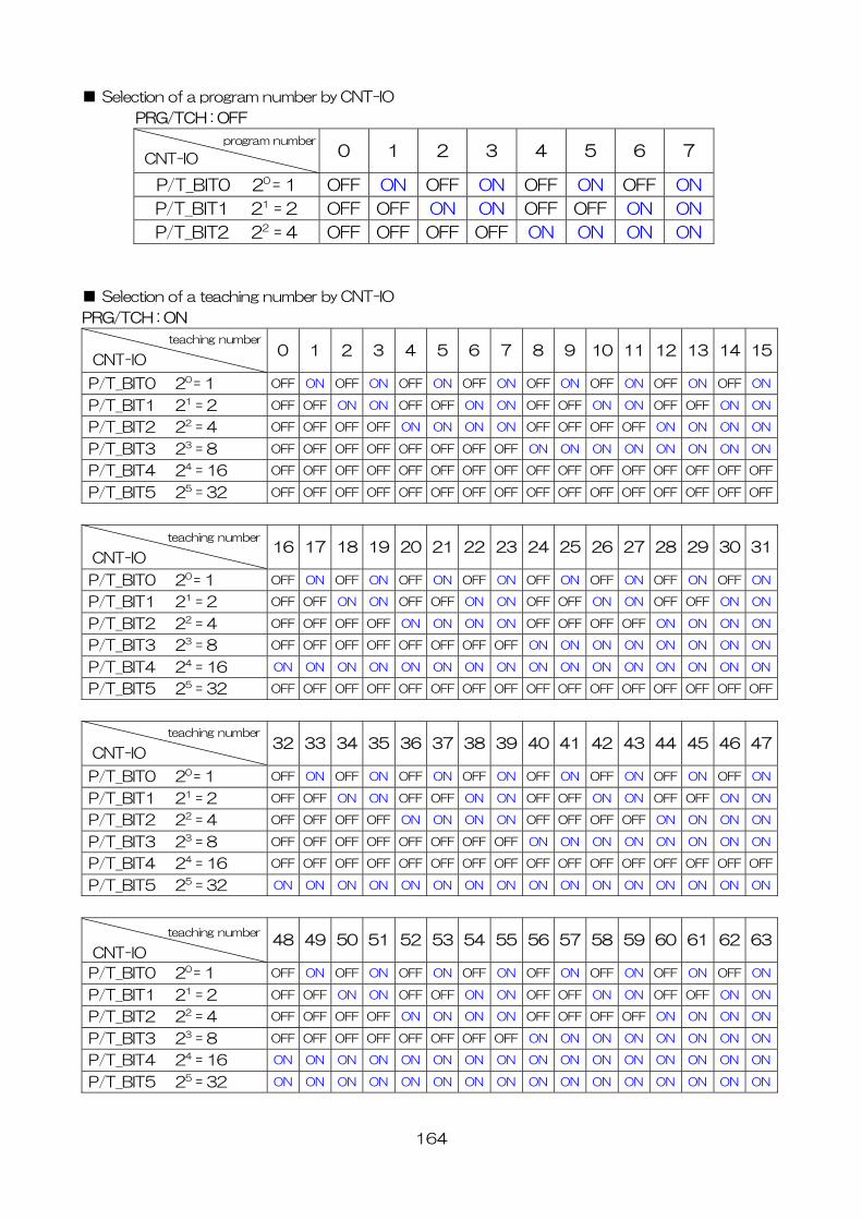
■ Selection of a program number by CNT-IO
PRG/TCH : OFF
0 1 2 3 4 5 6 7
P/T_BIT0 20 = 1 OFF ON OFF ON OFF ON OFF ON
P/T_BIT1 21 = 2 OFF OFF ON ON OFF OFF ON ON
P/T_BIT2 22 = 4 OFF OFF OFF OFF ON ON ON ON
■ Selection of a teaching number by CNT-IO
PRG/TCH : ON
0 1 2 3 4 5 6 7 8 9 10 11 12 13 14 15
program number
CNT-IO
teaching number
CNT-IOP/T_BIT0 20 = 1 OFF ON OFF ON OFF ON OFF ON OFF ON OFF ON OFF ON OFF ON
P/T_BIT1 21 = 2 OFF OFF ON ON OFF OFF ON ON OFF OFF ON ON OFF OFF ON ON
P/T_BIT2 22 = 4 OFF OFF OFF OFF ON ON ON ON OFF OFF OFF OFF ON ON ON ON
P/T_BIT3 23 = 8 OFF OFF OFF OFF OFF OFF OFF OFF ON ON ON ON ON ON ON ON
P/T_BIT4 24 = 16 OFF OFF OFF OFF OFF OFF OFF OFF OFF OFF OFF OFF OFF OFF OFF OFF
P/T_BIT5 25 = 32 OFF OFF OFF OFF OFF OFF OFF OFF OFF OFF OFF OFF OFF OFF OFF OFF
16 17 18 19 20 21 22 23 24 25 26 27 28 29 30 31
teaching number
O
CNT-IP/T_BIT0 20 = 1 OFF ON OFF ON OFF ON OFF ON OFF ON OFF ON OFF ON OFF ON
P/T_BIT1 21 = 2 OFF OFF ON ON OFF OFF ON ON OFF OFF ON ON OFF OFF ON ON
P/T_BIT2 22 = 4 OFF OFF OFF OFF ON ON ON ON OFF OFF OFF OFF ON ON ON ON
P/T_BIT3 23 = 8 OFF OFF OFF OFF OFF OFF OFF OFF ON ON ON ON ON ON ON ON
P/T_BIT4 24 = 16 ON ON ON ON ON ON ON ON ON ON ON ON ON ON ON ON
P/T_BIT5 25 = 32 OFF OFF OFF OFF OFF OFF OFF OFF OFF OFF OFF OFF OFF OFF OFF OFF
32 33 34 35 36 37 38 39 40 41 42 43 44 45 46 47
teaching number
O
CNT-IP/T_BIT0 20 = 1 OFF ON OFF ON OFF ON OFF ON OFF ON OFF ON OFF ON OFF ON
P/T_BIT1 21 = 2 OFF OFF ON ON OFF OFF ON ON OFF OFF ON ON OFF OFF ON ON
P/T_BIT2 22 = 4 OFF OFF OFF OFF ON ON ON ON OFF OFF OFF OFF ON ON ON ON
P/T_BIT3 23 = 8 OFF OFF OFF OFF OFF OFF OFF OFF ON ON ON ON ON ON ON ON
P/T_BIT4 24 = 16 OFF OFF OFF OFF OFF OFF OFF OFF OFF OFF OFF OFF OFF OFF OFF OFF
P/T_BIT5 25 = 32 ON ON ON ON ON ON ON ON ON ON ON ON ON ON ON ON
48 49 50 51 52 53 54 55 56 57 58 59 60 61 62 63
teaching number
CNT-IO164
P/T_BIT0 20 = 1 OFF ON OFF ON OFF ON OFF ON OFF ON OFF ON OFF ON OFF ON
P/T_BIT1 21 = 2 OFF OFF ON ON OFF OFF ON ON OFF OFF ON ON OFF OFF ON ON
P/T_BIT2 22 = 4 OFF OFF OFF OFF ON ON ON ON OFF OFF OFF OFF ON ON ON ON
P/T_BIT3 23 = 8 OFF OFF OFF OFF OFF OFF OFF OFF ON ON ON ON ON ON ON ON
P/T_BIT4 24 = 16 ON ON ON ON ON ON ON ON ON ON ON ON ON ON ON ON
P/T_BIT5 25 = 32 ON ON ON ON ON ON ON ON ON ON ON ON ON ON ON ON
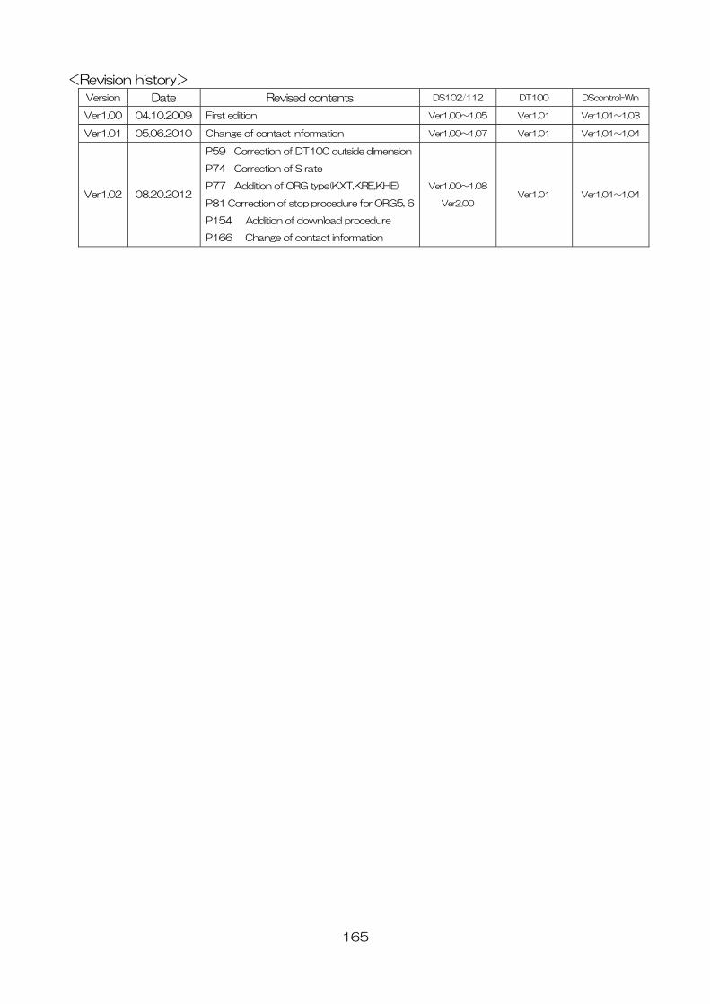
165
<Revision history>
Version Date Revised contents DS102/112 DT100 DScontrol-Win
Ver1.00 04.10.2009 First edition Ver1.00~1.05 Ver1.01 Ver1.01~1.03
Ver1.01 05.06.2010 Change of contact information Ver1.00~1.07 Ver1.01 Ver1.01~1.04
Ver1.02 08.20.2012
P59 Correction of DT100 outside dimension
P74 Correction of S rate
P77 Addition of ORG type(KXT,KRE,KHE)
P81 Correction of stop procedure for ORG5, 6
P154 Addition of download procedure
P166 Change of contact information
Ver1.00~1.08
Ver2.00 Ver1.01 Ver1.01~1.04
166
<CONTACT INFORMATION>
MISUMI group
SURUGA SEIKI Co., Ltd. OST division
TEL: +81-3-6711-5014
FAX: +81-3-6711-5021
Operation hours (Japan time) Monday to Friday: 9:00-12:00/13:00-18:00 Saturdays, Sundays, National holidays and New year period: CLOSED
HHThttp://www.suruga-ost.com/THH
E-mail [email protected]
Tokyo Branch Office
3F Konan YK Bldg., 2-4-12, Konan, Minato-ku, Tokyo,
108-0075 JAPAN
TEL +81-3-6711-5011 FAX +81-3-6711-5018
Head Office & Main Factory
505, Nanatsushinya, Shimizu-ku, Shizuoka-city, Shizuoka,
424-8566 JAPAN
SURUGA SEIKI SALES & TRADING (SHANGHAI) Co., Ltd.
Head Office / Shanghai Office
Room 2503, No.580 Nanjing Xi Road, Jing An District,
Shanghai, China
TEL +86-21-62870630 FAX +86-21-62870639
HHThttp://www.suruga-g.cn/THH
E-mail [email protected]