Embed Size (px)
Citation preview
TITLE: 4X600 MW OPJ STPP PHASE-III,
RAIGARH
SCOPE OF WORK
SPECIFICATION NO. PE-TS-329-616-C001
VOLUME - IIB
SECTION “A”
REV. 00
SHEET 1 OF 2
JINDAL POWER LIMITED
4X600MW OPJ STPP, PHASE-III
RAIGARH
VOLUME: II B
SECTION - A SCOPE OF WORK
SPECIFICATION NO. PE-TS-329-616-C001
Bharat Heavy Electricals Limited Project Engineering Management
Power Sector, PPEI Building Noida-201 301
SECTION-A

TITLE: 4X600 MW OPJ STPP PHASE-III,
RAIGARH
SCOPE OF WORK
SPECIFICATION NO. PE-TS-329-616-C001
VOLUME - IIB
SECTION “A”
REV. 00
SHEET 2 OF 2
Scope of Work
1.0 The scope of work consists of the following parts:
A/ Structural Steel works for Mill & Bunker Building including Bunkers.
2.0 The works to be performed under this contract consist of providing all labour,
supervision, material (other than BHEL Supply), scaffolding, construction equipment, tools and plants, temporary works, supplies including POL, transportation and all incidental items not shown or specified but reasonably implied or necessary for the proper completion of work in all respects & preparation of fabrication drawings (Contractor to engage an independent agency with the approval of BHEL for checking of fabrication drawings prepared by contractor before submitting them to BHEL for approval). Works shall only be carried out with approved structural fabrication drawings (provided by BHEL).
3.0 Supply (other than BHEL Supply), Fabrication and erection of structural steel work
involving rolled section, sections fabricated out of plates, chequered / electroforged
gratings, hand rails, primer and final painting for all steel structural works including
supply of erection bolts if any, low hydrogen quality electrodes for welding, non
destructive testing etc. Complete as per Quality Plan/Customer requirements.
4.0 All the works areas shall be adequately flood lighted to the satisfaction of the Engineer-in-Charge when the work is in progress during the night shifts.
5.0 The unit rates shall include all material equipment, fixtures, labour construction plant,
temporary works and everything whether of permanent or temporary nature necessary for the completion of job in all respects.
6.0 The unit rates quoted for various items of B.O.Q shall include all the stipulations
mentioned in Section C and technical specifications under Section D and nothing extra over B.O.Q rates shall be payable.
7.0 Design/Fabrication drawings showing enough details for the construction as per the
Specification shall be furnished to the contractor in a phased manner as far as possible.
SECTION-A
TITLE: 4X600 MW OPJ STPP, PHASE-III
RAIGARH
PROJECT INFORMATION
SPECIFICATION NO. PE-TS-329-616-C001
VOLUME - IIB
SECTION “B”
REV. 00
SHEET 1 OF 2
JINDAL POWER LIMITED
4X600MW OPJ STPP, PHASE-III
RAIGARH
VOLUME: II B
SECTION - B
PROJECT INFORMATION
SPECIFICATION NO. PE-TS-329-616-C001
Bharat Heavy Electricals Limited Project Engineering Management
Power Sector, PPEI Building Noida - 201 301
TITLE: 4X600 MW OPJ STPP, PHASE-III
RAIGARH
PROJECT INFORMATION
SPECIFICATION NO. PE-TS-329-616-C001
VOLUME - IIB
SECTION “B”
REV. 00
SHEET 2 OF 2
INTRODUCTION
4X600 MW OPJ STPP, PHASE-III is being setting up by Jindal Power Limited (JPL) near the existing 4X250 MW Thermal Power Plant at Raigarh in the state of Chhattisgarh. The
plant will have an ultimate capacity of 2400MW.
The site is located near Village, Tamnar in Raigarh District of Chhattisgarh State. Contractor is advised to visit the site and appraise himself about the conditions of the site and infrastructure available in the area for fulfilling their commitment under the contract.
APPROACH TO SITE
The site is approachable from Raigarh by the State Highway which branches off at Punjipathra, about 12 Km from the site and 34 Km from Raigarh Town. The nearest broad gauge rail Link is at Raigarh, which is about 35 Km.
TITLE: 4X600 MW OPJ STPP, PHASE-III
RAIGARH
SPECIFIC TECHNICAL REQUIREMENT FOR
GENERAL CIVIL WORKS
SPECIFICATION NO. PE-TS-329-616-C001
VOLUME - IIB
SECTION “C”
REV. 00
SHEET 1 OF 9
JINDAL POWER LIMITED
4X600MW OPJ STPP, PHASE-III
RAIGARH
VOLUME: II B
SECTION - C
SPECIFIC TECHNICAL REQUIREMENTS
FOR STRUCTURAL WORKS
SPECIFICATION NO. PE-TS-329-616-C001
Bharat Heavy Electricals Limited Project Engineering Management
Power Sector, PPEI Building Noida -201 301
SECTION-C
TITLE: 4X600 MW OPJ STPP, PHASE-III
RAIGARH
SPECIFIC TECHNICAL REQUIREMENT FOR
GENERAL CIVIL WORKS
SPECIFICATION NO. PE-TS-329-616-C001
VOLUME - IIB
SECTION “C”
REV. 00
SHEET 2 OF 9
SPECIFIC TECHNICAL REQUIREMENTS
1. GENERAL
Section-C covers specific technical requirements of contract and should be read in conjunction with BOQ, Section-D and other sections of the contract. In case of any conflict between the contents of BOQ and Section-C/Section-D, BOQ will prevail over Section-C/Section-D. In case of any conflict between Section-C and Section-D, Section-C will prevail over Section-D.
2. STEEL STRUCTURAL WORKS
Structural Steel shall conform to IS: 2062 Grade - A for rolled steel members or plates up to 20 mm thickness. For plates above 20 mm thickness and welded construction steel conforming to IS: 2062 Grade - B (killed and normalized) shall be used. Steel shall be procured from JINDAL, SAIL or any other approved main
producer. The materials are preferably procured from M/s JINDAL STEEL as
per the MoU signed between BHEL and the concerned.
Chequered plate shall conform to IS: 3502 (latest) and minimum thickness of chequered plate for floorings, covers etc. shall be 6 mm O/P. All gratings shall be electroforged type. The surface shall be blast cleaned to near white metal surface (SA 2 ½) followed by two coats of epoxy resin based Zinc Phosphate Primer and two coats of approved color enameled finish paint. Staircase treads shall be provided with anti-skid nosing.
For hand railings GI pipe of medium grade conforming to IS: 1239 and galvanizing shall be smooth confirming to IS: 2633 shall be used. Hand railing shall be flush welded construction, ground smooth using 32 mm Nominal Bore of 42.2 mm outside diameter pipe, provided with double rail and pipe posts. Top rail shall be provided at
1000 mm above platform or as approved and pipe posts spaced not more than 1500 mm center to center. Hand rails post and rails shall have one coats of epoxy resin based Zinc Phosphate Primer. Final painting shall be same as given for painting on structures.
2.1. CONNECTIONS
Shop connections shall be all welded type and field connections shall generally be bolted type unless specified otherwise. Field bolts, wherever provided, shall be high tensile friction grip bolt of 20 mm dia. or of higher diameter and of property class 8.8 (minimum) as per IS:1367 (latest) for all major connections. All bolts, nuts and washers shall be procured from M/S Guest Keen Whalliams (G.K.W) or any other equivalent source approved by BHEL in future. The bolted joints shall be designed for friction type connection and the H.T. bolts shall be tightened to develop the
SECTION-C
TITLE: 4X600 MW OPJ STPP, PHASE-III
RAIGARH
SPECIFIC TECHNICAL REQUIREMENT FOR
GENERAL CIVIL WORKS
SPECIFICATION NO. PE-TS-329-616-C001
VOLUME - IIB
SECTION “C”
REV. 00
SHEET 3 OF 9
required pre-tension during their installation. However, the nominal connections in the field like girts, stairs, wall beams shall be done by means of M.S. black bolts, conforming to IS:1363 unless specified otherwise.
Welding shall be done in accordance with the recommendation of IS:816 - “Code of Practice for use of metal arc welding for general construction in mild steel” and IS:9595 - “Recommendation for Metal arc welding of Carbon and Carbon Manganese Steels”. Submerged arc welding process shall be used for welding longitudinal fillet welds (connecting flanges with web) and longitudinal/transverse butt joints for fabrication of columns, framing beams, crane girders & and all other built up members unless manual arc welding is specifically required . All electrodes, flux, bare wire etc shall be procured from BHEL approved manufacturers, viz. Advani- Oerlikon, ESAB, D&H or any other equivalent approved source. All butt welds in beams, girders & columns shall be of full penetration. All butt welds shall be radio- graphically or ultrasonically tested as per relevant IS codes and standard practice. The bare wire electrodes for submerged arc welding shall conform to IS:7280. The combination of wire and flux shall satisfy requirement of IS: 3613. Flux and wire combination for submerged Arc welding of Structural steel shall be as follows : Filler wire shall be Automelt Gr-C wire of classification AWS-A-5.17-EH14 and flux shall be of agglomerated type (Automelt Gr.-IV) of classification AWS-A-5.17- F7A2EH 14 of Advani-Oerlikon make.
Following connections shall be provided during erection :
1. Welded Connections :
i. Connection of „Secondary Beam‟ to „Main Beam‟. ii. Connection of „Vertical Bracing‟ to „Column‟. iii. Connection of „Brackets‟ to „column‟. iv. Connection of „Vertical Bracing‟ to „Horizontal Bracing‟. v. Connection of „Horizontal Bracing‟ to „Column‟.
vi. Connection of „Bracket for Spandrel (Wall) Beam‟ to „Column‟. vii. Connection of other secondary structures.
2. HSFG connection (Grade 8.8 bolts)
i. Connection of „Crane Girder‟ to „Column‟. ii. Splice of „Column‟ & Splice of „Transverse Frame Girders‟. iii. Connection between Crane Girders. iv. Connection of members where tension shall be in the fastener.
3. Bearing Type conection (H.T. bolts Grade 8.8)
i. All removable type connections. ii. Connection of „Purlins‟ to „Roof Truss‟.
SECTION-C

TITLE: 4X600 MW OPJ STPP, PHASE-III
RAIGARH
SPECIFIC TECHNICAL REQUIREMENT FOR
GENERAL CIVIL WORKS
SPECIFICATION NO. PE-TS-329-616-C001
VOLUME - IIB
SECTION “C”
REV. 00
SHEET 4 OF 9
4. M.S Bolts (Gr. 4.6)
i. Girts, Stairs, Wall beams.
5. Low Hydrogen Electrodes as approved by the Engineer shall invariably be used in the following cases :
i. For welding of all important joints such as Butt joints in Columns (flange or web), Butt joints in Main frame Beams (Flange or web) etc.
ii. For welding steel having thickness more than 20 mm. In case of fillet weld between two components, the thickness of the thicker part shall be considered as the limit for (ii)
Minimum preheat & inter pass temperatures for welding over 40mm to 63 mm
(thickness of the thicker part at the point of welding) shall be 66° C and for over 63
mm, it shall be 110° C. However, higher preheat & inter pass temperatures may be
required due to joint restraint etc and shall be followed as per approved welding
procedure.
Shop primer paint shall be two coats of epoxy resin based Zinc Phosphate Primer and shall conform to IS: 2074 in all respects. The surface preparation shall be done in accordance with IS: 1477 (Part I & II) - Code of Practice for finishing of Ferrous Metals in Buildings.
Stainless steel liner in the coal Bunkers shall be of grade AISI - 304 Finish Grade 2 B (Cold Rolled, Annealed & Pickled and Skin passed) and shall be provided on the inner faces of entire inclined portion of Hoppers and mouth of the Hoppers, without allowing any projections in coal flow path. The electrode classification as per AWS shall be as follows :
i/ For welding of stainless steel to stainless steel : E308L ii/ For welding of stainless steel to mild steel : E309 Design Of Connections
i/ Fabrication drawings shall be prepared according to the provision of IS:800, IS:816, IS:9595, IS:1367 and IS:9178.
ii/ Connection of vertical bracings with connecting members and diagonals of truss members shall be designed for full tensile capacity of the bracings.
iii/ Size of fillet weld for flange to web connection for built up section shall be as follows :
SECTION-C
TITLE: 4X600 MW OPJ STPP, PHASE-III
RAIGARH
SPECIFIC TECHNICAL REQUIREMENT FOR
GENERAL CIVIL WORKS
SPECIFICATION NO. PE-TS-329-616-C001
VOLUME - IIB
SECTION “C”
REV. 00
SHEET 5 OF 9
a. Full shear capacity or actual shear which ever is more for box section. b. 80% of full shear capacity or actual shear (if indicated in drawings) or 0.5 times of the web thickness which ever is more. For I section Weld shall be double fillet.
c. All welds shall be continuous. The minimum size of the fillet weld shall be as per relevant IS code.
iv/ Shear connections shall be designed for 75% of section strength for rolled sections and 80% of section strength for built up section or rolled section with cover plates. Designed shear force shall be more than actual shear.
v/ Moment connections between beam and column shall be designed for 100% of moment capacity of the beam section.
vi/ All butt welds shall be full penetration butt welds. vii/ The connection between top flange & web of crane girder shall be full penetration butt weld & for bottom flange, connection may be fillet weld.
viii/Connection of base plate & gusset members with the columns shall be done considering that total load gets transferred through weld.
ix/ Splicing : All splicing work shall be full strength. Field splicing shall be done with web /flange cover plates. For, exceptional cases the field splicing shall be designed for 50% of load carried by the cover plates and remaining 50% load through full penetration butt weld. Shop splicing for all sections other than rolled shall be carried out by full penetration butt welds with no cover plates. Splicing for all rolled sections shall be carried out using web and flange cover plate.
2.2.Minimum Tests To Be Carried Out During Fabrication & Erection Of
Structural Steel
1. Steel
Ultrasonic test: plates above 25mm thickness shall be subjected to ultrasonic test as per ASTM-A435 or equivalent to check the presence of Lamination. 2. Fillet Weld
Dye penetration test : 5% of the total length, Dye penetration shall be carried out to the root run. 3. Butt Weld
Dye penetration test: 10% of the total length, Dye penetration test shall be carried out to the root run after back gouging. Radiography: Generally, splicing shall not be provided in tension flange of Bunker
Girders. Spot radiography shall be carried out on 100% joints in Tension zone &10%
SECTION-C

TITLE: 4X600 MW OPJ STPP, PHASE-III
RAIGARH
SPECIFIC TECHNICAL REQUIREMENT FOR
GENERAL CIVIL WORKS
SPECIFICATION NO. PE-TS-329-616-C001
VOLUME - IIB
SECTION “C”
REV. 00
SHEET 6 OF 9
joints in compression zone. Minimum 300 mm length shall be spot radio-graphed. When radiograph is not possible ultrasonic test shall be carried out after grinding the surface with prior approval of Engineer.
Ultrasonic Test: 10% of all other Butt welds shall be subject to spot radiographic test and the entire balance butt weld for ultrasonic test.
2.3. Painting of Structures
Material
Material shall be highest- grade products and shall be delivered to the site in original sealed containers, bearing brand name, manufactures name and colour shade with labels intact and seals unbroken. All materials shall be subject to the inspection, analysis and approved by the Engineer. For satisfactory results, it is desired that primer and finishing paints etc. are to be obtained by the bidder from the same manufacturer. All paints shall be subject to analysis from random sample taken at site from painters bucket, if so desired by the Engineer. Paint shall be stirred frequently to keep the pigment in suspension. Paint shall be ready mixed in original sealed container as packed by the paint manufacturer. Paints purchased for the work shall be brought to site in sealed container and shall be opened in the presence of the Engineer or his authorized representative.
Paints, primers etc required under this contract should be procured from approved manufacturers, viz. Berger Paints or any other equivalent sources approved by BHEL. In this regard, BHEL's decision is final and binding to the bidder. Each and every supply of primer, finishing paints, etc. should be accompanied by manufacturer‟s test certificates. At the time of procurement, the bidder should furnish all the procurement details to BHEL i.e., the type of material procured (primer, finishing paints etc.), quantity, source of procurement and shall submit all test certificates to BHEL. Bidder shall supply the paints in the exact colour / shade and type of finish of the paint, as per direction of BHEL and no extra payment shall be entertained by BHEL for the above.
All colors shall be approved by Engineer and tinting and matching shall be done to the satisfaction of the Engineer. In such case where samples are required they shall be executed in advance with the specified materials for the approval of the Engineer.
Primer (Epoxy Resin based Zinc Phosphate)
The primer shall be two coats of epoxy resin based Zinc Phosphate conforming to the requirements of IS: 2074 (Latest). Total DFT will be 100 microns in two layers of 50 micron each after fabrication and intermediate coat (or under coat). The primer should conform all the requirements of IS code and any deviation in any respect from IS code shall not be accepted. The paint should be approved by the Engineer. The surface preparation will be done in accordance with IS: 1477 (Part I & II) - Code of Practice for finishing of Ferrous Metals in Buildings.
SECTION-C
TITLE: 4X600 MW OPJ STPP, PHASE-III
RAIGARH
SPECIFIC TECHNICAL REQUIREMENT FOR
GENERAL CIVIL WORKS
SPECIFICATION NO. PE-TS-329-616-C001
VOLUME - IIB
SECTION “C”
REV. 00
SHEET 7 OF 9
Finishing Coats (Epoxy resin based paint pigmented with Titanium dioxide)
The finishing coat shall be of epoxy resin based paint pigmented with Titanium dioxide with min. DFT of 100 microns. Top coat shall consist of one coat of epoxy paint suitably pigmented of approved shade and colour with glossy finish and DFT of 75 microns. Additionally finishing coat of polyurethane of minimum DFT of 25 microns shall be provided. The paint shall give a smooth, hard, durable and glossy finish to all surfaces. Bidder shall supply the paints in the exact colour / shade and type of finish of the paint, as per direction of BHEL and no extra payment shall be entertained by BHEL for the above. The paint should conform to all the requirements of IS code and any deviation in any respect from IS code shall not be accepted. The paint should be approved by the Engineer.
Surface Preparation And Pre-Treatment (Structure) The surface preparation shall be done in accordance with IS: 1477- Part-I (latest)- “Code of Practice for painting of Ferrous Metals in Buildings: Part I (Pre- Treatment)” and as directed by the Engineer.
The metal surfaces shall be absolutely clean, dry and free from rust, scales, weld stag, flux deposit, soap films, wax, dirt, oil, grease, foreign matters like cement mortar, etc. and free from existing loose epoxy resin based Zinc Phosphate Primer and should be removed by means of wire brushes. Hand-scrappers, sand paper, emery cloth, emery papers, mechanical power tools, etc. or by other effective methods, Such as using solvent cleaning etc. where necessary and as per relevant IS codes and as directed by the Engineer. It should be remembered that perfectly clean surface is of great importance while dealing with die painting of ferrous metal. The surfaces should be carefully inspected and in cases, where the existing epoxy resin based Zinc Phosphate Primer is removed while cleaning the surfaces, the damaged portion should be thoroughly degreased by clean solvent swabbing, any corrosion products formed should be thoroughly removed and touched up with a coat of epoxy resin based Zinc Phosphate Primer. No extra payment shall be entertained by BHEL for the above. The actual painting work should be commenced only after obtaining clearance from the Engineer or his authorized representative regarding proper cleaning of the surface.
Application (Structure)
General
The painting work shall be carried out as per the colour scheme of BHEL or as per direction of the Engineer and the Bidder shall procure the paints accordingly. The method of application shall be as recommended by the manufacturer. In case of selection of special shades and colour (not available in standard shades) the Bidder
SECTION-C
TITLE: 4X600 MW OPJ STPP, PHASE-III
RAIGARH
SPECIFIC TECHNICAL REQUIREMENT FOR
GENERAL CIVIL WORKS
SPECIFICATION NO. PE-TS-329-616-C001
VOLUME - IIB
SECTION “C”
REV. 00
SHEET 8 OF 9
shall mix different shades and prepare test panels of minimum size 1 meter square as per instruction of the Engineer and obtain his approval prior of application of finishing paints.
Immediately after the preparation of the surface, and providing the touch of primer in the damaged area, the first coat of primer shall be provided by brush and ensuring a continuous film without „holidays'. After the first coat is hard dry, apply a second coat of primer so that a film perfectly free from 'holidays' is obtained. The second or subsequent finishing coats may be applied after the first finishing coat is hard dry and its gloss is knocked off by scuffing with a very fine cutting device. The surface should be dry, clean, and free from dust and moisture before subsequent coat is applied. it is essential to avoid corrosion or any other paint defects, which may result due to trapped of foreign materials in the paint film. All painting work shall be done in accordance with relevant I. S codes. Proper tools and implements shall be used. Scaffoldings, if used, shall be independent of the surface to be painted to avoid shade differences of the freshly repaired anchor holes. Painting shall be done by skilled labours in a workman like manner. All materials shall be applied evenly and thoroughly so as to be free of sags, runs, crawls or other defects. All coats shall be of proper consistency. In case of application by brush, no brush marks shall be visible. The brushes shall be clean
and in good condition before application of paint. The use, conditioning and maintenance of brushes for painting shall conform to the requirements given in Appendix-A of IS: 1477-part-II (latest).
No work shall be done under conditions that are unsuitable for production of good results. Application of paint which seals the surface to moisture shall. Only be done after the moisture on and below the surface has dried out. All coats shall be thoroughly dry before succeeding coat is applied. Coats of painting as specified are intended to cover surfaces perfectly. In case the surface is not covered properly by applying specified number of coats, further coats shall be applied by the Bidder to conform the paint as per acceptance criteria of this contract. Approval of the Engineer is to be obtained by the Bidder before application of each coat and no paint
shall be applied until the surface for painting has been accepted by the Engineer. The sequence of painting of the structural members shall be as per direction of BHEL and binding to the bidder. Finishing coats shall be of exact colour and shade as per approved samples and all finish shall be uniform in colour and texture. All parts of mouldings and ornaments shall be left clean and true to finish.
The surface, which has to be connected using friction type joint, shall not be applied with primer and finish paint before the completion of site connection. Similarly the portion of columns, which shall be encased in concrete, shall not be applied with primer and finish paint and shall be given a coat of neat cement wash.
SECTION-C
TITLE: 4X600 MW OPJ STPP, PHASE-III
RAIGARH
SPECIFIC TECHNICAL REQUIREMENT FOR
GENERAL CIVIL WORKS
SPECIFICATION NO. PE-TS-329-616-C001
VOLUME - IIB
SECTION “C”
REV. 00
SHEET 9 OF 9
Minimum Total Thickness Of Paint
Painting on ferrous metal surface shall be done as per IS: 1477(part I &II). The total dry film thickness of the finished paint should not be less than 100 microns, including whatever may be available dry film thickness of the existing epoxy resin based Zinc Phosphate Primer. The thickness shall be measured by alcometer or any other approved method as directed by the Engineer.
Structural steel work Tolerances
Tolerances on dimensions for fabrication of steel structures shall be according to IS: 7215.
Tolerances on dimensions for erection of steel structures shall be according to IS: 12843.
SECTION-C
TITLE:
TECHNICAL SPECIFICATION FOR
STRUCTURAL STEEL WORK
SPECIFICATION NO. PE-TS-329-616-C001
VOLUME - II B
SECTION - D
REV.NO. 0
SHEET 1 OF 2
JINDAL POWER LIMITED
4X600MW OPJ STPP, PHASE-III
RAIGARH
VOLUME: II B
SECTION - D
TECHNICAL SPECIFICATIONS
FOR
STRUCTURAL STEEL WORKS Bharat Heavy Electricals Limited
Project Engineering Management Power Sector, PPEI Building Noida-201 301
TITLE:
TECHNICAL SPECIFICATION FOR
STRUCTURAL STEEL WORK
SPECIFICATION NO. PE-TS-329-616-C001
VOLUME - II B
SECTION - D
REV.NO. 0
SHEET 2 OF 2
C O N T E N T S
VOLUME II B : TECHNICAL SPECIFICATIONS FOR STRUCTURAL STEEL
WORKS
SUB-SECTION NO. DESCRIPTION PAGES
D17 FABRICATION OF STRUCTURAL STEEL WORK 40
D18 ERECTION OF STRUCTURAL STEEL WORK 17
TITLE:
TECHNICAL SPECIFICATION FOR
FABRICATION OF STRUCTURAL
STEEL WORK
SPECIFICATION NO. PE-TS-329-616-C001
VOLUME - II B
SECTION - D SUB-SECTIO : D17
REV.NO. 0
SHEET 1 OF 40
JINDAL POWER LIMITED
4X600MW OPJ STPP, PHASE-III RAIGARH
VOLUME: II B SECTION - D
SUB-SECTION - D17
FABRICATION OF STRUCTURAL STEEL WORK
SPECIFICATION NO. PE-TS-329-616-C001
Bharat Heavy Electricals Limited Project Engineering Management
Power Sector, PPEI Building Noida -201 301
1

TITLE:
TECHNICAL SPECIFICATION FOR
FABRICATION OF STRUCTURAL
STEEL WORK
SPECIFICATION NO. PE-TS-329-616-C001
VOLUME - II B
SECTION - D SUB-SECTIO : D17
REV.NO. 0
SHEET 2 OF 40
C 0 N T E N T
CLAUSE NO. DESCRIPTION SHEET NO.
1.00.00 SCOPE 3
2.00.00 GENERAL 3
3.00.00 WORKMANSHIP 19
4.00.00 INSPECTION, TESTING, ACCEPTANCE CRITERIA AND DELIVERY 29
5.00.00 INFORMATION TO BE SUBMITTED 33
6.00.00 RATES AND MEASUREMENTS 34 2
TITLE:
TECHNICAL SPECIFICATION FOR
FABRICATION OF STRUCTURAL
STEEL WORK
SPECIFICATION NO. PE-TS-329-616-C001
VOLUME - II B
SECTION - D SUB-SECTIO : D17
REV.NO. 0
SHEET 3 OF 40
FABRICATION OF STRUCTURAL STEEL WORK 1.00.00 SCOPE
This specification covers supply, fabrication, testing, painting and delivery to
site of structural steelwork including supply of all consumable stores and
rivets, bolts, nuts, washers, electrodes and other materials required for
fabrication and field connections of all structural steelwork covered under the
scope of the contract.
2.00.00 GENERAL
2.01.00 Work to be provided for by the Contractor
The work to be provided for by the Contractor, unless otherwise specified elsewhere in the contract, shall include, but not be limited to the following
a) Preparation of complete detailed fabrication drawings and erection
marking drawings required for all the structures covered under the scope
of the contract based on the approved design drawings. As decided by the
Engineer, some or all of these detailed drawings will have to be submitted
for approval.
b) To submit revised design with calculations and detailed fabrication drawings in case any substitution of the designed sections are to be made.
c) To submit design calculations for joints and. connections developed by the
contractor along with detailed fabrication drawings, if required.
d) Furnish all materials, labour, tools and plant and all consumables required for fabrication and supply, all necessary rivets, bolts, nuts, washers, tie rods and welding electrodes for field connections,
e) Furnish shop painting of all fabricated steelwork as per requirements of this Specification.
f) Suitably mark, bundle, and pack for transport all fabricated materials.
g) Prepare and furnish detailed Bill of Materials, Drawing Office Dispatch
lists, Rivet and Bolt List and any other list of bought out items required in
connection with the fabrication and erection of the structural steelwork.
h) Insure, load and transport all fabricated steelwork field connection materials to site.
i) Maintain a fully equipped workshop at site for fabrication, modification
3
TITLE:
TECHNICAL SPECIFICATION FOR
FABRICATION OF STRUCTURAL
STEEL WORK
SPECIFICATION NO. PE-TS-329-616-C001
VOLUME - II B
SECTION - D SUB-SECTIO : D17
REV.NO. 0
SHEET 4 OF 40
and repairs of steelwork at site as may be required to complete the works in accordance with the Contract.
j) Specific technical requirements are given in Section -C of this document. In case of any contradiction between Section -D and Section -C ,
requirements as given in Section -C shall prevail.
2.02.00 Work by others
No work under this specification will be provided for by any agency other than the contractor, unless specifically mentioned otherwise elsewhere in the contract.
2.03.00 Codes and standards
All work under this specification shall, unless otherwise specified in the contract, conform to the requirements of the latest revision and/or
replacements of the following or any other relevant Indian Standard
specifications and codes of practice. In case any particular aspect of the work
is not specifically covered by any Indian Standard specification, any other
standard practice, as may be specified by the Engineer shall be followed:
IS : 800 - Code of Practice for general construction in steel.
IS : 806 - Code of practice for use of steel tubes in general building construction.
IS : 808 - Rolled steel beams, channels, and angle sections
IS : 813 - Scheme of symbols for welding
IS : 814 - Covered electrodes for metal arc welding of structural steel
IS : 815 - Classification and coding of covered electrodes for metal arc
welding of structural steels.
IS : 816 - Code of practice for use of metal arc welding for general
construction in mild steel IS : 817 - Code of practice for training and testing metal arc welders
IS : 818 - Code of practice for safety and health requirements in electric
and gas welding and cutting operations IS : 822 - Code of practice for inspection of welds
IS : 919 - Recommendations for limits and fits for Engineering
IS : 961 - Structural Steel (High Tensile)
4
TITLE:
TECHNICAL SPECIFICATION FOR
FABRICATION OF STRUCTURAL
STEEL WORK
SPECIFICATION NO. PE-TS-329-616-C001
VOLUME - II B
SECTION - D SUB-SECTIO : D17
REV.NO. 0
SHEET 5 OF 40
IS : 1148 - Rivet bars for structural purposes
IS : 1149 - High tensile rivet bars for structural purposes
IS : 1161 - Steel Tubes for structural purposes
IS : 1200 - Method of measurement of steelwork and ironwork (Part 8)
IS : 1239 - Mild Steel Tubes
IS : 1363 - Black hexagon bolts, nuts and lock nuts (dia. 6 to 30 mm) and black hexagon screws (dia 6 to 24 mm)
IS : 1364 - Precision and semi-precision hexagon bolts, screws, nuts and locknuts (dia, range 6 to 39 mm)
IS : 1367 - Technical supply conditions for threaded fasteners
IS : 1442 - Covered electrodes for the metal are welding of high tensile
structural steel
IS : 1477 - Code of practice for painting of ferrous metals in buildings Part -I Preheating
Part -II Painting
IS : 1608 - Method for tensile testing of steel products other than sheet
strip, wire and tube
IS : 1730 - Dimensions for steel plate, sheet, and strip for structural and general engineering purposes.
IS : 1731 - Dimensions for steel flats for structural and general engineering
purposes IS : 1852 - Rolling and cutting tolerances for hot-rolled steel products
IS : 1977 - Structural steel (ordinary quality) St-42-0
IS : 2062 - Steel for General Structural Purposes
IS : 2074 - Ready mixed paint, epoxy resin based Zinc Phosphate priming
IS : 2595 - Code of Practice for Radiographic Testing
IS : 2629 - Recommended practice for Hot-Dip Galvanizing of Iron and Steel
IS : 2633 - Method for testing uniformity of coating on Zinc Coated Articles
IS :2932 - Enamel, Synthetic, exterior, (a)Under Coating and (b) finishing
IS : 3757 - High strength structural bolts
5
TITLE:
TECHNICAL SPECIFICATION FOR
FABRICATION OF STRUCTURAL
STEEL WORK
SPECIFICATION NO. PE-TS-329-616-C001
VOLUME - II B
SECTION - D SUB-SECTIO : D17
REV.NO. 0
SHEET 6 OF 40
IS : 4759 - Specifications for Hot-Dip Zinc Coatings on Structural Steel
and other allied products
IS : 7205 - Safety Code for Erection of Structural Steelwork
IS : 7215 - Tolerances for fabrication of steel structures
IS : 7280 - Bare wire electrodes for submerged arc welding of structural
steels.
IS : 9595 - Recommendations for metal arc welding of carbon and carbon
manganese steels.
2.04.00 Conformity with Designs
The contractor shall design all connections, supply and fabricate all steelwork and furnish all connection materials in accordance with the approved drawings
and/or as instructed by the Engineer keeping in view the maximum Utilization of the available sizes and sections of steel materials. The methods of painting, marking, packing and delivery of all fabricated materials shall be in accordance with the provisions of the contract and/or as approved by the
Engineer. Provision of all relevant Indian Standard Specifications and Codes of Practice shall be followed unless otherwise specified in the contract.
2.05.00 Materials to be used
2.05.01 General
All steel materials required for the work will be supplied by the contractor unless otherwise specified elsewhere in the contract. The materials shall be
free from all imperfections, mill scales, slag intrusions, laminations, fittings,
rusts etc. that may impair their strength, durability, and appearance. All
materials shall be of tested quality only unless otherwise permitted by the
Engineer and/or Consultant. If desired by the Engineer, Test Certificates in
respect of each consignment shall be submitted in triplicate. Whenever the
materials are required to be used from unidentified stocks, if permitted by the
Engineer, a random sample shall be tested at an approved laboratory from
each lot of 50 tones or less of any particular section.
The arc welding electrodes shall be of approved reputed manufacture and
conforming to the relevant Indian Standard Codes of Practice and Specifications and shall be of heavily coated type and the thickness of the
coating shall be uniform and concentric. With each container of electrodes, the manufacturer shall furnish instructions giving recommended voltage and
amperage (Polarity in case of D.C. supply) for which the electrodes are suitable.
2.05.02 Steel
6
TITLE:
TECHNICAL SPECIFICATION FOR
FABRICATION OF STRUCTURAL
STEEL WORK
SPECIFICATION NO. PE-TS-329-616-C001
VOLUME - II B
SECTION - D SUB-SECTIO : D17
REV.NO. 0
SHEET 7 OF 40
All steel materials to be used in construction within the purview of this
specification shall comply with any of the following Indian Standard Specifications as may be applicable:
a) IS : 2062 - Steel for general structural purposes
b) IS : 961 - Structural steel High Tensile
c) IS : 1977 - Structural steel (Ordinary quality) St-42-0
In case of imported steel materials being used, these shall conform to specifications equivalent to any of the above as may be applicable.
2.05.03 Rivet Steel
All rivet steel used in construction within the purview of this Specification shall comply with one of the following Indian Standard Specifications as may be applicable:
a) IS : 1148 - Rivet Bars for structural purpose
b) IS : 1149 - High tensile rivet bars for structural purposes. Where high
tensile steel is specified for rivets, steps shall be taken to ensure
that the rivets are so manufactured that they can be driven and
heads formed satisfactorily without the physical properties of
steel being impaired.
2.05.04 Electrodes
All electrodes to be used under the Contract shall be of approved reputed
manufacture and shall comply with any of the following Indian Standard
Specifications as may be applicable
a) IS : 814 - Covered electrodes for metal arc welding of structural steel
b) IS : 815 - Classification and coding of covered electrodes for metal arc welding of mild steel and low alloy high tensile steel
c) IS : 1442 - Covered electrodes for the metal arc welding of high tensile structural steel
d) IS : 7280 - Bare wire electrodes for submerged arc welding of structural steels
7
TITLE:
TECHNICAL SPECIFICATION FOR
FABRICATION OF STRUCTURAL
STEEL WORK
2.05.05 Bolts and Nuts
SPECIFICATION NO. PE-TS-329-616-C001
VOLUME - II B
SECTION - D SUB-SECTIO : D17
REV.NO. 0
SHEET 8 OF 40
All bolts and nuts shall conform to the requirements of Indian Standard Specification IS: 1367 - Technical Supply Conditions for Threaded Fasteners.
Materials for Bolts and nuts under the purview of this contract shall comply with any of the following Indian Standard Specifications as may be applicable.
a) Mild Steel
All mild steel for bolts and nuts when tested in accordance with the
following Indian Standard Specification shall have a tensile strength of not
less than 44 Kg/mm² and a minimum elongation of 23 per cent on a gauge
length of 5.6 _/A, where "A" is the cross sectional area of the test
specimen
i) IS: 1367: Technical supply conditions for threaded fasteners
ii) IS: 1608: Method for tensile testing of steel products other than
sheet, strip, wire and tube b) High Tensile Steel
The material used for the manufacture of high tensile steel bolts and nuts
shall have the mechanical properties appropriate to the particular class of
steel as set out in IS: 1367 or as approved by the Engineer.
2.05.06 Washers
Washers shall be made of steel conforming to any of the following Indian
Standard Specifications as may be applicable under the provisions of the Contract:
a) IS : 2062 - Steel for general structural purposes
b) IS : 961 - Structural Steel ( High Tensile Quality)
c) IS : 1977 - Structural steel (Ordinary quality) St-42-0
d) IS : 6649 - Hardened washers
2.05.07 Paints
Paints to be used for shop coat of fabricated steel under the purview of this contract shall conform to the Indian Standard Specification IS: 2074 - Ready mixed Paint, epoxy resin based Zinc Phosphate Priming.
8
TITLE:
TECHNICAL SPECIFICATION FOR
FABRICATION OF STRUCTURAL
STEEL WORK
2.06.00 Coal Bin
SPECIFICATION NO. PE-TS-329-616-C001
VOLUME - II B
SECTION - D SUB-SECTIO : D17
REV.NO. 0
SHEET 9 OF 40
2.06.01 Shape of bins shall be circular, polygonal, square, or rectangular in plan. Bottom hopper portion may have be conical-cum-hyperbolic or any other profile shape as shown in the drawing. Bin shall be termed as bunkers or silos
according to their shape and plane of rupture of coal.
2.06.02 For general requirements, fabrication and construction details IS: 9178 (Pt.l &
11) shall be followed as general guidance. The bins shall be fabricated and
erected in segments.
2.06.03 The Coal bins shall be made of mild steel plates joined together with full
strength butt weld and provided with stiffeners at regular interval. Stiffeners shall be provided on the external face and it may be welded with external face.
2.06.04 Bending of plates and rolled sections to the required shape for fabrication shall be done by plate bending machine or cold bending process Without resorting to heating, hammering, angle smithy and black smithy process.
2.06.05 Poking hole (manual or pneumatic) and striking plate shall be provided to
facilitate coal flow. Poking holes shall have circular MS pipe and cover cap
as detailed in the drawing.
2.07.00 New Erection Marks
2.07.01 Additional structures involving new erection marks may be required to be
added at any stage of work.
2.07.02 All such new erection marks shall be detailed and included in marking schemes and fabrication carded out thereafter.
2.07.03 All such new erection marks shall be considered under item of original fabrication work. As a result of additional structures becoming necessary if
the work is delayed beyond the time schedule stipulated, the Engineer shall
give suitable extension of time provided he is satisfied about the
reasonableness of the delay involved. However, no claim for extra payments
or revision of rates due to delay shall be entertained.
9

TITLE:
TECHNICAL SPECIFICATION FOR
FABRICATION OF STRUCTURAL
STEEL WORK
SPECIFICATION NO. PE-TS-329-616-C001
VOLUME - II B
SECTION - D SUB-SECTIO : D17
REV.NO. 0
SHEET 10 OF 40
2.08.00 ELECTRO FORGED STEEL GRATINGS
2.08.01 Factory made fabricated electro forged gratings unit with steel conforming to
IS: 2062 shall be supplied, fabricated, transported, erected and aligned in
floorings, platforms, drain and trench covers, walkways, passages, staircases
with edge binding strips and anti skid nosing in treads etc.
2.08.02 All grating units shall be rectangular in pattern and electro forged. The size and the spacing of the bearing bars and cross bars shall be as detailed in
fabrication drawings. The contractor shall submit the grating design for
different spans and load intensities along with fabrication drawings. The
depth of the grating unit shall be 40 mm, unless specified otherwise.
2.08.03 The gratings shall be made up in panel units designed to coincide with the
span of the structural steel framing or openings as indicated in the design/
scope drawings. Maximum possible standardization of the grating panel sizes
shall be tried and designed.
2.08.04 The grating unit shall be accurately fabricated and finished, free from wraps,
twists, or any defects that would impair their strength, serviceability, and
appearance.
2.08.05 Grating work shall include cut outs and clearance opening for all columns, pipes, ducts, conduits or any other installation penetrating through the grating work. Such cut outs and clearances shall be treated as specified in subsequent clauses.
2.08.06 The gratings shall be notched, trimmed and neatly finished around flanges and
webs of the columns, moment connections, cap plates, and such other
components of the steel structures encountered during the placement of the
gratings. In all such cases, the trimming shall be done to follow the profile of
the components encountered. After trimming, the binding strip shall be
provided on the grating to suit the profile so obtained.
2.08.07 Opening in gratings for pipes or ducts that are 150mm in size or diameter or larger shall be provided with steel bar toe plates of not less than 5mm thickness and appropriate width, set flush with the bottom of the bearing bars.
2.08.08 Penetrations in gratings that are more than 50mm but less than 150mm in size or diameter shall be welded with plates of size shown in the detailed drawings set flush with the bottom of the grating panel.
2.08.09 Unless otherwise indicated on the drawings, grating units at all penetrations shall be made up in split section, accurately fitted and neatly finished to provide for proper assembly and erection at the job site.
2.08.10 Grating units shall be provided with all necessary clips, bolts, nuts and lock
10

TITLE:
TECHNICAL SPECIFICATION FOR
FABRICATION OF STRUCTURAL
STEEL WORK
SPECIFICATION NO. PE-TS-329-616-C001
VOLUME - II B
SECTION - D SUB-SECTIO : D17
REV.NO. 0
SHEET 11 OF 40
washers required for proper assembly and rigid installation and fastening to abutting units supporting structural steel framing members.
2.08.11 The gratings shall be of reputed make and manufacturer, as approved by
Engineer. The unit rate quoted by him for this item shall be inclusive of transport of gratings to the project site, all taxes, duties etc. He shall also provide all facilities and access to the Engineer or his representative to carry out inspection during all stages of manufacturing of gratings.
2.08.12 Maximum deviation in linear dimension from the approved dimension shall
not exceed 12mm.
2.08.13 All fabricated grating section and accessories shall be blast cleaned to near white metal surface (Sa 2½) followed by either of the following two:
(a) Two coats of red lead primer and two coats of black enamel finish paint.
(b) Hot dipped galvanization at 610 gm/sq.m.
in the shop prior to erection at site, as the approved drawing.
2.08.14 Prior to finishing all surfaces shall be cleaned, free from rust, mill scale,
grease, oil, or any other foreign matter by blast cleaning. BS: 4232 shall be followed for blast cleaning.
2.08.15 Primer can be applied by spray guns or by brushes, however the finish paint shall necessarily be applied by means of spray guns. The applied coatings
shall be uniform, free from voids and streaks; drilled or punched holes shall be
touched up prior to erection or assembly.
2.09.00 GALVANIZATION OF GRATINGS
2.09.01 Purity of Zinc to be used-for galvanizing shall be 99.5% as per IS: 2 15
2.09.02 After the shop work is complete, the structural material shall be punched with
erection mark and be hot double dip galvanized. Before galvanizing the steel
section shall be thoroughly blast cleaned to near white metal surface (Sa 2½).
2.09.03 The weight of the zinc coating shall be at least 610 gm/m² - unless noted otherwise.
2.09.04 The galvanized surface shall consist of a continuous and uniformly thick
coating of zinc, firmly adhering to the surface of steel. The finished surface
shall be cleaned and smooth and shall be free from defects like discoloured
patches, bare spots, unevenness of coating, spelter that is loosely attached to
the steel, blistered surface, flaking or peeling off etc. The presence of any of
these defects noticed on visual or microscopic inspection shall render the
11
TITLE:
TECHNICAL SPECIFICATION FOR
FABRICATION OF STRUCTURAL
STEEL WORK
material liable to rejection.
SPECIFICATION NO. PE-TS-329-616-C001
VOLUME - II B
SECTION - D SUB-SECTIO : D17
REV.NO. 0
SHEET 12 OF 40
2.09.05 There shall be no flaking or loosening when struck squarely with a chisel
faced hammer. The galvanized steel member shall withstand minimum four
one minute dips in copper sulphate solution as per IS: 2633.
2.09.06 When the steel section is removed from the galvanizing kettle, excess spelter shall be removed by 'bumping'. The processes known as 'wiping' or 'scrapping' shall not be used for this purpose.
2.09.07 Defects in certain members indicating presence of impurities in the
galvanizing bath in quantities larger than that permitted by the specifications or lack of quality control in any manner in the galvanizing plant, shall render the entire, production in the relevant shift liable to rejection.
2.09.08 All structural steel shall be treated with sodium dichromate or an approved equivalent solution after galvanizing; so as to prevent white storage stains.
2.09.09 If the galvanizing of any member is damaged, the Engineer shall be shown of the extent of damage, if so directed the galvanizing may have to the redone in
the similar manner as stated above at no extra cost to the Owner.
2.10.00 STAINLESS STEEL HOPPERS
2.10.01 Material
Stainless steel hopper of grade SS 4 15M as manufactured by SAIL or equivalent shall be provided in the lower portion of bunker hopper. SS 4 15M
having the following chemical composition shall be used.
Material % Remarks
Carbon 10.03% Max.
Silicon 1.60% Max.
Manganese 0.80% to 1.50%
Phosphorous 0.03% Max.
Sulpher 0.03% Max.
Chromium 10.80% to 12.50%
Nickel 1.50% Max.
Titanium 0.75% Max.
12
TITLE:
TECHNICAL SPECIFICATION FOR
FABRICATION OF STRUCTURAL
STEEL WORK
Nitrogen 0.03%
SPECIFICATION NO. PE-TS-329-616-C001
VOLUME - II B
SECTION - D SUB-SECTIO : D17
REV.NO. 0
SHEET 13 OF 40
Max.
The mechanical properties shall be as follows:
Description Value Remarks
Hardness Rock Well B Scale 90 Max.
Tensile Strength 450 MPa Min.
Yield Strength 300 MPa Min.
Elongation 25% Min.
2.10.02 Fabrication
The fabrication, erection, alignment and welding shall be carried out as per the accepted practice and in accordance with relevant I.S. and international specification as well as stipulations contained herein. Fabrication drawings shall be prepared by the contractor on the basis of the design / scope drawings furnished by Engineer. The fabrication and erection works shall be done as per the approved fabrication drawings.
2.10.03 Fabrication Drawings
a) Fabrication drawing shall give the cutting plan for each hopper plate.
Such, cutting plan shall be based on the size of the Stainless Steel plate available at store. In order to reduce the wastage and ensure the maximum utilization of stainless steel plate, the cutting plan shall take in the consideration of the reverse curvature and place the various elements of hopper plate in opposite fashion to reduce the end wastage. Similarly the hopper plate element having different radii shall be placed one inside the
other, to optimize the stainless steel plate use. Such optimization may also
required adjustment in the size of the each element of hopper plate and also additional weld joints.
b) The bill of material of hopper plate shall indicate the inner surface area of the hopper, weight of the hopper based on the inner surface area, weight of
each of the cut plate of hopper fabrication, weight of cut and scrap pieces
generated. Contractor shall return to the Owner‟s store all unutilized (surplus) stainless steel plates and all waste and cut pieces generated. Non
return of any part of the surplus/waste steel pieces to the Owner‟s store will call for the penal recovery at three (03) times the maximum
procurement rate for the weight of stainless steel pieces not returned to the store.
13
TITLE:
TECHNICAL SPECIFICATION FOR
FABRICATION OF STRUCTURAL
STEEL WORK
SPECIFICATION NO. PE-TS-329-616-C001
VOLUME - II B
SECTION - D SUB-SECTIO : D17
REV.NO. 0
SHEET 14 OF 40
c) In case the contractor does the cutting of the stainless steel without approved cutting plan then all the wastage (i.e. the difference between the weight of stainless steel plate cuts and the actual finished weight considered for the measurement for payment) shall be subjected to the penal recovery at the rate mentioned above.
2.10.04 Cuffing
Cutting may be affected by shearing, or by using plasma. The cut edges of all
plates shall be perfectly straight and uniform through out. Cutting shall be
done as per the cutting plan shown in the fabrication drawing. Should the
Engineer find it necessary, the edges shall be ground smooth afterwards by
contractor within the unit rates quoted by him. All the edge s shall be ground
smooth before they are welded.
2.10.05 Jointing
Welding shall join stainless steel. All weld joints (along the inclined plane) shall be staggered. Any common welding process can weld stainless steel viz. MIG, metal arc or plasma using the covered compatible electrodes as per IS:
5206 or by inert gas arc welding as per IS: 2811. Shielding gas shall be Argon + Hydrogen mixture or Argon + Oxygen mixture. However, Argon + Oxygen
mixture shall be preferred. Carbon-di-oxide mixture shall be avoided. 308L and 315L electrodes/fillers shall be used for the welding of Stainless Steel to Stainless Steel and Stainless Steel to Mild Steel respectively. However, the welding process and the type of the electrodes to be used for welding shall be
as per welding procedure, as approved by the Engineer. On the basis of the welding procedure, the Contractor shall conduct qualification test.
2.10.06 Bending
The stainless steel plates shall be subjected to cold forming and bending in order to get the desired shape and profile.
2.10.07 Welding sequence
The type of electrodes, welding sequence, preheat and interpass temperature and post weld heat treatment shall be as approved by the Engineer.
2.10.08 Acceptance Criteria of Fabricated Structures
The acceptance of the fabricated structure work shall depend upon correct
dimensions and alignment, absence of distortion in the structure, satisfactory
results from the inspection and testing of the welded structure joints and the
test specimens, general workmanship being good meeting the tolerance
requirements given in IS: 7215.
14
TITLE:
TECHNICAL SPECIFICATION FOR
FABRICATION OF STRUCTURAL
STEEL WORK
2.11.00 BEARINGS
SPECIFICATION NO. PE-TS-329-616-C001
VOLUME - II B
SECTION - D SUB-SECTIO : D17
REV.NO. 0
SHEET 15 OF 40
2.11.01 PTFE (Poly tetra fluorethylene) slide bearing
a) General
The bearings shall consist of upper and lower units. The upper unit shall
include a sole plate with mirror finish stainless steel facing bonded to the bottom surface of the sole plate. The lower unit shall consist of a relevant laminated elastomers pad surfaced with PTFE. A rigid confining medium
substructure bonds the PTFE to the pad. When the upper and lower units
are mated the stainless steel slides on the PTFE surface with an extremely low coefficient of friction. These bearings shall be designed as per the performance requirements. The bearing shall be of reputed make and manufacturer as approved by Engineer, for required vertical loads, as per the construction drawings and for a maximum displacement of ± 50 mm.
b) Material
PTFE bearing shall be sliding against highly polished stainless steel and
the coefficient of friction between them shall be less than 0.06 at 55 kg/cm². In order to prevent cold flow in the PTFE surface it shall be
rigidly bonded by a special high temperature resistant adhesive to the stainless steel sub-strata. The stainless steel surface, which slides against the PTFE, is mirror polished. The stainless steel shall be bonded to the top plate by special high strength adhesive. The thickness of the stainless steel
shall be between 1.0 to 1.5mm.
The resilient bearing pad shall consist of multiple layers of lightweight
fabric impregnated with a high quality elastomer compound vulcanized
into slabs of uniform standard thickness as per the requirement. This shall
withstand vertical (compressive) load not less than 500 kg/cm² and shear
loads upto 40 kg/cm².
c) Installation
The seating area for PTFE bearing shall be prepared accurately level and
furnished with a thin layer of epoxy resin mortar. The bearing will be placed on this layer while it is still workable and the bearing is levelled. The bearing should not be displaced as the beam is lowered into position.
When the mortar and adhesive are fully set and the beam slightly above the top of the bearing. The upper surface of the bearing shall then be coated with sufficient thickness of epoxy resin mortar so that when the beam is lowered on to the temporary supports it comes into full contact with the mortar and some is squeezed out. The surplus shall be troweled off and after the mortar is fully set the temporary supports removed.
15

TITLE:
TECHNICAL SPECIFICATION FOR
FABRICATION OF STRUCTURAL
STEEL WORK
2.12.00 Storage of material
2.12.01 General
SPECIFICATION NO. PE-TS-329-616-C001
VOLUME - II B
SECTION - D SUB-SECTIO : D17
REV.NO. 0
SHEET 16 OF 40
All materials shall be so stored as to prevent deterioration and to ensure the preservation of their quality and fitness for the work. Any material, which has deteriorated or has been damaged, shall be removed from the contractor's yard immediately, failing which, the Engineer shall be at liberty to get the material removed and the cost incurred thereof shall be realised from the Contractor.
The Contractor shall maintain upto date accounts in respect of receipt, use,
and balance of all sizes and sections of steel and other materials. In case the fabrication is carried out in contractor's fabrication shop outside the plant site where other fabrication works are also carried out, all materials meant for use in this contract shall be stacked separately with easily identifiable marks.
2.12.02 Steel
The steel to be used in fabrication and the resulting cut-pieces shall be stored in separate stacks off the ground section wise and lengthwise so that they can be easily inspected, measured, and accounted for at any time. If required by the Engineer, the materials may have to be stored under cover and suitably painted for protection against weather.
2.12.03 Electrodes
The electrodes for electric arc welding shall be stored in properly designed racks, separating different types of electrodes in distinctly marked compartments. The electrodes shall be kept in a dry and warm condition if necessary by resorting to heating.
2.12.04 Bolts, Nuts and Washers
Bolts, nuts and washers and other fastening materials shall be stored on racks off the ground with a coating of suitable protective oil. These shall be stored in separate gunny bags or compartments according to diameter, length, and quality.
2.12.05 Paints
Paints shall be stored under cover in air tight containers. Paints supplied in sealed containers shall be used up as soon as possible once the container is opened.
2.13.00 Quality Control
The Contractor shall establish and maintain quality control procedures for different items of work and materials to the extent he deems necessary to
16

TITLE:
TECHNICAL SPECIFICATION FOR
FABRICATION OF STRUCTURAL
STEEL WORK
SPECIFICATION NO. PE-TS-329-616-C001
VOLUME - II B
SECTION - D SUB-SECTIO : D17
REV.NO. 0
SHEET 17 OF 40
ensure that all work is performed in accordance with this specification. In addition to the Contractor's quality control procedures, materials and workmanship at all times shall be subjected to inspection by the Engineer or
Engineer's representative. As far as possible, all inspection by the Engineer or Engineer‟s representative shall be made at the Contractor's fabrication shop whether located at Site or elsewhere. The Contractor shall co-operate with the Engineer or Engineer's representative in permitting access for inspection to all places where work is being done and in providing free of cost all necessary help in respect of tools and plants, instrument, labour and materials required to
carry out the inspection. The inspection shall be so scheduled as to provide
the minimum interruption to the work of the Contractor.
Materials or workmanship not in reasonable conformance with the provisions of this Specification may be rejected at any time during the progress of the work.
The quality control procedure shall cover but not be limited to the following items of work
a) Steel: Quality manufacturer's test certificates, test reports of representative samples of materials from unidentified stocks if permitted to be used.
b) Rivets, Bolts, : Manufacturer's certificate, dimension checks,
Nuts & Washers material testing.
c) Electrodes : Manufacturer's certificate, thickness and quality
of flux coating.
d) Welders : Qualifying Tests
e) Welding sets : Performance Tests
f) Welds : Inspection, X-ray, Ultrasonic tests, D.P. test
g) Paints : Manufacturer‟s certificate, physical inspection reports
h) Galvanizing : Tests in accordance with IS 2633 - Method for
testing uniformity of coating on Zinc Coated Articles and IS : 4759 - Specification for HotDip Zinc coatings on Structural Steel and other allied products.
2.14.00 Standard dimensions, forms and weights
The dimensions, forms, weights and tolerances of all rolled shapes rivets, bolts, nuts, studs, washers etc. and other members used in the fabrication of
17
TITLE:
TECHNICAL SPECIFICATION FOR
FABRICATION OF STRUCTURAL
STEEL WORK
SPECIFICATION NO. PE-TS-329-616-C001
VOLUME - II B
SECTION - D SUB-SECTIO : D17
REV.NO. 0
SHEET 18 OF 40
any structure shall, wherever applicable, conform to the requirements of the latest relevant Indian Standards, wherever they exist, or, in the absence of Indian Standards, to other equivalent standards.
2.15.00 Fabrication Drawings
Works shall be carried out as per the fabrication drawings provided by BHEL.
The contractor shall within thirty (30) days after the award of the Contract submit to the Engineer the Schedule of Fabrication and erection of structural
Steelworks, for approval. Within one week after receipt of approval on design
of any steel structure (part or full), he shall prepare progressively the detailed
fabrication drawings for the corresponding structure part or full, based on the
approved design. As decided by the Engineer, six (6) copies each of some or all of the detailed fabrication drawings will have to be submitted for approval.
The sequence of preparation of fabrication drawings shall match with the approved fabrication and er
ection schedule. The above-mentioned approval for fabrication drawings will
be accorded only towards the general conformity with the design requirements as well as specifications. The approval of drawing however
shall not relieve the contractor of his sole responsibility in carrying out the
work correctly and fulfilling the complete requirements of contract
documents. The fabrication drawings shall include but not limited to the following: a) Assembly drawings giving exact sizes of the sections to be used and identification marks of the various sections. b) Dimensional drawings of base plates, foundation bolts location etc. c) Comparison sheets to show that the proposed alternative section, if any, is as strong as the original sections shown on the Design Drawings. d) Complete Bill of Materials and detailed drawings of all sections as also their billing weights. e) Any other drawings or calculations that may be required for the clarification of the works or substituted parts thereof.
These drawings shall give all the necessary information for the fabrication,
erection, and painting of the steelwork in accordance with the provisions of
this Specification. Fabrication drawings shall be made in accordance with the
best modern practice and with due regard to sequence, speed and economy in
fabrication and erection. Fabrication drawings shall give complete information
necessary for fabrication of the various components of the steelwork,
including the location, type, size, and extent of welds. These shall also clearly
distinguish between shop and field rivets, bolts, and welds and specify the
class of bolts and nuts. The drawings shall be drawn to a scale large enough to
convey all the necessary information adequately. Notes on the fabrication
18

TITLE:
TECHNICAL SPECIFICATION FOR
FABRICATION OF STRUCTURAL
STEEL WORK
SPECIFICATION NO. PE-TS-329-616-C001
VOLUME - II B
SECTION - D SUB-SECTIO : D17
REV.NO. 0
SHEET 19 OF 40
drawings shall indicate those joints or groups of joints in which it is particularly important that the welding sequence and technique of welding
shall be carefully controlled to minimize the locked up stresses and distortion. Welding symbols used shall be in accordance with the requirements of the
Indian Standard Specification. IS: 813 - Scheme of symbols for Welding, and shall be consistent throughout. Weld lengths called for on the drawings shall
mean the net effective length.
The Contractor shall be responsible for and shall carry out at his cost any alterations of the work due to any discrepancies, errors or omissions on the
drawings or other particulars supplied by him, whether such drawings or other particulars have been duly approved or not in accordance with the Contract.
3.00.00 WORKMANSHIP
3.01.00 Fabrication
3.01.01 General
All workmanship shall be equal to the best practice in modern structural shops, and shall conform to the provisions of the Indian Standard IS: 800 - Code of Practice for general construction in steel and other relevant Indian
Standards or equivalent.
3.01.02 Straightening Material
Rolled materials before being laid off or worked, must be clean, free from sharp kinks, bends or twists and straight within the tolerances allowed by the
Indian Standard Specification on IS: 1552 - Specification for rolling and cutting tolerance for hot-rolled steel products. If straightening is necessary, it
may be done by mechanical means or by the application of a limited amount of localized heat. The temperature of heated areas, as measured by approved
methods, shall not exceed 600°C.
3.01.03 Cutting
Shearing, cropping, or sawing shall affect cutting. Use of a mechanically
controlled gas-cutting torch may be permitted for mild steel only. Gas cutting of high tensile steel may also be permitted provided special care is taken to
leave sufficient metal to be removed by machining, so that all metal that has been hardened by flame is removed. Gas cutting without a mechanically
controlled torch may be permitted if special care is taken and done under
expert hand, subject to the approval of the Engineer.
To determine the effective size of members cut by gas, 3 mm shall be deducted from each cut edge. Gas cut edges, which will be subjected to substantial stress or which are to have weld metal deposited on them,
shall be
19
TITLE:
TECHNICAL SPECIFICATION FOR
FABRICATION OF STRUCTURAL
STEEL WORK
SPECIFICATION NO. PE-TS-329-616-C001
VOLUME - II B
SECTION - D SUB-SECTIO : D17
REV.NO. 0
SHEET 20 OF 40
reasonably free from gouges, occasional notches or gouges not more than 4 mm deep will be permitted. Gouges greater than 4 mm that remain from cutting shall be removed by grinding. All re-entrant corners shall be shaped notch free to a radius of at least 12 mm. Shearing, cropping and gas cutting shall be clean, reasonably square and free from any distortion.
3.01.04 Planning of edges
Planning or finishing of sheared or cropped edges of plates or shapes or of
edges gas-cut with a mechanically controlled torch shall not be required,
unless specifically required by design and called for on the drawings, included
in a stipulation for edge preparation for welding or as may be required after
the inspection of the cut surface. Surface cut with hand-flame shall generally
be ground, unless specifically instructed otherwise by the Engineer.
3.01.05 Clearances
The erection clearance for cleated ends of members connecting steel to steel shall preferably be not greater than 2 mm at each end. The erection clearance at ends of beams web shall be not more than 3 mm at each end, but where for practical reasons greater clearance is necessary, suitably designed cheatings shall be provided.
3.02.00 Riveted and bolted construction
3.02.01 Holes
Holes through more than one thickness of material for members, such as
compound stanchions and girder flanges, shall be drilled after the members are
assembled and tightly clamped or bolted together. Punching may be permitted before assembly, if the thickness of the material is not greater than the
nominal diameter of rivet or bolt plus 3 mm subject to a maximum thickness
of 16 mm provided that the holes are punched 3 mm less in diameter than the required size and reamed after assembly to the full diameter.
Holes for rivets or black bolts shall be not more than 1.5 mm or 2.0 mm
(depending on whether the diameter of the rivet or bolt is less or more than or
equal to 25 mm) larger in diameter than the nominal diameter of the rivet or
black bolt passing through them.
Holes for turned and fitted bolts shall be drilled to a diameter equal to the
nominal diameter of the shank or barrel subject to a tolerance grade of BS as
specified in IS: 919. Parts to be connected shall be firmly held together by tacking welds or clamps and the holes drilled through all the thicknesses in
one operation and subsequently reamed to size. Holes not drilled through all thickness in one operation shall be drilled to a smaller size and reamed out
after assembly.
20
TITLE:
TECHNICAL SPECIFICATION FOR
FABRICATION OF STRUCTURAL
STEEL WORK
SPECIFICATION NO. PE-TS-329-616-C001
VOLUME - II B
SECTION - D SUB-SECTIO : D17
REV.NO. 0
SHEET 21 OF 40
Holes for rivets or bolts shall not be formed by gas cutting process.
3.02.02 Assembly
All parts of riveted members shall be well pinned or bolted and rigidly held
together while riveting. Drifting to enlarge unmatching holes shall not generally be permitted. In case drifting is permitted to a slight extent during assembly, it shall not distort the metal or enlarge the holes. Holes that must be enlarged to admit the rivets or bolts shall be reamed. Poor matching of holes
shall be cause for rejection .The component parts shall be so assembled that they are neither twisted not otherwise damaged, and shall be so prepared that
the specified cambers, if any, are maintained.
Rivets shall ordinarily be hot driven, in which case their finished heads shall be approximately hemispherical in shape and shall be of uniform size
throughout the work for rivets of the same size full, neatly finished and
concentric with he holes. Rivets shall be heated uniformly to a temperature not
exceeding 1 125°C they shall not be driven after their temperature has fallen
below 540°C.
Rivets shall be driven by power riveters, of either compression or manually
operated type, employing pneumatic, hydraulic or electric power. Hand driven rivets shall not be allowed unless in exceptional cases specifically
approved by the Engineer. After driving, rivets shall be tight, shall completely fill the holes and their heads shall be in full contact with the surface. In case
of countersunk rivets, the countersinking shall be fully filled by the rivet, any proudness of the countersunk head being dressed off flush, if required.
Riveted members shall have all parts firmly drawn and held together before
and during riveting and special care shall be taken in this respect for all single
riveted connections. For multiple riveted connections, a service bolt shall be
provided in every third or fourth hole.
All loose, burnt, or otherwise defective rivets shall be cut out and replaced and special care shall be taken to inspect all single riveted connections. Special
care shall also be taken in heating and driving long rivets. The Contractor shall prove the quality of riveting by cutting some rivets chosen at random by
the Engineer. No extra payment will be made to the Contractor for such
cutting and replacing. Riveting work, for any particular section or group, will be considered satisfactory when at least 90% of the corresponding cut rivets is
found to be sound. If the ratio is below 75%, all the rivets in the particular section or group shall be cut, removed and replaced and tested again at the
Contractor's expense. For cases between 75% and 90% the engineer shall have the option to instruct cutting and replacing any number of further rivets at the
Contractor's cost as he deems necessary.
21
TITLE:
TECHNICAL SPECIFICATION FOR
FABRICATION OF STRUCTURAL
STEEL WORK
SPECIFICATION NO. PE-TS-329-616-C001
VOLUME - II B
SECTION - D SUB-SECTIO : D17
REV.NO. 0
SHEET 22 OF 40
Bolted construction shall be permitted only in case of field connections if called for on the Drawings and is subjected to the limitation of particular connections as may be specified. In special cases, however, shop bolt connections may be allowed if shown on drawing or directed by the Engineer.
Washers shall be tapered or otherwise suitably shaped, where necessary, to
give the heads and nuts of bolts a satisfactory bearing. The threaded portion of
each bolt shall project trough the nut at least one thread. In all cases the bolt
shall be provided with a washer of sufficient thickness under the nut to avoid
any threaded portion of the bolt being within the thickness of the parts bolted
together. In addition to the normal washer one spring washer or lock nut shall
be provided for each bolt for connections subjected to vibrating forces or
otherwise as may be specified on the Drawings.
3.03.00 Welded Construction
3.03.01 General
Welding shall be in accordance with relevant Indian Standards and as supplemented in the Specification. Welding shall be done by experienced and good welders who have been qualified by tests in accordance with IS: 817.
3.03.02 Preparation of material
Surface to be welded shall be free from loose scale, slag, rust, grease, paint, and any other foreign material except that mill scale, which withstands vigorous wire brushing, may remain. Joint surfaces shall be free from fins and tears. Preparation of edges by gas cutting shall, wherever practicable, be done by a mechanically guided torch.
3.03.03 Assembling
Parts to be fillet welded shall be brought in, as close contact as practicable and
in no event shall be separated by more than 4 mm. If the separation is 1.5 mm or greater, the size of the fillet welds shall be increased by the amount of the separation. The fit of joints at contact surfaces, which are not completely
sealed by, welds, shall be close enough to exclude water after painting. Abutting parts to be butt-welded shall be carefully aligned. Misalignments greater than 3 mm shall be corrected and in making the correction the parts shall not be drawn into a sharper slope than two degrees (2°).
The work shall be positioned for flat welding whenever practicable.
3.03.04 Welding Sequence
In assembling and joining parts of a structure or of built-up members, the procedure and sequence of welding shall be such as will avoid needless
22

TITLE:
TECHNICAL SPECIFICATION FOR
FABRICATION OF STRUCTURAL
STEEL WORK
SPECIFICATION NO. PE-TS-329-616-C001
VOLUME - II B
SECTION - D SUB-SECTIO : D17
REV.NO. 0
SHEET 23 OF 40
distortion and minimize shrinkage stresses in the closing welds of a rigid assembly, such closing welds shall be made in compression elements.
In the fabrication of cover-plated beams and built-up members, all shop
splices in each component part shall be made before such component part is
welded to other parts of the member. Long girders or girder sections may be
made by shod splicing not more than three sub-sections, each made in
accordance with this paragraph.
When required by the Engineer, welded assemblies shall be stress relieved by
heat-treating in accordance with the provisions of the relevant Indian Standard or any other Standard approved by the Engineer.
3.03.05 Welding technique
Submerged-Arc-Welding/ process employing semi-automatic welding
(GMAW/SAW) shall be used for welding longitudinal fillet welds (connecting flange with web) and longitudinal butt joints for fabrication of columns, framing beams and crane girders, unless manual arc welding is specifically approved by the Engineer. Necessary jigs and fixtures and rotation of structures shall be so arranged that vertically down-hand position of welding
become possible. `Open-Arc-Welding‟ process employing coated electrodes
shall be employed for fabrication of other welded connections and field welding. All complete penetration groove welds made by manual welding, except when
produced with the aid of backing material not more than 8 m thick with root opening not less than one-half the thickness of the thinner part joined, shall
have the root of the initial layer gouged out on the back side before welding is started from that side, and shall be so welded as to secure sound metal and
complete fusion throughout the entire cross-section. Groove welds made with the use of the backing of the same material, as the base metal shall have the
weld metal thoroughly fused with the backing material. Backing strips need
not be removed. If required, they may be removed by gouging or gas cutting after welding is completed, provided no injury is done to the base metal and
weld metal and the weld metal surface is left flush or slightly convex with full throat thickness.
Groove welds shall be terminated at the ends of a joint in a manner that will
ensure their soundness. Where possible, this should be done by use of
extension bars or run-off plates. Extension bars or run-off plates need not be
removed upon completion of the weld unless otherwise specified elsewhere in
the contract.
3.03.06 Temperature
No welding shall normally be done on parent material at a temperature below (-) 5°C. However, if welding is to undertaken at low temperature, adequate
23
TITLE:
TECHNICAL SPECIFICATION FOR
FABRICATION OF STRUCTURAL
STEEL WORK
SPECIFICATION NO. PE-TS-329-616-C001
VOLUME - II B
SECTION - D SUB-SECTIO : D17
REV.NO. 0
SHEET 24 OF 40
precautions as recommended in relevant Indian Standard shall be taken. When the parent material is less than 40 mm thick and the temperature is between (-) 5°C and 0°C, the surface around the joint to a distance of 100 mm or 4 times the thickness of the material, whichever is greater, shall be preheated till it is hand warm. When the parent material is more than 40 mm thick, the
temperature of the area mentioned above shall be in no case be less than 20°C.
All requirements regarding preheating of the parent material shall be in
accordance with the relevant Indian Standard.
3.03.07 Peening
Where required, intermediate layers of multiple-layer welds may be peened
with light blows from a power hammer, using a round-nose tool, peening shall
be done after the weld has cooled to a temperature warm to the hand. Care
shall be exercised to prevent scaling or flaking of weld and base metal from
over peening.
3.03.08 Equipment
These shall be capable of producing proper current so that the operator may produce satisfactory welds. The welding machine shall be of a type and capacity as recommended by the manufacturers of electrodes or as may be approved by the engineer.
3.04.00 Finish
Column splices and butt joints of compression members depending on contact for stress transmission shall be accurately machined and close-butted over the
whole section with a clearance not exceeding 0.1 mm locally at any place. In column caps and bases, the ends of shafts together with the attached gussets, angles, channels etc; after welding/riveting together, should be accurately machined so that the parts connected butt over the entire surfaces of contact. Care should be taken that those connecting angles of channels are fixed with such accuracy that they are not reduced in thickness by machining by more
than 1.0 mm.
3.05.00 Slab bases and caps
Bases and caps fabricated out of steel slabs, except when cut material with true surface, shall be accurately machined over the bearing surface and shall be in effective contact with the end of the stanchion. A bearing face, which is to be grouted direct to a foundation, need not be machined if such face is true and parallel to the upper face.
To facilitate grouting, holes shall be provided, where necessary, in stanchion bases for the escape of air.
24
TITLE:
TECHNICAL SPECIFICATION FOR
FABRICATION OF STRUCTURAL
STEEL WORK
3. 12.00 Lacing bars
SPECIFICATION NO. PE-TS-329-616-C001
VOLUME - II B
SECTION - D SUB-SECTIO : D17
REV.NO. 0
SHEET 25 OF 40
The ends of lacing bars shall be neat and free from burns.
3. 13.00 Separators
Rolled section or built-up steel separators or diaphragms shall be required for all double beams except where encased in concrete, in which case, pipe separators shall be used.
3.14.00 Bearing Plates
Provision shall be made for all necessary steel bearing plates to take up reaction of beams and columns and the required stiffeners and gussets whether or not specified in Drawings.
3.15.00 Floor Grating
All grating units shall be rectangular in pattern and of pressure locked assembly. The size and spacing of bearing bars and cross bars shall be as approved in detailed drawings. Alternatively diamond pattern grating if approved may be used.
The grating shall be made in panel units designed to span as indicated in
structural steel framing drawing or as directed by the Engineer.
The grating units shall be finished free from warps, twists, or any other
defects. Grating work shall include cutouts and clearance openings for all
columns, pipes, ducts, conduits etc. The gratings shall be notched, trimmed, and neatly finished around components of the steel structures encountered.
Binding strip shall be provided on the grating to suit the profile. Openings in
gratings shall be provided with steel bar toe plates of not less than 5 mm thickness and 100 mm width.
Unless otherwise indicated on drawings, all penetrations of grating units shall
be made up in split section, accurately fitted, and neatly finished. Grating units
shall be provided with all necessary clips, bolts, lock washers etc. for proper
assembly and installation on supporting steel members. Maximum deviation in
linear dimension shall not exceed 12 mm.
3.10.00 Chequered Plates
Minimum thickness of chequered plate floorings, covers etc. shall be 6 mm
O/P. Chequered plate shall be accurately cut to the required sizes and shapes
and the cut edges properly ground. Stiffeners shall be provided wherever
required from design consideration.
25
TITLE:
TECHNICAL SPECIFICATION FOR
FABRICATION OF STRUCTURAL
STEEL WORK
3.11.00 Architectural Clearances
SPECIFICATION NO. PE-TS-329-616-C001
VOLUME - II B
SECTION - D SUB-SECTIO : D17
REV.NO. 0
SHEET 26 OF 40
Bearing plates and stiffener connections shall not be permitted to encroach on the designed architectural clearances.
3.11.00 Shop connections
a) All shop connections shall be otherwise riveted or welded as specified on the Drawings.
b) Heads of rivets on surfaces carrying brick walls shall be flattened to 10
mm thick projection.
c) Certain connections, specified to be shop connections, may be changed to field connections if desired by the Engineer for convenience of erection and the contractor will have to make the desired changes at no extra cost to the exchequer.
3.13.00 Castings
Steel castings shall be annealed.
3.14.00 Shop erection
The steelwork shall be temporarily shop-erected complete or as directed by the Engineer so that accuracy of fit may be checked before dispatch. The parts shall be shop-erected with a sufficient number of parallel drifts to bring and keep the parts in place. In case of parts drilled or punched using steel jigs to make all similar parts interchangeable, the steelwork shall be shop erected in such a way as will facilitate the check of interchange ability.
26
TITLE:
TECHNICAL SPECIFICATION FOR
FABRICATION OF STRUCTURAL
STEEL WORK
3.15.00 Shop painting
3.15.01 General
SPECIFICATION NO. PE-TS-329-616-C001
VOLUME - II B
SECTION - D SUB-SECTIO : D17
REV.NO. 0
SHEET 27 OF 40
Unless otherwise specified, steelwork, which will be concealed by interior building finish, need not be painted; steelwork to be encased in concrete shall not be painted. Unless specifically exempted, all other steelwork shall be given one coat of shop paint, applied thoroughly and evenly to dry surfaces which have been cleaned, in accordance with the following paragraph, by brush, spray, roller coating, flow-coating or dipping as may be approved by
the Engineer.
After inspection and approval and before leaving the shop, all steelwork
specified to be painted shall be cleaned by hand-wire brushing or by other
methods of loose mill scale, loose rust, weld slag or flux deposit, dirt and other foreign matter. Oil and grease deposits shall be removed by the solvent.
Steelwork specified to have no shop paint shall, after fabrication, be cleaned
of oil or grease by solvent cleaners and be cleaned of dirt and other foreign material by trough sweeping with a fibre brush.
3.15.02 Inaccessible parts
Surfaces not in contact, but inaccessible after assembly, shall receive two
coats of shop paint, Positively of different colours to prove application of two
coats before assembly. This does not apply to the interior of sealed hollow
sections.
3.15.03 Contact surfaces
Contact surface shall be cleaned in accordance with sub-clause 3.13.1 before
assembly.
3.15.04 Finished surfaces
Machine finished surfaces shall be protected against corrosion by a rust
inhibiting coating that can be easily removed prior to erection or which has
characteristics that make removal unnecessary prior to erection.
3.15.05 Surfaces adjacent to field welds
Unless otherwise provided for, surfaces within 50 of any field weld location
shall be free of materials that would prevent proper welding or produce
objectionable fumes while welding is being done.
27

TITLE:
TECHNICAL SPECIFICATION FOR
FABRICATION OF STRUCTURAL
STEEL WORK
3.16.00 Galvanizing
3.16.01 General
SPECIFICATION NO. PE-TS-329-616-C001
VOLUME - II B
SECTION - D SUB-SECTIO : D17
REV.NO. 0
SHEET 28 OF 40
Structural steelwork for switchyard or other structures as may be specified in the contract shall be hot dip galvanized in accordance with the American
Society for Testing and Materials Specification ASTM-A 123 or IS: 2629 -
Recommended practice for Hot-Dip Galvanizing of Iron and steel. Where the
steel structures are required to be galvanized the field connection materials
like bolts, nuts and washers shall also be galvanized.
3.16.02 Surface Preparation
All members to be galvanized shall be cleaned, by the process of pickling of rust, loose scale, oil, grease, slag and spatter of welded areas and other foreign
substances prior to galvanizing. Pickling shall be carried out by immersing the steel in an acid bath containing either sulphuric or hydrochloric acid at a
suitable concentration and temperature. The concentration of the acid and the temperature of the bath can be varied, provided that the pickling time is
adjusted accordingly.
The pickling process shall be completed by thoroughly rinsing with water, which should preferably be warm, so as to remove the residual acid.
3.16.03 Procedure
Galvanizing shall be carried out by hot dip process in a proper and uniformly
heated bath. It shall meet all the requirements when tested in accordance with
IS: 2633 - Method for testing uniformity of coating on Zinc Coated Articles
and IS: 4759 - Specification for Hot-dip zinc coatings on Structural Steel &
other allied products.
After finishing the threads of bolts, galvanizing shall be applied over the entire surface uniformly. The threads of bolts shall not be machined after
galvanizing and shall not be clogged with zinc. The threads of nuts may be tapped after galvanizing but care shall be taken to use oil in the threads of nuts during erection.
The surface preparation for galvanizing and the process of galvanizing itself, shall not adversely affect the mechanical properties of the materials to be galvanized. Where members are of such lengths as to prevent complete dipping in one operation, great care shall be taken to prevent warping.
Materials on which galvanizing has been damaged shall be acid stripped and re-galvanized unless otherwise directed, but if any member becomes damaged after leaving been dipped twice, it shall be rejected. Special care shall be taken not to injure the skin on galvanized surfaces during transport, handling, and
28
TITLE:
TECHNICAL SPECIFICATION FOR
FABRICATION OF STRUCTURAL
STEEL WORK
SPECIFICATION NO. PE-TS-329-616-C001
VOLUME - II B
SECTION - D SUB-SECTIO : D17
REV.NO. 0
SHEET 29 OF 40
erection. Damages, if occur, shall be made good in accordance or as directed by the Engineer.
4.00.00 INSPECTION, TESTING, ACCEPTANCE CRITERIA AND DELIVERY
4.01.00 Inspection
Unless specified otherwise, inspection to all, work shall be made by the or Engineer's representative at the place of manufacture prior to delivery. The
Engineer or his representative shall have free access at all reasonable times to
those parts of the manufacturer‟s works which are concerned with the
fabrication of the steelwork under this Contract and he shall be afforded all
reasonable facilities for satisfying himself that the fabrication is being done in accordance with the provisions of this Specification.
The Contractor shall provide free of charge, such labour, materials, electricity,
fuel, water, stores, tools and plant, apparatus and instruments as may be
required by the Engineer to carry out inspection and/or tests in accordance
with the Contract. The Contractor shall guarantee compliance with the
provisions of this Specification.
4.02.00 Testing and Acceptance Criteria
4.02.01 General
The Contractor shall carry out sampling and testing in accordance with the relevant Indian Standards and as supplemented herein for the following items at his own Cost. The Contractor shall get the specimens tested in a laboratory approved by the Engineer and submit to the Engineer the test results in triplicate within 3 (three) days after completion of the test.
4.02.02 Steel
All steel supplied by, the Contractor shall conform, to the relevant Indian
Standards. Except otherwise mentioned in the contract, only tested quality
steel having mill test reports shall be used. In case unidentified steel materials are permitted to be used by the Engineer, random samples of materials will be
taken from each unidentified lot of 50 M.T or less of any particular section for tests to conform to relevant Indian Standards. Cost of all tests shall be born by
the contractor.
All material shall be free from all imperfections, mill scales, slag intrusions,
laminations, fittings, rusts etc. that may impair their strength, durability, and
appearance.
4.02.02 Welding
29

TITLE:
TECHNICAL SPECIFICATION FOR
FABRICATION OF STRUCTURAL
STEEL WORK
SPECIFICATION NO. PE-TS-329-616-C001
VOLUME - II B
SECTION - D SUB-SECTIO : D17
REV.NO. 0
SHEET 30 OF 40
a) The weld surface shall be cleaned with steel wire brush to remove spatter metal, slag etc. and 100% of welds shall be inspected visually for size, length of weldment and external defects. Weld gauges shall be used for checking weld sizes. The surface shall be clean with regular beads and free from slags, cracks, blow-holes etc.
b) Non-destructive examination shall be carried out to determine soundness of weldments as follows:
i) 10% at random on fillet-joints.
ii) 100% on all butt-joints.
c) Should the ND tests indicate defects like improper root penetration, extensive blowholes, slag intrusion etc., such welds shall be back gauged, joints prepared again and rewelded. All defects shall be rectified by the Contractor at no extra costs.
d) All electrodes shall be procured from approved reputed manufacturers
with test certificates. The correct grade and size of electrode, which has
not deteriorated in storage, shall be used. The inspection and testing of
welding shall be performed in accordance with the provisions of the
relevant Indian Standards or other equivalents. For every 50 tones of
welded fabrication, the Engineer may ask for 1(one) test-destructive or
non-destructive including X -ray, ultrasonic test or similar, the cost of
which shall be borne by the Contractor.
4.02.04 Rivets, bolts, nuts and washers
All rivets, bolts, nuts, and washers shall be procured from M/s. Guest Keen
William Ltd. or equivalent and shall confirm to the relevant Indian Standards. If desired by the Engineer, representative samples of these materials may have to be tested in an approved laboratory and in accordance with the procedures described in relevant Indian Standards. Cost of all such testing shall have to be
borne by the Contractor. In addition to testing the rivets by hammer, 2% (two per cent) of the rivets done shall have to be cut off by chisels to ascertain the fit, quality of material and workmanship. The removal of the cut rivets and re- installing new rivets shall be done by the Contractor at his own cost.
4.02.05 Shop painting
All paints and primers shall be of standard quality and procured from approved manufacturers and shall conform to the provisions of the relevant Indian Standards.
4.02. 12 Galvanizing
All galvanizing shall be uniform and of standard quality when tested in
30
TITLE:
TECHNICAL SPECIFICATION FOR
FABRICATION OF STRUCTURAL
STEEL WORK
SPECIFICATION NO. PE-TS-329-616-C001
VOLUME - II B
SECTION - D SUB-SECTIO : D17
REV.NO. 0
SHEET 31 OF 40
accordance with IS: 2633 - Method for testing uniformity of coating on Zinc Coated Articles and 15: 4759 - specification for Hot-Dip Zinc Coatings on Structural Steel & other allied products.
4.03.00 Tolerance
The tolerances on the dimensions of individual rolled steel components shall be as specified in IS: 1852 - specification for rolling and Cutting Tolerances for Hot-rolled Steel Products. The tolerances on straightness, length etc. of various fabricated components (such as beams and girders, columns, crane gantry girder etc.) of the steel structures shall be as specified in IS: 7215 - Tolerances for Fabrication of Steel Structures.
4.04.00 Acceptance
Should any structure or part of a structure be found not to comply with any of
the provisions of this specification, the same shall be liable to rejection. No
Structure or part of the structure once rejected, shall be offered again for test,
except in cases where the Engineer considers the defects rectifiable. The
Engineer may, at his discretion, check some of the tests at an appropriate
laboratory at the contractors cost.
When all tests to be performed in the Contractor‟s shop under the terms of this contract have been successfully carried out, the steelwork will be accepted forthwith and the Engineer will issue acceptance certificate, upon receipt of
which, the items will be shop painted, packed and dispatched. No item to be delivered unless an acceptance certificate for the same has been issued. The satisfactory completion of these tests or the issue of the certificates shall not bind the Owner to accept the work, should it, on further tests before or after erection, be found not in compliance with the Contract.
4.05.00 Delivery of materials
4.05.01 General
The Contractor will deliver the fabricated structural steel materials to site with
all necessary field connection materials in such sequence as will permit the
most efficient and economical performance of the erection work. The Owner
may prescribe or control the sequence of delivery of materials, at his own
discretion.
31
TITLE:
TECHNICAL SPECIFICATION FOR
FABRICATION OF STRUCTURAL
STEEL WORK
4.05.02 Marking
SPECIFICATION NO. PE-TS-329-616-C001
VOLUME - II B
SECTION - D SUB-SECTIO : D17
REV.NO. 0
SHEET 32 OF 40
Each separate piece of fabricated steelwork shall be distinctly marked on all
surfaces before delivery in accordance with the markings shown on approved
erection drawings and shall bear such other marks as will further facilitate
identification and erection.
4.05.03 Shipping
Shipping shall be strictly in accordance with the sequence stipulated in the
agreed Programme. Contractor shall dispatch the materials to the e worksite
securely protecting and packing the materials to avoid loss or damage during
transport by rail, road or water. All parts shall be adequately braced to prevent
damage in transit.
Each bundle, bale or package delivered under this contract shall be marked on as many sides as possible and such distinct marking (all previous irrelevant markings being carefully obliterated) shall show the following:
a) Name and address of the consignee
b) Name and address of the consignor
c) Gross weight of the package in tonnes and its dimensions
d) Identification marks and/or number of the package
e) Custom registration number, if required All markings shall be carried out with such materials as would ensure quick drying and indelibility.
Each component or part or piece of material when shipped, shall be indelibly marked and/or tagged with reference to assembly drawings and corresponding piece numbers.
Each packing case shall contain in duplicate in English a packing list pasted on to the inside of the cover in a water-proof envelope, quoting especially -
a) Name of the Contractor
b) Number and date of the Contract
c) Name of the office placing the contract
d) Nomenclature of stores e) A schedule of parts or pieces, giving the parts or piece number with
32
TITLE:
TECHNICAL SPECIFICATION FOR
FABRICATION OF STRUCTURAL
STEEL WORK
SPECIFICATION NO. PE-TS-329-616-C001
VOLUME - II B
SECTION - D SUB-SECTIO : D17
REV.NO. 0
SHEET 33 OF 40
reference to assembly drawings and the quantity of each. The shipping dimensions of each packing shall not exceed the maximum dimensions permissible for transport over the Indian Railways/Roads.
After delivery of the materials at site, all packing materials shall automatically
become the property of the Owner.
Notwithstanding anything stated hereinbefore, any loss or damage resulting from inadequate packing shall be made good by the Contractor at no additional cost to the Owner. When facilities exist, all shipments shall be covered by approved Insurance Policy for transit at the cost of the Contractor.
The contractor shall ship the complete materials or part on board a vessel belonging to an agency approved by the Owner or on rail and/or road transport as directed. The Contractor shall take all reasonable steps to ensure correct appraisal of freight rates, weights and volumes and in no case will the Owner be liable to pay any warehouse, wharfage, demurrage and other charges.
If, however, the Owner has to make payment of any of the above-mentioned charges, the amount paid will be deducted from the bills of the Contractor.
Necessary advise regarding the shipment with relevant details shall reach the Engineer at least a week in advance.
5.00.00 INFORMATION TO BE SUBMITTED
5.01.00 With Tender The following information is required to be submitted with the Tender:
a) Progress Schedule
The Contractor shall quote in his Tender a detailed schedule of progress of work and total time of completion, itemizing the time required for each of the following aspects of work.
i) Preparation and approval of fabrication drawing
ii) Procurement of Materials
iii) Fabrication and shipping of all anchor bolts
iv) Fabrication and shipping of main steelwork.
v) Fabrication and shipping of steelwork for bunkers, tanks and/or silos as applicable.
33

TITLE:
TECHNICAL SPECIFICATION FOR
FABRICATION OF STRUCTURAL
STEEL WORK
SPECIFICATION NO. PE-TS-329-616-C001
VOLUME - II B
SECTION - D SUB-SECTIO : D17
REV.NO. 0
SHEET 34 OF 40
vi) Fabrication and shipping of all other remaining steelwork including miscellaneous steelwork.
vii) Final date of completion of all shipments.
b) Shop Location of the Tenderer's fabrication workshop giving details of equipment, manpower, the total capacity, and the capacity that will be available exclusively for this contract shall be submitted.
5.02.00 After Award
After award of the Contract the successful Tenderer is to submit the following:
a) Complete fabrication drawings, material lists, cutting lists, rive and bolt
lists, field welding schedules based on the approved design drawings
prepared by BHEL in accordance with the approved schedule.
b) Monthly Progress Report with necessary photographs in six (6) copies to reach the Engineer on or before the 7th day o. each month, giving the up- to-date status of preparation of detailed shop drawings, bill of materials, procurement of materials, actual fabrication done, shipping and all other relevant information.
c) Detailed monthly material reconciliation statements relevant to the Work done and reported in the Progress Report, giving the stock at hand of raw steel, work in progress, finished materials.
d) Results of any test as and when conducted and as require by the engineer.
e) Manufacturer‟s mill test report in respect of steel materials, rivets, bolts, nuts, and electrodes as may be applicable.
6.00.00 RATES AND MEASUREMENT
6.01.00 Rates
6.01.01 The items of work in the Schedule of items describe the work in brief. The
various items of the Schedule of items shall be read in conjunction with these
specifications including amendments and additions, general conditions of
contract, special conditions of contracts, and other tender documents, if any.
For each item of Schedule of Items, the bidder's rates shall include the
activities covered in the description of the item as well as all necessary
operations described in the Specifications.
34
TITLE:
TECHNICAL SPECIFICATION FOR
FABRICATION OF STRUCTURAL
STEEL WORK
SPECIFICATION NO. PE-TS-329-616-C001
VOLUME - II B
SECTION - D SUB-SECTIO : D17
REV.NO. 0
SHEET 35 OF 40
6.01.02 The bidder's rates shall include cost of all minor details which are obviously
and fairly intended and which may not have been included in the description in
these documents but are essential for the satisfactory completion of the
work. Rates shall also include for taking all safety measures. 6.01.03 The bidder's -rates for all items of schedule of items shall include complete
cost towards plant, equipment, erection and dismantling of scaffolding, men,
materials and consumables, skilled and unskilled labour, levies, taxes,
royalties, duties, transport, storage, repair/rectification/maintenance until
handing over, contingencies, overhead and all incidental items not specifically
mentioned but reasonably implied and necessary to complete the work.
6.01.04 No claims shall be entertained, if the details shown on the `Released for Construction‟ drawings differ from those shown on the bid/tender drawings.
6.01.05 Rates shall be inclusive of all leads and lifts/elevation.
6.01.06 The bidder's rates for Structural Steel shall include for fabrication and
erection, transportation to site, preparation checking collecting and distributing of the fabrication drawings and design calculations, erection scheme, alignment, welding, including preheating and post heating, testing of
welders, inspection of welds, visual inspection, non destructive and special testing, rectification and correction of defective welding works, production test plate, inspection and testing, erection scheme, protection against damage in transit, stability of structures, etc. The rates shall also be inclusive of providing and installing temporary structures, transport of Owner issue material from store, return of surplus/waste steel materials including cut pieces/waste steel, provision of additional butt/weld joint to reduce the wastage and all other general, special, such requirements as may be required, for the successful completion of the work.
6.01.07 The bidder's rates for foundation bolts assembly shall include fabrication erection, installation, and alignment of complete bolt assembly with nuts, locknuts, anchor plates, stiffener plates, protective tape, etc. This shall also include the cost of materials not issued by the Owner.
6.01.08 The bidders rates for application of inorganic primer shall include surface preparation to near white metal surface by blast cleaning, abrasives, touch up painting, suitable enclosure to avoid contamination and the necessary statutory approval from the factory inspector/pollution control board etc. regarding the method of blast cleaning and abrasives used, and getting approval of the specialized agency supplying the zinc silicate primer.
6.01.09 The bidder's rates for application of finish painting system shall include surface preparation, application of intermediate (under) coat, finish coat and final finish coat, and getting approval of the specialized agency supplying the finish paint.
35
TITLE:
TECHNICAL SPECIFICATION FOR
FABRICATION OF STRUCTURAL
STEEL WORK
SPECIFICATION NO. PE-TS-329-616-C001
VOLUME - II B
SECTION - D SUB-SECTIO : D17
REV.NO. 0
SHEET 36 OF 40
6.01.10 The bidder's rates for electro-forged gratings (if specified) shall include
supply, fabrication, transportation to the site, erection and alignment of factory
made electro-forged gratings, all taxes, duties thereon etc. The rates shall also
include preparation of grating design for different spans and load intensifies,
preparation of design and fabrication drawings, edge preparation, blast
cleaning followed by finish paint.
6.01.11 The bidder's rates for galvanization of factory made electro-forged gratings (if
specified) shall include the application of hot dipped galvanization as finish
over the fabricated gratings and the treatment to be given for prevention of
white storage stains, as per the technical Aspiration. 6.01.12 The bidder‟s rates for permanent mild steel bolts, nuts and washers shall
include the supply and fixing of such bolts, nuts and washers in position, for
various types of Structural Steel works, as per the technical specification.
6.01.13 The bidder‟s rates for high strength structural bolts, nuts and washers shall
include the supply and fixing of such bolts, nuts and washers in position, for various types, of Structural Steel works, as per the technical specification.
6.01.14 The bidder‟s rates for dismantling, additions to, alterations in and/or modifications shall be inclusive of all operations such as lowering of material,
carriage etc., as mentioned in the technical specification. Unutilised steel pieces cut/removed shall be returned to the project stores free of charge.
Nonreturn of unublized steel pieces to the Owner's store would be considered
as wastage and recovery would be affected as per the provision of contract for structural steel consumption. This shall not include the weight of temporarily
dismantled/supported members, connected member.
6.01.15 The bidder's rates for re-erection of erection marks after additions to, alterations in and/or modifications shall be inclusive of all operations
mentioned in technical specification for the calculated weight of the
rectified/modified erection mark rejected at site. This shall not include the
weight of temporarily dismantled/supported members, connected member. All
the operations mentioned above for restoring such members shall be carried
out at no extra cost. The work of erection of any erection mark which has not
been dismantled but have been modified/rectified before erection shall not be
paid under this item but shall be paid under relevant item of fabrication and
erection of steel work of Schedule of items for the modified weight. 6.01.16 The bidder's rates for PTFE shall include design, supply, transportation of the
complete assembly with guides and dust protection cover and installation of
bearings in position drilling, bolting, erecting aligning etc. along with any
taxes, duties thereon etc.
6.01.17 The bidder's rates for Stainless Steel hopper (if specified) shall include
36
TITLE:
TECHNICAL SPECIFICATION FOR
FABRICATION OF STRUCTURAL
STEEL WORK
SPECIFICATION NO. PE-TS-329-616-C001
VOLUME - II B
SECTION - D SUB-SECTIO : D17
REV.NO. 0
SHEET 37 OF 40
fabrication and erection, transportation to site, preparation checking collecting and distributing of the fabrication drawings and design calculations, all other
operations mentioned in the technical specification. The rates shall also include for erection scheme, alignment, making cutting plan, cutting, jointing,
bending, rolling, grinding, drilling, bolting, assembly, edge preparation, welding including pre-heating, post-heating, testing of welders, inspection of
welds, inspection and testing, protection against damage in transit, stability of
structures, installation of temporary structures etc. The rates shall also be inclusive of providing and installing temporary structures, transport of Owner
issue material from store, return of surplus / waste steel materials including
cut pieces/waste steel, provision of additional butt / weld joint to reduce the
wastage and all other general, special, such requirements as may be required,
for the successful completion of the work.
6.01.18 The bidders rates for preformed flexible open ended bellow strap of neoprene
(if specified) shall include supply and transportation, installation in position,
drilling, bolting, aligning etc. complete along with any taxes, duties thereon
etc. 6.01.19 The bidder's rates for Stainless Steel Hand Rail (if specified) shall include
complete Hand Rail including, stainless steel beading, stainless steel cleats,
stainless steel fasteners, neoprene gaskets, preparation of shop drawing but
excluding the cost of glazing. The Owner for this item of work shall supply
no material.
6.02.00 MODE OF MEASUREMENT
6.02.01 The measurement for the item of foundation bolts assembly including that of
nuts; locknuts shall be based on the calculated weight of steel installed in Metric Tonne, corrected to second place of decimal. The weight of the foundation bolt shall be calculated in the same way as that done for the item of fabrication, erection, alignment of structural steel. The weight of the nut / locknut shall be taken as per actual weight supplied by the contractor and accepted by the Engineer.
6.02.02 The measurement for the item of fabrication, erection, alignment, welding, etc. of structural steel work shall be based on the approved weight of steel nearest to a Kg, by applying the unit weight as adopted at the time of issue of structural steel on the measurements worked out as given below.
6.02.03 For ISMB, ISMC, ISA, flats, round bars, square bars and pipes, length shall be
taken as per distance between planes normal to the axis of the member passing through the extreme points of the section.
6.02.04 Gussets plates in trusses, and bracings, brackets plates, stiffeners, and skew
cuts if any in plates for butt welds the area shall be assumed as the minimum circumscribed rectangle.
37
TITLE:
TECHNICAL SPECIFICATION FOR
FABRICATION OF STRUCTURAL
STEEL WORK
SPECIFICATION NO. PE-TS-329-616-C001
VOLUME - II B
SECTION - D SUB-SECTIO : D17
REV.NO. 0
SHEET 38 OF 40
6.02.05 For bunker wall plates the minimum-circumscribing rectangle of the
individual plate/pieces out of which these wall plates are assembled by
buttwelding, shall be measured. Care shall be taken to ensure maximum
utilization of cut-pieces generated by providing extra butt joints (for which
no extra payment shall be made).
6.02.06 For all other plates, where the area of any notch/skew cut in the plate is less than 0.2 sq.m. the area of the plate shall be assumed as that of the minimum
circumscribing rectangle for the purpose of measurement and calculation of
area for the purpose of payment. However, if the area of any notch/skew cuts
in a plate is more than 0.2 sq.m. the actual profile of the plate shall be
considered for the purpose of payment. 6.02.07 No deduction shall be made for the hole in the members, if the area of
individual hole is less than 0.2 sq.m. The weight shall be calculated by deducting the area of holes, if area of individual hole is more than 0.2 sq.m.
6.02.08 All cut-pieces and scrap generated due to cutting of holes, skew-cuts of plates,
gussets, brackets, stiffeners, etc. shall be stacked separately and handed over to
the project stores without being considered for material accounting as the
circumscribing rectangle has been considered for payment.
6.02.09 The splice plate shown in the fabrication drawing or approved by the Engineer
shall only be measured for payment.
6.02.10 The weight of permanent bolts, washers and nuts and welds shall not be included in the weights of the members. No extra payment shall be made for
welding/bolting.
6.02.11 The bolts and nuts required for erection purpose shall not be paid for and may be taken away by the Contractor after final welding for members. Erection boltholes left after removal of erection bolts shall be suitably plugged with welds.
6.02.12 The measurement for the item of application of inorganic primer including
blast cleaning of steel surfaces shall be based on the weight on which the zinc silicate primer is applied, after blast cleaning in Metric Tonne, corrected to third place of decimal. The weight shall be the weight as approved, for erection mark/element of the mark painted, for payment of the item of fabrication and erection of structural steel works.
6.02.13 The measurement for the item of application of finish primer system shall be
based on the weight on which the epoxy based finish primer is applied in Metric Tonne, corrected to third place of decimal. The weight shall be the weight as approved, for erection mark/element of the mark painted, for payment of the item of fabrication and erection of structural steel works.
38

TITLE:
TECHNICAL SPECIFICATION FOR
FABRICATION OF STRUCTURAL
STEEL WORK
SPECIFICATION NO. PE-TS-329-616-C001
VOLUME - II B
SECTION - D SUB-SECTIO : D17
REV.NO. 0
SHEET 39 OF 40
6.02.14 The measurement for the item of gratings shall be based on the actual weight
in Kgs, corrected to second place of decimal, as supplied by the Contractor,
and accepted by the Engineer. Nothing extra shall be payable for making
cutouts, notches, openings of any profile, trimming profiles etc. in the grating
units.
6.02.15 The measurement for the item of hot dipped galvanization of gratings shall be based on the actual weight in Kgs, corrected to second place of decimal of gratings galvanized by the Contractor and accepted by the Engineer.
6.02.16 The measurement for the item of permanent bolts with nuts and washers shall be based on the actual weight in Kgs, corrected to second place of decimal, as supplied by the Contractor and accepted by the Engineer, and as per the approved bolts and nuts schedules.
6.02.17 The measurement for the item of High Strength Structural bolts with nuts and washers shall be based on the actual weight in Kgs, corrected to second place of decimal, as supplied by the Contractor and accepted by the Engineer, and as per the approved bolts and nuts schedules.
6.02.18 The measurement for the item of the work of dismantling, additions,
alterations, reerection etc. shall be as given below
6.02.19 For dismantling, the unmodified weight of the actually dismantled erection
marks shall only be measured.
6.02.20 For the work of addition to, alteration in and / or modification of 'erection marks' either in erected position or in the fabrication yard, measurement of
weight for payment purpose shall be calculated as the arithmetic sum of
weight of steel cut and removed from the erection mark, weight of steel
reutilised out of such cut and removed pieces and weight of additional new
steel pieces added to the erection mark.
6.02.21 For re-erection the weight of the modified erection mark shall only be measured.
6.02.22 The weight shall be measured nearest to kg. and shall be arrived in a manner
similar to the measurement for the item of fabrication, erection, alignment and welding of structural steel.
6.02.23 The measurement for the item of PTFE bearings shall be based on the actual weight in MT, corrected to third place of decimal, supplied by the contractor and as accepted by the Engineer and as per the approved bearing schedule, for the total vertical load carrying capacity, for all bearings.
6.02.24 The measurement for the item of stainless steel hopper shall be based on the
39

TITLE:
TECHNICAL SPECIFICATION FOR
FABRICATION OF STRUCTURAL
STEEL WORK
SPECIFICATION NO. PE-TS-329-616-C001
VOLUME - II B
SECTION - D SUB-SECTIO : D17
REV.NO. 0
SHEET 40 OF 40
actual finished weight of hopper weight in Kgs, corrected to second place of decimal. The hopper weight shall be arrived by multiplying of the inner surface area of the hopper with the unit weight of the hopper plate.
6.02.25 The measurement for the item of flexible open-ended bellows straps of neoprene shall be based in running meter, corrected to second place of decimal. Bellow Straps shall be supplied as per the requirement of the approved drawings. The measurement shall be done for the inner circumference of the bunker on which neoprene has been fixed and for the length supplied by the Contractor 'and as accepted by the Engineer.
6.02.26 The measurement for the item of Stainless Steel Hand Railing shall be based in Kgs corrected to second place of decimal. The weight shall also include the weight of Stainless Steel fasteners, Stainless Steel beading, Stainless Steel cleats etc. The weight shall be the finished weight of Hand Rail, as accepted by the Engineer.
40

TITLE:
TECHNICAL SPECIFICATION FOR
ERECTION OF STRUCTURAL
STEELWORK
SPECIFICATION NO. PE-TS-329-616-C001
VOLUME - II B
SECTION - D - SUB-SECTIO : D18
REV.NO. 1 DATE 05/12/2009
SHEET 1 OF 17
JINDAL POWER LIMITED
4X600MW OPJ STPP, PHASE-III RAIGARH
VOLUME: II B
SECTION - D SUB-SECTION - D18
ERECTION OF STRUCTURAL STEELWORK
SPECIFICATION NO. PE-TS-329-616-C001
Bharat Heavy Electricals Limited Project Engineering Management
Power Sector, PPEI Building Noida - 201 301
1
TITLE:
TECHNICAL SPECIFICATION FOR
ERECTION OF STRUCTURAL
STEELWORK
SPECIFICATION NO. PE-TS-329-616-C001
VOLUME - II B
SECTION - D - SUB-SECTIO : D18
REV.NO. 1 DATE 05/12/2009
SHEET 2 OF 17
C 0 N T E N T
CLAUSE NO. DESCRIPTION SHEET NO.
1.00.00 SCOPE 3
2.00.00 GENERAL 3
3.00.00 WORKMANSHIP 6
4.00.00 TESTING AND ACCEPTANCE CRITERIA 12
5.00.00 INFORMATION TO BE SUBMITTED 16
2
TITLE:
TECHNICAL SPECIFICATION FOR
ERECTION OF STRUCTURAL
STEELWORK
SPECIFICATION NO. PE-TS-329-616-C001
VOLUME - II B
SECTION - D - SUB-SECTIO : D18
REV.NO. 1 DATE 05/12/2009
SHEET 3 OF 17
ERECTION OF STRUCTURAL STEELWORK 1.00.00 SCOPE
This specification covers the erection of structural steelwork including receiving and taking delivery of fabricated structural steel materials arriving at site, installing the same in position, painting and grouting the stanchion bases all complete as per Drawings, this Specification and other provision of the Contract.
2.00.00 GENERAL
2.01.00 Work to be provided for by the Contractor, unless otherwise specified in the Contract, shall include but not be limited to the following:
a) The Contractor shall provide all construction and transport equipment, tools, tackle, consumables, materials, labour, and supervision required for erection of the structural steelwork.
b) Receiving, unloading, checking, and moving to storage yard at Site
including prompt attendance to all insurance matters as necessary for all
fabricated steel materials arriving at Site. The Contractor shall pay all
demurrage and/or wharfage charges etc. on account of default on his
part.
c) Transportation of all fabricated structural steel materials from Site storage yard, handling, rigging, assembling, riveting, bolting, welding and
satisfactory installation of all fabricated structural steel materials in proper
location according to approved erection drawings and/or as directed by the
Engineer. If necessary suitable temporary approach roads to be built for
transportation of fabricated steel structures.
d) Checking center lines, levels of all foundation blocks including checking
line, level, position and plumb of all bolts and pockets. Any defect
observed in the foundation shall be rectified with Engineer's approval. The
Contractor shall fully satisfy himself regarding the correctness of the
foundations before installing the fabricated steel structures on the
foundation blocks.
e) Aligning, plumbing, levelling, riveting, bolting, welding and securely fixing the fabricated steel structures including floor gratings, chequered plates etc. in accordance with the Drawings or as directed by the Engineer.
f) Painting of the erected steel structures. 3
TITLE:
TECHNICAL SPECIFICATION FOR
ERECTION OF STRUCTURAL
STEELWORK
SPECIFICATION NO. PE-TS-329-616-C001
VOLUME - II B
SECTION - D - SUB-SECTIO : D18
REV.NO. 1 DATE 05/12/2009
SHEET 4 OF 17
g) All minor modifications of the fabricated steel structures as directed by the Engineer including but not limited to the following:
i) Removal of bends, kinks, twists etc. for parts damaged during transport and handling.
ii) Cutting, chipping, filling, grinding, etc. if required for preparation and finishing of site connections.
iii) Reaming of holes for use of higher size rivet or bolt if required.
iv) Refabrication of parts damaged beyond repair during transport and
handling or refabrication of parts, which are incorrectly fabricated.
v) Fabrication of parts omitted during fabrication by error, or subsequently found necessary.
vi) Drilling of holes which are either not drilled at all or are drilled in incorrect location during fabrication.
vii) Carry out tests in accordance with this specification.
2.02.00 Work by Others
No work under this Specification will be provided for by any agency other
than the Contractor unless specifically mentioned elsewhere in the contract.
2.03.00 Codes and Standards
All work under this Specification shall, unless specified otherwise, conform to
the latest revisions and/or replacements of the following or any other Indian
Standard Specification and codes of Practice of equivalent:
IS: 800 - Code of practice for general construction in steel.
IS: 12843 - Tolerances for Erection of structural steel
2.04.00 Conformity with Designs
The Contractor will erect the entire fabricated steel structure, align all the
members, complete all field connections and grout the foundations all as per the provisions of this specification and the sequence and the design criteria
laid down by the Engineer. All work shall conform to the provisions of this specification and /or instructions of the engineer. The testing and acceptance
of the erected structures shall be in accordance with the provisions of this
Specifications and/or the instructions o the Engineer.
2.05.00 Material
4
TITLE:
TECHNICAL SPECIFICATION FOR
ERECTION OF STRUCTURAL
STEELWORK
2.05.01 General
SPECIFICATION NO. PE-TS-329-616-C001
VOLUME - II B
SECTION - D - SUB-SECTIO : D18
REV.NO. 1 DATE 05/12/2009
SHEET 5 OF 17
All fabricated steel structures and connection materials shall be supplied by
the Contractor to the site. The Contractor shall take delivery from railway
wagons or trucks at site, and unload the materials and perform all formalities
like checking of materials and attend to insurance matters in accordance with
Sub-Clause 2.01.00 and as specified hereinbefore.
2.05.02 Materials to conform to Indian standards
All materials required to be supplied by the Contractor under this contract
shall conform to the relevant Indian Standard specifications.
2.06.00 Storage of Materials
2.06.01 General
All material shall be so stored as to prevent deterioration and to ensure the
preservation of their quality and fitness for use in the works. Any material
which has been deteriorated or damaged beyond repairs and has become unfit
for use shall be removed immediately from the site, failing which, the
engineer shall be at liberty to get the materials removed by agency and the
cost incurred thereof shall be realised from the Contractor's dues.
2.06.02 Yard
The Contractor will have to establish a suitable yard in an approved location at
site for storing the fabricated steel structures and other raw steel materials such as structural sections and plates as required. The yard shall have facilities
like drainage, lighting, and suitable access for large cranes, trailers, and other heavy equipments. The yard shall be fenced all around with security arrangement and shall be of sufficiently large area to permit systematic storage of the fabricated steel structures without overcrowding and with suitable
access for cranes, trailers and other equipment for use in erection work in
proper sequence in accordance with the approved Programme of work.
The Tenderer must visit the site prior to submission of his tender to acquaint himself with the availability of land and the development necessary by way of filling, drainage, access roads, fences, sheds etc. all of which shall be carried out by the Contractor at his own cost as directed by the Engineer.
2.06.03 Covered Store
All field connection materials, paints, cement etc. shall be stored on well designed racks and platforms off the ground in a properly covered store building to be built at the cost of the Contractor.
5
TITLE:
TECHNICAL SPECIFICATION FOR
ERECTION OF STRUCTURAL
STEELWORK
2.07.00 Quality Control
SPECIFICATION NO. PE-TS-329-616-C001
VOLUME - II B
SECTION - D - SUB-SECTIO : D18
REV.NO. 1 DATE 05/12/2009
SHEET 6 OF 17
The contractor shall establish and maintain quality control procedures for
different items of work and materials as may be directed by the Engineer to
assure compliance with the provisions of the Contract and shall submit the
records of the same to the Engineer. The quality control operation shall
include but not be limited to the Following items of work :
i) Erection: Lines, levels, grades, plumbs, joint characteristics including
tightness of bolts.
ii) Grouting: Cleaning and roughness of foundation, quality of materials used for grouting, admixtures, consistency, and strength of grout.
iii) Painting: Preparation of surface for painting, quality of primers and paints, thinners, application and uniformity of coats.
2.08.00 Taking Delivery
The Contractor shall take delivery of fabricated structural steel and necessary connection materials from railhead/trucks as may be necessary and as directed
by the Engineer. He shall check, unload; transport the materials to his stores
for proper storing at his own cost. The Contractor shall submit claims to
insurance or other authorities and pursue the same in case of loss or damage
during transit and handling and all loss thereof shall be borne by him.
The Contractor shall also take all precautions against damage of the materials in his custody after taking delivery and till the same are erected in place and accepted. The Contractor shall salvage, collect, and deliver all the packing materials to the Owner free of charge.
3.00.00 WORKMANSHIP
3.01.00 Erection
3.01.01 Plant and Equipment
The suitability and adequacy of all erection tools and plant and equipment proposed to be used shall be thoroughly verified. They shall be efficient, dependable, in good working condition and shall have the approval of the Engineer.
3.01.02 Method and sequence of erection The method and sequence of erection shall have the prior approval of the
6
TITLE:
TECHNICAL SPECIFICATION FOR
ERECTION OF STRUCTURAL
STEELWORK
SPECIFICATION NO. PE-TS-329-616-C001
VOLUME - II B
SECTION - D - SUB-SECTIO : D18
REV.NO. 1 DATE 05/12/2009
SHEET 7 OF 17
Engineer. The Contractor shall arrange for most economical method and sequence available to him consistent with the drawings and specifications and other relevant stipulations of the contract.
3.01.03 Temporary Bracing
Unless adequate bracing is included as a part of the permanent framing, the erector during erecrtion shall install, free of cost to the Owne, temporary guys and bracings where needed to secure the framing against loads such as wind or seismic forces comparable in intensity to that for which the structure has been designed, acting upon exposed framing as well as loads due to erection equipment and erection operations.
If additional temporary guys are required to resist wind or seismic forces acting upon components of the finished structure installed by others during the course of the erection of the steel framing, arrangement for their installation by the erector shall be made free of cost to the Owner.
The requirement of temporary bracings and guys shall cease when the structural steel is once located, plumbed, levelled, aligned, and grouted within the tolerances permitted under the specification and guyed and braced to the satisfaction of the Engineer.
The temporary guys, braces, false work, and cribbing shall not be the property
of the Owner and they may be removed immediately upon completion of the
steel erection.
3.01.04 Temporary Floors for Buildings
It shall be the responsibility of the Contractor to provide free of cost planking
and to cover such floors during the work in progress as may be required by
any Act of Parliament and/or bylaws of state, Municipal or other local
authorities.
3.01.05 Setting Out
Positioning and levelling of all steelwork, plumbing of stanchions and placing
of every part of the structure with accuracy shall be in accordance with the
approved Drawings and to the satisfaction of the Engineer. For heavy
columns, etc. the Contractor shall set proper screed bars to maintain proper
level. No extra payment shall be made for this.
Each tier of column shall be plumbed and maintained in a true vertical
position subject to the limits of tolerance under this Specification.
No permanent field connections by riveting, bolting or shall be carried out
until proper alignment and plumbing has been attained.
7
TITLE:
TECHNICAL SPECIFICATION FOR
ERECTION OF STRUCTURAL
STEELWORK
3.01.06 Field Riveting
SPECIFICATION NO. PE-TS-329-616-C001
VOLUME - II B
SECTION - D - SUB-SECTIO : D18
REV.NO. 1 DATE 05/12/2009
SHEET 8 OF 17
All rivets shall be heated and driven with pneumatic tools. Hand passing or
"throwing” of rivets are desirable. Any other method of conveying hot rivets from the furnace to the driving point must be approved by the engineer. No-
cold rivets shall be driven. All other requirements of riveting including
quality and acceptance criteria shall be in accordance with the relevant portions of the Specification for Fabrication of Structural Steelwork of the
Project.
3.01.07 Field Bolting
All relevant Portions in respect of bolted construction of the Specification for Fabrication of Structural Steelwork applicable to the Project shall also be applicable for field bolting in addition to the following:
Bolts shall be inserted in such a way so that they may remain in position under gravity even before fixing the nut. Bolted parts shall fit solidly together when assembled and shall not be separated by gaskets or any other interposed compressible materials. When assembled, all joint surfaces, including those
adjacent to the washers shall be free of scales except tight mill scales. They shall be free of dirt, loose scales, burns, and other, defects that would prevent
solid seating of the parts. Contact surfaces within friction type joints shall be free of oil, paint, lacquer, or galvanizing.
All high tensile bolts shall be tightened to provide, when all fasteners in the joint are tight, the required minimum bolt tension by any of the following methods.
a) Turn-of-nut Method
When the turn-of-nut method is used to provide the bolt tension, there
shall first be enough bolts brought to a "snug tight” condition to ensure that the parts of the Joint are brought into good contact with each other.
'Snug tight" is defined as the tightness attained by a few impacts of an
impact wrench or the full effort of a man using an ordinary spud wrench. Following this initial operation, bolts shall be placed in any remaining holes in the connection and brought to snug tightness. All bolts in the joint shall then be tightened additionally by the applicable amount of nut rotation specified in Table-I with tightening progressing systematically from the most rigid part of the joint to its free edges. During this operation
there shall be no rotation of the part not turned by the wrench.
TABLE-I
Bolts length not Bolt length Remarks
exceeding 8 times exceeding 8 times
8
TITLE:
TECHNICAL SPECIFICATION FOR
ERECTION OF STRUCTURAL
STEELWORK
dia or 200 mm dia or 200 mm
1/2 turn 2/3 turn
SPECIFICATION NO. PE-TS-329-616-C001
VOLUME - II B
SECTION - D - SUB-SECTIO : D18
REV.NO. 1 DATE 05/12/2009
SHEET 9 OF 17
Nut rotation is relative to
bolt regardless of the
element (nut or bolt)
being turned. Tolerance on rotation-30° over or under.
Bolts may be installed without hardened washers when tightening is done by the turn -of-nut -method. However, normal washers shall be used.
Bolts tightened by the turn-of-nut method may have the outer face of the match-marked with the protruding bolt point before final tightening, thus affording the inspector visual means of noting the actual nut rotation. Such marks can be made by the wrench operator by suitable means after the bolts have been brought up snug tight.
b) Torque Wrench Tightening
When torque wrenches are used to provide the bolt tensions, the bolts shall be
tightened to the torques specified in TABLE-II (See Note below the Table). Nuts shall be in tightening motion when torque is measured. When using
torque wrenches to install several bolts in a single joint, the wrench shall be returned to touch up bolts previously tightened, which may have been
loosened by the tightening of subsequent bolts, until all are tightened to the
required tension. TABLE-II
Nominal Bolt Diameter (mm) Torque to be applied
(Kg.M) for bolt class 8.8
of IS:1367
20 59.94
22 81.63
24 103.73
Note: The above torque values are approximate for providing tensions of 14.
7 T for 20 mm dia.; and 21.2 T for 24 mm dia. bolts under moderately
lubricated condition. The torque wrench shall be calibrated at least once daily to find out the actual torque required to produce the above
required tension in the bolt by placing it in a tension indicating device. These torques shall be applied for tightening the bolts on that day with
the particular wrench.
In either of the above two methods, if required, for bolt entering and wrench
9
TITLE:
TECHNICAL SPECIFICATION FOR
ERECTION OF STRUCTURAL
STEELWORK
SPECIFICATION NO. PE-TS-329-616-C001
VOLUME - II B
SECTION - D - SUB-SECTIO : D18
REV.NO. 1 DATE 05/12/2009
SHEET 10 OF 17
operation clearances, tightening may be done by turning the bolt while the nut is prevented from rotating.
Impact wrenches if used shall be of adequate capacity and sufficiently supplied with air to perform the required tightening of each bolt in approximately ten seconds. Holes for turned bolts to be inserted in the field shall be reamed in the field. All drilling and reaming for turned bolts shall be
done only after the parts to be connected are assembled. Tolerances applicable in the fit of the bolts shall be in accordance with relevant Indian Standard Specifications. All other requirements regarding assembly and bolt tightening
shall be in accordance with this sub clause.
3.01.08 Field Welding
All field assembly and welding shall be carried out in accordance with the requirements of the specification for fabrication work applicable to the
project, excepting such provisions therein which manifestly apply to shop
conditions only. Where the fabricated structural steel members have been
delivered painted, the paint shall be removed before field welding for a
distance of at least 50 mm on either side of the joints.
3.01.09 Holes, Cutting and Fitting
No cutting of sections, flanges, webs, cleats, rivets, bolts, welds etc. shall be done unless specifically approved and /or instructed by the Engineer.
The erector shall not cut, drill, or otherwise alter the work of other trades, unless such work is clearly specified in the Contract or directed by the
Engineer. Wherever such work is obtain specified the Contractor shall obtain
complete information as to size, location and number of alterations prior to
carrying out any work. The Contractor shall not be entitled for any payment
on account of any such work.
3.02.00 Drifting
Correction of minor misfits and reasonable amount of reaming and cutting of
excess stock from rivets will be considered as permissible. For this, light
drifting may be used to draw holes together and drills shall be used to enlarge
holes as necessary to make connections. Reaming, that weakens the member or
makes it impossible to fill the holes properly or to adjust accurately after
reaming, shall not be allowed.
Any error in shop work which prevents the proper assembling and fitting of
parts by moderate use of drift pins and reamers shall immediately be called to
the attention of the Engineer and approval of the method of correction
obtained. The use of gas cutting torches at erection site is prohibited.
10

TITLE:
TECHNICAL SPECIFICATION FOR
ERECTION OF STRUCTURAL
STEELWORK
SPECIFICATION NO. PE-TS-329-616-C001
VOLUME - II B
SECTION - D - SUB-SECTIO : D18
REV.NO. 1 DATE 05/12/2009
SHEET 11 OF 17
3.03.00 Grouting of stanchion bases and bearings of beams and girders on stone, brick or concrete (Plain or reinforced)
Grouting shall be carried out with Ordinary Cement grout as described below:
The mix shall be one (1) part cement and one (1) part sand and just enough
water to make it workable. The positions to be grouted shall be cleaned thoroughly with compressed air jet and wetted with water and any accumulated water shall be removed. These shall be placed under expert
supervision, taking care to avoid air locks. Edges shall be finished properly. If
the thickness of grout is 25 mm or more, two (2) parts of 6 mm down graded stone chips may be added to the above noted cement-sand grout mix, if required, by the Engineer or shown on the drawings.
No grouting shall be carried out until a sufficient number of bottom lengths of stanchions have been properly lined, leveled, and plumbed and sufficient floor beams are tied in position.
Whatever method of grouting is employed, the operation shall not be carried out until the steelwork has been finally levelled and plumbed, the stanchion bases being supported meanwhile by steel wedges, and immediately before grouting, the space under steel shall be thoroughly cleaned.
If required by the Engineer, certain admixtures like aluminium powder,
“ironite” or equivalent, may be required to be added to the grout to enhance
certain desirable properties of the grout. Approved non-shrink pre-mixed grout
having required flowability and compressive strength may also be used with
Engineer's approval.
3.04.00 Painting after Erection
Field painting shall only be done after the structure is erected, levelled,
plumbed, aligned and grouted in its final position, tested and accepted by the Engineer. Normally, final painting shall be done only after the floor slabs are
concreted and masonry walls are built. However, touch up painting, making good any damaged shop painting and completing any unfinished portion of the
shop coat shall be carried out by the Contractor free of cost to the Owner. The materials and specification for such painting in the field shall be in accordance with the requirements of the specification for fabrication of structural steelwork applicable for the project.
Painting shall not be done in frosty or foggy weather or when humidity is such as
to cause condensation on the surfaces to be painted. Before painting of steel,
which is delivered unpainted, is commenced, all surfaces to be painted shall be
dried and thoroughly cleaned from all loose scale and rust.
All field rivets, bolts, welds, and abrasions to the shop coat shall be spot
11
TITLE:
TECHNICAL SPECIFICATION FOR
ERECTION OF STRUCTURAL
STEELWORK
SPECIFICATION NO. PE-TS-329-616-C001
VOLUME - II B
SECTION - D - SUB-SECTIO : D18
REV.NO. 1 DATE 05/12/2009
SHEET 12 OF 17
painted with the same paint used for the shop coat. Where specified, surfaces, which will be in contact after site assembling, shall receive a coat of paint (in addition to the shop coat, if any) and shall be brought together while the paint is still wet.
Surface, which will be inaccessible after field assembly shall receive the full,
specified protective treatment before Bolts and fabricated steel members who
are galvanized or otherwise treated and steel members to be encased shall not
be painted.
The final painting shall be of two coats of Synthetics Enamel painting or
Aluminium paint of approved manufacture as per the approved “Schedule of
Painting”. The shades shall also be as per the approved schedule. Synthetic
enamel paint shall conform to IS: 2932.
3.05.00 Final cleaning up
Upon completion of erection and before final acceptance of the work by the
Engineer, the contractor shall remove free of cost all false work, rubbish and
all Temporary Works resulting in connection with the performance of his
work.
4.00.00 TESTING AND ACCEPTANCE CRITERIA
4.01.00 General
Loading tests shall be carried out on erected structures, if required by the
Engineer, to check adequacy of fabrication and/or erection. Any structure or a part thereof found to be unsuitable for acceptance as a result of the test shall
have to be dismantled and replaced with suitable member as per the Contract and no payment towards the cost of the dismantled portion and any connected
work shall be made to the contractor. In course of dismantling, if any damage
is done to any other parts of the structure or to any fixtures, the same shall be made good free of cost by the Contractor, to the satisfaction of the Engineer.
The Cost of the tests specified hereinafter shall be borne by the Owner; but if the structure fails to pass the tests, the cost of the tests shall be recovered from
the Contractor. Any extra claim due to loss of time, idle labour, etc. arising out
of these testing operations shall not be entertained, however, only reasonable and appropriate time extensions will be allowed.
The structure or structural member under consideration shall be loaded with its
actual dead load for as long a time as possible before testing and the tests shall
be conducted as indicated in the following sub-clauses 4.01.01, 4.01.02 and
4.01.03. The method of testing and application of loading shall be as
approved by the Engineer.
4.01.01 Stiffness Test
12
TITLE:
TECHNICAL SPECIFICATION FOR
ERECTION OF STRUCTURAL
STEELWORK
SPECIFICATION NO. PE-TS-329-616-C001
VOLUME - II B
SECTION - D - SUB-SECTIO : D18
REV.NO. 1 DATE 05/12/2009
SHEET 13 OF 17
In this test, the structure or member shall be subjected, addition to its actual dead load, to a test load equal to 1.5 times the specified superimposed load, and this loading shall be maintained for 24 hours. The maximum deflection attained during the test shall be within the permissible limit. If, after removal of the test load, the member or structure does not show a recovery of at least
80 per cent of the maximum strain or deflection shown during 24 hours under load, the test shall be repeated. The structure or member shall be considered to have sufficient stiffness, provided that the recovery after this second test is not less than 90 per cent of the maximum increase in strain or deflection recorded
during the second test.
4.01.02 Strength Test
The structure or structural member under consideration shall be subjected, in addition to its actual dead load, to a test load equal to the sum of the dead load and twice the specified superimposed load, and this load shall be maintained for 24 hours.
In the case of wind load, a load corresponding to twice the specified wind load shall be applied and maintained for 24 hours, either with or without the vertical test load for more severe condition in the member under consideration
or the structure as a whole. Complete tests under both conditions may be necessary to verify the strength of the structure. The structure shall be deemed
to have adequate strength if, during the test, no part fails and if on the removal of the test load, the structure shows a recovery of at least 20 per cent of the maximum deflection or strain recorded during the 24 hours under load.
4.01.03 Structure of same design
Where several structures are built to the same design and it is considered unnecessary to test all of them, one structure, as a prototype, shall be fully tested, as described in previous Sub-clauses, but in addition, during the first application of the test load, particular note shall be taken of the strain or deflection when the test load 1.5 times the specified superimposed load has been maintained for 24 hours. This information is required as a basis of comparison in any check test carried out on samples of the structure.
When a structure of the same type is selected for a check test, it shall be
subjected, in addition to its actual dead load, to a superimposed test load, equal to 1.5 time the specified live load, in a manner and to an extent prescribed by the Engineer. This load shall be maintained for 24 hours, during which time, the maximum deflection shall be recorded. The check test shall be considered satisfactory, provided that the maximum strain or deflection recorded in the check test does not exceed by more than 20% of the maximum
strain or deflection recorded at similar load in the test on the prototype.
13
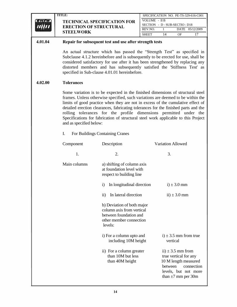
TITLE:
TECHNICAL SPECIFICATION FOR
ERECTION OF STRUCTURAL
STEELWORK
SPECIFICATION NO. PE-TS-329-616-C001
VOLUME - II B
SECTION - D - SUB-SECTIO : D18
REV.NO. 1 DATE 05/12/2009
SHEET 14 OF 17
4.01.04 Repair for subsequent test and use after strength tests
An actual structure which has passed the “Strength Test” as specified in
Subclause 4.1.2 hereinbefore and is subsequently to be erected for use, shall be
considered satisfactory for use after it has been strengthened by replacing any
distorted members and has subsequently satisfied the 'Stiffness Test' as
specified in Sub-clause 4.01.01 hereinbefore.
4.02.00 Tolerances
Some variation is to be expected in the finished dimensions of structural steel
frames. Unless otherwise specified, such variations are deemed to be within the limits of good practice when they are not in excess of the cumulative effect of
detailed erection clearances, fabricating tolerances for the finished parts and the rolling tolerances for the profile dimensions permitted under the
Specifications for fabrication of structural steel work applicable to this Project
and as specified below:
I. For Buildings Containing Cranes
Component Description Variation Allowed
1. 2. 3.
Main columns a) shifting of column axis at foundation level with
respect to building line
i) In longitudinal direction i) ± 3.0 mm
ii) In lateral direction ii) ± 3.0 mm b) Deviation of both major column axis from vertical
between foundation and other member connection levels:
i) For a column upto and i) ± 3.5 mm from true
including 10M height vertical
ii) For a column greater ii) ± 3.5 mm from
than 10M but less true vertical for any than 40M height 10 M length measured
between connection levels, but not more than ±7 mm per 30m
14
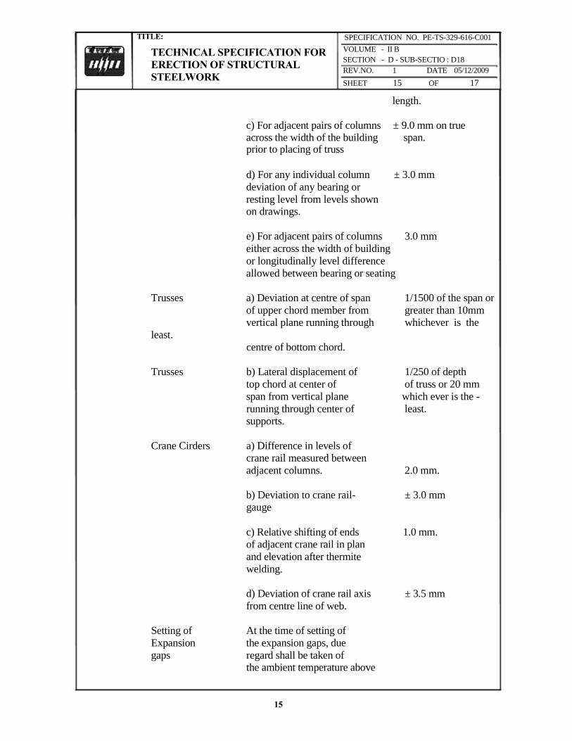
TITLE:
TECHNICAL SPECIFICATION FOR
ERECTION OF STRUCTURAL
STEELWORK
SPECIFICATION NO. PE-TS-329-616-C001
VOLUME - II B
SECTION - D - SUB-SECTIO : D18
REV.NO. 1 DATE 05/12/2009
SHEET 15 OF 17
length.
c) For adjacent pairs of columns ± 9.0 mm on true across the width of the building span. prior to placing of truss
d) For any individual column ± 3.0 mm
deviation of any bearing or
resting level from levels shown on drawings.
e) For adjacent pairs of columns 3.0 mm
either across the width of building
or longitudinally level difference
allowed between bearing or seating
Trusses a) Deviation at centre of span 1/1500 of the span or
of upper chord member from greater than 10mm vertical plane running through whichever is the
least.
centre of bottom chord.
Trusses b) Lateral displacement of 1/250 of depth
top chord at center of of truss or 20 mm
span from vertical plane which ever is the -
running through center of least. supports.
Crane Cirders a) Difference in levels of crane rail measured between
adjacent columns. 2.0 mm.
b) Deviation to crane rail- ± 3.0 mm gauge
c) Relative shifting of ends 1.0 mm. of adjacent crane rail in plan
and elevation after thermite
welding.
d) Deviation of crane rail axis ± 3.5 mm
from centre line of web.
Setting of At the time of setting of
Expansion the expansion gaps, due
gaps regard shall be taken of the ambient temperature above
15

TITLE:
TECHNICAL SPECIFICATION FOR
ERECTION OF STRUCTURAL
STEELWORK
SPECIFICATION NO. PE-TS-329-616-C001
VOLUME - II B
SECTION - D - SUB-SECTIO : D18
REV.NO. 1 DATE 05/12/2009
SHEET 16 OF 17
or below 30°C. The coefficient of expansion or contraction shall be taken as 0.000012 per °C per unit length.
iv) For Building without Cranes
The maximum tolerances for line and level of the steel work shall be ±3.0 mm on any part of the structure. The structure shall not be Out of Plumb more than 3.5 mm on each lox section of height and not more than 7.0 mm per 30 m section.
These tolerances shall apply to all parts of the structure unless the drawings issued for erection purposes state otherwise.
4.03.00 Acceptance
Structures and members have passed the tests and conform to all requirements
specified in the foregoing Sub-clause 4.01.00, 4.01.01, 4.01.02, 4.01.03 and
4.01.04 and other applicable provisions of this specification and are within the limits of tolerances specified in Sub-clause 4.02.00 and/or otherwise approved by the Engineer shall be treated as approved and accepted for the purpose of
fulfillment of the provisions of this contract.
5.00.00 INFORMATION TO BE SUBMITTED
5.01.00 Before Tender
5.01.01 Tentative Programme
The Tenderer shall submit a tentative programme based on the information available in the Tender Document and visit to site indicating the structurewise erection schedule proposed to be maintained by the Contractor to complete the job in time in accordance with the Contract.
5.01.02 Constructional Plant and Equipment, Tools, Temporary works & manpower A
detailed list Of all constructional plant and equipment like cranes, derricks, winches, welding sets, erection tools etc. along with their make, model,
present condition and location available with the Tenderer which he will be able to employ on the job to maintain the progress of work in accordance with
the Contract shall be submitted along with the Tender. The total number of
each category of experienced personnel like fitters, welders, riggers etc. that he will be able to employ on the job shall also be indicated.
5.01.03 Erection Yard A site plan showing the layout and location of the erection yard proposed to be
16

TITLE:
TECHNICAL SPECIFICATION FOR
ERECTION OF STRUCTURAL
STEELWORK
SPECIFICATION NO. PE-TS-329-616-C001
VOLUME - II B
SECTION - D - SUB-SECTIO : D18
REV.NO. 1 DATE 05/12/2009
SHEET 17 OF 17
established by the tenderer shall also be attached with the tender indicating the storage space for fabricated steel materials, site-fabrication and repair shop, covered stores, offices, locations of erection equipments and other facilities. The Engineer shall have the right to modify the arrangement and location of the proposed yard to suit site conditions and the Contractor shall comply with the same without any claim whatsoever.
5.02.00 After award of the Contract
After award of the contract, the Contractor shall submit the following:
5.02.01 Detailed Programme
The Contractor shall submit a detailed erection programme within a month of the award of the Contract for completion of the work in time in accordance
with the Contract. This will show the target programme, with details of
erection proposed to be carried out in each fortnight, details of major
equipment required, and an assessment of required strength of various
categories of workers in a proforma approved by the Engineer.
5.02.02 Fortnightly Progress Report
The Contractor shall submit fortnightly progress reports in triplicate to the
Engineer showing along with necessary photographs, 125 mm x 90 mm size, and all details of actual achievements against the target programme specified in
Sub-clause 5.02.01 above. Any shortfall in the achievement in a particular fortnight must be made up within the next fortnight. Along with this report,
the Contractor shall also furnish details of fabricated materials in hand at site
and the strength of his workers.
17