Embed Size (px)
Citation preview
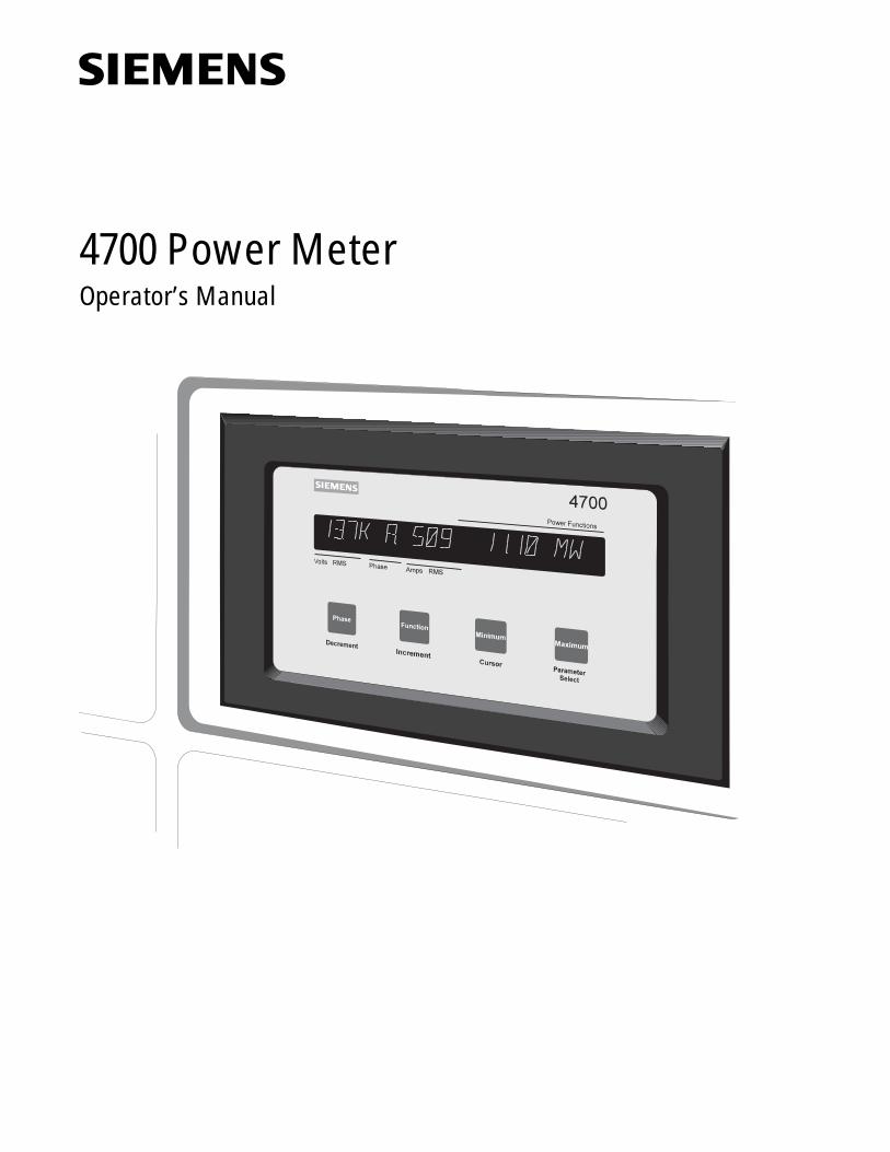
4700 Power MeterOperator’s Manual
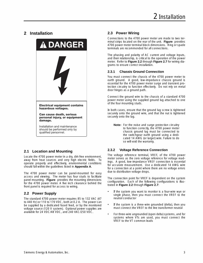
DANGERHazardous voltages and high-speed moving parts in electrical devices communicating with the Power Meter.
Can cause death, serious injury or property damage.
See safety instruction contained herein. Restrict use to qualified personnel.
The use of unauthorized parts in the repair of the equipment or tampering by unqualified personnel will result in dangerous conditions that can cause death, serious injury or property damage.
IMPORTANT
The information contained herein is general in nature and not intended for specific application purposes. It does not relieve the user of responsibility to use sound practices in appli-cation, installation, operation, and maintenance of the equipment purchased. Siemens reserves the right to make changes at any time without notice or obligations. Should a conflict arise between the general information contained in this publication and the contents of drawings or supple-mentary material or both, the latter shall take precedence.
QUALIFIED PERSONNEL
For the purposes of this manual and product labels, "qualified personnel" is one who is familiar with the installation, construction, or operation of the equipment and the hazards involved. In addition, s/he has the following qualifications:
(a) is trained and authorized to energize, de-energize, clear, ground, and tag circuits and equipment in accordance with established safety practices.
(b) is trained in the proper care and use of protective gear equipment such as rubber gloves, hard hat, safety glasses or face shields, flash clothing, etc., in accordance with established safety procedures
(c) is trained in rendering first aid.
SUMMARYThese instructions do not purport to cover all details or variations in equipment, nor to provide for every possible contingency to be met in connection with installation, operation, or maintenance. Should further infor-mation be desired or should particular problems arise which are not covered sufficiently for the purchaser’s purposes, the matter should be referred to the local Siemens Energy & Automation, Inc. sales office.THE CONTENTS OF THIS INSTRUCTION MANUAL SHALL NOT BECOME PART OF OR MODIFY ANY PRIOR OR EXISTING AGREEMENT, COMMITMENT OR RELATIONSHIP. THE SALES CONTRACT CONTAINS ALL OBLIGA-TIONS OF SIEMENS ENERGY & AUTOMATION, INC. THE WARRANTY CONTAINED IN THE CONTRACT BETWEEN THE PARTIES IS THE SOLE WARRANTY OF SIEMENS ENERGY & AUTOMATION, INC.ACCESS, ISGS, Isolated Multi-Drop, S7-I/O, SBwin, SAMMS-LV, SAAMS-MV,SEAbus,SIEServe, Static Trip III, Wisdom, and WinPM are trademark, Sensitrip and Sentron are registered trademarks of Siemens Energy & Automation, Inc. SIEMENS is a registered trademark of Siemens AG. Windows is a trademark of Microsoft Corporation. All other product names mentioned herein are used for identification purposes only and may be the trademarks or registered trademarks of their respective companies.
Table of Contents
Siemens Energy & Automation, Inc. i
Appendixes1 Introduction ...............................................1
1.1 About the 4700 Power Meter ...............................1
1.2 Performance Features ..........................................1
1.3 Displays and Measurements.................................1
1.4 Other Functions....................................................2
1.4.1 Logging Capability......................................21.4.2 Control Relays ............................................21.4.3 Status Inputs ..............................................21.4.4 Auxiliary Voltage Input ................................21.4.5 Auxiliary Current Output .............................2
1.5 Communications and ACCESS Compatibility .......2
1.6 System Applications.............................................2
2 Installation .................................................3
2.1 Location and Mounting.........................................3
2.2 Power Supply.......................................................3
2.3 Power Wiring........................................................3
2.3.1 Chassis Ground Connection ......................32.3.2 Voltage Reference Connection...................32.3.3 Fourth Current Input Connections..............52.3.4 Waveform Capture Connections ................5
2.4 Selecting Voltage and Current Transformers .........5
2.4.1 Selecting VTs ..............................................52.4.2 Selecting CTs..............................................5
2.5 Connecting to 3-Phase, Wye (Star) Systems ........6
2.6 Connecting to Three-Phase, Delta Systems .........9
2.7 Connecting to Single Phase, Three-Wire Systems ..11
3 Communications Wiring.........................13
3.1 Configuring the Communications Card ...............13
3.2 Terminal and LED Indicator Functions................. 14
3.3 RS-232 Connections.......................................... 14
3.4 RS-485 Connections.......................................... 15
4 Optional Wiring........................................17
4.1 Status Inputs...................................................... 17
4.1.1 Dry (Volts Free) Contact Sensing.............. 174.1.2 Voltage Sensing........................................ 18
4.2 Control Relay Connections ................................. 18
4.2.1 Relay Application Precautions.................. 18
4.3 Auxiliary Voltage Input ........................................ 20
4.4 Auxiliary Current Output......................................20
5 Operator Interface.................................. 21
5.1 Start Up .............................................................21
5.2 Front Panel Operation.........................................21
5.2.1 ........................... Standard Phase Display215.2.2 Full Width Display .....................................215.2.3 Three-Phase Displays...............................215.2.4 Phase Button ............................................215.2.5 Function Button ........................................225.2.6 Minimum and Maximum Buttons .............22
5.3 Power Reading Polarities....................................23
6 Programming .......................................... 25
6.1 Programming Mode............................................25
6.1.1 Programming Button Functions ...............256.1.2 Entering the Password .............................256.1.3 Changing the Password ...........................256.1.4 Skipping Over the Setpoint Parameters ...26
6.2 Basic Settings ....................................................26
6.2.1 Volt Scale..................................................266.2.2 Amps Scale...............................................266.2.3 Volts Mode................................................26
6.3 Additional Settings..............................................26
6.3.1 Auxiliary Voltage Input Operation .............266.3.2 Auxiliary Current Output Operation ..........266.3.3 Display Format..........................................29
6.4 Control Relay Operation .....................................29
6.4.1 Control Relay Modes ................................296.4.2 Access to Relay Parameters ....................296.4.3 Setpoint Relay Operation .........................296.4.4 kVARH and kWH Pulse Operation............296.4.5 Manual Forced Relay Operations .............296.4.6 Relay Event Logging.................................306.4.7 Manual Relay Command Special Cases ..306.4.8 Relay Operation After Power Outages .....30
6.5 Bi-Directional Energy ..........................................30
6.6 Status Input Operation .......................................30
6.7 Fourth Current Input Operation...........................30
6.8 Waveform Capture .............................................30
6.9 Operating Parameter Descriptions ......................31
7 Using Setpoints.......................................35
7.1 Applications ....................................................... 35
7.2 Over Setpoint ..................................................... 35
7.3 Under Setpoint ................................................... 36
Table of Contents
ii Siemens Energy & Automation, Inc.
7.4 Programming Setpoints ......................................36
8 Demand Calculation ...............................39
8.1 Demand Measurement Methods ........................39
8.2 Internally Timed Demand Measurement..............39
8.3 Demand Synchronization....................................39
9 Communications.....................................41
9.1 General ..............................................................41
9.2 RS-232 Communications ...................................41
9.3 RS-485 Communications ...................................41
9.4 Setting the Unit ID and Baud Rate ......................41
9.5 Siemens WinPM Software ..................................42
9.6 Third-Party System Compatibility ........................42
10 Maintenance............................................43
10.1Battery Replacement ..........................................43
10.2Calibration ..........................................................43
10.3Field Service Considerations...............................43
11 Troubleshooting ......................................44
A Technical Specifications .......................45
B Dimensions.............................................47
C Setpoint Parameter Form .....................48
D Firmware Versions .................................49
E Ordering Information.............................50
Warranty
Index© 1996 Siemens Energy & Automation, Inc.
ACCESS, Isolated Multi-Drop, SEAbus, SIEServe, Power Monitor, and WinPMare trademarks of Siemens Energy & Automation, Inc. Windows is a trademark and Microsoft is a registered trademark of MicrosoftCorporation. Other product names are trademarks of their respective holders.
1 Introduction
Siemens Energy & Automation, Inc. 1
1 Introduction
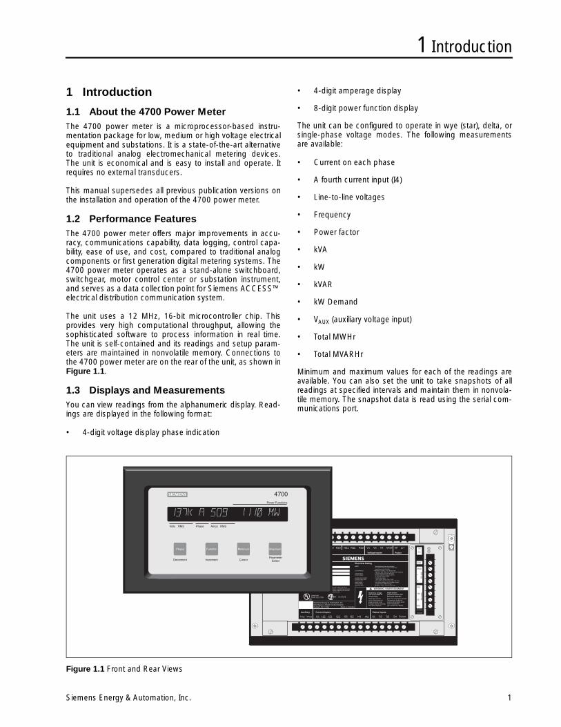
1.1 About the 4700 Power MeterThe 4700 power meter is a microprocessor-based instru-mentation package for low, medium or high voltage electricalequipment and substations. It is a state-of-the-art alternativeto traditional analog electromechanical metering devices.The unit is economical and is easy to install and operate. Itrequires no external transducers.
This manual supersedes all previous publication versions onthe installation and operation of the 4700 power meter.
1.2 Performance FeaturesThe 4700 power meter offers major improvements in accu-racy, communications capability, data logging, control capa-bility, ease of use, and cost, compared to traditional analogcomponents or first generation digital metering systems. The4700 power meter operates as a stand-alone switchboard,switchgear, motor control center or substation instrument,and serves as a data collection point for Siemens ACCESS™electrical distribution communication system.
The unit uses a 12 MHz, 16-bit microcontroller chip. Thisprovides very high computational throughput, allowing thesophisticated software to process information in real time.The unit is self-contained and its readings and setup param-eters are maintained in nonvolatile memory. Connections tothe 4700 power meter are on the rear of the unit, as shown inFigure 1.1.
1.3 Displays and MeasurementsYou can view readings from the alphanumeric display. Read-ings are displayed in the following format:
• 4-digit voltage display phase indication
• 4-digit amperage display
• 8-digit power function display
The unit can be configured to operate in wye (star), delta, orsingle-phase voltage modes. The following measurementsare available:
• Current on each phase
• A fourth current input (I4)
• Line-to-line voltages
• Frequency
• Power factor
• kVA
• kW
• kVAR
• kW Demand
• VAUX (auxiliary voltage input)
• Total MWHr
• Total MVARHr
Minimum and maximum values for each of the readings areavailable. You can also set the unit to take snapshots of allreadings at specified intervals and maintain them in nonvola-tile memory. The snapshot data is read using the serial com-munications port.
Figure 1.1 Front and Rear Views
TXD
SG
RTS
SHLD
+
GND
RXD
RS
-23
2C
RS
-48
5
-
SIEMENS
ISOCOM
RXD
TXDR11 R12 R13 R21 R22 R23 R31 R32 R33 V1 V2 V3 VREF N/- L/+
IOut VAux I11 I12 I21 I22 I31 I32 I41 I42 S1 S2 S3 S4 SCOM
Control Relays Voltage Inputs Power
WARNING / AVERTISSEMENT
Hazardous voltage.Can cause death orsevere injury.
More than one livecircuit. Disconnect allpower sources to de-energize before servicing.See wiring diagram.
Haute tensionpouvant entrainer desblessures mortelles.
Plus d’un circuit sous-tension.Déconnecter toutes lessources de tensions avanttoute manipulation.Voir schéma de cablage.
Auxiliary Current Inputs Status Inputs
Siemens Energy & Automation, Inc.Switchgear & Motor Control DivisionRaleigh, NC • USA Made in Canada
R
RListed Ind.Contr. Eq. 1T98 LR 57329
This equipment complies with the requirements in part 15 of FCC rules for aClass A computing device. Operation of this equipment in a residential area maycause inacceptable interference to radio and TV reception requiring the operatorto take whatever steps are necessary to correct the interference.
Serial Number:Software Version:
4700 Power Meter Electrical RatingNOTE: Specifications below are standard.
For options refer to model number andinstruction book SG-6068.
Control Relays: Resistive: 10 Amp, 277 V AC/30 VDCInductive: 240 VAC, 3400 VA Make, 360 VA Break
Voltage Inputs: Line to Neutral 120 VAC NominalPower Supply: 85-264 VACC/0.2 Amp, 47-440 Hz
or 110-300 VDC/0.2 AmpAuxiliary IOut Output: 0 to 20 mA OutputAuxiliary VAux Input: 1 Volt AC/DC Input, Class 2 onlyCurrent Inputs: 5 Amp AC only, 25% Overrange, 30V Max.Status Inputs: Dry contact sensing. Do not apply voltage.Terminal Strip: 12 Lbs-inch (1.35Nm) TorqueMaximum Wire: 12 AWG, 4 mm², 75°C Cu wire only
1 Introduction
2 Siemens Energy & Automation, Inc.
1.4 Other Functions
1.4.1 Logging Capability
The 4700 power meter can record up to three data logs.
• EVENT Log. This log records events such as power up,parameter changes, alarm conditions, relay changes,and status input changes. The 50 most recent eventsare retrievable from this log using the communicationsport.
• SNAPSHOT Log. This log contains voltage, current, andall power values recorded at user-defined time intervals.The 100 most recent snapshots are retrievable from thislog using the communications port.
• MIN/MAX Log. This log records the extreme values forvoltages, currents, power, and other measured parame-ters. Min/Max data is read using the integral display orthe communications port.
All log contents (events, snapshots, and min/max values) aretime-stamped to the second.
1.4.2 Control Relays
The 4700 power meter has three control relay options.
• Alarm relays and setpoint relays. These can operate as afunction of any measured parameter for demand, powerfactor, or load control.
• Remote control relays, operated by command via thecommunications port.
• kVARHr, kWHr pulse outputs.
1.4.3 Status Inputs
The 4700 power meter has four status input options avail-able, which can each sense the state of an external contact,active or inactive. The status of these inputs is viewed andlogged by a Power Monitor™ display and monitoring unit, orby another computer through the communications port.
1.4.4 Auxiliary Voltage Input
All 4700 power meter models have an auxiliary voltage inputthat allows monitoring and display of an additional externalvoltage (1.25 VAC max).
1.4.5 Auxiliary Current Output
You can program an optional analog current output for 0 to20 mA or 4 to 20 mA, in proportion to any measured param-eter.
1.5 Communications and ACCESS Compatibility
The 4700 power meter is equipped with an optically isolatedcommunications port for displaying data on remote supervi-sory devices. These devices and programs allow the meterto operate in the ACCESS electrical distribution communica-tion system. Examples of supervisory devices include thePower Monitor display and monitoring unit, a standard per-sonal computer running the Power Monitor PC communica-tions and supervisory software, and Siemens Microsoft®Windows™-based SIEServe™ or WinPM™ communicationssoftware.
1.6 System ApplicationsThe unique features of the 4700 power meter, including mea-surement, storage, setpoint (load shedding) and displaycharacteristics, make it suitable for use in:
• Utility Installations
• Industrial Buildings
• Office Buildings
• Commercial Buildings
• Hospitals
• Telephone Exchanges
• Factories
• Pulp Mills
• Saw Mills
• Shopping Centers
• Large Stores
• Hotels
• Substation Metering
• Co-Generation Systems
• Chemical Process Plants
• Multi-User Sites (where allocation of electrical cost isdesirable)
• Any other installation that uses significant amounts ofelectrical energy
• Any other location where remote monitoring and controlis needed
2 Installation
Siemens Energy & Automation, Inc. 3
2 Installation
2.1 Location and MountingLocate the 4700 power meter in a dry, dirt-free environment,away from heat sources and very high electric fields. Tooperate properly and effectively, environmental conditionsshould fall within the guidelines listed in Appendix A.
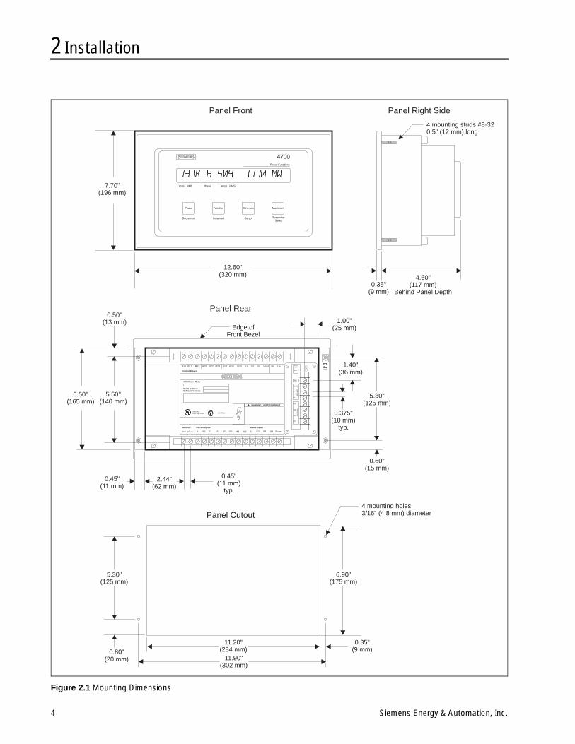
The 4700 power meter can be panel-mounted for easyaccess and viewing. The meter has four studs to facilitatepanel mounting. Figure provides the mounting dimensionsfor the 4700 power meter. A five inch clearance behind thefront panel is required for access to wiring.
2.2 Power SupplyThe standard 4700 power meter requires 85 to 132 VAC (47to 440 Hz) or 110 to 170 VDC, both at 0.2 A. The power canbe supplied by a dedicated fused feed, or by the monitoredvoltage source (120 V system). Optional power supplies areavailable for 24 VDC/48 VDC, and 240 VAC/250 VDC.
2.3 Power WiringConnections to the 4700 power meter are made to two ter-minal strips located on the rear of the unit. Figure provides4700 power meter terminal block dimensions. Ring or spadeterminals are recommended for all connections.
The phasing and polarity of AC current and voltage inputs,and their relationship, is critical to the operation of the powermeter. Refer to Figure 2.2 through Figure 2.7 for wiring dia-grams to ensure correct installation.
2.3.1 Chassis Ground Connection
You must connect the chassis of the 4700 power meter toearth ground. A good, low-impedance chassis ground isessential for the 4700 power meter surge and transient pro-tection circuitry to function effectively. Do not rely on metaldoor hinges as a ground path.
Connect the ground wire to the chassis of a standard 4700power meter using the supplied ground lug attached to oneof the four mounting studs.
In both cases, ensure that the ground lug screw is tightenedsecurely onto the ground wire, and that the nut is tightenedsecurely onto the lug.
Note: For the noise and surge protection circuitryto function correctly, the 4700 power meterchassis ground lug must be connected tothe switchgear earth ground using a dedi-cated 14 AWG (or larger) wire. Failure to doso will void the warranty.
2.3.2 Voltage Reference Connection
The voltage reference terminal, VREF, of the 4700 powermeter serves as the zero voltage reference for voltage read-ings. A good, low-impedance VREF connection is essentialfor accurate measurement. Use a dedicated 14 AWG wirefor a connection at a point where there are no voltage errorsdue to distribution voltage drops.
The connection point for VREF is dependent on the systemconfiguration. Each of the following configurations is illus-trated in Figure 2.2 through Figure 2.7:
• If the system you want to monitor is a four-wire wye orsingle phase, then you must connect the VREF to theneutral conductor
• If the system is a three-wire grounded (delta), then youmust connect the VREF to the line transformer neutral
• For three-wire ungrounded (open delta) systems, and forsystems where VTs are used, you must connect theVREF to the VT common leads
2 Installation
4 Siemens Energy & Automation, Inc.
Figure 2.1 Mounting Dimensions
0.35"(9 mm)
4.60"(117 mm)
Behind Panel Depth
4 mounting studs #8-320.5" (12 mm) long
7.70"(196 mm)
12.60"(320 mm)
TXD
SG
RTS
SHLD
+
GND
RXD
RS
-23
2C
RS
-48
5
-
4720
SIEMENSISOCOM
RXD
TXDR11 R12 R13 R21 R22 R23 R31 R32 R33 V1 V2 V3 VREF N/- L/+
IOut VAux I11 I12 I21 I22 I31 I32 I41 I42 S1 S2 S3 S4 SCOM
Control Relays Voltage Inputs Power
WARNING / AVERTISSEMENT
Auxiliary Current Inputs Status Inputs
Listed Ind.Contr. Eq. 1T98 LR 57329
Serial Number:Software Version:
4700 Power Meter
0.50’’(13 mm)
6.50’’(165 mm)
5.50’’(140 mm)
Edge ofFront Bezel
0.45"(11 mm)
typ.
0.375"(10 mm)
typ.
2.44"(62 mm)
0.45"(11 mm)
1.00"(25 mm)
1.40"(36 mm)
5.30"(125 mm)
5.30"(125 mm)
6.90"(175 mm)
11.20"(284 mm)
0.35"(9 mm)0.80"
(20 mm) 11.90"(302 mm)
0.60"(15 mm)
Panel Front Panel Right Side
Panel Rear
Panel Cutout4 mounting holes3/16" (4.8 mm) diameter
2 Installation
Siemens Energy & Automation, Inc. 5
2.3.3 Fourth Current Input Connections
The 4700 power meter is equipped with a fourth currentinput, labeled I4. This input is typically used to measure thecurrent flow in the neutral or ground conductor. The use ofthis input is optional. If not used, connect the I41 and I42terminals to earth ground.
The secondary rating of the CT connected to the I4 inputmust match the three phase current inputs. This ratingdepends on the presently installed input option in the 4700power meter.
The primary rating for the CT connected to the I4 input candiffer from the three phase inputs, since the I4 input scaling isindependently programmable.
2.3.4 Waveform Capture Connections
The 4700 power meter waveform capture feature allows dig-ital sampling of signals at each of its voltage (V1, V2, V3,Vaux) inputs and current (I1, I2, I3, I4) inputs. The 4700power meter uses the V1 input as the triggering reference forwaveform capture, and to maintain phase relationshipsbetween all sampled signals. You must connect the V1 inputfor waveform capture to work. No other special wiring con-siderations are necessary. Waveform capture is accessibleonly via communications. See section 6.8 in Chapter 6 formore information about how to use waveform capture.
2.4 Selecting Voltage and Current Transformers
Selection of correct current transformers (CTs) and voltagetransformers (VTs) is critical to proper monitoring. This sec-tion describes how to choose transformers.
2.4.1 Selecting VTs
The requirement and selection of VTs depends on three crite-ria: the system monitored, the voltage levels monitored, andthe model of the 4700 power meter.
For connecting directly to 120/208 VAC systems, the 120VAC (full scale) input model is used. It is also used for sys-tems with VTs having a 120 VAC secondary. For connectingdirectly to a 277/480 VAC system, the 277 VAC (full scale)input model is used. For connecting a 347/600 VAC system,the 347 VAC (full scale) input model is used. If system volt-ages are over 347/600 VAC, then VTs are required.
VTs are used to scale down the system voltage to 120 VACfull scale. The system voltage is line-to-neutral (L-N) for wyesystems or line-to-line (L-L) for delta systems. 120 VAC is thenominal scale input of the 4700 power meter.
The VTs are selected as follows:
a. Wye (star): VT primary rating is the system L-N voltageor nearest higher standard size. VT secondary rating is120 V.
b. Delta: VT primary rating is the system L-L voltage. VTsecondary rating is 120 V.
VT quality directly affects system accuracy. Therefore, forvalid Volts, kW and PF readings, the VTs must provide goodlinearity and maintain the proper phase relationship betweenvoltage and current. Instrument Accuracy Class 1 or betteris recommended.
2.4.2 Selecting CTs
The 4700 power meter uses CTs to sense the current in eachphase of the power feed. The selection of the CTs is impor-tant because it directly affects accuracy.
The CT secondary rating is always 5 A with a burden capac-ity greater than 3 VA (burden is the amount of load fed by theCT, measured in Volt-Amps).
Normally, the CT primary rating is selected equal to the Amprating of the power feed protection device. However, if theanticipated peak load is much less than the rated systemcapacity, then improved accuracy and resolution is obtainedby selecting a lower rated CT. In this case, choose the CTsize equal to the maximum anticipated peak current plus25%, rounded up to the nearest standard CT size available.
Other factors affect CT accuracy. Because long cable runscontribute to inaccuracy, try to minimize the length of the CTcable. Also, the CT burden rating must exceed the com-bined burden of the 4700 power meter plus cabling and anyother connected devices.
VT and CT ConsiderationsProtect all phase voltage leads with breakers or fuses at theirsource. In cases where VTs are required and the power rat-ing of the VTs is over 25 W, fuse the secondaries.
Connect CTs to the device via a shorting block or test blockto facilitate safe connection and disconnection.
Refer questions regarding proper working procedures toqualified personnel.
2 Installation
6 Siemens Energy & Automation, Inc.
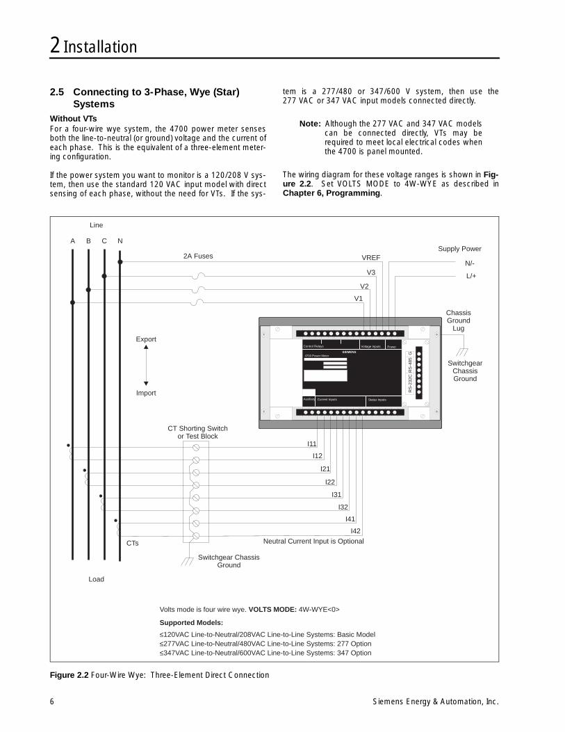
2.5 Connecting to 3-Phase, Wye (Star) Systems
Without VTsFor a four-wire wye system, the 4700 power meter sensesboth the line-to-neutral (or ground) voltage and the current ofeach phase. This is the equivalent of a three-element meter-ing configuration.
If the power system you want to monitor is a 120/208 V sys-tem, then use the standard 120 VAC input model with directsensing of each phase, without the need for VTs. If the sys-
tem is a 277/480 or 347/600 V system, then use the277 VAC or 347 VAC input models connected directly.
Note: Although the 277 VAC and 347 VAC modelscan be connected directly, VTs may berequired to meet local electrical codes whenthe 4700 is panel mounted.
The wiring diagram for these voltage ranges is shown in Fig-ure 2.2. Set VOLTS MODE to 4W-WYE as described inChapter 6, Programming.
Figure 2.2 Four-Wire Wye: Three-Element Direct Connection
GR
S-4
85R
S-2
32C
Control Relays Voltage Inputs Power
Auxiliary Current Inputs Status Inputs
4700 Power MeterSIEMENS
I11
I12
I21
I22
I31
I32
I41
I42
Switchgear ChassisGround
SwitchgearChassisGround
CT Shorting Switchor Test Block
Neutral Current Input is Optional
ChassisGround
Lug
Line
A B C N
2A Fuses
Export
Import
Load
CTs
N/-
L/+
VREF
V3
V2
V1
Supply Power
Supported Models:
≤120VAC Line-to-Neutral/208VAC Line-to-Line Systems: Basic Model≤277VAC Line-to-Neutral/480VAC Line-to-Line Systems: 277 Option≤347VAC Line-to-Neutral/600VAC Line-to-Line Systems: 347 Option
Volts mode is four wire wye. VOLTS MODE: 4W-WYE<0>
2 Installation
Siemens Energy & Automation, Inc. 7
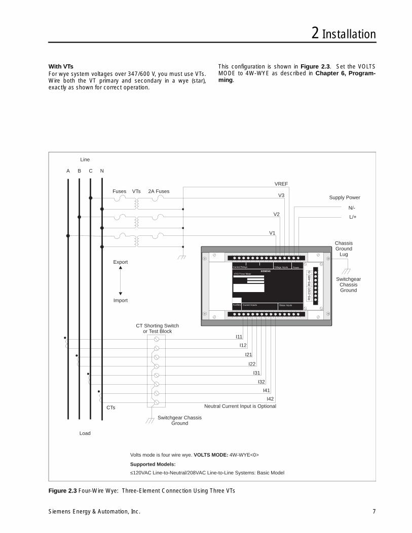
With VTsFor wye system voltages over 347/600 V, you must use VTs.Wire both the VT primary and secondary in a wye (star),exactly as shown for correct operation.
This configuration is shown in Figure 2.3. Set the VOLTSMODE to 4W-WYE as described in Chapter 6, Program-ming.
Figure 2.3 Four-Wire Wye: Three-Element Connection Using Three VTs
I11
I12
I21
I22
I31
I32
I41
I42
Switchgear ChassisGround
SwitchgearChassisGround
CT Shorting Switchor Test Block
Neutral Current Input is Optional
ChassisGround
Lug
Line
A B C N
2A FusesFuses VTs
Export
Import
Load
CTs
N/-
L/+
VREF
V3
V2
V1
Supply Power
Supported Models:
≤120VAC Line-to-Neutral/208VAC Line-to-Line Systems: Basic Model
Volts mode is four wire wye. VOLTS MODE: 4W-WYE<0>
2 Installation
8 Siemens Energy & Automation, Inc.
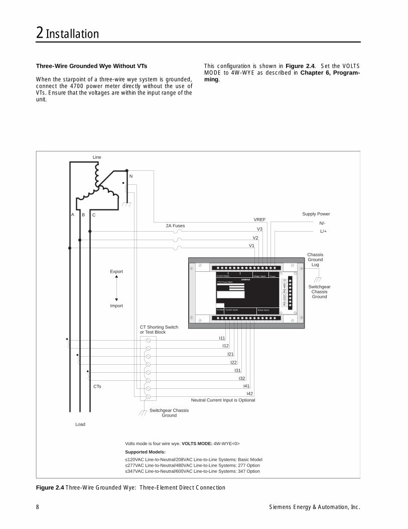
Three-Wire Grounded Wye Without VTs
When the starpoint of a three-wire wye system is grounded,connect the 4700 power meter directly without the use ofVTs. Ensure that the voltages are within the input range of theunit.
This configuration is shown in Figure 2.4. Set the VOLTSMODE to 4W-WYE as described in Chapter 6, Program-ming.
Figure 2.4 Three-Wire Grounded Wye: Three-Element Direct Connection
I11
I12
I21
I22
I31
I32
I41
I42
Switchgear ChassisGround
SwitchgearChassisGround
CT Shorting Switchor Test Block
Neutral Current Input is Optional
ChassisGround
Lug
Line
A B C
N
2A Fuses
Export
Import
Load
CTs
N/-
L/+
VREF
V3
V2
V1
Supply Power
Supported Models:
≤120VAC Line-to-Neutral/208VAC Line-to-Line Systems: Basic Model≤277VAC Line-to-Neutral/480VAC Line-to-Line Systems: 277 Option≤347VAC Line-to-Neutral/600VAC Line-to-Line Systems: 347 Option
Volts mode is four wire wye. VOLTS MODE: 4W-WYE<0>
2 Installation
Siemens Energy & Automation, Inc. 9
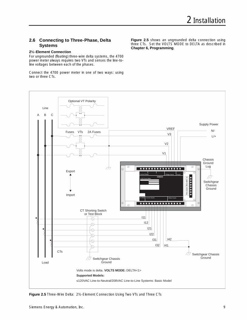
2.6 Connecting to Three-Phase, Delta Systems
2½-Element ConnectionFor ungrounded (floating) three-wire delta systems, the 4700power meter always requires two VTs and senses the line-to-line voltages between each of the phases.
Connect the 4700 power meter in one of two ways: usingtwo or three CTs.
Figure 2.5 shows an ungrounded delta connection usingthree CTs. Set the VOLTS MODE to DELTA as described inChapter 6, Programming.
Figure 2.5 Three-Wire Delta: 2½-Element Connection Using Two VTs and Three CTs
I11
I12
I21
I22
I31
I41I32
I42
Switchgear ChassisGround
Switchgear ChassisGround
SwitchgearChassisGround
CT Shorting Switchor Test Block
ChassisGround
Lug
Line
A B C
2A FusesFuses VTs
Optional VT Polarity
Export
Import
Load
CTs
N/-
L/+
VREF
V3
V2
V1
Supply Power
Supported Models:
≤120VAC Line-to-Neutral/208VAC Line-to-Line Systems: Basic Model
Volts mode is delta. VOLTS MODE: DELTA<1>
2 Installation
10 Siemens Energy & Automation, Inc.
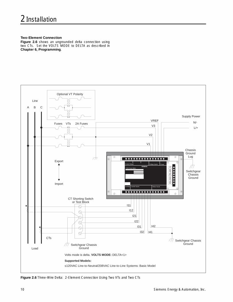
Two-Element ConnectionFigure 2.6 shows an ungrounded delta connection usingtwo CTs. Set the VOLTS MODE to DELTA as described inChapter 6, Programming.
Figure 2.6 Three-Wire Delta: 2-Element Connection Using Two VTs and Two CTs
I11
I12
I21
I22
I31
I41I32
I42
Switchgear ChassisGround
Switchgear ChassisGround
SwitchgearChassisGround
CT Shorting Switchor Test Block
ChassisGround
Lug
Line
A B C
2A FusesFuses VTs
Optional VT Polarity
Export
Import
Load
CTs
N/-
L/+
VREF
V3
V2
V1
Supply Power
Supported Models:
≤120VAC Line-to-Neutral/208VAC Line-to-Line Systems: Basic Model
Volts mode is delta. VOLTS MODE: DELTA<1>
2 Installation
Siemens Energy & Automation, Inc. 11
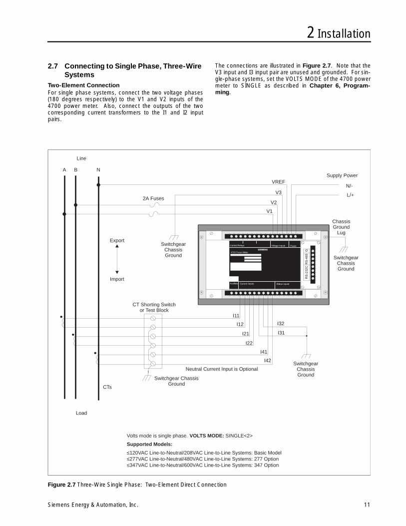
2.7 Connecting to Single Phase, Three-Wire Systems
Two-Element ConnectionFor single phase systems, connect the two voltage phases(180 degrees respectively) to the V1 and V2 inputs of the4700 power meter. Also, connect the outputs of the twocorresponding current transformers to the I1 and I2 inputpairs.
The connections are illustrated in Figure 2.7. Note that theV3 input and I3 input pair are unused and grounded. For sin-gle-phase systems, set the VOLTS MODE of the 4700 powermeter to SINGLE as described in Chapter 6, Program-ming.
Figure 2.7 Three-Wire Single Phase: Two-Element Direct Connection
I11
I12
I21
I22
I31
I32
I41
I42
Switchgear ChassisGround
SwitchgearChassisGround
SwitchgearChassisGround
SwitchgearChassisGround
CT Shorting Switchor Test Block
Neutral Current Input is Optional
ChassisGround
Lug
Line
A B N
2A Fuses
Export
Import
Load
CTs
N/-
L/+
VREF
V3
V2
V1
Supply Power
Supported Models:
Volts mode is single phase. VOLTS MODE: SINGLE<2>
≤120VAC Line-to-Neutral/208VAC Line-to-Line Systems: Basic Model≤277VAC Line-to-Neutral/480VAC Line-to-Line Systems: 277 Option≤347VAC Line-to-Neutral/600VAC Line-to-Line Systems: 347 Option

2 Installation
12 Siemens Energy & Automation, Inc.
3 Communications Wiring
Siemens Energy & Automation, Inc. 13
3 Communications WiringThe communications option of the 4700 power meterincludes a communications card. The card is field config-urable to allow the 4700 power meter to communicate usingeither the EIA/TIA-232 (RS-232) or EIA/TIA-485 (RS-485)standard. Optical coupling provides full isolation between theRS-232 or RS-485 communications lines and the meteringequipment. Internal circuitry protects against common modevoltages or incorrect connection of the optional communica-tions card. All inputs pass the ANSI/IEEE C37-90A-1989tests for withstanding surge and fast transient.
The following sections describe configuration instructionsand wiring requirements for direct connection to a mastercomputer station.
The communications card is shipped with a label affixed tothe mounting plate indicating the communications mode(RS-485 or RS-232) set at the factory. If the mode is incor-rect for your application, refer to the following section forchanging the configuration.
3.1 Configuring the Communications CardThis section describes how to change the communicationsmode of the 4700 communications card. You can selectRS-232 or RS-485 lines by switching a jumper block on thecard. The presently selected communications mode may beviewed from the power meter front panel, or by removing thecard and examining the position of the jumper block. (SeeChapter 5, Operator Interface for instructions on how touse the power meter front panel to display the communica-tions mode.)
To remove the card for configuration:
1. Turn off the power to the 4700 power meter.
2. Remove the four machine screws holding the rectangu-lar communications card mounting plate to the 4700power meter case back cover.
3. Carefully pull the plate away from the main chassis toremove the card.
To configure the card:
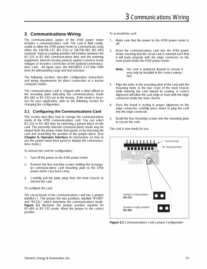
The circuit board of the communications card has a jumperlabelled J1. This jumper has two positions, labelled “RS485”and “RS232,” which determine the communications mode.Figure 3.1 illustrates the jumper position required forRS-485 or RS-232 mode. Move the jumper to the correctposition.
To re-install the card:
1. Make sure that the power to the 4700 power meter isoff.
2. Insert the communications card into the 4700 powermeter, ensuring that the circuit card is oriented such thatit will mate properly with the edge connector on themain board inside the 4700 power meter.
Note: The card is polarized (keyed) to ensure itmay only be installed in the correct orienta-tion.
3. Align the holes in the mounting plate of the card with themounting holes in the rear cover of the main chassiswhile lowering the card toward its seating. A correctalignment will allow the card edge to mate with the edgeconnector inside the main chassis.
4. Once the board is resting in proper alignment on theedge connector, carefully press down to plug the cardinto the edge connector.
5. Install the four mounting screws into the mounting plateto secure the card.
The card is now ready for use.
Figure 3.1 Communications Card Jumper Configuration
Terminal Strip
Mounting Plate
Jumper in left positionRS-232
Jumper in right positionRS-485
3 Communications Wiring
14 Siemens Energy & Automation, Inc.
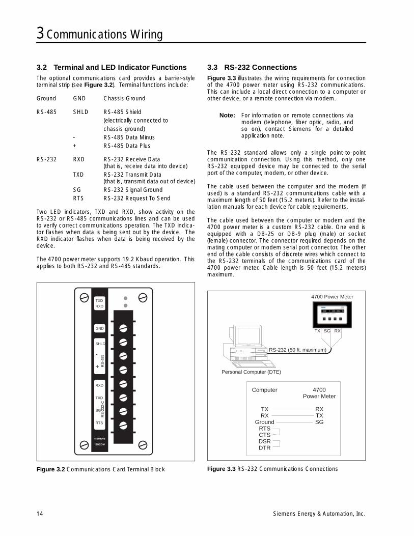
3.2 Terminal and LED Indicator FunctionsThe optional communications card provides a barrier-styleterminal strip (see Figure 3.2). Terminal functions include:
Ground GND Chassis Ground
RS-485 SHLD RS-485 Shield (electrically connected to chassis ground)
- RS-485 Data Minus+ RS-485 Data Plus
RS-232 RXD RS-232 Receive Data (that is, receive data into device)
TXD RS-232 Transmit Data (that is, transmit data out of device)
SG RS-232 Signal Ground RTS RS-232 Request To Send
Two LED indicators, TXD and RXD, show activity on theRS-232 or RS-485 communications lines and can be usedto verify correct communications operation. The TXD indica-tor flashes when data is being sent out by the device. TheRXD indicator flashes when data is being received by thedevice.
The 4700 power meter supports 19.2 Kbaud operation. Thisapplies to both RS-232 and RS-485 standards.
Figure 3.2 Communications Card Terminal Block
3.3 RS-232 ConnectionsFigure 3.3 illustrates the wiring requirements for connectionof the 4700 power meter using RS-232 communications.This can include a local direct connection to a computer orother device, or a remote connection via modem.
Note: For information on remote connections viamodem (telephone, fiber optic, radio, andso on), contact Siemens for a detailedapplication note.
The RS-232 standard allows only a single point-to-pointcommunication connection. Using this method, only oneRS-232 equipped device may be connected to the serialport of the computer, modem, or other device.
The cable used between the computer and the modem (ifused) is a standard RS-232 communications cable with amaximum length of 50 feet (15.2 meters). Refer to the instal-lation manuals for each device for cable requirements.
The cable used between the computer or modem and the4700 power meter is a custom RS-232 cable. One end isequipped with a DB-25 or DB-9 plug (male) or socket(female) connector. The connector required depends on themating computer or modem serial port connector. The otherend of the cable consists of discrete wires which connect tothe RS-232 terminals of the communications card of the4700 power meter. Cable length is 50 feet (15.2 meters)maximum.
Figure 3.3 RS-232 Communications Connections
TXD
TXD
SG
RTS
SIEMENS
ISOCOM
RXD
RXD
GND
SHLD
RS
-485
RS
-232
-C
-
+
RS-232 (50 ft. maximum)
Personal Computer (DTE)
4700 Power Meter
TX SG RX
Computer
TXRX
GroundRTSCTSDSRDTR
4700Power Meter
RXTXSG
3 Communications Wiring
Siemens Energy & Automation, Inc. 15
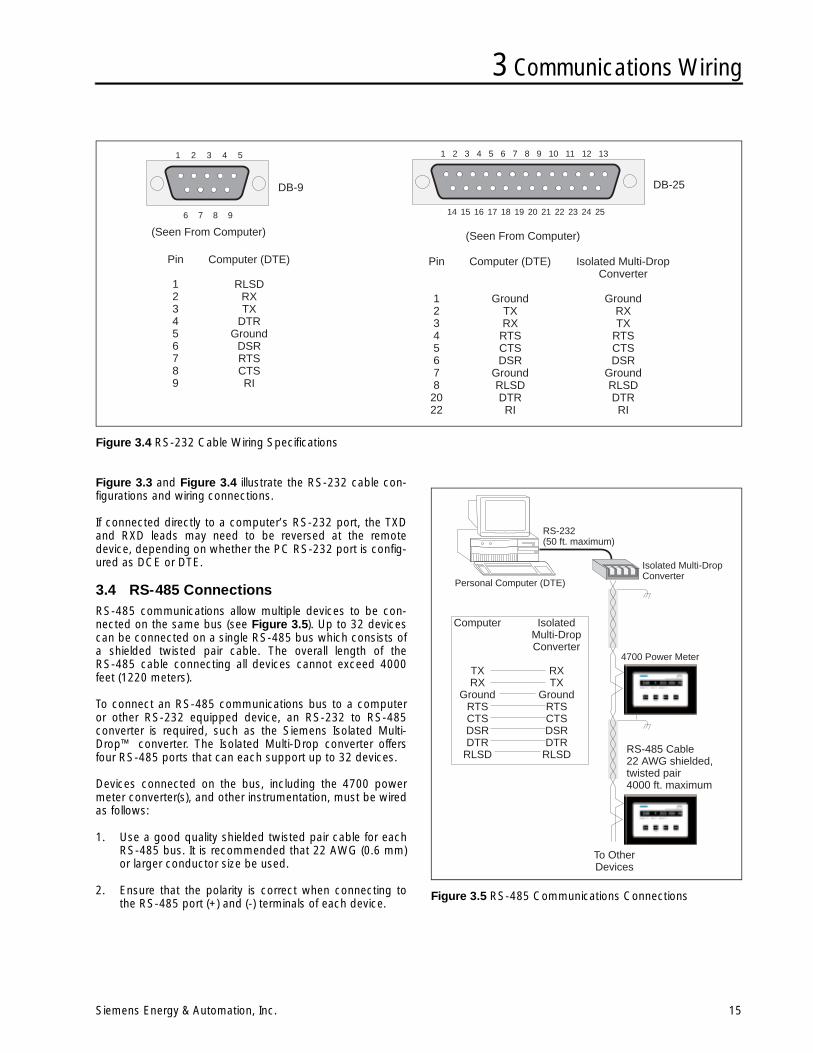
Figure 3.4 RS-232 Cable Wiring Specifications
DB-9 DB-25
1 2 3 4 5
6 7 8 9
1 2 3 4 5 6 7 8 9 10 11 12 13
14 15 16 17 18 19 20 21 22 23 24 25
(Seen From Computer)(Seen From Computer)
Pin
123456789
Pin
12345678
2022
Computer (DTE)
RLSDRXTX
DTRGround
DSRRTSCTSRI
Computer (DTE)
GroundTXRX
RTSCTSDSR
GroundRLSDDTRRI
Isolated Multi-DropConverter
GroundRXTX
RTSCTSDSR
GroundRLSDDTRRI
Figure 3.3 and Figure 3.4 illustrate the RS-232 cable con-figurations and wiring connections.
If connected directly to a computer’s RS-232 port, the TXDand RXD leads may need to be reversed at the remotedevice, depending on whether the PC RS-232 port is config-ured as DCE or DTE.
3.4 RS-485 ConnectionsRS-485 communications allow multiple devices to be con-nected on the same bus (see Figure 3.5). Up to 32 devicescan be connected on a single RS-485 bus which consists ofa shielded twisted pair cable. The overall length of theRS-485 cable connecting all devices cannot exceed 4000feet (1220 meters).
To connect an RS-485 communications bus to a computeror other RS-232 equipped device, an RS-232 to RS-485converter is required, such as the Siemens Isolated Multi-Drop™ converter. The Isolated Multi-Drop converter offersfour RS-485 ports that can each support up to 32 devices.
Devices connected on the bus, including the 4700 powermeter converter(s), and other instrumentation, must be wiredas follows:
1. Use a good quality shielded twisted pair cable for eachRS-485 bus. It is recommended that 22 AWG (0.6 mm)or larger conductor size be used.
2. Ensure that the polarity is correct when connecting tothe RS-485 port (+) and (-) terminals of each device.
Figure 3.5 RS-485 Communications Connections
RS-232(50 ft. maximum)
Isolated Multi-DropConverter
Personal Computer (DTE)
4700 Power Meter
To OtherDevices
RS-485 Cable22 AWG shielded,twisted pair4000 ft. maximum
Computer
TXRX
GroundRTSCTSDSRDTR
RLSD
IsolatedMulti-DropConverter
RXTX
GroundRTSCTSDSRDTR
RLSD
3 Communications Wiring
16 Siemens Energy & Automation, Inc.
3. The shield of each segment of the RS-485 cable mustbe connected to ground at one end only.
Note: Do not connect ground to the shield at bothends of a segment. Doing so allows groundloop currents to flow in the shield, inducingnoise in the communications cable.
4. It is recommended that an intermediate terminal strip beused to connect each device to the bus. This allows theeasy removal of a device for servicing if necessary.
5. Cables should be isolated as much as possible fromsources of electrical noise.
Devices on an RS-485 bus are connected in a point-to-pointconfiguration with the (+) and (-) terminals of each deviceconnected to the associated terminals on the next device.
4 Optional Wiring
Siemens Energy & Automation, Inc. 17
4 Optional WiringIn addition to current and voltage inputs, the 4700 powermeter has connections for status and auxiliary voltage inputs,control relays, and auxiliary current outputs. These additionalconnections add to the functionality of the meter.
4.1 Status InputsThis section describes and illustrates wiring connectionmethods and applications for the status inputs. Section 6.6in Chapter 6 describes the operation of the status inputs.
The 4700 power meter uses a current-sensing technique tomonitor the status of an external dry contact or the presenceof an external voltage as described in the following sections.
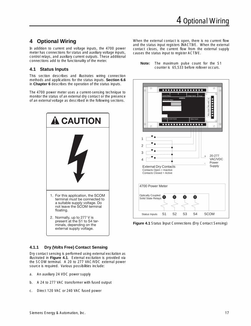
4.1.1 Dry (Volts Free) Contact Sensing
Dry contact sensing is performed using external excitation asillustrated in Figure 4.1. External excitation is provided viathe SCOM terminal. A 20 to 277 VAC/VDC external powersource is required. Various possibilities include:
a. An auxiliary 24 VDC power supply
b. A 24 to 277 VAC transformer with fused output
c. Direct 120 VAC or 240 VAC fused power
When the external contact is open, there is no current flowand the status input registers INACTIVE. When the externalcontact closes, the current flow from the external supplycauses the status input to register ACTIVE.
Note: The maximum pulse count for the S1counter is 65,533 before rollover occurs.
Figure 4.1 Status Input Connections (Dry Contact Sensing)
1
2
3
4
External Dry ContactsContacts Open = InactiveContacts Closed = Active
R R R R
S1 S2 S3 S4 SCOM
Optically CoupledSolid State Relays
Status Inputs
4700 Power Meter
+
-
20-277VAC/VDCPowerSupply
4 Optional Wiring
18 Siemens Energy & Automation, Inc.
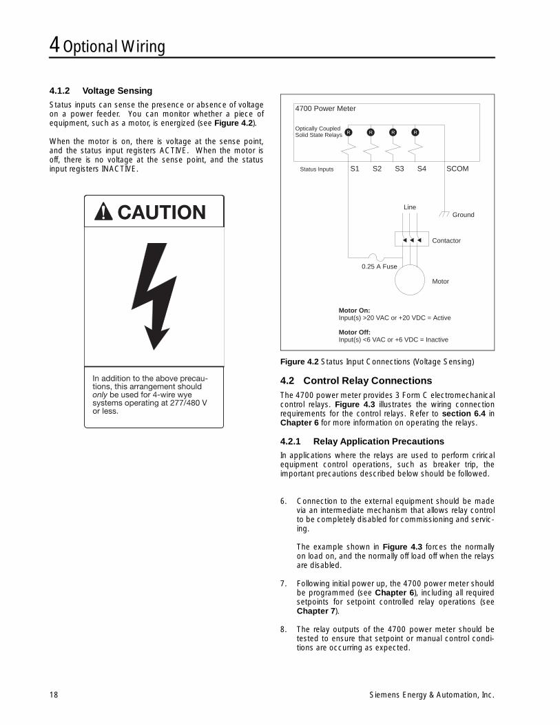
4.1.2 Voltage Sensing
Status inputs can sense the presence or absence of voltageon a power feeder. You can monitor whether a piece ofequipment, such as a motor, is energized (see Figure 4.2).
When the motor is on, there is voltage at the sense point,and the status input registers ACTIVE. When the motor isoff, there is no voltage at the sense point, and the statusinput registers INACTIVE.
Figure 4.2 Status Input Connections (Voltage Sensing)
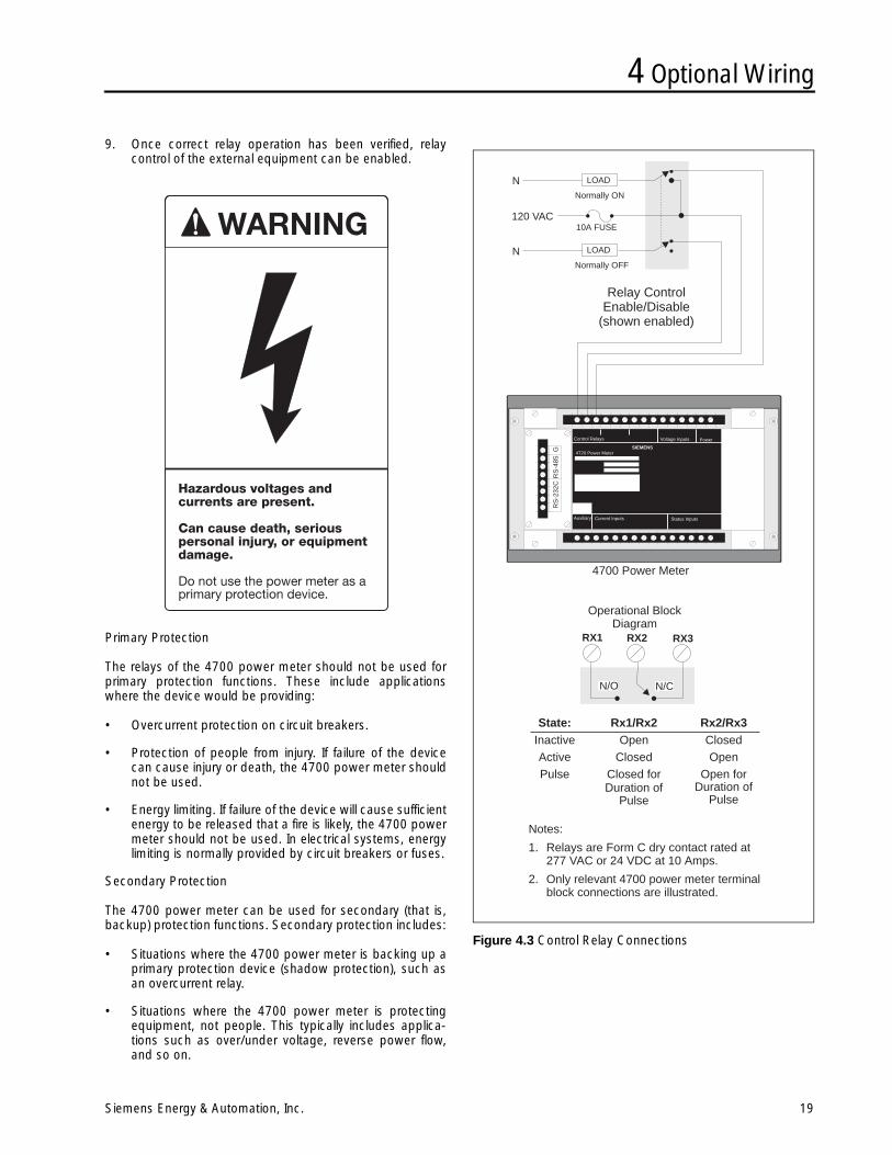
4.2 Control Relay ConnectionsThe 4700 power meter provides 3 Form C electromechanicalcontrol relays. Figure 4.3 illustrates the wiring connectionrequirements for the control relays. Refer to section 6.4 inChapter 6 for more information on operating the relays.
4.2.1 Relay Application Precautions
In applications where the relays are used to perform criricalequipment control operations, such as breaker trip, theimportant precautions described below should be followed.
6. Connection to the external equipment should be madevia an intermediate mechanism that allows relay controlto be completely disabled for commissioning and servic-ing.
The example shown in Figure 4.3 forces the normallyon load on, and the normally off load off when the relaysare disabled.
7. Following initial power up, the 4700 power meter shouldbe programmed (see Chapter 6), including all requiredsetpoints for setpoint controlled relay operations (seeChapter 7).
8. The relay outputs of the 4700 power meter should betested to ensure that setpoint or manual control condi-tions are occurring as expected.
R R R R
S1 S2 S3 S4 SCOM
Optically CoupledSolid State Relays
Status Inputs
4700 Power Meter
Ground
Contactor
Motor
0.25 A Fuse
Line
Motor On:Input(s) >20 VAC or +20 VDC = Active
Motor Off:Input(s) <6 VAC or +6 VDC = Inactive
4 Optional Wiring
Siemens Energy & Automation, Inc. 19
9. Once correct relay operation has been verified, relaycontrol of the external equipment can be enabled.
Primary Protection
The relays of the 4700 power meter should not be used forprimary protection functions. These include applicationswhere the device would be providing:
• Overcurrent protection on circuit breakers.
• Protection of people from injury. If failure of the devicecan cause injury or death, the 4700 power meter shouldnot be used.
• Energy limiting. If failure of the device will cause sufficientenergy to be released that a fire is likely, the 4700 powermeter should not be used. In electrical systems, energylimiting is normally provided by circuit breakers or fuses.
Secondary Protection
The 4700 power meter can be used for secondary (that is,backup) protection functions. Secondary protection includes:
• Situations where the 4700 power meter is backing up aprimary protection device (shadow protection), such asan overcurrent relay.
• Situations where the 4700 power meter is protectingequipment, not people. This typically includes applica-tions such as over/under voltage, reverse power flow,and so on.
Figure 4.3 Control Relay Connections
N
N
Relay ControlEnable/Disable
(shown enabled)
N/O N/C
Operational BlockDiagram
RX1 RX2 RX3
Notes:
1. Relays are Form C dry contact rated at277 VAC or 24 VDC at 10 Amps.
2. Only relevant 4700 power meter terminalblock connections are illustrated.
120 VAC
Normally ON
Normally OFF
10A FUSE
LOAD
LOAD
GR
S-4
85R
S-2
32C
Control Relays Voltage Inputs Power
Auxiliary Current Inputs Status Inputs
4720 Power MeterSIEMENS
4700 Power Meter
State:InactiveActivePulse
Rx1/Rx2Open
ClosedClosed forDuration of
Pulse
Rx2/Rx3ClosedOpen
Open forDuration of
Pulse
4 Optional Wiring
20 Siemens Energy & Automation, Inc.
4.3 Auxiliary Voltage InputFigure 4.4 illustrates two possible wiring connection meth-ods and applications for the VAUX input. Section 6.3.1 inChapter 6 describes the operation of this input.
Note: VAUX is a non-isolated input. If full isolation isrequired, use an intermediate isolationtransducer.
Figure 4.4 Auxiliary Voltage Input Connections
4.4 Auxiliary Current OutputFigure 4.5 illustrates two possible wiring connection meth-ods and applications for the IOUT output. Section 6.3.2 inChapter 6 describes the operation of this input.
Note: IOUT is a non-isolated input. If full isolation isrequired, use an intermediate isolationtransducer.
Figure 4.5 Auxiliary Current Output Connections
TemperatureTransducer
+-
TemperatureProbe
VAux Application: Temperature Sensing
VAux Application: Battery Voltage Sensing
2.3 kΩ1 W
100 Ω1 W
+
-
24 VDCGenerator
StartBattery
Note:Resistors selected togive nominal 1V.
IOut Application: Chart Recorder or RTU Input
IOut Application: Analog Meter
0-20 mADC Meter
0–20 mAor
4–20 mAInput
Chart Recorderor
RTU InputNote:250Ω maximum load
5 Operator Interface
Siemens Energy & Automation, Inc. 21
5 Operator InterfaceThis chapter describes the following:
• Power-up procedure
• Front panel operation and display mode
For a description of the 4700 power meter programmingmode and instructions on how to program the meter, refer toChapter 6, Programming.
5.1 Start UpAfter all installation wiring is complete and has been doublechecked, the unit may be powered up by applying theappropriate voltage to the power input terminals.
The 4700 power meter first enters its display mode, present-ing Volts-Amps-Power Function. The power function dis-played on power up is kW average, totalled for all phases(see Figure 5.1). The values initially appearing may not becorrect, since the unit has not been properly programmedwith the correct information. Refer to Chapter 6, Program-ming, for instructions on how to program the meter.
Figure 5.1 Front Panel Display Modes
5.2 Front Panel OperationThe 4700 power meter provides a unique and very flexibleuser interface. One of its front panel features is the large,high-visibility, 20-character vacuum fluorescent display. Theother feature is the row of four long-life, stainless steel mem-brane buttons for parameter selection and local program-ming functions. See Figure 5.2 for an illustration of the frontpanel of the 4700 power meter.
The display can present a wide variety of information in manydifferent formats. Readings of up to nine digits including anyfloating point decimals can be displayed. The type of infor-mation and formats available are described below.
5.2.1 Standard Phase Display
The front panel display (on power up) presents volts, ampsand power function for the selected phase. The Phase but-ton is used to advance through each phase in sequence,while a selection of power functions can be accessed usingthe Function button. The format of the phase labels andnumeric readings can be programmed to conform to interna-tional conventions (see section 6.3.3).
5.2.2 Full Width Display
Very large measured values (for example, kW hr) and param-eters with large display labels are presented using the entiredisplay.
Note: While viewing a full-width display, press thePhase button to return to the standardVolts-Phase-Amps display.
5.2.3 Three-Phase Displays
Concurrent display of readings for all three phase voltages orcurrents is possible.
5.2.4 Phase Button
The Phase button selects the phase for which the volt andamp values are displayed. The asterisk (*) symbol indicatesthe average volts and amps values are being displayed.
• If VOLTS MODE = 4W-WYE, the Phase button stepsthrough all line-to-neutral values, the line-to-neutralaverage, and all line-to-line values. The line-to-line val-ues are displayed with a comma following the phaseindicator (for example, A,).
• If VOLTS MODE = DELTA, the Phase button stepsthrough all line-to-line values for all the phases, and alsogives the average of the three phases.
• If VOLTS MODE = SINGLE, the Phase button stepsthrough the sequence: A, B, L. An A indicates voltageand current for the A phase. The B indicates voltageand current for the B phase. An L indicates the line-to-line voltage, and also the average of the two line cur-rents.
Standard Phase Display
Full Width Display
Three Phase Display
Volts Amps
Power Functions
PhaseRMS RMS
Indicates 260 Volts, 1700 Amps, and 1241 kW for Phase A
Indicates 29.4 MW for phase A, thermal demand, maximum.
Indicates 483 Volts, phase A, 485 Volts, phase B, and 479 Volts,phase C.
.
5 Operator Interface
22 Siemens Energy & Automation, Inc.
5.2.5 Function Button
A preset list of useful power function parameters is availablevia the Function button. Press the Function button toadvance through each measured parameter.
For per-phase values displayed using the Function button,the Phase button can be used to advance the displaythrough each phase.
The following is the complete sequence of power functionparameters accessible using the Function button:
• kW per phase
• kVAR per phase
• kVA per phase
• Power Factor per phase
• Current I4
• Frequency (phase A)
• kW demand
• Amp demand
• Voltage VAUX
• kW hours
• kVAR hours
5.2.6 Minimum and Maximum Buttons
The Minimum and Maximum buttons display the minimumand maximum values of volts, amps, and power functions asindicated in the list below. Min/Max values are displayed forthree seconds before the real-time display returns. The val-ues displayed are minimums and maximums logged sincethe last CLEAR MAX/MIN? function (see Table 5.1).
Table 5.1 Display Labels for Minimum/Maximum Values
Function Label
kilowatts KW (MW)
kilovolt-amperes KVA (MVA)
kilovolt-amperes (reactive) KQ
power factor PF
frequency HZ
kilowatt-demand KWD (MWD)
amperes-demand AMD
volts (VAUX) VX
fourth current input I4
kilowatt-hours KWHRS
kilovolt-ampere (reactive) hours KVARHRS
Figure 5.2 Front Panel Buttons
Display modebutton functions
Programming modebutton functions
Press and hold Function and Minimumto toggle between Programming andDisplay modes.
Four-digit Volts display
Four-digit Amps display
Five-digit plus three-characterpower display
Phase indicator. Commaindicates line-to-line values.
5 Operator Interface
Siemens Energy & Automation, Inc. 23
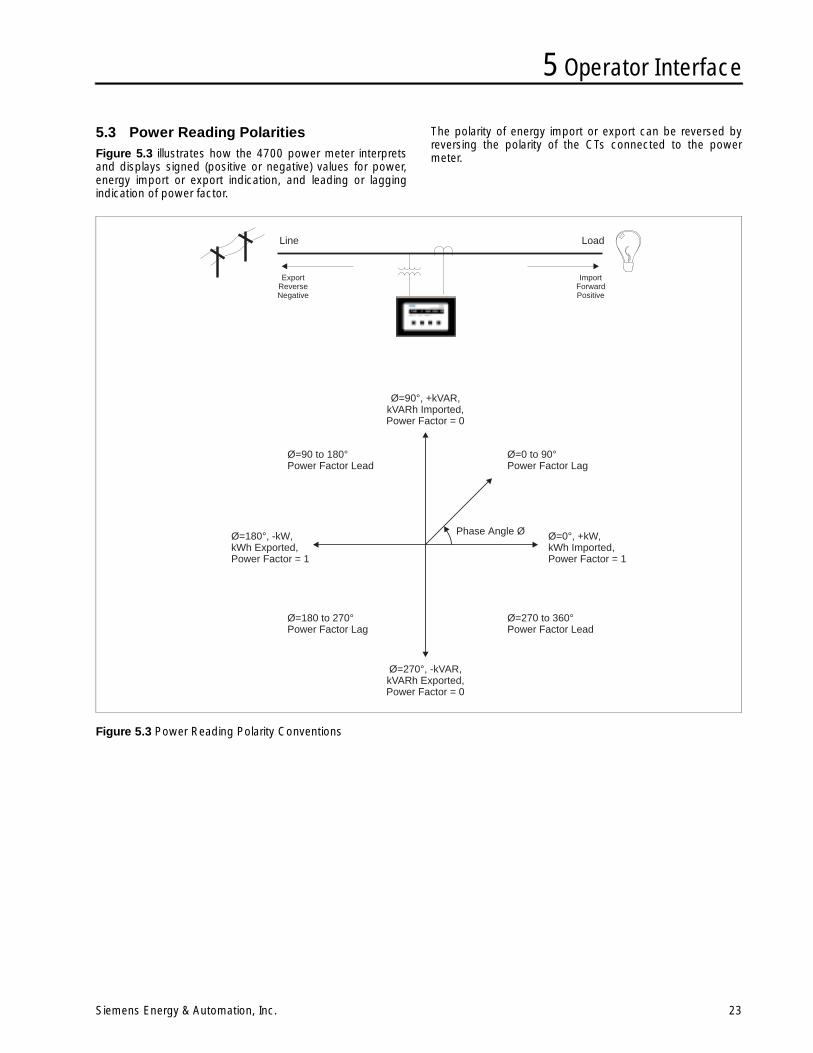
5.3 Power Reading PolaritiesFigure 5.3 illustrates how the 4700 power meter interpretsand displays signed (positive or negative) values for power,energy import or export indication, and leading or laggingindication of power factor.
The polarity of energy import or export can be reversed byreversing the polarity of the CTs connected to the powermeter.
Figure 5.3 Power Reading Polarity Conventions
Phase Angle Ø Ø=0°, +kW,kWh Imported,Power Factor = 1
Ø=180°, -kW,kWh Exported,Power Factor = 1
Ø=270°, -kVAR,kVARh Exported,Power Factor = 0
Ø=90°, +kVAR,kVARh Imported,Power Factor = 0
Ø=0 to 90°Power Factor Lag
Ø=90 to 180°Power Factor Lead
Ø=270 to 360°Power Factor Lead
Ø=180 to 270°Power Factor Lag
Line Load
ExportReverseNegative
ImportForwardPositive

5 Operator Interface
24 Siemens Energy & Automation, Inc.
Notes:
6 Programming
Siemens Energy & Automation, Inc. 25
6 ProgrammingBasic device programming can be performed quickly andeasily from the front panel (called local programming) or viathe communications port using a portable or remotelylocated computer. Basic setup parameters include scalingfactors for the voltage and current inputs, and the voltagemode (wye, delta, and so on). Setup and other critical infor-mation are stored in nonvolatile memory and are not lost ifpower to the unit is turned off. All programming is passwordprotected.
WinPM software fully supports 4700 power meter program-ming, providing a number of parameter screens which makesetup quick and easy. (The open communications protocol ofthe 4700 power meter also allows free access to all pro-gramming parameters using any compatible third-party sys-tem.)
A complete list of all programmable setup parameters is pro-vided in section 6.9.
This manual describes procedures for programming the4700 power meter from its front panel only. For informationon programming via communications using WinPM software,refer to the documentation for WinPM.
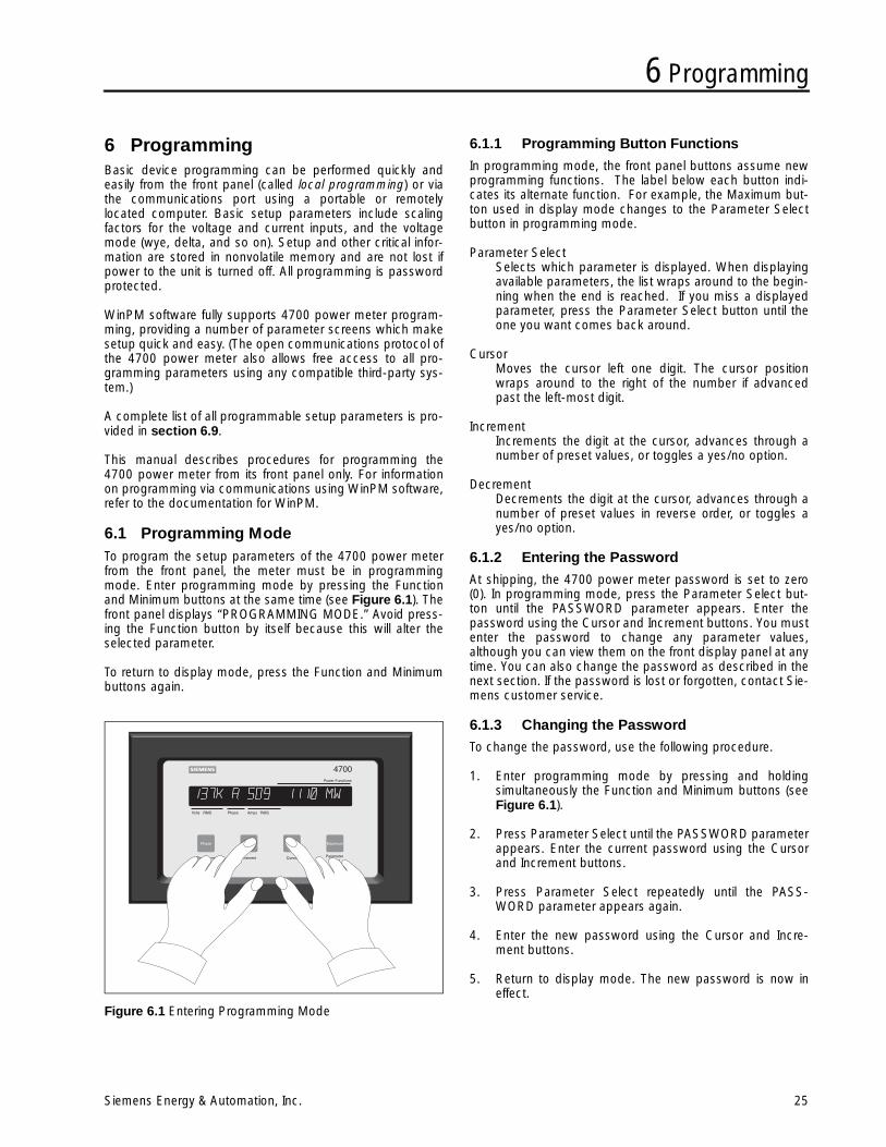
6.1 Programming ModeTo program the setup parameters of the 4700 power meterfrom the front panel, the meter must be in programmingmode. Enter programming mode by pressing the Functionand Minimum buttons at the same time (see Figure 6.1). Thefront panel displays “PROGRAMMING MODE.” Avoid press-ing the Function button by itself because this will alter theselected parameter.
To return to display mode, press the Function and Minimumbuttons again.
Figure 6.1 Entering Programming Mode
6.1.1 Programming Button Functions
In programming mode, the front panel buttons assume newprogramming functions. The label below each button indi-cates its alternate function. For example, the Maximum but-ton used in display mode changes to the Parameter Selectbutton in programming mode.
Parameter SelectSelects which parameter is displayed. When displayingavailable parameters, the list wraps around to the begin-ning when the end is reached. If you miss a displayedparameter, press the Parameter Select button until theone you want comes back around.
CursorMoves the cursor left one digit. The cursor positionwraps around to the right of the number if advancedpast the left-most digit.
IncrementIncrements the digit at the cursor, advances through anumber of preset values, or toggles a yes/no option.
DecrementDecrements the digit at the cursor, advances through anumber of preset values in reverse order, or toggles ayes/no option.
6.1.2 Entering the Password
At shipping, the 4700 power meter password is set to zero(0). In programming mode, press the Parameter Select but-ton until the PASSWORD parameter appears. Enter thepassword using the Cursor and Increment buttons. You mustenter the password to change any parameter values,although you can view them on the front display panel at anytime. You can also change the password as described in thenext section. If the password is lost or forgotten, contact Sie-mens customer service.
6.1.3 Changing the Password
To change the password, use the following procedure.
1. Enter programming mode by pressing and holdingsimultaneously the Function and Minimum buttons (seeFigure 6.1).
2. Press Parameter Select until the PASSWORD parameterappears. Enter the current password using the Cursorand Increment buttons.
3. Press Parameter Select repeatedly until the PASS-WORD parameter appears again.
4. Enter the new password using the Cursor and Incre-ment buttons.
5. Return to display mode. The new password is now ineffect.
6 Programming
26 Siemens Energy & Automation, Inc.
6.1.4 Skipping Over the Setpoint Parameters
If the SETPOINT NUM parameter is 00, and the ParameterSelect button is pressed, the setpoint parameters are passedover.
6.2 Basic SettingsThe VOLT SCALE and AMPS SCALE parameters of the 4700power meter must correspond with the full scale levels thatare to be measured. The scale is the value the meter displayswhen the input is at full scale.
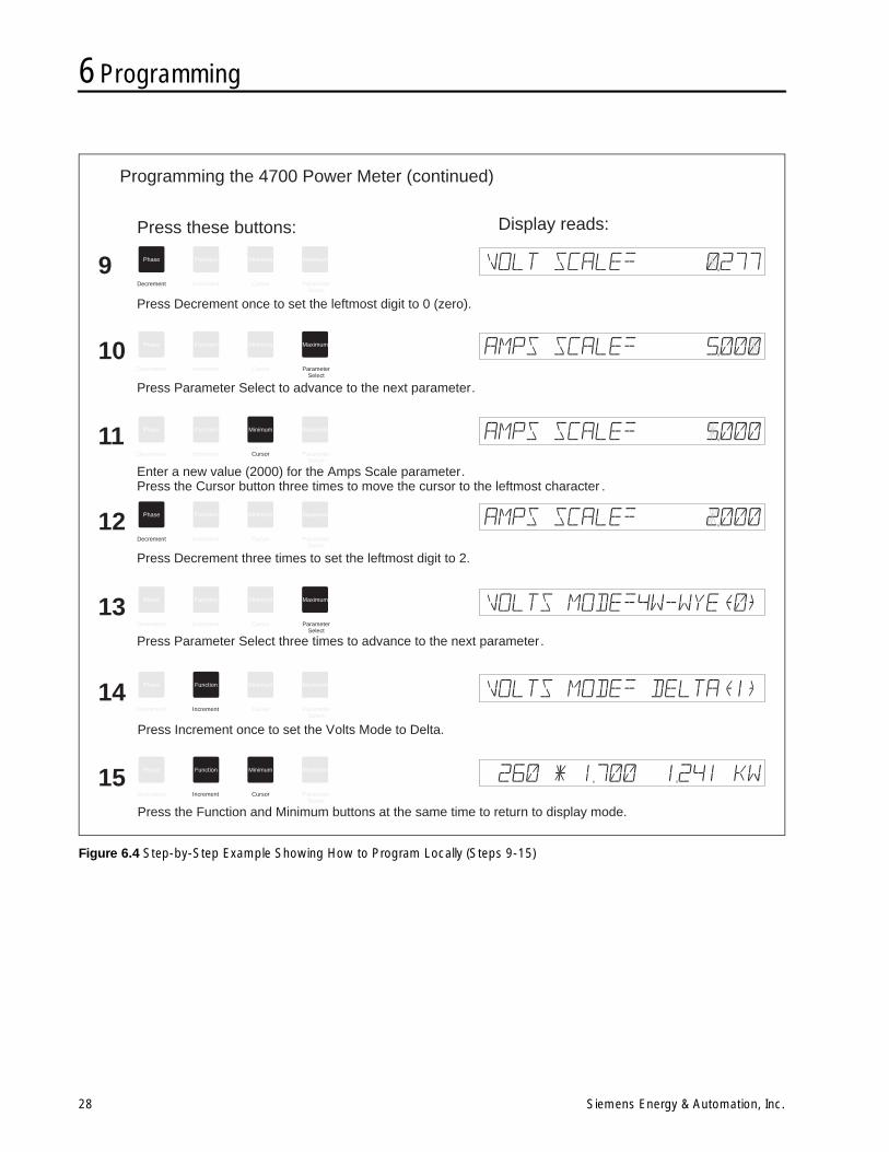
Figure 6.3 and Figure 6.4 show a step-by-step example ofhow to program the operating parameters from the frontpanel. The example given shows how to set the VOLTSMODE to DELTA, the VOLT SCALE to 277, and the AMPSSCALE to 2000.
6.2.1 Volt Scale
In a direct connect configuration, the VOLT SCALE is nor-mally set to 120 for a 120 VAC system, 277 for a 277 VACsystem, or 350 for a 350 VAC system. If VTs are used forconnection to higher voltage systems (using a 120 VACmodel), then set the VOLT SCALE to the primary rating of theVT. Note that this applies only if the VTs’ secondaries arerated at 120 VAC. If not, then the following formula is used todetermine the required VOLT SCALE:
VOLT SCALE = VT Primary Rating x 120 VACVT Secondary Rating
6.2.2 Amps Scale
Set the AMPS SCALE to the primary rating of the CTs used.This applies only if the CTs are rated for a 5 A full scale out-put. If not, the following formula is used to determine therequired AMPS SCALE:
AMPS SCALE = CT Primary Rating x 5A CT Secondary Rating
Note: The fourth CT secondary rating must equalthe phase CTs.
6.2.3 Volts Mode
Set the VOLTS MODE according to the system connectionconfiguration. Refer to Chapter 2, Installation, and to Fig-ure 2.2 through Figure 2.7 for more information.
The VOLTS MODE options are:
4W-WYE, DELTA, SINGLE, DEMO
6.3 Additional Settings
6.3.1 Auxiliary Voltage Input Operation
The 4700 power meter uses an auxiliary voltage input thatallows measurement and display of an external voltage (1VAC/VDC nominal, 1.25 VAC/VDC maximum). The VAUXSCALE parameter specifies what the meter displays with a1.000 VACRMS/VDC full scale input applied.
Note that this 1 V input differs from the 120 V input for V1, V2and V3.
6.3.2 Auxiliary Current Output Operation
The 4700 power meter can include an analog current output,which is programmable to deliver a current proportional toany measured parameter. Maximum load on the current out-put is 250 resistive. The current output is set in program-ming mode. You must set the following parameters:
I OUT KEY This label specifies the measured parameter for whichthe current output is proportional. Table 6.2 shows thelabels for I OUT KEY corresponding to each measuredparameter.
I OUT SCALEThis value specifies the indicated value for the full scaleoutput of IOUT.
I OUT RANGE This value indicates whether the output mode is 0 to 20mA or 4 to 20 mA.
I OUT RANGE = 0 indicates 0 to 20 mA
I OUT RANGE = 1 indicates 4 to 20 mA
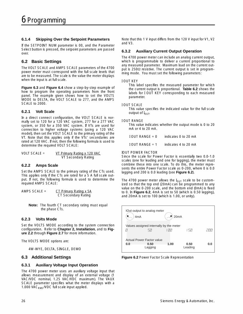
IOUT POWER FACTORSince the scale for Power Factor is essentially two 0.0-1.0scales (one for leading and one for lagging), the meter mustcombine these into one scale. To do this, the meter repre-sents the entire Power Factor scale as 0-200, where 0 is 0.0lagging and 200 is 0.0 leading (see Figure 6.2).
The 4700 power meter allows the IOUT scale to be custom-ized so that the top end (20mA) can be programmed to anyvalue on the 0-200 scale, and the bottom end (0mA) is fixedto 0. In Figure 6.2, 4mA is set to 50 (which is 0.50 lagging),and 20mA is set to 100 (which is 1.00, or unity).
Figure 6.2 Power Factor Scale Representation
Values assigned internally by the meter
Actual Power Factor value0.0 0.50 1.00 0.50 0.0
Lagging Leading
IOut output to analog meter
4mA 20mA
6 Programming
Siemens Energy & Automation, Inc. 27
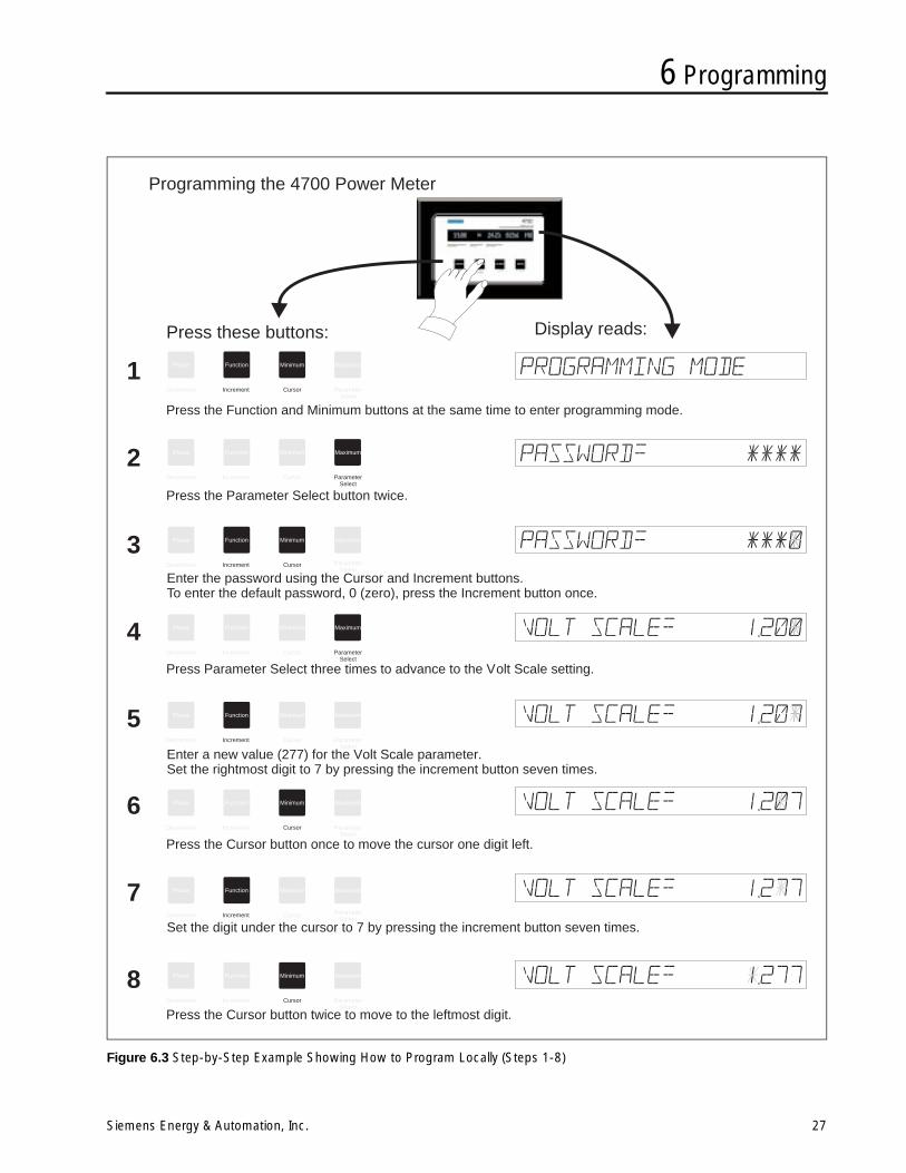
Figure 6.3 Step-by-Step Example Showing How to Program Locally (Steps 1-8)
Press these buttons: Display reads:
Phase
Phase
Phase
Phase
Phase
Phase
Phase
Phase
Function
Function
Function
Function
Function
Function
Function
Function
Minimum
Minimum
Minimum
Minimum
Minimum
Minimum
Minimum
Minimum
Maximum
Maximum
Maximum
Maximum
Maximum
Maximum
Maximum
Maximum
Decrement
Decrement
Decrement
Decrement
Decrement
Decrement
Decrement
Decrement
ParameterSelect
ParameterSelect
ParameterSelect
ParameterSelect
ParameterSelect
ParameterSelect
ParameterSelect
ParameterSelect
Cursor
Cursor
Cursor
Cursor
Cursor
Cursor
Cursor
Cursor
Increment
Increment
Increment
Increment
Increment
Increment
Increment
Increment
Programming the 4700 Power Meter
1
2
3
4
5
6
7
8
Press the Function and Minimum buttons at the same time to enter programming mode.
Press the Parameter Select button twice.
Enter the password using the Cursor and Increment buttons.To enter the default password, 0 (zero), press the Increment button once.
Press Parameter Select three times to advance to the Volt Scale setting.
Enter a new value (277) for the Volt Scale parameter.Set the rightmost digit to 7 by pressing the increment button seven times.
Set the digit under the cursor to 7 by pressing the increment button seven times.
Press the Cursor button once to move the cursor one digit left.
Press the Cursor button twice to move to the leftmost digit.
6 Programming
28 Siemens Energy & Automation, Inc.
Figure 6.4 Step-by-Step Example Showing How to Program Locally (Steps 9-15)
Press these buttons: Display reads:
Phase
Phase
Phase
Phase
Phase
Phase
Phase
Function
Function
Function
Function
Function
Function
Function
Minimum
Minimum
Minimum
Minimum
Minimum
Minimum
Minimum
Maximum
Maximum
Maximum
Maximum
Maximum
Maximum
Maximum
Decrement
Decrement
Decrement
Decrement
Decrement
Decrement
Decrement
ParameterSelect
ParameterSelect
ParameterSelect
ParameterSelect
ParameterSelect
ParameterSelect
ParameterSelect
Cursor
Cursor
Cursor
Cursor
Cursor
Cursor
Cursor
Increment
Increment
Increment
Increment
Increment
Increment
Increment
Programming the 4700 Power Meter (continued)
9
10
11
12
13
14
15
Press Decrement once to set the leftmost digit to 0 (zero).
Enter a new value (2000) for the Amps Scale parameter.Press the Cursor button three times to move the cursor to the leftmost character .
Press Parameter Select to advance to the next parameter.
Press Decrement three times to set the leftmost digit to 2.
Press Increment once to set the Volts Mode to Delta.
Press the Function and Minimum buttons at the same time to return to display mode.
Press Parameter Select three times to advance to the next parameter.
6 Programming
Siemens Energy & Automation, Inc. 29
6.3.3 Display Format
The front panel display can present numeric information andphase labels in formats that reflect various world standards.
The FORMAT parameter allows the user to select formats fornumeric information and phase labels. This parameter is dis-played as:
FORMAT= ABC 1,234.5
The three-letter prefix specifies the phase labels. The possi-ble values are ABC (default), XYZ, RBY and RST.
The five-digit integer specifies the display numbers. The for-mats for possible values are:
a. A comma for the thousands delimiter (radix) and a deci-mal point for the decimal delimiter. Example: 1,234.5This is the default.
b. No thousands delimiter and a comma for the decimaldelimiter. Example: 1234,5
The Cursor button cycles between the phase label parame-ter and display number parameter. The Increment or Decre-ment buttons modify the values for selected parameters.
6.4 Control Relay OperationThe 4700 power meter contains three control relays (R1 toR3), which can be used for a variety of purposes, such asactivation of alarms or load control. Each relay can switchAC loads of up to 120 VAC, and DC loads of up to 24 VDC at10 A. Remote operation of each relay is via the communica-tions port.
The relays are also manipulated by setpoints on selectedmeasured parameters. Setpoint operation is described indetail in Chapter 7, Using Setpoints.
Another use for the control relays is for kVARH and kWHpulsed output. See section 6.4.4 for more information.
Section 4.2 in Chapter 4 shows wiring requirements for thecontrol relays.
6.4.1 Control Relay Modes
You can assign each of the three relays to setpoint operationin latch or pulse mode, or to kVARH or kWH pulsing.
6.4.2 Access to Relay Parameters
The RELAY OPERATION parameter accesses the relayparameters, and also allows you to select which relay to pro-gram. Selecting a value of 0 (zero) skips all relay parameterswhen Parameter Select is pressed. Selecting 1, 2, or 3accesses the programmable parameters for the selectedrelay.
6.4.3 Setpoint Relay Operation
For setpoint operation, the relays function in latch or pulsemode. In latch mode, the relay operates for the duration thatthe assigned setpoint is active (normally open contacts areclosed). In pulse mode, when the setpoint is active, the relayoperates for a specific pulse duration.
Set Rx MODE to SETPOINT for setpoint operation. Set RxVALUE to latch mode (Rx VALUE = 0), or to pulse duration (inseconds) for pulse mode operation.
Note: While you are programming the 4700 powermeter via the front panel or communica-tions, no setpoint-controlled relay opera-tions occur until you complete theprogramming sequence. The 4700 powermeter then assesses the status of each set-point and performs any required operations.
6.4.4 kVARH and kWH Pulse Operation
When a relay is configured for kVARH or kWH pulse opera-tion, the pulses are based on the total energy imported (for-ward) and exported (reverse). Set Rx MODE to KVARHPULSE or KWH PULSE. In these modes, use Rx HRS/PULSE to set the number of unit-hours between pulses.
Note: A relay configured for energy pulsing will notrespond to an assigned setpoint thatbecomes active. Maximum pulse rate forthe relays is 1 pulse every 2 seconds (0.5Hz).
6.4.5 Manual Forced Relay Operations
You can force operate or release relays by commands via thecommunications port. Manual forced operate and forcedrelease commands override any present setpoint condition.Forced operate commands made via communications affectonly a setpoint relay (Rx MODE = SETPOINT).
If the relay is in pulse mode (Rx VALUE > 0), a forced operatecommand initiates a pulse of length equivalent to the valueset by the Rx VALUE parameter for that relay. This operationis recorded in the event log and indicates that the relay waspulsed. A forced release command has no effect.
If the relay is in latch mode (Rx VALUE = 0), it behaves nor-mally for forced operate, forced release, and return to normal(return to setpoint control) commands.
See section 6.4.7 for manual relay control special cases.
6 Programming
30 Siemens Energy & Automation, Inc.
6.4.6 Relay Event Logging
For a relay assigned to setpoint operation (Rx MODE = SET-POINT), the event log records relay operations in one of twoways, depending on whether the relay is set to operate inlatch or pulse mode.
a. Pulse mode (Rx VALUE > 0): The event log shows thatthe relay is pulsed when the setpoint becomes active.When the setpoint returns to its inactive state, the set-point event is logged but does not indicate the relay ispulsed, since no pulse is generated.
b. Latch mode (Rx VALUE = 0): The event log records thatthe relay is operated (ON) when the setpoint becomesactive, and is released (OFF) when the setpoint returnsto an inactive state.
If the relay is configured for kVARH or kWH pulse mode, norelay operations are recorded in the event log.
6.4.7 Manual Relay Command Special Cases
If a manual forced operate command for a selected relay isreceived while that relay is already in a forced operated state,then the relay command is ignored and is not logged. This isalso true for a forced release command sent to a relayalready in a forced released state. In addition, manual relaycommands sent to relays in kVARH or kWH pulse mode arenot logged.
6.4.8 Relay Operation After Power Outages
When the power feed to the 4700 power meter is inter-rupted, even momentarily, the output relays are released.When power is restored, the meter allows a three-secondsettling time, then reevaluates setpoint conditions. If appro-priate, the relays operate after the programmed time delays.
Any forced operated or forced released relay is released, fol-lowed by a resumption of normal setpoint operation.
6.5 Bi-Directional EnergyEnergy measurements represent the KWH or KVARH sumsfor all three phases. Energy parameters provide three mea-surement modes that indicate bi-directional power flow: for-ward, reverse, and total. KWH and KVARH can provide allthree modes.
Total energy measurements represent the sum of the abso-lute values of imported and exported energy. Total energyvalues are incremented by energy that is imported orexported.
Imported real or reactive energy is displayed with an F suffix(kWH-F, kVARH-F), indicating forward flow. Exported energyvalues are displayed with an R suffix (kWH-R, kVARH-R),indicating reverse flow.
Note: Only kWH-F/kWH-R and kVARH-F/kVARH-R measurements are displayedfrom the front panel. kWH and kVARHtotal values are read only via communi-cations.
6.6 Status Input OperationThe 4700 power meter provides four optional status inputs(S1 to S4), which are used to sense the state of an externalcontact. If the input voltage is below 9 VAC or VDC, theinput is sensed as inactive. If it is over 20 VAC or VDC, it issensed as active.
The status of these inputs is viewed using a Power Monitordisplay and monitoring unit (or a computer runningWinPM,SIEServe, or other supervisory software) connectedto the communications port.
You can program the Status Input #4 (S4) to initiate kWDemand Synchronization. See Chapter 8, Demand Calcu-lation, for more information.
The 4700 power meter maintains a counter for the StatusInput #1 (S1). The counter accurately follows a maximum fre-quency of 0.3 Hz and can be reset to zero via the communi-cations port. A minimum pulse width of 40 milliseconds isrequired for reliable sensing of status input changes.
Note: The maximum pulse count for the S1counter is 65,535 before rollover occurs.
Section 4.1 in Chapter 4 shows several wiring diagramsillustrating connections for the status inputs.
6.7 Fourth Current Input OperationThe 4700 power meter includes an optional fourth currentinput, designated I4. The input uses connections I41 and I42on the terminal strip. The AMPS SCALE parameter sets thescaling for all four current inputs. Therefore, the CT primaryrating of the I4 current input must be the same as the CT pri-mary ratings for the three-phase current inputs (5 A nomi-nally).
Normally, this input is used to measure current in the neutralconductor. In installations with nonlinear loads, odd harmon-ics can fail to cancel, producing significant currents in theneutral conductor.
The I4 reading is viewed from the front panel by pressing theFunction button until displayed. It is also viewable remotely.
6.8 Waveform CaptureDigital waveform capture capabilities are used for detailedpower quality analysis.
Waveform capture allows the user to perform high-speedsampling of the V1, V2, V3, VAUX, I1, I2, I3, or I4 (neutral cur-rent) inputs. One full cycle of the signal at a single input issampled at a rate of 128 samples per cycle. All samples aretaken in sync with the communications line frequency, andwithin one input cycle.
Sampled waveform data is stored in on-board memory andis read via the communications port. The high sampling rateproduces high-resolution data, which allows analysis of fre-quency components to the 63rd harmonic.
6 Programming
Siemens Energy & Automation, Inc. 31
You can upload captured waveform data to a master com-puter to display the waveforms and perform Fast FourierTransforms on them. This provides an indication of total har-monic distortion and a breakdown of individual frequencycomponents.
From the master computer, the operator requests the cap-ture of individually selected 4700 power meter inputs. Thecomputer then uploads the waveform data. Waveform cap-ture is automatically reinitiated when the 4700 power meteron-board memory is read via the communications port.
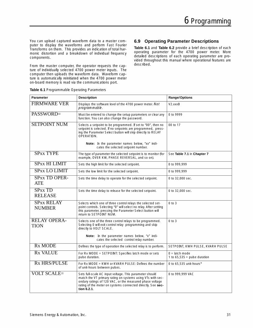
6.9 Operating Parameter DescriptionsTable 6.1 and Table 6.2 provide a brief description of eachoperating parameter for the 4700 power meter. Moredetailed descriptions of each operating parameter are pro-vided throughout this manual where operational features aredescribed.
Table 6.1 Programmable Operating Parameters
Parameter Description Range/Options
FIRMWARE VER Displays the software level of the 4700 power meter. Not programmable.
V2.xxxB
PASSWORD= Must be entered to change the setup parameters or clear any function. You can also change the password.
0 to 9999
SETPOINT NUM Selects a setpoint to be programmed. If set to “00”, then no setpoint is selected. If no setpoints are programmed, press-ing the Parameter Select button will skip directly to RELAY OPERATION.
Note: In the parameter names below, “xx” indi-cates the selected setpoint number.
00 to 17
SPxx TYPE The type of parameter the selected setpoint is to monitor (for example, OVER KW, PHASE REVERSAL, and so on).
See Table 7.1 in Chapter 7
SPxx HI LIMIT Sets the high limit for the selected setpoint. 0 to 999,999
SPxx LO LIMIT Sets the low limit for the selected setpoint. 0 to 999,999
SPxx TD OPER-ATE
Sets the time delay to operate for the selected setpoint. 0 to 32,000 sec.
SPxx TDRELEASE
Sets the time delay to release for the selected setpoint. 0 to 32,000 sec.
SPxx RELAYNUMBER
Selects which one of three control relays the selected set-point controls. Selecting “0” will select no relay. After setting this parameter, pressing the Parameter Select button will return to SETPOINT NUM.
0 to 3
RELAY OPERA-TION
Selects one of the three control relays to be programmed. Selecting 0 will exit control relay programming and skip directly to VOLT SCALE.
Note: In the parameter names below, “x” indi-cates the selected control relay number.
0 to 3
Rx MODE Defines the type of operation the selected relay is to perform. SETPOINT, KWH PULSE, KVARH PULSE
Rx VALUE For Rx MODE = SETPOINT: Specifies latch mode or sets pulse duration.
0 = latch mode1 to 65,535 = pulse duration
Rx HRS/PULSE For Rx MODE = KWH or KVARH PULSE: Defines the number of unit-hours between pulses.
0 to 65,535 unit-hours*
VOLT SCALE= Sets full-scale AC input voltage. This parameter should match the VT primary rating on systems using VTs with sec-ondary ratings of 120 VAC, or the measured phase voltage rating of the meter on systems connected directly. See sec-tion 6.2.1.
0 to 999,999 VAC

6 Programming
32 Siemens Energy & Automation, Inc.
AMPS SCALE= Sets full-scale AC input current. This parameter should match the CT primary rating when the secondary rating is 5 A. See section 6.2.2.
0 to 9,999 A
* For Rx MODE = KWHR PULSE or KVARH PULSE, pulse duration is 1 second.
Table 6.1 Programmable Operating Parameters
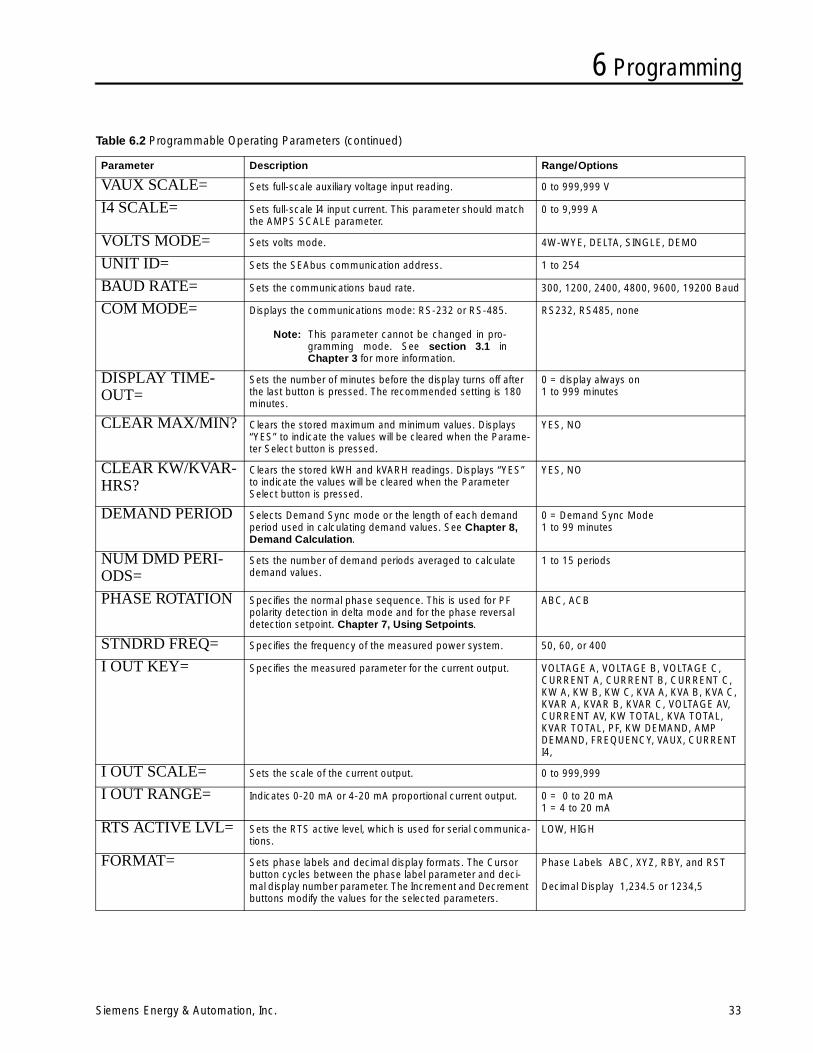
6 Programming
Siemens Energy & Automation, Inc. 33
Table 6.2 Programmable Operating Parameters (continued)
Parameter Description Range/Options
VAUX SCALE= Sets full-scale auxiliary voltage input reading. 0 to 999,999 V
I4 SCALE= Sets full-scale I4 input current. This parameter should match the AMPS SCALE parameter.
0 to 9,999 A
VOLTS MODE= Sets volts mode. 4W-WYE, DELTA, SINGLE, DEMO
UNIT ID= Sets the SEAbus communication address. 1 to 254
BAUD RATE= Sets the communications baud rate. 300, 1200, 2400, 4800, 9600, 19200 Baud
COM MODE= Displays the communications mode: RS-232 or RS-485.
Note: This parameter cannot be changed in pro-gramming mode. See section 3.1 inChapter 3 for more information.
RS232, RS485, none
DISPLAY TIME-OUT=
Sets the number of minutes before the display turns off after the last button is pressed. The recommended setting is 180 minutes.
0 = display always on 1 to 999 minutes
CLEAR MAX/MIN? Clears the stored maximum and minimum values. Displays “YES” to indicate the values will be cleared when the Parame-ter Select button is pressed.
YES, NO
CLEAR KW/KVAR-HRS?
Clears the stored kWH and kVARH readings. Displays “YES” to indicate the values will be cleared when the Parameter Select button is pressed.
YES, NO
DEMAND PERIOD Selects Demand Sync mode or the length of each demand period used in calculating demand values. See Chapter 8, Demand Calculation.
0 = Demand Sync Mode 1 to 99 minutes
NUM DMD PERI-ODS=
Sets the number of demand periods averaged to calculate demand values.
1 to 15 periods
PHASE ROTATION Specifies the normal phase sequence. This is used for PF polarity detection in delta mode and for the phase reversal detection setpoint. Chapter 7, Using Setpoints.
ABC, ACB
STNDRD FREQ= Specifies the frequency of the measured power system. 50, 60, or 400
I OUT KEY= Specifies the measured parameter for the current output. VOLTAGE A, VOLTAGE B, VOLTAGE C, CURRENT A, CURRENT B, CURRENT C, KW A, KW B, KW C, KVA A, KVA B, KVA C, KVAR A, KVAR B, KVAR C, VOLTAGE AV, CURRENT AV, KW TOTAL, KVA TOTAL, KVAR TOTAL, PF, KW DEMAND, AMP DEMAND, FREQUENCY, VAUX, CURRENT I4,
I OUT SCALE= Sets the scale of the current output. 0 to 999,999
I OUT RANGE= Indicates 0-20 mA or 4-20 mA proportional current output. 0 = 0 to 20 mA 1 = 4 to 20 mA
RTS ACTIVE LVL= Sets the RTS active level, which is used for serial communica-tions.
LOW, HIGH
FORMAT= Sets phase labels and decimal display formats. The Cursor button cycles between the phase label parameter and deci-mal display number parameter. The Increment and Decrement buttons modify the values for the selected parameters.
Phase Labels ABC, XYZ, RBY, and RST
Decimal Display 1,234.5 or 1234,5

6 Programming
34 Siemens Energy & Automation, Inc.
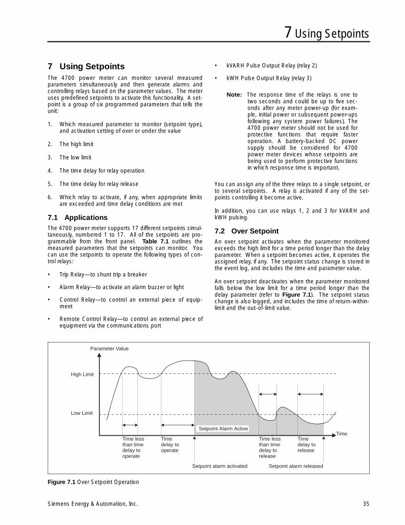
7 Using Setpoints
Siemens Energy & Automation, Inc. 35
7 Using SetpointsThe 4700 power meter can monitor several measuredparameters simultaneously and then generate alarms andcontrolling relays based on the parameter values. The meteruses predefined setpoints to activate this functionality. A set-point is a group of six programmed parameters that tells theunit:
1. Which measured parameter to monitor (setpoint type),and activation setting of over or under the value
2. The high limit
3. The low limit
4. The time delay for relay operation
5. The time delay for relay release
6. Which relay to activate, if any, when appropriate limitsare exceeded and time delay conditions are met
7.1 ApplicationsThe 4700 power meter supports 17 different setpoints simul-taneously, numbered 1 to 17. All of the setpoints are pro-grammable from the front panel. Table 7.1 outlines themeasured parameters that the setpoints can monitor. Youcan use the setpoints to operate the following types of con-trol relays:
• Trip Relay—to shunt trip a breaker
• Alarm Relay—to activate an alarm buzzer or light
• Control Relay—to control an external piece of equip-ment
• Remote Control Relay—to control an external piece ofequipment via the communications port
• kVARH Pulse Output Relay (relay 2)
• kWH Pulse Output Relay (relay 3)
Note: The response time of the relays is one totwo seconds and could be up to five sec-onds after any meter power-up (for exam-ple, initial power or subsequent power-upsfollowing any system power failures). The4700 power meter should not be used forprotective functions that require fasteroperation. A battery-backed DC powersupply should be considered for 4700power meter devices whose setpoints arebeing used to perform protective functionsin which response time is important.
You can assign any of the three relays to a single setpoint, orto several setpoints. A relay is activated if any of the set-points controlling it become active.
In addition, you can use relays 1, 2 and 3 for kVARH andkWH pulsing.
7.2 Over SetpointAn over setpoint activates when the parameter monitoredexceeds the high limit for a time period longer than the delayparameter. When a setpoint becomes active, it operates theassigned relay, if any. The setpoint status change is stored inthe event log, and includes the time and parameter value.
An over setpoint deactivates when the parameter monitoredfalls below the low limit for a time period longer than thedelay parameter (refer to Figure 7.1). The setpoint statuschange is also logged, and includes the time of return-within-limit and the out-of-limit value.
Figure 7.1 Over Setpoint Operation
Parameter Value
High Limit
Low Limit
TimeSetpoint Alarm Active
Time lessthan timedelay tooperate
Time lessthan timedelay torelease
Timedelay tooperate
Setpoint alarm activated Setpoint alarm released
Timedelay torelease
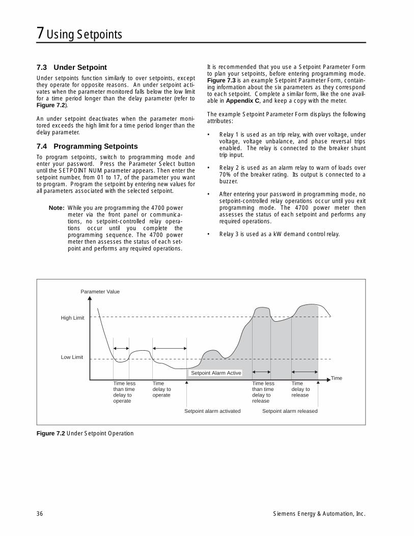
7 Using Setpoints
36 Siemens Energy & Automation, Inc.
7.3 Under SetpointUnder setpoints function similarly to over setpoints, exceptthey operate for opposite reasons. An under setpoint acti-vates when the parameter monitored falls below the low limitfor a time period longer than the delay parameter (refer toFigure 7.2).
An under setpoint deactivates when the parameter moni-tored exceeds the high limit for a time period longer than thedelay parameter.
7.4 Programming SetpointsTo program setpoints, switch to programming mode andenter your password. Press the Parameter Select buttonuntil the SETPOINT NUM parameter appears. Then enter thesetpoint number, from 01 to 17, of the parameter you wantto program. Program the setpoint by entering new values forall parameters associated with the selected setpoint.
Note: While you are programming the 4700 powermeter via the front panel or communica-tions, no setpoint-controlled relay opera-tions occur until you complete theprogramming sequence. The 4700 powermeter then assesses the status of each set-point and performs any required operations.
It is recommended that you use a Setpoint Parameter Formto plan your setpoints, before entering programming mode.Figure 7.3 is an example Setpoint Parameter Form, contain-ing information about the six parameters as they correspondto each setpoint. Complete a similar form, like the one avail-able in Appendix C, and keep a copy with the meter.
The example Setpoint Parameter Form displays the followingattributes:
• Relay 1 is used as an trip relay, with over voltage, undervoltage, voltage unbalance, and phase reversal tripsenabled. The relay is connected to the breaker shunttrip input.
• Relay 2 is used as an alarm relay to warn of loads over70% of the breaker rating. Its output is connected to abuzzer.
• After entering your password in programming mode, nosetpoint-controlled relay operations occur until you exitprogramming mode. The 4700 power meter thenassesses the status of each setpoint and performs anyrequired operations.
• Relay 3 is used as a kW demand control relay.
Figure 7.2 Under Setpoint Operation
Parameter Value
High Limit
Low Limit
TimeTime lessthan timedelay tooperate
Time lessthan timedelay torelease
Timedelay tooperate
Timedelay torelease
Setpoint Alarm Active
Setpoint alarm activated Setpoint alarm released
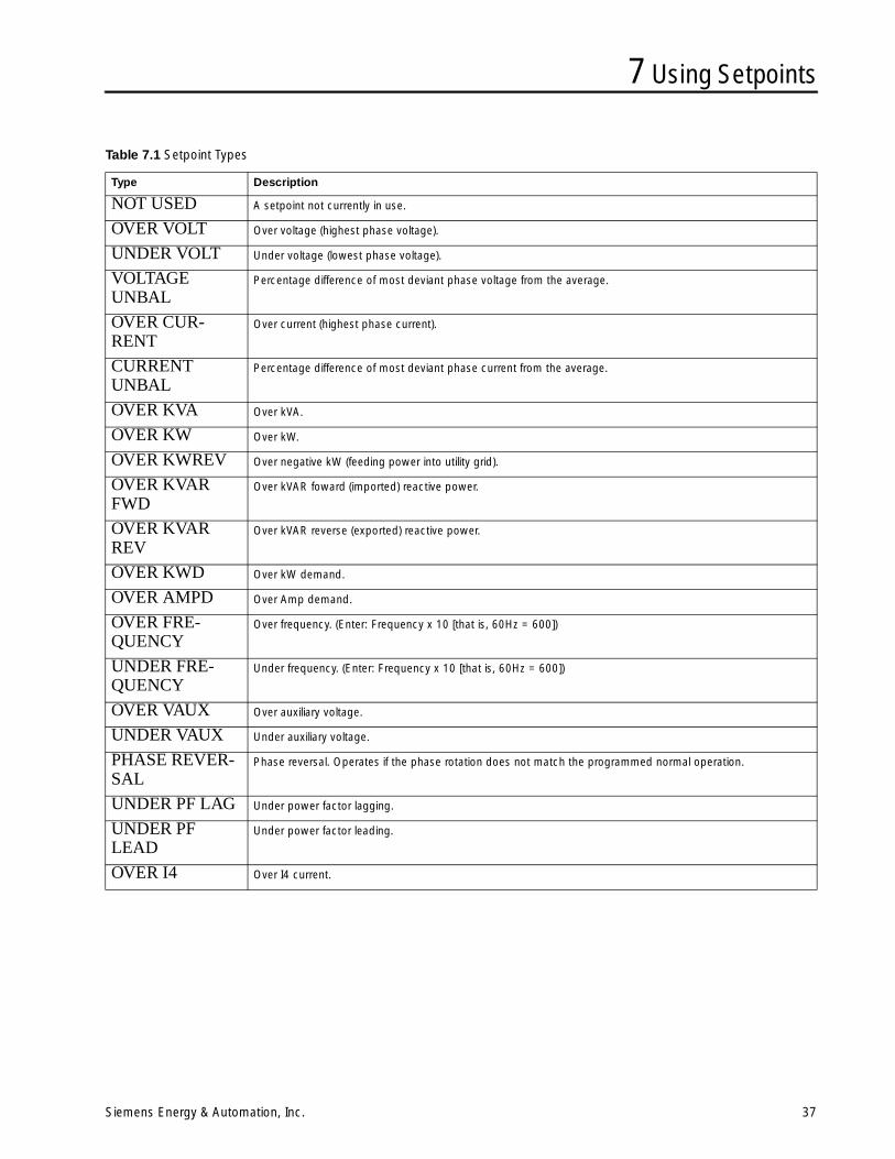
7 Using Setpoints
Siemens Energy & Automation, Inc. 37
Table 7.1 Setpoint Types
Type Description
NOT USED A setpoint not currently in use.
OVER VOLT Over voltage (highest phase voltage).
UNDER VOLT Under voltage (lowest phase voltage).
VOLTAGEUNBAL
Percentage difference of most deviant phase voltage from the average.
OVER CUR-RENT
Over current (highest phase current).
CURRENTUNBAL
Percentage difference of most deviant phase current from the average.
OVER KVA Over kVA.
OVER KW Over kW.
OVER KWREV Over negative kW (feeding power into utility grid).
OVER KVARFWD
Over kVAR foward (imported) reactive power.
OVER KVARREV
Over kVAR reverse (exported) reactive power.
OVER KWD Over kW demand.
OVER AMPD Over Amp demand.
OVER FRE-QUENCY
Over frequency. (Enter: Frequency x 10 [that is, 60Hz = 600])
UNDER FRE-QUENCY
Under frequency. (Enter: Frequency x 10 [that is, 60Hz = 600])
OVER VAUX Over auxiliary voltage.
UNDER VAUX Under auxiliary voltage.
PHASE REVER-SAL
Phase reversal. Operates if the phase rotation does not match the programmed normal operation.
UNDER PF LAG Under power factor lagging.
UNDER PFLEAD
Under power factor leading.
OVER I4 Over I4 current.
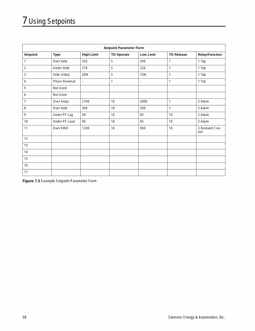
7 Using Setpoints
38 Siemens Energy & Automation, Inc.
Figure 7.3 Example Setpoint Parameter Form
Setpoint Parameter Form
Setpoint Type High Limit TD Operate Low Limit TD Release Relay/Function
1 Over Volts 332 5 290 1 1 Trip
2 Under Volts 270 5 220 1 1 Trip
3 Volts Unbal. 30% 5 10% 1 1 Trip
4 Phase Reversal - 1 - 1 1 Trip
5 Not Used
6 Not Used
7 Over Amps 2100 10 2000 1 2 Alarm
8 Over Volts 300 10 290 1 2 Alarm
9 Under PF Lag 90 10 85 10 2 Alarm
10 Under PF Lead 90 10 85 10 2 Alarm
11 Over KWD 1200 10 900 10 3 Demand Con-trol
12
13
14
15
16
17
8 Demand Calculation
Siemens Energy & Automation, Inc. 39
8 Demand CalculationPower utilities generally bill commercial customers based onboth their energy consumption (in kWhr) and their peakusage levels, called peak demand (in kW). Demand is ameasure of average power consumption over a fixed timeperiod, typically 30 minutes. Peak demand is the highestdemand level recorded over a specific billing period.
8.1 Demand Measurement MethodsDemand measurement methods, and their intervals, varyaccording to individual utilities. Some common methodsinclude: thermal averaging, the fixed interval technique, andthe sliding window technique.
In thermal averaging, the demand indicator responds toheating of a thermal element in the watt hour meter. Thedemand period is determined by the thermal time constantof the element, typically 15 to 30 minutes.
The fixed interval technique measures average usage elec-tronically over each period. The highest recorded value is thepeak demand.
The sliding window technique, or “rolling interval” method,divides the demand interval into subperiods and the demandis measured electronically, based on the average load levelover the most recent set of subperiods. This has the effectof improving the response times, in comparison with thefixed interval method. For example, with a 6x5 minute (30minute total) sliding window, demand is the average powerconsumption over the last six five-minute periods.
8.2 Internally Timed Demand MeasurementThe 4700 power meter uses the sliding window method tomeasure demand. You can program both the DEMANDPERIOD (1 to 99 minutes) and NUM DMD PERIODS (1 to 15)for averaging. This allows you to match virtually any utilitydemand measurement method. Refer to Table 8.1 for moreinformation.
8.3 Demand SynchronizationThe 4700 power meter includes the option of startingdemand intervals that correspond to an active pulse. Set theDEMAND PERIOD parameter to zero, which initiates theDemand Sync mode. Instead of internally timing the durationof each demand period used in the kW demand calculation,the meter looks for an ACTIVE pulse on Status Input #4 (S4).You can still specify the number of demand periods in thismode, as previously explained.
Note: With the fixed interval method, the 4700power meter maximum reading and theutility reading are not necessarily the same,unless the demand periods are time-syn-chronized. The best way to resolve thisproblem is to use the sliding windowmethod with the same total demand periodas the utility, as shown above. The 4700power meter maximum demand reading isthen always equal to or slightly higher thanthe utility readings.
Table 8.1 Demand Calculation Chart
Utility Method 4700 Programming
Demand Period (in minutes)
Number of Demand Periods (must be 15 or less)
Fixed Interval Utility Period 1
Fixed Interval Emulation
Utility Period/15 15
Thermal Utility Period/15 15
Sliding Window Utility Subperiod Utility number of subperiods
8 Demand Calculation
40 Siemens Energy & Automation, Inc.
Notes:
9 Communications
Siemens Energy & Automation, Inc. 41
9 Communications
9.1 GeneralThe 4700 power meter is optionally equipped with a commu-nications card that allows the 4700 power meter to be inte-grated with large energy monitoring networks. Thecommunications port is optically isolated and transient pro-tected. It is field-configurable for RS-232 or RS-485 stan-dards and can operate at data rates up to 19,200 baud.
The 4700 power meter is fully compatible with SiemensWinPM software. WinPM software can display all measuredparameters and status information, waveform data, and datalogs provided by the 4700 power meter. WinPM softwarecan also be used to remotely program the setup parametersfor all basic and advanced features.
The open communications protocol of the 4700 power meterallows access to all data and setup parameters by third-partysystems.
This chapter provides additional information regardingremote communications connections, programming, andgeneral operation.
9.2 RS-232 CommunicationsRS-232 is commonly used for short distance, point-to-pointcommunications. Connection between a host computer (orPLC) and a single remote device must be less than 50 feet.Figure 3.3 and Figure 3.4 in Chapter 3 provide wiring dia-grams for direct RS-232 connection and the required wiringfor the RS-232 interconnect cable(s).
Connection using modems via dedicated or dial-up tele-phone lines is also possible (see Figure 9.1).
When using a modem, it is important that the computer-to-modem and modem-to-4700 power meter cable connec-tions illustrated in Figure 3.4 in Chapter 3 are used.
The RS-232 port RTS line is operational and can be used ifrequired by any hardware device connected to the 4700power meter. Siemens WinPM software does not require theuse of the RTS line for direct RS-232 connections; however,some types of modems (for example, radio modems) mayrequire its operation.
The RTS signal is asserted before the beginning of a trans-mission and remains asserted throughout the transmission.The time delay between the assertion of the RTS and thestart of the transmission is controlled by the TRANSMITDELAY parameter, which can be set from the front panel. Therange is 0 to 999 milliseconds (with 0 (zero) as default).
The programmable RTS ACTIVE LVL parameter selectswhether the RTS line is asserted HIGH or LOW during trans-mission.
9.3 RS-485 CommunicationsRS-485 is used when multiple devices are installed at aremote site. RS-485 communications can be used to con-currently connect up to 32 remote devices on a single com-munications loop. Each device is given a unique unit ID(identification number). In this way, each remote device maybe monitored and controlled from one location by a singlesupervisory device.
The total distance limitation on a single RS-485 communica-tions network is 4000 feet (1220 meters) using 22 AWGtwisted pair shielded cable. Figure 3.5 in Chapter 3 pro-vides a wiring diagram for RS-485 network connection.
Communication methods between the remote RS-485 siteand the supervisory device can include a direct RS-485 con-nection, telephone lines with modems, fiber-optic and/orradio links. An RS-232 to RS-485 converter, such as the Iso-lated Multi-Drop converter, is required between the RS-232port of the computer or modem and the RS-485 network asillustrated in Figure 3.5 in Chapter 3.
9.4 Setting the Unit ID and Baud RateBefore communication with the host computer/PLC is possi-ble, ensure that the 4700 power meter, and all other con-nected devices, are configured for the requiredcommunications standard (RS-232 or RS-485). Instructionsfor the 4700 power meter communications card configura-tion are provided in Figure 3.1 in Chapter 3.
The next step is to program the communication parametersof the 4700 power meter and all other connected devices.The UNIT ID and BAUD RATE parameters of the 4700 powermeter can be programmed via the front panel. The unit IDmust be set to a unique value between 1 and 254. The baudrate of each device on the network must be set to corre-spond with the baud rate selected for the computer. Optionsinclude 300, 1200, 2400, 4800, 9600 or 19,200 baud.
When using a modem interface between the host computerand any remote device(s), ensure that the host computer isnot used to set the BAUD RATE parameter of any selecteddevice outside the working range of the modem. Doing sowill cause that meter to cease communicating. Re-establish-ing communications with that meter is then only possiblethrough the following steps:
1. Reset the baud rate of the remote device from its frontpanel to a value within the working range of the modem.
2. Set the computer to communicate at the baud rate atwhich the remote device has been set to communicate.
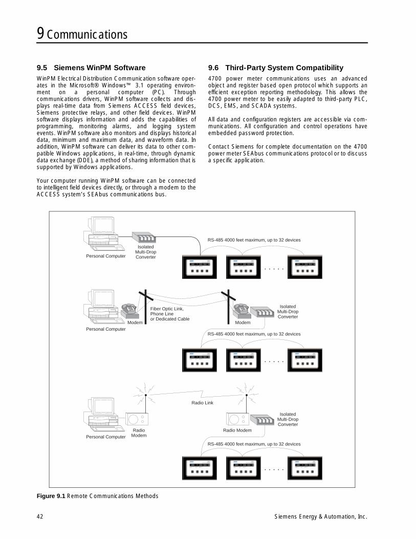
9 Communications
42 Siemens Energy & Automation, Inc.
9.5 Siemens WinPM SoftwareWinPM Electrical Distribution Communication software oper-ates in the Microsoft® Windows™ 3.1 operating environ-ment on a personal computer (PC). Throughcommunications drivers, WinPM software collects and dis-plays real-time data from Siemens ACCESS field devices,Siemens protective relays, and other field devices. WinPMsoftware displays information and adds the capabilities ofprogramming, monitoring alarms, and logging systemevents. WinPM software also monitors and displays historicaldata, minimum and maximum data, and waveform data. Inaddition, WinPM software can deliver its data to other com-patible Windows applications, in real-time, through dynamicdata exchange (DDE), a method of sharing information that issupported by Windows applications.
Your computer running WinPM software can be connectedto intelligent field devices directly, or through a modem to theACCESS system’s SEAbus communications bus.
9.6 Third-Party System Compatibility4700 power meter communications uses an advancedobject and register based open protocol which supports anefficient exception reporting methodology. This allows the4700 power meter to be easily adapted to third-party PLC,DCS, EMS, and SCADA systems.
All data and configuration registers are accessible via com-munications. All configuration and control operations haveembedded password protection.
Contact Siemens for complete documentation on the 4700power meter SEAbus communications protocol or to discussa specific application.
Figure 9.1 Remote Communications Methods
Personal Computer
Personal Computer
Personal Computer
IsolatedMulti-DropConverter
IsolatedMulti-DropConverter
IsolatedMulti-DropConverter
RS-485 4000 feet maximum, up to 32 devices
RS-485 4000 feet maximum, up to 32 devices
RS-485 4000 feet maximum, up to 32 devices
Modem Modem
Fiber Optic Link,Phone Lineor Dedicated Cable
RadioModem
Radio Modem
Radio Link
10 Maintenance
Siemens Energy & Automation, Inc. 43
10 MaintenanceThe following two circumstances describe the only regularmaintenance that the 4700 power meter may require.
10.1 Battery ReplacementThe 4700 power meter nonvolatile memory (NVRAM) circuitcontains an integrated battery backup system.
The rated life of the NVRAM battery is seventy years at122°F (50°C), 28 years at 140°F (60°C), and 11 years at158°F (70°C). If the unit operates at less than 122°F (50°C)for 60% of the time, less than 140°F (60°C) for 90% of thetime, and less than 158°F (70°C) for 100% of the time, theexpected life of the NVRAM battery is 35 years. If the meteris operating in an environment where the temperatures regu-larly exceed 140°F (60°C), the NVRAM battery should bereplaced every ten years.
Note: When the NVRAM is replaced, historic datamay be lost. We recommend backing upcritical logged data to the hard drive of acomputer prior to servicing. Setup parame-ters and calibration of the unit are notaffected.
10.2 CalibrationThe calibration interval for the 4700 power meter dependson your accuracy requirements. The rated accuracy drift is0.1% per year.
For information regarding the required calibration procedure,contact your local Siemens sales representative.
10.3 Field Service ConsiderationsIn the unlikely event that the 4700 power meter unit shouldfail, servicing requires disconnection and removal of the unitfrom its mounting for the purpose of repair, or for exchangewith a replacement unit. The initial installation should be donein a way which makes this as convenient as possible:
1. All power to the 4700 power meter should be removedand connections grounded.
2. Current transformer secondary leads should be short-circuited at the CT shorting block. Check to be sure thatprotective relaying is not affected.
3. All wiring should be routed to allow easy removal of theconnections to the 4700 power meter terminal strips,the 4700 power meter rear cover, and the 4700 powermeter itself.
11 Troubleshooting
44 Siemens Energy & Automation, Inc.
11 TroubleshootingA number of problems can cause the 4700 power meter notto function properly. This section lists possible problems andexplains how to correct them.
1. If the display does not operate:
a. check that there is an appropriate voltage availableto the power supply (L and N connections on theterminal strip).
b. confirm that the VREF terminal is connected directlyto ground.
c. press a button on the front panel.
2. If the voltage or current readings are incorrect:
a. Check that the VOLTS MODE is properly set for thegiven wiring.
b. Check that the voltage and current scales are prop-erly set.
c. Make sure the VREF terminal is properly grounded.
d. Check the quality of the CTs and VTs in use.
e. Make the following voltage tests:
• V1, V2, V3 to VREF are 120 VAC (or rated fullscale values of 277 or 347 VAC).
• VREF to switchgear earth ground is 0 V.• L to VREF is 120 VAC or DC (or optional rated
control power voltage).• N to VREF is less than 2 VAC.• All current inputs are less than 1 VAC with
respect to VREF.
3. If the kW or Power Factor readings are incorrect butvoltage and current readings are correct:
make sure that the phase relationship between voltageand current inputs is correct by comparing the wiringwith the appropriate wiring diagram.
4. If RS-232 or RS-485 communication does not work:
a. check that the BAUD RATE matches all otherACCESS devices on the network or the personalcomputer.
b. check that the communications mode (RS-232 orRS-485) set by the jumper on the communicationscard is correct for the type of standard being used(see Chapter 3, section 3.1).
c. check that the UNIT ID (address) of the 4700 powermeter matches the configuration of the Power Moni-tor unit or other computer.
If your problem persists after performing the specified steps,or if the problem is not listed above, contact Siemens.
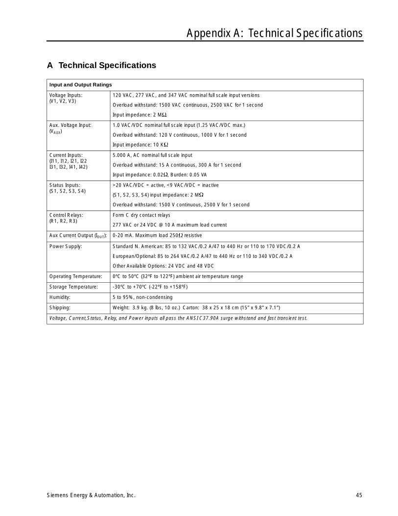
Appendix A: Technical Specifications
Siemens Energy & Automation, Inc. 45
A Technical Specifications
Input and Output Ratings
Voltage Inputs:(V1, V2, V3)
120 VAC, 277 VAC, and 347 VAC nominal full scale input versions
Overload withstand: 1500 VAC continuous, 2500 VAC for 1 second
Input impedance: 2 M
Aux. Voltage Input:(VAUX)
1.0 VAC/VDC nominal full scale input (1.25 VAC/VDC max.)
Overload withstand: 120 V continuous, 1000 V for 1 second
Input impedance: 10 K
Current Inputs:(I11, I12, I21, I22I31, I32, I41, I42)
5.000 A, AC nominal full scale input
Overload withstand: 15 A continuous, 300 A for 1 second
Input impedance: 0.02, Burden: 0.05 VA
Status Inputs:(S1, S2, S3, S4)
>20 VAC/VDC = active, <9 VAC/VDC = inactive
(S1, S2, S3, S4) input impedance: 2 M
Overload withstand: 1500 V continuous, 2500 V for 1 second
Control Relays:(R1, R2, R3)
Form C dry contact relays
277 VAC or 24 VDC @ 10 A maximum load current
Aux Current Output (IOUT): 0-20 mA. Maximum load 250 resistive
Power Supply: Standard N. American: 85 to 132 VAC/0.2 A/47 to 440 Hz or 110 to 170 VDC/0.2 A
European/Optional: 85 to 264 VAC/0.2 A/47 to 440 Hz or 110 to 340 VDC/0.2 A
Other Available Options: 24 VDC and 48 VDC
Operating Temperature: 0ºC to 50ºC (32ºF to 122ºF) ambient air temperature range
Storage Temperature: -30ºC to +70ºC (-22ºF to +158ºF)
Humidity: 5 to 95%, non-condensing
Shipping: Weight: 3.9 kg. (8 lbs, 10 oz.) Carton: 38 x 25 x 18 cm (15” x 9.8” x 7.1”)
Voltage, Current,Status, Relay, and Power inputs all pass the ANSI C37.90A surge withstand and fast transient test.
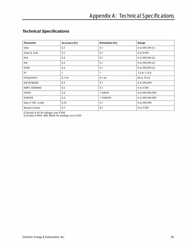
Appendix A: Technical Specifications
Siemens Energy & Automation, Inc. 46
Technical Specifications
Parameter Accuracy (%) Resolution (%) Range
Volts 0.2 0.1 0 to 999,999 (1)
Amps (L & N) 0.2 0.1 0 to 9,999
KVA 0.4 0.1 0 to 999,999 (2)
KW 0.4 0.1 0 to 999,999 (2)
KVAR 0.4 0.1 0 to 999,999 (2)
PF 1 1 1.0 to +/-0.6
FREQUENCY 0.2 Hz 0.1 Hz 40 to 70 Hz
KW DEMAND 0.4 0.1 0 to 999,999
AMPS DEMAND 0.2 0.1 0 to 9,999
KWHR 0.4 1 KWHR 0 to 999,999,999
KVARHR 0.4 1 KVARHR 0 to 999,999,999
Vaux (1 VAC scale) 0.25 0.1 0 to 999,999
Neutral Current 0.2 0.1 0 to 9,999
(1) Reads in kV for voltages over 9,999(2) Reads in MVA, MW, MVAR for readings over 9,999
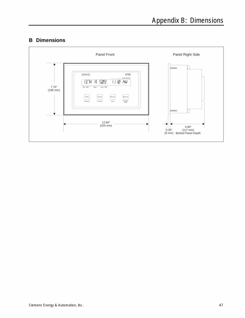
Appendix B: Dimensions
Siemens Energy & Automation, Inc. 47
B Dimensions
0.35"(9 mm)
4.60"(117 mm)
Behind Panel Depth
7.70"(196 mm)
12.60"(320 mm)
Panel Front Panel Right Side

Appendix C: Setpoint Parameter Form
Siemens Energy & Automation, Inc. 48
C Setpoint Parameter Form
Setpoint Type High Limit TD Operate Low Limit TD Release Relay/Function
1
2
3
4
5
6
7
8
9
10
11
12
13
14
15
16
17
Appendix D: Firmware Versions
Siemens Energy & Automation, Inc. 49
D Firmware VersionsThe following table lists each software version release for the4700 power meter and the new features or performanceenhancements added with each release.
The version number is identified on the label on the rearcover of the 4700 power meter (see Figure 1.1 in Chapter1). If yours is currently using a software version older thanthe most recent version listed in the table below, you canupgrade the software in that unit by contacting your localrepresentative or the manufacturer. Upgrades to the 4700power meter require a simple replacement of the EPROM(integrated circuit “chip”), which contains the operating soft-ware inside the unit. This replacement procedure must bedone by trained electronics service personnel.
Hardware Revision BFrom now on, all EPROMs are available for either the A or Bhardware. They are not interchangeable. Normally, only the Bis released except for an upgrade of an older meter. RevisionB meters are easily distinguished from revision A meters bythe following:
• Raised black plastic bezel (Rev. A has a flat, white metalbezel)
• Product Rev: B printed on back of meter
• VREP terminal (Rev. A does not have a VREF terminal)
Software version
Release Date Description
2.2.0.2B January 1, 1992 Exactly the same as Rev. A 2.2.0.2
2.2.0.3B March 31, 1992 Fixed bug that limited unit ID (address) to 1 thru 99
2.2.0.4B January, 1993 • Fixed bug with kWH/kVARHoverflow causing display to blink
• Fixed but that lost passwordchanges if powered down
• Adds waveform capture feature
• Adds reverse kVARH value;kVARH and kWH changed toreturn forward, not total values
• Adds configurable relay pulsing
• Add kW FWD, kVAR FWD, andkVAR REV setpoints
• PF display changed to LD/LG
• 3-wire WYE mode allows for2VT/3CT
• Demand period is now based ontime of day
• Added ,/. configuration of dis-play values (European format)
• RTS line is asserted 10 msecbefore TX in RS-232 mode
• PM 3.13 logs diagnostic code 1type 1 errors with this version
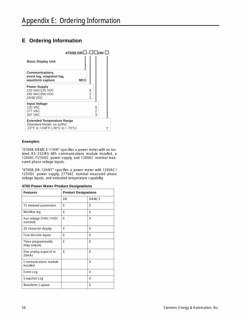
Appendix E: Ordering Information
50 Siemens Energy & Automation, Inc.
E Ordering Information
Examples:
“4700B-DRMC3-11HN” specifies a power meter with an iso-lated RS-232/RS-485 communications module installed, a120VAC/125VDC power supply, and 120VAC nominal mea-sured phase voltage inputs.
“4700B-DR-12HNT” specifies a power meter with 120VAC/125VDC power supply, 277VAC nominal measured phasevoltage inputs, and extended temperature capability.
4700 Power Meter Product Designations
Features Product Designations
DR DRMC3
15 metered parameters X X
Min/Max log X X
Aux voltage (1VAC/1VDC nominal)
X X
20 character display X X
Four discrete inputs X X
Three programmable relay outputs
X X
One analog ouput (4 to 20mA)
X X
Communications module installed
X
Event Log X
Snapshot Log X
Waveform Capture X
Communications,event log, snapshot log,waveform capture
Power Supply120 VAC/125 VDC240 VAC/250 VDC24/48 VDC
Input Voltage120 VAC277 VAC347 VAC
Extended Temperature Range(Standard Model, no suffix)-22°F to +158°F (-30°C to + 70°C)
4700B-DR – HN
MC3
123
T
123
Basic Display Unit
Index
Siemens Energy & Automation, Inc. I- i
A
AMPS SCALE parameter, 24, 28, 29auxiliary current output (IOut), 20
operation, 24auxiliary voltage input (VAux), 20
operation, 24
B
battery, 39replacing, 39
BAUD RATE parameter, 36baud rate, 36
C
calibration (of device), 39chassis ground, 3CLEAR KW/KVARHRS? parameter, 30CLEAR MAX/MIN? parameter, 30COM MODE parameter, 30communications card, 13communications, 36–37baud rate, 30
device address, 30parameters for, 30RS-232 to RS-485 converter, 36RTS ACTIVE LVL, 30troubleshooting problems, 40wiring, 13
connection,auxiliary current output, 20auxiliary voltage input, 20chassis ground, 3control relays, 18power supply, 3power wiring, 3RS-232 14RS-485, 15status inputs, 17VOLTS MODE parameter, 24VREF terminal, 3
control relays,connections for, 18operation of, 27–28pulse operation, 27
current transformers,and AMPS SCALE, 24requirements for, 5
Cursor button, 23Cursor,
function, 23
D
Decrement button, 23Decrement,
function, 23DEMAND PERIOD parameter, 30, 35demand, 35device specifications, 41–42DISPLAY TIMEOUT parameter, 30display,
changing numbers format, 27changing phase labels format, 27FORMAT parameter, 30labels used, 22modes available, 21reading the display, 21troubleshooting problems, 40
E
event log,control relay log entries, 28
F-H
FORMAT parameter, 27, 30fourth current input. See I4.Function button, 21, 22, 23
I-L
I OUT KEY parameter, 24, 30I OUT RANGE parameter, 30I OUT SCALE parameter, 30I4 (fourth current input), 5, 28I4 SCALE parameter, 30Increment button, 23Increment,
function, 23installation, 3–11
field service considerations, 39IOUT POWER FACTOR parameter, 24IOUT RANGE parameter, 24IOUT SCALE parameter, 24IOut. See auxiliary current output.
M
maintenance, 39Maximum button, 22min/max logs,
clearing, 30
Index
I-ii Siemens Energy & Automation, Inc.
Minimum button, 22, 23modem connection, 36modem,
connections, 36mounting the device, 3
dimensions for (illustration), 4
N
NUM DMD PERIODS parameter, 35
O
over setpoint, 31
P-Q
Parameter Select button, 23Parameter Select,
function, 23PASSWORD parameter, 23, 29peak demand, 35Phase button, 21power supply, 3programming,
entering programming mode, 23minimum requirements, 24using the front panel, 25–26using WinPM software, 37with WinPM, 37
protocol, 37
R
RELAY OPERATION parameter, 27, 29RS-232,
cable wiring for (illustration), 15communications, 36
See also communications.connections for (illustration), 14connections for, 14selecting this communications mode, 13
RS-232. See also communications.RS-485,
communications, 36See also communications.
connections for (illustration), 15connections for, 15selecting this communications mode, 13
RS-485. See also communications.RTS ACTIVE LVL parameter, 30, 36
S
SEAbus, 37SETPOINT NUM parameter, 24, 29, 32setpoints, 31–33
parameter form, 44setpoint relay operation, 27skipping setpoint parameters, 24
status inputs, 28connections for, 17
STNDRD FREQ parameter, 30
T
troubleshooting, 40
U
under setpoint, 32UNIT ID parameter, 30, 36UNIT ID, 36
V
VAUX SCALE parameter, 30VAUX. See auxiliary voltage input. 24VOLT SCALE parameter, 24, 29voltage transformers,
and VOLT SCALE, 24requirements for, 5
VOLTS MODE parameter, 24, 30VREF terminal, 3
W-Z
waveform data,connections for waveform capture, 5
WinPM software, 37wiring,
communications wiring, 13–16control relays, 18power wiring, 3status inputs, 17
wiring. See also installation.

Siemens Energy & Automation, Inc.
Warranty
Siemens Energy & Automation, Inc. warrants that all equipment purchased hereunder is warranted on a "RETURN TOFACTORY" basis against all defects in workmanship and materials under normal and proper use and service in its unmod-ified condition for a period of one (1) year from the date of initial shipment. Siemens Energy & Automation, Inc.'s sole obli-gation under this warranty shall be limited to furnishing parts and labor to remedy such defects; either, at the option ofSiemens Energy & Automation, Inc., by replacing or repairing any defective parts which are returned to Siemens Energy &Automation, Inc. factory or by making available at a Purchaser designated facility a repaired or replaced part. All replacedequipment shall become the property of Siemens Energy & Automation, Inc. The cost of freight to and from SiemensEnergy & Automation, Inc. Siemens Energy & Automation, Inc. will be borne by the Purchaser. If Siemens Energy & Auto-mation, Inc. determines that the equipment returned to it for warranty correction is not defective, as herein defined, Pur-chaser shall pay Siemens Energy & Automation, Inc., all costs of service, parts, handling and transportation.
Product Return ProcedureContact Siemens Energy & Automation Customer Service at 800-427-2256 for information on the product return proce-dure.

Siemens Energy & Automation, Inc.Power Distribution Solutions3333 Old Milton ParkwayAlpharetta, GA 30005
For Nearest Sales Office1.800.964.4114www.sea.siemens.comsales/salesoffices.html
For More Information Visitwww.sea.siemens.com/access
© Siemens Energy & Automation, Inc.Siemens is a registered trademark of Siemens AG. Specifications are subject to change without notice.
Windows is a trademark and Microsoft is a registered trademark of Microsoft Corporation.
Order No. XXOM-00102-1199PDF 1199 Printed in the U.S.A.