Embed Size (px)
Citation preview

Surgical Technique

CPCS™ Collarless Polished Cemented Stem
Nota Bene
The technique description herein is made available to the healthcare professional to illustrate theauthors’ suggested treatment for the uncomplicated procedure. In the final analysis, the preferredtreatment is that which addresses the needs of the patient.
Surgical technique completed in conjunction with
James B. Benjamin, MDClinical Associate Professor of SurgeryDepartment of Orthopaedic SurgeryUniversity of Arizona College of MedicineTucson, Arizona, USA
Knute Buehler, MDChief of Arthritis and Joint Replacement SurgeryOrthopaedic and Neurosurgery Center of the CascadesSt. Charles Medical CenterBend, Oregon, USA
Kevin L. Garvin, MDProfessor of Orthopaedic SurgeryUniversity of Nebraska Medical CenterOmaha, Nebraska, USA
James C. Kudrna, MD, PhDIllinois Bone and Joint Institute LTDChicago, Illinois, USA
Stephen McMahon, MB MS, FRACS, FA (Orth.)Consultant Orthopaedic Surgeon Monash Medical CentreMelbourne, Australia
Lars Weidenhielm, MD, PhDAssociate Professor and Senior ConsultantDepartment of OrthopaedicsKarolinska HospitalStockholm, Sweden
2

Stem Specifications
When Femoral Head Component Selected Is:
Size –3 +0 +4 +8 +12 +16
0 25 28 32 36 40 44
0H 29 32 36 40 44 48
1 27 30 34 38 42 46
1H 32 35 39 43 47 51
2 29 32 36 40 44 48
2H 35 38 41 45 49 53
3 31 34 38 42 46 50
3H 39 42 46 50 54 58
4 33 36 40 44 48 52
4H 41 44 48 52 56 60
5 35 38 42 46 50 54
5H 43 46 50 54 58 62
Neck Distal Cross Stem A-P M-LSize Angle Section Length Width Width0, 0H 131°/125° 4.5mm 120mm 11mm 26mm
1, 1H 131°/125° 4.5mm 135mm 12mm 26mm
2, 2H 131°/125° 4.5mm 135mm 13mm 28mm
3, 3H 131°/125° 4.5mm 135mm 15mm 30mm
4, 4H 131°/125° 4.5mm 135mm 16mm 32mm
5, 5H 131°/125° 4.5mm 135mm 17mm 34mm
Neck Length mmWhen Femoral Head Component Selected Is:
Size –3 +0 +4 +8 +12 +16
0 31 33 36 39 42 45
0H 35 37 40 44 47 50
1 32 35 38 41 44 47
1H 39 41 44 48 51 54
2 34 36 39 42 45 48
2H 42 44 47 51 54 57
3 35 38 41 44 47 50
3H 46 48 51 55 58 61
4 37 39 42 45 48 51
4H 46 49 52 56 59 62
5 38 41 44 47 50 53
5H 49 51 54 58 61 64
Neck Offset mm
When Femoral Head Component Selected Is:
Size –3 +0 +4 +8 +12 +16
0 23 25 27 30 33 35
0H 23 25 27 30 32 34
1 24 26 28 31 34 36
1H 24 26 28 31 33 35
2 26 28 30 33 36 38
2H 26 28 30 33 35 37
3 28 30 32 35 37 40
3H 28 30 32 35 37 39
4 30 32 34 37 39 42
4H 30 32 34 36 39 41
5 32 34 36 39 41 44
5H 32 34 36 39 41 43
Neck Height mm
For use with Smith & Nephew 12/14 femoral heads only.
Specifications
3
��
����������������
��
����������� ���
�
�
�
���������
���������������
�����������
��������
����������
����������
�����������������
����������������
����������
�������
���������
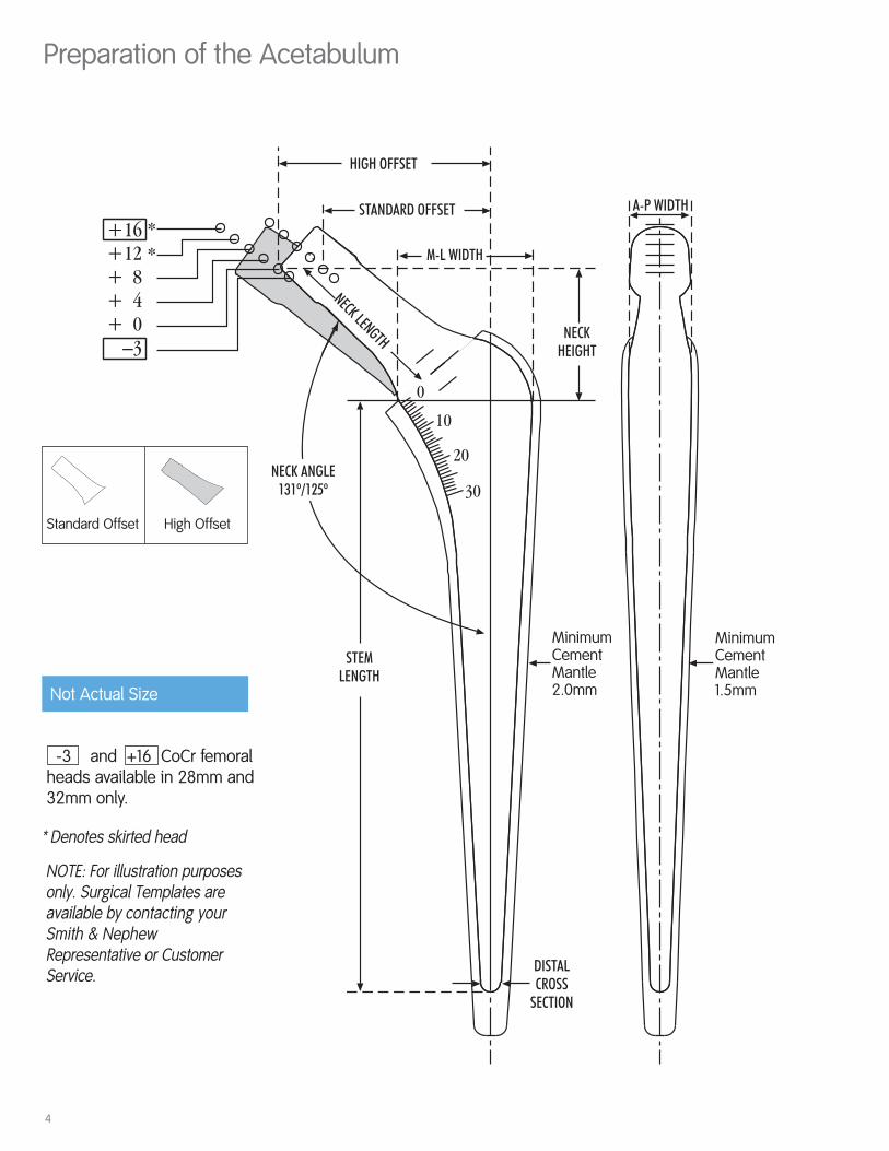
Preparation of the Acetabulum
NOTE: For illustration purposesonly. Surgical Templates areavailable by contacting yourSmith & NephewRepresentative or CustomerService.
-3 and +16 CoCr femoralheads available in 28mm and 32mm only.
Not Actual Size
* Denotes skirted head
High OffsetStandard Offset
MinimumCementMantle2.0mm
MinimumCementMantle1.5mm
4

Femoral Osteotomy
1. Femoral Osteotomy
The level of neck resection should be based onpreoperative templating. Place the template overthe X-ray of the hip. After determining theappropriate size stem, determine the level offemoral neck resection based on the lessertrochanter as a landmark.
A graduation scale can be found on the medialaspect of the stem on the template. This scalecorresponds to the marks on the osteotomy guide.Make note of how many graduations above thelesser trochanter the osteotomy will take place, asdetermined by the middle depth mark on themedial aspect of the stem (also identified as thezero mark on the graduation scale).
In the OR, place the osteotomy guide on the femurby referencing the lesser trochanter at the samegraduation mark as noted during templating.Osteotomize the neck (Figures 1 and 2).
2. Prepare Acetabulum
If acetabular reconstruction is required, prepare theacetabulum using the technique for the intendedacetabular component.
Figure 2
Figure 1
5

6
Femoral Canal Preparation
3. Femoral Canal Preparation
Open the medullary canal at the transected neckusing the box chisel. Stay posterior and lateral inorder to obtain a neutral stem position (Figure 3).Identify and open the femoral canal using the bluntmedullary reamer (Figure 4).
Figure 3
Figure 4
Figure 5
The trochanteric reamer isavailable to help ensure alateral start point and openthe metaphysis (Figure 5).

7
Femoral Canal Preparation
4. Femoral Broaching
Assemble the broach to the broach handle byplacing the broach post in the clamp. Use the thumbto lock the clamp onto the broach. A modularanteversion handle can be assembled to the broachhandle to provide version control (Figure 6).
Start the broaching procedure along the mid-axis ofthe femur with the starter broach and progressivelybroach to the appropriate femoral stem size. Seat thefinal broach slightly below the level of the femoralneck resection to facilitate calcar reaming if desired(Figure 7).
The CPCS broach is designed to provide a minimum2.0mm cement mantle per side, medially andlaterally, and 1.5mm per side, anteriorly andposteriorly. Additional cement mantle thickness isachieved by pressurizing the cement into thecancellous bone. The broach is 10mm longer thanthe corresponding implant to accommodate thedistal centralizer.
Disassemble the broach from the broach handle byplacing two fingers (index and middle) in therectangular slot. Apply pressure to the release bar bysqueezing two fingers toward the thumb resting onthe medial side of the broach handle (Figure 8).
Figure 6
Figure 7
Clamp
AnteversionHandle(optional)
Figure 8

8
Calcar Preparation & Trialing
6. Trialing
Remove the calcar reamer and place thematching standard or high offset trial neck (asdetermined by templating) onto the broach post.Select the trial femoral head of desired diameterand length. Reduce the hip to assess stabilityand to restore leg length. In some cases softtissue tension may be improved by using thehigh offset trial neck instead of the standardoffset trial neck.
The CPCS hip system was designed to allow thelast broach seated in the femur to dictate thesize implant to be used.
5. Calcar Preparation (optional)
If the femoral neck resection is asymmetric, withthe broach fully seated, remove the broachhandle and ream the calcar.Plane the calcar until it is level with the broach.
*Denotes skirted heads.
TrialColor 22mm 26mm 28mm 32mmGreen — — –3 –3Yellow +0 +0 +0 +0Red +4 +4 +4 +4White +8 +8 +8 +8Blue +12* +12* +12* +12*Black — — +16* +16*
Femoral Head And Neck Length Options

9
Sizing the Femoral Canal
7. Sizing the Femoral Canal
Attach the broach handle to the broach and removethe broach from the femoral canal.
Using femoral canal sounds, determine the canaldiameter to select the appropriately sized distalcentralizer and cement restictor (Figure 9).
A distal centralizer, ensures neutral stem alignment,and, if necessary, allows for slight subsidence of thestem by preventing the stem from becoming end-bearing in the cement. Neutral stem alignmentprovides a minimum 2.0mm cement mantle per side,medially and laterally, and 1.5mm cement mantle perside, anteriorly and posteriorly. Additional cementmantle thickness can be achieved by cement pressurization and the ensuingcement interdigitation.
Centralizers in 2mm increments are available in sizes8-18mm. Any size centralizer fits on any size stem.
Figure 9

10
Placing the BUCK™ Cement Restrictor
8. Placing the BUCK Cement Restrictor
The proximal flange of the cement restrictorshould always be larger than the distal canaldiameter. Accurate cement restrictor depthplacement is then determined by placing theCPCS stem (with attached centralizer) next to theinserter tool and adding 20mm to the length (seechart below).
Thread the cement restrictor onto the inserterusing a clockwise motion. Insert the device tothe level of the medullary canal that has beenpredetermined. Once this level is reached,disengage the restrictor from the inserter using acounterclockwise twisting motion. Remove theinserter from the medullary canal. If it isnecessary to remove the restrictor prior tocement insertion, it can be reattached to theinserter rod and pulled out of the canal. Thesurgeon may adjust the restrictor as many timesas required.
Size Depth0 140mm1 160mm2 160mm3 160mm4 160mm5 160mm
BUCK Plug Size Canal Size Catalog Number18.5mm <15mm 12941825mm 16-21mm 12941930mm 22-26mm 7127-942035mm 27-31mm 7127-9421

11
Preparing the Femoral Canal
9. Preparing The Femoral Canal
Irrigate the canal with saline solution and pulsatilelavage to remove all debris. Continue preparing thefemur with the femoral canal brush to remove anyremaining weak cancellous bone, blood clots, andmarrow fats. Repeat lavaging as necessary toremove all remaining debris.
10.Drying The Femoral Canal
Insert the canal suction absorber into the femoralcanal to dry the canal while mixing the cement.

12
Reconstruction Ring Surgical Technique
13. Injecting Cement
Remove the femoral canal suction absorber and usepulsatile lavage and dry. The cement should beintroduced promptly to minimize bleeding into thecanal. Insert the nozzle of the cement gun to the topof the Buck cement restrictor and inject cement intothe canal in retrograde fashion. Continue injectingcement until the canal is completely full and the distaltip of the nozzle is clear of the canal.
11. Loading Cement
Load VERSABOND™ bone cement into the VORTEX™ vacuum mixer.
12.Mixing
Mix the cement according to manufacturer’sinstructions. Turn handle clockwise to achieveoptimal homogenous mixture.

13
Pressurizing Cement
14.Pressurizing Cement
Break off the long nozzle and place the femoralpressurizer over the short nozzle. Apply thedisposable femoral pressurizer into the mouth of thecanal. This will occlude the canal and compress thecement. Maintain firm pressure until the cement isin a doughy state and can withstand displacementand will allow for proper cement interdigitation intotrabecular bone. Withdraw the femoral pressurizerand remove any extruded cement around theperiphery of the canal.

Stem Insertion
14
15. Stem Insertion
Using clean gloves, place the distal centralizer overthe distal tip of the stem by carefully pushing thecentralizer superiorly until snug.
Attach the CPCS stem driver handle to the stem driver. The handle can be attached in two positions, horizontal or vertical depending on surgeon preference (Figure 10). A button must tobe pushed at the end of the handle to eitherengage or disengage the handle.
Insert the selected femoral stem into the canal byfitting the tip of the locking stem driver into thestem driving platform (Figure 11). The circular discon the stem driver must be pulled superiorly toengage the tip of the stem driver to the stemdriving platform.
While pushing the stem into the canal, place the thumb medial to the stem in order to pressurizethe cement and ensure correct alignment (Figure12). Advance the stem approximately 1cm persecond to avoid air inclusions in the stem/cementinterface. The stem should be inserted to theappropriate medial depth mark as determinedduring trial reduction and templating.
Trim away excess cement with Concise cementsculps. Carefully remove the stem driver by pullingthe circular disc on the stem driver superiorly.Maintain steady pressure with the thumb on theneck taper until the cement is polymerized.
Figure 10
Figure 11
Figure 12

Final Trial Reduction
15
16.Final Trial Reduction
A final trial reduction may be performed at this timeusing trial femoral heads.
17. Femoral Head Assembly
Clean and dry the neck taper with a clean cloth.Place the prosthetic femoral head on the neck taperand firmly impact with a head impactor and a mallet.
NOTE: Care should be taken not to use Cobalt-Chromium heads on stainless steel stems. Todistinguish the material, the stainless steelfemoral heads have an indention at their taperopening, while the stainless steel stems havean indention in the middle of the taper.
Indentions to indicateStainless Steel

Catalog Information - Femoral Stem & Head Components
CPCS™ Primary Standard Offset StemsForged Cobalt Chromium – ASTM F 799
Stem Implant Broach/Trial Trial NeckSize Length Cat. No. Cat. No. Cat. No.
0 120mm 7131-2360 7136-3499 7136-27001 135mm 7131-2361 7136-3501 7136-27012 135mm 7131-2362 7136-3502 7136-27013 135mm 7131-2363 7136-3503 7136-27024 135mm 7131-2364 7136-3504 7136-27025 135mm 7131-2365 7136-3505 7136-2702
CPCS Primary High Offset StemsForged Cobalt Chromium – ASTM F 799
Stem Implant Broach/Trial Trial NeckSize Length Cat. No. Cat. No. Cat. No.
0 120mm 7131-2370 7136-3499 7136-27031H 135mm 7131-2371 7136-3501 7136-27042H 135mm 7131-2372 7136-3502 7136-27043H 135mm 7131-2373 7136-3503 7136-27054H 135mm 7131-2374 7136-3504 7136-27055H 135mm 7131-2375 7136-3505 7136-2705
CPCS Primary Standard Offset StemsStainless Steel – ASTM F 1586
Stem Implant Broach/Trial Trial NeckSize Length Cat. No. Cat. No. Cat. No.
0 120mm 7131-2380 7136-3499 7136-27001 135mm 7131-2381 7136-3501 7136-27012 135mm 7131-2382 7136-3502 7136-27013 135mm 7131-2383 7136-3503 7136-27024 135mm 7131-2384 7136-3504 7136-27025 135mm 7131-2385 7136-3505 7136-2702
CPCS Primary High Offset StemsStainless Steel – ASTM F 1586
Stem Implant Broach/Trial Trial NeckSize Length Cat. No. Cat. No. Cat. No.
0 120mm 7131-2390 7136-3499 7136-27031H 135mm 7131-2391 7136-3501 7136-27042H 135mm 7131-2392 7136-3502 7136-27043H 135mm 7131-2393 7136-3503 7136-27054H 135mm 7131-2394 7136-3504 7136-27055H 135mm 7131-2395 7136-3505 7136-2705
16

Catalog Information - Femoral Stem & Head Components
CPCS Distal CentralizersCat. No. OD
7131-2400 0mm7131-2408 8mm7131-2410 1mm7131-2412 12mm7131-2414 14mm7131-2416 16mm7131-2418 18mm
CoCr 12/14 Femoral HeadsCobalt Chromium – ASTM F 799
NeckLength 22mm 26mm
-3 — —+0 7130-2200 7130-2600+4 7130-2204 7130-2604+8 7130-2208 7130-2608+12 7130-2212 7130-2612+16 — —
NeckLength 28mm 32mm
-3 7130-2803 7130-3203+0 7130-2800 7130-3200+4 7130-2804 7130-3204+8 7130-2808 7130-3208+12 7130-2812 7130-3212+16 7130-2816 7130-3216
SST 12/14 Femoral HeadsStainless Steel – ASTM F 1586NeckLength 22mm 26mm
-3 — —+0 7129-2200 7129-2600+4 7129-2204 7129-2604+8 7129-2208 7129-2608+12 7129-2212 7129-2612+16 — —
NeckLength 28mm 32mm
-3 7129-2803 7129-3203+0 7129-2800 7129-3200+4 7129-2804 7129-3204+8 7129-2808 7129-3208+12 7129-2812 7129-3212+16 7129-2816 7129-3216
17

Catalog Information - Instrumentation
Femoral Head ImpactorCat. No. 7136-4009
Trial 12/14 Taper Femoral HeadsNeck ColorLength Code 22mm *26mm *28mm 32mm
— — 7135-2803 7135-32037135-2200 7135-2600 7135-2800 7135-32007135-2204 7135-2604 7135-2804 7135-32047135-2208 7135-2608 7135-2808 7135-32087135-2212 7135-2612 7135-2812 7135-3212— — 7135-2816 7135-3216
GreenYellowRedWhiteBlueBlack
–3+0+4+8 +12+16
CPCS™ Trial NecksPrimary PrimaryStandard Offset High Offset
Size Cat. No. Size Cat. No.
0 7136-2700 0H 7136-27031,2 7136-2701 1H,2H 7136-27043,4,5 7136-2702 3H,4H,5H 7136-2705
*Space allowed for 26 mm and 28 mm heads in instrument tray.
Anteversion HandleCat. No. 7136-4012
Osteotomy GuideCat. No. Size
7136-4000 Sizes 0–5
Box ChiselCat. No. Size
7136-4002 Small
Blunt Medullary ReamerCat. No. 11-9657
Trochanteric ReamerCat. No. 7136-4015
Broach HandleCat. No. 7136-4007
18

Calcar ReamersCat. No. Size
7136-4004 Small7136-4005 Large
CPCS Femoral Stem DriverCat. No. 7136-2631
CPCS™ Inserter HandleCat. No. 7136-2630
Femoral SoundsCat. No. Size
7136-3508 8-9mm7136-3510 10-11mm7136-3512 12-13mm7136-3514 14-15mm7136-3516 16-17mm7136-3518 18-19mm
CPCS Primary Instrument TrayCat. No. 7136-3528
Small Exterior Carrying CaseNot ShownCat. No. 7112-9401
Lid for Exterior Carrying CaseNot ShownCat. No. 7112-9402
Femoral Sound TrayNot ShownCat. No. 7136-3529
Broaches/TrialsCat. No. Size
7136-3499 Starter7136-3500 Size 07136-3501 Size 17136-3502 Size 27136-3503 Size 37136-3504 Size 47136-3505 Size 5
Catalog Information - Instrumentation
19

Catalog Information - Cement & Accessories
BUCK Cement RestrictorCat. No. Size
12-9418 18.5mm12-9419 25mm7127-9420 30mm7127-9421 35mm
Vent Opening ToolCat. No. 11-0028
PREP-IM™ KitCat. No. 12-1000
Kit contains the following:
Cat. No. Description
12-9418 BUCK™ Cement Restrictor, 18.5mm12-9419 BUCK Cement Restrictor, 25mm11-0003 Femoral Canal Brush, 19mm11-1000 Concise Cement Sculps Kit11-0037 Femoral Canal Suction Absorber, 19mm
— Disposable Cement Restrictor Tool(Available in kit only)
Concise Cement Sculps KitCat. No. 11-1000(one of each)
Femoral Canal Suction AbsorberCat. No. Size
11-0037 19mm11-0038 25mm
20

BUCK Femoral CementRestrictor Inserter Cat. No. 11-2428
Femoral PressurizersCat. No. Size
7127-0026 Small7127-0027 Medium7127-0028 Large
Femoral Canal BrushCat. No. OD
11-0003 19mm11-0033 12.5mm
MIXOR™ Vacuum Mixing System with SyringeCat. No. 7127-0020
Femoral Cement CompressorCat. No. 11-1434
Catalog Information - Cement & Accessories
21
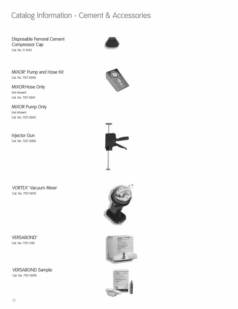
Catalog Information - Cement & Accessories
Disposable Femoral CementCompressor CapCat. No. 11-1435
Injector Gun Cat. No. 7127-2000
MIXOR™ Pump and Hose KitCat. No. 7127-0040
MIXOR Hose Only(not shown)
Cat. No. 7127-0041
MIXOR Pump Only(not shown)
Cat. No. 7127-0042
VERSABOND™Cat. No. 7127-1140
VORTEX™ Vacuum MixerCat. No. 7127-0070
VERSABOND SampleCat. No. 7127-0094
22

Catalog Information - Cement & Accessories
Connector, SchraederCat. No. 7127-0050
Connector, DragerCat. No. 7127-0051
Connector, DISSCat. No. 7127-0052
Handpiece with Zimmer CouplingCat. No. 7127-7000
Powerhose with Zimmer CouplingCat. No. 7127-7001
Hip and Knee without suctionCat. No. 7127-7004
Hip and Knee without SuctionCat. No. 7127-7005
21

Orthopaedic ReconstructionSmith & Nephew, Inc.1450 Brooks RoadMemphis, TN 38116USA
Telephone: 1-901-396-2121Information: 1-800-821-5700Orders/Inquiries: 1-800-238-7538
45720101-1 7138-0787 5/07
www.smith-nephew.com
™Trademark of Smith & Nephew. Certain marks Reg. US Pat & TM Off.