Embed Size (px)
Citation preview
25
RESEARCH PAPERS FACULTY OF MATERIALS SCIENCE AND TECHNOLOGY IN TRNAVA
SLOVAK UNIVERSITY OF TECHNOLOGY IN BRATISLAVA
2011 Number 30
METROLOGICAL CONTROL OF SELECTED SURFACE TYPES OF A MECHANICAL PART BY USING ON-MACHINE
MEASUREMENT SYSTEM
Michal OMÁMIK, Ivan BARÁNEK
Abstract
The paper is focused on the research of On-machine measurement systems for a CNC multi-axis milling machine. Research is aimed at the suitable selection of measuring parameters for On-machine measurement systems in order to reach an accurate and reliable quality control of the mechanical part. Theoretical information and overall concept of research are also presented.
Key words
on-machine measurement systems, coordinate measuring machine, accuracy, touch probe
Introduction
Quality control is one of the important parts of production process which can be performed trough many possible ways with different measuring gauges and equipment. New products following the trends of designers or requirements of industrial applications with freeform surfaces require instruments with high ability of measuring tasks solving. Regarding many advantages of On-machine measurement system, the utilization of the systems has become a subject of many researches. These systems allow controlling the parts directly on the machine tool, and also the process can be integrated directly to the machining process whereas the delays from transportation and measuring process performed on coordinated machine are omitted.
Michal Omámik, MSc. Eng., Ivan Baránek, Professor, Ph.D. – Institute of Production Technologies, Faculty of Materials Science and Technology, Slovak University of Technology Bratislava, Paulínska 16, 917 24 Trnava, Slovak Republic, e – mail: [email protected], [email protected]
26
Research concept of On-machine measurement system
Latest trends of metrological control of mechanical parts containing also freeform surfaces have brought requirements of the research in the field of On-machine measurement systems. Generally, the accuracy of measurements and authenticity of the results from the measurement is in most cases affected by many factors and this is truth also for the measurement by using CMM (Coordinate measuring machine) as well as in On-machine measurement systems. This fact brings questions related to the research needs of suitable selection of measuring parameters for On-machine measurement systems in order to reach an accurate and reliable quality control of a mechanical part produced on multi-axis milling machines. The factors affecting the accuracy, efficiency and uncertainty of measurement performed via On-machine measurement systems are the object of the research. Influence of partial factors and their interaction are going to be studied in the planned experiments. Partial stages of experiments will be carried out in order to observe the increasing complexity of the measuring task on the machine tool.
Aims and stages of experiments
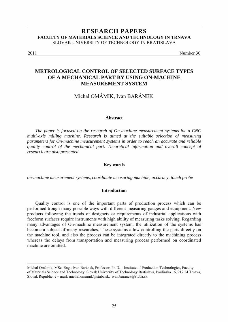
Partial stages of experiments (Fig. 1) are planned in order to observe the increasing
complexity of the measuring task depending on the complexity of the measured part. Based on this, there are the possibilities of On-machine measurement systems shown and compared to CMM.
Partial experiments can be divided into four stages:
Accuracy demonstration of On-machine measurement systems compared to CMM depending on suitable selection of measuring parameters
1. or surfaces from Primitive analysed on “artefact” for accuracy of dimension as well as for the derivate deviation, e. g. roundness, etc.,
2. for surfaces from Primitive analysed (the accuracy of dimensions as well as the derivate deviation, e. g. roundness, etc.) on part machined on the same machine tool from which On- machine measurement system is developed.
3. for features commonly machined and measured by the machine tool cycles (machined and measured at the same milling centre from which On - machine measurement system is developed)
4. for selected types of parts (with the different complexity designed for 3D, 4D and 5D milling) machined and measured on the same CNC milling machine.
In foreign literature, a term “artefact” is used as an etalon part with known and high accuracy, or as a test work piece for the machine tool evaluation or CMM (Coordinate measuring machine).
27
Fig. 1 Partial stages of the research of On-machine measurements system compared to CMM
(Coordinate measuring machine)
Parameters of experiments
Parameters of measurement and their interaction which could by set or selected will be the objects of experiments within the research of a suitable selection of measuring parameters for On-machine measurement system. This will bring complex information about On-machine measurement systems.
Following parameters are the objects of experiments: ● number of measuring points, ● distribution of measuring points based on different patterns of distribution as well as
based on patterns of measuring points distribution depending on the curvature of surface (stable, unstable and number of curvatures),
● Position and orientation within a range of part fixing on the machine tool table, ● Tilt angle of machine tool spindle (constrain from angle of measured part), ● Styli length, ● Speed of measuring.
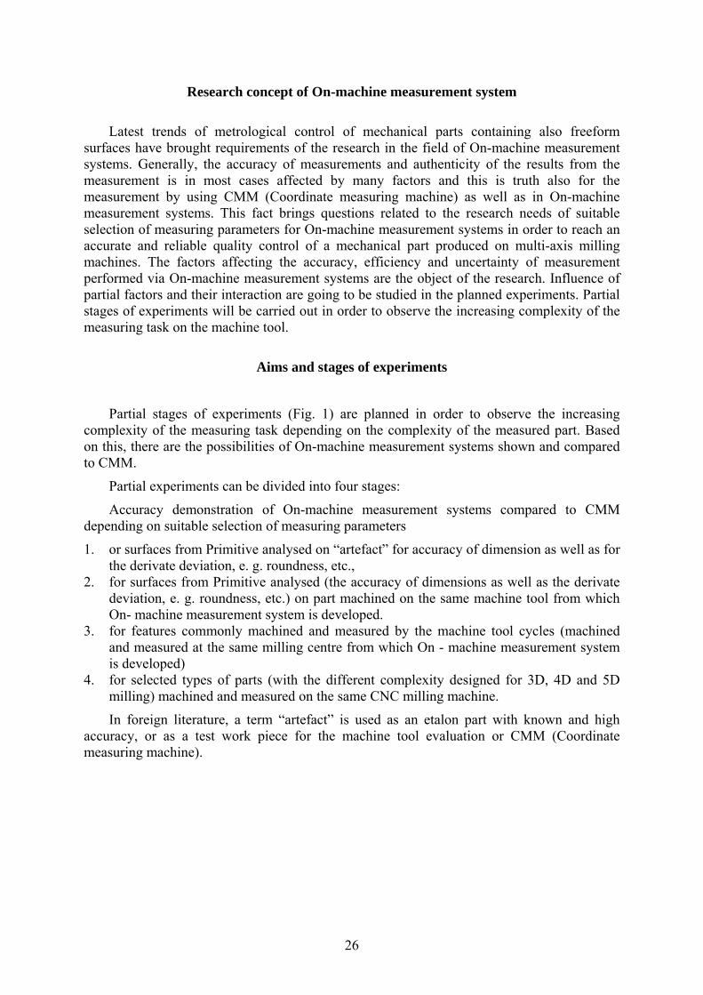
A detailed view of experiment parameters using the “artefact” parts in research of On-machine measurement system compared to CMM is illustrated in Fig. 2. In the same way, it is also possible to present details for other stages of experiments, e. g. for primitive surfaces
28
machined and measured on the same milling centre on which On-machine measurement system is developed, etc.
Fig. 2 A detailed view of parameters of experiments with using “artefact” parts in research of On-machine measurement system compared to CMM (Coordinate measuring machine)
Influence of partial factors of experiments
Since the result of measurement process depends on many factors, it is necessary to find
their partial importance. As mentioned above, the interaction between partial factors also plays an important role. The influence of partial major factors within the research of a suitable selection of measuring parameters for On-machine measurement system can be described as follows:
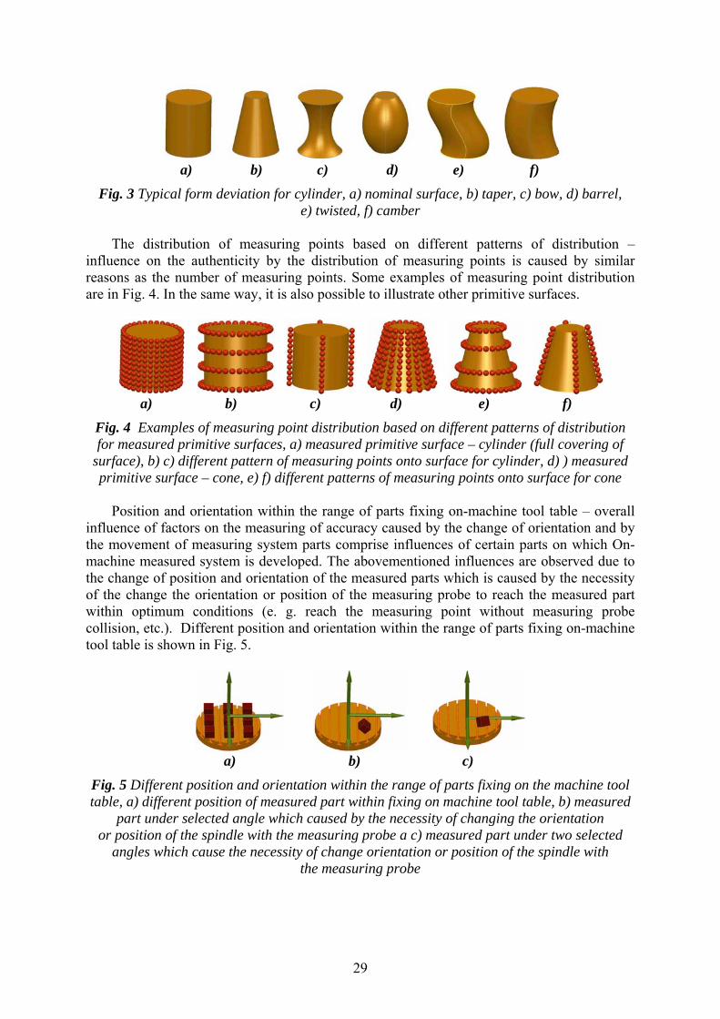
Number of measuring points – Number of measuring points has been the research subject of many authors focused on CMM measurement. It is necessary, however, to observe the interaction and impact of numbers of measuring points on the authenticity of measurement result together with other parameters. The importance of measuring point number is the result of the shape and dimension variability of the machined part (example for cylinder - Fig. 3), which can be caused by many factors as well (e. g. tool deflection, etc.). Accuracy of measured dimensions and derivate deviation, e. g. roundness, etc., is due to this fact directly influenced by the measuring point number. Moreover, the substitute element determined is also influenced by itself.
29
a) b) c) d) e) f)
Fig. 3 Typical form deviation for cylinder, a) nominal surface, b) taper, c) bow, d) barrel, e) twisted, f) camber
The distribution of measuring points based on different patterns of distribution –
influence on the authenticity by the distribution of measuring points is caused by similar reasons as the number of measuring points. Some examples of measuring point distribution are in Fig. 4. In the same way, it is also possible to illustrate other primitive surfaces.
a) b) c) d) e) f)
Fig. 4 Examples of measuring point distribution based on different patterns of distribution for measured primitive surfaces, a) measured primitive surface – cylinder (full covering of
surface), b) c) different pattern of measuring points onto surface for cylinder, d) ) measured primitive surface – cone, e) f) different patterns of measuring points onto surface for cone
Position and orientation within the range of parts fixing on-machine tool table – overall
influence of factors on the measuring of accuracy caused by the change of orientation and by the movement of measuring system parts comprise influences of certain parts on which On-machine measured system is developed. The abovementioned influences are observed due to the change of position and orientation of the measured parts which is caused by the necessity of the change the orientation or position of the measuring probe to reach the measured part within optimum conditions (e. g. reach the measuring point without measuring probe collision, etc.). Different position and orientation within the range of parts fixing on-machine tool table is shown in Fig. 5.
a) b) c)
Fig. 5 Different position and orientation within the range of parts fixing on the machine tool table, a) different position of measured part within fixing on machine tool table, b) measured
part under selected angle which caused by the necessity of changing the orientation or position of the spindle with the measuring probe a c) measured part under two selected
angles which cause the necessity of change orientation or position of the spindle with the measuring probe
30
Instruments for research implementation
To carry out the experimental part of research, a brand new CNC milling centres which
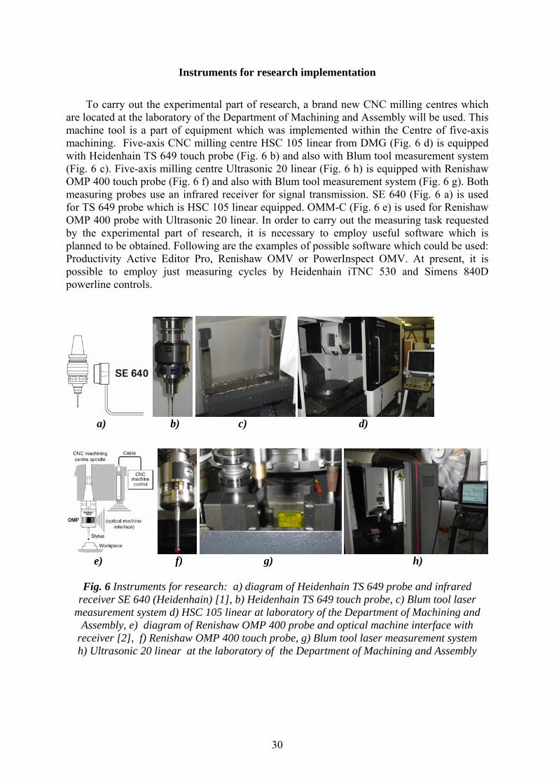
are located at the laboratory of the Department of Machining and Assembly will be used. This machine tool is a part of equipment which was implemented within the Centre of five-axis machining. Five-axis CNC milling centre HSC 105 linear from DMG (Fig. 6 d) is equipped with Heidenhain TS 649 touch probe (Fig. 6 b) and also with Blum tool measurement system (Fig. 6 c). Five-axis milling centre Ultrasonic 20 linear (Fig. 6 h) is equipped with Renishaw OMP 400 touch probe (Fig. 6 f) and also with Blum tool measurement system (Fig. 6 g). Both measuring probes use an infrared receiver for signal transmission. SE 640 (Fig. 6 a) is used for TS 649 probe which is HSC 105 linear equipped. OMM-C (Fig. 6 e) is used for Renishaw OMP 400 probe with Ultrasonic 20 linear. In order to carry out the measuring task requested by the experimental part of research, it is necessary to employ useful software which is planned to be obtained. Following are the examples of possible software which could be used: Productivity Active Editor Pro, Renishaw OMV or PowerInspect OMV. At present, it is possible to employ just measuring cycles by Heidenhain iTNC 530 and Simens 840D powerline controls.
a) b) c) d)
e) f) g) h)
Fig. 6 Instruments for research: a) diagram of Heidenhain TS 649 probe and infrared
receiver SE 640 (Heidenhain) [1], b) Heidenhain TS 649 touch probe, c) Blum tool laser measurement system d) HSC 105 linear at laboratory of the Department of Machining and
Assembly, e) diagram of Renishaw OMP 400 probe and optical machine interface with receiver [2], f) Renishaw OMP 400 touch probe, g) Blum tool laser measurement system h) Ultrasonic 20 linear at the laboratory of the Department of Machining and Assembly
31
Anticipated research results
Future research and experiments will be divided into few stages bringing complex information about On-machine measurement systems compared to CMM.
Following research and experiment results are expected: • dependence of accuracy for On-machine measurement systems comparing with
coordinate measuring machine, • dependence of partial parameters of measurement in order to reach required accuracy and
uncertainty of measurement, • interaction between partial factors within research of partial factors and their impact on
the accuracy and uncertainty of measurement, • information about the possibilities of parameters optimization in order to reach required
accuracy of measurement, • information about the levels of measurement inaccuracy performed by using On-machine
measurement systems compared to the measurement via the coordinate measuring machine (this will show deficiencies of the whole system developed by the machine tool and probe).
Completed Research Phase
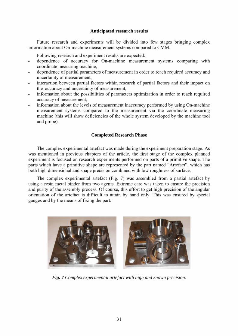
The complex experimental artefact was made during the experiment preparation stage. As was mentioned in previous chapters of the article, the first stage of the complex planned experiment is focused on research experiments performed on parts of a primitive shape. The parts which have a primitive shape are represented by the part named “Artefact”, which has both high dimensional and shape precision combined with low roughness of surface.
The complex experimental artefact (Fig. 7) was assembled from a partial artefact by using a resin metal binder from two agents. Extreme care was taken to ensure the precision and purity of the assembly process. Of course, this effort to get high precision of the angular orientation of the artefact is difficult to attain by hand only. This was ensured by special gauges and by the means of fixing the part.
Fig. 7 Complex experimental artefact with high and known precision.
32
Artefact calibration
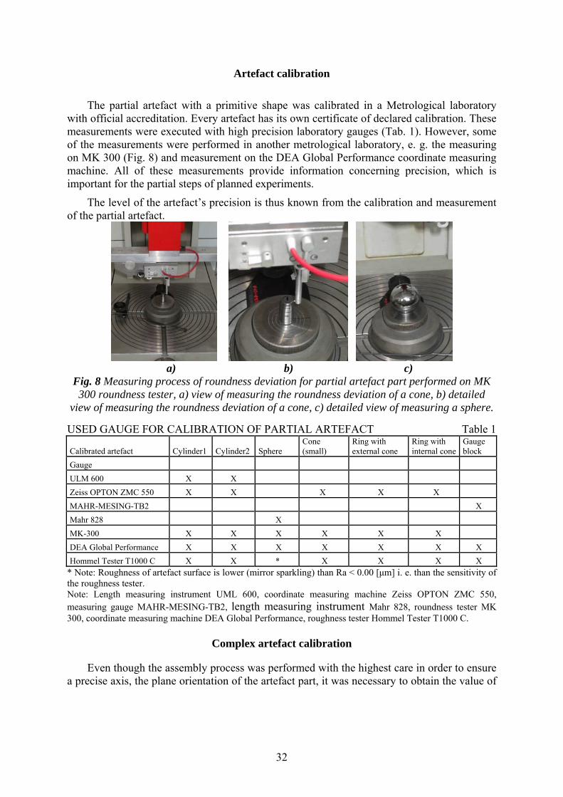
The partial artefact with a primitive shape was calibrated in a Metrological laboratory with official accreditation. Every artefact has its own certificate of declared calibration. These measurements were executed with high precision laboratory gauges (Tab. 1). However, some of the measurements were performed in another metrological laboratory, e. g. the measuring on MK 300 (Fig. 8) and measurement on the DEA Global Performance coordinate measuring machine. All of these measurements provide information concerning precision, which is important for the partial steps of planned experiments.
The level of the artefact’s precision is thus known from the calibration and measurement of the partial artefact.
a) b) c)
Fig. 8 Measuring process of roundness deviation for partial artefact part performed on MK 300 roundness tester, a) view of measuring the roundness deviation of a cone, b) detailed
view of measuring the roundness deviation of a cone, c) detailed view of measuring a sphere. USED GAUGE FOR CALIBRATION OF PARTIAL ARTEFACT Table 1
Calibrated artefact Cylinder1 Cylinder2 Sphere Cone (small)
Ring with external cone
Ring with internal cone
Gauge block
Gauge ULM 600 X X Zeiss OPTON ZMC 550 X X X X X MAHR-MESING-TB2 X Mahr 828 X MK-300 X X X X X X DEA Global Performance X X X X X X X Hommel Tester T1000 C X X * X X X X
* Note: Roughness of artefact surface is lower (mirror sparkling) than Ra < 0.00 [μm] i. e. than the sensitivity of the roughness tester. Note: Length measuring instrument UML 600, coordinate measuring machine Zeiss OPTON ZMC 550, measuring gauge MAHR-MESING-TB2, length measuring instrument Mahr 828, roundness tester MK 300, coordinate measuring machine DEA Global Performance, roughness tester Hommel Tester T1000 C.
Complex artefact calibration
Even though the assembly process was performed with the highest care in order to ensure a precise axis, the plane orientation of the artefact part, it was necessary to obtain the value of
33
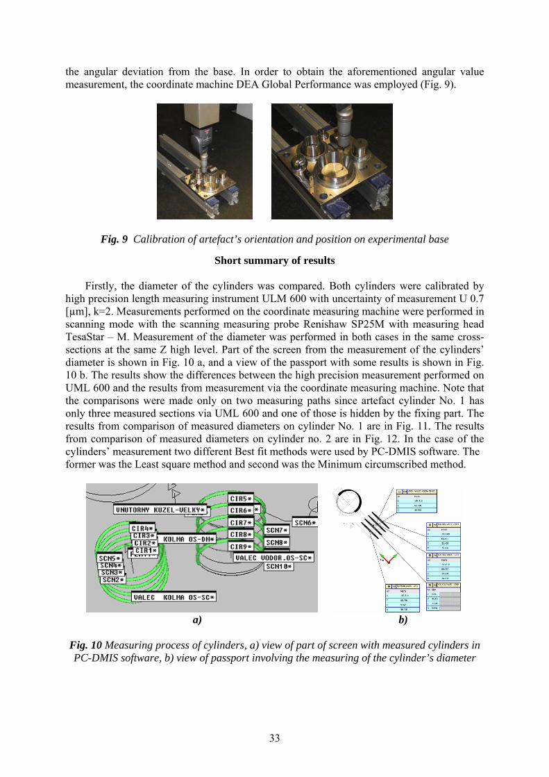
the angular deviation from the base. In order to obtain the aforementioned angular value measurement, the coordinate machine DEA Global Performance was employed (Fig. 9).
Fig. 9 Calibration of artefact’s orientation and position on experimental base
Short summary of results
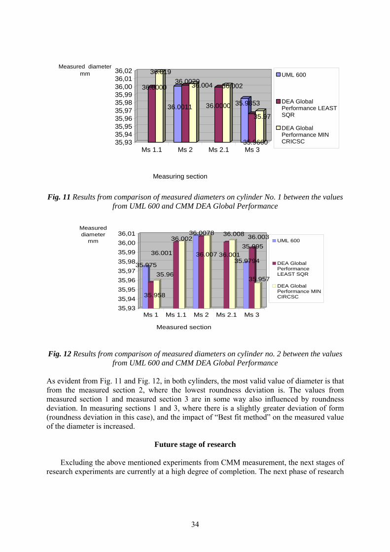
Firstly, the diameter of the cylinders was compared. Both cylinders were calibrated by high precision length measuring instrument ULM 600 with uncertainty of measurement U 0.7 [µm], k=2. Measurements performed on the coordinate measuring machine were performed in scanning mode with the scanning measuring probe Renishaw SP25M with measuring head TesaStar – M. Measurement of the diameter was performed in both cases in the same cross-sections at the same Z high level. Part of the screen from the measurement of the cylinders’ diameter is shown in Fig. 10 a, and a view of the passport with some results is shown in Fig. 10 b. The results show the differences between the high precision measurement performed on UML 600 and the results from measurement via the coordinate measuring machine. Note that the comparisons were made only on two measuring paths since artefact cylinder No. 1 has only three measured sections via UML 600 and one of those is hidden by the fixing part. The results from comparison of measured diameters on cylinder No. 1 are in Fig. 11. The results from comparison of measured diameters on cylinder no. 2 are in Fig. 12. In the case of the cylinders’ measurement two different Best fit methods were used by PC-DMIS software. The former was the Least square method and second was the Minimum circumscribed method.
a) b)
Fig. 10 Measuring process of cylinders, a) view of part of screen with measured cylinders in PC-DMIS software, b) view of passport involving the measuring of the cylinder’s diameter
34
36.0000
36.019
36.0011
36.002036.004
36.0000
36.002
35.9853
35.9660
35.97
35,9335,9435,9535,9635,9735,9835,9936,0036,0136,02
Measured diameter mm
Ms 1.1 Ms 2 Ms 2.1 Ms 3
Measuring section
UML 600
DEA GlobalPerformance LEASTSQR
DEA GlobalPerformance MINCRICSC
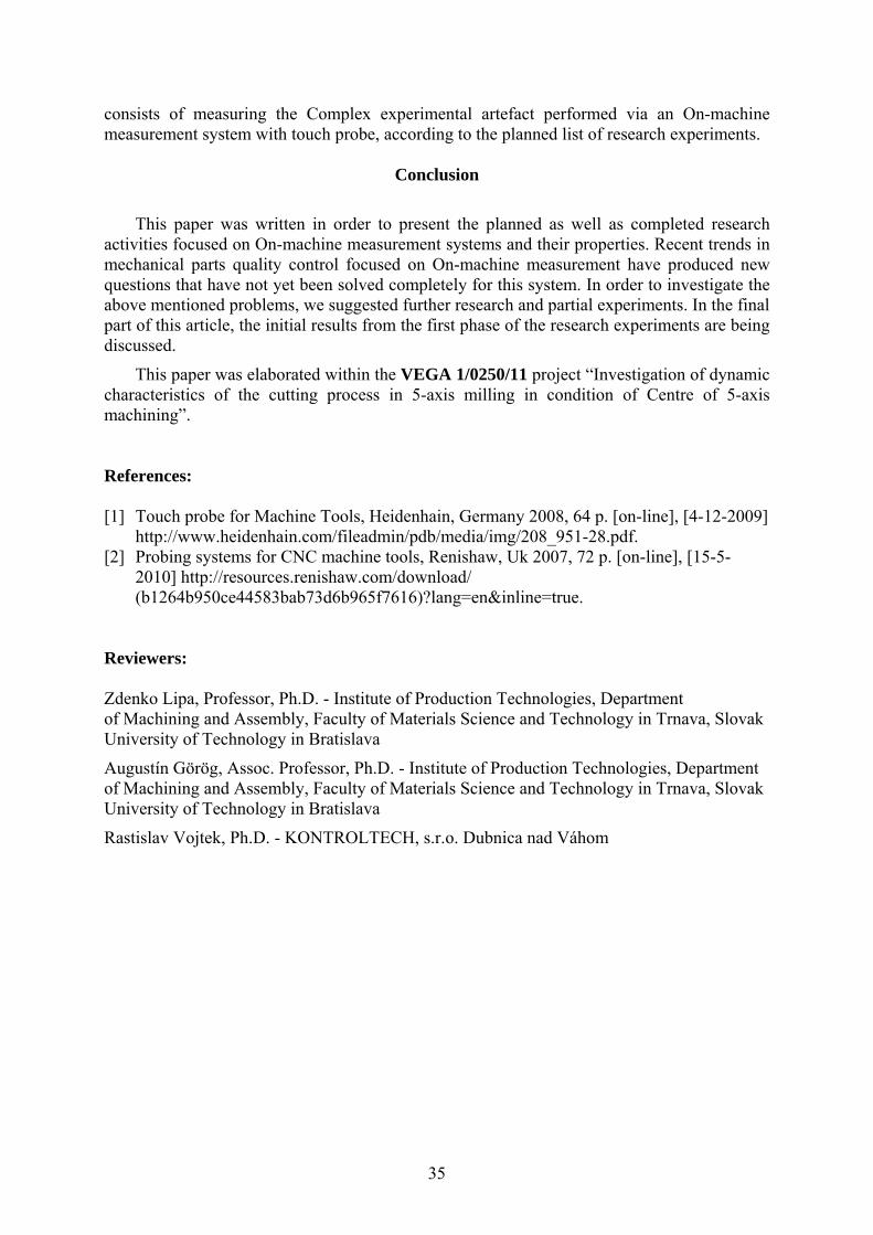
Fig. 11 Results from comparison of measured diameters on cylinder No. 1 between the values from UML 600 and CMM DEA Global Performance
35.975
35.958
35.96
36.001
36.00236.0078
36.007
36.008
36.001
36.003
35.9794
35.995
35.957
35,9335,9435,9535,9635,9735,9835,9936,0036,01
Measured diameter
mm
Ms 1 Ms 1.1 Ms 2 Ms 2.1 Ms 3
Measured section
UML 600
DEA GlobalPerformanceLEAST SQR
DEA GlobalPerformance MINCIRCSC
Fig. 12 Results from comparison of measured diameters on cylinder no. 2 between the values
from UML 600 and CMM DEA Global Performance
As evident from Fig. 11 and Fig. 12, in both cylinders, the most valid value of diameter is that from the measured section 2, where the lowest roundness deviation is. The values from measured section 1 and measured section 3 are in some way also influenced by roundness deviation. In measuring sections 1 and 3, where there is a slightly greater deviation of form (roundness deviation in this case), and the impact of “Best fit method” on the measured value of the diameter is increased.
Future stage of research
Excluding the above mentioned experiments from CMM measurement, the next stages of research experiments are currently at a high degree of completion. The next phase of research
35
consists of measuring the Complex experimental artefact performed via an On-machine measurement system with touch probe, according to the planned list of research experiments.
Conclusion
This paper was written in order to present the planned as well as completed research activities focused on On-machine measurement systems and their properties. Recent trends in mechanical parts quality control focused on On-machine measurement have produced new questions that have not yet been solved completely for this system. In order to investigate the above mentioned problems, we suggested further research and partial experiments. In the final part of this article, the initial results from the first phase of the research experiments are being discussed.
This paper was elaborated within the VEGA 1/0250/11 project “Investigation of dynamic characteristics of the cutting process in 5-axis milling in condition of Centre of 5-axis machining”. References: [1] Touch probe for Machine Tools, Heidenhain, Germany 2008, 64 p. [on-line], [4-12-2009]
http://www.heidenhain.com/fileadmin/pdb/media/img/208_951-28.pdf. [2] Probing systems for CNC machine tools, Renishaw, Uk 2007, 72 p. [on-line], [15-5-
2010] http://resources.renishaw.com/download/ (b1264b950ce44583bab73d6b965f7616)?lang=en&inline=true.
Reviewers: Zdenko Lipa, Professor, Ph.D. - Institute of Production Technologies, Department of Machining and Assembly, Faculty of Materials Science and Technology in Trnava, Slovak University of Technology in Bratislava
Augustín Görög, Assoc. Professor, Ph.D. - Institute of Production Technologies, Department of Machining and Assembly, Faculty of Materials Science and Technology in Trnava, Slovak University of Technology in Bratislava
Rastislav Vojtek, Ph.D. - KONTROLTECH, s.r.o. Dubnica nad Váhom

36


![PROG1 - UIMPROG1 Prednášajúci: Tomáš Fabšič, tomas.fabsic[at]stuba.sk (dnes zastupuje Viliam Hromada) Cvičiaci: Viliam Hromada, viliam.hromada[at]stuba.sk Tomáš Fabšič](https://img.pdfslide.us/doc/110x75/603e7160ccd67d59c2589a8e/prog1-uim-prog1-prednajci-tom-fabi-tomasfabsicatstubask-dnes.jpg)