Embed Size (px)
Citation preview
2012 SLOVAK UNIVERSITY OF TECHNOLOGY28
J. ŠIMIČEK, O. HUBOVÁ
NUMERICAL ANALYSIS OF THE EFFECTS OF WIND ON BUILDING STRUCTURES
KEY WORDS
• Laminarandturbulentflow,• Newtonianfluid,• Finiteelementmethod,• Numericalsimulationofflows,• Streamlines,• Windspeed,• Windpressurecoefficient.
ABSTRACT
The paper deals with the theoretical foundations of laminar and turbulent fluid flows in a boundary layer and the effects of wind on constructions. The application section describes the flow of compressible Newtonian fluid as a system of partial differential equations (the Navier-Stokes equation) and solves these equations using FEM at each time step. Simplifying a 3D task to a plane problem and ignoring vorticity allows for the formulation of a wind flow on an open terrain and the effects of wind on a barrier. Two approaches to the numerical solution of wind flows are presented: one involves the Fluent commercial program to obtain the velocity field and pressure at a constant wind speed in an inlet region, and the other approach involves the development of the SIXIS specific software program for the purpose of this thesis, which modifies the wind velocity profile according to EN 1994-1-4. The results obtained - velocity fields around obstacles and the wind pressure coefficients on a barrier are processed and compared in a table.
Jozef ŠIMIČEKemail:[email protected]
Researchfield:StaticsandDynamics,Fluidsmechanics
Olga HUBOVÁemail:[email protected]
Researchfield:StaticsandDynamics,Aero-elasticity
Address:DepartmentofStructuralMechanics,FacultyofCivilEngineering,SlovakUniversityofTechnology,Radlinského11,81368Bratislava
Vol. XX, 2012, No. 4, 28 – 34
1 INTRODUCTION
Intheaerodynamicsofstructuresitisnecessarytodeterminethewindload,whichisrepresentedbyasimplifiedsetofpressuresorforcesfor thewholestructureorfor thestructuralparts.Newlydevelopednumerical Computation Fluid Dynamics (CFD) methods for thesolutionofflowproblemshelpustosimulateandstudycharacteristicsofthewindflow,pressureandwindvelocitydistributionsaroundanobject. Due to the complex topography of surrounding buildingswhichmodifieswindflow, it isnecessary tousebothexperimentalandnumericalsolutionsforthedefinitionofboundaryconditions.
2 BASIC PHYSICAL PROPERTIES OF FLUIDS
In order to derive equations governing the motion of fluids, thefollowingpropertiesaretakenintoaccount:
• compressibility,• viscosity,• transmissionproperties.
Thefollowingconceptsareintroducedtodescribefluidproperties:the ideal, perfectly liquid, viscous, Newtonian and real fluid.Anidealfluidisunderstoodasafluid,whichisperfectlyincompressiblewithnoviscous friction. Aperfectly liquid fluid isunderstoodasafluidwhichcanonlybesubjectedtonormalstresses.Theflowofsuchfluidscanbedescribedby theso-calledEulerequations.Forviscousfluidsbothnormalandshearstressesareapplied.Realfluids,however,arecompressibleandexhibitviscousfriction.The flow of real fluids is described by the so-called Navier-Stokes equations. Unlike incompressible fluids, the density offlowincompressiblefluidscanvaryfromplacetoplace.Givenbyafluid’sequation of state, density is correlated with the pressureandpossiblywiththetemperature;therefore,anychangeinpressure
2012/4 PAGES 28 — 34
29NUMERICAL ANALYSIS OF THE EFFECTS OF WIND ON BUILDING STRUCTURES
corresponds to achange in density. The effect of compressibilitycan be determined and quantified by the coefficient of fluidcompressibility:
(1)
There is adistinction between an isothermal and an isoentropiccompression. If the derivative in the expression for the fluidcompressibility factor under consideration assumes aconstanttemperature, then the coefficient d describes so-called isothermalcompressibility. In the case of ,where it assumes aconstantentropy , then the coefficient ädescribes so-called isoentropiccompressibility. The derivative, which determines the value ofthiscoefficient,isafunctionofthespeedofsound [1].
. (2)
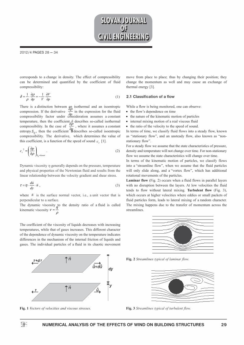
Dynamicviscosityhgenerallydependsonthepressure,temperatureandphysicalpropertiesoftheNewtonianfluidandresultsfromthelinearrelationshipbetweenthevelocitygradientandshearstress.
, (3)
where is the surface normal vector, i.e., aunit vector that isperpendiculartoasurface.The dynamic viscosity to the density ratio of afluid is calledkinematicviscosity
Thecoefficientoftheviscosityofliquidsdecreaseswithincreasingtemperatures,whilethatofgasesincreases.Thisdifferentcharacterofthedependenceofdynamicviscosityonthetemperatureindicatesdifferencesinthemechanismoftheinternalfrictionofliquidsandgases.The individual particles of afluid in its chaoticmovement
move from place to place; thus by changing their position; theychange the momentum as well and may cause an exchange ofthermalenergy[3].
2.1 Classification of a flow
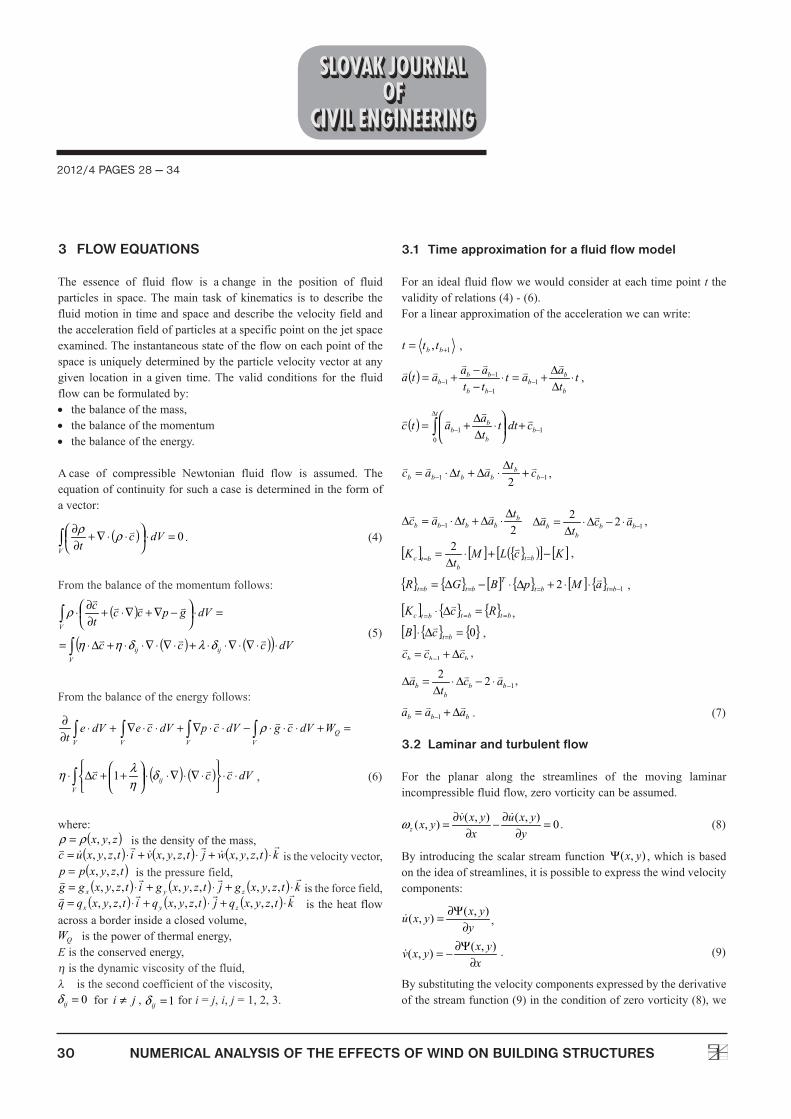
Whileaflowisbeingmonitored,onecanobserve:• theflow’sdependenceontime• thenatureofthekinematicmotionofparticles• internalmixingmotionofarealviscousfluid• theratioofthevelocitytothespeedofsound.Intermsoftime,weclassifyfluidflowsintoasteadyflow,knownas “stationary flow”, and an unsteady flow, also known as “non-stationaryflow”.Forasteadyflowweassumethatthestatecharacteristicsofpressure,densityandtemperaturewillnotchangeovertime.Fornon-stationaryflowweassumethestatecharacteristicswillchangeovertime.In terms of the kinematic motion of particles, we classify flowsinto a“streamline flow”,whenwe assume that the fluid particleswill only slide along, and a“vortex flow”, which has additionalrotationalmovementsoftheparticles.Laminar flow(Fig.2)occurswhenafluidflowsinparallellayerswith no disruption between the layers.At lowvelocities the fluidtends to flow without lateral mixing. Turbulent flow (Fig. 3),whichoccursathighervelocitieswhereeddiesorsmallpacketsoffluidparticles form, leads to lateralmixingofarandomcharacter.Themixing happens due to the transfer ofmomentum across thestreamlines.
Fig. 1 Vectors of velocities and viscous stresses.
Fig. 2 Streamlines typical of laminar flow.
Fig. 3 Streamlines typical of turbulent flow.
30 NUMERICAL ANALYSIS OF THE EFFECTS OF WIND ON BUILDING STRUCTURES
2012/4 PAGES 28 — 34
3 FLOW EQUATIONS
The essence of fluid flow is achange in the position of fluidparticles in space.Themain task of kinematics is to describe thefluidmotionintimeandspaceanddescribethevelocityfieldandtheaccelerationfieldofparticlesataspecificpointonthejetspaceexamined.Theinstantaneousstateoftheflowoneachpointofthespaceisuniquelydeterminedbytheparticlevelocityvectoratanygiven location in agiven time.The valid conditions for the fluidflowcanbeformulatedby:• thebalanceofthemass,• thebalanceofthemomentum• thebalanceoftheenergy.
Acase of compressible Newtonian fluid flow is assumed. Theequationofcontinuityforsuchacaseisdeterminedintheformofavector:
. (4)
From thebalanceofthemomentumfollows:
(5)
From thebalanceoftheenergyfollows:
, (6)
where:isthedensityofthemass,
isthevelocityvector,isthepressurefield,
istheforcefield, is theheatflow
acrossaborderinsideaclosedvolume,isthepowerofthermalenergy,
Eistheconservedenergy,histhedynamicviscosityofthefluid,l isthesecondcoefficientoftheviscosity,
for , fori=j,i,j=1,2,3.
3.1 Time approximation for a fluid flow model
Foranidealfluidflowwewouldconsiderateachtimepointt thevalidityofrelations(4)-(6).Foralinearapproximationoftheaccelerationwecanwrite:
,
,
,
,
,
,
,
,
,
,
. (7)
3.2 Laminar and turbulent flow
For the planar along the streamlines of the moving laminarincompressiblefluidflow,zerovorticitycanbeassumed.
. (8)
Byintroducingthescalarstreamfunction ,whichisbasedontheideaofstreamlines,itispossibletoexpressthewindvelocitycomponents:
,
. (9)
Bysubstitutingthevelocitycomponentsexpressedbythederivativeofthestreamfunction(9)intheconditionofzerovorticity(8),we
2012/4 PAGES 28 — 34
31NUMERICAL ANALYSIS OF THE EFFECTS OF WIND ON BUILDING STRUCTURES
canassumetheequationforthelaminarflowasfollows:
. (10)
In areas of the extreme gradient of the velocity vector behindabarrier,abackflowduetothevorticityofthewindandturbulentwindflowcanbeexpected(Fig.4).
Forplanarstationaryincompressiblefluidflowequationsofmotionwilltaketheform:
,
. (11)
Togetherwiththeequationofcontinuity,
(12)
we will obtain three differential equations for three unknownvariables , ,p.
4. EXPERIMENTAL MEASUREMENTS
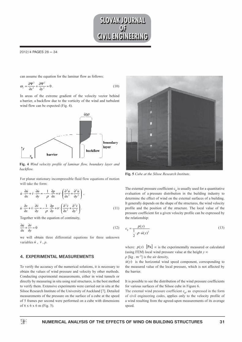
Toverifytheaccuracyofthenumericalsolutions,itisnecessarytoobtainthevaluesofwindpressureandvelocitybyothermethods.Conductingexperimentalmeasurements,either inwind tunnelsordirectlybymeasuringinsituusingrealstructures,isthebestmethodtoverifythem.ExtensiveexperimentswerecarriedoutinsituattheSilsoeResearchInstituteoftheUniversityofAuckland[7].Detailedmeasurementsofthepressureonthesurfaceofacubeatthespeedof5framespersecondwereperformedonacubewithdimensionsof6x6x6m(Fig.5).
Theexternalpressurecoefficientcpisusuallyusedforaquantitativeevaluation of apressure distribution in the building industry todeterminetheeffectofwindontheexternalsurfacesofabuilding.Itgenerallydependsontheshapeofthestructures,thewindvelocityprofile and the position of the structure. The local value of thepressurecoefficientforagivenvelocityprofilecanbeexpressedbytherelationship:
(13)
where: ∞istheexperimentallymeasuredorcalculated(usingFEM)localwindpressurevalueattheheighty∞r[kg.m–3]istheairdensity,
is the horizontal wind speed component, corresponding tothemeasuredvalueof thelocalpressure,whichisnotaffectedbythebarrier.
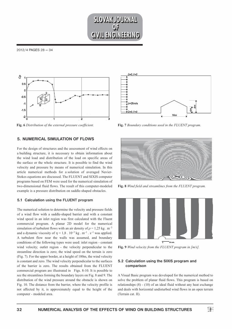
ItispossibletoseethedistributionofthewindpressurecoefficientsforvarioussurfacesoftheSilsoecubeinFigure6.Theexternalwindpressurecoefficientcp,asexpressedintheformof civil engineering codes, applies only to the velocity profile ofawindresultingfromtheagreed-uponmeasurementsofitsaveragespeed.
Fig. 4 Wind velocity profile of laminar flow, boundary layer and backflow.
Fig. 5 Cube at the Silsoe Research Institute.
32 NUMERICAL ANALYSIS OF THE EFFECTS OF WIND ON BUILDING STRUCTURES
2012/4 PAGES 28 — 34
5. NUMERICAL SIMULATION OF FLOWS
Forthedesignofstructuresandtheassessmentofwindeffectsonabuilding structure, it is necessary to obtain information aboutthe wind load and distribution of the load on specific areas ofthesurfaceor thewholestructure.It ispossible tofindthewindvelocity and pressure bymeans of numerical simulation. In thisarticle numerical methods for asolution of averaged Navier-Stokesequationsarediscussed.TheFLUENTandSIXIScomputerprogramsbasedonFEMwereusedforthenumericalsimulationoftwo-dimensionalfluidflows.Theresultofthiscomputer-modeledexampleisapressuredistributiononsaddle-shapedobstacles.
5.1 Calculation using the FLUENT program
Thenumericalsolutiontodeterminethevelocityandpressurefieldsof a wind flowwith a saddle-shaped barrier andwith a constantwind speed inan inlet regionwas first calculatedwith theFluentcommercial program. A planar 2D model for the numericalsimulationofturbulentflowswithanairdensityofr=1,25kg.m–3
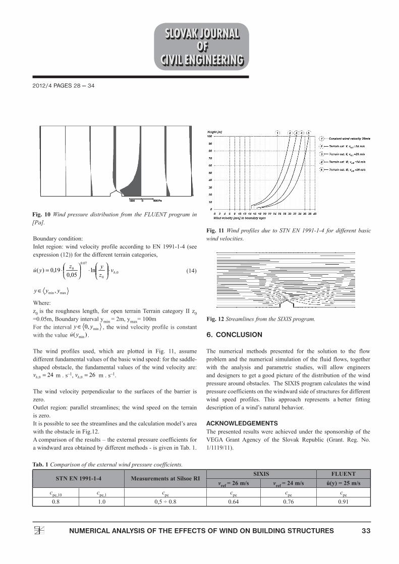
andadynamicviscosityofh=1,8.10–3kg.m–1.s–1wasapplied.A turbulent flow near the walls was assumed, and boundaryconditionsofthefollowingtypeswereused:inletregion-constantwind velocity; outlet region - the velocity perpendicular to thestreamlinedirection is zero; thewind speedon the terrain is zero(Fig.7).Fortheupperborder,ataheightof100m,thewindvelocityisconstantandzero.Thewindvelocityperpendiculartothesurfacesof the barrier is zero. The results obtained from the FLUENTcommercialprogramareillustratedinFigs.8-10.ItispossibletoseethestreamlinesformingtheboundarylayersonFig.8and9.Thedistributionof thewindpressurearound theobstacle is shownonFig.10.Thedistancefromthebarrier,wherethevelocityprofileisnot affected by it, is approximately equal to the height of thecomputer-modeledarea.
5.2 Calculation using the SIXIS program and comparison
AVisualBasicprogramwasdevelopedforthenumericalmethodtosolvetheproblemofplanarfluidflows.Thisprogramisbasedonrelationships(8)-(10)ofanidealfluidwithoutanyheatexchangeanddealswithhorizontalundisturbedwindflowsinanopenterrain(Terraincat.II).
Fig. 6 Distribution of the external pressure coefficient. Fig. 7 Boundary conditions used in the FLUENT program.
Fig. 8 Wind field and streamlines from the FLUENT program.
Fig. 9 Wind velocity from the FLUENT program in [m/s].
2012/4 PAGES 28 — 34
33NUMERICAL ANALYSIS OF THE EFFECTS OF WIND ON BUILDING STRUCTURES
Boundarycondition:Inlet region:windvelocityprofileaccording toEN1991-1-4 (seeexpression(12))forthedifferentterraincategories,
(14)
Where:z0 is the roughness length, for open terrainTerrain category II z0=0.05m,Boundaryintervalymin=2m,ymax=100mFor the interval , thewindvelocityprofile is constantwiththevalue .
The wind profiles used, which are plotted in Fig. 11, assumedifferentfundamentalvaluesofthebasicwindspeed:forthesaddle-shapedobstacle, the fundamentalvaluesof thewindvelocityare:
m.s–1, m.s–1.
The wind velocity perpendicular to the surfaces of the barrier iszero.Outlet region: parallel streamlines; thewind speed on the terrainiszero.Itispossibletoseethestreamlinesandthecalculationmodel’sareawiththeobstacleinFig.12.Acomparisonoftheresults–theexternalpressurecoefficientsforawindwardareaobtainedbydifferentmethods-isgiveninTab.1.
6. CONCLUSION
The numerical methods presented for the solution to the flowproblemand thenumerical simulationof the fluid flows, togetherwith the analysis and parametric studies, will allow engineersanddesignerstogetagoodpictureofthedistributionofthewindpressurearoundobstacles.TheSIXISprogramcalculatesthewindpressurecoefficientsonthewindwardsideofstructuresfordifferentwind speed profiles. This approach represents abetter fittingdescriptionofawind’snaturalbehavior.
ACKNOWLEDGEMENTS Thepresented resultswereachievedunder the sponsorshipof theVEGA Grant Agency of the Slovak Republic (Grant. Reg. No.1/1119/11).
Tab. 1 Comparison of the external wind pressure coefficients.
STN EN 1991-1-4 Measurements at Silsoe RISIXIS FLUENT
vref = 26 m/s vref = 24 m/s ů(y) = 25 m/scpe,10 cpe,1 cpe cpe cpe cpe0.8 1.0 0,5÷0.8 0.64 0.76 0.91
Fig. 10 Wind pressure distribution from the FLUENT program in [Pa].
Fig. 11 Wind profiles due to STN EN 1991-1-4 for different basic wind velocities.
Fig. 12 Streamlines from the SIXIS program.

34 NUMERICAL ANALYSIS OF THE EFFECTS OF WIND ON BUILDING STRUCTURES
2012/4 PAGES 28 — 34
REFERENCES
[1] Dvořák,R.,Kozel,K.:Matematickémodelovánívaerodynamice(Mathematicalmodelingof aerodynamics),Prague,1996.
[2] Easom, G.J.: Improved turbulence models for computationalwindengineering,PhD.Thesis
inCivilEngineering,UniversityofNottingham,UK,2000.[3] Horák, Z., Krupka, F.: Fyzika -Příručka pro vysoké školy
(Physics-Handbookforuniversities),Prague,1976.[4] Krempaský, J.: Fyzika - Príručka pre vysoké školy technické
(Physics - Handbook for Technical Universities), Bratislava,1982.
[5] EN1991-1-4:Eurocode1:Actiononstructures,Parts1-4Windactions,2005.
[6] Hubová, O.: The Effect of the Wind on aStructure, SlovakJournalofCivilEngineering2007/3,Vol.XV,ISSN1210-3896,2007.
[7] Richards, P. J., Hoxey, R. P., Short, L. J.: Wind pressureson a6 m cube, Journal of Wind Engineering and IndustrialAerodynamics,Vol.89,Issues14–15,2001,pp.1553–1564,ELSEVIER.