Embed Size (px)
Citation preview
Answers for energy.
www.siemens.com/energy/arrester
3EK7 Medium Voltage Silicone Insulated Surge Arresters
2
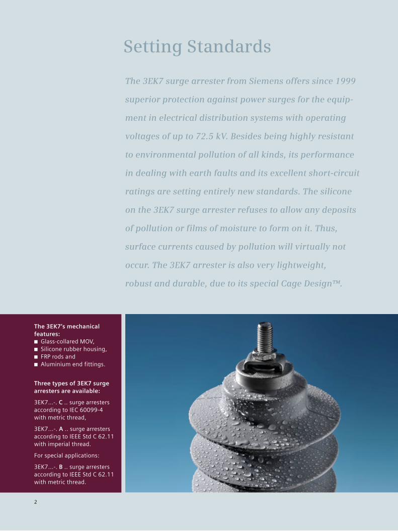
The 3EK7 surge arrester from Siemens offers since 1999
superior protection against power surges for the equip-
ment in electrical distribution systems with operating
voltages of up to 72.5 kV. Besides being highly resistant
to environmental pollution of all kinds, its performance
in dealing with earth faults and its excellent short-circuit
ratings are setting entirely new standards. The silicone
on the 3EK7 surge arrester refuses to allow any deposits
of pollution or films of moisture to form on it. Thus,
surface currents caused by pollution will virtually not
occur. The 3EK7 arrester is also very lightweight,
robust and durable, due to its special Cage Design™.
Setting Standards
The 3EK7’s mechanical features:
■ Glass-collared MOV, ■ Silicone rubber housing, ■ FRP rods and ■ Aluminium end fittings.
Three types of 3EK7 surge arresters are available:
3EK7…-. C .. surge arresters according to IEC 60099-4 with metric thread,
3EK7...-. A .. surge arresters according to IEEE Std C 62.11 with imperial thread.
For special applications:
3EK7...-. B .. surge arresters according to IEEE Std C 62.11 with metric thread.
3
3EK7 Design
3EK7 a top quality product
■ The silicone rubber housing is molded directly onto the MOV blocks and the protection cage. It provides an excellent sealing system against moisture ingress and partial discharges. In addition, the MOV blocks are glass-collared to prevent aging.
■ Highest quality materials. Silicone rubber is highly hydrophobic and maintains this ability to repel water and any deposits of pollution throughout its entire service life. This results in high tracking and erosion resistance. Furthermore, the silicone rubber housing is self-extinguishing and flame-retardant. These advan-tages provide maintenance free and reliable service life for 3EK7 arresters.
■ Manufacturing plants are certified under ISO 9001 and ISO 14001.
■ 3EK7 arresters have been type tested by an indepen-dent test laboratory.
Secure and reliable design
■ The 3EK7 series is based on a cage of pre-stressed fiber-reinforced plastic rods for high mechanical strength, reducing the risk of internal components being ejected. In the extremely rare event of the resistors being over-loaded, arcing cannot result in a build-up of critical
internal pressure, since the resistors are not enclosed in a sealed mechanical shell. Thus, the arc can escape through the silicone sheath, leaving the mechanical support structure of the enclosure unharmed.
■ The cage is lightweight design and yet it offers excel-lent torsional, tensile and cantilever strength: Maximum working cantilever strength of 350 Nm.
■ Silicone rubber is resistant to UV and ozone exposure as well as to all common organic and non-organic solvents and cleaning agents. Therefore, the 3EK7 is suitable for any environmental conditions of industrial areas as well as in desert or coastal regions.
■ 3EK7 arresters are suitable for a temperature range from –55° C to +60° C.
■ Application altitude up to 3600 m a.s.l.
Fast delivery
■ Flexibility in production and in our global network of service and sales facilities provide fast and prompt supply.
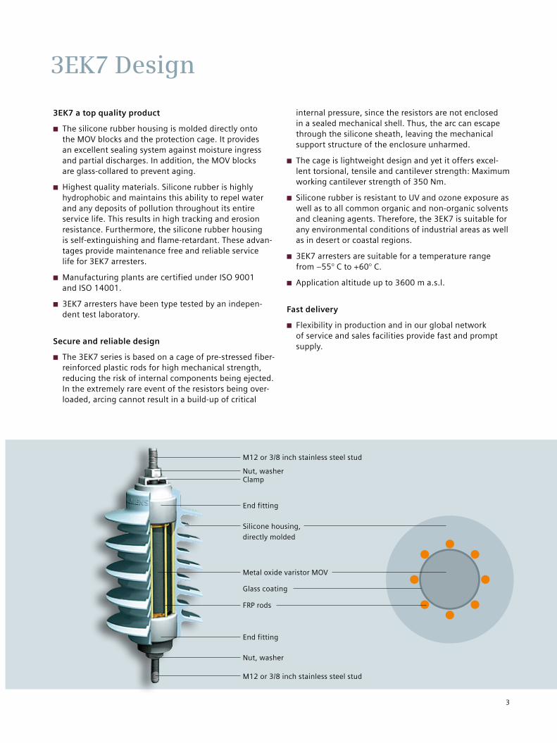
M12 or 3/8 inch stainless steel stud
End fitting
Silicone housing, directly molded
Metal oxide varistor MOV
FRP rods
End fitting
M12 or 3/8 inch stainless steel stud
ClampNut, washer
Nut, washer
Glass coating
4
Selection and Main Data
3EK7 Arresters According to IEC 60099-4
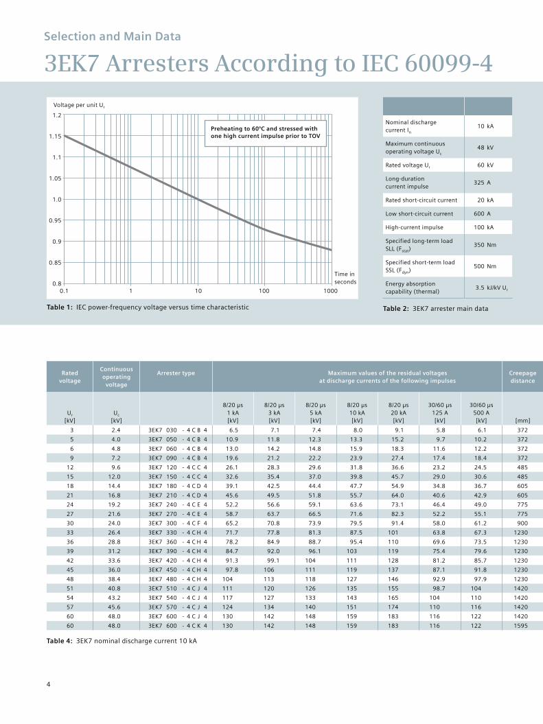
Table 1: IEC power-frequency voltage versus time characteristic
Nominal discharge current In
10 kA
Maximum continuous operating voltage Uc
48 kV
Rated voltage Ur 60 kV
Long-duration current impulse
325 A
Rated short-circuit current 20 kA
Low short-circuit current 600 A
High-current impulse 100 kA
Specified long-term load SLL (Fstat)
350 Nm
Specified short-term load SSL (Fdyn)
500 Nm
Energy absorption capability (thermal)
3.5 kJ/kV Ur
Rated voltage
Continuous operating
voltage
Arrester type Maximum values of the residual voltages at discharge currents of the following impulses
Creepage distance
Flashoverdistance
Housing insulation
Specified short-term
load SSL (Fdyn)
Specified long-term
load SLL (Fstat)
Height“H” 1) Weight
Ur
[kV]Uc
[kV]
8/20 µs1 kA[kV]
8/20 µs3 kA[kV]
8/20 µs5 kA[kV]
8/20 µs10 kA[kV]
8/20 µs20 kA[kV]
30/60 µs125 A[kV]
30/60 µs500 A[kV] [mm] [mm]
Lightning impulse withstand voltage
1.2/50 µs[kV]
Power frequency withstand voltage
1 min., wet[kV] [N] [N] [mm] [kg]
3 2.4 3EK7 030 - 4 C B 4 6.5 7.1 7.4 8.0 9.1 5.8 6.1 372 180 104 49 2940 2050 170 1.5
5 4.0 3EK7 050 - 4 C B 4 10.9 11.8 12.3 13.3 15.2 9.7 10.2 372 180 104 49 2940 2050 170 1.5
6 4.8 3EK7 060 - 4 C B 4 13.0 14.2 14.8 15.9 18.3 11.6 12.2 372 180 104 49 2940 2050 170 1.6
9 7.2 3EK7 090 - 4 C B 4 19.6 21.2 22.2 23.9 27.4 17.4 18.4 372 180 104 49 2940 2050 170 1.6
12 9.6 3EK7 120 - 4 C C 4 26.1 28.3 29.6 31.8 36.6 23.2 24.5 485 210 122 57 2500 1750 200 1.9
15 12.0 3EK7 150 - 4 C C 4 32.6 35.4 37.0 39.8 45.7 29.0 30.6 485 210 122 57 2500 1750 200 2.0
18 14.4 3EK7 180 - 4 C D 4 39.1 42.5 44.4 47.7 54.9 34.8 36.7 605 248 144 67 2080 1450 240 2.3
21 16.8 3EK7 210 - 4 C D 4 45.6 49.5 51.8 55.7 64.0 40.6 42.9 605 248 144 67 2080 1450 240 2.4
24 19.2 3EK7 240 - 4 C E 4 52.2 56.6 59.1 63.6 73.1 46.4 49.0 775 286 166 77 1850 1290 270 2.7
27 21.6 3EK7 270 - 4 C E 4 58.7 63.7 66.5 71.6 82.3 52.2 55.1 775 286 166 77 1850 1290 270 2.8
30 24.0 3EK7 300 - 4 C F 4 65.2 70.8 73.9 79.5 91.4 58.0 61.2 900 318 184 86 1660 1160 300 3.1
33 26.4 3EK7 330 - 4 C H 4 71.7 77.8 81.3 87.5 101 63.8 67.3 1230 418 242 113 1250 870 400 3.9
36 28.8 3EK7 360 - 4 C H 4 78.2 84.9 88.7 95.4 110 69.6 73.5 1230 418 242 113 1250 870 400 4.0
39 31.2 3EK7 390 - 4 C H 4 84.7 92.0 96.1 103 119 75.4 79.6 1230 418 242 113 1250 870 400 4.1
42 33.6 3EK7 420 - 4 C H 4 91.3 99.1 104 111 128 81.2 85.7 1230 418 242 113 1250 870 400 4.1
45 36.0 3EK7 450 - 4 C H 4 97.8 106 111 119 137 87.1 91.8 1230 418 242 113 1250 870 400 4.2
48 38.4 3EK7 480 - 4 C H 4 104 113 118 127 146 92.9 97.9 1230 418 242 113 1250 870 400 4.3
51 40.8 3EK7 510 - 4 C J 4 111 120 126 135 155 98.7 104 1420 484 281 131 1060 740 470 4.9
54 43.2 3EK7 540 - 4 C J 4 117 127 133 143 165 104 110 1420 484 281 131 1060 740 470 5.0
57 45.6 3EK7 570 - 4 C J 4 124 134 140 151 174 110 116 1420 484 281 131 1060 740 470 5.0
60 48.0 3EK7 600 - 4 C J 4 130 142 148 159 183 116 122 1420 484 281 131 1060 740 470 5.1
60 48.0 3EK7 600 - 4 C K 4 130 142 148 159 183 116 122 1595 520 302 140 980 680 510 5.3
Table 2: 3EK7 arrester main data
Table 4: 3EK7 nominal discharge current 10 kA
Voltage per unit Ur
1.15
1.1
1.05
1.0
0.95
0.9
0.85
0.1 1 10
1.2
0.8
Time in seconds
Preheating to 60°C and stressed with one high current impulse prior to TOV
100 1000
5
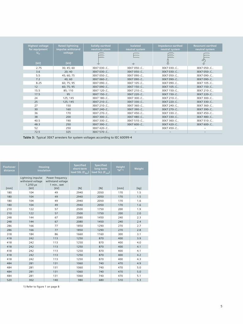
Highest voltage for equipment
Um
[kV]
Rated lightning impulse withstand
voltage
[kV]
Solidly earthed neutral system
Isolated neutral system
Impedance earthed neutral system
Resonant earthed neutral system
2.75 30; 45; 60 3EK7 030-.C.. 3EK7 050-.C.. 3EK7 030-.C.. 3EK7 050-.C..3.6 20; 40 3EK7 030-.C.. 3EK7 050-.C.. 3EK7 030-.C.. 3EK7 050-.C..5.5 45; 60; 75 3EK7 050-.C.. 3EK7 090-.C.. 3EK7 050-.C.. 3EK7 090-.C..7.2 40; 60 3EK7 060-.C.. 3EK7 090-.C.. 3EK7 090-.C.. 3EK7 090-.C..8.25 60; 75; 95 3EK7 090-.C.. 3EK7 105-.C.. 3EK7 090-.C.. 3EK7 105-.C..
12 60; 75; 95 3EK7 090-.C.. 3EK7 150-.C.. 3EK7 105-.C.. 3EK7 150-.C..15.5 85; 110 3EK7 120-.C.. 3EK7 210-.C.. 3EK7 150-.C.. 3EK7 210-.C..17.5 95 3EK7 150-.C.. 3EK7 220-.C.. 3EK7 150-.C.. 3EK7 220-.C..24 125; 145 3EK7 180-.C.. 3EK7 300-.C.. 3EK7 210-.C.. 3EK7 300-.C..25 125; 145 3EK7 210-.C.. 3EK7 330-.C.. 3EK7 220-.C.. 3EK7 330-.C..27 150 3EK7 210-.C.. 3EK7 360-.C.. 3EK7 240-.C.. 3EK7 360-.C..30 160 3EK7 240-.C.. 3EK7 390-.C.. 3EK7 270-.C.. 3EK7 390-.C..36 170 3EK7 270-.C.. 3EK7 450-.C.. 3EK7 330-.C.. 3EK7 450-.C..38 200 3EK7 300-.C.. 3EK7 480-.C.. 3EK7 330-.C.. 3EK7 480-.C..40.5 190 3EK7 330-.C.. 3EK7 510-.C.. 3EK7 360-.C.. 3EK7 510-.C..48.3 250 3EK7 390-.C.. 3EK7 600-.C.. 3EK7 420-.C.. 3EK7 600-.C..52 250 3EK7 420-.C.. – 3EK7 450-.C.. –72.5 325 3EK7 570-.C.. – – –
Rated voltage
Continuous operating
voltage
Arrester type Maximum values of the residual voltages at discharge currents of the following impulses
Creepage distance
Flashoverdistance
Housing insulation
Specified short-term
load SSL (Fdyn)
Specified long-term
load SLL (Fstat)
Height“H” 1) Weight
Ur
[kV]Uc
[kV]
8/20 µs1 kA[kV]
8/20 µs3 kA[kV]
8/20 µs5 kA[kV]
8/20 µs10 kA[kV]
8/20 µs20 kA[kV]
30/60 µs125 A[kV]
30/60 µs500 A[kV] [mm] [mm]
Lightning impulse withstand voltage
1.2/50 µs[kV]
Power frequency withstand voltage
1 min., wet[kV] [N] [N] [mm] [kg]
3 2.4 3EK7 030 - 4 C B 4 6.5 7.1 7.4 8.0 9.1 5.8 6.1 372 180 104 49 2940 2050 170 1.5
5 4.0 3EK7 050 - 4 C B 4 10.9 11.8 12.3 13.3 15.2 9.7 10.2 372 180 104 49 2940 2050 170 1.5
6 4.8 3EK7 060 - 4 C B 4 13.0 14.2 14.8 15.9 18.3 11.6 12.2 372 180 104 49 2940 2050 170 1.6
9 7.2 3EK7 090 - 4 C B 4 19.6 21.2 22.2 23.9 27.4 17.4 18.4 372 180 104 49 2940 2050 170 1.6
12 9.6 3EK7 120 - 4 C C 4 26.1 28.3 29.6 31.8 36.6 23.2 24.5 485 210 122 57 2500 1750 200 1.9
15 12.0 3EK7 150 - 4 C C 4 32.6 35.4 37.0 39.8 45.7 29.0 30.6 485 210 122 57 2500 1750 200 2.0
18 14.4 3EK7 180 - 4 C D 4 39.1 42.5 44.4 47.7 54.9 34.8 36.7 605 248 144 67 2080 1450 240 2.3
21 16.8 3EK7 210 - 4 C D 4 45.6 49.5 51.8 55.7 64.0 40.6 42.9 605 248 144 67 2080 1450 240 2.4
24 19.2 3EK7 240 - 4 C E 4 52.2 56.6 59.1 63.6 73.1 46.4 49.0 775 286 166 77 1850 1290 270 2.7
27 21.6 3EK7 270 - 4 C E 4 58.7 63.7 66.5 71.6 82.3 52.2 55.1 775 286 166 77 1850 1290 270 2.8
30 24.0 3EK7 300 - 4 C F 4 65.2 70.8 73.9 79.5 91.4 58.0 61.2 900 318 184 86 1660 1160 300 3.1
33 26.4 3EK7 330 - 4 C H 4 71.7 77.8 81.3 87.5 101 63.8 67.3 1230 418 242 113 1250 870 400 3.9
36 28.8 3EK7 360 - 4 C H 4 78.2 84.9 88.7 95.4 110 69.6 73.5 1230 418 242 113 1250 870 400 4.0
39 31.2 3EK7 390 - 4 C H 4 84.7 92.0 96.1 103 119 75.4 79.6 1230 418 242 113 1250 870 400 4.1
42 33.6 3EK7 420 - 4 C H 4 91.3 99.1 104 111 128 81.2 85.7 1230 418 242 113 1250 870 400 4.1
45 36.0 3EK7 450 - 4 C H 4 97.8 106 111 119 137 87.1 91.8 1230 418 242 113 1250 870 400 4.2
48 38.4 3EK7 480 - 4 C H 4 104 113 118 127 146 92.9 97.9 1230 418 242 113 1250 870 400 4.3
51 40.8 3EK7 510 - 4 C J 4 111 120 126 135 155 98.7 104 1420 484 281 131 1060 740 470 4.9
54 43.2 3EK7 540 - 4 C J 4 117 127 133 143 165 104 110 1420 484 281 131 1060 740 470 5.0
57 45.6 3EK7 570 - 4 C J 4 124 134 140 151 174 110 116 1420 484 281 131 1060 740 470 5.0
60 48.0 3EK7 600 - 4 C J 4 130 142 148 159 183 116 122 1420 484 281 131 1060 740 470 5.1
60 48.0 3EK7 600 - 4 C K 4 130 142 148 159 183 116 122 1595 520 302 140 980 680 510 5.3
Table 3: Typical 3EK7 arresters for system voltages according to IEC 60099-4
1) Refer to figure 1 on page 8
6
Selection and Main Data
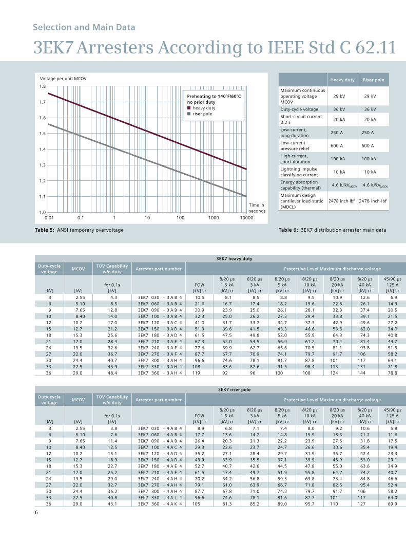
3EK7 Arresters According to IEEE Std C 62.11
Table 5: ANSI temporary overvoltage
Heavy duty Riser pole
Maximum continuous operating voltage MCOV
29 kV 29 kV
Duty-cycle voltage 36 kV 36 kV
Short-circuit current 0.2 s
20 kA 20 kA
Low-current, long-duration
250 A 250 A
Low-current pressure relief
600 A 600 A
High-current, short-duration
100 kA 100 kA
Lightning impulse classifying current
10 kA 10 kA
Energy absorption capability (thermal)
4.6 kJ/kVMCOV 4.6 kJ/kVMCOV
Maximum design cantilever load-static (MDCL)
2478 inch-lbf 2478 inch-lbf
Table 6: 3EK7 distribution arrester main data
3EK7 heavy duty
Duty-cycle voltage
MCOVTOV Capability
w/o dutyArrester part number Protective Level Maximum discharge voltage
Creepage distance
Flashoverdistance
Power frequency with-stand voltage 1 min., wet
Lightning impulse with-stand voltage 1.2/50 µs
Height“H” 1) Weight
[kV] [kV]for 0.1s
[kV]FOW
[kV] cr
8/20 µs1.5 kA[kV] cr
8/20 µs3 kA
[kV] cr
8/20 µs5 kA
[kV] cr
8/20 µs10 kA[kV] cr
8/20 µs20 kA[kV] cr
8/20 µs40 kA[kV] cr
45/90 µs125 A[kV] cr
45/90 µs500 A[kV] cr [inch] [inch] [kV] [kV] [inch] [lbs]
3 2.55 4.3 3EK7 030 - 3 A B 4 10.5 8.1 8.5 8.8 9.5 10.9 12.6 6.9 7.3 14.65 7.09 49 104 6.69 2.86 5.10 8.5 3EK7 060 - 3 A B 4 21.6 16.7 17.4 18.2 19.6 22.5 26.1 14.3 15.1 14.65 7.09 49 104 6.69 3.29 7.65 12.8 3EK7 090 - 3 A B 4 30.9 23.9 25.0 26.1 28.1 32.3 37.4 20.5 21.6 14.65 7.09 49 104 6.69 3.2
10 8.40 14.0 3EK7 100 - 3 A B 4 32.3 25.0 26.2 27.3 29.4 33.8 39.1 21.5 22.6 14.65 7.09 49 104 6.69 3.512 10.2 17.0 3EK7 120 - 3 A C 4 41.0 31.7 33.2 34.7 37.3 42.9 49.6 27.2 28.7 19.09 8.27 57 122 7.87 4.115 12.7 21.2 3EK7 150 - 3 A D 4 51.3 39.6 41.5 43.3 46.6 53.6 62.0 34.0 35.9 23.82 9.76 67 144 9.45 5.118 15.3 25.6 3EK7 180 - 3 A D 4 61.5 47.5 49.8 52.0 55.9 64.3 74.3 40.8 43.0 23.82 9.76 67 144 9.45 5.421 17.0 28.4 3EK7 210 - 3 A E 4 67.3 52.0 54.5 56.9 61.2 70.4 81.4 44.7 47.1 30.51 11.26 77 166 10.63 6.124 19.5 32.6 3EK7 240 - 3 A F 4 77.6 59.9 62.7 65.6 70.5 81.1 93.8 51.5 54.3 35.43 12.52 86 184 11.81 6.727 22.0 36.7 3EK7 270 - 3 A F 4 87.7 67.7 70.9 74.1 79.7 91.7 106 58.2 61.4 35.43 12.52 86 184 11.81 7.030 24.4 40.7 3EK7 300 - 3 A H 4 96.6 74.6 78.1 81.7 87.8 101 117 64.1 67.6 48.43 16.46 113 242 15.75 8.233 27.5 45.9 3EK7 330 - 3 A H 4 108 83.6 87.6 91.5 98.4 113 131 71.8 75.8 48.43 16.46 113 242 15.75 8.536 29.0 48.4 3EK7 360 - 3 A H 4 119 92 96 100 108 124 144 78.8 83.2 48.43 16.46 113 242 15.75 8.9
3EK7 riser pole
Duty-cycle voltage
MCOVTOV Capability
w/o dutyArrester part number Protective Level Maximum discharge voltage
Creepage distance
Flashoverdistance
Power frequency with-stand voltage 1 min., wet
Lightning impulse with-stand voltage 1.2/50 µs
Height“H” 1) Weight
[kV] [kV]for 0.1s
[kV]FOW
[kV] cr
8/20 µs1.5 kA[kV] cr
8/20 µs3 kA
[kV] cr
8/20 µs5 kA
[kV] cr
8/20 µs10 kA[kV] cr
8/20 µs20 kA[kV] cr
8/20 µs40 kA[kV] cr
45/90 µs125 A[kV] cr
45/90 µs500 A[kV] cr [inch] [inch] [kV] [kV] [inch] [lbs]
3 2.55 3.8 3EK7 030 - 4 A B 4 8.9 6.8 7.1 7.4 8.0 9.2 10.6 5.8 6.1 14.65 7.09 49 104 6.69 2.86 5.10 7.6 3EK7 060 - 4 A B 4 17.7 13.6 14.2 14.8 15.9 18.3 21.2 11.6 12.3 14.65 7.09 49 104 6.69 3.29 7.65 11.4 3EK7 090 - 4 A B 4 26.4 20.3 21.3 22.2 23.9 27.5 31.8 17.5 18.4 14.65 7.09 49 104 6.69 3.5
10 8.40 12.5 3EK7 100 - 4 A C 4 29.3 22.6 23.7 24.7 26.6 30.6 35.4 19.4 20.5 19.09 8.27 57 122 7.87 3.512 10.2 15.1 3EK7 120 - 4 A D 4 35.2 27.1 28.4 29.7 31.9 36.7 42.4 23.3 24.6 23.82 9.76 67 144 9.45 4.115 12.7 18.9 3EK7 150 - 4 A D 4 43.9 33.9 35.5 37.1 39.9 45.9 53.0 29.1 30.7 23.82 9.76 67 144 9.45 4.418 15.3 22.7 3EK7 180 - 4 A E 4 52.7 40.7 42.6 44.5 47.8 55.0 63.6 34.9 36.8 30.51 11.26 77 166 10.63 5.121 17.0 25.2 3EK7 210 - 4 A F 4 61.5 47.4 49.7 51.9 55.8 64.2 74.2 40.7 43.0 35.43 12.52 86 184 11.81 5.424 19.5 29.0 3EK7 240 - 4 A H 4 70.2 54.2 56.8 59.3 63.8 73.4 84.8 46.6 49.1 48.43 16.46 113 242 15.75 6.127 22.0 32.7 3EK7 270 - 4 A H 4 79.1 61.0 63.9 66.7 71.8 82.5 95.4 52.4 55.3 48.43 16.46 113 242 15.75 6.730 24.4 36.2 3EK7 300 - 4 A H 4 87.7 67.8 71.0 74.2 79.7 91.7 106 58.2 61.4 48.43 16.46 113 242 15.75 7.033 27.5 40.8 3EK7 330 - 4 A J 4 96.6 74.6 78.1 81.6 87.7 101 117 64.0 67.5 55.91 19.06 131 281 18.50 8.236 29.0 43.1 3EK7 360 - 4 A K 4 105 81.3 85.2 89.0 95.7 110 127 69.9 73.7 62.80 20.47 140 302 20.08 8.5
Voltage per unit MCOV
1.7
1.6
1.5
1.4
1.3
1.2
1.1
0.01 0.1 1 10
1.8
1.0
Time in seconds
Preheating to 140°F/60°C no prior duty■ heavy duty■ riser pole
100 1000 10000
7
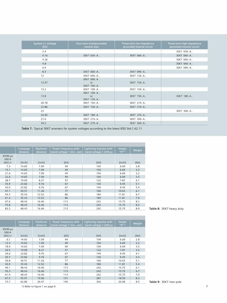
Table 7: Typical 3EK7 arresters for system voltages according to the latest IEEE Std C 62.11
System L-L Voltage [kV]
Four-wire multigrounded neutral wye
Three-wire low impedance grounded neutral circuit
Three-wire high impedancegrounded neutral circuit
2.4 3EK7 030-.A..
4.16 3EK7 030-.A.. 3EK7 060-.A.. 3EK7 060-.A..
4.26 3EK7 060-.A..
4.8 3EK7 060-.A..
6.9 3EK7 090-.A..
8.3 3EK7 060-.A.. 3EK7 090-.A..
12 3EK7 090-.A.. 3EK7 120-.A..
12.473EK7 090-.A..
or 3EK7 100-.A..
3EK7 150-.A..
13.2 3EK7 100-.A.. 3EK7 150-.A..
13.83EK7 100-.A..
or 3EK7 120-.A..
3EK7 150-.A.. 3EK7 180-.A..
20.78 3EK7 150-.A.. 3EK7 210-.A..
22.86 3EK7 150-.A.. 3EK7 210-.A..
23 3EK7 300-.A..
24.94 3EK7 180-.A.. 3EK7 270-.A..
27.6 3EK7 210-.A.. 3EK7 300-.A..
34.5 3EK7 270-.A.. 3EK7 360-.A..
3EK7 heavy duty
Duty-cycle voltage
MCOVTOV Capability
w/o dutyArrester part number Protective Level Maximum discharge voltage
Creepage distance
Flashoverdistance
Power frequency with-stand voltage 1 min., wet
Lightning impulse with-stand voltage 1.2/50 µs
Height“H” 1) Weight
[kV] [kV]for 0.1s
[kV]FOW
[kV] cr
8/20 µs1.5 kA[kV] cr
8/20 µs3 kA
[kV] cr
8/20 µs5 kA
[kV] cr
8/20 µs10 kA[kV] cr
8/20 µs20 kA[kV] cr
8/20 µs40 kA[kV] cr
45/90 µs125 A[kV] cr
45/90 µs500 A[kV] cr [inch] [inch] [kV] [kV] [inch] [lbs]
3 2.55 4.3 3EK7 030 - 3 A B 4 10.5 8.1 8.5 8.8 9.5 10.9 12.6 6.9 7.3 14.65 7.09 49 104 6.69 2.86 5.10 8.5 3EK7 060 - 3 A B 4 21.6 16.7 17.4 18.2 19.6 22.5 26.1 14.3 15.1 14.65 7.09 49 104 6.69 3.29 7.65 12.8 3EK7 090 - 3 A B 4 30.9 23.9 25.0 26.1 28.1 32.3 37.4 20.5 21.6 14.65 7.09 49 104 6.69 3.2
10 8.40 14.0 3EK7 100 - 3 A B 4 32.3 25.0 26.2 27.3 29.4 33.8 39.1 21.5 22.6 14.65 7.09 49 104 6.69 3.512 10.2 17.0 3EK7 120 - 3 A C 4 41.0 31.7 33.2 34.7 37.3 42.9 49.6 27.2 28.7 19.09 8.27 57 122 7.87 4.115 12.7 21.2 3EK7 150 - 3 A D 4 51.3 39.6 41.5 43.3 46.6 53.6 62.0 34.0 35.9 23.82 9.76 67 144 9.45 5.118 15.3 25.6 3EK7 180 - 3 A D 4 61.5 47.5 49.8 52.0 55.9 64.3 74.3 40.8 43.0 23.82 9.76 67 144 9.45 5.421 17.0 28.4 3EK7 210 - 3 A E 4 67.3 52.0 54.5 56.9 61.2 70.4 81.4 44.7 47.1 30.51 11.26 77 166 10.63 6.124 19.5 32.6 3EK7 240 - 3 A F 4 77.6 59.9 62.7 65.6 70.5 81.1 93.8 51.5 54.3 35.43 12.52 86 184 11.81 6.727 22.0 36.7 3EK7 270 - 3 A F 4 87.7 67.7 70.9 74.1 79.7 91.7 106 58.2 61.4 35.43 12.52 86 184 11.81 7.030 24.4 40.7 3EK7 300 - 3 A H 4 96.6 74.6 78.1 81.7 87.8 101 117 64.1 67.6 48.43 16.46 113 242 15.75 8.233 27.5 45.9 3EK7 330 - 3 A H 4 108 83.6 87.6 91.5 98.4 113 131 71.8 75.8 48.43 16.46 113 242 15.75 8.536 29.0 48.4 3EK7 360 - 3 A H 4 119 92 96 100 108 124 144 78.8 83.2 48.43 16.46 113 242 15.75 8.9
3EK7 riser pole
Duty-cycle voltage
MCOVTOV Capability
w/o dutyArrester part number Protective Level Maximum discharge voltage
Creepage distance
Flashoverdistance
Power frequency with-stand voltage 1 min., wet
Lightning impulse with-stand voltage 1.2/50 µs
Height“H” 1) Weight
[kV] [kV]for 0.1s
[kV]FOW
[kV] cr
8/20 µs1.5 kA[kV] cr
8/20 µs3 kA
[kV] cr
8/20 µs5 kA
[kV] cr
8/20 µs10 kA[kV] cr
8/20 µs20 kA[kV] cr
8/20 µs40 kA[kV] cr
45/90 µs125 A[kV] cr
45/90 µs500 A[kV] cr [inch] [inch] [kV] [kV] [inch] [lbs]
3 2.55 3.8 3EK7 030 - 4 A B 4 8.9 6.8 7.1 7.4 8.0 9.2 10.6 5.8 6.1 14.65 7.09 49 104 6.69 2.86 5.10 7.6 3EK7 060 - 4 A B 4 17.7 13.6 14.2 14.8 15.9 18.3 21.2 11.6 12.3 14.65 7.09 49 104 6.69 3.29 7.65 11.4 3EK7 090 - 4 A B 4 26.4 20.3 21.3 22.2 23.9 27.5 31.8 17.5 18.4 14.65 7.09 49 104 6.69 3.5
10 8.40 12.5 3EK7 100 - 4 A C 4 29.3 22.6 23.7 24.7 26.6 30.6 35.4 19.4 20.5 19.09 8.27 57 122 7.87 3.512 10.2 15.1 3EK7 120 - 4 A D 4 35.2 27.1 28.4 29.7 31.9 36.7 42.4 23.3 24.6 23.82 9.76 67 144 9.45 4.115 12.7 18.9 3EK7 150 - 4 A D 4 43.9 33.9 35.5 37.1 39.9 45.9 53.0 29.1 30.7 23.82 9.76 67 144 9.45 4.418 15.3 22.7 3EK7 180 - 4 A E 4 52.7 40.7 42.6 44.5 47.8 55.0 63.6 34.9 36.8 30.51 11.26 77 166 10.63 5.121 17.0 25.2 3EK7 210 - 4 A F 4 61.5 47.4 49.7 51.9 55.8 64.2 74.2 40.7 43.0 35.43 12.52 86 184 11.81 5.424 19.5 29.0 3EK7 240 - 4 A H 4 70.2 54.2 56.8 59.3 63.8 73.4 84.8 46.6 49.1 48.43 16.46 113 242 15.75 6.127 22.0 32.7 3EK7 270 - 4 A H 4 79.1 61.0 63.9 66.7 71.8 82.5 95.4 52.4 55.3 48.43 16.46 113 242 15.75 6.730 24.4 36.2 3EK7 300 - 4 A H 4 87.7 67.8 71.0 74.2 79.7 91.7 106 58.2 61.4 48.43 16.46 113 242 15.75 7.033 27.5 40.8 3EK7 330 - 4 A J 4 96.6 74.6 78.1 81.6 87.7 101 117 64.0 67.5 55.91 19.06 131 281 18.50 8.236 29.0 43.1 3EK7 360 - 4 A K 4 105 81.3 85.2 89.0 95.7 110 127 69.9 73.7 62.80 20.47 140 302 20.08 8.5
Table 8: 3EK7 heavy duty
Table 9: 3EK7 riser pole
1) Refer to figure 1 on page 8
8
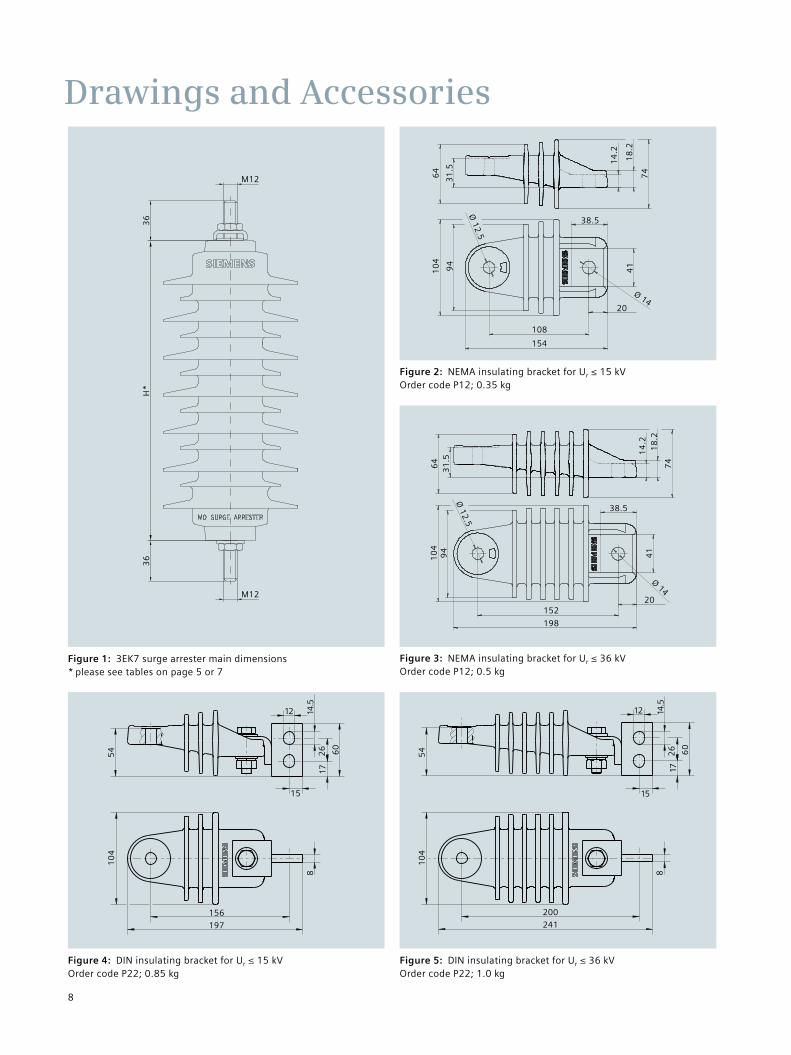
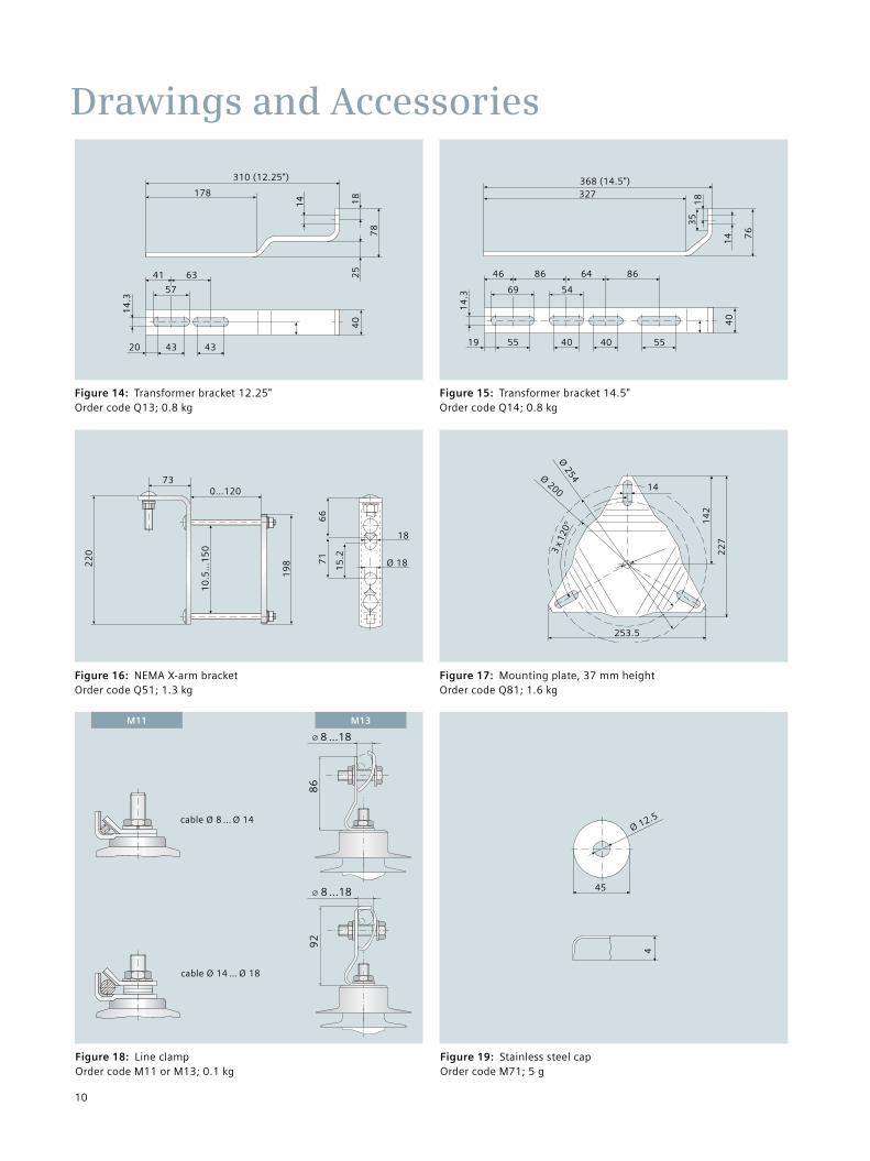
Drawings and Accessories
Figure 4: DIN insulating bracket for Ur ≤ 15 kV Order code P22; 0.85 kg
Figure 5: DIN insulating bracket for Ur ≤ 36 kV Order code P22; 1.0 kg
Figure 2: NEMA insulating bracket for Ur ≤ 15 kV Order code P12; 0.35 kg
Figure 3: NEMA insulating bracket for Ur ≤ 36 kV Order code P12; 0.5 kg
Figure 1: 3EK7 surge arrester main dimensions * please see tables on page 5 or 7
10
4
10
4
156
197
12 12
15
172
6 60
54
8 8
200
15
14.5
14.5
172
6 60
54
241
M12
M12
36
36
H*
64
41
38.5
108
154
20
10
4
31
.59
4
14
.2
18
.2
74
Ø 12.5
Ø 14
64
41
38.5
152
198
20
10
43
1.5
14
.2
74
18
.2
94
Ø 12.5
Ø 14
9
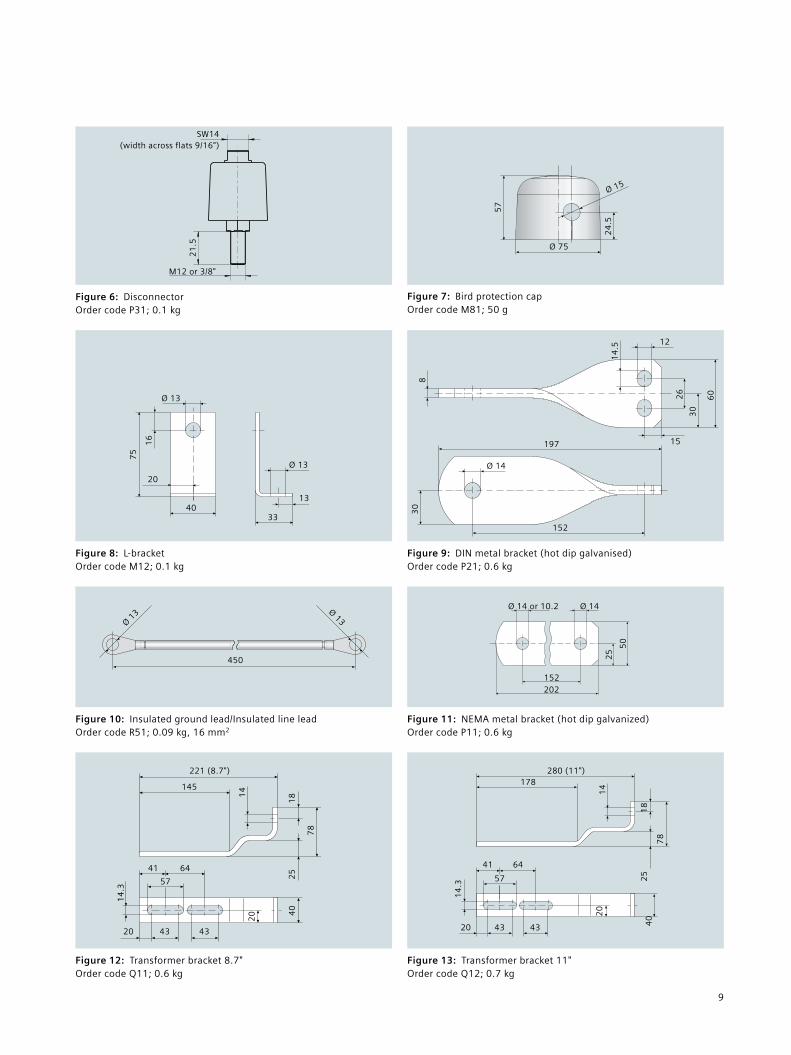
Figure 8: L-bracket Order code M12; 0.1 kg
Figure 9: DIN metal bracket (hot dip galvanised) Order code P21; 0.6 kg
Figure 10: Insulated ground lead/Insulated line lead Order code R51; 0.09 kg, 16 mm2
Figure 11: NEMA metal bracket (hot dip galvanized) Order code P11; 0.6 kg
Figure 12: Transformer bracket 8.7" Order code Q11; 0.6 kg
Figure 13: Transformer bracket 11" Order code Q12; 0.7 kg
Figure 7: Bird protection cap Order code M81; 50 g
Figure 6: Disconnector Order code P31; 0.1 kg
SW14 (width across flats 9/16")
M12 or 3/8"
21
.5
32
43
0(1
5)
(87
)
26
0
20
0
260
Ø ø200
30 60
M12
ø14
(10)
152
202
20
ø10,2
50
25
Ø 14 or 10.2 Ø 142
5
50
152202
32
43
0(1
5)
(87
)
26
0
20
0
260
Ø ø200
30 60
M12
14
18
(41,4) (63,5)
269
144,8
(57,2)
42,920
14
,3
20
(8)
78
,5
25
,4
14
18
78
25
178280 (11")
41 64
57
14
.3
20
434320 40
Ø 13 Ø 13
450
32
43
0(1
5)
(87
)
26
0
20
0
260
Ø ø200
30 60
M12
145
14
221 (8.7")
18
78
2541 64
57
14
.3
20
434320
40
32
43
0(1
5)
(87
)
26
0
20
0
260
Ø ø200
30 60
M12
(41,4) (63,5)
269
221
144,8
14
(57,2)
42,920
14
,3
20 (4
0)
(8)
78
,5
25
,41
8
Ø 13
16
75
20
40
Ø 13
13
33
Ø 14
8
14
.5
12
26
30
60
15197
152
30
32
43
0(1
5)
(87
)
26
0
20
0
260
Ø ø200
30 60
M12
(8)
78
,5
25
,4
(60
)
(214)
(173)
(26
)(1
7)
(15)
Ø 15
24
.5
Ø 75
57
10
Drawings and Accessories
Figure 14: Transformer bracket 12.25" Order code Q13; 0.8 kg
Figure 15: Transformer bracket 14.5" Order code Q14; 0.8 kg
Figure 16: NEMA X-arm bracket Order code Q51; 1.3 kg
Figure 18: Line clamp Order code M11 or M13; 0.1 kg
Figure 19: Stainless steel cap Order code M71; 5 g
Figure 17: Mounting plate, 37 mm height Order code Q81; 1.6 kg
22
0
19
8
10
.5…
15
0
730…120
32
43
0(1
5)
(87
)
26
0
20
0
260
Ø ø200
30 60
M12
178
310 (12.25")
18
78
25
14
41 63
57
14
.3
4343204
0
32
43
0(1
5)
(87
)
26
0
20
0
260
Ø ø200
30 60
M12
(8)
78
,5
25
,4
327368 (14.5")
18
76
35
14
46
69
14
.3
19
40
86 64 86
54
55 40 40 55
ø41M12
M12
20
28
0.9
”
ø0.5”
1.3
”0
.6”
2.1”
6.7”
4.9” 0.8”
1.6
”
2.9
5”
1.56”
1”
2.9
5”
Ø 254
14
22
7
Ø 200
14
2
253.5
3 x
120°
32
43
0(1
5)
(87
)
26
0
20
0
260
Ø ø200
30 60
M12
(8)
78
,5
25
,4
cable Ø 8 … Ø 14
cable Ø 14 … Ø 18
66
71
18
Ø 1815
.2
ø41M12
M12
20
28
0.9
”
ø0.5”
1.3
”0
.6”
2.1”
6.7”
4.9” 0.8”
1.6
”
2.9
5”
1.56”
1”
2.9
5”
Ø 12.5
4
45
M13M113
24
30
(15
)(8
7)
26
0
20
0
260
Ø ø200
30 60
M12
(8)
78
,5
25
,4
8 …18
86
8 …18
92
11
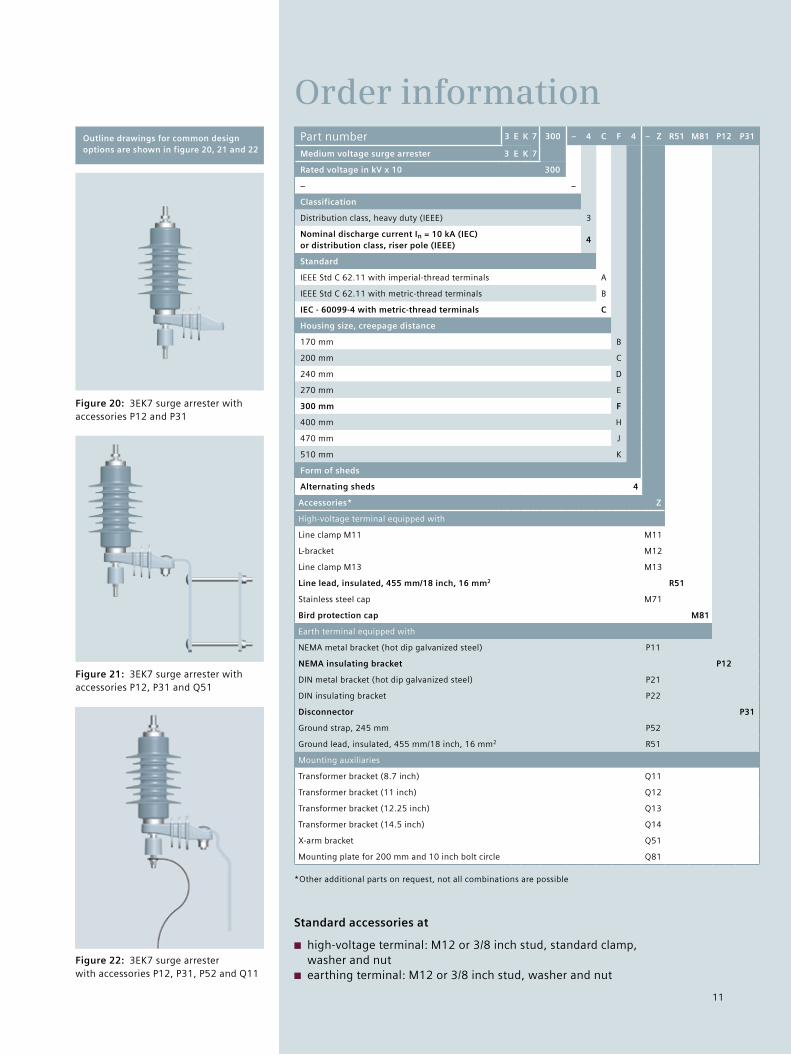
Order information
Figure 22: 3EK7 surge arrester with accessories P12, P31, P52 and Q11
Figure 20: 3EK7 surge arrester with accessories P12 and P31
Figure 21: 3EK7 surge arrester with accessories P12, P31 and Q51
Part number 3 E K 7 300 – 4 C F 4 – Z R51 M81 P12 P31
Medium voltage surge arrester 3 E K 7
Rated voltage in kV x 10 300
– –
Classification
Distribution class, heavy duty (IEEE) 3
Nominal discharge current In = 10 kA (IEC) or distribution class, riser pole (IEEE)
4
Standard
IEEE Std C 62.11 with imperial-thread terminals A
IEEE Std C 62.11 with metric-thread terminals B
IEC - 60099-4 with metric-thread terminals C
Housing size, creepage distance
170 mm B
200 mm C
240 mm D
270 mm E
300 mm F
400 mm H
470 mm J
510 mm K
Form of sheds
Alternating sheds 4
Accessories* Z
High-voltage terminal equipped with
Line clamp M11 M11
L-bracket M12
Line clamp M13 M13
Line lead, insulated, 455 mm/18 inch, 16 mm2 R51
Stainless steel cap M71
Bird protection cap M81
Earth terminal equipped with
NEMA metal bracket (hot dip galvanized steel) P11
NEMA insulating bracket P12
DIN metal bracket (hot dip galvanized steel) P21
DIN insulating bracket P22
Disconnector P31
Ground strap, 245 mm P52
Ground lead, insulated, 455 mm/18 inch, 16 mm2 R51
Mounting auxiliaries
Transformer bracket (8.7 inch) Q11
Transformer bracket (11 inch) Q12
Transformer bracket (12.25 inch) Q13
Transformer bracket (14.5 inch) Q14
X-arm bracket Q51
Mounting plate for 200 mm and 10 inch bolt circle Q81
*Other additional parts on request, not all combinations are possible
Standard accessories at
■ high-voltage terminal: M12 or 3/8 inch stud, standard clamp, washer and nut
■ earthing terminal: M12 or 3/8 inch stud, washer and nut
Outline drawings for common design options are shown in figure 20, 21 and 22
Published by and copyright © 2011: Siemens AG Energy Sector Freyeslebenstrasse 1 91058 Erlangen, Germany
Siemens AG Energy Sector Power Transmission Division High Voltage Products Nonnendammallee 104 13629 Berlin, Germany
www.siemens.com/energy/arrester
Please contact us at: Phone: +49 30 386 33 222 Fax: +49 30 386 26 721 E-mail: [email protected]
Power Transmission Division Order No. E50001-G630-A110-V2-4A00 | Printed in Germany | Dispo 30002 | c4bs No. 7457 | TH 263-110140 | WÜ | 472573 | WS | 11111.0
Printed on elementary chlorine-free bleached paper.
All rights reserved. Trademarks mentioned in this document are the property of Siemens AG, its affiliates, or their respective owners.
Subject to change without prior notice. The information in this document contains general descriptions of the technical options available, which may not apply in all cases. The required technical options should therefore be specified in the contract.


![3EK7 Medium Voltage Silicone Insulated Surge Arresters · Table 3: Typical 3EK7 arresters for system voltages according to IEC 60099-4 Highest voltage for equipment Um [kV] Rated](https://img.pdfslide.us/doc/110x75/5b5ad0607f8b9a55388cf2cb/3ek7-medium-voltage-silicone-insulated-surge-arresters-table-3-typical-3ek7.jpg)