Embed Size (px)
Citation preview
Power Transmission and Distribution
High Voltage Surge Arresters Station Class
Product Overview
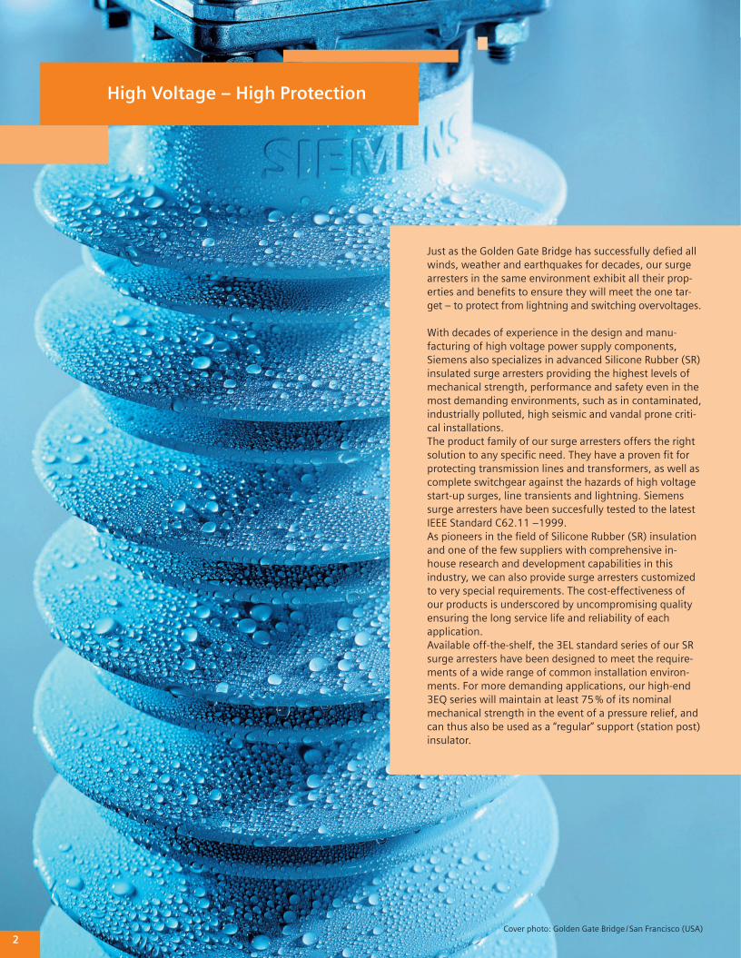
High Voltage – High Protection
Just as the Golden Gate Bridge has successfully defi ed all winds, weather and earthquakes for decades, our surge arresters in the same environment exhibit all their prop-erties and benefi ts to ensure they will meet the one tar-get – to protect from lightning and switching overvoltages.
With decades of experience in the design and manu-facturing of high voltage power supply components, Siemens also specializes in advanced Silicone Rubber (SR) insulated surge arresters providing the highest levels of mechanical strength, performance and safety even in the most demanding environments, such as in contaminated, industrially polluted, high seismic and vandal prone criti-cal installations.The product family of our surge arresters offers the right solution to any specifi c need. They have a proven fi t for protecting transmission lines and transformers, as well as complete switchgear against the hazards of high voltage start-up surges, line transients and lightning. Siemens surge arresters have been succesfully tested to the latest IEEE Standard C62.11 –1999.As pioneers in the fi eld of Silicone Rubber (SR) insulation and one of the few suppliers with comprehensive in-house research and development capabilities in this industry, we can also provide surge arresters customized to very special requirements. The cost-effectiveness of our products is underscored by uncompromising quality ensuring the long service life and reliability of each application.Available off-the-shelf, the 3EL standard series of our SR surge arresters have been designed to meet the require-ments of a wide range of common installation environ-ments. For more demanding applications, our high-end 3EQ series will maintain at least 75 % of its nominal mechanical strength in the event of a pressure relief, and can thus also be used as a “regular” support (station post) insulator.
2Cover photo: Golden Gate Bridge / San Francisco (USA)
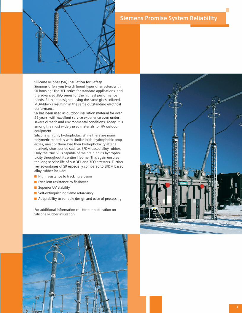
Silicone Rubber (SR) Insulation for SafetySiemens offers you two different types of arresters with SR housing: The 3EL series for standard applications, and the advanced 3EQ series for the highest performance needs. Both are designed using the same glass collared MOV-blocks resulting in the same outstanding electrical performance.SR has been used as outdoor insulation material for over 25 years, with excellent service experience even under severe climatic and environmental conditions. Today, it is among the most widely used materials for HV outdoor equipment.Silicone is highly hydrophobic. While there are many polymeric materials with similar initial hydrophobic prop-erties, most of them lose their hydrophobicity after a relatively short period such as EPDM based alloy rubber. Only the true SR is capable of maintaining its hydropho-bicity throughout its entire lifetime. This again ensures the long service life of our 3EL and 3EQ arresters. Further key advantages of SR especially compared to EPDM based alloy rubber include:
High resistance to tracking erosion
Excellent resistance to fl ashover
Superior UV stability
Self-extinguishing fl ame retardancy
Adaptability to variable design and ease of processing
For additional information call for our publication on Silicone Rubber insulation.
3
Siemens Promise System Reliability
FRP tube design for outstanding mechanical stability (much stronger than porcelain), combined with an excellent sealing system for long-life protection against ingress of mois-ture and partial discharges
Highest level of safety in the event of short circuits from pressure relief devices, no ejection of any internal components
Retention of at least 75 % of initial mechanical strength even after short circuit and thus permit’s the use of the arrester as a support insulator
Weight savings vs. comparable porcelain arresters
Ideal for applications in areas exposed to high seismic activity, heavy wind loads and any other demanding mechanical impact
Available as single-unit arresters rat-ed up to 300 kV or twin-unit arres-tors for up to 550 kV, minimizing the required number of units per stack
High reliability over a wide range of temperatures and extreme tempera-ture changes from –67 F to +122 F (–55 °C to +50 °C)
Total enclosure of all components for protection against partial dis-charges or moisture ingress
High mechanical performance for standard applications
Silicone Rubber shielding provides low-pressure escape of the arc in the event of a short circuit
Signifi cant weight savings vs. com-parable porcelain arresters, facilitat-ing transport and installation of the arresters
Suitable for use as station and/or transmission line arresters
Reliable technology with a proven history of more than 25 years
Optimized glass collared MOV-Block design
Pressure relief system for very fast venting, providing the highest possi-ble means of safety in areas requir-ing special protection
Very high cantilever strength of max. 361110 inch lbs
High-quality components for out-standing overvoltage protection
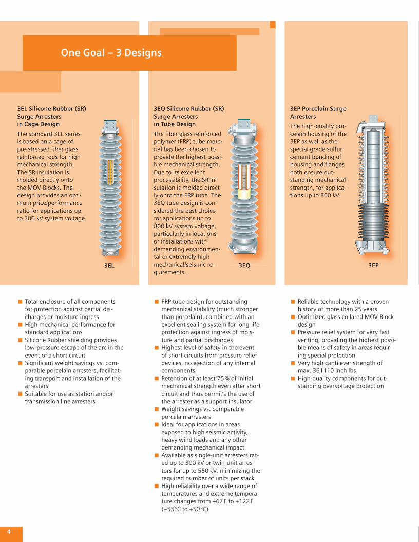
3EP Porcelain Surge Arresters
The high-quality por-celain housing of the 3EP as well as the special grade sulfur cement bonding of housing and fl anges both ensure out-standing mechanical strength, for applica-tions up to 800 kV.
3EL Silicone Rubber (SR) Surge Arresters in Cage Design
The standard 3EL series is based on a cage of pre-stressed fi ber glass reinforced rods for high mechanical strength. The SR insulation is molded directly onto the MOV-Blocks. The design provides an opti-mum price/performance ratio for applications up to 300 kV system voltage.
4
One Goal – 3 Designs
3EP3EL
3EQ Silicone Rubber (SR) Surge Arresters in Tube Design
The fi ber glass reinforced poly mer (FRP) tube mate-rial has been chosen to provide the highest possi-ble mechanical strength. Due to its excellent processi bility, the SR in-sulation is molded direct-ly onto the FRP tube. The 3EQ tube design is con-sidered the best choice for applications up to 800 kV system voltage, particularly in locations or installations with demanding environmen-tal or extremely high mechanical/seismic re-quirements.
3EQ
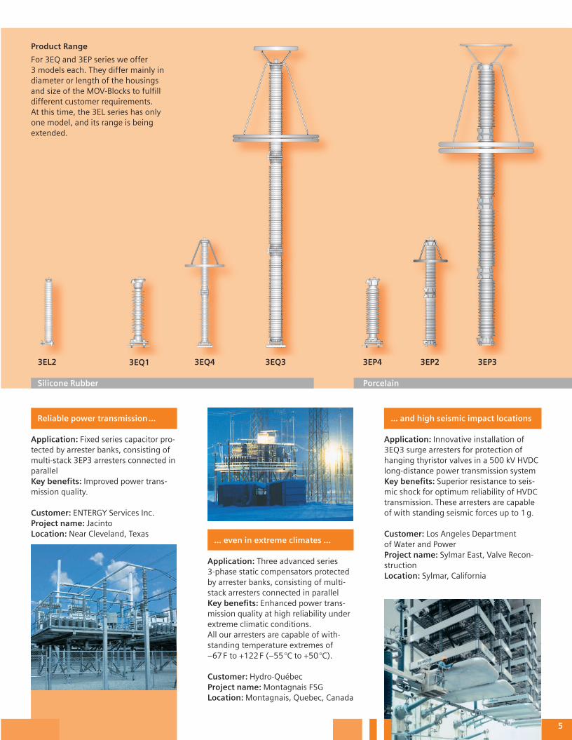
... even in extreme climates ...
Application: Three advanced series 3-phase static compensators protected by arrester banks, consisting of multi-stack arresters connected in parallelKey benefi ts: Enhanced power trans-mission quality at high reliability under extreme climatic conditions. All our arresters are capable of with-standing temperature extremes of –67 F to +122 F (–55 °C to +50 °C). Customer: Hydro-QuébecProject name: Montagnais FSGLocation: Montagnais, Quebec, Canada
Reliable power transmission …
Application: Fixed series capacitor pro-tected by arrester banks, consisting of multi-stack 3EP3 arresters connected in parallelKey benefi ts: Improved power trans-mission quality.
Customer: ENTERGY Services Inc.Project name: JacintoLocation: Near Cleveland, Texas
... and high seismic impact locations
Application: Innovative installation of 3EQ3 surge arresters for protection of hanging thyristor valves in a 500 kV HVDC long-distance power transmission systemKey benefi ts: Superior resistance to seis-mic shock for optimum reliability of HVDC transmission. These arresters are capable of with standing seismic forces up to 1 g.
Customer: Los Angeles Department of Water and PowerProject name: Sylmar East, Valve Recon-structionLocation: Sylmar, California
3EP33EQ4 3EP23EP43EL2
5
Product Range
For 3EQ and 3EP series we offer 3 models each. They differ mainly in diameter or length of the housings and size of the MOV-Blocks to fulfi ll different customer requirements. At this time, the 3EL series has only one model, and its range is being extended.
3EQ33EQ1
Silicone Rubber Porcelain
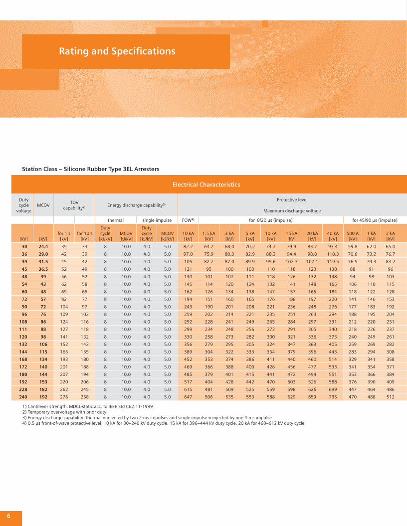
Electrical Characteristics
Dutycycle
voltageMCOV
TOV capability 2) Energy discharge capability 3)
Protective level
Maximum discharge voltage
thermal single impulse FOW 4) for 8/20 µs (impulse) for 45/90 µs (impulse)
[kV] [kV]for 1 s[kV]
for 10 s[kV]
Duty cycle
[kJ/kV]MCOV[kJ/kV]
Duty cycle
[kJ/kV]MCOV[kJ/kV]
10 kA[kV]
1.5 kA[kV]
3 kA[kV]
5 kA[kV]
10 kA[kV]
15 kA[kV]
20 kA[kV]
40 kA[kV]
500 A[kV]
1 kA[kV]
2 kA[kV]
30 24.4 35 33 8 10.0 4.0 5.0 82.2 64.2 68.0 70.2 74.7 79.9 83.7 93.4 59.8 62.0 65.0
36 29.0 42 39 8 10.0 4.0 5.0 97.0 75.9 80.3 82.9 88.2 94.4 98.8 110.3 70.6 73.2 76.7
39 31.5 45 42 8 10.0 4.0 5.0 105 82.2 87.0 89.9 95.6 102.3 107.1 119.5 76.5 79.3 83.2
45 36.5 52 49 8 10.0 4.0 5.0 121 95 100 103 110 118 123 138 88 91 96
48 39 56 52 8 10.0 4.0 5.0 130 101 107 111 118 126 132 148 94 98 103
54 43 62 58 8 10.0 4.0 5.0 145 114 120 124 132 141 148 165 106 110 115
60 48 69 65 8 10.0 4.0 5.0 162 126 134 138 147 157 165 184 118 122 128
72 57 82 77 8 10.0 4.0 5.0 194 151 160 165 176 188 197 220 141 146 153
90 72 104 97 8 10.0 4.0 5.0 243 190 201 208 221 236 248 276 177 183 192
96 76 109 102 8 10.0 4.0 5.0 259 202 214 221 235 251 263 294 188 195 204
108 86 124 116 8 10.0 4.0 5.0 292 228 241 249 265 284 297 331 212 220 231
111 88 127 118 8 10.0 4.0 5.0 299 234 248 256 272 291 305 340 218 226 237
120 98 141 132 8 10.0 4.0 5.0 330 258 273 282 300 321 336 375 240 249 261
132 106 152 142 8 10.0 4.0 5.0 356 279 295 305 324 347 363 405 259 269 282
144 115 165 155 8 10.0 4.0 5.0 389 304 322 333 354 379 396 443 283 294 308
168 134 193 180 8 10.0 4.0 5.0 452 353 374 386 411 440 460 514 329 341 358
172 140 201 188 8 10.0 4.0 5.0 469 366 388 400 426 456 477 533 341 354 371
180 144 207 194 8 10.0 4.0 5.0 485 379 401 415 441 472 494 551 353 366 384
192 153 220 206 8 10.0 4.0 5.0 517 404 428 442 470 503 526 588 376 390 409
228 182 262 245 8 10.0 4.0 5.0 615 481 509 525 559 598 626 699 447 464 486
240 192 276 258 8 10.0 4.0 5.0 647 506 535 553 588 629 659 735 470 488 512
1) Cantilever strength: MDCL-static acc. to IEEE Std C62.11-19992) Temporary overvoltage with prior duty3) Energy discharge capability: thermal = injected by two 2-ms impulses and single impulse = injected by one 4-ms impulse 4) 0.5 µs front-of-wave protective level: 10 kA for 30–240 kV duty cycle, 15 kA for 396–444 kV duty cycle, 20 kA for 468–612 kV duty cycle
6
Rating and Specifi cations
Station Class – Silicone Rubber Type 3EL Arresters
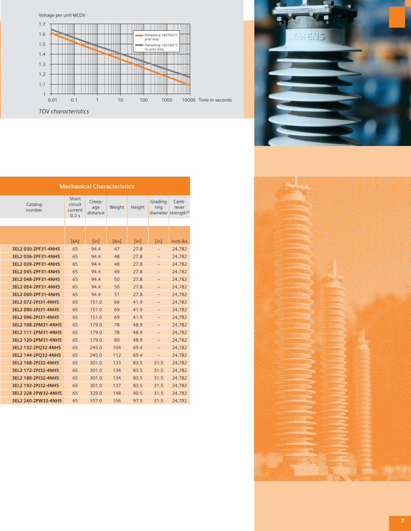
Mechanical Characteristics
Catalog number
Short circuit current
0.2 s
Creep-age
distanceWeight Height
Gradingring
diameter
Canti-lever
strength1)
[kA] [in] [lbs] [in] [in] inch-lbs
3EL2 030-2PF31-4NH5 65 94.4 47 27.8 – 24,782
3EL2 036-2PF31-4NH5 65 94.4 48 27.8 – 24,782
3EL2 039-2PF31-4NH5 65 94.4 48 27.8 – 24,782
3EL2 045-2PF31-4NH5 65 94.4 49 27.8 – 24,782
3EL2 048-2PF31-4NH5 65 94.4 50 27.8 – 24,782
3EL2 054-2PF31-4NH5 65 94.4 50 27.8 – 24,782
3EL2 060-2PF31-4NH5 65 94.4 51 27.8 – 24,782
3EL2 072-2PJ31-4NH5 65 151.0 66 41.9 – 24,782
3EL2 090-2PJ31-4NH5 65 151.0 69 41.9 – 24,782
3EL2 096-2PJ31-4NH5 65 151.0 69 41.9 – 24,782
3EL2 108-2PM31-4NH5 65 179.0 78 48.9 – 24,782
3EL2 111-2PM31-4NH5 65 179.0 78 48.9 – 24,782
3EL2 120-2PM31-4NH5 65 179.0 80 48.9 – 24,782
3EL2 132-2PQ32-4NH5 65 245.0 104 69.4 – 24,782
3EL2 144-2PQ32-4NH5 65 245.0 112 69.4 – 24,782
3EL2 168-2PJ32-4NH5 65 301.0 133 83.5 31.5 24,782
3EL2 172-2PJ32-4NH5 65 301.0 134 83.5 31.5 24,782
3EL2 180-2PJ32-4NH5 65 301.0 134 83.5 31.5 24,782
3EL2 192-2PJ32-4NH5 65 301.0 137 83.5 31.5 24,782
3EL2 228-2PW32-4NH5 65 329.0 148 90.5 31.5 24,782
3EL2 240-2PW32-4NH5 65 357.0 156 97.5 31.5 24,782
TOV characteristics
Time in seconds
Voltage per unit MCOV
Preheating 140 F/60 °Cprior duty
Preheating 140 F/60 °Cno prior duty
1.7
1.6
1.5
1.4
1.3
1.2
1.1
10.01 0.1 1 10 100 1000 10000
7
8
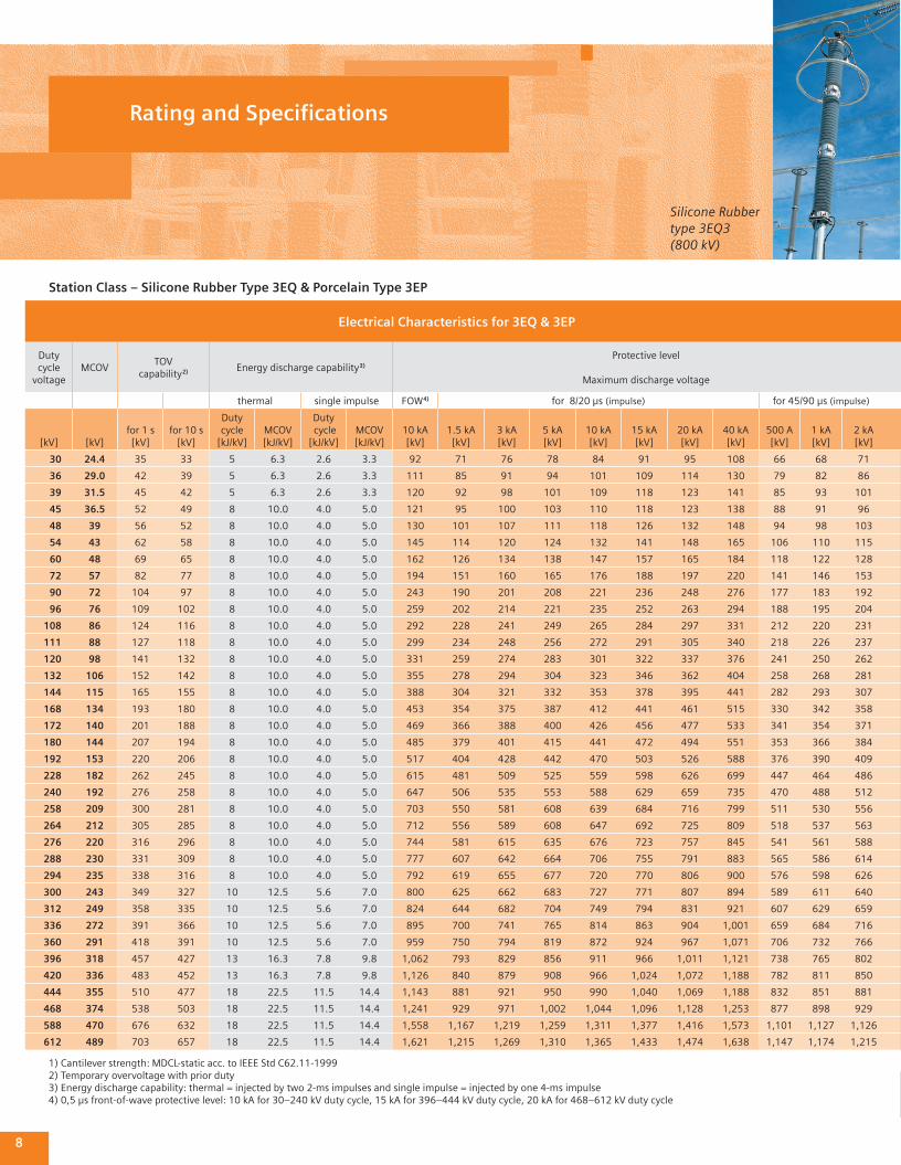
Electrical Characteristics for 3EQ & 3EP
Dutycycle
voltageMCOV
TOV capability 2) Energy discharge capability 3)
Protective level
Maximum discharge voltage
thermal single impulse FOW 4) for 8/20 µs (impulse) for 45/90 µs (impulse)
[kV] [kV]for 1 s[kV]
for 10 s[kV]
Duty cycle
[kJ/kV]MCOV[kJ/kV]
Duty cycle[kJ/kV]
MCOV[kJ/kV]
10 kA[kV]
1.5 kA[kV]
3 kA[kV]
5 kA[kV]
10 kA[kV]
15 kA[kV]
20 kA[kV]
40 kA[kV]
500 A[kV]
1 kA[kV]
2 kA[kV]
30 24.4 35 33 5 6.3 2.6 3.3 92 71 76 78 84 91 95 108 66 68 71
36 29.0 42 39 5 6.3 2.6 3.3 111 85 91 94 101 109 114 130 79 82 86
39 31.5 45 42 5 6.3 2.6 3.3 120 92 98 101 109 118 123 141 85 93 101
45 36.5 52 49 8 10.0 4.0 5.0 121 95 100 103 110 118 123 138 88 91 96
48 39 56 52 8 10.0 4.0 5.0 130 101 107 111 118 126 132 148 94 98 103
54 43 62 58 8 10.0 4.0 5.0 145 114 120 124 132 141 148 165 106 110 115
60 48 69 65 8 10.0 4.0 5.0 162 126 134 138 147 157 165 184 118 122 128
72 57 82 77 8 10.0 4.0 5.0 194 151 160 165 176 188 197 220 141 146 153
90 72 104 97 8 10.0 4.0 5.0 243 190 201 208 221 236 248 276 177 183 192
96 76 109 102 8 10.0 4.0 5.0 259 202 214 221 235 252 263 294 188 195 204
108 86 124 116 8 10.0 4.0 5.0 292 228 241 249 265 284 297 331 212 220 231
111 88 127 118 8 10.0 4.0 5.0 299 234 248 256 272 291 305 340 218 226 237
120 98 141 132 8 10.0 4.0 5.0 331 259 274 283 301 322 337 376 241 250 262
132 106 152 142 8 10.0 4.0 5.0 355 278 294 304 323 346 362 404 258 268 281
144 115 165 155 8 10.0 4.0 5.0 388 304 321 332 353 378 395 441 282 293 307
168 134 193 180 8 10.0 4.0 5.0 453 354 375 387 412 441 461 515 330 342 358
172 140 201 188 8 10.0 4.0 5.0 469 366 388 400 426 456 477 533 341 354 371
180 144 207 194 8 10.0 4.0 5.0 485 379 401 415 441 472 494 551 353 366 384
192 153 220 206 8 10.0 4.0 5.0 517 404 428 442 470 503 526 588 376 390 409
228 182 262 245 8 10.0 4.0 5.0 615 481 509 525 559 598 626 699 447 464 486
240 192 276 258 8 10.0 4.0 5.0 647 506 535 553 588 629 659 735 470 488 512
258 209 300 281 8 10.0 4.0 5.0 703 550 581 608 639 684 716 799 511 530 556
264 212 305 285 8 10.0 4.0 5.0 712 556 589 608 647 692 725 809 518 537 563
276 220 316 296 8 10.0 4.0 5.0 744 581 615 635 676 723 757 845 541 561 588
288 230 331 309 8 10.0 4.0 5.0 777 607 642 664 706 755 791 883 565 586 614
294 235 338 316 8 10.0 4.0 5.0 792 619 655 677 720 770 806 900 576 598 626
300 243 349 327 10 12.5 5.6 7.0 800 625 662 683 727 771 807 894 589 611 640
312 249 358 335 10 12.5 5.6 7.0 824 644 682 704 749 794 831 921 607 629 659
336 272 391 366 10 12.5 5.6 7.0 895 700 741 765 814 863 904 1,001 659 684 716
360 291 418 391 10 12.5 5.6 7.0 959 750 794 819 872 924 967 1,071 706 732 766
396 318 457 427 13 16.3 7.8 9.8 1,062 793 829 856 911 966 1,011 1,121 738 765 802
420 336 483 452 13 16.3 7.8 9.8 1,126 840 879 908 966 1,024 1,072 1,188 782 811 850
444 355 510 477 18 22.5 11.5 14.4 1,143 881 921 950 990 1,040 1,069 1,188 832 851 881
468 374 538 503 18 22.5 11.5 14.4 1,241 929 971 1,002 1,044 1,096 1,128 1,253 877 898 929
588 470 676 632 18 22.5 11.5 14.4 1,558 1,167 1,219 1,259 1,311 1,377 1,416 1,573 1,101 1,127 1,126
612 489 703 657 18 22.5 11.5 14.4 1,621 1,215 1,269 1,310 1,365 1,433 1,474 1,638 1,147 1,174 1,215
1) Cantilever strength: MDCL-static acc. to IEEE Std C62.11-19992) Temporary overvoltage with prior duty3) Energy discharge capability: thermal = injected by two 2-ms impulses and single impulse = injected by one 4-ms impulse 4) 0,5 µs front-of-wave protective level: 10 kA for 30–240 kV duty cycle, 15 kA for 396–444 kV duty cycle, 20 kA for 468–612 kV duty cycle
Station Class – Silicone Rubber Type 3EQ & Porcelain Type 3EP
Silicone Rubber type 3EQ3 (800 kV)
Rating and Specifi cations
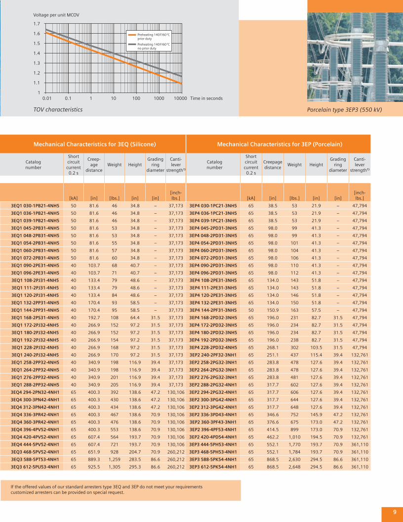
TOV characteristics
Time in seconds
Voltage per unit MCOV
Preheating 140 F/60 °Cprior duty
Preheating 140 F/60 °Cno prior duty
1.7
1.6
1.5
1.4
1.3
1.2
1.1
10.01 0.1 1 10 100 1000 10000
Mechanical Characteristics for 3EQ (Silicone) Mechanical Characteristics for 3EP (Porcelain)
Catalog number
Short circuit current
0.2 s
Creep-age
distanceWeight Height
Gradingring
diameter
Canti-lever
strength1)
Catalog number
Short circuit current
0.2 s
Creepagedistance
Weight HeightGrading
ring diameter
Canti-lever
strength1)
[kA] [in] [lbs.] [in] [in][inch-lbs.] [kA] [in] [lbs.] [in] [in]
[inch-lbs.]
3EQ1 030-1PB21-4NH5 50 81.6 46 34.8 – 37,173 3EP4 030-1PC21-3NH5 65 38.5 53 21.9 – 47,794
3EQ1 036-1PB21-4NH5 50 81.6 46 34.8 – 37,173 3EP4 036-1PC21-3NH5 65 38.5 53 21.9 – 47,794
3EQ1 039-1PB21-4NH5 50 81.6 46 34.8 – 37,173 3EP4 039-1PC21-3NH5 65 38.5 53 21.9 – 47,794
3EQ1 045-2PB31-4NH5 50 81.6 53 34.8 – 37,173 3EP4 045-2PD31-3NH5 65 98.0 99 41.3 – 47,794
3EQ1 048-2PB31-4NH5 50 81.6 53 34.8 – 37,173 3EP4 048-2PD31-3NH5 65 98.0 99 41.3 – 47,794
3EQ1 054-2PB31-4NH5 50 81.6 55 34.8 – 37,173 3EP4 054-2PD31-3NH5 65 98.0 101 41.3 – 47,794
3EQ1 060-2PB31-4NH5 50 81.6 57 34.8 – 37,173 3EP4 060-2PD31-3NH5 65 98.0 104 41.3 – 47,794
3EQ1 072-2PB31-4NH5 50 81.6 60 34.8 – 37,173 3EP4 072-2PD31-3NH5 65 98.0 106 41.3 – 47,794
3EQ1 090-2PE31-4NH5 40 103.7 68 40.7 – 37,173 3EP4 090-2PD31-3NH5 65 98.0 110 41.3 – 47,794
3EQ1 096-2PE31-4NH5 40 103.7 71 40.7 – 37,173 3EP4 096-2PD31-3NH5 65 98.0 112 41.3 – 47,794
3EQ1 108-2PJ31-4NH5 40 133.4 79 48.6 – 37,173 3EP4 108-2PE31-3NH5 65 134.0 143 51.8 – 47,794
3EQ1 111-2PJ31-4NH5 40 133.4 79 48.6 – 37,173 3EP4 111-2PE31-3NH5 65 134.0 143 51.8 – 47,794
3EQ1 120-2PJ31-4NH5 40 133.4 84 48.6 – 37,173 3EP4 120-2PE31-3NH5 65 134.0 146 51.8 – 47,794
3EQ1 132-2PP31-4NH5 40 170.4 93 58.5 – 37,173 3EP4 132-2PE31-3NH5 65 134.0 150 51.8 – 47,794
3EQ1 144-2PP31-4NH5 40 170.4 95 58.5 – 37,173 3EP4 144-2PF31-3NH5 50 150.9 163 57.5 – 47,794
3EQ1 168-2PS31-4NH5 40 192.7 108 64.4 31.5 37,173 3EP4 168-2PD32-3NH5 65 196.0 231 82.7 31.5 47,794
3EQ1 172-2PJ32-4NH5 40 266.9 152 97.2 31.5 37,173 3EP4 172-2PD32-3NH5 65 196.0 234 82.7 31.5 47,794
3EQ1 180-2PJ32-4NH5 40 266.9 152 97.2 31.5 37,173 3EP4 180-2PD32-3NH5 65 196.0 234 82.7 31.5 47,794
3EQ1 192-2PJ32-4NH5 40 266.9 154 97.2 31.5 37,173 3EP4 192-2PD32-3NH5 65 196.0 238 82.7 31.5 47,794
3EQ1 228-2PJ32-4NH5 40 266.9 168 97.2 31.5 37,173 3EP4 228-2PD32-4NH5 65 268.1 302 103.5 31.5 47,794
3EQ1 240-2PJ32-4NH5 40 266.9 170 97.2 31.5 37,173 3EP2 240-2PF32-3NH1 65 251.1 437 115.4 39.4 132,761
3EQ1 258-2PP32-4NH5 40 340.9 198 116.9 39.4 37,173 3EP2 258-2PG32-3NH1 65 283.8 478 127.6 39.4 132,761
3EQ1 264-2PP32-4NH5 40 340.9 198 116.9 39.4 37,173 3EP2 264-2PG32-3NH1 65 283.8 478 127.6 39.4 132,761
3EQ1 276-2PP32-4NH5 40 340.9 201 116.9 39.4 37,173 3EP2 276-2PG32-3NH1 65 283.8 481 127.6 39.4 132,761
3EQ1 288-2PP32-4NH5 40 340.9 205 116.9 39.4 37,173 3EP2 288-2PG32-4NH1 65 317.7 602 127.6 39.4 132,761
3EQ4 294-2PN32-4NH1 65 400.3 392 138.6 47.2 130,106 3EP2 294-2PG32-4NH1 65 317.7 606 127.6 39.4 132,761
3EQ4 300-3PN42-4NH1 65 400.3 430 138.6 47.2 130,106 3EP2 300-3PG42-4NH1 65 317.7 644 127.6 39.4 132,761
3EQ4 312-3PN42-4NH1 65 400.3 434 138.6 47.2 130,106 3EP2 312-3PG42-4NH1 65 317.7 648 127.6 39.4 132,761
3EQ4 336-3PR42-4NH1 65 400.3 467 138.6 70.9 130,106 3EP2 336-3PD43-4NH1 65 346.6 752 145.9 47.2 132,761
3EQ4 360-3PR42-4NH1 65 400.3 476 138.6 70.9 130,106 3EP2 360-3PF43-3NH1 65 376.6 675 173.0 47.2 132,761
3EQ4 396-4PV52-4NH1 65 400.3 553 138.6 70.9 130,106 3EP2 396-4PF53-4NH1 65 414.5 899 173.0 70.9 132,761
3EQ4 420-4PV52-4NH1 65 607.4 564 193.7 70.9 130,106 3EP2 420-4PD54-4NH1 65 462.2 1,010 194.5 70.9 132,761
3EQ4 444-5PV52-4NH1 65 607.4 721 193.7 70.9 130,106 3EP3 444-5PH53-4NH1 65 552.1 1,770 193.7 70.9 361,110
3EQ3 468-5PV52-4NH1 65 651.9 928 204.7 70.9 260,212 3EP3 468-5PH53-4NH1 65 552.1 1,784 193.7 70.9 361,110
3EQ3 588-5PT53-4NH1 65 889.3 1,259 283.5 86.6 260,212 3EP3 588-5PK54-4NH1 65 868.5 2,630 294.5 86.6 361,110
3EQ3 612-5PU53-4NH1 65 925.5 1,305 295.3 86.6 260,212 3EP3 612-5PK54-4NH1 65 868.5 2,648 294.5 86.6 361,110
9
If the offered values of our standard arresters type 3EQ and 3EP do not meet your requirements customized arresters can be provided on special request.
Porcelain type 3EP3 (550 kV)
10
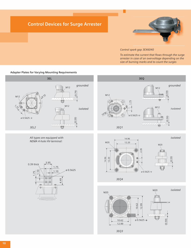
To estimate the current that fl ows through the surge arrester in case of an overvoltage depending on the size of burning marks and to count the surges
Control spark gap 3EX6040
Control Devices for Surge Arrester
3EQ3EL
Adapter Plates for Varying Mounting Requirements
(0.5
9)
M12
3EQ1
ø 0.56251.10
1.75
3.95
1.1
0
1.7
5
0.39 thick
4.4
9
(0.7
9)
M12
(0.5
9)
M12
(0.5
9)
M12
M20
10.62
(0.5
9)
12.99
10
.62
12
.99
ø 0.5625
M20
3EQ3
ø 0.5625
ø 10
1.75
M12
3EL2
isolated
grounded
1.7
5
M12
10"BCø 0.5625
isolated
grounded
14.96
12.20
12
.20
14
.96
2.3
6
ø 0.5625(0
.59
)
M20M20
3EQ4
isolated
isolated
All types are equipped with NEMA 4-hole HV-terminal:
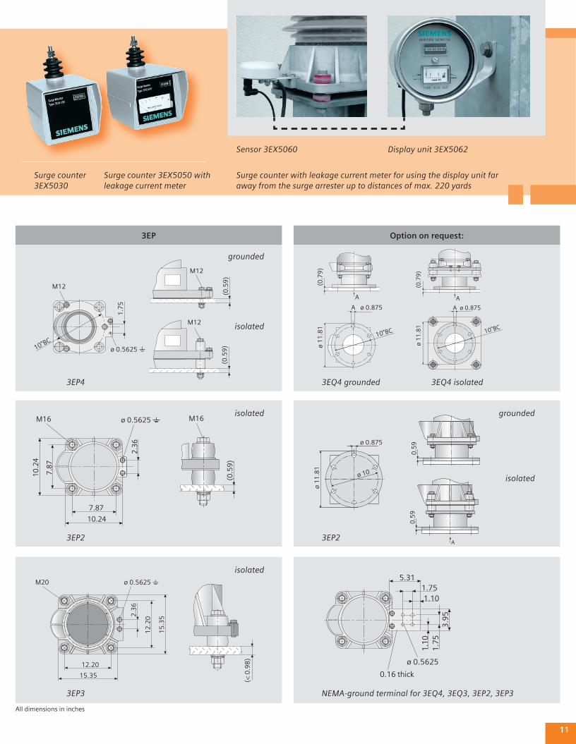
Surge counter 3EX5030
Surge counter 3EX5050 with leakage current meter
Surge counter with leakage current meter for using the display unit far away from the surge arrester up to distances of max. 220 yards
Sensor 3EX5060 Display unit 3EX5062
11
3EP Option on request:
(0.5
9)
M12
3EP4
ø 0.5625M16
(0.5
9)
2.36
7.87
10.24
7.87
10.2
4
M16
1.101.75
5.31
1.10
ø 0.5625
0.16 thick
1.7
53
.95
0.5
90
.59
A
M20 ø 0.5625
2.3
6
12
.20
15
.35
12.20
15.35
(< 0
.98
)
A
A
(0.7
9)
ø 1
1.8
1
ø 0.875
10"BC
(0.5
9)
M12
3EP2
NEMA-ground terminal for 3EQ4, 3EQ3, 3EP2, 3EP3
3EP2
isolated
3EP3
3EQ4 grounded
A
A
(0.7
9)
ø 1
1.8
1
ø 0.875
10"BC
grounded
ø 1
1.8
1
ø 0.875
ø 10
1.7
5
10"BCø 0.5625
M12
isolated
grounded
3EQ4 isolated
isolated
isolated
All dimensions in inches
This manual does not purport to cover all details or variations in equipment, nor to provide for every possible contingency to be met in connection with installation, operation or maintenance. Should fur-ther information be desired or should particular problems arise which are not covered suffi ciently for the purchaser’s purposes, the matter should be referred to the local Siemens’ sales offi ce. The contents of this manual shall not become part of or modify any prior or existing agreement, commit ment or relation-ship. The sales contract contains the entire obligation of Siemens. The warranty contained in the contract between the parties is the sole warranty of Siemens. Any statements continued herein do not create new warranties or modify the existing warranty.
Subject to change without prior notice
Order No. E50001-U113-A298-X-4APrinted in GermanyDispo 30000TH 263-040521 100930 PA 07042.
Phone (601) 932-98 28Fax (601) 932-99 11E-mail [email protected]
Please contact us at:
Siemens Power Transmission and Distribution Inc. Transmission Products DivisionDilip Biswas Manager-Market Development Arrester Products 444 Highway 49 S. Richland, MS 39218 Jackson, MS 39288-6289 Phone (601) 9 32-98 28 Cell (601) 9 40-04 22 Fax (601) 9 32-99 11 [email protected]
www.siemens.com/arrester