Embed Size (px)
Citation preview
3D Programming and ViewingWeek 3
David Breen
Department of Computer Science
Drexel University
Based on material from Ed Angel, University of New Mexico
CS 432/637INTERACTIVE COMPUTER GRAPHICS
3D Objects
Angel: Interactive Computer Graphics 3E © Addison-Wesley 2002
3
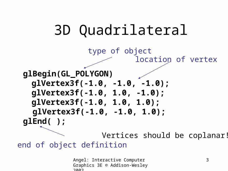
3D Quadrilateral
glBegin(GL_POLYGON)glVertex3f(-1.0, -1.0, -1.0);glVertex3f(-1.0, 1.0, -1.0);glVertex3f(-1.0, 1.0, 1.0);
glVertex3f(-1.0, -1.0, 1.0);glEnd( );
type of objectlocation of vertex
end of object definitionVertices should be coplanar!
Angel: Interactive Computer Graphics 3E © Addison-Wesley 2002
4
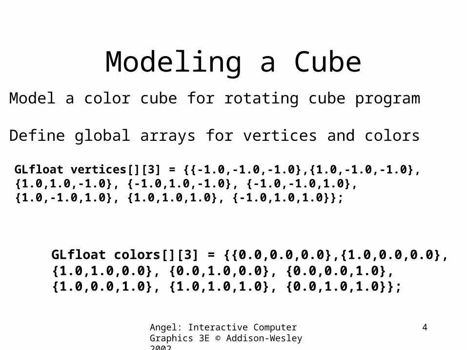
Modeling a Cube
GLfloat vertices[][3] = {{-1.0,-1.0,-1.0},{1.0,-1.0,-1.0},{1.0,1.0,-1.0}, {-1.0,1.0,-1.0}, {-1.0,-1.0,1.0},
{1.0,-1.0,1.0}, {1.0,1.0,1.0}, {-1.0,1.0,1.0}};
GLfloat colors[][3] = {{0.0,0.0,0.0},{1.0,0.0,0.0},{1.0,1.0,0.0}, {0.0,1.0,0.0}, {0.0,0.0,1.0},
{1.0,0.0,1.0}, {1.0,1.0,1.0}, {0.0,1.0,1.0}};
Model a color cube for rotating cube program
Define global arrays for vertices and colors
Angel: Interactive Computer Graphics 3E © Addison-Wesley 2002
5
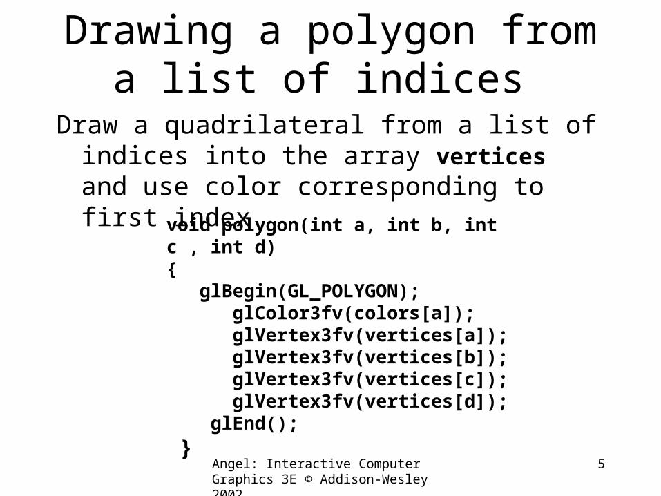
Drawing a polygon from a list of indices
Draw a quadrilateral from a list of indices into the array vertices and use color corresponding to first index
void polygon(int a, int b, int c , int d){ glBegin(GL_POLYGON); glColor3fv(colors[a]); glVertex3fv(vertices[a]); glVertex3fv(vertices[b]); glVertex3fv(vertices[c]); glVertex3fv(vertices[d]); glEnd(); }
Angel: Interactive Computer Graphics 3E © Addison-Wesley 2002
6
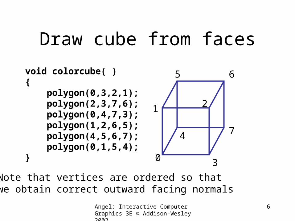
Draw cube from faces
void colorcube( ){ polygon(0,3,2,1); polygon(2,3,7,6); polygon(0,4,7,3); polygon(1,2,6,5); polygon(4,5,6,7); polygon(0,1,5,4);} 0
5 6
2
4 7
1
3
Note that vertices are ordered so that we obtain correct outward facing normals
Angel: Interactive Computer Graphics 3E © Addison-Wesley 2002
7
Efficiency
• The weakness of our approach is that we are building the model in the application and must do many function calls to draw the cube
• Drawing a cube by its faces in the most straight forward way requires
–6 glBegin, 6 glEnd–6 glColor–24 glVertex–More if we use texture and lighting
Angel: Interactive Computer Graphics 3E © Addison-Wesley 2002
8
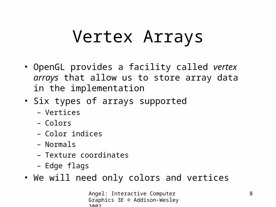
Vertex Arrays
• OpenGL provides a facility called vertex arrays that allow us to store array data in the implementation
• Six types of arrays supported– Vertices– Colors– Color indices– Normals– Texture coordinates– Edge flags
• We will need only colors and vertices
Angel: Interactive Computer Graphics 3E © Addison-Wesley 2002
9
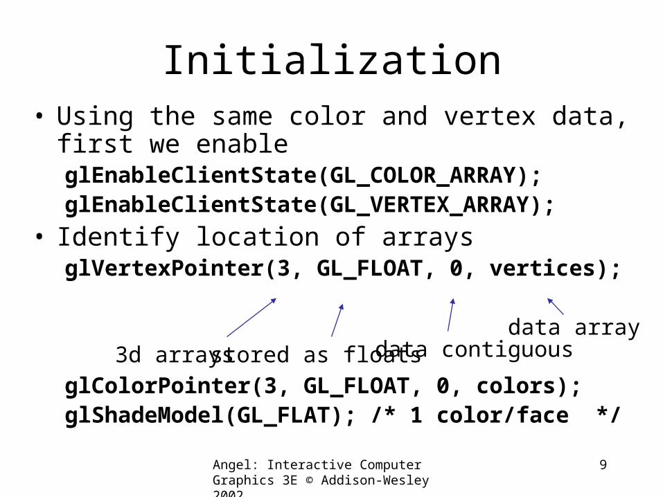
Initialization• Using the same color and vertex data, first we
enableglEnableClientState(GL_COLOR_ARRAY);glEnableClientState(GL_VERTEX_ARRAY);
• Identify location of arraysglVertexPointer(3, GL_FLOAT, 0, vertices);
glColorPointer(3, GL_FLOAT, 0, colors);glShadeModel(GL_FLAT); /* 1 color/face */
3d arrays stored as floats data contiguousdata array
Angel: Interactive Computer Graphics 3E © Addison-Wesley 2002
10
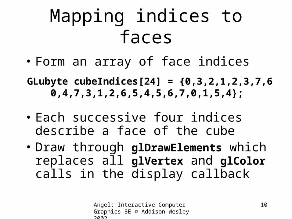
Mapping indices to faces
• Form an array of face indices
• Each successive four indices describe a face of the cube
• Draw through glDrawElements which replaces all glVertex and glColor calls in the display callback
GLubyte cubeIndices[24] = {0,3,2,1,2,3,7,6 0,4,7,3,1,2,6,5,4,5,6,7,0,1,5,4};
Angel: Interactive Computer Graphics 3E © Addison-Wesley 2002
11
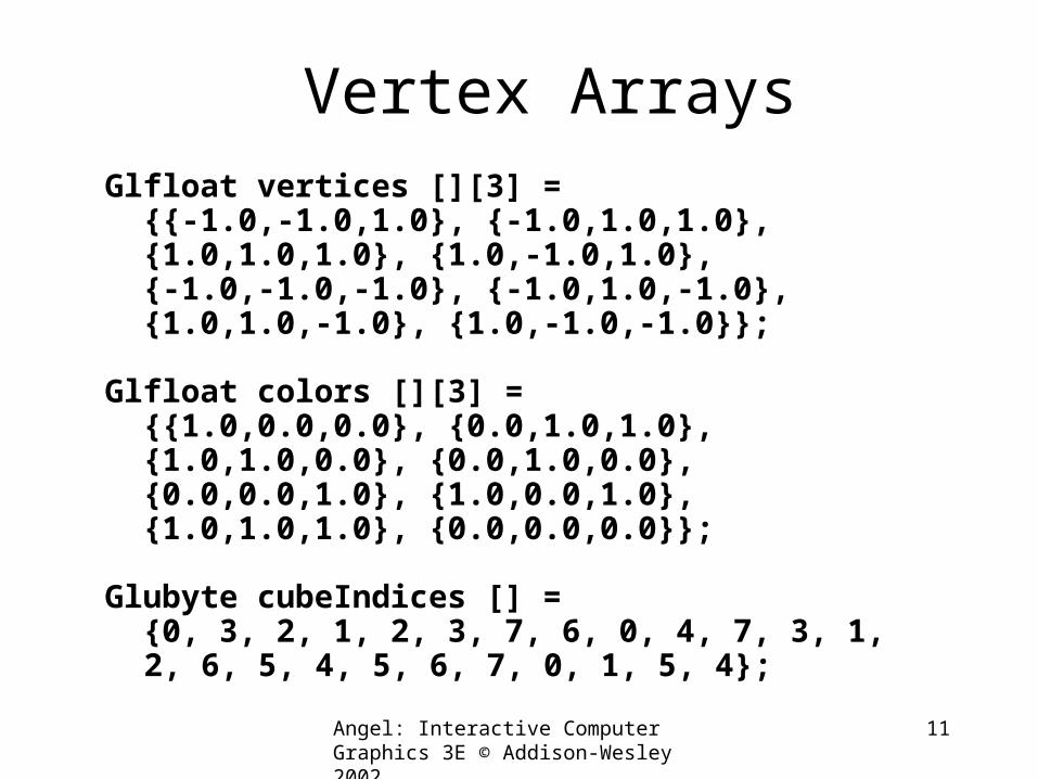
Vertex ArraysGlfloat vertices [][3] = {{-1.0,-1.0,1.0}, {-1.0,1.0,1.0}, {1.0,1.0,1.0}, {1.0,-1.0,1.0}, {-1.0,-1.0,-1.0}, {-1.0,1.0,-1.0}, {1.0,1.0,-1.0}, {1.0,-1.0,-1.0}};
Glfloat colors [][3] = {{1.0,0.0,0.0}, {0.0,1.0,1.0}, {1.0,1.0,0.0}, {0.0,1.0,0.0}, {0.0,0.0,1.0}, {1.0,0.0,1.0}, {1.0,1.0,1.0}, {0.0,0.0,0.0}};
Glubyte cubeIndices [] = {0, 3, 2, 1, 2, 3, 7, 6, 0, 4, 7, 3, 1,
2, 6, 5, 4, 5, 6, 7, 0, 1, 5, 4};
Angel: Interactive Computer Graphics 3E © Addison-Wesley 2002
12
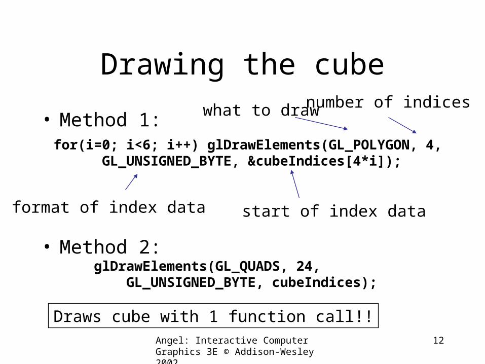
Drawing the cube
• Method 1:
• Method 2:
for(i=0; i<6; i++) glDrawElements(GL_POLYGON, 4, GL_UNSIGNED_BYTE, &cubeIndices[4*i]);
format of index data start of index data
what to draw number of indices
glDrawElements(GL_QUADS, 24, GL_UNSIGNED_BYTE, cubeIndices);
Draws cube with 1 function call!!
Angel: Interactive Computer Graphics 3E © Addison-Wesley 2002
13
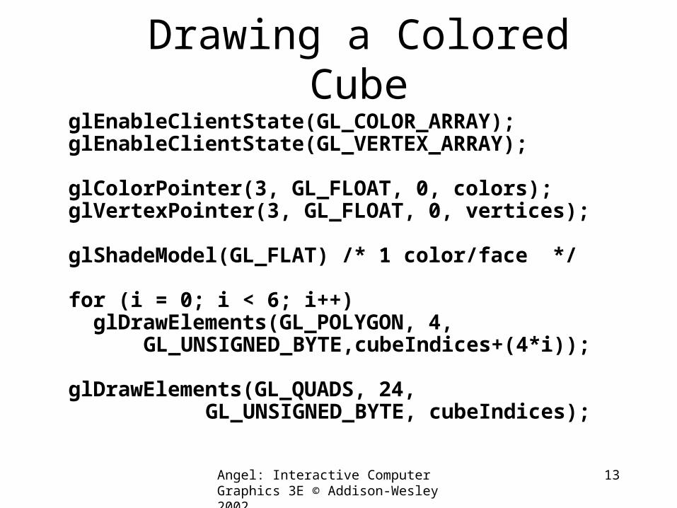
Drawing a Colored CubeglEnableClientState(GL_COLOR_ARRAY);glEnableClientState(GL_VERTEX_ARRAY);
glColorPointer(3, GL_FLOAT, 0, colors);glVertexPointer(3, GL_FLOAT, 0, vertices); glShadeModel(GL_FLAT) /* 1 color/face */
for (i = 0; i < 6; i++) glDrawElements(GL_POLYGON, 4,
GL_UNSIGNED_BYTE,cubeIndices+(4*i));
glDrawElements(GL_QUADS, 24, GL_UNSIGNED_BYTE, cubeIndices);
Display Lists
Angel: Interactive Computer Graphics 3E © Addison-Wesley 2002
15
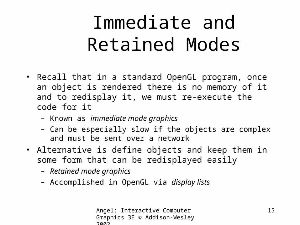
Immediate and Retained Modes
• Recall that in a standard OpenGL program, once an object is rendered there is no memory of it and to redisplay it, we must re-execute the code for it– Known as immediate mode graphics
– Can be especially slow if the objects are complex and must be sent over a network
• Alternative is define objects and keep them in some form that can be redisplayed easily– Retained mode graphics
– Accomplished in OpenGL via display lists
Angel: Interactive Computer Graphics 3E © Addison-Wesley 2002
16
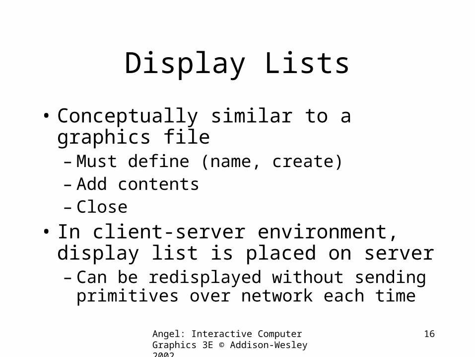
Display Lists
• Conceptually similar to a graphics file– Must define (name, create)– Add contents– Close
• In client-server environment, display list is placed on server– Can be redisplayed without sending
primitives over network each time
Angel: Interactive Computer Graphics 3E © Addison-Wesley 2002
17
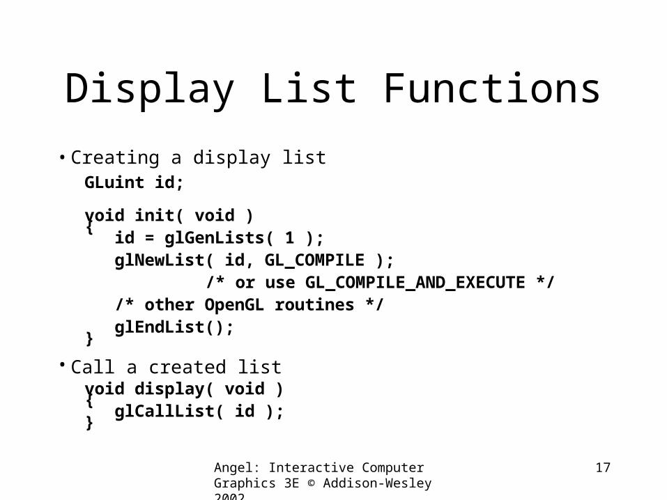
Display List Functions
• Creating a display listGLuint id;
void init( void ){ id = glGenLists( 1 ); glNewList( id, GL_COMPILE ); /* or use GL_COMPILE_AND_EXECUTE */ /* other OpenGL routines */ glEndList();}
• Call a created listvoid display( void ){ glCallList( id );}
Angel: Interactive Computer Graphics 3E © Addison-Wesley 2002
18
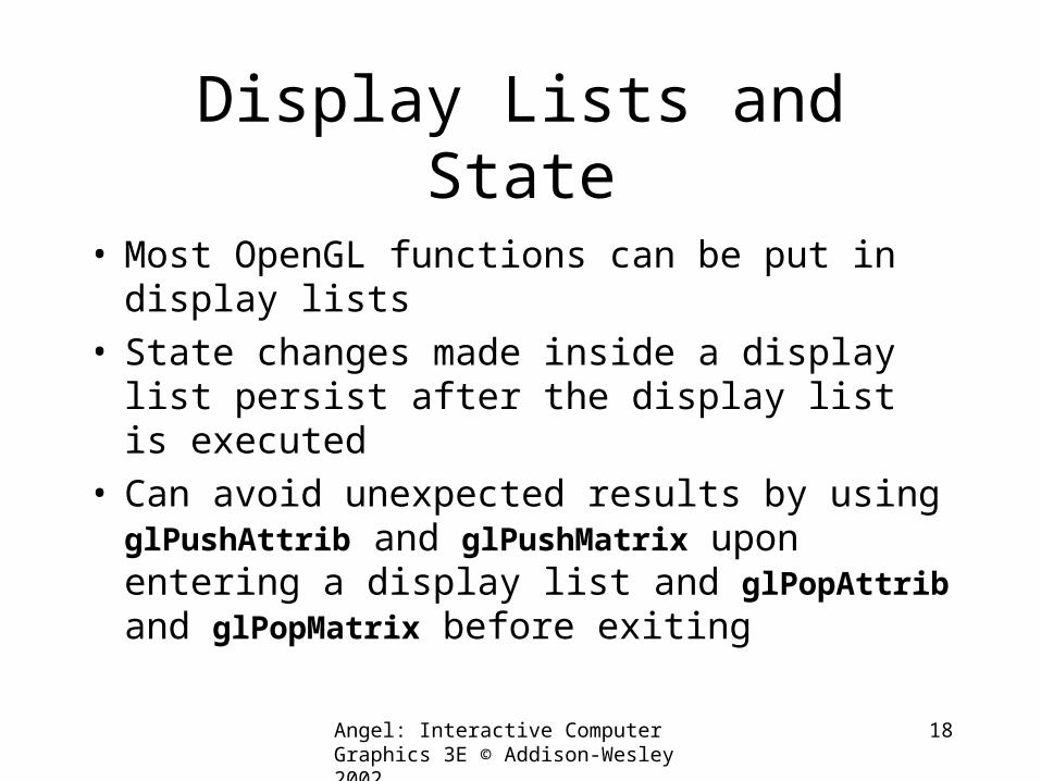
Display Lists and State
• Most OpenGL functions can be put in display lists
• State changes made inside a display list persist after the display list is executed
• Can avoid unexpected results by using glPushAttrib and glPushMatrix upon entering a display list and glPopAttrib and glPopMatrix before exiting
Angel: Interactive Computer Graphics 3E © Addison-Wesley 2002
19
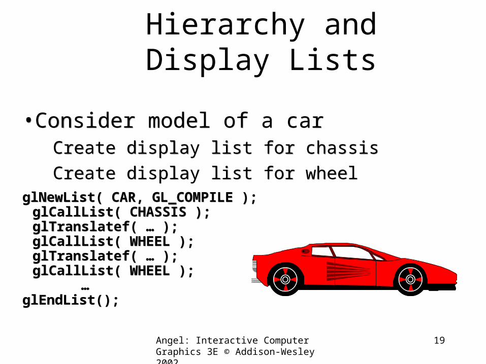
Hierarchy and Display Lists
•Consider model of a car Create display list for chassis Create display list for wheel
glNewList( CAR, GL_COMPILE );glCallList( CHASSIS );glTranslatef( … );glCallList( WHEEL );glTranslatef( … );glCallList( WHEEL );
…glEndList();
•Consider model of a car Create display list for chassis Create display list for wheel
glNewList( CAR, GL_COMPILE );glCallList( CHASSIS );glTranslatef( … );glCallList( WHEEL );glTranslatef( … );glCallList( WHEEL );
…glEndList();
Angel: Interactive Computer Graphics 3E © Addison-Wesley 2002
20
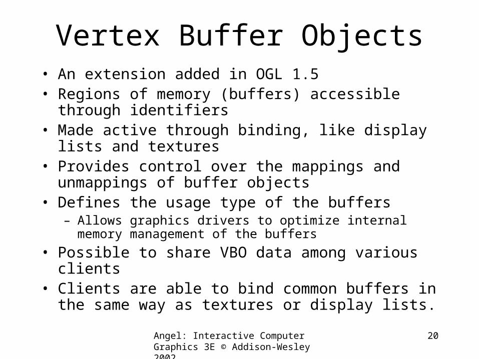
Vertex Buffer Objects• An extension added in OGL 1.5• Regions of memory (buffers) accessible through
identifiers• Made active through binding, like display lists and
textures• Provides control over the mappings and unmappings
of buffer objects• Defines the usage type of the buffers
– Allows graphics drivers to optimize internal memory management of the buffers
• Possible to share VBO data among various clients• Clients are able to bind common buffers in the same
way as textures or display lists.
GLU and GLUT Objects
Angel: Interactive Computer Graphics 3E © Addison-Wesley 2002
23
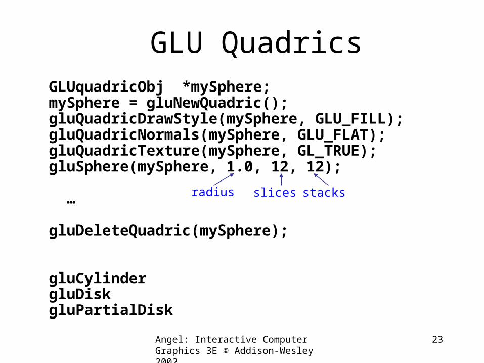
GLU QuadricsGLUquadricObj *mySphere;mySphere = gluNewQuadric();gluQuadricDrawStyle(mySphere, GLU_FILL);gluQuadricNormals(mySphere, GLU_FLAT);gluQuadricTexture(mySphere, GL_TRUE);gluSphere(mySphere, 1.0, 12, 12);
…
gluDeleteQuadric(mySphere);
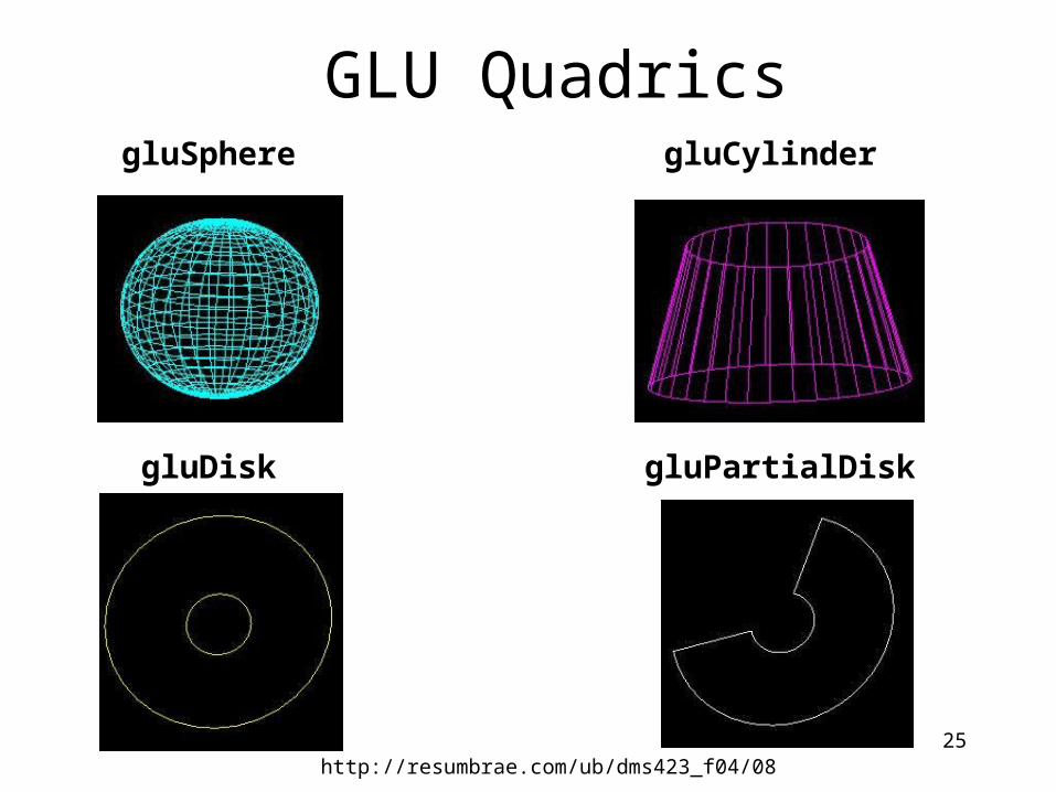
gluCylindergluDiskgluPartialDisk
radius slices stacks
Angel: Interactive Computer Graphics 3E © Addison-Wesley 2002
24
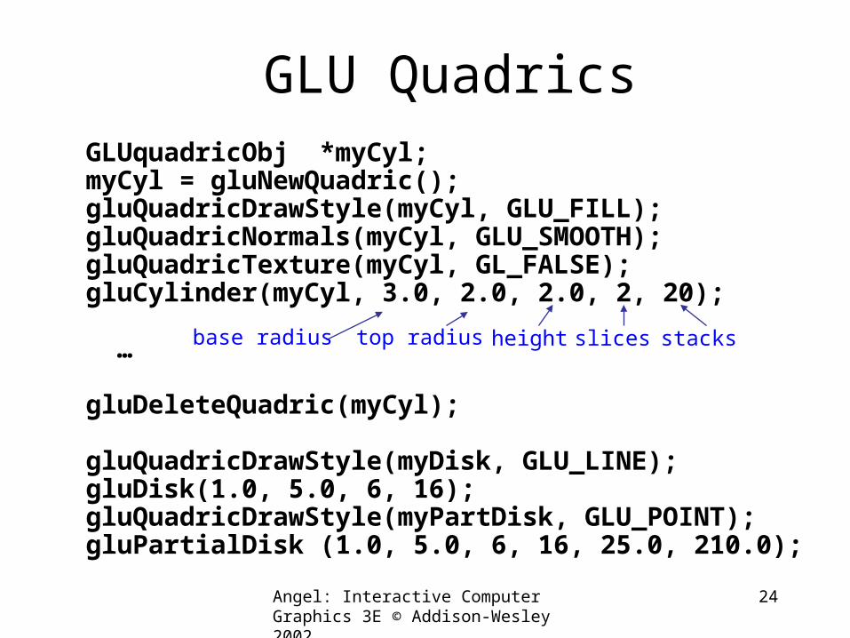
GLU QuadricsGLUquadricObj *myCyl;myCyl = gluNewQuadric();gluQuadricDrawStyle(myCyl, GLU_FILL);gluQuadricNormals(myCyl, GLU_SMOOTH);gluQuadricTexture(myCyl, GL_FALSE);gluCylinder(myCyl, 3.0, 2.0, 2.0, 2, 20);
…
gluDeleteQuadric(myCyl);
gluQuadricDrawStyle(myDisk, GLU_LINE);gluDisk(1.0, 5.0, 6, 16);gluQuadricDrawStyle(myPartDisk, GLU_POINT);gluPartialDisk (1.0, 5.0, 6, 16, 25.0, 210.0);
base radius top radius height slices stacks
Angel: Interactive Computer Graphics 3E © Addison-Wesley 2002
25
GLU Quadrics gluSphere gluCylinder
gluDisk gluPartialDisk
http://resumbrae.com/ub/dms423_f04/08
Angel: Interactive Computer Graphics 3E © Addison-Wesley 2002
26
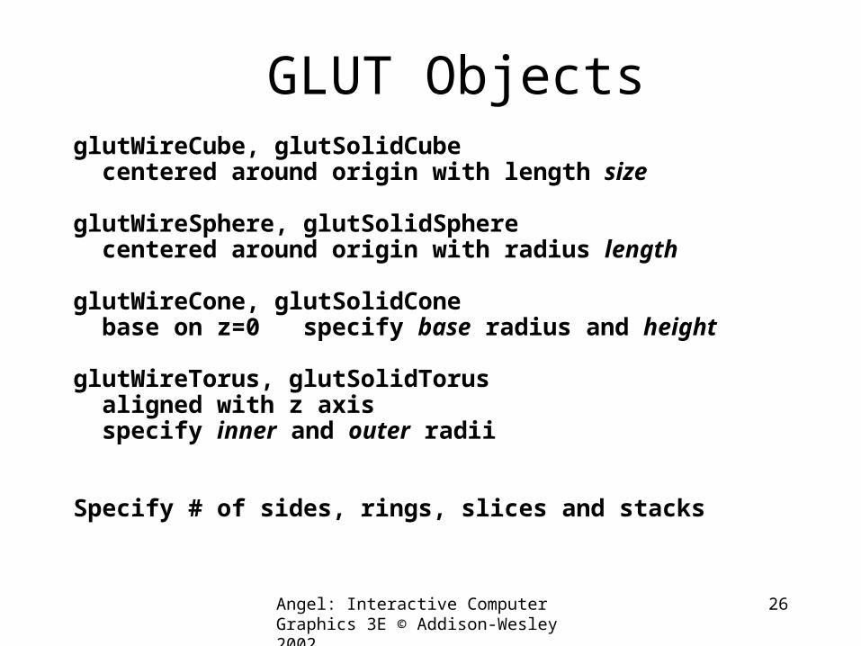
GLUT ObjectsglutWireCube, glutSolidCube centered around origin with length size
glutWireSphere, glutSolidSphere centered around origin with radius length
glutWireCone, glutSolidCone base on z=0 specify base radius and height
glutWireTorus, glutSolidTorus aligned with z axis specify inner and outer radii
Specify # of sides, rings, slices and stacks
Angel: Interactive Computer Graphics 3E © Addison-Wesley 2002
27
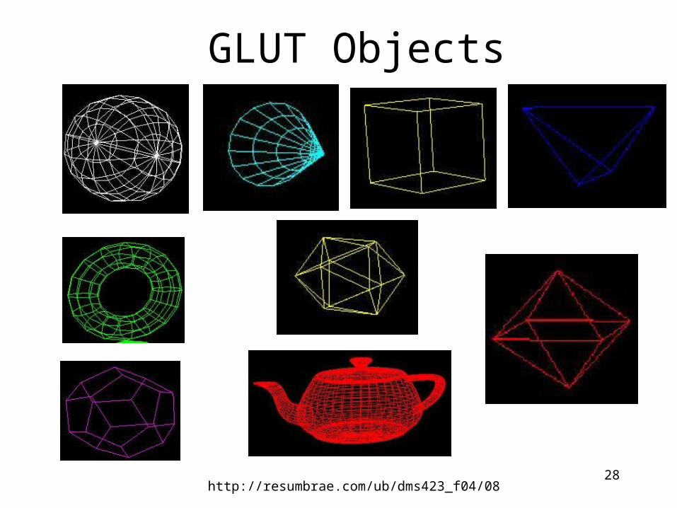
GLUT ObjectsglutWireTetrahedron, glutSolidTetrahedron
glutWireOctahedron, glutSolidOctahedron
glutWireDodecahedron, glutSolidDodecahedron
glutWireIcosahedron, glutSolidIcosahedron
Generate Platonic solids with all vertices on unit sphere
glutWireTeapot, glutSolidTeapot size may be adjusted
Angel: Interactive Computer Graphics 3E © Addison-Wesley 2002
28
GLUT Objects
http://resumbrae.com/ub/dms423_f04/08
Viewing Overview
Angel: Interactive Computer Graphics 3E © Addison-Wesley 2002
30
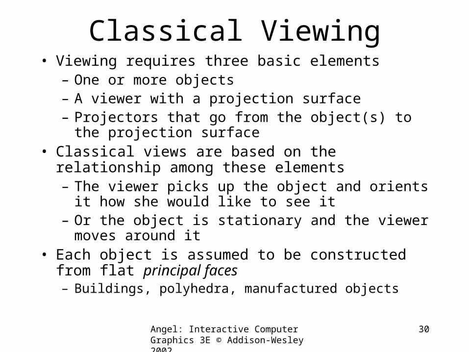
Classical Viewing• Viewing requires three basic elements
– One or more objects– A viewer with a projection surface– Projectors that go from the object(s) to the projection
surface• Classical views are based on the relationship among
these elements– The viewer picks up the object and orients it how she
would like to see it– Or the object is stationary and the viewer moves
around it• Each object is assumed to be constructed from flat
principal faces – Buildings, polyhedra, manufactured objects
Angel: Interactive Computer Graphics 3E © Addison-Wesley 2002
31
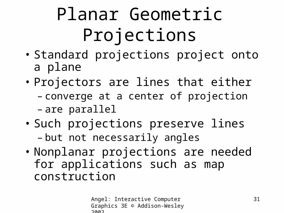
Planar Geometric Projections
• Standard projections project onto a plane
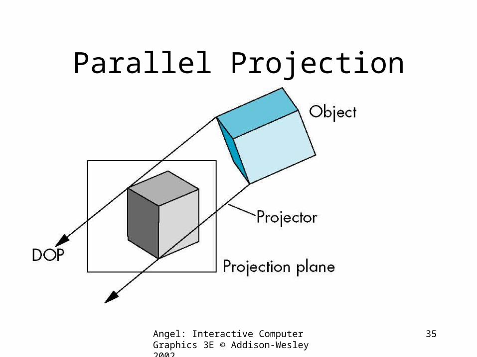
• Projectors are lines that either– converge at a center of projection– are parallel
• Such projections preserve lines– but not necessarily angles
• Nonplanar projections are needed for applications such as map construction
Angel: Interactive Computer Graphics 3E © Addison-Wesley 2002
32
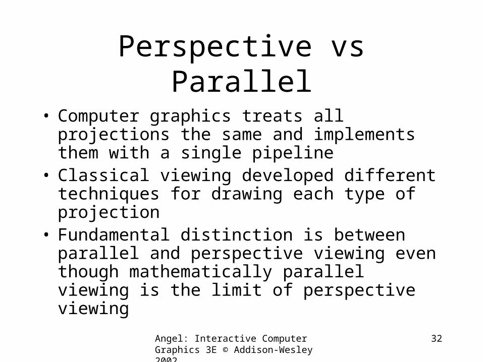
Perspective vs Parallel
• Computer graphics treats all projections the same and implements them with a single pipeline
• Classical viewing developed different techniques for drawing each type of projection
• Fundamental distinction is between parallel and perspective viewing even though mathematically parallel viewing is the limit of perspective viewing
Angel: Interactive Computer Graphics 3E © Addison-Wesley 2002
33
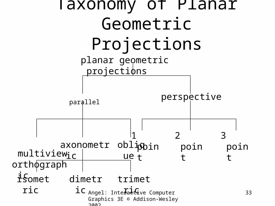
Taxonomy of Planar Geometric Projections
parallelperspective
axonometric multivieworthographic
oblique
isometric dimetric trimetric
2 point1 point 3 point
planar geometric projections
Angel: Interactive Computer Graphics 3E © Addison-Wesley 2002
34
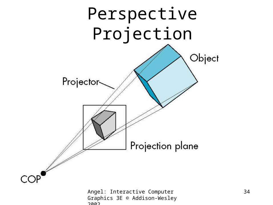
Perspective Projection
Angel: Interactive Computer Graphics 3E © Addison-Wesley 2002
35
Parallel Projection
Angel: Interactive Computer Graphics 3E © Addison-Wesley 2002
36
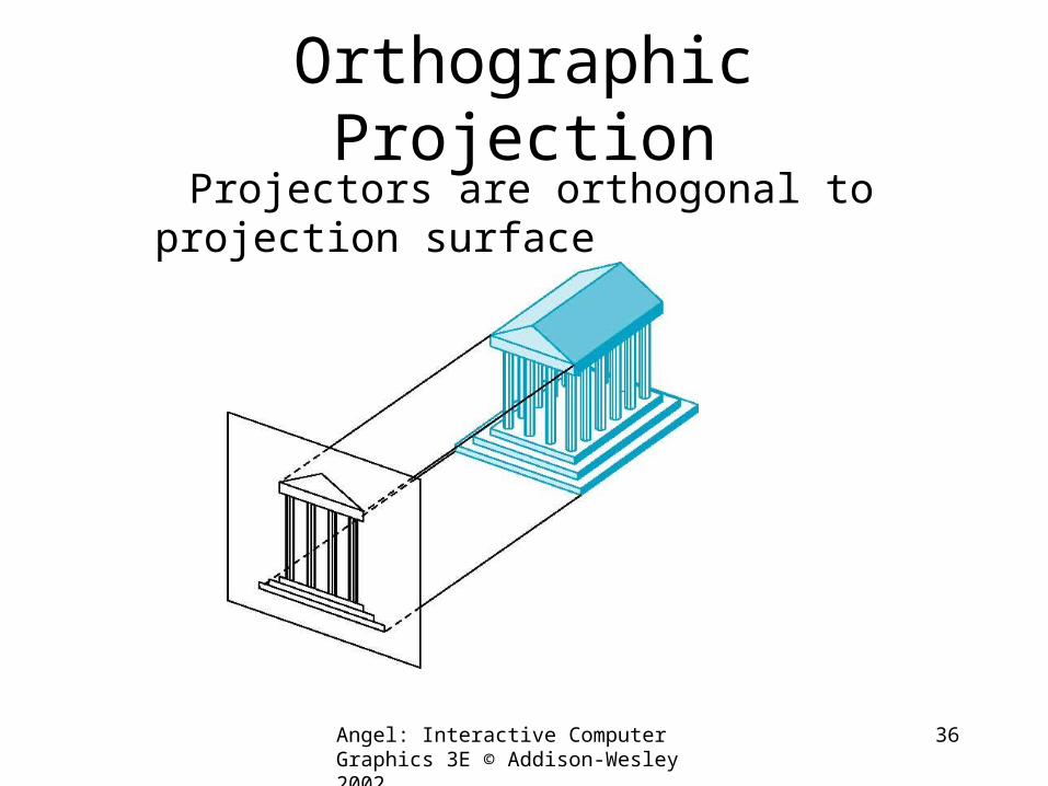
Orthographic Projection Projectors are orthogonal to projection
surface
Angel: Interactive Computer Graphics 3E © Addison-Wesley 2002
37
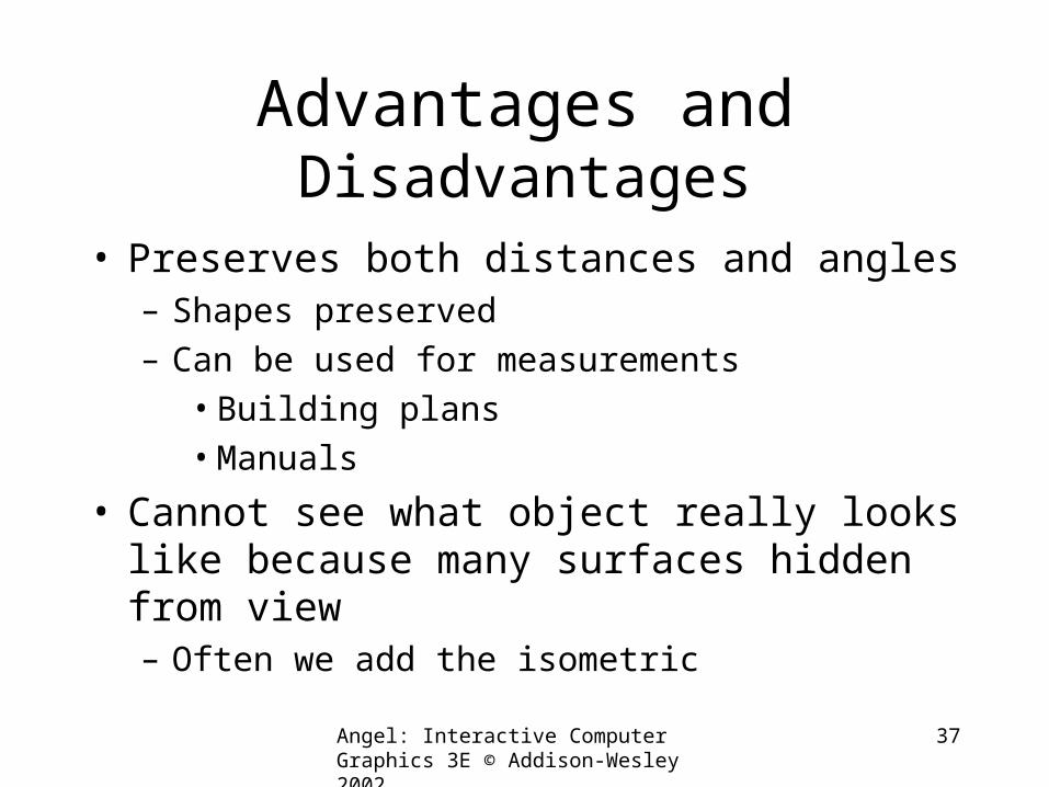
Advantages and Disadvantages
• Preserves both distances and angles– Shapes preserved– Can be used for measurements
• Building plans• Manuals
• Cannot see what object really looks like because many surfaces hidden from view– Often we add the isometric
Angel: Interactive Computer Graphics 3E © Addison-Wesley 2002
38
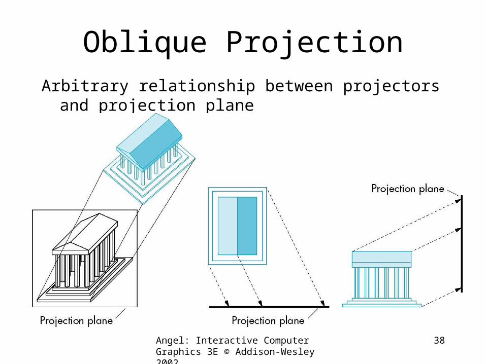
Oblique ProjectionArbitrary relationship between projectors and projection
plane
Angel: Interactive Computer Graphics 3E © Addison-Wesley 2002
39
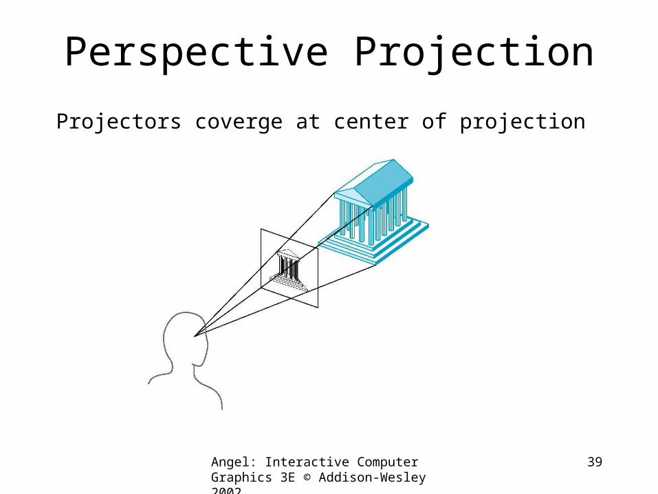
Perspective Projection
Projectors coverge at center of projection
Angel: Interactive Computer Graphics 3E © Addison-Wesley 2002
40
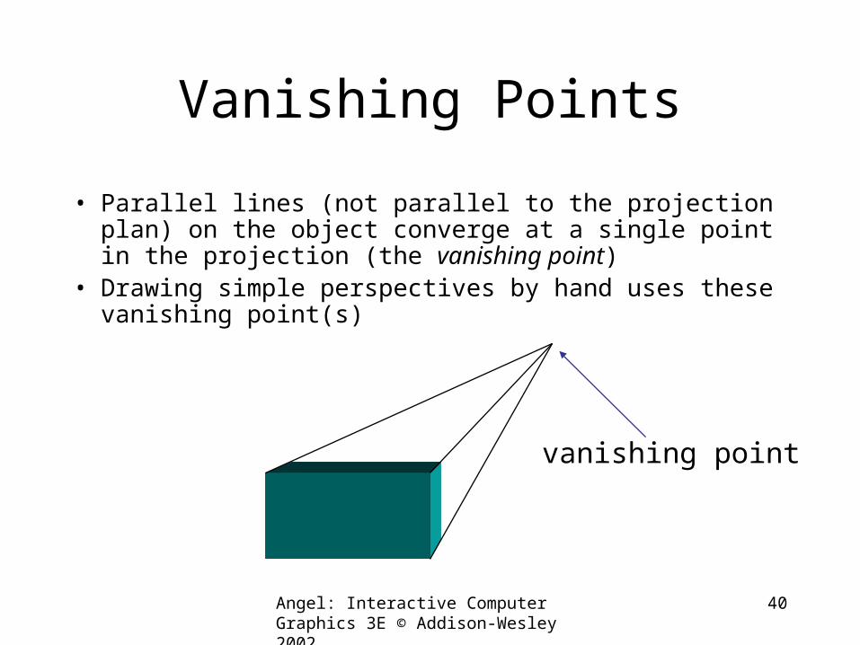
Vanishing Points
• Parallel lines (not parallel to the projection plan) on the object converge at a single point in the projection (the vanishing point)
• Drawing simple perspectives by hand uses these vanishing point(s)
vanishing point
Angel: Interactive Computer Graphics 3E © Addison-Wesley 2002
41
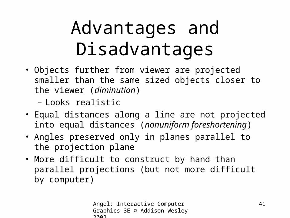
Advantages and Disadvantages
• Objects further from viewer are projected smaller than the same sized objects closer to the viewer (diminution)– Looks realistic
• Equal distances along a line are not projected into equal distances (nonuniform foreshortening)
• Angles preserved only in planes parallel to the projection plane
• More difficult to construct by hand than parallel projections (but not more difficult by computer)
Computer Viewing
Angel: Interactive Computer Graphics 3E © Addison-Wesley 2002
43
Objectives
• Introduce OpenGL viewing functions
• Look at alternate viewing APIs
Angel: Interactive Computer Graphics 3E © Addison-Wesley 2002
44
Computer Viewing
• There are three aspects of the viewing process, all of which are implemented in the pipeline,– Positioning the camera
• Setting the model-view matrix– Selecting a lens
• Setting the projection matrix– Clipping
• Setting the view volume
Angel: Interactive Computer Graphics 3E © Addison-Wesley 2002
45
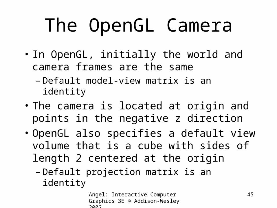
The OpenGL Camera
• In OpenGL, initially the world and camera frames are the same– Default model-view matrix is an identity
• The camera is located at origin and points in the negative z direction
• OpenGL also specifies a default view volume that is a cube with sides of length 2 centered at the origin– Default projection matrix is an identity
Angel: Interactive Computer Graphics 3E © Addison-Wesley 2002
46
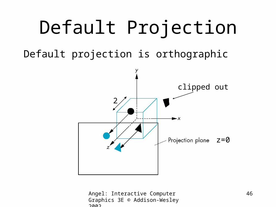
Default Projection
Default projection is orthographic
clipped out
z=0
2
Angel: Interactive Computer Graphics 3E © Addison-Wesley 2002
47
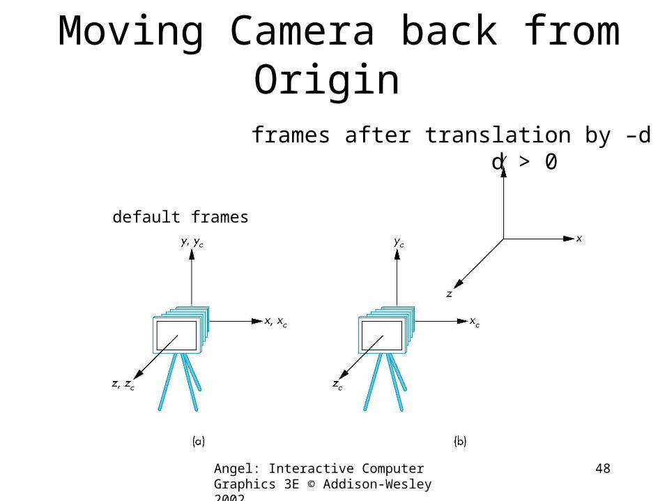
Moving the Camera Frame
• If we want to visualize an object with both positive and negative z values we can either– Move the camera in the positive z direction
• Translate the camera frame– Move the objects in the negative z direction
• Translate the world frame
• Both of these views are equivalent and are determined by the model-view matrix– Want a translation (glTranslatef(0.0,0.0,-d);)– d > 0
Angel: Interactive Computer Graphics 3E © Addison-Wesley 2002
48
Moving Camera back from Origin
default frames
frames after translation by –d d > 0
Angel: Interactive Computer Graphics 3E © Addison-Wesley 2002
49
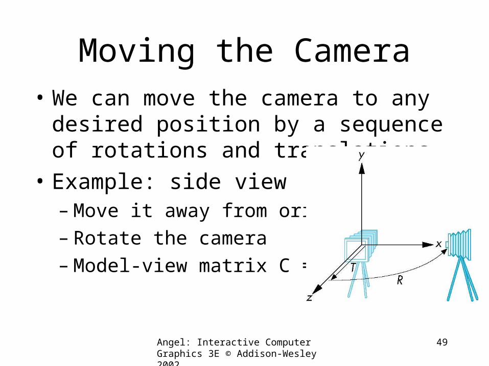
Moving the Camera• We can move the camera to any desired
position by a sequence of rotations and translations
• Example: side view– Move it away from origin– Rotate the camera– Model-view matrix C = TR
Angel: Interactive Computer Graphics 3E © Addison-Wesley 2002
50
The LookAt Function• The GLU library contains the function gluLookAt to
form the required modelview matrix through a simple interface
• Note the need for setting an up direction• Still need to initialize
– Can concatenate with modeling transformations• Example: isometric view of cube aligned with axes
glMatrixMode(GL_MODELVIEW):glLoadIdentity();gluLookAt(1.0, 1.0, 1.0, 0.0, 0.0, 0.0, 0., 1.0. 0.0);
Angel: Interactive Computer Graphics 3E © Addison-Wesley 2002
51
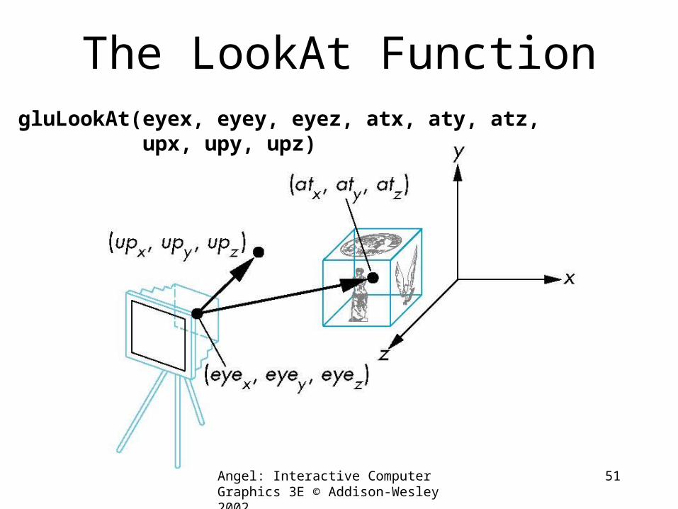
The LookAt FunctiongluLookAt(eyex, eyey, eyez, atx, aty, atz, upx, upy, upz)
Angel: Interactive Computer Graphics 3E © Addison-Wesley 2002
52
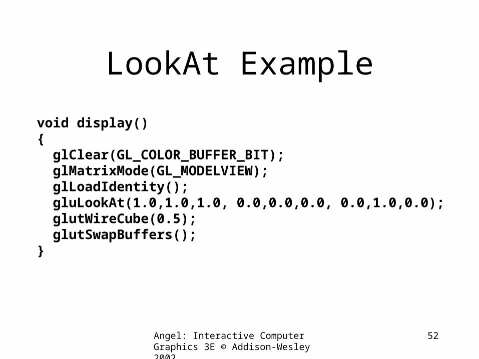
LookAt Example
void display(){ glClear(GL_COLOR_BUFFER_BIT); glMatrixMode(GL_MODELVIEW); glLoadIdentity(); gluLookAt(1.0,1.0,1.0, 0.0,0.0,0.0, 0.0,1.0,0.0); glutWireCube(0.5); glutSwapBuffers();}
Angel: Interactive Computer Graphics 3E © Addison-Wesley 2002
53
Other Viewing APIs
• The LookAt function is only one possible API for positioning the camera
• Others include– View reference point, view plane normal,
view up (PHIGS, GKS-3D)– Yaw, pitch, roll– Elevation, azimuth, twist– Direction angles
Angel: Interactive Computer Graphics 3E © Addison-Wesley 2002
54
Projections and Normalization
• The default projection in the eye (camera) frame is orthographic
• For points within the default view volume
• Most graphics systems use view normalization– All other views are converted to the default view by
transformations that determine the projection matrix– Allows use of the same pipeline for all views
xp = xyp = yzp = 0
Angel: Interactive Computer Graphics 3E © Addison-Wesley 2002
55
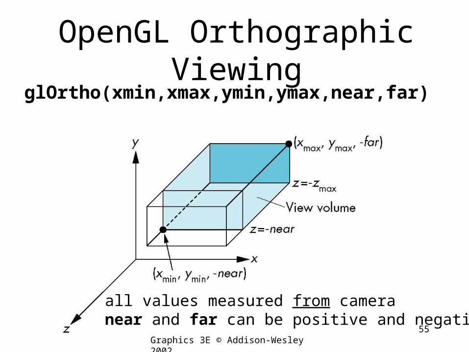
OpenGL Orthographic ViewingglOrtho(xmin,xmax,ymin,ymax,near,far)
all values measured from cameranear and far can be positive and negative
Angel: Interactive Computer Graphics 3E © Addison-Wesley 2002
56
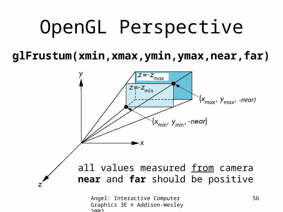
OpenGL PerspectiveglFrustum(xmin,xmax,ymin,ymax,near,far)
-near)
all values measured from cameranear and far should be positive
Angel: Interactive Computer Graphics 3E © Addison-Wesley 2002
57
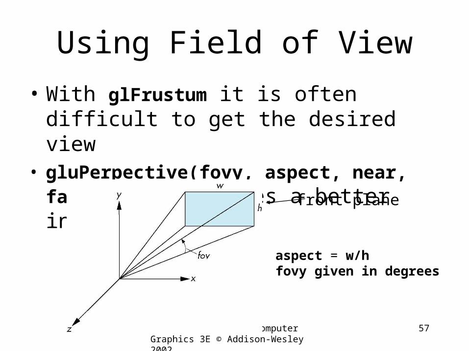
Using Field of View
• With glFrustum it is often difficult to get the desired view
• gluPerpective(fovy, aspect, near, far) often provides a better interface
aspect = w/hfovy given in degrees
front plane
Angel: Interactive Computer Graphics 3E © Addison-Wesley 2002
58
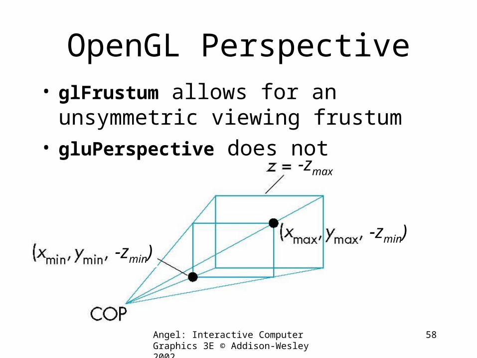
OpenGL Perspective
-zmax
-zmin)-zmin)
• glFrustum allows for an unsymmetric viewing frustum
• gluPerspective does not
Angel: Interactive Computer Graphics 3E © Addison-Wesley 2002
59
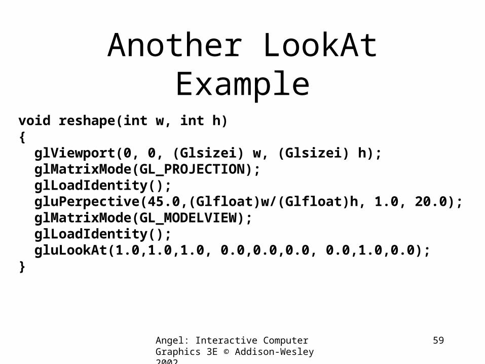
Another LookAt Example
void reshape(int w, int h){ glViewport(0, 0, (Glsizei) w, (Glsizei) h); glMatrixMode(GL_PROJECTION); glLoadIdentity(); gluPerpective(45.0,(Glfloat)w/(Glfloat)h, 1.0, 20.0); glMatrixMode(GL_MODELVIEW); glLoadIdentity(); gluLookAt(1.0,1.0,1.0, 0.0,0.0,0.0, 0.0,1.0,0.0);}
Angel: Interactive Computer Graphics 3E © Addison-Wesley 2002
60
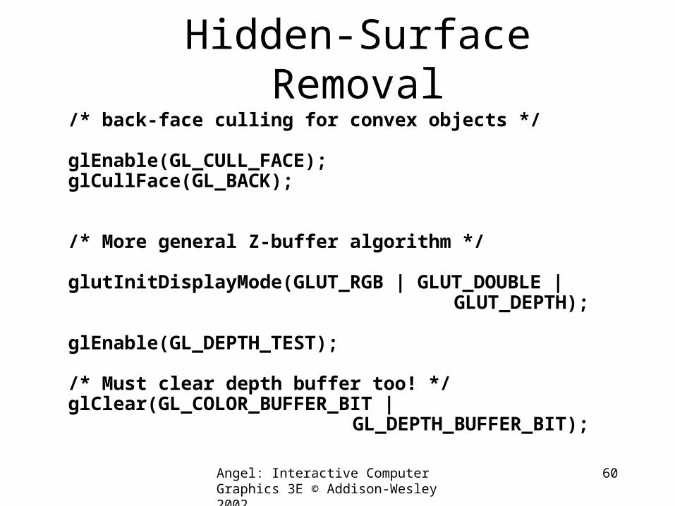
Hidden-Surface Removal/* back-face culling for convex objects */
glEnable(GL_CULL_FACE);glCullFace(GL_BACK);
/* More general Z-buffer algorithm */
glutInitDisplayMode(GLUT_RGB | GLUT_DOUBLE | GLUT_DEPTH);
glEnable(GL_DEPTH_TEST);
/* Must clear depth buffer too! */glClear(GL_COLOR_BUFFER_BIT |
GL_DEPTH_BUFFER_BIT);