Embed Size (px)
Citation preview
Lec 2 Systems Architecture II 1
Systems Architecture II
TopicsOverview of Pipelining*
Pipelined Datapath and Control*
Notes Courtesy of Jeremy R. Johnson
*This lecture was derived from material in the text (Chap. 6).
Notes Courtesy of Jeremy R. Johnson
Lec 2 Systems Architecture II 2
Systems Architecture II
Topic 1: Overview of Pipelining
Lec 2 Systems Architecture II 3
Introduction• Objective: To understand pipelining and the enhanced
performance it provides
• Pipelining is an implementation technique in which multiple instructions are overlapped in execution. Instructions are broken down into stages and while one instruction is executing one stage another instruction can simultaneously execute another stage.
• Topics– Introduction to pipelining– Speedup– Designing instruction sets for pipelining– Pipelining hazards– Superscalar and dynamic pipelining
Lec 2 Systems Architecture II 4
A Simple Example
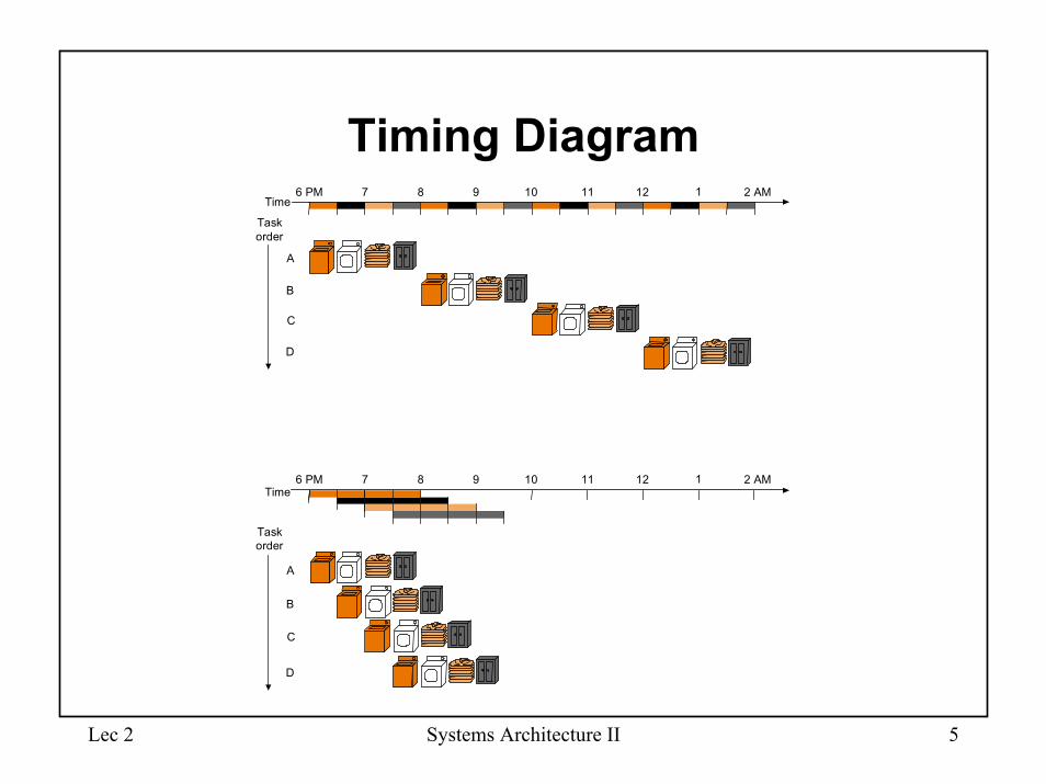
• Stages in laundry example– wash clothes– dry clothes– fold clothes– put clothes away
• Same time to complete single load• Speedup requires multiple loads
– While drying the first load, one can begin washing the second load– When the first load is being folded the second load can be dried while
a third load begins– When the clothes from the first load are being put away four loads are
operating simultaneously– With sufficiently many loads the time is reduced by a factor of 4
Lec 2 Systems Architecture II 5
Timing DiagramTime
76 PM 8 9 10 11 12 1 2 AM
A
B
C
D
Time76 PM 8 9 10 11 12 1 2 AM
A
B
C
D
Task�order
Task�order
Lec 2 Systems Architecture II 6
Pipeline Stages for MIPS Instruction Execution
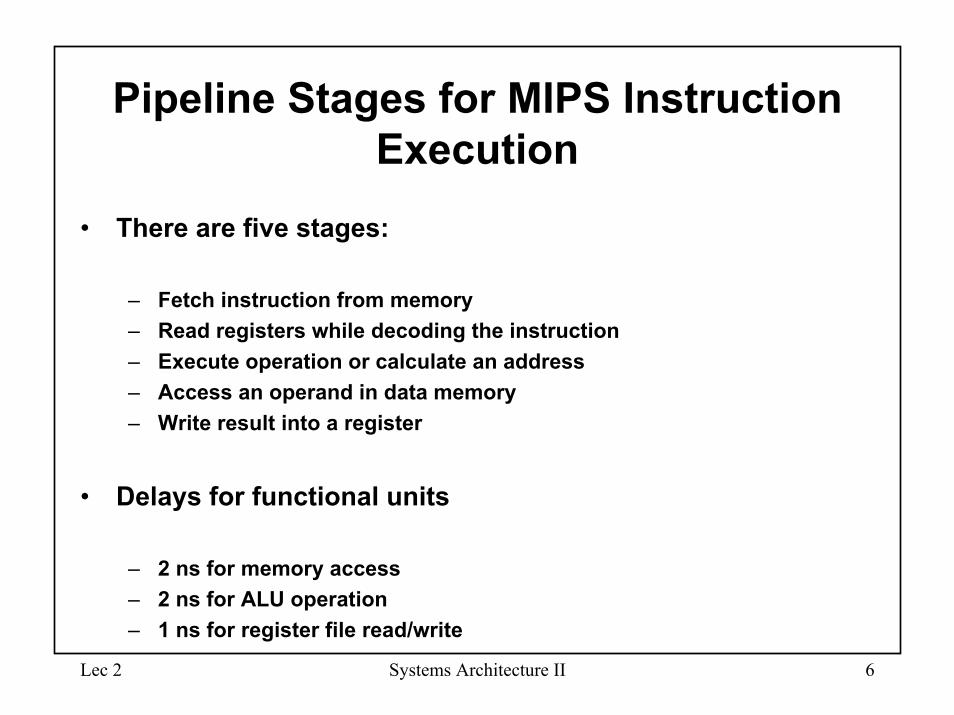
• There are five stages:
– Fetch instruction from memory– Read registers while decoding the instruction– Execute operation or calculate an address– Access an operand in data memory– Write result into a register
• Delays for functional units
– 2 ns for memory access– 2 ns for ALU operation– 1 ns for register file read/write
Lec 2 Systems Architecture II 7
Pipelined Execution for Single-cycle MIPS Implementation
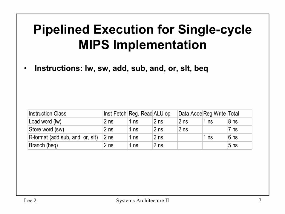
• Instructions: lw, sw, add, sub, and, or, slt, beq
Instruction Class Inst Fetch Reg. Read ALU op Data Acce Reg Write TotalLoad word (lw) 2 ns 1 ns 2 ns 2 ns 1 ns 8 nsStore word (sw) 2 ns 1 ns 2 ns 2 ns 7 nsR-format (add,sub, and, or, slt) 2 ns 1 ns 2 ns 1 ns 6 nsBranch (beq) 2 ns 1 ns 2 ns 5 ns
Lec 2 Systems Architecture II 8
Timing Diagram
Instruction�fetch Reg ALU Data�
access Reg
8 ns Instruction�fetch Reg ALU Data�
access Reg
8 ns Instruction�fetch
8 ns
Time
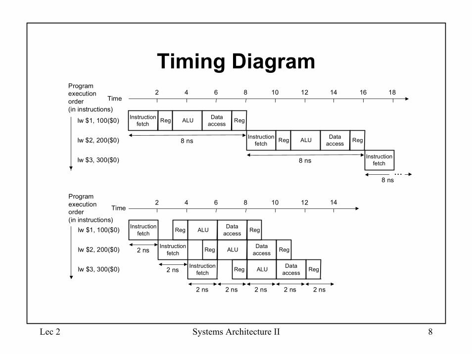
lw $1, 100($0)
lw $2, 200($0)
lw $3, 300($0)
2 4 6 8 10 12 14 16 18
2 4 6 8 10 12 14
...
Program�execution�order�(in instructions)
Instruction�fetch Reg ALU Data�
access Reg
Time
lw $1, 100($0)
lw $2, 200($0)
lw $3, 300($0)
2 ns Instruction�fetch Reg ALU Data�
access Reg
2 ns Instruction�fetch Reg ALU Data�
access Reg
2 ns 2 ns 2 ns 2 ns 2 ns
�
Program�execution�order�(in instructions)

Lec 2 Systems Architecture II 9
Speedup
• Time = (Startup + Number of operations) X time/stage= (Number of stages + Number of operations - 1)
X time/stage
• Speedup = non-pipelined time/pipelined timeIf sequential time = time/stage X number of stages
Speedup = SNt/(S + N-1)t ≈ S,
where S = number of stagesN = number of operationst = time/stage
Lec 2 Systems Architecture II 10
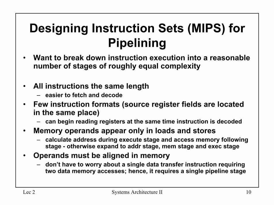
Designing Instruction Sets (MIPS) for Pipelining
• Want to break down instruction execution into a reasonable number of stages of roughly equal complexity
• All instructions the same length– easier to fetch and decode
• Few instruction formats (source register fields are located in the same place)
– can begin reading registers at the same time instruction is decoded• Memory operands appear only in loads and stores
– calculate address during execute stage and access memory following stage - otherwise expand to addr stage, mem stage and exec stage
• Operands must be aligned in memory– don’t have to worry about a single data transfer instruction requiring
two data memory accesses; hence, it requires a single pipeline stage
Lec 2 Systems Architecture II 11
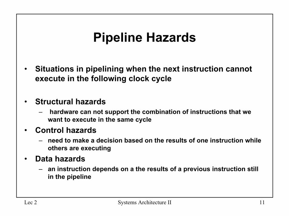
Pipeline Hazards
• Situations in pipelining when the next instruction cannot execute in the following clock cycle
• Structural hazards– hardware can not support the combination of instructions that we
want to execute in the same cycle• Control hazards
– need to make a decision based on the results of one instruction while others are executing
• Data hazards– an instruction depends on a the results of a previous instruction still
in the pipeline
Lec 2 Systems Architecture II 12
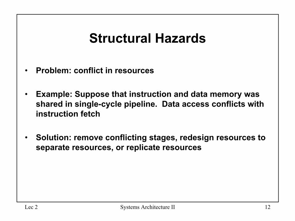
Structural Hazards
• Problem: conflict in resources
• Example: Suppose that instruction and data memory was shared in single-cycle pipeline. Data access conflicts with instruction fetch
• Solution: remove conflicting stages, redesign resources to separate resources, or replicate resources
Lec 2 Systems Architecture II 13
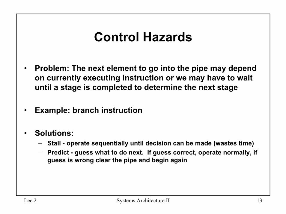
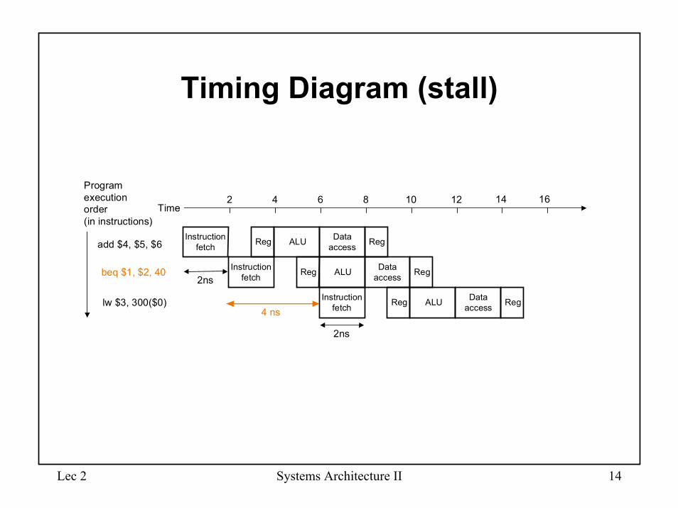
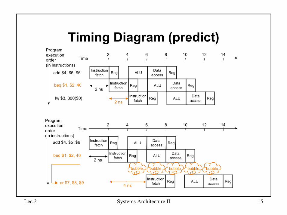
Control Hazards
• Problem: The next element to go into the pipe may depend on currently executing instruction or we may have to wait until a stage is completed to determine the next stage
• Example: branch instruction
• Solutions:– Stall - operate sequentially until decision can be made (wastes time)– Predict - guess what to do next. If guess correct, operate normally, if
guess is wrong clear the pipe and begin again
Lec 2 Systems Architecture II 14
Timing Diagram (stall)
Instruction�fetch Reg ALU Data�
access Reg
Time
beq $1, $2, 40
add $4, $5, $6
lw $3, 300($0)4 ns
Instruction�fetch Reg ALU Data�
access Reg2ns
Instruction�fetch Reg ALU Data�
access Reg
2ns
2 4 6 8 10 12 14 16
�
�
Program�execution�order�(in instructions)
Lec 2 Systems Architecture II 15
Timing Diagram (predict)
Instruction�fetch Reg ALU Data�
access Reg
Time
beq $1, $2, 40
add $4, $5, $6
lw $3, 300($0)
Instruction�fetch Reg ALU Data�
access Reg2 ns
Instruction�fetch Reg ALU Data�
access Reg
�
2 ns
Program�execution�order�(in instructions)
Instruction�fetch Reg ALU Data�
access Reg
Time
beq $1, $2, 40
add $4, $5 ,$6
or $7, $8, $9
Instruction�fetch Reg ALU Data�
access Reg
2 4 6 8 10 12 14
�2 4 6 8 10 12 14
Instruction�fetch Reg ALU Data�
access Reg
2 ns
4 ns
bubble bubble bubble bubble bubble
Program�execution�order�(in instructions)
Lec 2 Systems Architecture II 16
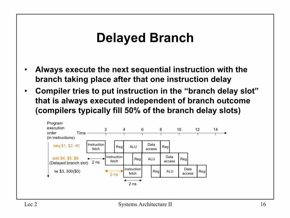
Delayed Branch
• Always execute the next sequential instruction with the branch taking place after that one instruction delay
• Compiler tries to put instruction in the “branch delay slot” that is always executed independent of branch outcome (compilers typically fill 50% of the branch delay slots)
Instruction�fetch Reg ALU Data�
access Reg
Time
beq $1, $2, 40
add $4, $5, $6
lw $3, 300($0)
Instruction�fetch Reg ALU Data�
access Reg2 ns
Instruction�fetch Reg ALU Data�
access Reg
2 ns
2 4 6 8 10 12 14
�
2 ns
(Delayed branch slot)
Program�execution�order�(in instructions)
Lec 2 Systems Architecture II 17
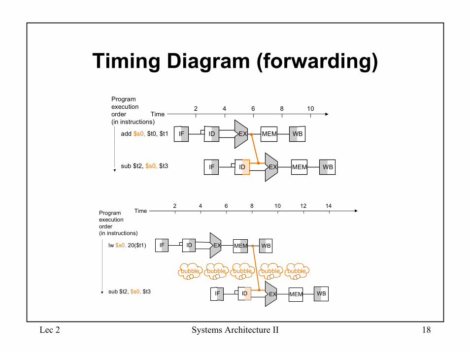
Data Hazards
• Problem: Instruction depends on the result of a previous instruction still in the pipeline
• Example:– add $s0, $t0, $t1– sub $t2, $s0, $t3
• Solutions:– forwarding or bypassing– instruction reordering to remove dependencies
Lec 2 Systems Architecture II 18
Timing Diagram (forwarding)
add $s0, $t0, $t1
sub $t2, $s0, $t3
Program�execution�order�(in instructions)
IF ID WBEX
IF ID MEMEX
Time2 4 6 8 10
MEM
WBMEM
Time2 4 6 8 10 12 14
lw $s0, 20($t1)
sub $t2, $s0, $t3
Program�execution�order�(in instructions)
IF ID WBMEMEX
IF ID WBMEMEX
bubble bubble bubble bubble bubble
Lec 2 Systems Architecture II 19
Summary• Pipelining increases the number of simultaneously
executing instructions and the rate at which instructions are started and completed.
• Pipelining does not reduce the time it takes to complete an individual instruction
– In the five-stage pipeline, it still takes 5 clock cycles for instructions to complete
• Pipelining improves instruction throughput rather than reducing individual instruction execution time
• Good pipeline design requires an appropriate number of stages of comparable complexity (speedup = number of stages)
• Must cope with structural, control, and data hazards• Techniques include: branch prediction, forwarding, and
stalls
Lec 2 Systems Architecture II 20
Improving Pipeline Performance• Superpipelining - very long pipelines
• Superscalar - replicate resources so that multiple instructions can execute in the different stages of the pipeline
– issue multiple instructions in the same cycle
• Dynamic pipeline scheduling - dynamically reorder instructions to avoid hazards.
– usually combined with resource replication– lw $t0, 20($s2)– addu $t1, $t0, $t2– sub $s4, $s4, $t3– slti $t5, $s4, 20
Lec 2 Systems Architecture II 21
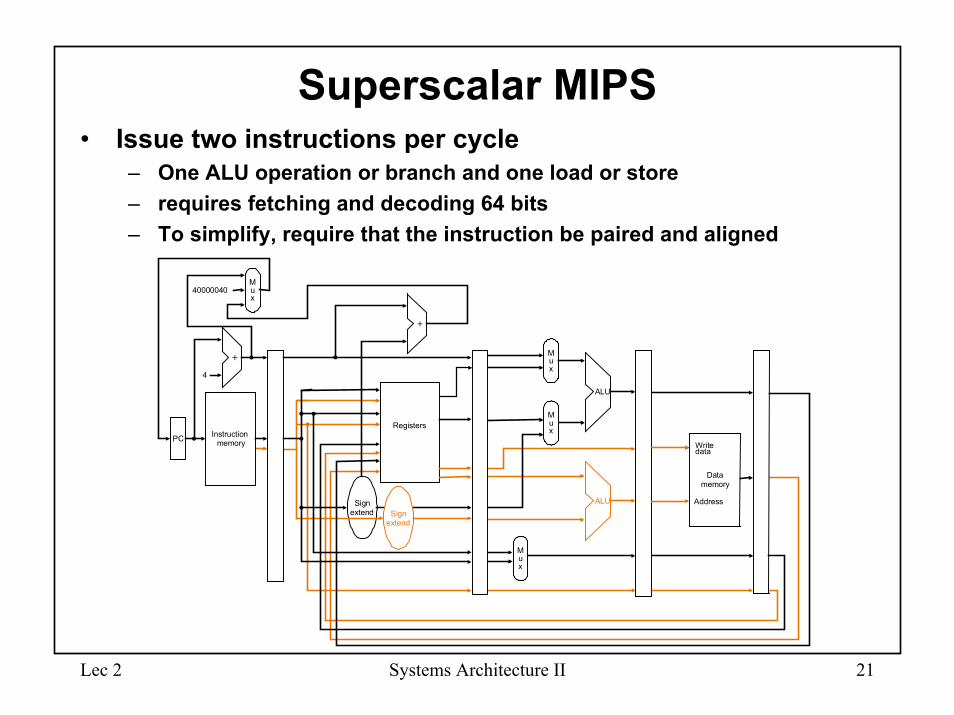
Superscalar MIPS• Issue two instructions per cycle
– One ALU operation or branch and one load or store– requires fetching and decoding 64 bits– To simplify, require that the instruction be paired and aligned
PC Instruction�memory
4
RegistersM�u�x
M�u�x
ALU
M�u�x
Data�memory
M�u�x
40000040
Sign�extend Sign�
extend
ALU Address
Write�data
Lec 2 Systems Architecture II 22
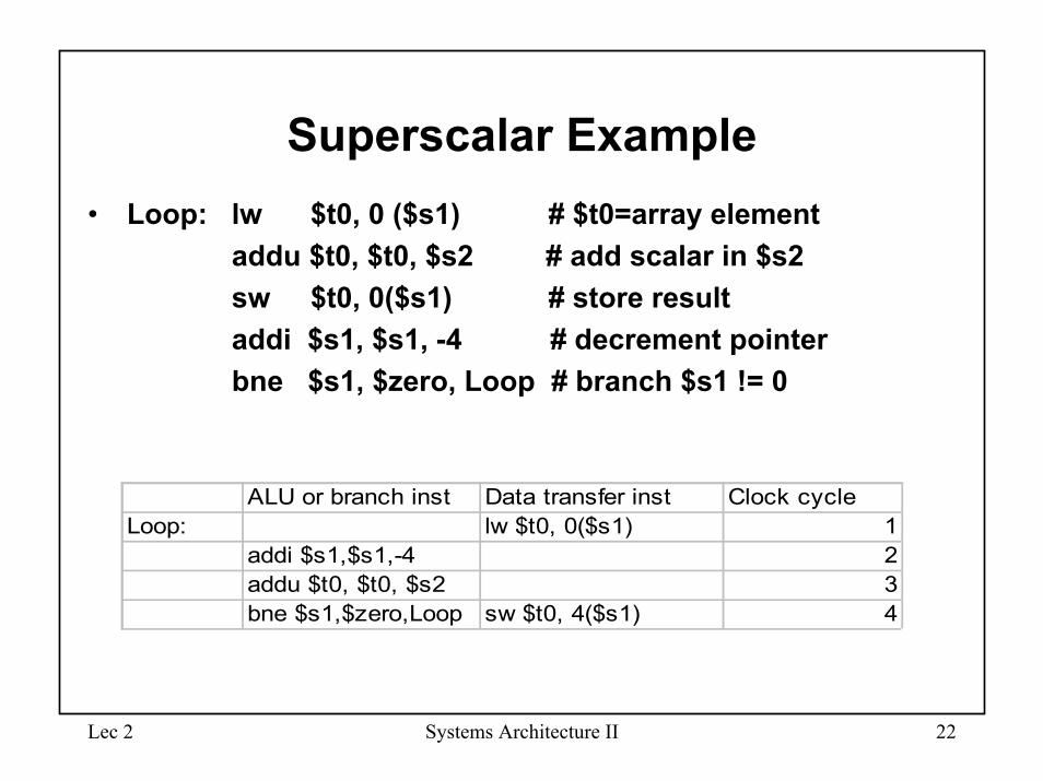
Superscalar Example• Loop: lw $t0, 0 ($s1) # $t0=array element
addu $t0, $t0, $s2 # add scalar in $s2sw $t0, 0($s1) # store resultaddi $s1, $s1, -4 # decrement pointerbne $s1, $zero, Loop # branch $s1 != 0
ALU or branch inst Data transfer inst Clock cycleLoop: lw $t0, 0($s1) 1
addi $s1,$s1,-4 2addu $t0, $t0, $s2 3bne $s1,$zero,Loop sw $t0, 4($s1) 4
Lec 2 Systems Architecture II 23
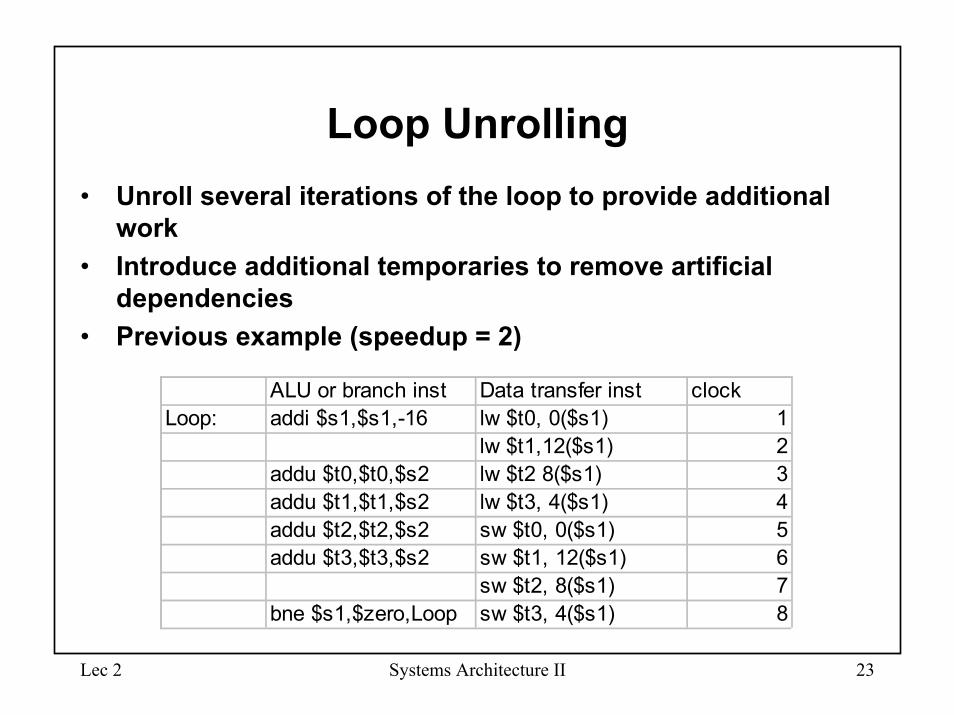
Loop Unrolling• Unroll several iterations of the loop to provide additional
work• Introduce additional temporaries to remove artificial
dependencies• Previous example (speedup = 2)
ALU or branch inst Data transfer inst clockLoop: addi $s1,$s1,-16 lw $t0, 0($s1) 1
lw $t1,12($s1) 2addu $t0,$t0,$s2 lw $t2 8($s1) 3addu $t1,$t1,$s2 lw $t3, 4($s1) 4addu $t2,$t2,$s2 sw $t0, 0($s1) 5addu $t3,$t3,$s2 sw $t1, 12($s1) 6
sw $t2, 8($s1) 7bne $s1,$zero,Loop sw $t3, 4($s1) 8
Lec 2 Systems Architecture II 24
Dynamic Pipeline Scheduling
• Go past stalls to find later instructions to execute while waiting for the stall to be resolved
• Out of order execution• In order completion• Speculative execution (dynamic scheduling + branch
prediction)• Register renaming• Can accomplish automatic loop unrolling
Lec 2 Systems Architecture II 25
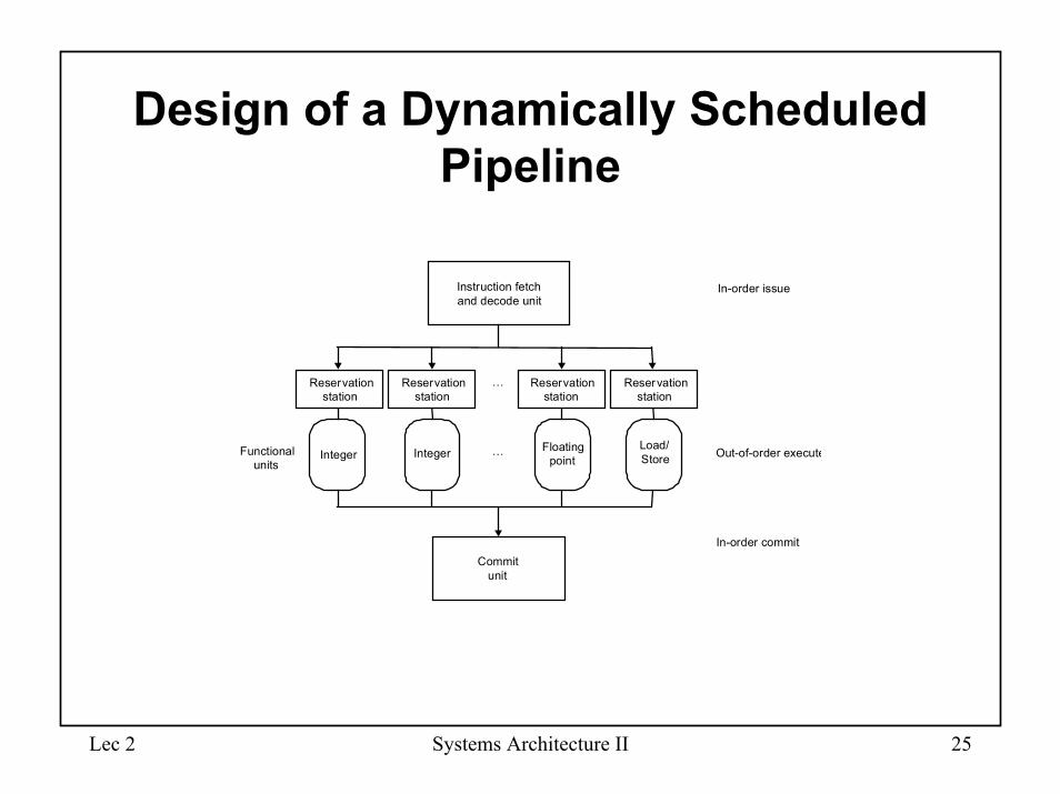
Design of a Dynamically Scheduled Pipeline
Commit�unit
Instruction fetch�and decode unit
…
In-order issue
In-order commit
�
Load/�Store
Floating�pointIntegerInteger …Functional�
unitsOut-of-order execute
Reservation�station
Reservation�station
Reservation�station
Reservation�station
Lec 2 Systems Architecture II 26
Systems Architecture II
Topic 2: Pipelined Datapath and Control
Lec 2 Systems Architecture II 27
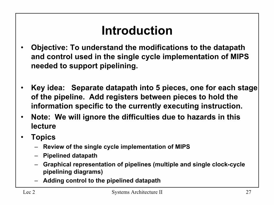
Introduction• Objective: To understand the modifications to the datapath
and control used in the single cycle implementation of MIPS needed to support pipelining.
• Key idea: Separate datapath into 5 pieces, one for each stage of the pipeline. Add registers between pieces to hold the information specific to the currently executing instruction.
• Note: We will ignore the difficulties due to hazards in this lecture
• Topics– Review of the single cycle implementation of MIPS– Pipelined datapath– Graphical representation of pipelines (multiple and single clock-cycle
pipelining diagrams)– Adding control to the pipelined datapath
Lec 2 Systems Architecture II 28
Pipeline Stages for MIPS Instruction Execution
• There are five stages:
– IF: Fetch instruction– ID: Instruction decode and register file – EX: Execution or address calculation– MEM: Data memory access– WB: Write back
Lec 2 Systems Architecture II 29
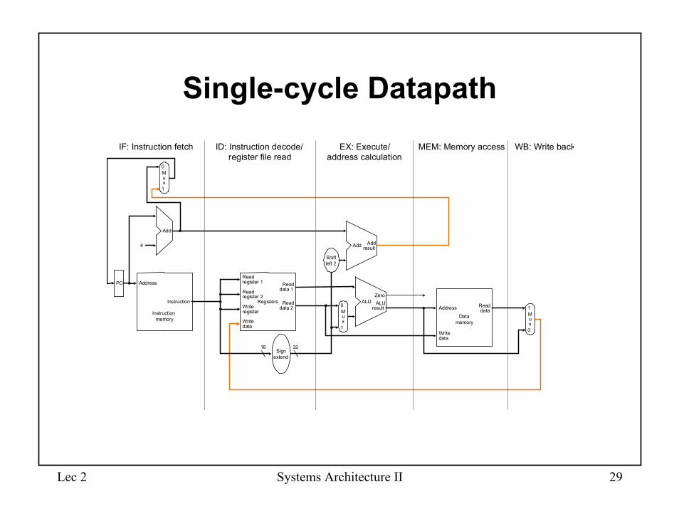
Single-cycle Datapath
Instruction�memory
Address
4
32
0
Add Add�result
Shift�left 2
Instruction
M�u�x
0
1
Add
PC
0Write�data
M�u�x
1Registers
Read�data 1
Read�data 2
Read�register 1
Read�register 2
16Sign�
extend
Write�register
Write�data
Read�dataAddress
Data�memory
1
ALU�result
M�u�x
ALUZero
IF: Instruction fetch ID: Instruction decode/�register file read
EX: Execute/�address calculation
MEM: Memory access WB: Write back
Lec 2 Systems Architecture II 30
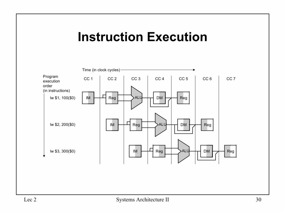
Instruction Execution
IM Reg DM RegALU
IM Reg DM RegALU
CC 1 CC 2 CC 3 CC 4 CC 5 CC 6 CC 7
Time (in clock cycles)
lw $2, 200($0)
lw $3, 300($0)
Program�execution�order�(in instructions)
lw $1, 100($0) IM Reg DM RegALU
Lec 2 Systems Architecture II 31
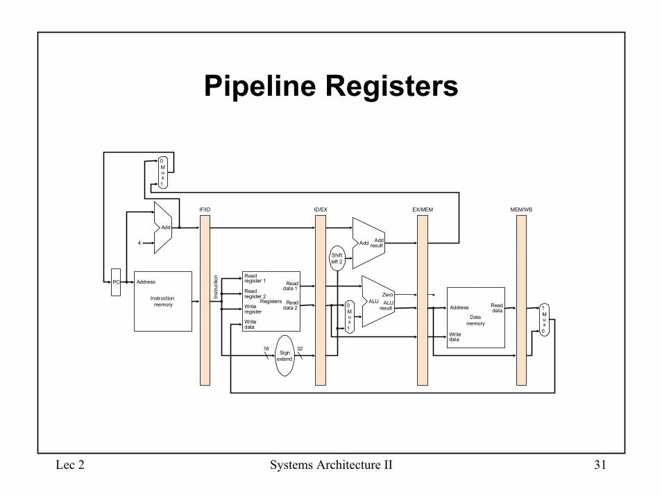
Pipeline Registers
Instruction�memory
Address
4
32
0
Add Add�result
Shift�left 2
Inst
ruct
ion
IF/ID EX/MEM MEM/WB
M�u�x
0
1
Add
PC
0Write�data
M�u�x
1Registers
Read�data 1
Read�data 2
Read�register 1
Read�register 2
16Sign�
extend
Write�register
Write�data
Read�data
1
ALU�result
M�u�x
ALUZero
ID/EX
Data�memory
Address
Lec 2 Systems Architecture II 32
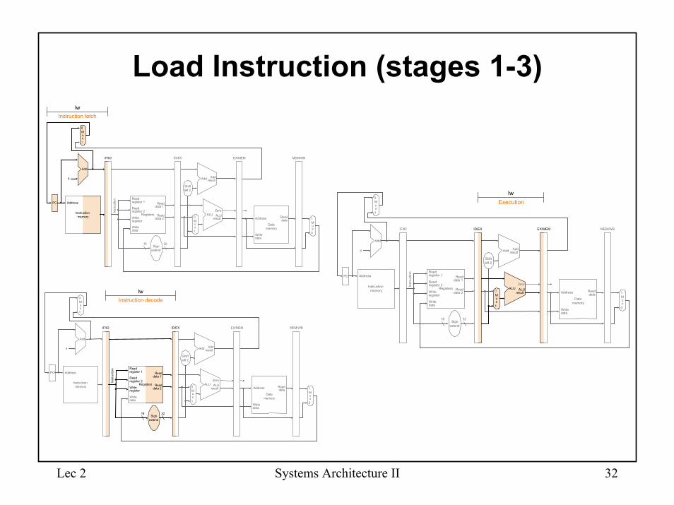
Load Instruction (stages 1-3)
Instruction�memory
Address
4
32
0
Add Add�result
Shift�left 2
Inst
ruct
ion
IF/ID EX/MEM MEM/WB
M�u�x
0
1
Add
PC
0Write�data
M�u�x
1Registers
Read�data 1
Read�data 2
Read�register 1
Read�register 2
16Sign�
extend
Write�register
Write�data
Read�data
1
ALU�result
M�u�x
ALUZero
ID/EX
Instruction fetchlw
Address
Data�memory
Instruction�memory
Address
4
32
0
Add Add�result
Shift�left 2
Inst
ruct
ion
IF/ID EX/MEM
M�u�x
0
1
Add
PC
0Write�data
M�u�x
1Registers
Read�data 1
Read�data 2
Read�register 1
Read�register 2
16Sign�
extend
Write�register
Write�data
Read�data
1
ALU�result
M�u�x
ALUZero
ID/EX MEM/WB
Instruction decodelw
Address
Data�memory
Instruction�memory
Address
4
32
0
Add Add�result
Shift�left 2
Inst
ruct
ion
IF/ID EX/MEM
M�u�x
0
1
Add
PC
0Write�data
M�u�x
1Registers
Read�data 1
Read�data 2
Read�register 1
Read�register 2
16Sign�
extend
Write�register
Write�data
Read�data
1
ALU�result
M�u�x
ALUZero
ID/EX MEM/WB
Executionlw
Address
Data�memory
Lec 2 Systems Architecture II 33
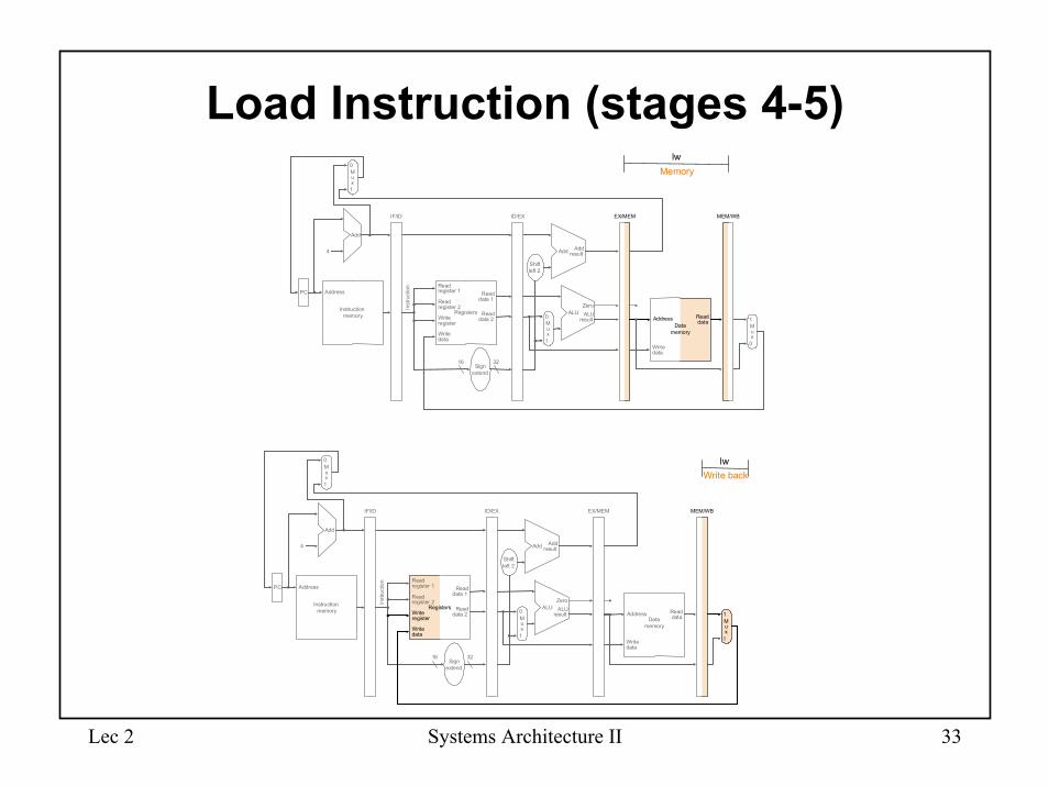
Load Instruction (stages 4-5)
Instruction�memory
Address
4
32
0
Add Add�result
Shift�left 2
Inst
ruct
ion
IF/ID EX/MEM
M�u�x
0
1
Add
PC
0Write�data
M�u�x
1Registers
Read�data 1
Read�data 2
Read�register 1
Read�register 2
16Sign�
extend
Write�register
Write�data
Read�dataData�
memory1
ALU�resultM�
u�x
ALUZero
ID/EX MEM/WB
Memorylw
Address
Instruction�memory
Address
4
32
0
Add Add�result
Shift�left 2
Inst
ruct
ion
IF/ID EX/MEM
M�u�x
0
1
Add
PC
0Write�data
M�u�x
1Registers
Read�data 1
Read�data 2
Read�register 1
Read�register 2
16Sign�
extend
Write�data
Read�dataData�
memory
1
ALU�result
M�u�x
ALUZero
ID/EX MEM/WB
Write backlw
Write�register
Address
Lec 2 Systems Architecture II 34
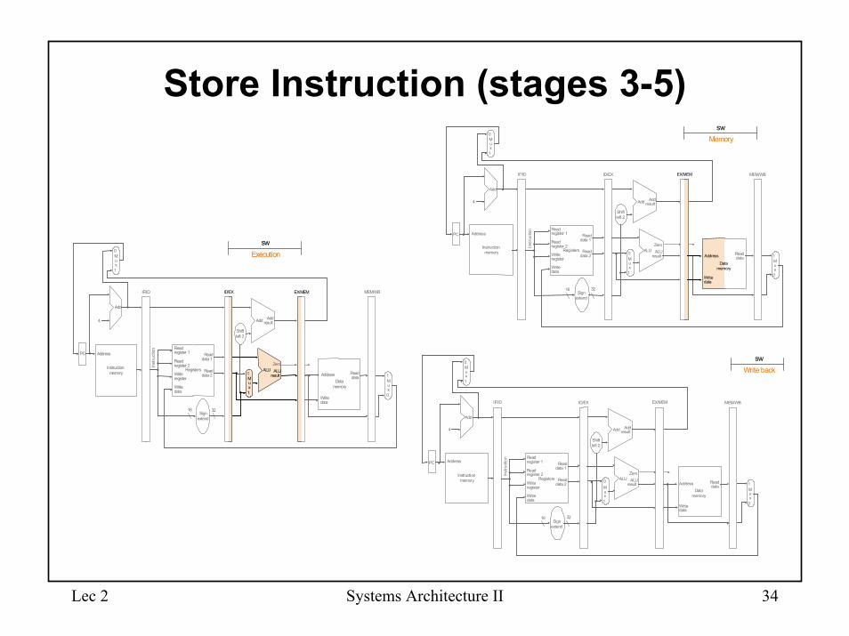
Store Instruction (stages 3-5)
Instruction�memory
Address
4
32
0
Add Add�result
Shift�left 2
Inst
ruct
ion
IF/ID EX/MEM
M�u�x
0
1
Add
PC
0Write�data
M�u�x
1Registers
Read�data 1
Read�data 2
Read�register 1
Read�register 2
16Sign�
extend
Write�register
Write�data
Read�data
Data�memory
1
ALU�resultM�
u�x
ALUZero
ID/EX MEM/WB
Memorysw
Address
Instruction�memory
Address
4
32
0
Add Add�result
Shift�left 2
Inst
ruct
ion
IF/ID EX/MEM
M�u�x
0
1
Add
PC
0
Address
Write�data
M�u�x
1Registers
Read�data 1
Read�data 2
Read�register 1
Read�register 2
16Sign�
extend
Write�register
Write�data
Read�data
Data�memory
1
ALU�result
M�u�x
ALUZero
ID/EX MEM/WB
Write backsw
Instruction�memory
Address
4
32
0
Add Add�result
Shift�left 2
Inst
ruct
ion
IF/ID EX/MEM
M�u�x
0
1
Add
PC
0Write�data
M�u�x
1Registers
Read�data 1
Read�data 2
Read�register 1
Read�register 2
16Sign�
extend
Write�register
Write�data
Read�data
Data�memory
1
ALU�result
M�u�x
ALUZero
ID/EX MEM/WB
Executionsw
Address
Lec 2 Systems Architecture II 35
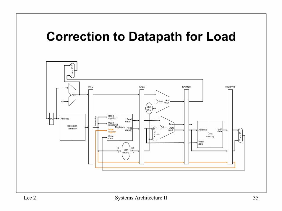
Correction to Datapath for Load
Instruction�memory
Address
4
32
0
Add Add�result
Shift�left 2
Inst
ruct
ion
IF/ID EX/MEM MEM/WB
M�u�x
0
1
Add
PC
0
Address
Write�data
M�u�x
1Registers
Read�data 1
Read�data 2
Read�register 1
Read�register 2
16Sign�
extend
Write�register
Write�data
Read�data
Data�memory
1
ALU�result
M�u�x
ALUZero
ID/EX
Lec 2 Systems Architecture II 36
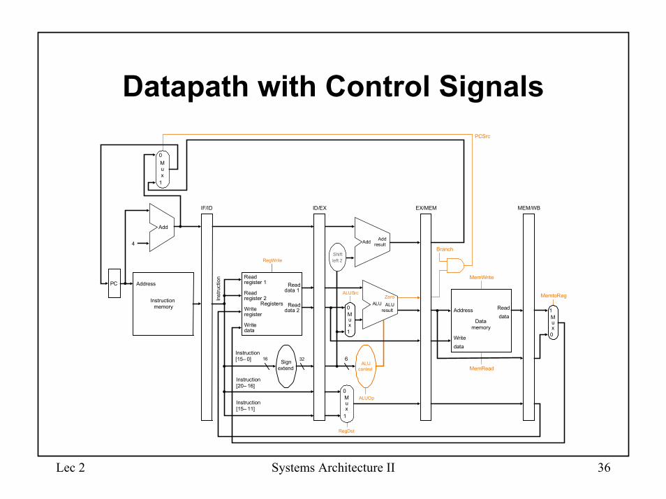
Datapath with Control Signals
PC
Instruction�memory
Address
Inst
ruct
ion
Instruction�[20– 16]
MemtoReg
ALUOp
Branch
RegDst
ALUSrc
4
16 32Instruction�[15– 0]
0
0Registers
Write�register
Write�data
Read�data 1
Read�data 2
Read�register 1
Read�register 2
Sign�extend
M�u�x
1Write�data
Read�data M�
u�x
1
ALU�control
RegWrite
MemRead
Instruction�[15– 11]
6
IF/ID ID/EX EX/MEM MEM/WB
MemWrite
Address
Data�memory
PCSrc
Zero
Add Add�result
Shift�left 2
ALU�result
ALUZero
Add
0
1
M�u�x
0
1
M�u�x
Lec 2 Systems Architecture II 37
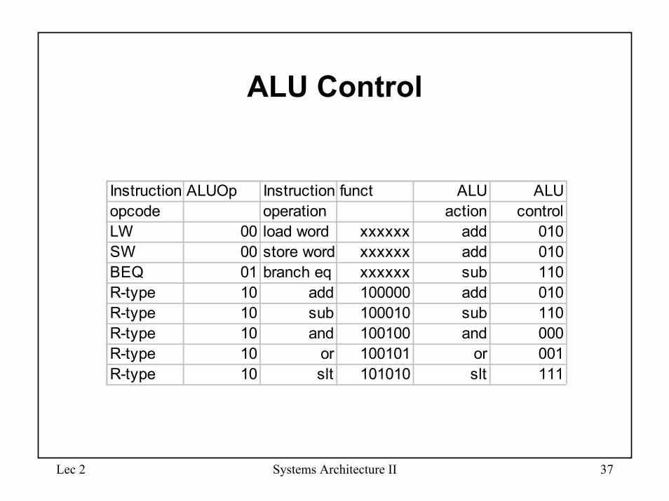
ALU Control
Instruction ALUOp Instruction funct ALU ALUopcode operation action controlLW 00 load word xxxxxx add 010SW 00 store word xxxxxx add 010BEQ 01 branch eq xxxxxx sub 110R-type 10 add 100000 add 010R-type 10 sub 100010 sub 110R-type 10 and 100100 and 000R-type 10 or 100101 or 001R-type 10 slt 101010 slt 111
Lec 2 Systems Architecture II 38
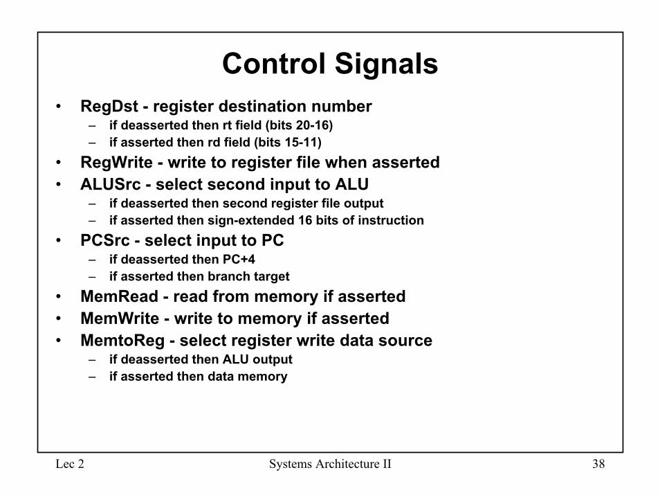
Control Signals• RegDst - register destination number
– if deasserted then rt field (bits 20-16)– if asserted then rd field (bits 15-11)
• RegWrite - write to register file when asserted• ALUSrc - select second input to ALU
– if deasserted then second register file output– if asserted then sign-extended 16 bits of instruction
• PCSrc - select input to PC– if deasserted then PC+4– if asserted then branch target
• MemRead - read from memory if asserted• MemWrite - write to memory if asserted• MemtoReg - select register write data source
– if deasserted then ALU output– if asserted then data memory
Lec 2 Systems Architecture II 39
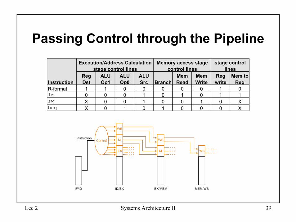
Passing Control through the PipelineExecution/Address Calculation
stage control linesMemory access stage
control linesstage control
lines
InstructionReg Dst
ALU Op1
ALU Op0
ALU Src Branch
Mem Read
Mem Write
Reg write
Mem to Reg
R-format 1 1 0 0 0 0 0 1 0lw 0 0 0 1 0 1 0 1 1sw X 0 0 1 0 0 1 0 Xbeq X 0 1 0 1 0 0 0 X
Control
EX
M
WB
M
WB
WB
IF/ID ID/EX EX/MEM MEM/WB
Instruction
Lec 2 Systems Architecture II 40
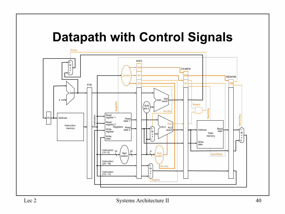
Datapath with Control Signals
PC
Instruction�memory
Inst
ruct
ion
Add
Instruction�[20– 16]
Mem
toR
eg
ALUOp
Branch
RegDst
ALUSrc
4
16 32Instruction�[15– 0]
0
0
M�u�x
0
1
Add Add�result
RegistersWrite�register
Write�data
Read�data 1
Read�data 2
Read�register 1
Read�register 2
Sign�extend
M�u�x
1
ALU�result
Zero
Write�data
Read�data
M�u�x
1
ALU�control
Shift�left 2
Reg
Writ
e
MemRead
Control
ALU
Instruction�[15– 11]
6
EX
M
WB
M
WB
WBIF/ID
PCSrc
ID/EX
EX/MEM
MEM/WB
M�u�x
0
1
Mem
Writ
e
AddressData�
memory
Address
Lec 2 Systems Architecture II 41
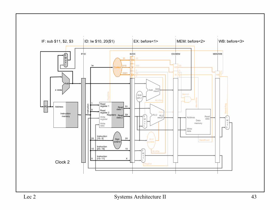
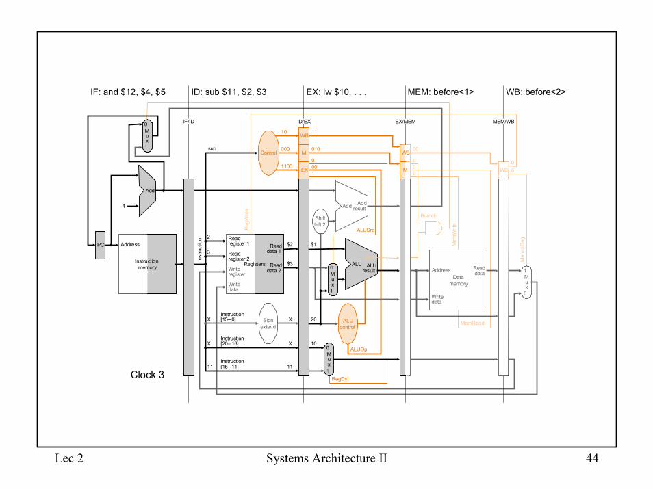
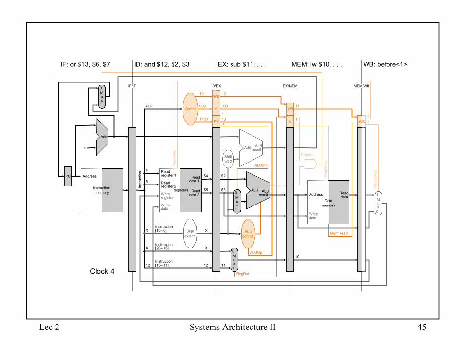
Example
• lw $10, 20($1)• sub $11, $2, $3• and $12, $4, $5• or $13, $6, $7• add $14, $8, $9
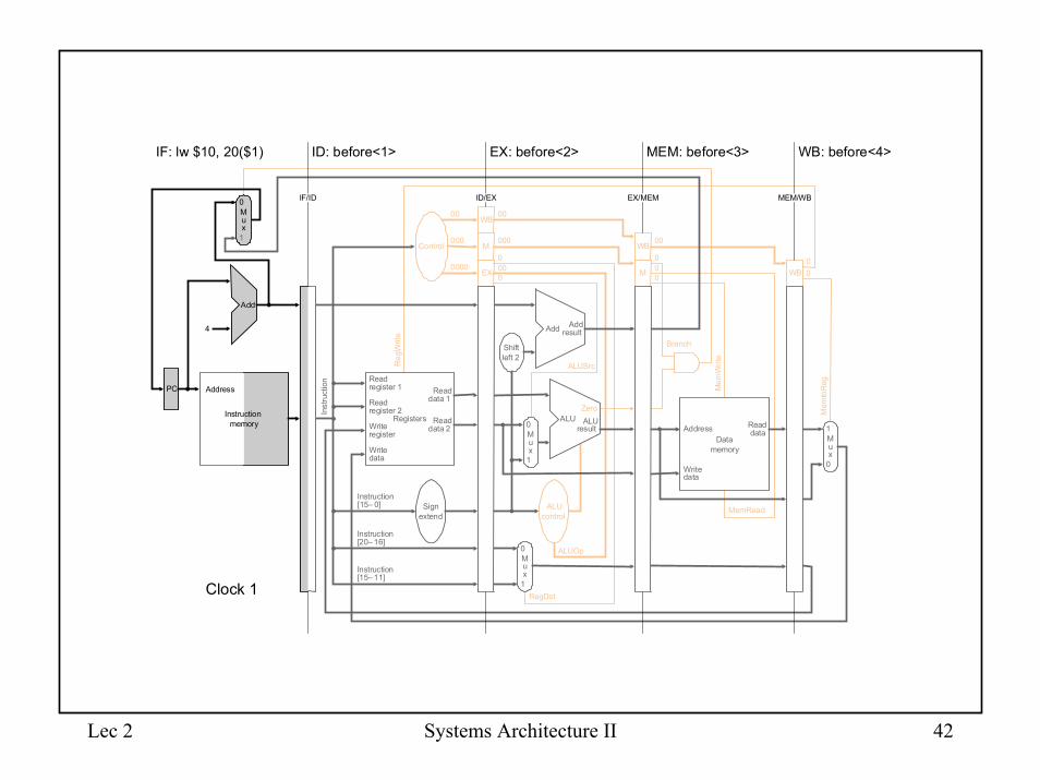
Lec 2 Systems Architecture II 42
Instruction�memory
Instruction�[20– 16]
Mem
toR
eg
ALUOp
Branch
RegDst
ALUSrc
4
Instruction�[15– 0]
0
M�u�x
0
1
Add Add�result
RegistersWrite�register
Write�data
Read�data 1
Read�data 2
Read�register 1
Read�register 2
Sign�extend
M�u�x
1
ALU�result
Zero
ALU�control
Shift�left 2
Reg
Writ
e
MemRead
Control
ALU
Instruction�[15– 11]
EX
M
WB
M
WB
WB
Inst
ruct
ion
IF/ID EX/MEMID/EX
ID: before<1> EX: before<2> MEM: before<3> WB: before<4>
MEM/WB
IF: lw $10, 20($1)
000
00
0000
000
00
000
0
00
00
0
00
M�u�x
0
1
Add
PC
0
Data�memory
Address
Write�data
Read�data
M�u�x
1
Mem
Writ
e
Address
Clock 1
Lec 2 Systems Architecture II 43
WB
EX
M
Instruction�memory
Mem
toR
eg
ALUOp
Branch
RegDst
ALUSrc
4
0
M�u�x
0
1
Add Add�result
Write�register
Write�data
M�u�x
1
ALU�result
Zero
ALU�control
Shift�left 2
Reg
Writ
e
ALU
M
WB
WB
Inst
ruct
ion
IF/ID EX/MEMID/EX
ID: lw $10, 20($1) EX: before<1> MEM: before<2> WB: before<3>
MEM/WB
IF: sub $11, $2, $3
010
11
0001
000
00
000
0
00
00
0
00
M�u�x
0
1
Add
PC
0Write�data
Read�data
M�u�x
1
lwControl
Registers
Read�data 1
Read�data 2
Read�register 1
Read�register 2
X
10
20
X
1
Instruction�[20– 16]
Instruction�[15– 0] Sign�
extend
Instruction�[15– 11]
20
$X
$1
10
X
MemRead
Mem
Writ
e
Data�memory
Address
Address
Clock 2
Lec 2 Systems Architecture II 44
Instruction�memory
Address
Instruction�[20– 16]
Mem
toR
eg
Branch
ALUSrc
4
Instruction�[15– 0]
0
1
Add Add�result
RegistersWrite�register
Write�data
Read�data 1
Read�data 2
Read�register 1
Read�register 2
ALU�result
Shift�left 2
Reg
Writ
e
MemRead
Control
ALU
Instruction�[15– 11]
EX
M
WB
WB
Inst
ruct
ion
IF/ID EX/MEMID/EX
ID: sub $11, $2, $3 EX: lw $10, . . . MEM: before<1> WB: before<2>
MEM/WB
IF: and $12, $4, $5
000
10
1100
010
11
000
1
00
00
0
00
M�u�x
0
1
Add
PC
0Write�data
Read�data
M�u�x
1
Mem
Writ
e
sub
11
X
X
3
2
X
$3
$2
X
11
$1
20
10
M�u�x
0
M�u�x
1
ALUOp
RegDst
ALU�control
M
WB
Zero
Sign�extend
Data�memory
Address
Clock 3
Lec 2 Systems Architecture II 45
WB
EX
M
Instruction�memory
Address
Mem
toR
eg
ALUOp
Branch
RegDst
ALUSrc
4
0
0
1
Add Add�result
Write�register
Write�data 1
ALU�result
ALU�control
Shift�left 2
Reg
Writ
e
M
WB
Inst
ruct
ion
IF/ID EX/MEMID/EX
ID: and $12, $2, $3 EX: sub $11, . . . MEM: lw $10, . . . WB: before<1>
MEM/WB
IF: or $13, $6, $7
000
10
1100
000
10
101
0
11
10
0
00
M�u�x
0
1
Add
PC
0Write�data
M�u�x
1
andControl
Registers
Read�data 1
Read�data 2
Read�register 1
Read�register 2
12
X
X
5
4
Instruction�[20– 16]
Instruction�[15– 0]
Instruction�[15– 11]
X
$5
$4
X
12
MemRead
Mem
Writ
e
$3
$2
11
M�u�x
M�u�x
ALUAddress Read�
dataData�
memory
10
WB
Zero
Sign�extend
Clock 4
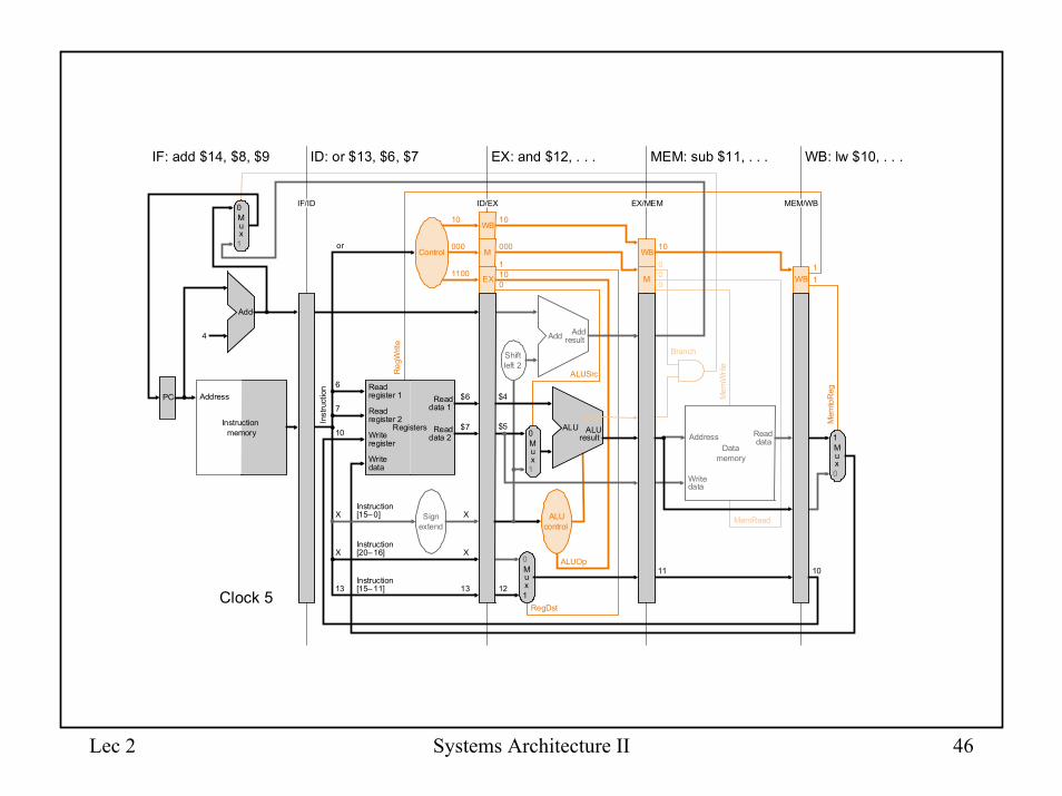
Lec 2 Systems Architecture II 46
Instruction�memory
Address
Instruction�[20– 16]
Branch
ALUSrc
4
Instruction�[15– 0]
0
1
Add Add�result
RegistersWrite�register
Write�data
Read�data 1
Read�data 2
Read�register 1
Read�register 2
ALU�result
Shift�left 2
Reg
Writ
e
MemRead
Control
ALU
Instruction�[15– 11]
EX
M
WB
Inst
ruct
ion
IF/ID EX/MEMID/EX
ID: or $13, $6, $7 EX: and $12, . . . MEM: sub $11, . . . WB: lw $10, . . .
MEM/WB
IF: add $14, $8, $9
000
10
1100
000
10
101
0
10
00
0
M�u�x
0
1
Add
PC
0Write�data
Read�data
M�u�x
1
Mem
Writ
e
or
13
X
X
7
6
X
$7
$6
X
13
$4
M�u�x
0
M�u�x
1
ALUOp
RegDst
ALU�control
M
WB
11 10
10$5
12
WB
Mem
toR
eg
11
Zero
Data�memory
Address
Sign�extend
Clock 5
Lec 2 Systems Architecture II 47
WB
EX
M
Instruction�memory
Address
Mem
toR
eg
ALUOp
Branch
RegDst
ALUSrc
4
0
0
1
Add Add�result
1
ALU�result
ALU�control
Shift�left 2
Reg
Writ
e
M
WB
Inst
ruct
ion
IF/ID EX/MEMID/EX
ID: add $14, $8, $9 EX: or $13, . . . MEM: and $12, . . . WB: sub $11, . . .
MEM/WB
IF: after<1>
000
10
1100
000
10
101
0
10
00
0
10
M�u�x
0
1
Add
PC
0Write�data
M�u�x
1
addControl
Registers
Read�data 1
Read�data 2
Read�register 1
Read�register 2
14
X
X
9
8
Instruction�[20– 16]
Instruction�[15– 0]
Instruction�[15– 11]
X
$9
$8
X
14
MemRead
Mem
Writ
e
$7
$6
13
M�u�x
M�u�x
ALURead�data
12
WB
11
11
Write�register
Write�data
Zero
Data�memory
Address
Sign�extend
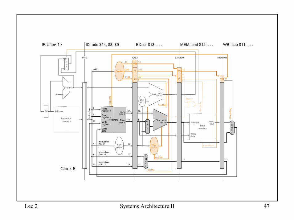
Clock 6
Lec 2 Systems Architecture II 48
Instruction�memory
Address
Instruction�[20– 16]
Branch
ALUSrc
4
Instruction�[15– 0]
0
1
Add Add�result
RegistersWrite�register
Write�data
ALU�result
Shift�left 2
Reg
Writ
e
MemRead
Control
ALU
Instruction�[15– 11]
Sign�extend
EX
M
WB
Inst
ruct
ion
IF/ID EX/MEMID/EX
ID: after<1> EX: add $14, . . . MEM: or $13, . . . WB: and $12, . . .
MEM/WB
IF: after<2>
000
00
0000
000
10
101
0
10
00
0
M�u�x
0
1
Add
PC
0Write�data
Read�data
M�u�x
1
Mem
Writ
e
$8
M�u�x
0
M�u�x
1
ALUOp
RegDst
ALU�control
M
WB
13 12
12$9
14
WB
Mem
toR
eg
10
Read�data 1
Read�data 2
Read�register 1
Read�register 2 Zero
Data�memory
Address
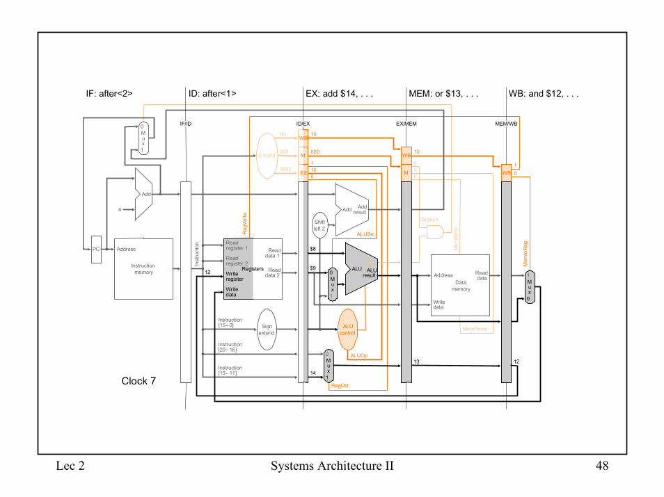
Clock 7
Lec 2 Systems Architecture II 49
WB
EX
M
Instruction�memory
Address
Mem
toR
eg
ALUOp
Branch
RegDst
ALUSrc
4
0
0
1
Add Add�result
1
ALU�result
Zero
ALU�control
Shift�left 2
Reg
Writ
e
M
WB
Inst
ruct
ion
IF/ID EX/MEMID/EX
ID: after<2> EX: after<1> MEM: add $14, . . . WB: or $13, . . .
MEM/WB
IF: after<3>
000
00
0000
000
00
000
0
10
00
0
10
M�u�x
0
1
Add
PC
0Write�data
M�u�x
1
Control
Registers
Read�data 1
Read�data 2
Read�register 1
Read�register 2
Instruction�[20– 16]
Instruction�[15– 0] Sign�
extend
Instruction�[15– 11]
MemRead
Mem
Writ
e
M�u�x
M�u�x
ALURead�data
14
WB
13
13
Write�register
Write�data
Data�memory
Address
Clock 8
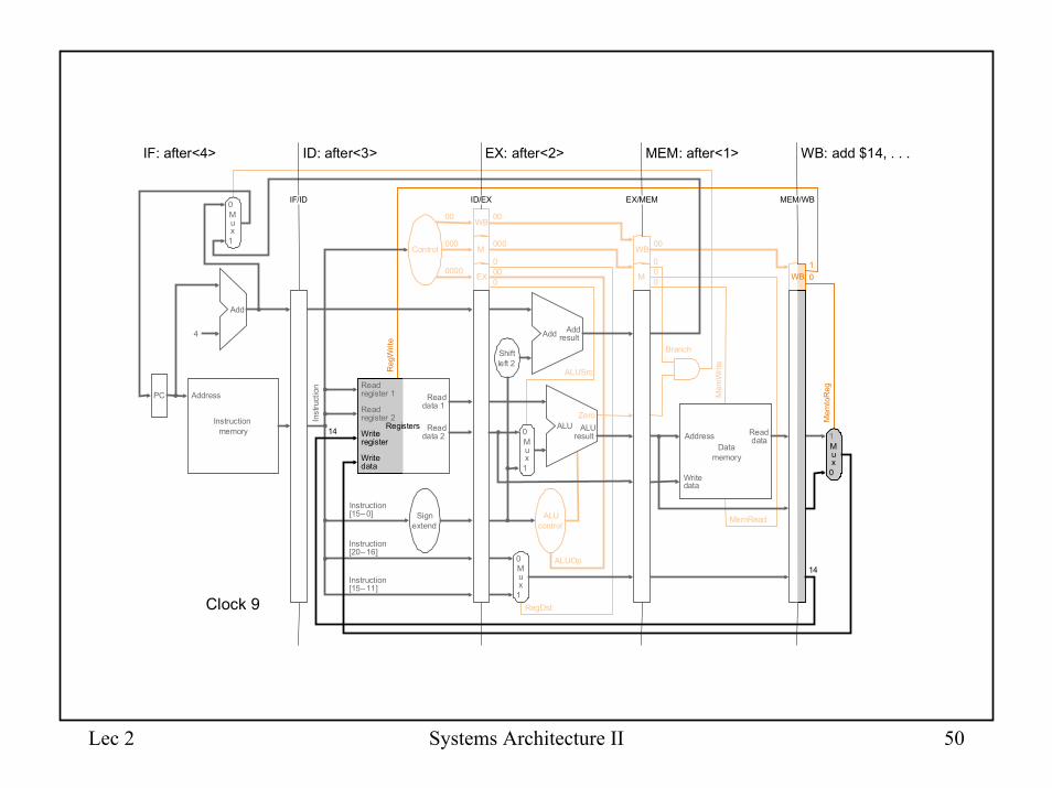
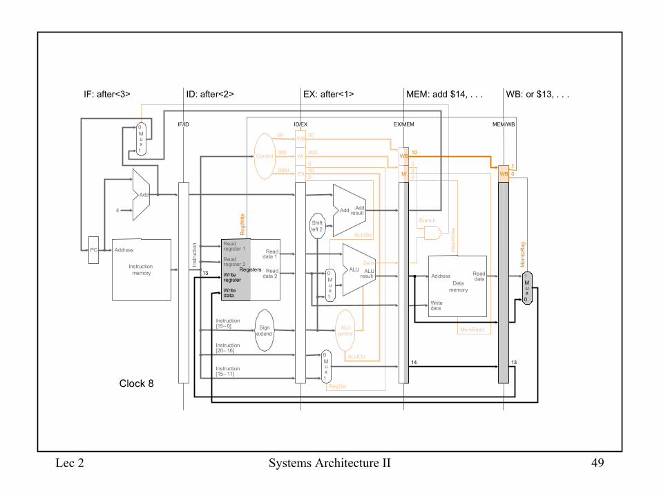
Lec 2 Systems Architecture II 50
WB
EX
M
Instruction�memory
Address
Mem
toR
eg
ALUOp
Branch
RegDst
ALUSrc
4
0
0
1
Add Add�result
1
ALU�result
Zero
ALU�control
Shift�left 2
Reg
Writ
e
M
WB
Inst
ruct
ion
IF/ID EX/MEMID/EX
ID: after<3> EX: after<2> MEM: after<1> WB: add $14, . . .
MEM/WB
IF: after<4>
000
00
0000
000
00
000
0
00
00
0
10
M�u�x
0
1
Add
PC
0Write�data
M�u�x
1
Control
Registers
Read�data 1
Read�data 2
Read�register 1
Read�register 2
Instruction�[20– 16]
Instruction�[15– 0] Sign�
extend
Instruction�[15– 11]
MemRead
Mem
Writ
e
M�u�x
M�u�x
ALURead�data
WB
14
14
Write�register
Write�data
Data�memory
Address
Clock 9


![Mughal Empire- Shahjahan ( Architecture) Part-II [ B.A -II ... · Title: Mughal Empire- Shahjahan ( Architecture) Part-II [ B.A -II History (s) Paper-II] By -Ashish Kr. Thakur Date](https://img.pdfslide.us/doc/110x75/602304b1a8ac11119e59de1c/mughal-empire-shahjahan-architecture-part-ii-ba-ii-title-mughal-empire-.jpg)