Embed Size (px)
Citation preview

HAL Id: hal-02417595https://hal.archives-ouvertes.fr/hal-02417595
Submitted on 18 Dec 2019
HAL is a multi-disciplinary open accessarchive for the deposit and dissemination of sci-entific research documents, whether they are pub-lished or not. The documents may come fromteaching and research institutions in France orabroad, or from public or private research centers.
L’archive ouverte pluridisciplinaire HAL, estdestinée au dépôt et à la diffusion de documentsscientifiques de niveau recherche, publiés ou non,émanant des établissements d’enseignement et derecherche français ou étrangers, des laboratoirespublics ou privés.
3D printing for rapid sand casting-A reviewMeet Upadhyay, Tharmalingam Sivarupan, Mohamed El Mansori
To cite this version:Meet Upadhyay, Tharmalingam Sivarupan, Mohamed El Mansori. 3D printing for rapid sand casting-A review. Journal of Manufacturing Processes, Society of Manufacturing Engineers, 2017, 29, pp.211-220. �10.1016/j.jmapro.2017.07.017�. �hal-02417595�

3
Ma
b
KAS3SRR3
C
1
“ltdi
(
D printing for rapid sand casting—A review
eet Upadhyaya,b, Tharmalingam Sivarupana,∗, Mohamed El Mansoria
MSMP-EA7351, Arts et Métiers ParisTech, 2 Cours des Arts et Métiers, 13617 Aix-en-Provence, FranceNational Institute of Technology, Srinivas Nagar, Surathkal, Mangalore, Karnataka 575025, India
eywords:dditive manufacturingand castingD printingand moldsapid prototyping
a b s t r a c t
There are many 3D printing technologies available, and each technology has its strength and weakness.The 3D printing of sand moulds, by binder jetting technology for rapid casting, plays a vital role inproviding a better value for the more than 5000 years old casting industry by producing quality andeconomic sand moulds. The parts of the mould assembly can be manufactured by precisely controllingthe process parameters and the gas producible materials within the printed mould. A functional mouldcan be manufactured with the required gas permeability, strength, and heat absorption characteristics,and hence the process ensures a high success rate of quality castings with an optimised design for weightreduction. It overcomes many of the limitations in traditional mould design with a very limited numberof parts in the mould assembly. A variety of powders, of different particle size or shape, and bondingmaterials can be used to change the thermal and physical properties of the mould and hence providepossibilities for casting a broad range of alloys. Limited studies have been carried out to understand the
apid manufacturingD sand moulds
relationship between the characteristics of the printed mould, the materials used, and the processingparameters for making the mould. These deficiencies need to be addressed to support the numericalsimulation of a designed part, to optimise the success rate and for economic as well as environmentalreasons. Commonly used binders in this process, e.g. furan resins, are carcinogenic or hazardous, andhence there is a vital need for developing new or improved bonding materials.
ontents
1. Introduction . . . . . . . . . . . . . . . . . . . . . . . . . . . . . . . . . . . . . . . . . . . . . . . . . . . . . . . . . . . . . . . . . . . . . . . . . . . . . . . . . . . . . . . . . . . . . . . . . . . . . . . . . . . . . . . . . . . . . . . . . . . . . . . . . . . . . . . . . . . 2112. Mould properties and their effect on the cast metal . . . . . . . . . . . . . . . . . . . . . . . . . . . . . . . . . . . . . . . . . . . . . . . . . . . . . . . . . . . . . . . . . . . . . . . . . . . . . . . . . . . . . . . . . . . . . . . . . . 2133. Design capability and accuracy. . . . . . . . . . . . . . . . . . . . . . . . . . . . . . . . . . . . . . . . . . . . . . . . . . . . . . . . . . . . . . . . . . . . . . . . . . . . . . . . . . . . . . . . . . . . . . . . . . . . . . . . . . . . . . . . . . . . . . . .2164. Material systems and the issues in the 3D printing technology . . . . . . . . . . . . . . . . . . . . . . . . . . . . . . . . . . . . . . . . . . . . . . . . . . . . . . . . . . . . . . . . . . . . . . . . . . . . . . . . . . . . . . 2185. Conclusions and future perspectives . . . . . . . . . . . . . . . . . . . . . . . . . . . . . . . . . . . . . . . . . . . . . . . . . . . . . . . . . . . . . . . . . . . . . . . . . . . . . . . . . . . . . . . . . . . . . . . . . . . . . . . . . . . . . . . . . . 219
Acknowledgements . . . . . . . . . . . . . . . . . . . . . . . . . . . . . . . . . . . . . . . . . . . . . . . . . . . . . . . . . . . . . . . . . . . . . . . . . . . . . . . . . . . . . . . . . . . . . . . . . . . . . . . . . . . . . . . . . . . . . . . . . . . . . . . . . . . 219References . . . . . . . . . . . . . . . . . . . . . . . . . . . . . . . . . . . . . . . . . . . . . . . . . . . . . . . . . . . . . . . . . . . . . . . . . . . . . . . . . . . . . . . . . . . . . . . . . . . . . . . . . . . . . . . . . . . . . . . . . . . . . . . . . . . . . . . . . . . . . 219
. Introduction
A definition of additive manufacturing (AM) has been given asprocess of joining materials to make parts from 3D model data, usuallyayer upon layer, as opposed to subtractive manufacturing and forma-
Rapid Prototyping (RP) enabled the conversion of parametric CAD(computer aided design) data to physical prototypes which couldbe tested to check if they met the design criteria. This saved notonly time but also allowed the testing of multiple models [2]. Sincethen, its applications have expanded into the aerospace industry,
ive manufacturing methodologies” [1]. AM began as a method foresign engineers to realise design concepts without heavily invest-
ng in the subsequent manufacturing processes. Advancements in
∗ Corresponding author.E-mail addresses: [email protected], [email protected]
T. Sivarupan).
medicine, architecture and more. This expansion has been aided bythe wide-scale development and innovation in additive manufac-turing processes. As the accuracy and the versatility of the processesimprove, the focus of the industry is shifting from Rapid Proto-typing to ‘Rapid Manufacturing’ i.e. the process of manufacturing
complete parts from a rapid prototyping device [3,4]. Wohlers [4]states that machines must allow the production of finished partsand an improvement in materials for better penetration of rapid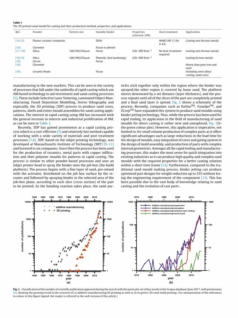
Table 1The 3D printed sand mould for casting and their production method, properties, and applications.
Ref. Powder Particle size Suitable binder Propertiesachieved (3PB)
Heat treatment Application
[14,15] Plaster-ceramic composite Zb56 464K(190◦ C) for4–8 h
Casting non-ferrous metals
[16] Chromite Furan or phenol[17–19] Silica, 140/190/250 �m Furan 250–300 Ncm−2 No heat treatment
requiredCasting non-ferrous metals
[18,19] Silica 140/190/250 �m Phenolic (hot hardening) 250–500 Ncm−2 Casting ferrous metals[16] Zircon Furan[16] Chromite Heavy duty grey iron and
moA[uepcta
copdaftpipwcjt
F[t
[16] Ceramic Beads Furan
anufacturing in the new markets. This can be seen in the varietyf processes that fall under the umbrella of rapid casting which useM based technology to aid investment and sand casting processes
5]. These include Selective Laser Sintering, Laminated Object Man-facturing, Fused Deposition Modelling, Stereo lithography andspecially, the 3D printing (3DP) process to produce sand cores,atterns, shells and entire mould assemblies for sand casting appli-ations. The interest in rapid casting using AM has increased withhe general increase in interest and industrial proliferation of AM,s can be seen in Table 1.
Recently, 3DP has gained prominence as a rapid casting pro-ess which is a cost-effective [5] and relatively fast method capablef working with a wide variety of materials and post treatmentrocesses [7,8]. 3DP, based on the inkjet printing technology, waseveloped at Massachusetts Institute of Technology (MIT) [9–11]nd licensed to six companies. Since then the process has been usedor the production of ceramics, metal parts with copper infiltra-ion and then polymer moulds for patterns in rapid casting. Therocess is similar to other powder-based processes and uses an
nkjet printer head to spray the binder onto the job box (the buildlatform). The process begins with a fine layer of sand, pre-mixed
ith the activator, distributed on the job box surface by the re-oater and followed by spraying binder in the selected area of theob-box plane, according to each slice (cross section) of the parto be printed. As the bonding reaction takes place, the sand par-
ig. 1. Classification of the number of scientific publication appeared during the search wit6], showing the growing trend in the research of (a) additive manufacturing/3D printingo colour in this figure legend, the reader is referred to the web version of this article.)
steelIncluding steel alloyscasting, sand cores
ticles stick together only within the region where the binder wassprayed;the other region is covered by loose sand. The platformmoves downward by a set distance (layer thickness), and the pro-cess repeats until all of the slices of the part are completely printedand a final sand layer is spread. Fig. 2 shows a schematic of theprocess. Recently, companies such as ExOneTM, VoxeljetTM, andZCorpTM have expanded this system to produce sand moulds usingbinder jetting technology. Thus, while the process has been used forrapid tooling, its application in the field of manufacturing of sandmoulds for direct casting is rather new and unexplored, Fig. 1(b-the green colour plot). However, this application is imperative, notlimited to, for small volume production of complex parts as it offerssignificant advantages such as large reductions in the lead time forthe design of moulds, easy integration of cores and gating system inthe design of mold assembly, and production of parts with complexinternal geometries. Amongst all the rapid tooling and manufactur-ing processes, this makes the most sense for quick integration intoexisting industries as it can produce high quality and complex sandmoulds with the required properties for a better casting solutionwithin a short time frame [12]. Furthermore, compared to the tra-ditional sand mould making process, binder jetting can produce
optimised part designs for weight reduction up to 33% without los-ing the engineering requirement of the component [13]. This hasbeen possible due to the vast body of knowledge relating to sandcasting and the evolution of cast parts .h the particular set of key words in the Scopus database (June 2017, with permission)as well as (b-in green) 3D sand mold printing. (For interpretation of the references
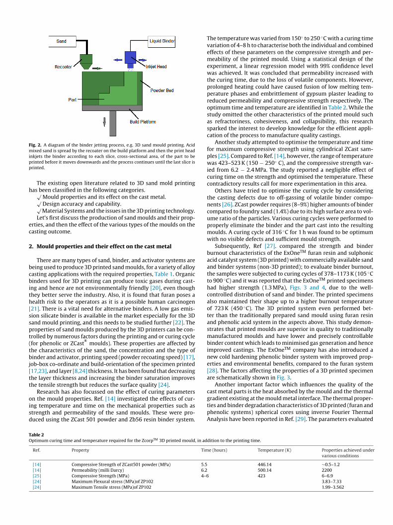
Fig. 2. A diagram of the binder jetting process, e.g. 3D sand mould printing. Acidmixed sand is spread by the recoater on the build platform and then the print headipp
h
ec
2
bcbith[sspt(tbj[tt
oisd
TO
nkjets the binder according to each slice, cross-sectional area, of the part to berinted before it moves downwards and the process continues until the last slice isrinted.
The existing open literature related to 3D sand mold printingas been classified in the following categories.√
Mould properties and its effect on the cast metal.√Design accuracy and capability.√Material Systems and the issues in the 3D printing technology.
Let’s first discuss the production of sand moulds and their prop-rties, and then the effect of the various types of the moulds on theasting outcome.
. Mould properties and their effect on the cast metal
There are many types of sand, binder, and activator systems areeing used to produce 3D printed sand moulds, for a variety of alloyasting applications with the required properties, Table 1. Organicinders used for 3D printing can produce toxic gases during cast-
ng and hence are not environmentally friendly [20], even thoughhey better serve the industry. Also, it is found that furan poses aealth risk to the operators as it is a possible human carcinogen21]. There is a vital need for alternative binders. A low gas emis-ion silicate binder is available in the market especially for the 3Dand mould printing, and this needs to be studied further [22]. Theroperties of sand moulds produced by the 3D printers can be con-rolled by numerous factors during the printing and or curing cyclefor phenolic or ZCast
®moulds). These properties are affected by
he characteristics of the sand, the concentration and the type ofinder and activator, printing speed (powder recoating speed) [17],
ob-box co-ordinate and build-orientation of the specimen printed17,23], and layer [8,24] thickness. It has been found that decreasinghe layer thickness and increasing the binder saturation improveshe tensile strength but reduces the surface quality [24].
Research has also focussed on the effect of curing parameters
n the mould properties. Ref. [14] investigated the effects of cur-ng temperature and time on the mechanical properties such astrength and permeability of the sand moulds. These were pro-uced using the ZCast 501 powder and Zb56 resin binder system.able 2ptimum curing time and temperature required for the ZcorpTM 3D printed mould, in ad
Ref. Property Tim
[14] Compressive Strength of ZCast501 powder (MPa) 5.5[14] Permeability (milli Darcy) 6.2[25] Compressive Strength (MPa) 4–6[24] Maximum Flexural stress (MPa)of ZP102[24] Maximum Tensile stress (MPa)of ZP102
The temperature was varied from 150◦ to 250 ◦C with a curing timevariation of 4–8 h to characterise both the individual and combinedeffects of these parameters on the compressive strength and per-meability of the printed mould. Using a statistical design of theexperiment, a linear regression model with 99% confidence levelwas achieved. It was concluded that permeability increased withthe curing time, due to the loss of volatile components. However,prolonged heating could have caused fusion of low melting tem-perature phases and embrittlement of gypsum plaster leading toreduced permeability and compressive strength respectively. Theoptimum time and temperature are identified in Table 2. While thestudy omitted the other characteristics of the printed mould suchas refractoriness, cohesiveness, and collapsibility, this researchsparked the interest to develop knowledge for the efficient appli-cation of the process to manufacture quality castings.
Another study attempted to optimise the temperature and timefor maximum compressive strength using cylindrical ZCast sam-ples [25]. Compared to Ref. [14], however, the range of temperaturewas 423–523 K (150 − 250◦ C), and the compressive strength var-ied from 6.2 − 2.4 MPa. The study reported a negligible effect ofcuring time on the strength and optimised the temperature. Thesecontradictory results call for more experimentation in this area.
Others have tried to optimise the curing cycle by consideringthe casting defects due to off-gassing of volatile binder compo-nents [26]. ZCast powder requires (8–9%) higher amounts of bindercompared to foundry sand (1.4%) due to its high surface area to vol-ume ratio of the particles. Various curing cycles were performed toproperly eliminate the binder and the part cast into the resultingmoulds. A curing cycle of 316 ◦C for 1 h was found to be optimumwith no visible defects and sufficient mould strength.
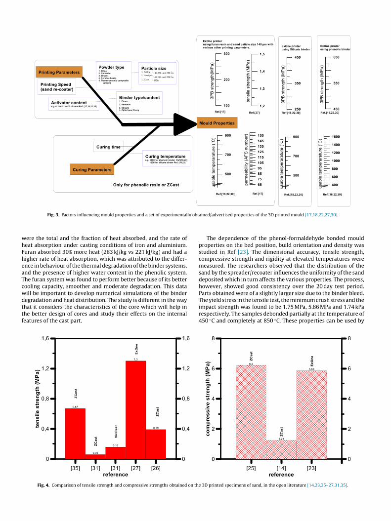
Subsequently, Ref [27]. compared the strength and binderburnout characteristics of the ExOneTM furan resin and sulphonicacid catalyst system (3D printed) with commercially available sandand binder systems (non-3D printed); to evaluate binder burnout,the samples were subjected to curing cycles of 378–1173 K (105 ◦Cto 900 ◦C) and it was reported that the ExOneTM printed specimenshad higher strength (1.3 MPa), Figs. 3 and 4, due to the well-controlled distribution of sand and binder. The printed specimensalso maintained their shape up to a higher burnout temperatureof 723 K (450 ◦C). The 3D printed system even performed bet-ter than the traditionally prepared sand mould using furan resinand phenolic acid system in the aspects above. This study demon-strates that printed moulds are superior in quality to traditionallymanufactured moulds and have lower and precisely controllablebinder content which leads to minimised gas generation and henceimproved castings. The ExOneTM company has also introduced anew cold hardening phenolic binder system with improved prop-erties and environmental benefits, compared to the furan system[28]. The factors affecting the properties of a 3D printed specimenare schematically shown in Fig. 3.
Another important factor which influences the quality of thecast metal parts is the heat absorbed by the mould and the thermal
gradient existing at the mould metal interface. The thermal proper-ties and binder degradation characteristics of 3D printed (furan andphenolic systems) spherical cores using inverse Fourier ThermalAnalysis have been reported in Ref. [29]. The parameters evaluateddition to the printing time.
e (hours) Temperature (K) Properties achieved undervarious conditions
446.14 ∼0.5–1.2500.14 2200423 6–6.9
3.83–7.331.99–3.562
ly obt
whFheaTcwdttf
Fig. 3. Factors influencing mould properties and a set of experimental
ere the total and the fraction of heat absorbed, and the rate ofeat absorption under casting conditions of iron and aluminium.uran absorbed 30% more heat (283 kJ/kg vs 221 kJ/kg) and had aigher rate of heat absorption, which was attributed to the differ-nce in behaviour of the thermal degradation of the binder systems,nd the presence of higher water content in the phenolic system.he furan system was found to perform better because of its betterooling capacity, smoother and moderate degradation. This dataill be important to develop numerical simulations of the binder
egradation and heat distribution. The study is different in the wayhat it considers the characteristics of the core which will help inhe better design of cores and study their effects on the internaleatures of the cast part.Fig. 4. Comparison of tensile strength and compressive strengths obtained on th
ained/advertised properties of the 3D printed mould [17,18,22,27,30].
The dependence of the phenol-formaldehyde bonded mouldproperties on the bed position, build orientation and density wasstudied in Ref [23]. The dimensional accuracy, tensile strength,compressive strength and rigidity at elevated temperatures weremeasured. The researchers observed that the distribution of thesand by the spreader/recoater influences the uniformity of the sanddeposited which in turn affects the various properties. The process,however, showed good consistency over the 20 day test period.Parts obtained were of a slightly larger size due to the binder bleed.
The yield stress in the tensile test, the minimum crush stress and theimpact strength was found to be 1.75 MPa, 5.86 MPa and 1.74 kParespectively. The samples debonded partially at the temperature of450 ◦C and completely at 850 ◦C. These properties can be used bye 3D printed specimens of sand, in the open literature [14,23,25–27,31,35].
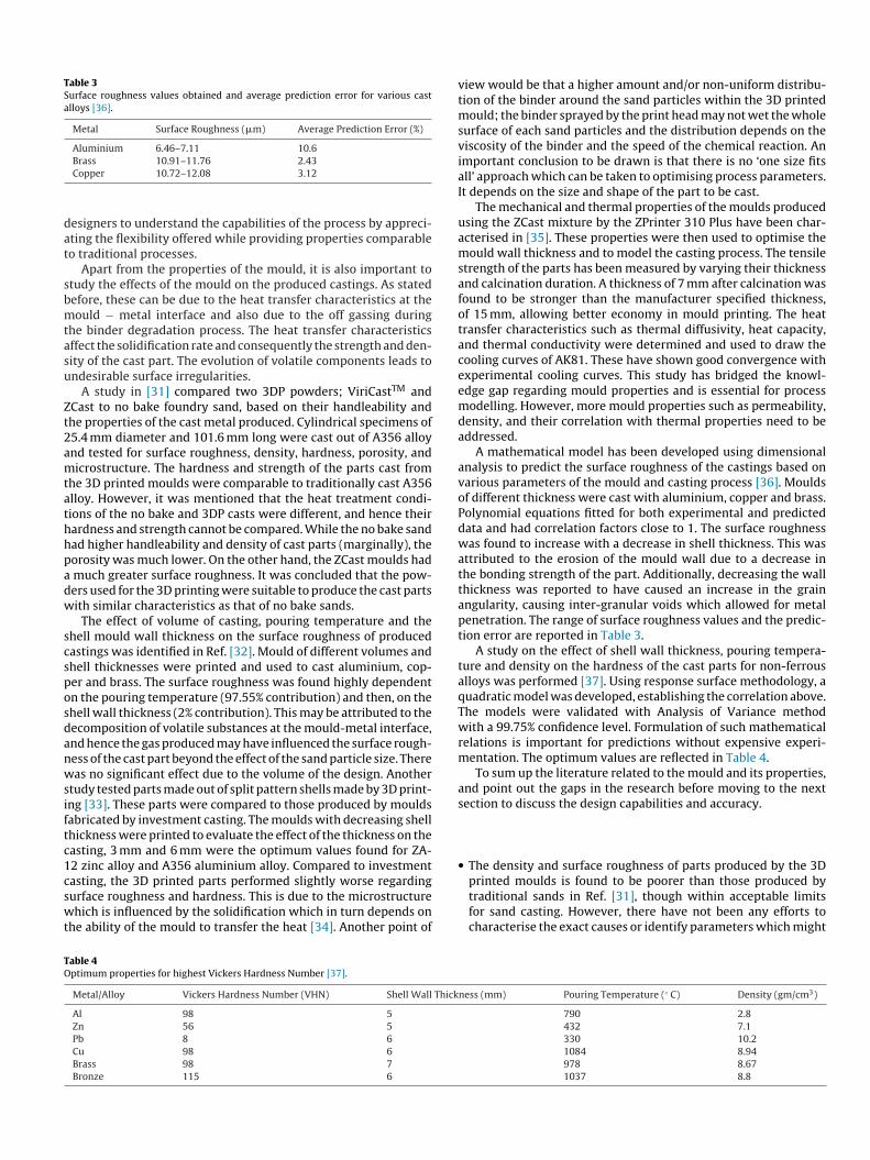
Table 3Surface roughness values obtained and average prediction error for various castalloys [36].
Metal Surface Roughness (�m) Average Prediction Error (%)
Aluminium 6.46–7.11 10.6
dat
sbmtasu
Zt2amtathhpadw
scsposdanwsiftc1cswt
printed moulds is found to be poorer than those produced by
TO
Brass 10.91–11.76 2.43Copper 10.72–12.08 3.12
esigners to understand the capabilities of the process by appreci-ting the flexibility offered while providing properties comparableo traditional processes.
Apart from the properties of the mould, it is also important totudy the effects of the mould on the produced castings. As statedefore, these can be due to the heat transfer characteristics at theould − metal interface and also due to the off gassing during
he binder degradation process. The heat transfer characteristicsffect the solidification rate and consequently the strength and den-ity of the cast part. The evolution of volatile components leads tondesirable surface irregularities.
A study in [31] compared two 3DP powders; ViriCastTM andCast to no bake foundry sand, based on their handleability andhe properties of the cast metal produced. Cylindrical specimens of5.4 mm diameter and 101.6 mm long were cast out of A356 alloynd tested for surface roughness, density, hardness, porosity, andicrostructure. The hardness and strength of the parts cast from
he 3D printed moulds were comparable to traditionally cast A356lloy. However, it was mentioned that the heat treatment condi-ions of the no bake and 3DP casts were different, and hence theirardness and strength cannot be compared. While the no bake sandad higher handleability and density of cast parts (marginally), theorosity was much lower. On the other hand, the ZCast moulds hadmuch greater surface roughness. It was concluded that the pow-ers used for the 3D printing were suitable to produce the cast partsith similar characteristics as that of no bake sands.
The effect of volume of casting, pouring temperature and thehell mould wall thickness on the surface roughness of producedastings was identified in Ref. [32]. Mould of different volumes andhell thicknesses were printed and used to cast aluminium, cop-er and brass. The surface roughness was found highly dependentn the pouring temperature (97.55% contribution) and then, on thehell wall thickness (2% contribution). This may be attributed to theecomposition of volatile substances at the mould-metal interface,nd hence the gas produced may have influenced the surface rough-ess of the cast part beyond the effect of the sand particle size. Thereas no significant effect due to the volume of the design. Another
tudy tested parts made out of split pattern shells made by 3D print-ng [33]. These parts were compared to those produced by mouldsabricated by investment casting. The moulds with decreasing shellhickness were printed to evaluate the effect of the thickness on theasting, 3 mm and 6 mm were the optimum values found for ZA-2 zinc alloy and A356 aluminium alloy. Compared to investmentasting, the 3D printed parts performed slightly worse regarding
urface roughness and hardness. This is due to the microstructurehich is influenced by the solidification which in turn depends onhe ability of the mould to transfer the heat [34]. Another point of
able 4ptimum properties for highest Vickers Hardness Number [37].
Metal/Alloy Vickers Hardness Number (VHN) Shell Wall Thick
Al 98 5Zn 56 5Pb 8 6Cu 98 6Brass 98 7Bronze 115 6
view would be that a higher amount and/or non-uniform distribu-tion of the binder around the sand particles within the 3D printedmould; the binder sprayed by the print head may not wet the wholesurface of each sand particles and the distribution depends on theviscosity of the binder and the speed of the chemical reaction. Animportant conclusion to be drawn is that there is no ‘one size fitsall’ approach which can be taken to optimising process parameters.It depends on the size and shape of the part to be cast.
The mechanical and thermal properties of the moulds producedusing the ZCast mixture by the ZPrinter 310 Plus have been char-acterised in [35]. These properties were then used to optimise themould wall thickness and to model the casting process. The tensilestrength of the parts has been measured by varying their thicknessand calcination duration. A thickness of 7 mm after calcination wasfound to be stronger than the manufacturer specified thickness,of 15 mm, allowing better economy in mould printing. The heattransfer characteristics such as thermal diffusivity, heat capacity,and thermal conductivity were determined and used to draw thecooling curves of AK81. These have shown good convergence withexperimental cooling curves. This study has bridged the knowl-edge gap regarding mould properties and is essential for processmodelling. However, more mould properties such as permeability,density, and their correlation with thermal properties need to beaddressed.
A mathematical model has been developed using dimensionalanalysis to predict the surface roughness of the castings based onvarious parameters of the mould and casting process [36]. Mouldsof different thickness were cast with aluminium, copper and brass.Polynomial equations fitted for both experimental and predicteddata and had correlation factors close to 1. The surface roughnesswas found to increase with a decrease in shell thickness. This wasattributed to the erosion of the mould wall due to a decrease inthe bonding strength of the part. Additionally, decreasing the wallthickness was reported to have caused an increase in the grainangularity, causing inter-granular voids which allowed for metalpenetration. The range of surface roughness values and the predic-tion error are reported in Table 3.
A study on the effect of shell wall thickness, pouring tempera-ture and density on the hardness of the cast parts for non-ferrousalloys was performed [37]. Using response surface methodology, aquadratic model was developed, establishing the correlation above.The models were validated with Analysis of Variance methodwith a 99.75% confidence level. Formulation of such mathematicalrelations is important for predictions without expensive experi-mentation. The optimum values are reflected in Table 4.
To sum up the literature related to the mould and its properties,and point out the gaps in the research before moving to the nextsection to discuss the design capabilities and accuracy.
• The density and surface roughness of parts produced by the 3D
traditional sands in Ref. [31], though within acceptable limitsfor sand casting. However, there have not been any efforts tocharacterise the exact causes or identify parameters which might
ness (mm) Pouring Temperature (◦ C) Density (gm/cm3)
790 2.8432 7.1330 10.21084 8.94978 8.671037 8.8
Tab
le5
Past
stu
die
son
3Dp
rin
ted
mou
ldan
dre
late
dp
rop
erti
esof
the
cast
par
t.
Ref
.Pr
imar
yO
bjec
tive
sM
ould
Prop
erty
Cas
tPr
oper
tySa
nd
&B
ind
erSy
stem
[14]
Op
tim
ise
curi
ng
tim
ean
dte
mp
erat
ure
Com
pre
ssiv
est
ren
gth
and
per
mea
bili
tyZC
ast
501
ZB56
[23]
Ch
arac
teri
sati
onof
mou
ldp
rop
erti
esD
imen
sion
alac
cura
cy,t
ensi
le,
com
pre
ssiv
ean
dim
pac
tte
stin
g,bi
nd
erbu
rnou
t
ExO
ne
san
d+
Sulp
hon
icac
idca
taly
stFu
ran
resi
n
[24]
Effe
ctof
laye
rth
ickn
ess
and
bin
der
satu
rati
onTe
nsi
lean
dfl
exu
rals
tren
gth
,su
rfac
equ
alit
yZP
102
ZB56
[25]
Op
tim
ise
curi
ng
tim
ean
dte
mp
erat
ure
Com
pre
ssiv
est
ren
gth
ZCas
tsy
stem
[26]
Op
tim
ise
curi
ng
cycl
eB
ind
erB
urn
out
Vis
ible
def
ects
ZCas
tsy
stem
[27]
Com
par
ep
rin
ted
and
chem
ical
lybo
un
dsa
nd
mou
lds
Ten
sile
stre
ngt
han
dbi
nd
erbu
rnou
tEx
On
esa
nd
+Su
lph
onic
acid
cata
lyst
Fura
nre
sin
[29]
Det
erm
inat
ion
ofth
erm
alp
rop
erti
esof
san
dco
res
Hea
tab
sorp
tion
and
bin
der
dec
omp
osit
ion
A:
Qu
artz
B:
Cer
abea
ds
A:
Fura
nB
:Ph
enol
ic
[31]
Com
par
ep
rin
ted
and
chem
ical
lybo
un
dsa
nd
mou
lds
Mou
ldst
ren
gth
Surf
ace
rou
ghn
ess,
den
sity
,p
oros
ity,
mic
rost
ruct
ure
Vir
iCas
t,ZC
ast
[32]
Effe
ctof
cast
ing
par
amet
ers
and
mou
ldch
arac
teri
stic
sM
ould
shel
lwal
lth
ickn
ess
Surf
ace
rou
ghn
ess
ZCas
tsy
stem
[33]
Com
par
ison
wit
hin
vest
men
tca
stin
gM
ould
shel
lwal
lth
ickn
ess
Surf
ace
rou
ghn
ess
ZCas
tsy
stem
[35]
Op
tim
ise
mou
ldw
allt
hic
knes
sTe
nsi
lest
ren
gth
,Th
erm
ald
iffu
sivi
ty,
con
du
ctiv
ity,
hea
tca
pac
ity
ZCas
tsy
stem
[36]
Mat
hem
atic
alm
odel
top
red
ict
surf
ace
rou
ghn
ess
Surf
ace
rou
ghn
ess
ZCas
tsy
stem
[37]
Mat
hem
atic
alm
odel
top
red
ict
har
dn
ess
Vic
kers
Har
dn
ess
ZCas
tsy
stem
improve the surface quality. The effect of the binder-catalyst con-centrations should be explored in the future.
• Only a few studies have been aimed at the properties of 3Dprinted cores [29]; it is important to characterise the effects ofthe internal structures in the mould on the cast metal, especiallywhen the design does not allow for proper venting character-istics. This will help identify the process capability for complexinternal geometry.
• Most works have focused on the (e.g. ZCast) printers whichuse powder of plaster-ceramic composition.1 Other systemsusing various sand (e.g. Chromite, Silica, Zircon, or CeramicBeads) −binder (furan or phenol)-catalyst systems (e.g., ExOneTM,VoxeljetTM) may provide better properties, especially due to thelower binder content than the earlier system but not eco-friendlycompared to the previous. Work done on new material systemsis discussed later.
• Aluminium and its alloys have been the focus of most studies.Work is lacking in the area of other wide range of liquidus pointalloys like steel or copper alloys.
• It is worth studying the effect of sand size, binder and activa-tor content and printing speed as these parameters can heavilyinfluence the mould properties.
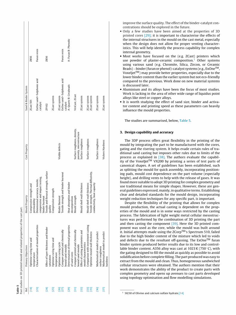
The studies are summarised, below, Table 5.
3. Design capability and accuracy
The 3DP process offers great flexibility in the printing of themould by integrating the part to be manufactured with the cores,gating and the risering system. It helps evade certain rules of tra-ditional sand casting but imposes other rules due to limits of theprocess as explained in [38]. The authors evaluate the capabil-ity of the VoxelJetTM VX200 by printing a series of test parts ofcanonical shapes. A set of guidelines has been established, suchas splitting the mould for quick assembly, incorporating position-ing pads, mould cost dependence on the part volume (especiallyheight), and drilling vents to help with the release of gases. It wasfound more suitable to adopt 3D printing for complex geometry anduse traditional means for simple shapes. However, these are gen-eral guidelines expressed, mainly, in qualitative terms. Establishingclear and detailed standards for the mould design, incorporatingweight reduction techniques for any specific part, is important.
Despite the flexibility of the printing that allows for complexmould production, the actual casting is dependent on the prop-erties of the mould and is in some ways restricted by the castingprocess. The fabrication of light weight metal cellular mesostruc-tures was performed by the combination of 3D printing the partand then casting the component [39]. Here the 3D printed com-ponent was used as the core, while the mould was built aroundit. Initial attempts made using the ZCorpTM’s Spectrum 510, faileddue to the high binder content of the mixture which led to voidsand defects due to the resultant off-gassing. The ExOneTM furanbinder system produced better results due to its low and control-lable binder content. A356 alloy was cast at 1023 K (750 ◦C), withthe gating designed to fill the mould as quickly as possible to avoidsolidification before complete filling. The part produced was easy toextract from the mould and clean. Thus, homogeneous sandwichedcellular structures were obtained. The authors mention that their
work demonstrates the ability of the product to create parts withcomplex geometry and opens up avenues to cast parts developedusing topology optimisation and flow modelling simulations.1 50/50 of Olivine and calcium sulfate hydrate.[14]
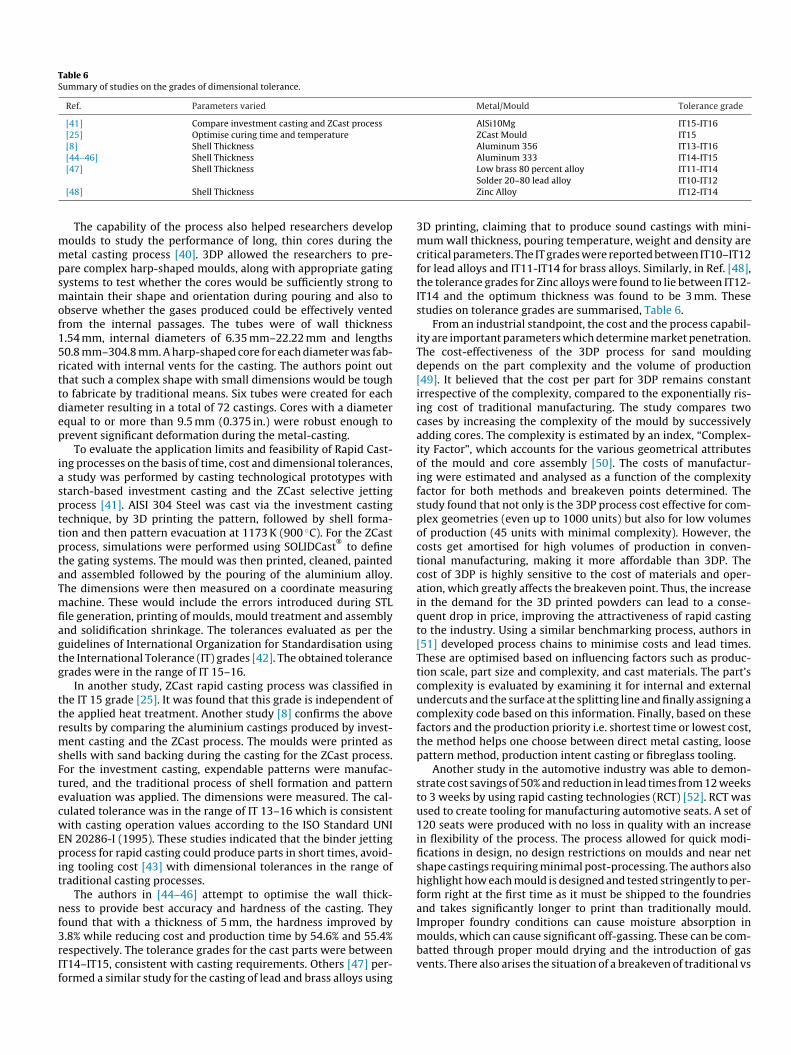
Table 6Summary of studies on the grades of dimensional tolerance.
Ref. Parameters varied Metal/Mould Tolerance grade
[41] Compare investment casting and ZCast process AlSi10Mg IT15-IT16[25] Optimise curing time and temperature ZCast Mould IT15[8] Shell Thickness Aluminum 356 IT13-IT16[44–46] Shell Thickness Aluminum 333 IT14-IT15
mmpsmof15rttdep
iaspttptaTmfiagtg
ttrmsFtecwEpit
nf3rIf
[47] Shell Thickness
[48] Shell Thickness
The capability of the process also helped researchers developoulds to study the performance of long, thin cores during theetal casting process [40]. 3DP allowed the researchers to pre-
are complex harp-shaped moulds, along with appropriate gatingystems to test whether the cores would be sufficiently strong toaintain their shape and orientation during pouring and also to
bserve whether the gases produced could be effectively ventedrom the internal passages. The tubes were of wall thickness.54 mm, internal diameters of 6.35 mm–22.22 mm and lengths0.8 mm–304.8 mm. A harp-shaped core for each diameter was fab-icated with internal vents for the casting. The authors point outhat such a complex shape with small dimensions would be tougho fabricate by traditional means. Six tubes were created for eachiameter resulting in a total of 72 castings. Cores with a diameterqual to or more than 9.5 mm (0.375 in.) were robust enough torevent significant deformation during the metal-casting.
To evaluate the application limits and feasibility of Rapid Cast-ng processes on the basis of time, cost and dimensional tolerances,
study was performed by casting technological prototypes withtarch-based investment casting and the ZCast selective jettingrocess [41]. AISI 304 Steel was cast via the investment castingechnique, by 3D printing the pattern, followed by shell forma-ion and then pattern evacuation at 1173 K (900 ◦C). For the ZCastrocess, simulations were performed using SOLIDCast
®to define
he gating systems. The mould was then printed, cleaned, paintednd assembled followed by the pouring of the aluminium alloy.he dimensions were then measured on a coordinate measuringachine. These would include the errors introduced during STL
le generation, printing of moulds, mould treatment and assemblynd solidification shrinkage. The tolerances evaluated as per theuidelines of International Organization for Standardisation usinghe International Tolerance (IT) grades [42]. The obtained tolerancerades were in the range of IT 15–16.
In another study, ZCast rapid casting process was classified inhe IT 15 grade [25]. It was found that this grade is independent ofhe applied heat treatment. Another study [8] confirms the aboveesults by comparing the aluminium castings produced by invest-ent casting and the ZCast process. The moulds were printed as
hells with sand backing during the casting for the ZCast process.or the investment casting, expendable patterns were manufac-ured, and the traditional process of shell formation and patternvaluation was applied. The dimensions were measured. The cal-ulated tolerance was in the range of IT 13–16 which is consistentith casting operation values according to the ISO Standard UNI
N 20286-I (1995). These studies indicated that the binder jettingrocess for rapid casting could produce parts in short times, avoid-
ng tooling cost [43] with dimensional tolerances in the range ofraditional casting processes.
The authors in [44–46] attempt to optimise the wall thick-ess to provide best accuracy and hardness of the casting. They
ound that with a thickness of 5 mm, the hardness improved by
.8% while reducing cost and production time by 54.6% and 55.4%espectively. The tolerance grades for the cast parts were betweenT14–IT15, consistent with casting requirements. Others [47] per-ormed a similar study for the casting of lead and brass alloys usingLow brass 80 percent alloy IT11-IT14Solder 20–80 lead alloy IT10-IT12Zinc Alloy IT12-IT14
3D printing, claiming that to produce sound castings with mini-mum wall thickness, pouring temperature, weight and density arecritical parameters. The IT grades were reported between IT10–IT12for lead alloys and IT11-IT14 for brass alloys. Similarly, in Ref. [48],the tolerance grades for Zinc alloys were found to lie between IT12-IT14 and the optimum thickness was found to be 3 mm. Thesestudies on tolerance grades are summarised, Table 6.
From an industrial standpoint, the cost and the process capabil-ity are important parameters which determine market penetration.The cost-effectiveness of the 3DP process for sand mouldingdepends on the part complexity and the volume of production[49]. It believed that the cost per part for 3DP remains constantirrespective of the complexity, compared to the exponentially ris-ing cost of traditional manufacturing. The study compares twocases by increasing the complexity of the mould by successivelyadding cores. The complexity is estimated by an index, “Complex-ity Factor”, which accounts for the various geometrical attributesof the mould and core assembly [50]. The costs of manufactur-ing were estimated and analysed as a function of the complexityfactor for both methods and breakeven points determined. Thestudy found that not only is the 3DP process cost effective for com-plex geometries (even up to 1000 units) but also for low volumesof production (45 units with minimal complexity). However, thecosts get amortised for high volumes of production in conven-tional manufacturing, making it more affordable than 3DP. Thecost of 3DP is highly sensitive to the cost of materials and oper-ation, which greatly affects the breakeven point. Thus, the increasein the demand for the 3D printed powders can lead to a conse-quent drop in price, improving the attractiveness of rapid castingto the industry. Using a similar benchmarking process, authors in[51] developed process chains to minimise costs and lead times.These are optimised based on influencing factors such as produc-tion scale, part size and complexity, and cast materials. The part’scomplexity is evaluated by examining it for internal and externalundercuts and the surface at the splitting line and finally assigning acomplexity code based on this information. Finally, based on thesefactors and the production priority i.e. shortest time or lowest cost,the method helps one choose between direct metal casting, loosepattern method, production intent casting or fibreglass tooling.
Another study in the automotive industry was able to demon-strate cost savings of 50% and reduction in lead times from 12 weeksto 3 weeks by using rapid casting technologies (RCT) [52]. RCT wasused to create tooling for manufacturing automotive seats. A set of120 seats were produced with no loss in quality with an increasein flexibility of the process. The process allowed for quick modi-fications in design, no design restrictions on moulds and near netshape castings requiring minimal post-processing. The authors alsohighlight how each mould is designed and tested stringently to per-form right at the first time as it must be shipped to the foundriesand takes significantly longer to print than traditionally mould.Improper foundry conditions can cause moisture absorption in
moulds, which can cause significant off-gassing. These can be com-batted through proper mould drying and the introduction of gasvents. There also arises the situation of a breakeven of traditional vs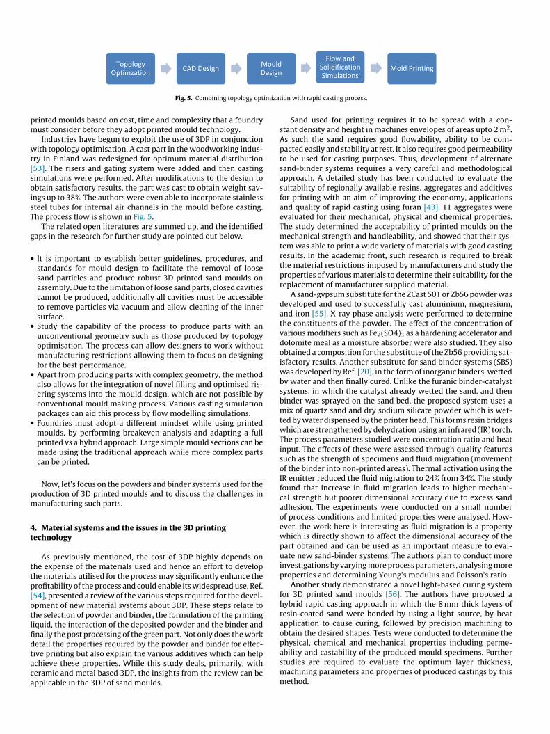
imizat
pm
wt[soisT
g
•
•
•
•
pm
4t
ttp[otlfidtaca
Fig. 5. Combining topology opt
rinted moulds based on cost, time and complexity that a foundryust consider before they adopt printed mould technology.Industries have begun to exploit the use of 3DP in conjunction
ith topology optimisation. A cast part in the woodworking indus-ry in Finland was redesigned for optimum material distribution53]. The risers and gating system were added and then castingimulations were performed. After modifications to the design tobtain satisfactory results, the part was cast to obtain weight sav-ngs up to 38%. The authors were even able to incorporate stainlessteel tubes for internal air channels in the mould before casting.he process flow is shown in Fig. 5.
The related open literatures are summed up, and the identifiedaps in the research for further study are pointed out below.
It is important to establish better guidelines, procedures, andstandards for mould design to facilitate the removal of loosesand particles and produce robust 3D printed sand moulds onassembly. Due to the limitation of loose sand parts, closed cavitiescannot be produced, additionally all cavities must be accessibleto remove particles via vacuum and allow cleaning of the innersurface.Study the capability of the process to produce parts with anunconventional geometry such as those produced by topologyoptimisation. The process can allow designers to work withoutmanufacturing restrictions allowing them to focus on designingfor the best performance.Apart from producing parts with complex geometry, the methodalso allows for the integration of novel filling and optimised ris-ering systems into the mould design, which are not possible byconventional mould making process. Various casting simulationpackages can aid this process by flow modelling simulations.Foundries must adopt a different mindset while using printedmoulds, by performing breakeven analysis and adapting a fullprinted vs a hybrid approach. Large simple mould sections can bemade using the traditional approach while more complex partscan be printed.
Now, let’s focus on the powders and binder systems used for theroduction of 3D printed moulds and to discuss the challenges inanufacturing such parts.
. Material systems and the issues in the 3D printingechnology
As previously mentioned, the cost of 3DP highly depends onhe expense of the materials used and hence an effort to develophe materials utilised for the process may significantly enhance therofitability of the process and could enable its widespread use. Ref.54], presented a review of the various steps required for the devel-pment of new material systems about 3DP. These steps relate tohe selection of powder and binder, the formulation of the printingiquid, the interaction of the deposited powder and the binder andnally the post processing of the green part. Not only does the worketail the properties required by the powder and binder for effec-
ive printing but also explain the various additives which can helpchieve these properties. While this study deals, primarily, witheramic and metal based 3DP, the insights from the review can bepplicable in the 3DP of sand moulds.ion with rapid casting process.
Sand used for printing requires it to be spread with a con-stant density and height in machines envelopes of areas upto 2 m2.As such the sand requires good flowability, ability to be com-pacted easily and stability at rest. It also requires good permeabilityto be used for casting purposes. Thus, development of alternatesand-binder systems requires a very careful and methodologicalapproach. A detailed study has been conducted to evaluate thesuitability of regionally available resins, aggregates and additivesfor printing with an aim of improving the economy, applicationsand quality of rapid casting using furan [43]. 11 aggregates wereevaluated for their mechanical, physical and chemical properties.The study determined the acceptability of printed moulds on themechanical strength and handleability, and showed that their sys-tem was able to print a wide variety of materials with good castingresults. In the academic front, such research is required to breakthe material restrictions imposed by manufacturers and study theproperties of various materials to determine their suitability for thereplacement of manufacturer supplied material.
A sand-gypsum substitute for the ZCast 501 or Zb56 powder wasdeveloped and used to successfully cast aluminium, magnesium,and iron [55]. X-ray phase analysis were performed to determinethe constituents of the powder. The effect of the concentration ofvarious modifiers such as Fe2(SO4)3 as a hardening accelerator anddolomite meal as a moisture absorber were also studied. They alsoobtained a composition for the substitute of the Zb56 providing sat-isfactory results. Another substitute for sand binder systems (SBS)was developed by Ref. [20]. in the form of inorganic binders, wettedby water and then finally cured. Unlike the furanic binder-catalystsystems, in which the catalyst already wetted the sand, and thenbinder was sprayed on the sand bed, the proposed system uses amix of quartz sand and dry sodium silicate powder which is wet-ted by water dispensed by the printer head. This forms resin bridgeswhich are strengthened by dehydration using an infrared (IR) torch.The process parameters studied were concentration ratio and heatinput. The effects of these were assessed through quality featuressuch as the strength of specimens and fluid migration (movementof the binder into non-printed areas). Thermal activation using theIR emitter reduced the fluid migration to 24% from 34%. The studyfound that increase in fluid migration leads to higher mechani-cal strength but poorer dimensional accuracy due to excess sandadhesion. The experiments were conducted on a small numberof process conditions and limited properties were analysed. How-ever, the work here is interesting as fluid migration is a propertywhich is directly shown to affect the dimensional accuracy of thepart obtained and can be used as an important measure to eval-uate new sand-binder systems. The authors plan to conduct moreinvestigations by varying more process parameters, analysing moreproperties and determining Young’s modulus and Poisson’s ratio.
Another study demonstrated a novel light-based curing systemfor 3D printed sand moulds [56]. The authors have proposed ahybrid rapid casting approach in which the 8 mm thick layers ofresin-coated sand were bonded by using a light source, by heatapplication to cause curing, followed by precision machining toobtain the desired shapes. Tests were conducted to determine thephysical, chemical and mechanical properties including perme-
ability and castability of the produced mould specimens. Furtherstudies are required to evaluate the optimum layer thickness,machining parameters and properties of produced castings by thismethod.
m[psddsts(a
udfiutmaptipgttnv
s
•
•
•
5
rsaaftdrrcstifptWmw
[
[
[
[
Researchers also worked on modifying the existing furan binderix to study its curing mechanism and change in thermal strength
57]. The effects of modifiers such as sorbitol, polyester pylols,henol, and acetone were studied using thermal gravity analy-is. The authors use Differential Thermal Analysis to conclude thatehydration polycondensation and ring opening reactions are theominating curing reactions. These result in a three-dimensionaltructure which contributes to the resin strength. The effect ofhe modifiers, except polyester polyol, is minimal on the thermaltrength. This strength improved at temperatures higher than 823 K550 ◦C), and derived a conclusion that the modified resin is a suit-ble candidate for core moulding.
Apart from the research in new materials for additively man-factured moulds, there have been innovations in the powderelivery and printing machines. VoxeljetTM revealed the world’srst continuous 3D printer at EuroMould 2012 [58,59]. The printerses a horizontal belt conveyor which is inclined at an angle lesshan the angle of repose of the sand. After every layer, the conveyor
oves the entire fill by one layer thickness towards the unloadingrea. The main advantage of the process is the simultaneous partrinting and unloading. Also, the unused sand is directly returnedo the build zone post unpacking. In addition to the virtually unlim-ted length of the mould produced, the process also promises fasterrinting as positioning on an incline is faster. This process showsreat promise for mass production and may lead to better accep-ance of the process across the market. A study on the dimensionalolerance of casting produced using these moulds and design tech-iques to produce long and narrow channels containing parts ofarious casting alloys is essential.
To sum up the literature and the gaps in the research for furthertudy,
Considering environmental, health and safety issues, the toxicityof the furan resin must be addressed. New material systems mustbe developed for the rapid sand casting process.It is important to delve into the mechanics of flow of binderthrough the granular sand media to understand the bonding char-acteristics of the material systems.As more new binder-powder systems for 3D printed mouldsdevelop, it will become necessary to set standards for the properevaluation and testing of these moulds and subsequently theparts produced by such moulds.
. Conclusions and future perspectives
Innovative hybrid solutions have now come to the forefront withapid developments in the additive manufacturing industry. Theuitability of 3DP to rapid sand casting applications has led to thedoption of the process by large-scale manufacturers but it is stilllong way to go before its presence is ubiquitous in smaller scale
oundries. Nevertheless, it is still being utilised by these foundrieshrough build-to-order by large enterprises, for prototyping a newesign. Its relatively high initial investment, running and mate-ial costs, and limitations on production volume have hindered itsapid penetration into today’s markets. While it offers a signifi-ant advantage by way of mould complexity, the printing is muchlower than traditional moulding processes for large scale produc-ion. Unless a field of 3D printers is employed, the slow speed makest unsuitable for large scale daily production. Additionally, there is,or now, a limit on the size of the job-box, which requires one toroduce moulds in multiple parts which must then be assembled
ogether, and hence production of large castings become difficult.hile the process is not poised to completely replace the traditionaloulding, by furthering research in this direction, the advantagesill soon be able to outweigh the limitations, enabling this tech-
[
[
nology to be universally accepted and utilised as a complement totraditional moulding practices.
The cost of the currently available materials for sand 3DP can bereduced with the demand in the near future as the research focusin the field and the number of newly released advanced 3D printersare in the increasing trend. This demand is currently limited by thehigh initial investment and running cost of the machines. Hence,an improvement in materials for the rapid casting industry is vitalimportant for better acceptance of the process. Currently, materialsupply is controlled by machine manufacturers and thus it is dif-ficult for academics to experiment with different materials and toestablish their properties. Research focus on developing new mate-rials compatible with commercial systems will aid in developmentof the process.
3D sand mould printing technology provides an excellent solu-tion to the industry need, with minimal change to the currentcasting industry; only the sand mould assembly is produced, andthe casting process will be the same based on the millenniums ofthe knowledge base. It eliminates many of the design rules for sandcasting and still be the better option for rapid prototyping and evencomparable better technology than the direct metal printing tech-nology when considering a large scale castable part design with avariety of alloy material choice and optimised part design. It stilllacks the design knowledge to successfully and economically pro-duce a very complex part with narrow and long channels in thedesign, whereas the direct metal printing can easily be utilised atthe expense of time and money.
Acknowledgements
1st author greatly acknowledges the financial support for thiswork, and to visit MSMP laboratory in France, to carry out other 3Dprinting related experimental work, by the Campus France throughthe Charpak Scholarship scheme.
References
[1] F42.91. Standard Terminology for Additive Manufacturing − General Principles− Terminology. ASTM Int; 2015.
[2] Wong KV, Hernandez A. A review of additive manufacturing. ISRN Mech Eng2012;2012:1–10, http://dx.doi.org/10.5402/2012/208760.
[3] Bak D. Rapid prototyping or rapid production? 3D printing processesmove industry towards the latter. Assem Autom 2003;23:340–5,http://dx.doi.org/10.1108/01445150310501190.
[4] Wohlers T. Wohlers report 2003: Additive manufacturing and 3D printing stateof the industry: Annual worldwide progress report; 2003.
[5] Chhabra M, Singh R. Rapid casting solutions: a review. Rapid Prototyp J2011;17:328–50, http://dx.doi.org/10.1108/13552541111156469.
[6] Scopus Analyze search results 2017: Documents Query [170613–005374]https://www.scopus.com/search/form.uri.
[7] Dimitrov D, Schreve K, De Beer N. Advances in three dimensional printing− state of the art and future perspectives. Rapid Prototyp J 2006;12:136–47,http://dx.doi.org/10.1108/13552540610670717.
[8] Gill SS, Kaplas M. Comparative study of 3D printing technologies forrapid casting of aluminium alloy. Mater Manuf Process 2009;24:1405–11,http://dx.doi.org/10.1080/10426910902997571.
[9] Pham D, Gault R. A comparison of rapid prototypingtechnologies. Int J Mach Tools Manuf 1998;38:1257–87,http://dx.doi.org/10.1016/S0890-6955(97)00137-5.
10] Sachs E, Cima M, Three-Dimensional Printing: Rapid Tooling Cornie J. Proto-types directly from a CAD model. CIRP Ann Manuf Technol 1990;39:201–4.
11] Sachs EM, Haggerty JS, Cima MJ, Williams PA. Three-dimensional printingtech-niques; 1993.
12] Low Z-XX, Chua YT, Ray BM, Mattia D, Metcalfe IS, Patterson DA. Per-spective on 3D printing of separation membranes and comparison torelated unconventional fabrication techniques. J Memb Sci 2017;523:596–613,http://dx.doi.org/10.1016/j.memsci.2016.10.006.
13] ExOne. A Case Study in Optimizing Casting Design Using 3 D Printing; 2017
http://www.afsinc.org/multimedia/MCTVDetail.cfm?ItemNumber=19145.14] Mckenna N, Singamneni S, Diegel O, Singh D, Neitzert T, George JS, et al. DirectMetal casting through 3D printing: a critical analysis of the mould characteris-tics. 9th Glob Congr Manuf Manag 2008:12–4.
15] ZPrinter ® Consumables Catalogue (2013).

[
[
[
[
[
[
[
[
[
[
[
[
[
[
[
[
[
[
[
[
[
[
[[
[
[
[
[
[
[
[
[
[
[
[
[
[
[
[
[
[
[57] Renhe H, Hongmei G, Yaoji T, Qingyun L. Curing mechanism of furan resinmodified with different agents and their thermal strength. China Foundry2011;8:161–5.
[58] VXC800. World’s first 3D continuous printer. 3ders; 2012.[59] Continuous 3D Printer Foundry Manag Technol; 2012.
16] ExOne. ExOne offers a variety of manufacturing quality materials that stand upto industrial use and easy integration into existing processes; 2017 (accessedJune 13, 2017) http://www.exone.com/Resources/Materials.
17] Sivarupan T, ElMansori M, Coniglio N. 3D printing process parameters and prop-erties of additively manufactured sand mold for rapid casting: strength andpermeability. Addit Manuf 2017 (accepted).
18] ExOne. Production Printers n.d. http://www.exone.com/Systems/Production-Printers (accessed February 9, 2017).
19] Voxeljet Sand casting molds - Rapid and economical n.d. http://www.voxeljet.de/en/materials/sand/ (accessed February 2, 2017).
20] Ramakrishnan R, Griebel B, Volk W, Günther D, Günther J,Günther D, et al. 3D printing of inorganic sand mouldsfor casting applications. Adv Mater Res 2014;1018:441–9,http://dx.doi.org/10.4028/www.scientific.net/AMR.1018.441.
21] Bakhiya N, Appel KE. Toxicity and carcinogenicity of furan in human diet. ArchToxicol 2010;84:563–78, http://dx.doi.org/10.1007/s00204-010-0531-y.
22] ExOne. 3D Printing Binders; 2017 (accessed March 13, 2017) http://www.exone.com/Resources/Binders.
23] Hackney PM, Wooldridge R. Characterisation of direct 3D sand printing processfor the production of sand cast mould tools. Rapid Prototyp J 2017;23:7–15,http://dx.doi.org/10.1108/RPJ-08-2014-0101.
24] Vaezi M, Chua CK. Effects of layer thickness and binder saturation levelparameters on 3D printing process. Int J Adv Manuf Technol 2011;53:275–84,http://dx.doi.org/10.1007/s00170-010-2821-1.
25] Bassoli E, Atzeni E. Direct metal rapid casting: mechanical optimiza-tion and tolerance calculation. Rapid Prototyp J 2009;15:238–43,http://dx.doi.org/10.1108/13552540910979758.
26] Snelling DA, Kay R, Druschitz A, Williams CB. Mitigating gas defects in castingsproduced from 3D printed molds. 117th Met Congr 2012:3–9.
27] Snelling D, Williams CB, Druschitz AP. A comparison of binder burnout andmechanical characteristics of printed and chemically bonded sand molds. SFFSymp 2014:197–209.
28] Bednarz M. Cold Hardening Phenol: The new all-rounder among bindersystems. ExOne; 2017 (accessed March 30, 2017) http://www.exone.com/About-ExOne/News/View/ArticleId/67/Cold-hardening-phenol-The-new-all-rounder-among-binder-systems.
29] Svidró JT, Diószegi A. Heat absorption capacity and binder degradation char-acteristics of 3D printed cores investigated by inverse Fourier thermal analysisHeat Absorption Capacity and Binder Degradation Characteristics of 3D PrintedCores Investigated by Inverse Fourier Therma; 2015.
30] Stevenson D. 3D Sand Printing -Cores & Moulds for the Foundry IndustryAgenda; 2015.
31] Snelling D, Blount H, Forman C, Ramsburg K, Wentzel A, Williams C, et al.The effects of 3D pritned molds on metal castings. Solid Free Fabr Symp2013:827–45.
32] Chhabra M, Singh R. Obtaining desired surface roughness of cast-ings produced using ZCast direct metal casting process throughTaguchi's experimental approach. Rapid Prototyp J 2012;18:458–71,http://dx.doi.org/10.1108/13552541211272009.
33] Gill SS, Kaplas M. Efficacy of powder-based three-dimensional printing (3DP)technologies for rapid casting of light alloys. Int J Adv Manuf Technol2011;52:53–64.
34] Phanikumar G, Chattopadhyay K. Solidification microstructure development.Sadhana 2001;26:25–34, http://dx.doi.org/10.1007/BF02728477.
35] Drokina VV, Belov VD, Chekhonin SN. Obtaining casts of aluminumalloys by foundry in loose molds fabricated on installations ofthree-dimensional printing. Russ J Non-Ferrous Met 2011;52:24–8,http://dx.doi.org/10.3103/S1067821211010081.
36] Chhabra M, Singh R. Mathematical modeling of surface roughness of castings
produced using ZCast direct metal casting. J Inst Eng Ser C 2015;96:145–55,http://dx.doi.org/10.1007/s40032-014-0139-8.37] Kumar R, Singh I, Singh R. Modeling and analysis for hardness and structure ofnonferrous alloy castings produced using zcast metal casting process throughresponse surface methodology. Int J Adv Res Innov 2015;3:232–41.
38] Bonnefoy H. Mould design method with sand 3D printing; 2014.39] Snelling D, Li Q, Meisel N, Williams CB, Batra RC, Druschitz AP. Lightweight
metal cellular structures fabricated via 3D printing of sand cast molds. Adv EngMater 2015;17:923–32, http://dx.doi.org/10.1002/adem.201400524.
40] Mueller T, Andre L. Printing long, thin cores for aluminum sand castings. MetCast Des Purch 2015;17(6):27–32.
41] Bassoli E, Gatto A, Iuliano L, Violante MG. 3D printing tech-nique applied to rapid casting. Rapid Prototyp J 2007;13:148–55,http://dx.doi.org/10.1108/13552540710750898.
42] BS EN ISO 286-1:2010, Geometrical product specifications (GPS) − ISO codesystem for tolerances on linear sizes − Part 1: Basis of tolerances, deviationsand fits; 2010.
43] Thiel J, Ravi S, Bryant N. Advancements in materials for three-dimensional printing of molds and cores. Int J Met 2017;1:1,http://dx.doi.org/10.1007/s40962-016-0082-y.
44] Singh R, Verma M. Investigations for reducing wall thickness of aluminium shellcasting using three dimensional printing. J Achiev Mater 2008;31:565–9.
45] Singh R. Process capability study of a rapid casting solution f or alu-minium alloys using three − dimensional printing. Int J Automot Mech Eng2011;4:397–404.
46] Singh R. Three dimensional printing for casting applications: a state ofart review and future perspectives. Adv Mater Res 2009;83–86:342–9,http://dx.doi.org/10.4028/www.scientific.net/AMR.83-86.342.
47] Singh R, Singh JP. Comparison of rapid casting solutions for lead and brassalloys using three-dimensional printing. Proc Inst Mech Eng Part C J Mech EngSci 2009;223:2117–23.
48] Singh R. Effect of moulding sand on statistically controlled hybrid rapidcasting solution for zinc alloys. J Mech Sci Technol 2010;24:1689–95,http://dx.doi.org/10.1007/s12206-010-0523-0.
49] Almaghariz ESES, Conner BPBP, Lenner L, Gullapalli R, Manogharan GPGP,Lamoncha B, et al. Quantifying the role of part design complexity inusing 3d sand printing for molds and cores. Int J Met 2016;10:240–52,http://dx.doi.org/10.1007/s40962-016-0027-5.
50] Joshi D, Ravi B. Quantifying the shape complexity of cast parts. Comput AidedDes Appl 2010;7:685–700.
51] Dimitrov D, van Wijck W, de Beer N, Dietrich J. Development, evaluation,and selection of rapid tooling process chains for sand casting of functionalprototypes. Proc Inst Mech Eng Part B: J Eng Manuf 2007;221:1441–50,http://dx.doi.org/10.1243/09544054JEM728.
52] Hackney PM, Wooldridge R. Additive manufacturing for automotive mass pro-duction tools. Rapid Des Prototyp Manuf Conf 2015.
53] Komi E, Kokkonen P, Virta J, Puukko P, Sini M-K. Simulation, optimisation anddesign of a 3D printed sand mould for a cast metal component. In: Paasi J, editor.Towar. a new era Manuf. Julkaisija; 2017. p. 72–80.
54] Utela B, Storti D, Anderson R, Ganter M. A review of process development stepsfor new material systems in three dimensional printing (3DP). J Manuf Process2008;10:96–104, http://dx.doi.org/10.1016/j.jmapro.2009.03.002.
55] Koltygin AV, Bazhenov VE. Development of a substitute for z cast mold-ing sand used on installations of 3D printing for obtaining aluminum,magnesium, and iron casting. Russ J Non-Ferrous Met 2012;53:38–41,http://dx.doi.org/10.3103/S1067821212010129.
56] H B, S, R, M J. Evaluation of a 3D Light Cured Sand for Rapid Casting TechnologyEvaluation of a 3D Light Cured Sand for Rapid Casting Technology. AFS Trans14-062 (2015) 1–9.