Embed Size (px)
Citation preview

Peiman Mosaddegh – Manufacturing Process
Department of Mechanical Engineering
Peiman Mosaddegh – Manufacturing Process
Department of Mechanical Engineering
فورج
Peiman Mosaddegh, Ph.D.
Department of Mechanical Engineering Isfahan University of Technology
Spring 2017

Peiman Mosaddegh – Manufacturing Process
Department of Mechanical Engineering
PROCESSES
Mental Map
Material
Removal
Material
Transformation
Material
Addition
Bulk
Deform.
Casting
Processes
Polymer
Processes
Adhesion Joining Rapid Prototyping
Machining
Processes
Integration Interpretation Quality
•QFD •GD & T •Metrology
•SPC
•Push / Pull
•Lean Mfg.
•Turning
•Milling
•Drilling
•Grinding
•Sand
casting
•Diecast
•Investment
•other
•Forging
•Rolling
•Extrusion
•Drawing
Sheet
Metal
•Bending
•Stamping
•Blanking
•Punching
•Extrusion
•Inj. Molding
•Blow molding
•Rotomold,etc.
•Composites
•Welding
•Brazing
•SLA
•SLS
•3D
Printing
•other
DESIGN INDUSTRIAL
Time
Design for X Process Planning
MANUFACTURING
2

Peiman Mosaddegh – Manufacturing Process
Department of Mechanical Engineering
Basic Bulk Deformation Processes
Rolling
Extrusion
Forging
Drawing
Insert Fig similar
to Fig 20.1

Peiman Mosaddegh – Manufacturing Process
Department of Mechanical Engineering
Introduction
Deformation of metal using impact (hammer) or gradual
pressure (press) to form part of desired shape.
• Metal worked at ambient or elevated temperature
• Three types of die configurations
- Open die (Upset)
- Closed die (Impression Die)
- Flashless

Peiman Mosaddegh – Manufacturing Process
Department of Mechanical Engineering
Benefits
• “Near Net Shape” parts produced
• Little material wasted
• Stronger Parts - can achieve preferred grain orientation
• Parts can be produced at higher rate

Peiman Mosaddegh – Manufacturing Process
Department of Mechanical Engineering
Types of Products
• Gears
• Turbines
• Crankshafts
• Aircraft Structural Components

Peiman Mosaddegh – Manufacturing Process
Department of Mechanical Engineering
Upset (Open Die) Forging
• Metal flows without
constraint between two
dies
• Friction plays an
important role
• Forging may be done
incrementally (in steps)
• Dies typically flat

Peiman Mosaddegh – Manufacturing Process
Department of Mechanical Engineering
Upset (Open Die) Forging
• Produces simple shapes
• Often processed later by
other methods

Peiman Mosaddegh – Manufacturing Process
Department of Mechanical Engineering
Forging Calculations
ho ro
Top Platen
Bottom Platen
Work
%100x 0
10
h
hh F
Cylindrical Workpiece
Note: Yf = Ken
Reduction =
Engineering Strain…
True Strain…
0
101
h
hhe
1
01 ln
h
he
Strain Rate…
1
1
v
h
e

Peiman Mosaddegh – Manufacturing Process
Department of Mechanical Engineering
Forging Calculations
Ho ro
Top Platen
Bottom Platen
Work 1fF Y A
Compression Force:
F
Cylindrical Workpiece Frictionless, Uniform Deformation
Volume is conserved…
1100 hAhAV
Ideal (no friction, perfect plasticity)
0=initial state, 1=final state
Force in compression can be
calculated:
Y= material yield stress

Peiman Mosaddegh – Manufacturing Process
Department of Mechanical Engineering
An Example
Forging Calculations
Ho ro
Top Platen
Bottom Platen
Work
with K = 60 MPa & n = 0.12
Ho = 40 mm
F
Hf = 30 mm (final height)
Given:
Do = 50 mm
Yf
n Keuse
Frictionless, Uniform Deformation

Peiman Mosaddegh – Manufacturing Process
Department of Mechanical Engineering
An Example
Forging Calculations
Ho ro
Top Platen
Bottom Platen
Work
F K Y Af f
Ho = 40 mm
F
Hf = 30 mm (final height)
Given:
Do = 50 mm
with Kf = 1 + mD
3H
Assume m = 0.1
Accounting for Friction

Peiman Mosaddegh – Manufacturing Process
Department of Mechanical Engineering
Forging Calculations
Ho ro
Top Platen
Bottom Platen
Work
- Maximum force always occurs
at the end of forging
F
Note:
- Effect of friction is to increase
the required force

Peiman Mosaddegh – Manufacturing Process
Department of Mechanical Engineering
Slab Method Analysis
Forging Calculations
Assumptions:
Incompressible solid ( = 0.5)
Plain Strain (ez = 0)
Slab Width = unity
h dx
Top Platen
Bottom Platen
F
x
y
a
Rectangular cross-section

Peiman Mosaddegh – Manufacturing Process
Department of Mechanical Engineering
Rectangular Slab
Forging Calculations
Elemental Strip
h x
y
m y
x dx
m y
y
F 0x
F 0y

Peiman Mosaddegh – Manufacturing Process
Department of Mechanical Engineering
Rectangular Slab
Forging Calculations
Von Mises Yield Criteria (Distortion Energy Criterion):
h x
y
m y
x dx
m y
y
Y 1
2 1 2
2
2 3
2
3 1
2[( ) ( ) ( ) ]
Assumption: Yield in tension and yield in compression occur at same stress

Peiman Mosaddegh – Manufacturing Process
Department of Mechanical Engineering
Rectangular Slab
Forging Calculations
With boundary condition
h
x
Y Ce
m
2
General Solution:
h dx
Top Platen
Bottom Platen
F
x
y
a
x = 0 at x = a
And therefore y= Y’

Peiman Mosaddegh – Manufacturing Process
Department of Mechanical Engineering
Rectangular Slab
Forging Calculations
h
xa
Y eYP
)(2
'
m
1'
)(2
h
xa
X eY
m
Final Solution:
h dx
Top Platen
Bottom Platen
F
x
y
a

Peiman Mosaddegh – Manufacturing Process
Department of Mechanical Engineering
pressure highest at center
a
Rectangular Slab
Forging Calculations
3
2
)(2
h
xa
y
YeP
m
Final Solution:
nKY e
F
3
2Y
“Friction Hill”
Note that…
(For strain hardening material)
3
2
2
h
a
Ye
m
3
2Y
pressure highest at center=friction hill

Peiman Mosaddegh – Manufacturing Process
Department of Mechanical Engineering
a
Rectangular Slab
Forging Calculations
h
aYPavg
m1
3
2
Average Pressure: F
3
2Y
“Friction Hill”
3
2
2
h
a
Ye
m
3
2Y
Forging Force:
))(2)(( widthaPF avg

Peiman Mosaddegh – Manufacturing Process
Department of Mechanical Engineering
a
Similarly for a Cylinder…
Forging Calculations
h
rYPavg
3
21
m
h
xr
YeP
)(2m
Pressure: F
Y
“Friction Hill”
h
r
Ye
m2
Average Pressure:
Y

Peiman Mosaddegh – Manufacturing Process
Department of Mechanical Engineering
Barreling During Open Die Forging
Workpiece constrained
by friction - can’t
expand
Glass frit used to reduce
friction
Frictionless contact -
workpiece free to
expand
Peiman Mosaddegh – Manufacturing Process
Department of Mechanical Engineering
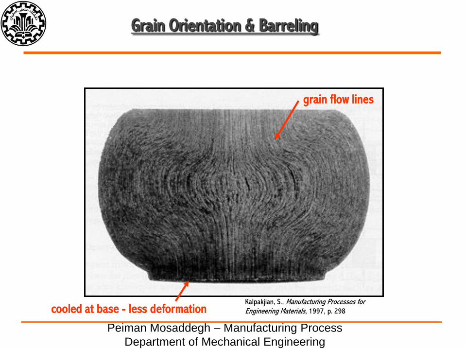
Grain Orientation & Barreling
cooled at base - less deformation
grain flow lines
Kalpakjian, S., Manufacturing Processes for Engineering Materials, 1997, p. 298

Peiman Mosaddegh – Manufacturing Process
Department of Mechanical Engineering
Dead Zones
Areas of no material
deformation

Peiman Mosaddegh – Manufacturing Process
Department of Mechanical Engineering
Upset (Open Die) Forging
Main Types of Forging

Peiman Mosaddegh – Manufacturing Process
Department of Mechanical Engineering
Closed Die - Impression Die Forging
• Dies with inverse shape
of part used
Main Types of Forging
AYKF fp
• Draft angle needed in order
to get part out of mold
• Flash created helps control
“back-pressure” in cavity
• More complex shapes
obtained

Peiman Mosaddegh – Manufacturing Process
Department of Mechanical Engineering
Closed Die - Impression Die Forging • Multiple forging steps or multiple hammer blows
often employed
Main Types of Forging
Kalpakjian, S., Manufacturing Processes for Engineering Materials, 1997, p. 320

Peiman Mosaddegh – Manufacturing Process
Department of Mechanical Engineering
Closed Die - Impression Die Forging
Die for Aircraft Landing Gear
Main Types of Forging
Ostwald, P., Manufacturing Processes & Systems, 1997, p. 331

Peiman Mosaddegh – Manufacturing Process
Department of Mechanical Engineering
Closed Die - Impression Die Forging
Forged Part Terminology
Main Types of Forging
Kalpakjian, S., Manufacturing Processes for Engineering Materials, 1997, p. 320

Peiman Mosaddegh – Manufacturing Process
Department of Mechanical Engineering
Closed Die - Flashless Forging
• Work completely
constrained within die
Main Types of Forging
• Volume of metal must be
controlled closely
• No flash produced
• Best for simple,
symmetric geometries

Peiman Mosaddegh – Manufacturing Process
Department of Mechanical Engineering
Closed Die - Flashless Forging
• Work completely
constrained within die
Main Types of Forging
• Volume of metal must be
controlled closely
• No flash produced
• Best for simple,
symmetric geometries

Peiman Mosaddegh – Manufacturing Process
Department of Mechanical Engineering
Material selection is also important
Forging
Metal or AlloyApproximate Forging
Temperature Range (C)
Aluminum Alloys 400 - 550
Magnesium Alloys 250 - 350
Copper Alloys 600 - 900
Carbon & Low-Alloy Steels 850 - 1150
Martensitic Stainless Steels 1100 - 1250
Austenitic Stainless Steels 1100 - 1250
Titanium Alloys 700 - 950
Iron-base Superalloys 1050 - 1180
Cobalt-base Superalloys 1180 - 1250
Tantalum Alloys 1050 - 1350
Molybdenum Alloys 1150 - 1350
Nickel-base Superalloys 1050 - 1200
Tungsten Alloys 1200 - 1300

Peiman Mosaddegh – Manufacturing Process
Department of Mechanical Engineering
Inspection of Forgings
Inspection Methods
- X-ray
- Ultrasonic
- Must be concerned with defect size and quantity
Can NOT make defect-free forgings…

Peiman Mosaddegh – Manufacturing Process
Department of Mechanical Engineering
Peiman Mosaddegh – Manufacturing Process
Department of Mechanical Engineering
Questions?????