Embed Size (px)
Citation preview
3D Motion Planning for Robot-Assisted Active
Flexible Needle Based on Rapidly-Exploring
Random Trees
Yan-Jiang Zhao Department of Radiation Oncology, Thomas Jefferson University, Philadelphia, PA19107, USA
Intelligent Machine Institute, Harbin University of Science and Technology, Harbin 150080, China
Email: [email protected]; [email protected]
Bardia Konh and Mohammad Honarvar
Department of Mechanical Engineering, Temple University, Philadelphia, PA 19122 USA
Email: {konh, Mohammad.Honarvar}@temple.edu
Felix Orlando Maria Joseph and Tarun K. Podder
Department of Radiation Oncology, Case Western Reserve University, Cleveland, OH 44106 USA
Email: {fom, tarun.podder}@case.edu
Parsaoran Hutapea
Department of Mechanical Engineering, Temple University, Philadelphia, PA 19122 USA
Email: [email protected]
Adam P. Dicker and Yan Yu
Department of Radiation Oncology, Thomas Jefferson University, Philadelphia, PA 19107 USA
Email: {Adam.Dicker, Yan.Yu}@jefferson.edu
Abstract—An active flexible needle is a self-actuating needle
that can bend in the tissue and reach the clinical targets
while avoiding anatomic obstacles. In robot-assisted needle-
based medical procedures, motion planning is a vital aspect
of operations. It is challenging due to the nonholonomic
motion of the needle and the presence of anatomic obstacles
and sensitive organs that must be avoided. We propose a
novel and fast motion planning algorithm for the robot-
assisted active flexible needle. The algorithm is based on
Rapidly-Exploring Random Trees combined with greedy-
heuristic strategy and reachability-guided strategy. Linear
segment and relaxation of insertion orientation are taken
into consideration to the paths. Results show that the
proposed algorithm yields superior results as compared to
the commonly used algorithm in terms of computational
speed, form of path and robustness of searching ability,
which potentially make it suitable for the real-time
intraoperative planning in clinical operations.
Index Terms—active flexible needle, motion planning,
rapidly-exploring random tree, nonholonomic system,
minimally invasive surgery, robot assisted surgery
I. INTRODUCTION
Needle insertion is probably one of the most pervasive procedures in minimally invasive surgeries, such as tissue
Manuscript received August 14, 2014; revised December 2, 2014.
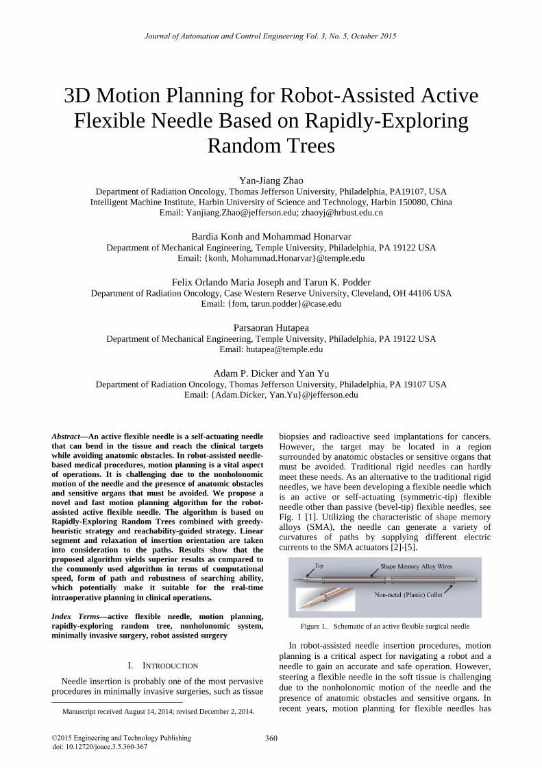
biopsies and radioactive seed implantations for cancers. However, the target may be located in a region surrounded by anatomic obstacles or sensitive organs that must be avoided. Traditional rigid needles can hardly meet these needs. As an alternative to the traditional rigid needles, we have been developing a flexible needle which is an active or self-actuating (symmetric-tip) flexible needle other than passive (bevel-tip) flexible needles, see Fig. 1 [1]. Utilizing the characteristic of shape memory alloys (SMA), the needle can generate a variety of curvatures of paths by supplying different electric currents to the SMA actuators [2]-[5].
Figure 1. Schematic of an active flexible surgical needle
In robot-assisted needle insertion procedures, motion
planning is a critical aspect for navigating a robot and a
needle to gain an accurate and safe operation. However,
steering a flexible needle in the soft tissue is challenging
due to the nonholonomic motion of the needle and the
presence of anatomic obstacles and sensitive organs. In
recent years, motion planning for flexible needles has
Journal of Automation and Control Engineering Vol. 3, No. 5, October 2015
©2015 Engineering and Technology Publishing 360doi: 10.12720/joace.3.5.360-367
been extensively studied in different approaches in 2D
and 3D environments with obstacles [6]-[18].
One popular approach is mathematical computation
method, which formulates the problem as an optimization
problem with an objective function and computes the
optimal solution. Duindam et al. presented a screw-based
motion planning algorithm using an optimizing function
[6], and he also proposed an inverse kinematics motion
planning algorithm based on mathematical calculation [7].
Park et al. proposed a path-of-probability algorithm to
optimize the paths by computing the probability density
function [8]. Alterovitz et al. formulated the path
planning problem of bevel tip flexible needles as a
Markov Decision Process to maximize the probability of
successfully reaching the target in a 2D environment [9].
The mathematical computation method usually has a
computational expense and may suffer from
stability/convergence. Therefore, they are often used for
preoperative planning, but not appropriate for
intraoperative planning.
Another important approach is sampling-based method,
such as the Probabilistic Roadmaps (PRM) or the
Rapidly-Exploring Random Tree (RRT). Alterovitz et al.
proposed a path planner for Markov uncertain motion
base on PRM [10]. Lobaton et al. presented a PRM-based
method for planning paths that visit multiple goals [11].
Since Xu et al. firstly applied RRT-based method to
search a valid needle path in a 3D environment with
obstacles [12], the RRT algorithm is commonly used in
flexible needle path planning. Patil et al. greatly sped up
the calculation utilizing a modified version of RRT
method that combines the reachability guided and goal
bias strategies (RGGB-RRTs) [13], which was then
extended into a dynamic environment replanning [14].
The RGGB-RRTs is the most commonly used algorithm
nowadays. Caborni et al. proposed a risk-based path
planning for a steerable flexible probe based on the
RGGB-RRTs [15]. Recently, Vrooijink et al. proposed a
rapid replanning algorithm based on the RGGB-RRTs,
and embedded it into a control system [16]. Bernardes et
al. presented a fast intraoperative replanning algorithm
based on the RGGB-RRTs in 2D and 3D environments
[17]-[18].
In summary, firstly, all the algorithms are only aiming
at utilizing the curvilinear paths, but not considering the
linear segments, which may both shorten the length of
path and save the cost of control and energy for the active
needle (because you do not have to make the needle bent
by actuators). Although Patil et al. relaxed the curvatures
of the curvilinear paths which allowed the linear
segments in the paths theoretically, because of the
probabilistic nature of the RRT algorithm, the possibility
for the appearance of the linear segment is nearly non-
existent [13]. Secondly, most of the algorithms, if not all,
are with the routine method that the insertion orientation
is fixed or specified, e.g. to be orthogonal to the skin
surface, therefore the planning or optimizing results are
constrained originally. Although Xu et al. relaxed the
insertion orientation by a back-chaining method, the
orientation of approaching to the goal is fixed originally
[12].
In this paper, a novel and fast motion planning
algorithm based on RRT is proposed for the active
flexible needle. We propose a greedy heuristic strategy
using the Depth First Search (DFS) method, and combine
it with the reachablility-guided strategy to improve the
conventional RRT [19]. It is named as Greedy Heuristic
and Reachability-Guided Rapidly-Exploring Random
Trees (GHRG-RRTs). We adopt variable but bounded
curvatures of the needle paths, and we also take account
of linear segments and relaxation of insertion orientations
to the trajectories.
II. KINEMATIC MODEL OF ACTIVE FLEXIBLE NEEDLE
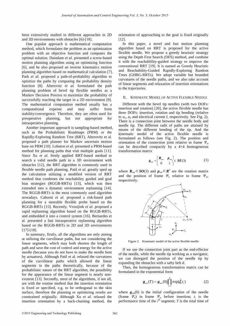
Different with the bevel tip needles (with two DOFs: insertion and rotation) [20], the active flexible needle has three DOFs: insertion, rotation and tip bending (relative to u1, u2 and electrical current I, respectively. See Fig. 2). There is a connection joint between the needle body and needle tip. The different radii of paths are attained by means of the different bending of the tip. And the kinematic model of the active flexible needle is formulated as follows (see Fig. 2). The position and orientation of the connection joint relative to frame Ψw can be described compactly by a 4×4 homogeneous transformation matrix
(3)0 1
wn wn
wn
R pg SE (1)
where Rwn∈SO(3) and pwn∈R3 are the rotation matrix
and the position of frame Ψn relative to frame Ψw,
respectively.
u1
ri
⌒l
u2
I
Xw
Zw
YwѰw
Ѱn
Zn
Xn
Ѱt
Zt
Xt
Ѱp Zp
Xp
θ
d
(ri, 0, 0)
Figure 2. Kinematic model of the active flexible needle
If we use the connection joint part as the end-effector
of the needle, while the needle tip working as a navigator,
we can disregard the position of the needle tip by
expanding the obstacles with a safty belt d.
Then, the homogeneous transformation matrix can be
formulated in the exponential form
1
ˆ( ) (0) exp( )N
wn wn i i
i
T t
g g (2)
where gwn(0) is the initial configuration of the needle
(frame Ψn) in frame Ψw before insertion; ti is the
performance time of the ith
segment; T is the total time of
Journal of Automation and Control Engineering Vol. 3, No. 5, October 2015
©2015 Engineering and Technology Publishing 361
the performance of the whole path, 1
n
i
i
T t
. Details
could be attained in [20].
We coincide frame Ψn and frame Ψw initially, and
consider the insertion pose (rotating β0 around axis Yw
and then rotating α0 around axis Zw), hence, the
configurations of the insertion pose can be obtained by
0 0(0) ( , ) ( , )wn w wRot Z Rot Y g (3)
Since the inputs drive the needle to perform a geometric trajectory, we can encode the trajectory with geometric parameters instead of the actual control inputs U: (u1, u2, I), in order to avoid the inefficient performance that randomly samples control inputs to compute the best combination [12]. The path is composed of a series of segments {C1, C2, . . . , CN} [13], each of which Ci can be parameterized as Ui: (αi, ri, li), where αi is the rotation angle of the needle shaft (corresponding to u2), ri is the radius of the i
th arc (which is infinite if a linear segment,
corresponding to I), and li is the length of the ith
segment (corresponding to u1). The transformation matrix for each segment gi can be formulated by Ui (details are available in Sec. III D).
III. MOTION PLANNING ALGORITHM
The needle motion planning problem is to determine an optimal geometric trajectory using an efficient planner, from which the control plans will be generated so that the needle tip reaches the specified target while avoiding anatomic obstacles. The algorithm can be divided into two parts: one is to generate candidate solutions of paths using a sample-based method, and the other is to find the optimal path based on an objective function. The paths must be complied with the kinematic constraints of the needle. They are smooth and with relaxed but bounded curvatures, including linear segments.
A. Outline of GHRG-RRTs Algorithm
The program is as shown in Algorithm 1. Unlike other RRT algorithms, once initialized with qinit, this algorithm does not immediately generate a random node, instead, it verifies whether a path can be generated directly from qinit to qgoal including linear or curvilinear collision-free path (lines 2-10). If a linear path is achieved, the searching finishes because obviously, it is the best path. If not, it verifies a curvilinear path. And then the algorithm goes into the loop programs. The algorithm begins to generate a random node qrand by the routine RandomNode(). And then it searches for trees and paths in a greedy heuristic way and iterates until the terminate condition is reached. Algorithm 1: GHRG-RRTs (qinit, qgoal, Q)
1: T ← InitTree(qinit); P ← InitPath(qinit); 2: if LinearCheck(qinit, qgoal, Q)
3: U ← SolveLine(qinit, qgoal) 4: P ← AchivePath(T, U, qgoal)
5: return P
6: end if
7: U ← SolveSeg(T.ginit, qgoal)
8: if U.r ≥ rmin & CollisionFree(U, Q) 9: P ← AchivePath(T, U, qgoal)
10: end if
11: while (n < max_path) & (i < max_iteration)
12: qrand ← RandomNode(); flag ← false
13: if LinearCheck(qinit, qrand) 14: U ← SolveLine(qinit, qrand)
15: T ← ExtendTree (T, U, qrand) 16: U← SolveSeg(T.grand, qgoal)
17: if U.r ≥ rmin & CollisionFree(U, Q)
18: P ← AchievePath (T, U, qgoal); flag ← true 19: end if
20: end if
21: U← SolveSeg(qinit, qrand)
22: if U.r ≥ rmin & CollisionFree(U, Q)
23: T ← ExtendTree (T, U, qrand) 24: end if
25: U←SolveSeg(T.grand, qgoal) 26: if U.r ≥ rmin & CollisionFree(U, Q)
27: P ← AchievePath (T, U, qgoal); flag ← true
28: end if
29: if flag==false
30: qproper ← FindProperNode (T, qrand, ρ) 31: U ←SolveSeg(T.gproper, qrand)
32: if U.r ≥ rmin & CollisionFree(U, Q)
33: T ← ExtendTree (T, U, qrand) 34: U ← SolveSeg(T.grand, qgoal)
35: if U.r ≥ rmin & CollisionFree(U, Q) 36: P ← AchievePath (T, U, qgoal)
37: end if
38: end if
39: end while
40: popt ← Optimization(P) 41: return popt
AchievePath (T, U, qgoal)
1: T ←ExtendTree (T, U, qgoal) 2: p ← ExtractPath(T)
3: P.add_path(p) 4: return P
ExtendTree (T, U, q)
1: g ← GetConfig(U, q) 2: T. add_vertex(q)
3: T. add_edge(q, g) 4: return T
B. Greedy-Heuristic Strategy
In contrast to all the previous RRT algorithms, we
propose a greedy heuristic strategy to generate more trees
and complete more paths: on the one hand, it is greedy
for initial node to generate a new tree; on the other hand,
it is greedy for the goal node to achieve a path. After a
valid random node is obtained, the algorithm will verify
whether a linear segment could be generated connecting
the initial node qinit to the random node qrand, if yes, a new
tree starting with a linear segment will be generated (lines
13-15). By doing so, it successfully relaxes the insertion
orientations, which can be in various angles rather than
just orthogonal to the skin surface. If the tree is generated,
it goes on to verify whether qrand can connect qgoal (lines
16-19), if yes, a new path will be gained. Here we are
greedy for searching the goal, because we believe that the
direct connection from qrand to qgoal is probabilistically
superior to those which travel round and then connect to
the goal. This strategy is also with an idea of DFS to
effectively achieve goals. Then it will search for a
curvilinear path with the similar process (lines 21-28). If
no path is gained after above searching, it will try to
extend the other trees that have not been achieved a path
(line 29-33). In contrast to searching for a nearest node in
the previous algorithms, it searches for a proper node
qproper (by routine 30). The proper node should be amid all
the nodes but for the initial node qinit and the goal node
qgoal in all trees that have not been achieved a path. The
Get a linear path
Get a curve path
Get a linear tree
Get a path
Get a curve tree
Get a path
Extend a tree
Get a path
Journal of Automation and Control Engineering Vol. 3, No. 5, October 2015
©2015 Engineering and Technology Publishing 362
idea of the proper node means the node should not be too
near to an existing node, the distance should be larger
than a specific metric ρ in order to prevent the
insufficient growth. It is the nearest node in those whose
distances to qrand are larger than ρ. After qproper is acquired,
from which the algorithm will extend the tree to qrand,
then try to achieve a path by similar means (lines 21-28).
C. Reachability-Guided Strategy
-500
50
-500
50
0
20
40
60
80
100
y(mm)x(mm)
z(m
m)
(a) Reachable region in 3D
BA
needle
reachable region
qi-1
rmin rmin
Ψn Xn
Zn
ΨwXw
Zw
qi
(b) Reachable region in 2D
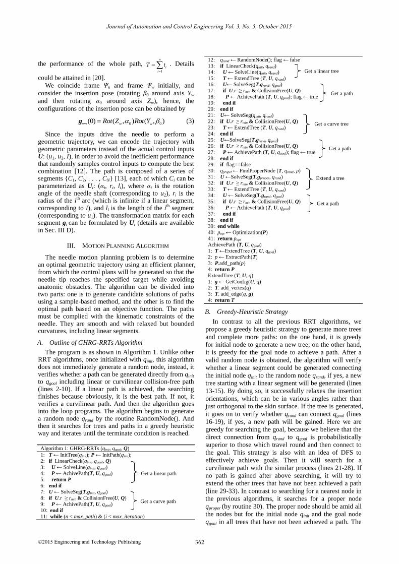
Figure 3. Reachable Region of the Needle
The path is composed of a series of segments, each of
which the final extremity corresponds to the next
segment’s initial extremity, not only in position but also
in orientation, because of the presence of the
nonholonomic constraints. Hence, it is possible that a
node is not reachable for a specific extremity (with a
specific configuration). The reachable region of the
needle is a mushroom-like area as shown in Fig. 3(a). In
order to elaborate the problem, we project it into 2D
(XOZ plane), which is a leaf-like area as shown in Fig.
3(b). From qi-1 in a local frame Ψn, the reachable region
will extend with the depth of insertion, but no matter how
deeply it is inserted, there always are two regions of A
and B that cannot be reached. There is a minimum
bending radius rmin for the needle path corresponding to
the mechanical properties of the needle. In order to speed
up the search and make the following calculation
effective, the reachability of the next node qi (may be qgoal
or qrand) should be checked. According to the Fig. 3, the
next node is reachable as long as
i minr r (4)
where ri is the radius of the ith
segment (from qi-1 to qi),
one of the input parameters, and can be obtained in the
next section; rmin is the minimum radius constraint of the
needle path.
Different from the reachability-guided strategy
proposed in [13], we directly use one of the input
parameters as a judgment, instead of bringing in extra
calculations, which is beneficial for speeding up the
search [18].
D. Input Parameter U and Configurationg
Because we have considered the insertion pose, there
are two additional parameters before insertion: α0 and β0
as mentioned in Sec. 2. For a path starting with a
curvilinear segment, they are generated randomly by the
planner; for a linear path or a path starting with a linear
segment, they are obtained by (5-6). And then the
insertion pose gwn(0) is calculated by (4).
0
arctan( / ), 0
arctan( / ), 0
n n
n n
y x x
y x x
(5)
0 arctan( / )nk z (6)
where xn, yn, zn are the coordinates of the next node qi in
frame Ψn, which is initially coincided with frame Ψw;
2 2
n nk x y .
ri
⌒l
xn
Ѱnqi-1
ϕi
zn
yn
qi: (xi; yi; zi)
αi
Zn
Yn
Xn
Ѱw
Xw
Zw
Yw
Figure 4. Input of the ith segment
Assume that the extremity qi of the ith
segment is with
an input Ui operating from qi-1, and is with a subsequent
transformation matrix gi in the form as (1). A local frame
Ψn is attached to qi-1 as is shown in Fig. 4. The
coordinates of qi: (xi; yi; zi) in frame Ψw are converted into
frame Ψn as qi: (xn; yn; zn), ϕi is the angle embraced by the
circular arc. So the input Ui: (αi, ri, li) can be formulated
as follows:
2/ 2 / 2i nr k z k (7)
2arctan( / )i nz k (8)
i i il r (9)
The input αi can be calculated by (5), and the
transformation matrix gi obtained by
Journal of Automation and Control Engineering Vol. 3, No. 5, October 2015
©2015 Engineering and Technology Publishing 363
cos cos sin cos sin
sin cos cos sin sin
sin 0 cos
0 0 0 1
i i i i i n
i i i i i n
i
i i n
x
y
z
g (10)
The configuration of the end-effector gwn can be
obtained by (2).
E. Optimization Function
Among the candidate solutions, all of which have
already met the required constraints, the optimal path can
be chosen based on a cost function. The objectives of the
optimization will take consideration of minimizing the
tissue trauma, enhancing the accuracy, and minimizing
the force-torque on the needle as well as the temperature
rise.
1 2 3 4min ( , ) min{ }F T L D S N u (11)
where L is the length of the path; D is the degree of
danger in the path, relative to the distance between the
path and the obstacles; S is the curve valuation of the path,
evaluated by curvatures, which is relative to the force-
torque on the needle as well as the temperature rise; N is
the degree of control, i.e. the number of segments of the
whole path, which is relative to the control cost and
accuracy [21]; α1~α4 are the weighted coefficients. The
result of the function is the comprehensive evaluation of
the optimal path.
IV. SIMULATION RESULTS AND DISCUSSION
We simulated the motion planner in MATLAB® (ver.
7.8.0, R2009a; MathWorks, Natick, MA) on a 2.5 GHz 4-
core Intel® i5™ PC. We firslty set the minmum radius
rmin=50mm [13], [22], the specific metric ρ=10mm. The
maximum number of the candidate paths is set to 100,
and the maximum number of iterations to 10000.
Assuming that the obstacle is containing a relative belt of
safe margin around it, in order to speed up the
computation, we can disregard the second term in (11) by
setting α2=0. The weighted coefficients α1=α3=α4=1. In
order to compare the performances of the GHRG-RRTs
algorithm and the RGGB-RRTs algorithm, we set the
goal bias factor to 0.2 as in [15].
A. Test Case 1
-100
-50
0
50
100
-100
-50
0
50
100
0
50
100
150
200
x(mm)
Path Planning for the Active Needle Based on GHRG-RRTs
start
goal
y(mm)
z(m
m)
(a) GHRG-RRTs algorithm
-100
-50
0
50
100
-100
-50
0
50
100
0
50
100
150
200
x(mm)
Path Planning for the Active Needle Based on RGGB-RRTs
start
goal
y(mm)
z(m
m)
(b) RGGB-RRTs algorithm
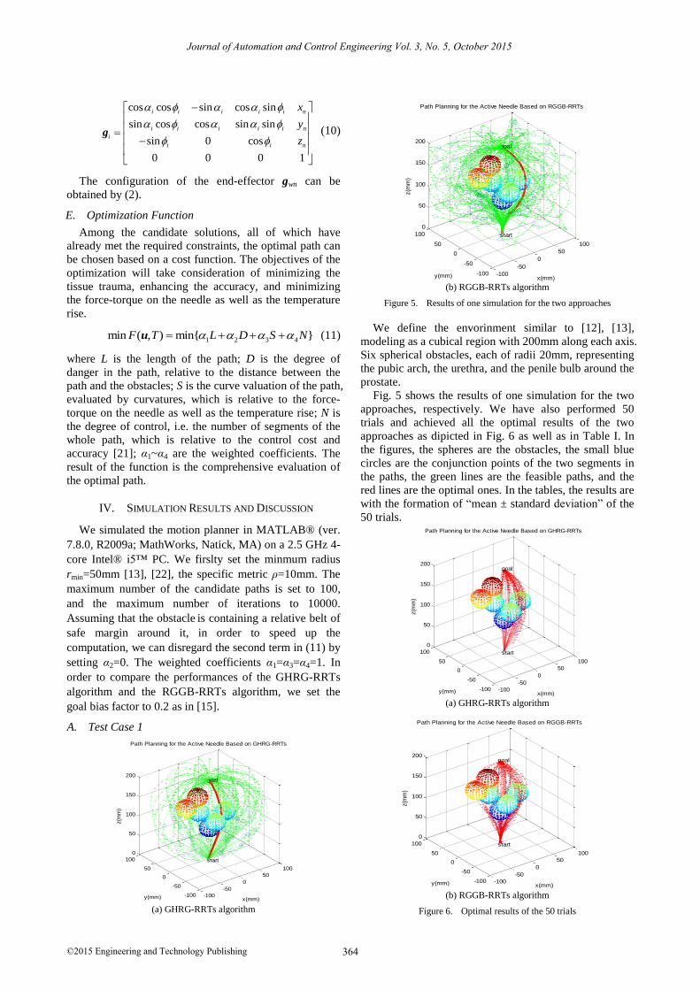
Figure 5. Results of one simulation for the two approaches
We define the envorinment similar to [12], [13],
modeling as a cubical region with 200mm along each axis.
Six spherical obstacles, each of radii 20mm, representing
the pubic arch, the urethra, and the penile bulb around the
prostate.
Fig. 5 shows the results of one simulation for the two
approaches, respectively. We have also performed 50
trials and achieved all the optimal results of the two
approaches as dipicted in Fig. 6 as well as in Table I. In
the figures, the spheres are the obstacles, the small blue
circles are the conjunction points of the two segments in
the paths, the green lines are the feasible paths, and the
red lines are the optimal ones. In the tables, the results are
with the formation of “mean ± standard deviation” of the
50 trials.
-100
-50
0
50
100
-100
-50
0
50
100
0
50
100
150
200
x(mm)
Path Planning for the Active Needle Based on GHRG-RRTs
start
goal
y(mm)
z(m
m)
(a) GHRG-RRTs algorithm
-100
-50
0
50
100
-100
-50
0
50
100
0
50
100
150
200
x(mm)
Path Planning for the Active Needle Based on RGGB-RRTs
start
goal
y(mm)
z(m
m)
(b) RGGB-RRTs algorithm
Figure 6. Optimal results of the 50 trials
Journal of Automation and Control Engineering Vol. 3, No. 5, October 2015
©2015 Engineering and Technology Publishing 364
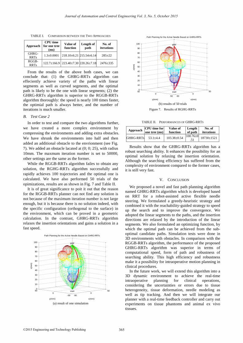
TABLE I. COMPARISON BETWEEN THE TWO APPROACHES
Approach
CPU time
for one tree
(ms)
Value of
function
Length of
path
No. of
iterations
GHRG-RRTs
1.3±0.0001 218.10±6.21 215.54±6.14 285±22
RGGB-
RRTs 122.7±166.9 223.40±7.30 220.26±7.18 2476±335
From the results of the above both cases, we can
conclude that: (1) the GHRG-RRTs algorithm can
effeciently achieve variety of the paths with linear
segments as well as curved segments, and the optimal
path is likely to be the one with linear segments; (2) the
GHRG-RRTs algorithm is superior to the RGGB-RRTs
algorithm thoroughly: the speed is nearly 100 times faster,
the optimial path is always better, and the number of
iterations is much smaller.
B. Test Case 2
In order to test and compare the two algorithms further,
we have created a more complex environment by
compressing the environments and adding extra obstacles.
We have shrunk the environments into half and then
added an additional obstacle to the envrionment (see Fig.
7). We added an obstacle lacated at (0; 0; 25), with radius
10mm. The maxmum iteration number is set to 50000,
other settings are the same as the former.
While the RGGB-RRTs algorithm failes to obtain any
solution, the RGHG-RRTs algorithm successfully and
rapidly achieves 100 trajectories and the optimal one is
calculated. We have also performed 50 trials of the
opimizations, results are as shown in Fig. 7 and Table II.
It is of great significance to poit it out that the reason
for the RGGB-RRTs planner can not find any solution is
not because of the maximum iteration number is not large
enough, but it is because there is no solution indeed, with
the specific configuration (orthogonal to the surface) in
the environment, which can be proved in a geometric
calculation. In the contrast, GHRG-RRTs algorithm
relaxes the insertion orientations and gains a solution in a
fast speed.
-500
50
-500
500
10
20
30
40
50
60
70
80
90
100
x(mm)
Path Planning for the Active Needle Based on GHRG-RRTs
goal
start
y(mm)
z(m
m)
(a) result of one simulation
-500
50
-500
500
10
20
30
40
50
60
70
80
90
100
x(mm)
Path Planning for the Active Needle Based on GHRG-RRTs
start
goal
y(mm)
z(m
m)
(b) results of 50 trials
Figure 7. Results of RGHG-RRTs
TABLE II. PERFORMANCES OF GHRG-RRTS
Approach CPU time for
one tree (ms)
Value of
function
Length
of path
No. of
iterations
GHRG-RRTs 53.1±4.4 103.38±0.54 100.76±0
.51 18730±1521
Results show that the GHRG-RRTs algorithm has a
robust searching ability. It enhances the possibility for an
optimal solution by relaxing the insertion orientation.
Although the searching efficiency has suffered from the
complexity of environment compared to the former cases,
it is still very fast.
V. CONCLUSION
We proposed a novel and fast path planning algorithm
named GHRG-RRTs algorithm which is developed based
on RRT for a robot-assisted active flexible needle
steering. We formulated a greedy-heuristic strategy and
combined it with the reachability-guided strategy to speed
up the search and to improve the convergence. We
adopted the linear segments to the paths, and the insertion
directions are relaxed by the introduction of the linear
segments. We also formulated an optimizing function, by
which the optimal path can be achieved from the sub-
optimal candidate paths. Simulation tests were done in
3D environments with obstacles. In comparison with the
RGGB-RRTs algorithm, the performance of the proposed
GHRG-RRTs algorithm was superior in terms of
computational speed, form of path and robustness of
searching ability. This high efficiency and robustness
make it a possibility for intraoperative motion planning in
clinical procedures.
In the future work, we will extend this algorithm into a
3D dynamic environment to achieve the real-time
intraoperative planning for clinical operations,
considering the uncertainties or errors due to tissue
heterogeneity, tissue deformation, needle modeling as
well as tip tracking. And then we will integrate our
planner with a real-time feedback controller and carry out
experiments on tissue phantoms and animal ex vivo
tissues.
Journal of Automation and Control Engineering Vol. 3, No. 5, October 2015
©2015 Engineering and Technology Publishing 365
ACKNOWLEDGMENT
This research is supported in part by the Department of
Defense CDMRP Prostate Cancer Research Program
(Grants# W81XWH-11-1-0397/98/99), by National
Natural Science Foundation of China (Grant# 51305107)
and by Science and Technology Project of Heilongjiang
Provincial Education Department, China (Grant#
12531110).
REFERENCES
[1] T. K. Podder, A. P. Dicker, P. Hutapea, K. Darvish, and Y. Yu, “A
novel curvilinear approach for prostate seed implantation,” Med.
Phys., vol. 39, no. 4, pp. 1887-1892, Apr. 2012.
[2] N. V. Datla, M. Honarvar, T. M. Nguyen, B. Konh, K. Darvish, Y.
Yu, et al., “Toward a nitinol actuator for an active surgical
needle,” in Proc. ASME Conference on Smart Material, Adaptive Structures and Intelligent Systems, 2012, pp. 19-21.
[3] B. Konh, N. V. Datla, M. Honarvar, T. K. Podder, A. P. Dicker, Y. Yu, and P. Hutapea, “Design exploration study of a shape memory
alloy actuated surgical needle,” Journal of Intelligent Material
Systems and Structures, in press. [4] M. Honarvar, N. V. Datla, B. Konh, T. K. Podder, A. P. Dicker, Y.
Yu, and P. Hutapea, “Study of unrecovered strain and critical stresses in one-way shape memory nitinol,” Journal of Materials
Engineering and Performance, in press.
[5] B. Konh, M. Honarvar, and P. Hutapea, “Application of SMA wire for an active steerable cannula,” in Proc. ASME Conference
on Smart Materials, Adaptive Structures and Intelligent Systems, 2013, pp. 265-269.
[6] V. Duindam, R. Alterovitz, S. Sastry, and K. Goldberg, “Screw-
based motion planning for bevel-tip flexible needles in 3D
environments with obstacles,” in Proc. IEEE Int. Conf. on
Robotics and Automation, 2008, pp. 2483-2488. [7] V. Duindam, J. Xu, R. Alterovitz, S. Sastry, and K. Goldberg,
“Three-dimensional motion planning algorithms for steerable
needles using inverse kinematics,” Int. Journal of Robotics Research, vol. 29, no. 7, pp. 789-800, June 2010.
[8] W. Park, Y. Wang, and G. S. Chirikjian, “The path-of-probability algorithm for steering and feedback control of flexible needles,”
Int. Journal of Robotics Research, vol. 29, no. 7, pp. 813-830,
June 2010. [9] R. Alterovitz, M. Branicky, and K. Goldberg, “Motion planning
under uncertainty for image-guided medical needle steering,” Int. Journal of Robotics Research, vol. 27, no. 11-12, pp. 1361-1374,
Nov./Dec. 2008.
[10] R. Alterovitz, S. Patil, and A. Derbakova, “Rapidly-exploring Roadmaps: Weighing exploration vs. refinement in optimal
motion planning,” in Proc. IEEE Int. Conf. on Robotics and Automation, 2011, pp. 3706-3716.
[11] E. Lobaton, J. Zhang, S. Patil, and R. Alterovitz, “Planning
curvature-constrained paths to multiple goals using circle sampling,” in Proc. IEEE Int. Conf. on Robotics and Automation,
2011, pp. 1463-1469. [12] J. Xu, V. Duindam, and K. Goldberg, “Motion planning for
steerable needles in 3D environments with obstacles using rapidly
exploring random trees and backchaining,” in Proc. IEEE Int. Conf. on Automation Science and Engineering, 2008, pp. 41-46.
[13] S. Patil and R. Alterovitz, “Interactive motion planning for steerable needles in 3D environments with obstacles,” in Proc.
IEEE RAS/EMBS Int. Conf. Biomedical Robotics and
Biomechatronics, 2010, pp. 893-899. [14] S. Patil, J. Burgner, R. J. Webster III, and R. Alterovitz, “Needle
steering in 3-D via rapid replanning,” IEEE Trans. on Robotics, in press.
[15] C. Caborni, S. Y. Ko, E. D. Momi, G. Ferrigno, and F. R. Y.
Baena, “Risk-based path planning for a steerable flexible probe for neurosurgical intervention,” in Proc. IEEE RAS/EMBS Int. Conf.
on Biomedical Robotics and Biomechatronics, 2012, pp. 866-871. [16] G. J. Vrooijink, M. Abayazid, S. Patil, R. Alterovitz, and S. Misra,
“Needle path planning and steering in a three-dimensional non-
static environment using two-dimensional ultrasound images,” Int. Journal of Robotics Research, in press.
[17] M. C. Bernardes, B. V. Adorno, P. Poignet, and G. A. Borges, “Robot-assisted automatic insertion of steerable needles with
closed-loop imaging feedback and intraoperative trajectory
replanning,” Mechatronics, vol. 23, no. 6, pp. 630-645, Sep. 2013. [18] M. C. Bernardes, B. V. Adorno, G. A. Borges, and P. Poignet, “3D
robust online motion planning for steerable needles in dynamic workspaces using duty-cycled rotation,” Journal of Control,
Automation and Electrical Systems, vol. 25, no. 2, pp. 216-227,
Apr. 2014. [19] S. M. LaValle and J. J. Kuffner, “Randomized kinodynamic
planning,” Int. Journal of Robotics Research, vol. 20, no. 5, pp. 378-400, May 2001.
[20] R. J. Webster III, J. S. Kim, N. J. Cowan, G. S. Chirikjian, and A.
M. Okamura, “Nonholonomic modeling of needle steering,” Int. Journal of Robotics Research, vol. 25, no. 5–6, pp. 509–525, May
2006. [21] K. B. Reed, A. M. Okamura, and N. J. Cowan, “Controlling a
robotically steered needle in the presence of torsional friction,” in
Proc. IEEE International Conference on Robotics and Automation, 2009, pp. 3476-3481.
[22] Y. J. Zhao, Y. D. Zhang, and J. P. Shao, “Kinematic modeling and experimental study of flexible needle,” Robot, vol. 32, no. 5, pp.
666-673, Sep. 2010.
Yan-Jiang Zhao, born in Harbin, China, Nov. 23, 1979, received his B. Sc. degree in
Mechanical Engineering from Heilongjiang
University of Science and Technology, Harbin, China, in 2003, and his M.Sc. degree
in Mechanical and Electrical Engineering, Ph.D. degree in Mechanical Engineering
from Harbin University of Science and
Technology, Harbin, China, in 2006 and 2012, respectively. Since 2013, he has been a
Postdoctoral Research Fellow in the Department of Radiation Oncology, Thomas Jefferson University, Philadelphia, PA, USA. He is currently
also an Associated Professor and a Master Tutor in Mechanical and
Electrical Engineering of Intelligent Machine Institute, Harbin University of Science and Technology, Harbin, China. His main
research interest is medical robotics.
Bardia Konh received his B. S. in 2007 from K. N. Toosi University of Technology and M.
Sc. in 2011 from Free University of Science and Research in Tehran, Iran. He is currently
a Ph. D. Candidate in the Department of
Mechanical Engineering of Temple University in Philadelphia, PA, USA. His
research interest is in the design of medical devices using active/smart materials.
Mohammad Honarvar received his B. Sc.
and M. Sc. in material science and engineering from Shiraz University, Shiraz,
Iran. He is currently a Ph. D. candidate in the
Department of Mechanical Engineering of Temple University. His research focus is on
the investigation of thermomechanical behavior of Nitinol for actuators in
biomedical devices.
Felix Orlando Maria Joseph received his B. E. degree in Instrumentation and Control
Engineering from Madras University, M. E.
degree in Robotics and HCI from KIST South Korea, Ph. D. in Electrical Engineering from
IIT Kanpur, India. Since Feb. 2014, is a Post-
Doctoral Research Fellow in the department
of Radiation Oncology, University Hospitals,
Case Western Reserve University, Cleveland, OH, USA.
Journal of Automation and Control Engineering Vol. 3, No. 5, October 2015
©2015 Engineering and Technology Publishing 366
Tarun Podder received the B. E. degree from the University of Calcutta, Kolkata,
India, in 1988, and M.E. degree from the
Indian Institute of Science, Bangalore, India, in 1990, both in Mechanical Engineering, and
t h e Ph . D. d eg r ee i n R ob ot i c s an d Automation from the University of Hawaii,
Manoa, in 2000. From 2001 to 2006, he was
with Rochester Institute of Technology, R. Systems, Inc., Monterey Bay Aquarium
Research Institute, and the University of Rochester as a Research Scientist, Research Specialist and Project
Manager, Research Fellow, and Research Assistant Professor,
respectively. From 2006 to 2012, he was with the Thomas Jefferson University, the University of North Carolina, and East Carolina
University as an Assistant Professor, Adjunct Associate Professor and Associate Professor, respectively. Currently, he is an Associate
Professor in Department of Radiation Oncology, Case Western Reserve
University, Cleveland, OH. His current research interests include dynamics, path planning, and control of robotic and autonomous
systems, especially medical robotics and devices. Dr. Podder is a member of the Institute of Electrical and Electronics Engineers, the
American Society of Mechanical Engineers, the IEEE Engineering in
Medicine and Biology Society, the IEEE Robotics and Automation Society, the American Association of Physicists in Medicine, and the
American Society for Therapeutic Radiology and Oncology.
Parsaoran Hutapea received his B. Sc, M. Sc, and Ph. D. in Aerospace Engineering, all
from North Carolina State University,
Raleigh, North Carolina.
He
is currently an
Associate Professor in the Department of
Mechanical Engineering of Temple University in Philadelphia, PA, USA. He
is
the Directors of Composites Laboratory and
the College of Engineering Nano Instrumentation Center.
Adam P. Dicker received his B.A. in
Chemistry from Columbia College, New
York, NY, in
1984, Ph. D. in Molecular
Pharmacology and Therapeutics from Cornell University Graduate School of Medical
Sciences, New York, NY, in 1991, and M. D. in Medicine from Cornell University Medical
College, New York, NY
in
1992.
He
is the
Chair & Professor of Radiation Oncology, Thomas Jefferson University, Philadelphia,
PA. He serves as Director, Christine Baxter Research Laboratory for Experimental Cancer Therapies at Jefferson Medical College. He
coordinates an interdisciplinary team of oncologists, physicists and
scientists focused on multidisciplinary effort to define fundamental mechanisms and targets for combined modality radiation treatment and
efficiently translate them to effective innovations in treating cancer patients. He serves as the Chair of the Translational Research Program
in the Radiation Therapy Oncology Group (RTOG). He has published
numerous papers evaluating signal transduction agents with ionizing radiation and published “first
in
human” developmental therapeutic
trials involving novel signal transduction agents and radiation therapy. Dr. Dicker served as Chair of the Radiation and Cancer Biology
Committee of the American Society of Therapeutic Radiation Oncology,
and currently is Chairperson of the Radiation Oncology Section of the Clinical Research Subcommittee of AACR. Dr. Dicker serves as the co-
Chair-Translational Science Committee for the NCI cooperative group. Dr. Dicker was recently appointed as a member of the Integration Panel
for the Prostate Cancer Research Program of the Department of Defense
Prostate Cancer Research Program.
Yan Yu
received his B. Sc. degree from Queen
Mary College and Ph. D. degree from
University College, both of University of
London, UK, in Physics, in 1983 and 1986,
respectively. He also received an MBA degree from University of Rochester, Rochester, NY,
USA, in 1998. After completing a clinical
fellowship in medical physics, he was on the faculty of the University of Rochester Medical
Center from 1994 to 2006. He
is currently a Vice Chair, Professor and Director of Medical Physics in the
Department of Radiation Oncology, Thomas Jefferson University,
Philadelphia, PA, USA. Prof. Yu
is a member of the American Association of Physicists in Medicine, the Radiation Research Society,
the American Society for Therapeutic Radiology and Oncology, the American Brachytherapy Society, the American Board of Surgery, the
American College of Radiology, the Institute of Physics and
Engineering in Medicine (Overseas Affiliate member), and Sino-American Network for Therapeutic Radiology and Oncology.
Journal of Automation and Control Engineering Vol. 3, No. 5, October 2015
©2015 Engineering and Technology Publishing 367


![Robot-Assisted Wedge-Bronchoplastic Right Upper … · Robot-Assisted Wedge-Bronchoplastic Right Upper ... 4-6]. Despite lack of supporting data, Park SY et al ... (2017) Robot-Assisted](https://img.pdfslide.us/doc/110x75/5b78e7b67f8b9a331e8c927a/robot-assisted-wedge-bronchoplastic-right-upper-robot-assisted-wedge-bronchoplastic.jpg)