Embed Size (px)
Citation preview
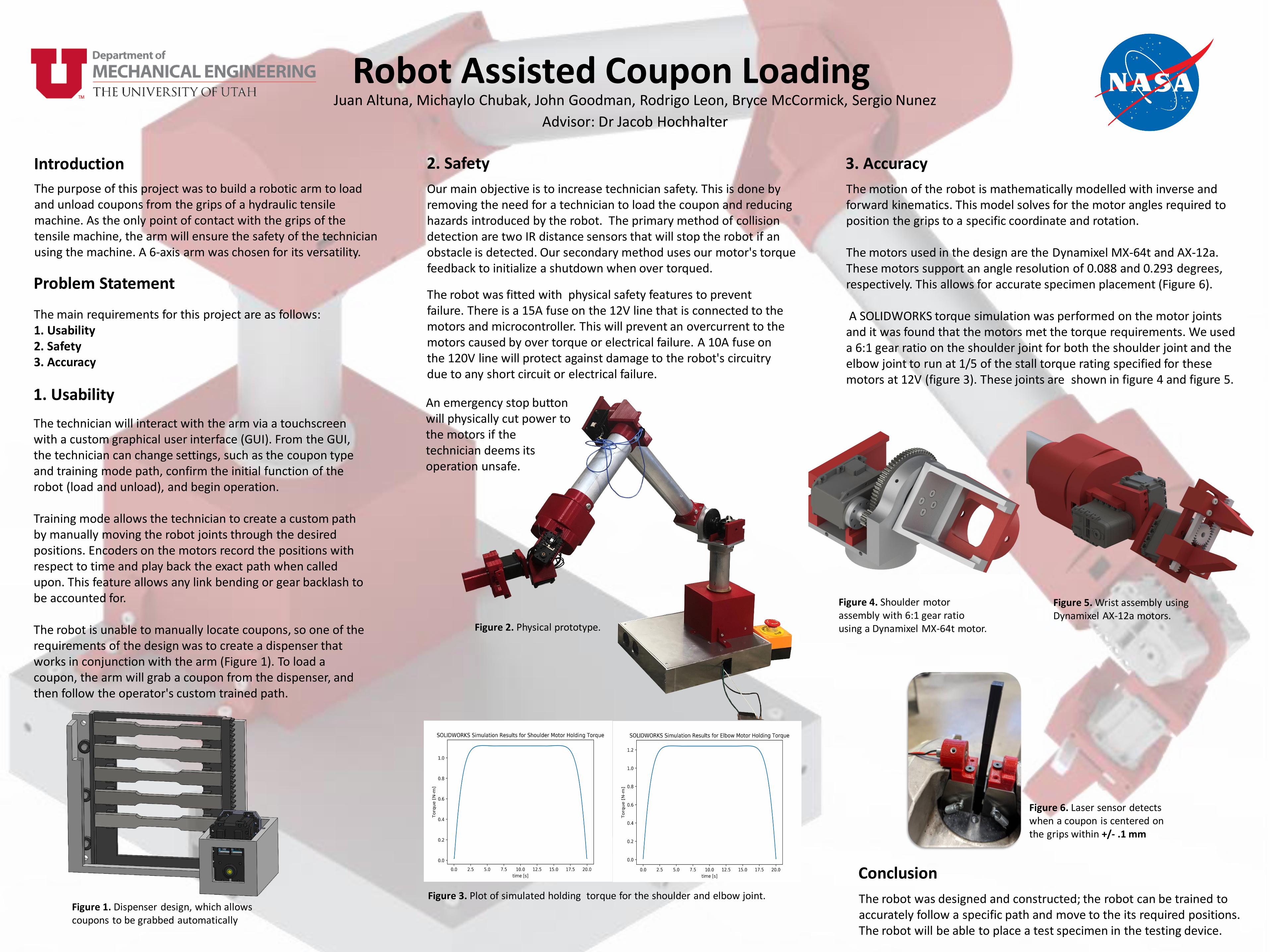
Juan Altuna, Michaylo Chubak, John Goodman, Rodrigo Leon, Bryce McCormick, Sergio Nunez
Advisor: Dr Jacob Hochhalter
Robot Assisted Coupon Loading
Introduction
Problem Statement
Conclusion
The purpose of this project was to build a robotic arm to load and unload coupons from the grips of a hydraulic tensile machine. As the only point of contact with the grips of the tensile machine, the arm will ensure the safety of the technician using the machine. A 6-axis arm was chosen for its versatility.
3. Accuracy
1. Usability
The main requirements for this project are as follows:1. Usability2. Safety3. Accuracy
2. Safety
The motion of the robot is mathematically modelled with inverse and forward kinematics. This model solves for the motor angles required to position the grips to a specific coordinate and rotation.
The motors used in the design are the Dynamixel MX-64t and AX-12a. These motors support an angle resolution of 0.088 and 0.293 degrees, respectively. This allows for accurate specimen placement (Figure 6).
A SOLIDWORKS torque simulation was performed on the motor joints and it was found that the motors met the torque requirements. We used a 6:1 gear ratio on the shoulder joint for both the shoulder joint and the elbow joint to run at 1/5 of the stall torque rating specified for these motors at 12V (figure 3). These joints are shown in figure 4 and figure 5.
The technician will interact with the arm via a touchscreen with a custom graphical user interface (GUI). From the GUI, the technician can change settings, such as the coupon type and training mode path, confirm the initial function of the robot (load and unload), and begin operation.
Training mode allows the technician to create a custom path by manually moving the robot joints through the desired positions. Encoders on the motors record the positions with respect to time and play back the exact path when called upon. This feature allows any link bending or gear backlash to be accounted for.
The robot is unable to manually locate coupons, so one of the requirements of the design was to create a dispenser that works in conjunction with the arm (Figure 1). To load a coupon, the arm will grab a coupon from the dispenser, and then follow the operator's custom trained path.
Our main objective is to increase technician safety. This is done by removing the need for a technician to load the coupon and reducing hazards introduced by the robot. The primary method of collision detection are two IR distance sensors that will stop the robot if an obstacle is detected. Our secondary method uses our motor's torque feedback to initialize a shutdown when over torqued.
The robot was designed and constructed; the robot can be trained to accurately follow a specific path and move to the its required positions. The robot will be able to place a test specimen in the testing device.
Figure 3. Plot of simulated holding torque for the shoulder and elbow joint.
Figure 6. Laser sensor detects when a coupon is centered on the grips within +/- .1 mm
Figure 1. Dispenser design, which allowscoupons to be grabbed automatically
Figure 2. Physical prototype.
The robot was fitted with physical safety features to prevent failure. There is a 15A fuse on the 12V line that is connected to the motors and microcontroller. This will prevent an overcurrent to the motors caused by over torque or electrical failure. A 10A fuse on the 120V line will protect against damage to the robot's circuitry due to any short circuit or electrical failure.
An emergency stop button will physically cut power to the motors if the technician deems its operation unsafe.
Figure 4. Shoulder motor assembly with 6:1 gear ratio using a Dynamixel MX-64t motor.
Figure 5. Wrist assembly using Dynamixel AX-12a motors.