Embed Size (px)
Citation preview
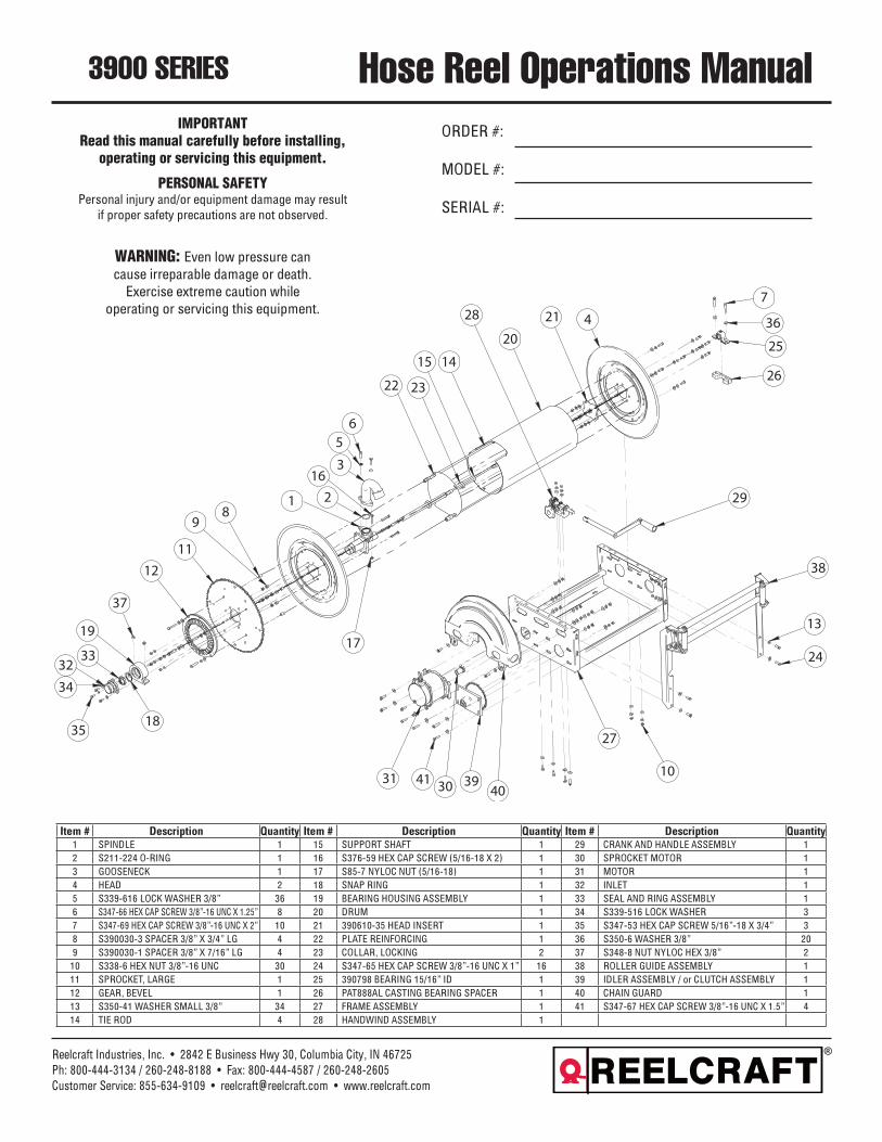
Hose Reel Operations ManualORDER #:
MODEL #:
SERIAL #:
3900 SERIES
Reelcraft Industries, Inc. • 2842 E Business Hwy 30, Columbia City, IN 46725Ph: 800-444-3134 / 260-248-8188 • Fax: 800-444-4587 / 260-248-2605Customer Service: 855-634-9109 • [email protected] • www.reelcraft.com
Item # Description Quantity Item # Description Quantity Item # Description Quantity1 SPINDLE 1 15 SUPPORT SHAFT 1 29 CRANK AND HANDLE ASSEMBLY 12 S211-224 O-RING 1 16 S376-59 HEX CAP SCREW (5/16-18 X 2) 1 30 SPROCKET MOTOR 13 GOOSENECK 1 17 S85-7 NYLOC NUT (5/16-18) 1 31 MOTOR 14 HEAD 2 18 SNAP RING 1 32 INLET 15 S339-616 LOCK WASHER 3/8” 36 19 BEARING HOUSING ASSEMBLY 1 33 SEAL AND RING ASSEMBLY 16 S347-66 HEX CAP SCREW 3/8”-16 UNC X 1.25” 8 20 DRUM 1 34 S339-516 LOCK WASHER 37 S347-69 HEX CAP SCREW 3/8”-16 UNC X 2” 10 21 390610-35 HEAD INSERT 1 35 S347-53 HEX CAP SCREW 5/16”-18 X 3/4” 38 S390030-3 SPACER 3/8” X 3/4” LG 4 22 PLATE REINFORCING 1 36 S350-6 WASHER 3/8” 209 S390030-1 SPACER 3/8” X 7/16” LG 4 23 COLLAR, LOCKING 2 37 S348-8 NUT NYLOC HEX 3/8” 2
10 S338-6 HEX NUT 3/8”-16 UNC 30 24 S347-65 HEX CAP SCREW 3/8”-16 UNC X 1” 16 38 ROLLER GUIDE ASSEMBLY 111 SPROCKET, LARGE 1 25 390798 BEARING 15/16” ID 1 39 IDLER ASSEMBLY / or CLUTCH ASSEMBLY 112 GEAR, BEVEL 1 26 PAT888AL CASTING BEARING SPACER 1 40 CHAIN GUARD 113 S350-41 WASHER SMALL 3/8” 34 27 FRAME ASSEMBLY 1 41 S347-67 HEX CAP SCREW 3/8”-16 UNC X 1.5” 414 TIE ROD 4 28 HANDWIND ASSEMBLY 1
IMPORTANTRead this manual carefully before installing,
operating or servicing this equipment.
PERSONAL SAFETYPersonal injury and/or equipment damage may result
if proper safety precautions are not observed.
WARNING: Even low pressure can cause irreparable damage or death.
Exercise extreme caution while operating or servicing this equipment.
PRE-INSPECTION1. Check reel for shipping damages.2. Insured all parts are supplied as ordered.3. Record model number and serial number for future refer-
ence.
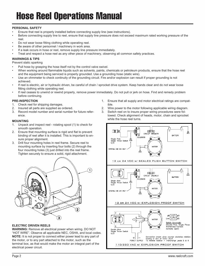
MOUNTING1. Unpack and inspect reel - rotating spool (1) to check for
smooth operation.2. Ensure that mounting surface is rigid and flat to prevent
binding of reel after it is installed. This is important to en-sure proper alignment.
3. Drill four mounting holes in reel frame. Secure reel to mounting surface by inserting four bolts (2) through the four mounting holes (3) just drilled into the reel frame. Tighten securely to ensure a solid, rigid attachment.
Hose Reel Operations Manual
Page 2 www.reelcraft.com
• Ensure that reel is properly installed before connecting supply line (see instructions).• Before connecting supply line to reel, ensure that supply line pressure does not exceed maximum rated working pressure of the
reel.• Do not wear loose fitting clothing while operating reel.• Be aware of other personnel / machinery in work area.• If a leak occurs in hose or reel, remove supply line pressure immediately.• Treat and respect a hose reel as any other piece of machinery, observing all common safety practices.
PERSONAL SAFETY
• Pull hose by grasping the hose itself not by the control valve swivel.• When working around flammable liquids such as solvents, paints, chemicals or petroleum products, ensure that the hose reel
and the equipment being serviced is properly grounded. Use a grounding hose (static wire).• Use an ohmmeter to check continuity of the grounding circuit. Fire and/or explosion can result if proper grounding is not
achieved.• If reel is electric, air or hydraulic driven, be careful of chain / sprocket drive system. Keep hands clear and do not wear loose
fitting clothing while operating reel.• If reel ceases to unwind or rewind properly, remove power immediately. Do not pull or jerk on hose. Find and remedy problem
before continuing.
WARNINGS & TIPSPrevent static sparking
1. Ensure that all supply and motor electrical ratings are compat-ible.
2. Wire power to the motor following applicable wiring diagram.3. Switch reel on to insure proper wiring procedures were fol-
lowed. Check alignment of heads, motor, chain and sprocket while the hose reel turns.
ELECTRIC DRIVEN REELSWARNING: Remove all electrical power when wiring. DO NOT“HOT WIRE”. Observe all applicable NEC, OSHA, and local codes.NOTE: It is not proper to connect either power lead to any part of the motor, or to any part attached to the motor, such as the terminal box, as that would make the motor an integral part of the electrical power circuit.
Hose Reel Operations Manual
www.reelcraft.com Page 3
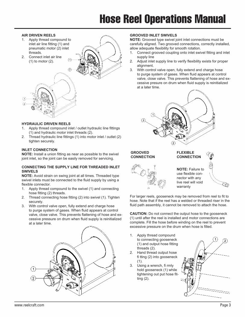
AIR DRIVEN REELS1. Apply thread compound to
inlet air line fitting (1) and pneumatic motor (2) inlet threads.
2. Connect inlet air line (1) to motor (2).
HYDRAULIC DRIVEN REELS1. Apply thread compound inlet / outlet hydraulic line fittings
(1) and hydraulic motor inlet threads (2).2. Thread hydraulic line fittings (1) into motor inlet / outlet (2)
tighten securely.
INLET CONNECTIONNOTE: Install a union fitting as near as possible to the swivel joint inlet, so the joint can be easily removed for servicing.
CONNECTING THE SUPPLY LINE FOR THREADED INLET SWIVELSNOTE: Avoid strain on swing joint at all times. Threaded typeswivel inlets must be connected to the fluid supply by using a flexible connector.1. Apply thread compound to the swivel (1) and connecting
hose fitting (2) threads.2. Thread connecting hose fitting (2) into swivel (1). Tighten
securely.3. With control valve open, fully extend and charge hose
to purge system of gases. When fluid appears at control valve, close valve. This prevents flattening of hose and ex-cessive pressure on drum when fluid supply is reinitialized at a later time.
GROOVED INLET SWIVELSNOTE: Grooved type swivel joint inlet connections must be carefully aligned. Two grooved connections, correctly installed, allow adequate flexibility for smooth rotation.1. Connect grooved coupling onto inlet swivel fitting and inlet
supply line2. Adjust inlet supply line to verify flexibility exists for proper
alignment.3. With control valve open, fully extend and charge hose
to purge system of gases. When fluid appears at control valve, close valve. This prevents flattening of hose and ex-cessive presure on drum when fluid supply is reinitialized at a later time.
GROOVEDCONNECTION
FLEXIBLECONNECTION
NOTE: Failure to use flexible con-nector with any live reel will void warranty
For larger reels, gooseneck may be removed from reel to fit tohose. Note that if the reel has a welded or threaded riser in thefluid path assembly, it cannot be removed to attach the hose.
CAUTION: Do not connect the output hose to the gooseneck(1) until after the reel is installed and motor connections arecomplete. Fill the hose before winding on the reel to preventexcessive pressure on the drum when hose is filled.
1. Apply thread compound to connecting gooseneck (1) and output hose fitting threads (2).
2. Hand thread output hose fi tting (2) into gooseneck (1).
3. Using a wrench, fi rmly hold gooseneck (1) while tightening out put hose fit-ting (2).
Hose Reel Operations Manual
Page 4 www.reelcraft.com
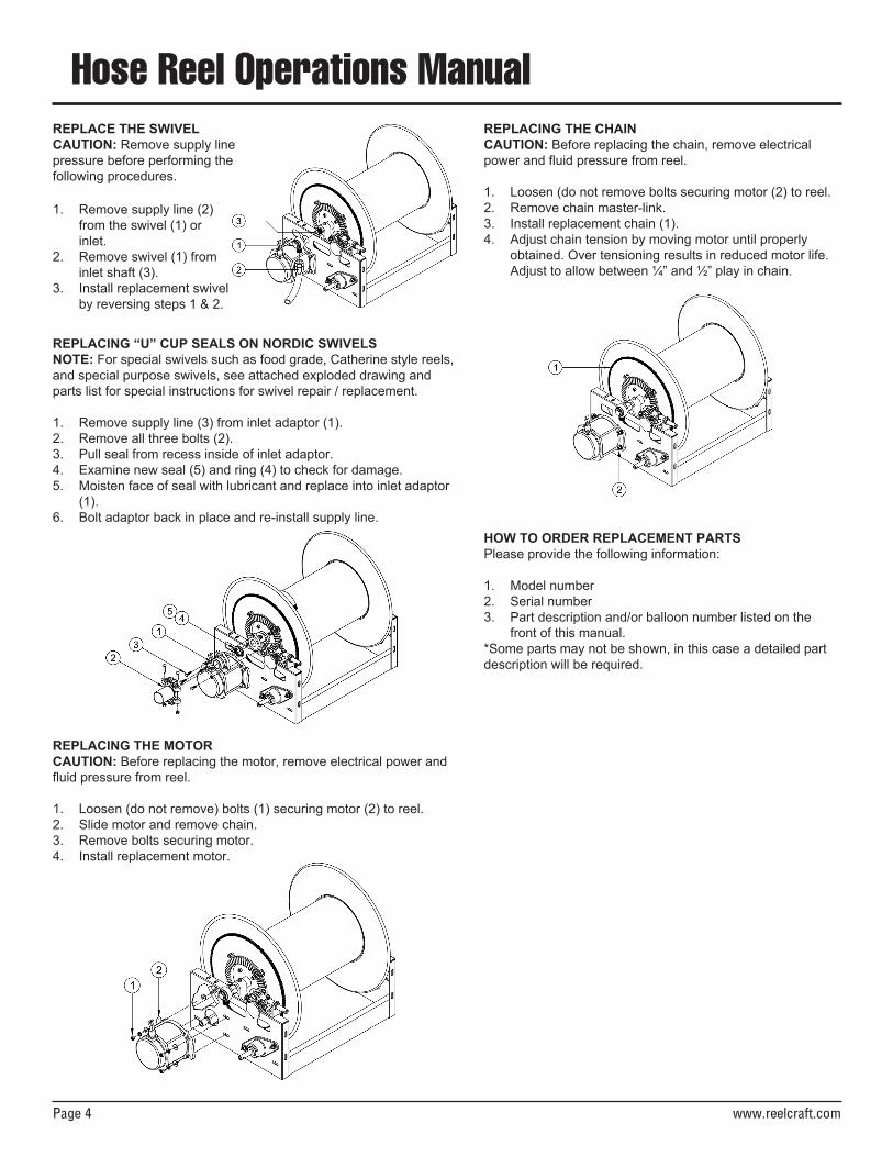
REPLACE THE SWIVELCAUTION: Remove supply line pressure before performing thefollowing procedures.
1. Remove supply line (2) from the swivel (1) or inlet.
2. Remove swivel (1) from inlet shaft (3).
3. Install replacement swivel by reversing steps 1 & 2.
REPLACING “U” CUP SEALS ON NORDIC SWIVELSNOTE: For special swivels such as food grade, Catherine style reels, and special purpose swivels, see attached exploded drawing and parts list for special instructions for swivel repair / replacement.
1. Remove supply line (3) from inlet adaptor (1).2. Remove all three bolts (2).3. Pull seal from recess inside of inlet adaptor.4. Examine new seal (5) and ring (4) to check for damage.5. Moisten face of seal with lubricant and replace into inlet adaptor
(1).6. Bolt adaptor back in place and re-install supply line.
REPLACING THE MOTORCAUTION: Before replacing the motor, remove electrical power and fluid pressure from reel.
1. Loosen (do not remove) bolts (1) securing motor (2) to reel.2. Slide motor and remove chain.3. Remove bolts securing motor.4. Install replacement motor.
REPLACING THE CHAINCAUTION: Before replacing the chain, remove electrical power and fluid pressure from reel.
1. Loosen (do not remove bolts securing motor (2) to reel.2. Remove chain master-link.3. Install replacement chain (1).4. Adjust chain tension by moving motor until properly
obtained. Over tensioning results in reduced motor life. Adjust to allow between ¼” and ½” play in chain.
HOW TO ORDER REPLACEMENT PARTSPlease provide the following information:
1. Model number2. Serial number3. Part description and/or balloon number listed on the
front of this manual. *Some parts may not be shown, in this case a detailed part description will be required.