Embed Size (px)
Citation preview

Proprietary InformationProprietary Information
easYgen-3200 Training Section 6 - LogicsManager
marked
CERTIFICATE of Design Assessment
by ABS American Bureau of Shipping & Affiliated Companies

Proprietary InformationProprietary Information
Contents Introduction
Screen Description
Input Command Variables
Signs
Operators
Time delay
Logical Outputs
Programming
Exercise
slide 3
5
6
11
13
17
18
24
26

3Proprietary Information
The LogicsManagerTM permits the easYgen-3000 operating logic to be customized for each individual application. The status of discrete inputs, discrete outputs, internal conditions, alarms, and measured values may be combined into logical functions. These logical functions may be used to initiate numerous operational functions, such as starting the generator in the automatic mode.
Woodward’s LogicsManagerTM has been developed to give the user complete control for flexible configuration and operation.
IntroductionIntroduction
Description
Input Commands
Signs
Operators
Time Delay
Programming
Logical Outputs
Introduction
Exercise

4Proprietary Information
Internal ConditionsConditions
- CB status- operating mode- engine status
Alarms- warning alarm- shutdown alarm
Time / Date
Assignment
With timer ON-delay and OFF-delay
16 additional/internal flags or logical operations
Digital SignalsDiscrete inputsRelay statusExternal discrete inputsExternal relaysControl via interface
Relay Outputs- Operate free configurable
outputs
Internal Conditions- Start/stop engine- Change operation mode- Acknowledge of alarms- Inhibit emergency mode
Introduction - LogicsManagerTM
IntroductionIntroduction
Description
Input Commands
Signs
Operators
Time Delay
Programming
Logical Outputs
Exercise

5Proprietary Information
Command
Sign
Operator 01
Operator 02
Components of the Boolean Logic equation:
Logical Output Delay ON
Delay OFF
Screen DescriptionIntroduction
DescriptionDescription
Input Commands
Signs
Operators
Time Delay
Programming
Logical Outputs
Exercise

6Proprietary Information
Input Command Variables
The following groups are available:
00 Flags condition (results of LogicsManager outputs)
01 Alarm system (active alarm classes)
02 System condition03 Engine control04 Applications condition05 Engine related alarms06 Generator related alarms07 Mains related alarms08 System related alarms09 Discrete inputs
10 Analog inputs(wire break)
11 Clock and timer12 External DIs13 Discrete outputs14 External DOs15 Flexible limits18 Transistor outputs
(external excitation 12V/24V)
Introduction
Description
Input CommandsInput Commands
Signs
Operators
Time Delay
Programming
Logical Outputs
Exercise

7Proprietary Information
Input Command Variables
Viewing the state of the inputs in ToolKit:Introduction
Description
Input CommandsInput Commands
Signs
Operators
Time Delay
Programming
Logical Outputs
Exercise

8Proprietary Information
Input Command Variables
Viewing the state of the inputs in the HMI:Introduction
Description
Input CommandsInput Commands
Signs
Operators
Time Delay
Programming
Logical Outputs
Exercise
9Proprietary Information
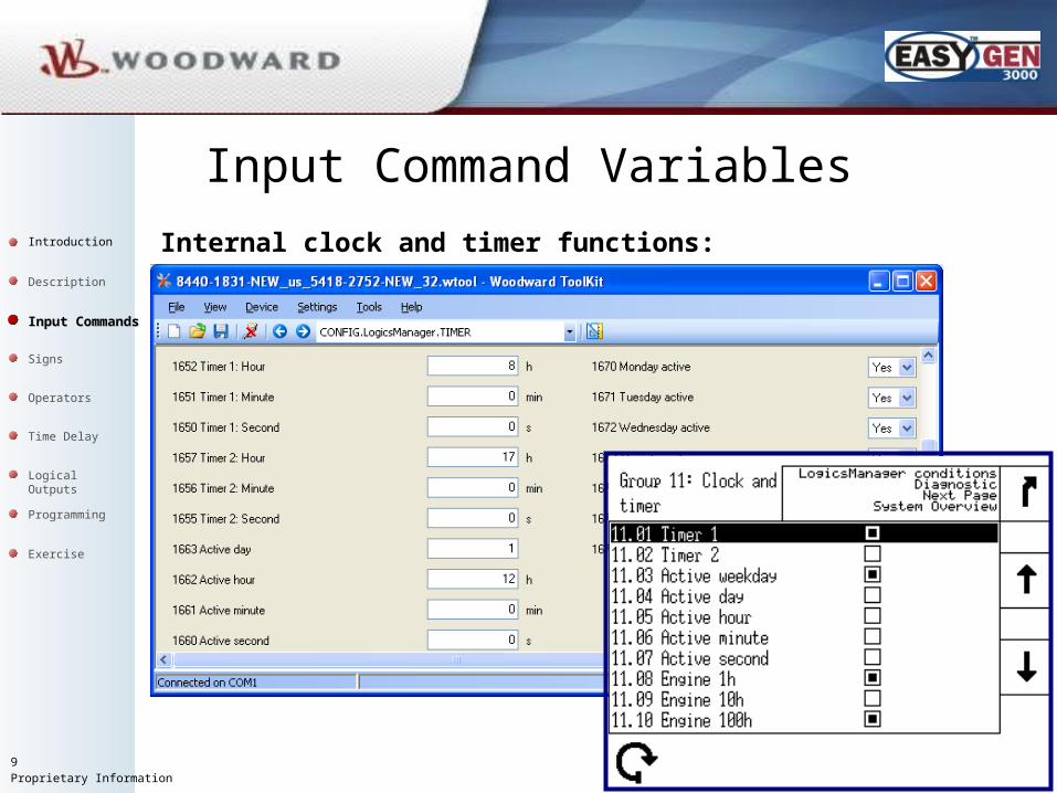
Input Command Variables
Internal clock and timer functions:Introduction
Description
Input CommandsInput Commands
Signs
Operators
Time Delay
Programming
Logical Outputs
Exercise

10Proprietary Information
Input Command VariablesThe alarm class for discrete inputs must be configured as “Control”, if discrete inputs or alarm flags are used as input commands.
Introduction
Description
Input CommandsInput Commands
Signs
Operators
Time Delay
Programming
Logical Outputs
Exercise

11Proprietary Information
• Direct Command value - The command value is
passed directly to the operator
• NOT Command value - The command value is inverted
passed to the operator
• Always "0"- The command value is ignored and
this logic path is always FALSE.
• Always "1"- The command value is ignored and
this logic path is always TRUE.
Signs
The sign defines if the input is enable and how it will be usedIntroduction
Description
Input Commands
SignsSigns
Operators
Time Delay
Programming
Logical Outputs
Exercise

12Proprietary Information
Signs
Command input:
Grey if sign = TRUE or FALSE
Introduction
Description
Input Commands
SignsSigns
Operators
Time Delay
Programming
Logical Outputs
Exercise

13Proprietary Information
Operator 01 and 02
OperatorsIntroduction
Description
Input Commands
Signs
OperatorsOperators
Time Delay
Programming
Logical Outputs
Exercise

14Proprietary Information
x1 x2 y
0 0 0
0 1 0
1 0 0
1 1 1
x1 x2 y
0 0 0
0 1 1
1 0 1
1 1 1
x1 x2 y
0 0 1
0 1 1
1 0 1
1 1 0
Truth tables
x1
x1
x1
x2
x2
x2
AND NANDOR
OperatorsIntroduction
Description
Input Commands
Signs
OperatorsOperators
Time Delay
Programming
Logical Outputs
Exercise

15Proprietary Information
x1 x2 y
0 0 1
0 1 0
1 0 0
1 1 0
x1 x2 y
0 0 1
0 1 0
1 0 0
1 1 1
x1 x2 y
0 0 0
0 1 1
1 0 1
1 1 0
ONON
ON ON
OFF
OFFOFF
OFFx2
x2x2
x1
x1
Truth tables
NOR XORNXOR
OperatorsIntroduction
Description
Input Commands
Signs
OperatorsOperators
Time Delay
Programming
Logical Outputs
Exercise

16Proprietary Information
The “Help” screen gives a description of the logical outputs.
Operators
Press soft key
Introduction
Description
Input Commands
Signs
OperatorsOperators
Time Delay
Programming
Logical Outputs
Exercise

17Proprietary Information
Delay ON
is the amount of time that the logical output state is delayed before changing to true
Delay OFF
is the amount of time that the logical output state is delayed before changing to false
Delay ON Delay OFF
Time DelayIntroduction
Description
Input Commands
Signs
Operators
Time DelayTime Delay
Programming
Logical Outputs
Exercise

18Proprietary Information
Logical Outputs
Logical Functions
Internal Flags
Relay outputs Any discrete output that are freely configurable
Internal functions and conditions such as “Start in Auto” and “Firing Speed reached”
Additional Boolean equations which can be used whenever three input commands are not enough or time delayed signals are required
There are three types available:Introduction
Description
Input Commands
Signs
Operators
Time Delay
Programming
Logical OutputsLogical Outputs
Exercise

19Proprietary Information
Logical Outputs-Relay output 1 Ready for operation OFF-Relay 2 to 12 Depending on configuration-External relays 1-16 via expansion boardcan be used as additional flags if not utilized
Relay outputsIntroduction
Description
Input Commands
Signs
Operators
Time Delay
Programming
Logical OutputsLogical Outputs
Exercise

20Proprietary Information
Logical Outputs
Internal Flags Internal flags 1 to 16
-Flag 1 used as placeholder – use caution when using it for other purposes
-Flag 8 Timer function
Internal flag 8:
Timer1: 08:00.00 Timer2: 17:00.00 Active weekday:
Monday: Yes …..
Friday: YesSaturday: NoSunday: No
Introduction
Description
Input Commands
Signs
Operators
Time Delay
Programming
Logical OutputsLogical Outputs
Exercise

21Proprietary Information
Logical Outputs
Logical Functions
-Start request in AUTO-Stop request in AUTO-Load dependent (LD) start stop-Start w/o load-Critical mode- Inhibit emergency
-External acknowledge
-Undelayed close GCB-External mains decoupling requested
-Enable MCB
-Firing speed reached
Introduction
Description
Input Commands
Signs
Operators
Time Delay
Programming
Logical OutputsLogical Outputs
Exercise

22Proprietary Information
Logical Outputs
Logical Functions
-Setpoint 2 power-Setpoint 2 power factor-Setpoint 2 frequency-Setpoint 2 voltage
-Frequency droop active-Voltage droop active
-Discrete f/P + (raise)-Discrete f/P – (lower)-Discrete V/PF + (raise)-Discrete V/PF – (lower)
-RUN Synchronization mode -CHECK Synchronization mode-PERMISSIVE Synchronization mode
Introduction
Description
Input Commands
Signs
Operators
Time Delay
Programming
Logical OutputsLogical Outputs
Exercise

23Proprietary Information
Logical Outputs
Logical Functions
-Constant idle run-Auto idle mode
-AUTO operation mode-MANUAL operation mode-STOP operation mode
Introduction
Description
Input Commands
Signs
Operators
Time Delay
Programming
Logical OutputsLogical Outputs
Exercise

24Proprietary Information
Change value with + and -
Select component to change with arrows
Select from list in ToolKit
Programming
Go to next input command group
Introduction
Description
Input Commands
Signs
Operators
Time Delay
ProgrammingProgramming
Logical Outputs
Exercise
25Proprietary Information
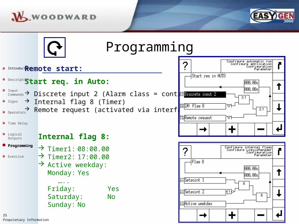
Programming
Remote start:
Start req. in Auto:
Discrete input 2 (Alarm class = control) Internal flag 8 (Timer) Remote request (activated via interface)
Internal flag 8:
Timer1: 08:00.00 Timer2: 17:00.00 Active weekday:
Monday: Yes …..
Friday: YesSaturday: NoSunday: No
Introduction
Description
Input Commands
Signs
Operators
Time Delay
ProgrammingProgramming
Logical Outputs
Exercise

26Proprietary Information
Problem: Create pulsing relay output.
ExerciseIntroduction
Description
Input Commands
Signs
Operators
Time Delay
Programming
Logical Outputs
ExerciseExercise

27Proprietary Information
Create pulsing relays output.
Use as many flags as necessary.
The relay shall only pulse in operating mode MANUAL.
Use relay 11 as pulse relay.
Change the pulse / pause ratio
ExerciseIntroduction
Description
Input Commands
Signs
Operators
Time Delay
Programming
Logical Outputs
ExerciseExercise

28Proprietary Information
Pause time
Exercise
Solution: Create pulsing relay output.
Can be used as a simple process controller if combined with Flexible Limits (alarm class = control). Only digital PID possible with multiple Flexible Limits and different pulse / pause ratios.
Pulse time
Introduction
Description
Input Commands
Signs
Operators
Time Delay
Programming
Logical Outputs
ExerciseExercise

29Proprietary Information
Note:
Information contained herein is intended for and appropriate to the purposes of this publication/presentation. Woodward reserves the right to update or otherwise revise any portion of this publication at any time. Technical data and detailed information is available in Woodward product specs. Specific reliance should be given only to information contained in purchase order(s), other contractual document(s), or information otherwise expressly represented in writing by Woodward as correct and accurate for the specific facts, circumstances and applications.
Other sections are :
1 Overview
2 Hardware and I/O
3 Operational Modes
4 Configuration and ToolKit
5 Communication
6 LogicsManager
7 Analog Manager
8 Controller
9 Synchronization and breaker
10 Application
11 Sequencing
End of this presentationEnd of this presentation
Thank you for your attentionThank you for your attention