Embed Size (px)
Citation preview

Lifts
an
d L
ift Ac
ce
ss
or
ies
Your Source for Water Control GatesNo matter what type of gates your project demands,chances are excellent Hydro Gate has the right gates foryour specific application. Our product offering is vast andcan suit applications for a wide variety of industries.Choose from cast iron slide or flap gates, fabricated slideor flap gates, rectangular butterfly gates, stop logs,wall thimbles, lifts and accessories.
Industries We ServeWhether you need gates for flood control, wastewatertreatment, environmental water treatment, irrigation, damprojects or hydroelectric plants, we can help. From standardconfigurations to custom designs, Hydro Gate offers a widevariety of water control gates as well as a full complement ofactuators to meet your specific application.
Service Well Beyond ShipmentOur services extend beyond manufacturing. Hydro Gate’sexperienced field service technicians can help you withrepair and refurbishment projects. If you have existing,yet serviceable gates, we can perform a retrofit that willextend their life and durability.
Focus on Quality Hydro Gates expansive 90,000 square foot manufacturingfacility utilizes precision equipment that allows us to mergetime-tested gate design with cutting edge technology.We offer large scale manufacturing capabilities with theability to produce cast iron gates up to 14' x 16' in size,and fabricated gates up to and over 20' in width or height.
Pioneers inGate Design
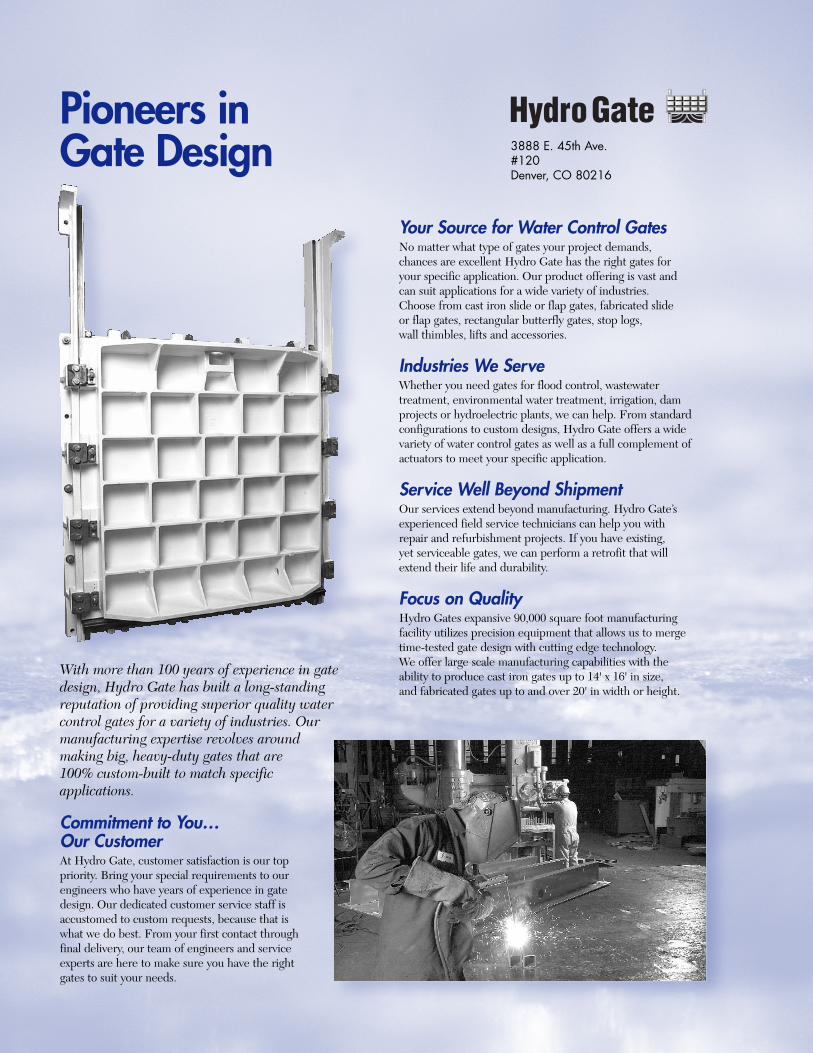
With more than 100 years of experience in gatedesign, Hydro Gate has built a long-standingreputation of providing superior quality watercontrol gates for a variety of industries. Ourmanufacturing expertise revolves aroundmaking big, heavy-duty gates that are100% custom-built to match specificapplications.
Commitment to You…Our CustomerAt Hydro Gate, customer satisfaction is our toppriority. Bring your special requirements to ourengineers who have years of experience in gatedesign. Our dedicated customer service staff isaccustomed to custom requests, because that iswhat we do best. From your first contact throughfinal delivery, our team of engineers and serviceexperts are here to make sure you have the rightgates to suit your needs.
HydroGate3888 E. 45th Ave.#120Denver, CO 80216
1H Y D R O G A T E L I F T S
Hydro GateLifts
HydroGate
Table of Contents
Lifts:
Description ............................................................................................................................2-3
Selection of Lifting Devices ....................................................................................................4
Dimensional Data .................................................................................................................5-6
Geared Lifts:
Description ...............................................................................................................................7
Features.....................................................................................................................................7
Bevel Gear Units...................................................................................................................8-9
Parallel Gear Units .................................................................................................................10
Handwheel Lifts................................................................................................................11-12
Power Operated Lifts .......................................................................................................12-14
Lift Accessories:
Covers ................................................................................................................................14-15
Wall Brackets.....................................................................................................................15-16
Stems..................................................................................................................................16-18
Stem Accessories...............................................................................................................19-21
Packing Gland.........................................................................................................................21
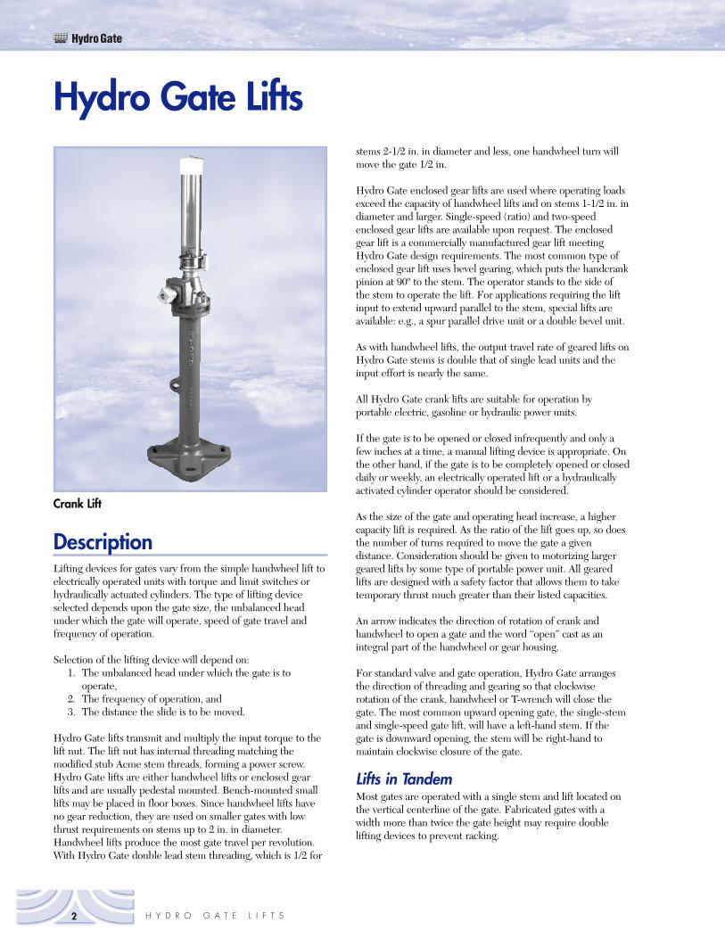
Crank Lift
2 H Y D R O G A T E L I F T S
HydroGate
DescriptionLifting devices for gates vary from the simple handwheel lift toelectrically operated units with torque and limit switches orhydraulically actuated cylinders. The type of lifting deviceselected depends upon the gate size, the unbalanced headunder which the gate will operate, speed of gate travel andfrequency of operation.
Selection of the lifting device will depend on:1. The unbalanced head under which the gate is to
operate,2. The frequency of operation, and3. The distance the slide is to be moved.
Hydro Gate lifts transmit and multiply the input torque to thelift nut. The lift nut has internal threading matching themodified stub Acme stem threads, forming a power screw.Hydro Gate lifts are either handwheel lifts or enclosed gearlifts and are usually pedestal mounted. Bench-mounted smalllifts may be placed in floor boxes. Since handwheel lifts haveno gear reduction, they are used on smaller gates with lowthrust requirements on stems up to 2 in. in diameter.Handwheel lifts produce the most gate travel per revolution.With Hydro Gate double lead stem threading, which is 1/2 for
stems 2-1/2 in. in diameter and less, one handwheel turn willmove the gate 1/2 in.
Hydro Gate enclosed gear lifts are used where operating loadsexceed the capacity of handwheel lifts and on stems 1-1/2 in. indiameter and larger. Single-speed (ratio) and two-speedenclosed gear lifts are available upon request. The enclosedgear lift is a commercially manufactured gear lift meetingHydro Gate design requirements. The most common type ofenclosed gear lift uses bevel gearing, which puts the handcrankpinion at 90º to the stem. The operator stands to the side ofthe stem to operate the lift. For applications requiring the liftinput to extend upward parallel to the stem, special lifts areavailable: e.g., a spur parallel drive unit or a double bevel unit.
As with handwheel lifts, the output travel rate of geared lifts onHydro Gate stems is double that of single lead units and theinput effort is nearly the same.
All Hydro Gate crank lifts are suitable for operation byportable electric, gasoline or hydraulic power units.
If the gate is to be opened or closed infrequently and only afew inches at a time, a manual lifting device is appropriate. Onthe other hand, if the gate is to be completely opened or closeddaily or weekly, an electrically operated lift or a hydraulicallyactivated cylinder operator should be considered.
As the size of the gate and operating head increase, a highercapacity lift is required. As the ratio of the lift goes up, so doesthe number of turns required to move the gate a givendistance. Consideration should be given to motorizing largergeared lifts by some type of portable power unit. All gearedlifts are designed with a safety factor that allows them to taketemporary thrust much greater than their listed capacities.
An arrow indicates the direction of rotation of crank andhandwheel to open a gate and the word “open” cast as anintegral part of the handwheel or gear housing.
For standard valve and gate operation, Hydro Gate arrangesthe direction of threading and gearing so that clockwiserotation of the crank, handwheel or T-wrench will close thegate. The most common upward opening gate, the single-stemand single-speed gate lift, will have a left-hand stem. If thegate is downward opening, the stem will be right-hand tomaintain clockwise closure of the gate.
Lifts in TandemMost gates are operated with a single stem and lift located onthe vertical centerline of the gate. Fabricated gates with awidth more than twice the gate height may require doublelifting devices to prevent racking.
Hydro Gate Lifts
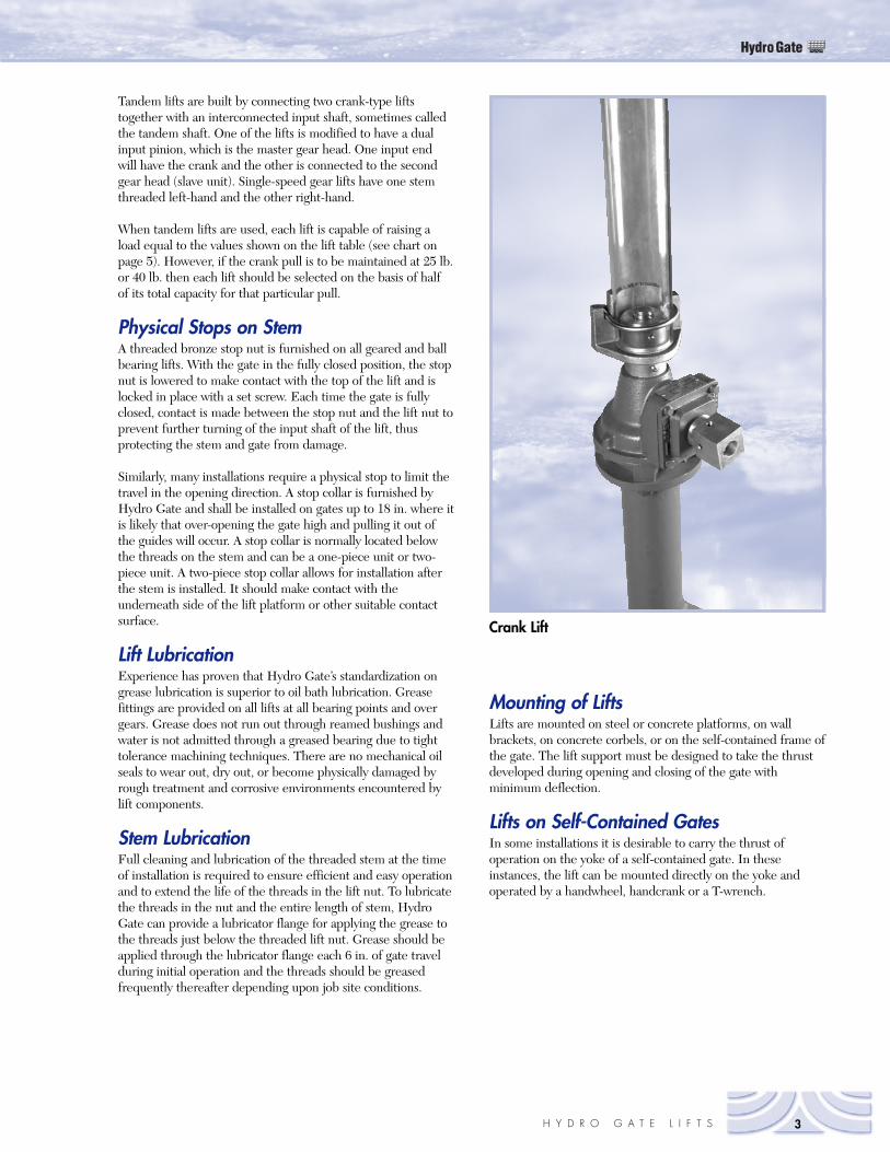
Crank Lift
Tandem lifts are built by connecting two crank-type liftstogether with an interconnected input shaft, sometimes calledthe tandem shaft. One of the lifts is modified to have a dualinput pinion, which is the master gear head. One input endwill have the crank and the other is connected to the secondgear head (slave unit). Single-speed gear lifts have one stemthreaded left-hand and the other right-hand.
When tandem lifts are used, each lift is capable of raising aload equal to the values shown on the lift table (see chart onpage 5). However, if the crank pull is to be maintained at 25 lb.or 40 lb. then each lift should be selected on the basis of halfof its total capacity for that particular pull.
Physical Stops on StemA threaded bronze stop nut is furnished on all geared and ballbearing lifts. With the gate in the fully closed position, the stopnut is lowered to make contact with the top of the lift and islocked in place with a set screw. Each time the gate is fullyclosed, contact is made between the stop nut and the lift nut toprevent further turning of the input shaft of the lift, thusprotecting the stem and gate from damage.
Similarly, many installations require a physical stop to limit thetravel in the opening direction. A stop collar is furnished byHydro Gate and shall be installed on gates up to 18 in. where itis likely that over-opening the gate high and pulling it out ofthe guides will occur. A stop collar is normally located belowthe threads on the stem and can be a one-piece unit or two-piece unit. A two-piece stop collar allows for installation afterthe stem is installed. It should make contact with theunderneath side of the lift platform or other suitable contactsurface.
Lift LubricationExperience has proven that Hydro Gate’s standardization ongrease lubrication is superior to oil bath lubrication. Greasefittings are provided on all lifts at all bearing points and overgears. Grease does not run out through reamed bushings andwater is not admitted through a greased bearing due to tighttolerance machining techniques. There are no mechanical oilseals to wear out, dry out, or become physically damaged byrough treatment and corrosive environments encountered bylift components.
Stem LubricationFull cleaning and lubrication of the threaded stem at the timeof installation is required to ensure efficient and easy operationand to extend the life of the threads in the lift nut. To lubricatethe threads in the nut and the entire length of stem, HydroGate can provide a lubricator flange for applying the grease tothe threads just below the threaded lift nut. Grease should beapplied through the lubricator flange each 6 in. of gate travelduring initial operation and the threads should be greasedfrequently thereafter depending upon job site conditions.
Mounting of LiftsLifts are mounted on steel or concrete platforms, on wallbrackets, on concrete corbels, or on the self-contained frame ofthe gate. The lift support must be designed to take the thrustdeveloped during opening and closing of the gate withminimum deflection.
Lifts on Self-Contained GatesIn some installations it is desirable to carry the thrust ofoperation on the yoke of a self-contained gate. In theseinstances, the lift can be mounted directly on the yoke andoperated by a handwheel, handcrank or a T-wrench.
HydroGate
3H Y D R O G A T E L I F T S
Selection of Lifting DevicesIn order to operate any gate, the lifting device must overcomeseveral forces. These include the weight of the gate slide,weight of the stem, frictional resistance caused by waterpressure against the slide, the frictional resistance caused bythe wedges and hydraulic downpull.
Required Lifting ForceTo determine the lifting force required to open a gate, thefollowing formula is used:
F = 62.4APf+W+w+dp
Where:F = lifting force required in poundsA = area of gate opening in square feetP = effective head of water in feetf = coefficient of frictionW = weight of gate slide in poundsw = weight of stem in poundsdp = downpull in pounds
After the gate has been unwedged, the coefficient of friction isa conservative value of approximately 0.35. As indicated,frictional factors are approximate and will vary depending uponhow long the gate has been in the closed position; if the slide ispartially covered by silt or sand; if the faces are lubricated ordry; and the condition of the threaded portion of the stem.
The area of the square or rectangular gate opening is used todetermine the frictional load created by the water pressure oneither the face or the backside of the gate. The area of thesquare is also used to determine frictional load for round sluicegates since they are made with square slides with the seatingfaces mounted on a square around the circular opening.Therefore, the water pressure is always active against thesquare area.
For roller gate operation, the same formula is used todetermine the lifting force required, except the frictional factoris 0.2. This smaller factor is adequate because this type of gaterolls on rails and has no wedging device. Fabricated slide gateshave a frictional factor range of 0.15 to 0.35 depending on typeof seal and guide liner used.
The force to unwedge, unseat or crack open a gate is aninstantaneous force. Experience indicates that thisinstantaneous friction factor is normally no more than doublethe running friction or 0.70.
Hydraulic downpull is a factor based on head, flow conditions,geometry of the gate slide, structure entrance, exit shapes andgate position. Consult Hydro Gate’s Engineering Departmentfor further details.
Design of Lift PlatformTo start or lift a sluice or slide gate from the fully closedposition, the platform or other mounting for the lift supportdevice must be designed to take the thrust with the minimumamount of deflection.
Selection of Proper LiftsCapacities for lifting devices are shown for 50 ft. lb. Inputtorque (40 lb. Pull) on the crank or handwheel (see table onpages 8, 10 and 11. Lifting devices selected on the basis of a25-lb pull will be easier to operate, but the larger the lift, themore turns of the crank per inch of gate travel will berequired. Regardless of whether the lifting device is selectedon the basis of a 25- or 40-lb pull, the coefficient of friction0.35 is used for lift selection. The crank or handwheel pull isapproximately double that to “crack” the slide from its wedges.The higher pull is only required for a few turns of the crank. Itthen drops back to the 25-or 40-lb average.
There are two basic steps in selecting the lift and stem. Thefirst step is to determine the total lift load and the minimumpermissible stem diameter that can be used with any givengate size. The tables on pages 5 and 6 give theoreticalcombined weight plus downpull values for a wide range of gatesizes operating under unbalanced heads of 5 to 60 ft. After thegate size has been selected and the maximum unbalancedoperating head has been calculated, use these tables todetermine the lift load.
The next step is to determine the actual stem diameterrequired for the stem material selected. The “Allowable Loads”tables (page 18) show the maximum permissible loads for eachsize of stem for various unsupported stem lengths. In selectingthe actual stem size, use a diameter that has a strength at leastequal to the lift load obtained from the table, and a diameterequal to or greater than the minimum needed for columnaction in closing the gate.
HydroGate
4 H Y D R O G A T E L I F T S
HydroGate
5H Y D R O G A T E L I F T S
6 x 6 — — — — — — 98.8 130.8 170.18 x 8 — — — — — — 128.2 171.0 223.2
10 x 10 68.2 80.4 101.1 130.1 167.5 213.4 330.2 480.6 664.7
12 x 12 98.3 12.9 137.5 172.3 217.1 272.0 412.1 592.4 813.114 x 14 138.2 155.1 183.8 224.3 276.5 340.5 503.6 713.8 971.115 x 15 157.0 175.1 205.8 249.1 305.0 373.5 548.2 773.3 1048.8
16 x 16 206.7 225.9 258.6 304.7 364.3 437.3 623.6 949.1 1280.718 x 18 210.0 234.3 275.7 334.1 409.6 502.2 738.5 1043.1 1415.920 x 20 210.1 240.0 291.1 363.3 456.6 571.0 863.2 1239.9 1701.2
21 x 21 231.2 262.5 316.0 391.7 489.6 609.7 916.3 1311.7 1795.824 x 24 307.3 341.9 401.2 485.2 593.8 727.2 1068.1 1507.7 2046.230 x 30 499.4 549.6 636.5 759.9 919.8 1116.4 1619.1 2268.1 3464.3
36 x 36 667.7 682.2 707.4 1104.1 1362.8 1681.0 2495.8 3548.5 4839.139 x 39 883.2 969.4 1120.0 1335.0 1614.5 1958.4 2839.5 3978.3 5374.942 x 42 1074.9 1153.3 1290.8 1487.5 1743.3 2058.3 3596.6 5062.2 6860.0
48 x 48 1482.5 1605.8 1824.1 2137.3 2545.3 3048.3 4338.9 6009.2 8059.054 x 54 2183.4 2356.8 2666.2 3111.7 3693.1 4410.6 6253.6 8640.6 11571.760 x 60 2844.7 3037.7 3385.0 3886.7 4542.8 5353.3 7437.4 10138.9 13458.0
63 x 63 4509.1 4637.9 4870.8 5207.7 5648.8 6193.9 7596.4 9415.2 11650.466 x 66 4105.0 4334.9 4752.5 5357.8 6150.8 7131.4 9655.8 12931.0 16956.972 x 72 4297.1 4552.2 5019.8 5699.9 6592.6 7697.9 10561.1 14244.1 19860.0
78 x 78 4819.7 5110.1 5647.7 6432.4 7464.3 8743.4 12043.0 16331.3 21608.284 x 84 6442.3 6779.8 7410.7 8335.2 9553.1 11064.5 14967.7 20044.8 26295.990 x 90 7895.5 8304.1 9075.9 10210.9 11709.0 13570.4 18382.6 24647.6 32365.3
96 x 96 12291.9 12689.4 13448.4 14568.7 16050.5 17893.6 22664.1 28880.2 36541.8108 x 108 16037.9 16455.6 17271.1 18484.3 20095.4 22104.3 27315.5 34117.9 42511.5120 x 120 20711.9 21153.9 22037.9 23363.9 25131.9 27431.9 33087.9 40601.9 49883.9144 x 144 35084.9 35453.5 36231.5 37419.1 39016.1 41022.7 46264.3 53143.9 61661.5
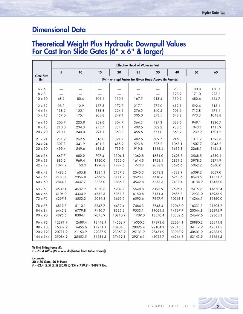
Theoretical Weight Plus Hydraulic Downpull ValuesFor Cast Iron Slide Gates (6" x 6" & larger)
Dimensional Data
Effective Head of Water in Feet
5 10 15 20 25 30 40 50 60Gate Size
(In.) (W + w + dp) Factor for Given Head Above (In Pounds)
To find lifting force (F):F = 62.4 APf + (W + w + dp [factor from table above])
Example:30 x 30 Gate, 20 Ft HeadF = 62.4 (2.5) (2.5) (20.0) (0.35) + 759.9 = 3489.9 lbs.
HydroGate
6 H Y D R O G A T E L I F T S
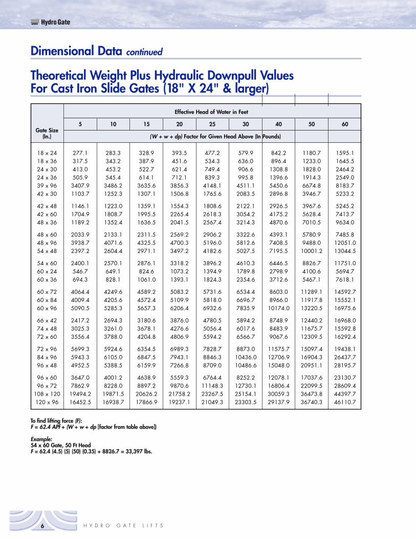
Theoretical Weight Plus Hydraulic Downpull ValuesFor Cast Iron Slide Gates (18" X 24" & larger)
Dimensional Data continued
18 x 24 277.1 283.3 328.9 393.5 477.2 579.9 842.2 1180.7 1595.118 x 36 317.5 343.2 387.9 451.6 534.3 636.0 896.4 1233.0 1645.524 x 30 413.0 453.2 522.7 621.4 749.4 906.6 1308.8 1828.0 2464.224 x 36 505.9 545.4 614.1 712.1 839.3 995.8 1396.6 1914.3 2549.039 x 96 3407.9 3486.2 3635.6 3856.3 4148.1 4511.1 5450.6 6674.8 8183.742 x 30 1103.7 1252.3 1307.1 1506.8 1765.6 2083.5 2896.8 3946.7 5233.2
42 x 48 1146.1 1223.0 1359.1 1554.3 1808.6 2122.1 2926.5 3967.6 5245.242 x 60 1704.9 1808.7 1995.5 2265.4 2618.3 3054.2 4175.2 5628.4 7413.748 x 36 1189.2 1352.4 1636.5 2041.5 2567.4 3214.3 4870.6 7010.5 9634.0
48 x 60 2033.9 2133.1 2311.5 2569.2 2906.2 3322.6 4393.1 5780.9 7485.848 x 96 3938.7 4071.6 4325.5 4700.3 5196.0 5812.6 7408.5 9488.0 12051.054 x 48 2397.2 2604.4 2971.1 3497.2 4182.6 5027.5 7195.5 10001.2 13044.5
54 x 60 2400.1 2570.1 2876.1 3318.2 3896.2 4610.3 6446.5 8826.7 11751.060 x 24 546.7 649.1 824.6 1073.2 1394.9 1789.8 2798.9 4100.6 5694.760 x 36 694.3 828.1 1061.0 1393.1 1824.3 2354.6 3712.6 5467.1 7618.1
60 x 72 4064.4 4249.6 4589.2 5083.2 5731.6 6534.4 8603.0 11289.1 14592.760 x 84 4009.4 4205.6 4572.4 5109.9 5818.0 6696.7 8966.0 11917.8 15552.160 x 96 5090.5 5285.3 5657.3 6206.4 6932.6 7835.9 10174.0 13220.5 16975.6
66 x 42 2417.2 2694.3 3180.6 3876.0 4780.5 5894.2 8748.9 12440.2 16968.074 x 48 3025.3 3261.0 3678.1 4276.6 5056.4 6017.6 8483.9 11675.7 15592.872 x 60 3556.4 3788.0 4204.8 4806.9 5594.2 6566.7 9067.6 12309.5 16292.4
72 x 96 5699.3 5924.6 6354.5 6989.3 7828.7 8873.0 11575.7 15097.4 19438.184 x 96 5943.3 6105.0 6847.5 7943.1 8846.3 10436.0 12706.9 16904.3 26437.796 x 48 4952.5 5388.5 6159.9 7266.8 8709.0 10486.6 15048.0 20951.1 28195.7
96 x 60 3647.0 4001.2 4638.9 5559.3 6764.4 8252.2 12078.1 17037.6 23130.796 x 72 7862.9 8228.0 8897.2 9870.6 11148.3 12730.1 16806.4 22099.5 28609.4
108 x 120 19494.2 19871.5 20626.2 21758.2 23267.5 25154.1 30059.3 36473.8 44397.7120 x 96 16452.5 16938.7 17866.9 19237.1 21049.3 23303.5 29137.9 36740.3 46110.7
Effective Head of Water in Feet
5 10 15 20 25 30 40 50 60Gate Size
(In.) (W + w + dp) Factor for Given Head Above (In Pounds)
To find lifting force (F):F = 62.4 APf + (W + w + dp [factor from table above])
Example:54 x 60 Gate, 50 Ft HeadF = 62.4 (4.5) (5) (50) (0.35) + 8826.7 = 33,397 lbs.
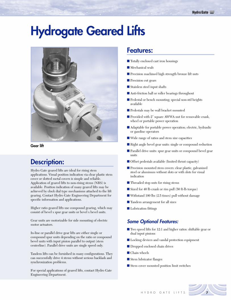
Gear lift
HydroGate
7H Y D R O G A T E L I F T S
Description:Hydro Gate geared lifts are ideal for rising stemapplications. Visual position indication via clear plastic stemcover or slotted metal covers is simple and reliable.Application of geared lifts to non-rising stems (NRS) isavailable. Position indication of many geared lifts may beachieved by clock dial type mechanisms attached to the liftgearing. Contact Hydro Gate Engineering Department forspecific information and applications.
Higher ratio geared lifts use compound gearing, which mayconsist of bevel x spur gear units or bevel x bevel units.
Gear units are motorizable for side mounting of electricmotor actuators.
In-line or parallel drive gear lifts are either single orcompound spur units depending on the ratio or compoundbevel units with input pinion parallel to output (stemcenterline). Parallel drive units are single speed only.
Tandem lifts can be furnished in many configurations. Theycan successfully drive 4 stems without serious backlash andsynchronization problems.
For special applications of geared lifts, contact Hydro GateEngineering Department.
Features:� Totally enclosed cast iron housings
� Mechanical seals
� Precision machined high strength bronze lift nuts
� Precision cut gears
� Stainless steel input shafts
� Anti-friction ball or roller bearings throughout
� Pedestal or bench mounting; special non-std heightsavailable
� Pedestals may be wall bracket mounted
� Provided with 2” square AWWA nut for removable crank,wheel or portable power operation
� Adaptable for portable power operation; electric, hydraulicor gasoline operators
� Wide range of ratios and stem size capacities
� Right angle bevel gear units: single or compound reduction
� Parallel drive units: spur gear units or compound bevel gearunits
� Offset pedestals available (limited thrust capacity)
� Precision mounted stem covers: clear plastic, galvanizedsteel or aluminum without slots or with slots for visualindication
� Threaded stop nuts for rising stems
� Sized for 40 lb crank or rim pull (50 ft-lb torque)
� Withstand 100 lbs (2.5 times) pull without damage
� Tandem arrangement for all sizes
� Lubrication fittings
Some Optional Features:� Two speed lifts for 12:1 and higher ratios: shiftable gear or
dual input pinions
� Locking devices and vandal protection equipment
� Dropped enclosed chain drives
� Chain wheels
� Stem lubricator flanges
� Stem cover mounted position limit switches
Hydrogate Geared Lifts
HydroGate
8 H Y D R O G A T E L I F T S
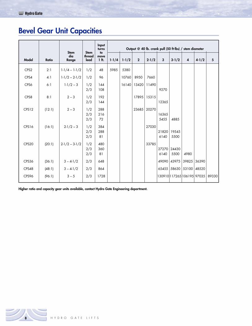
Higher ratio and capacity gear units available, contact Hydro Gate Engineering department.
Bevel Gear Unit Capacities
Inputturns Output @ 40 lb. crank pull (50 ft-lbs) / stem diameter
Stem Stem todia thread move
Model Ratio Range lead 1 ft. 1-1/4 1-1/2 2 2-1/2 3 3-1/2 4 4-1/2 5
CPS2 2:1 1-1/4 – 1-1/2 1/2 48 5985 5380
CPS4 4:1 1-1/2 – 2-1/2 1/2 96 10760 8950 7660
CPS6 6:1 1-1/2 – 3 1/2 144 16140 13420 114902/3 108 9270
CPS8 8:1 2 – 3 1/2 192 17895 153152/3 144 12365
CPS12 (12:1) 2 – 3 1/2 288 23685 202702/3 216 163652/3 72 5455 4885
CPS16 (16:1) 2-1/2 – 3 1/2 384 270302/3 288 21820 195452/3 81 6140 5500
CPS20 (20:1) 2-1/2 – 3-1/2 1/2 480 337852/3 360 27270 244302/3 81 6140 5500 4980
CPS36 (36:1) 3 – 4-1/2 2/3 648 49090 43975 39825 36390
CPS48 (48:1) 3 – 4-1/2 2/3 864 65455 58630 53100 48520
CPS96 (96:1) 3 – 5 2/3 1728 130910117265 106195 97035 89330
HydroGate
9H Y D R O G A T E L I F T S
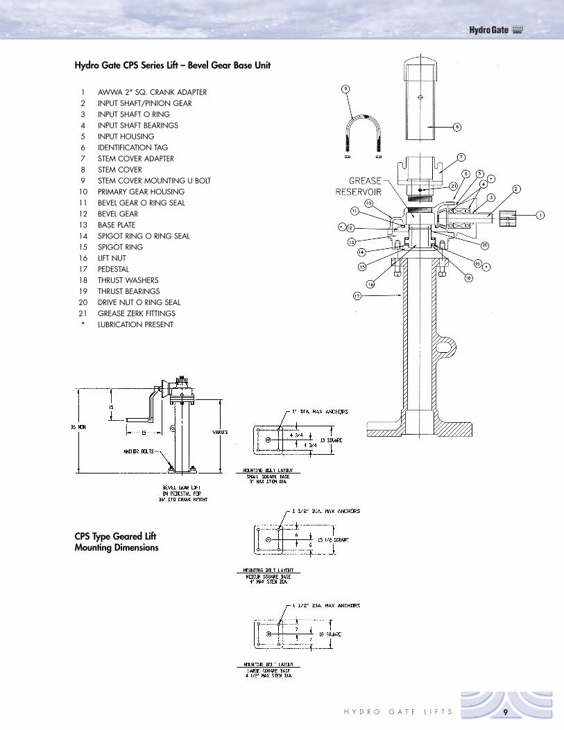
Hydro Gate CPS Series Lift – Bevel Gear Base Unit
1 AWWA 2" SQ. CRANK ADAPTER2 INPUT SHAFT/PINION GEAR3 INPUT SHAFT O RING4 INPUT SHAFT BEARINGS5 INPUT HOUSING6 IDENTIFICATION TAG7 STEM COVER ADAPTER8 STEM COVER9 STEM COVER MOUNTING U BOLT10 PRIMARY GEAR HOUSING11 BEVEL GEAR O RING SEAL12 BEVEL GEAR13 BASE PLATE14 SPIGOT RING O RING SEAL15 SPIGOT RING16 LIFT NUT17 PEDESTAL18 THRUST WASHERS19 THRUST BEARINGS20 DRIVE NUT O RING SEAL21 GREASE ZERK FITTINGS* LUBRICATION PRESENT
CPS Type Geared LiftMounting Dimensions
HydroGate
10 H Y D R O G A T E L I F T S
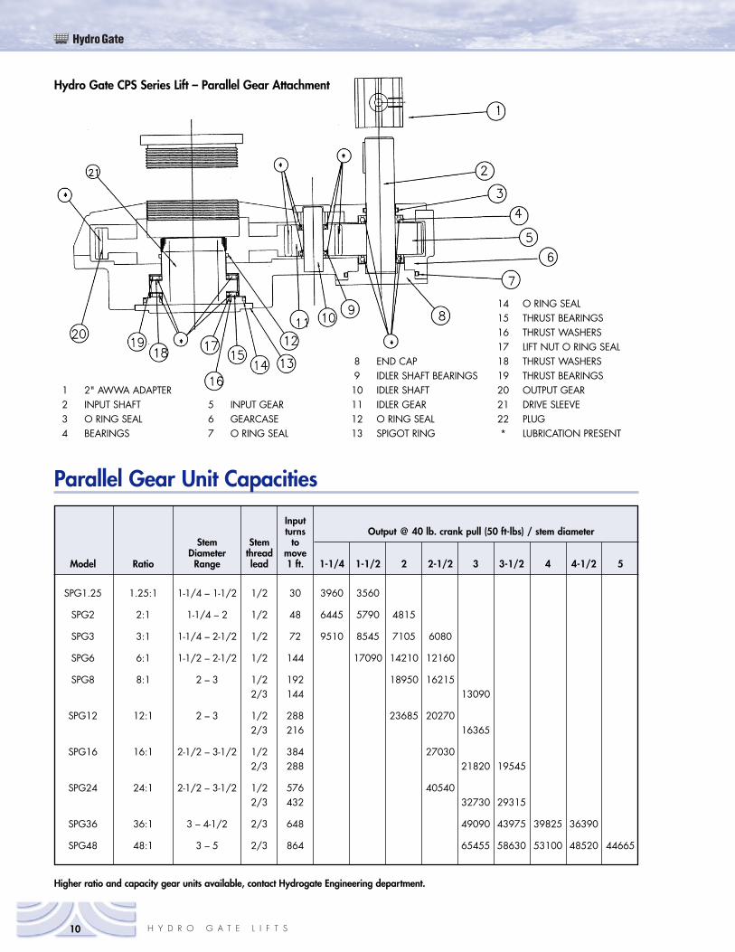
Hydro Gate CPS Series Lift – Parallel Gear Attachment
1 2" AWWA ADAPTER2 INPUT SHAFT3 O RING SEAL4 BEARINGS
5 INPUT GEAR6 GEARCASE7 O RING SEAL
8 END CAP9 IDLER SHAFT BEARINGS10 IDLER SHAFT11 IDLER GEAR12 O RING SEAL13 SPIGOT RING
14 O RING SEAL15 THRUST BEARINGS16 THRUST WASHERS17 LIFT NUT O RING SEAL18 THRUST WASHERS19 THRUST BEARINGS20 OUTPUT GEAR21 DRIVE SLEEVE22 PLUG* LUBRICATION PRESENT
Higher ratio and capacity gear units available, contact Hydrogate Engineering department.
Parallel Gear Unit Capacities
Inputturns Output @ 40 lb. crank pull (50 ft-lbs) / stem diameter
Stem Stem toDiameter thread move
Model Ratio Range lead 1 ft. 1-1/4 1-1/2 2 2-1/2 3 3-1/2 4 4-1/2 5
SPG1.25 1.25:1 1-1/4 – 1-1/2 1/2 30 3960 3560
SPG2 2:1 1-1/4 – 2 1/2 48 6445 5790 4815
SPG3 3:1 1-1/4 – 2-1/2 1/2 72 9510 8545 7105 6080
SPG6 6:1 1-1/2 – 2-1/2 1/2 144 17090 14210 12160
SPG8 8:1 2 – 3 1/2 192 18950 162152/3 144 13090
SPG12 12:1 2 – 3 1/2 288 23685 202702/3 216 16365
SPG16 16:1 2-1/2 – 3-1/2 1/2 384 270302/3 288 21820 19545
SPG24 24:1 2-1/2 – 3-1/2 1/2 576 405402/3 432 32730 29315
SPG36 36:1 3 – 4-1/2 2/3 648 49090 43975 39825 36390
SPG48 48:1 3 – 5 2/3 864 65455 58630 53100 48520 44665
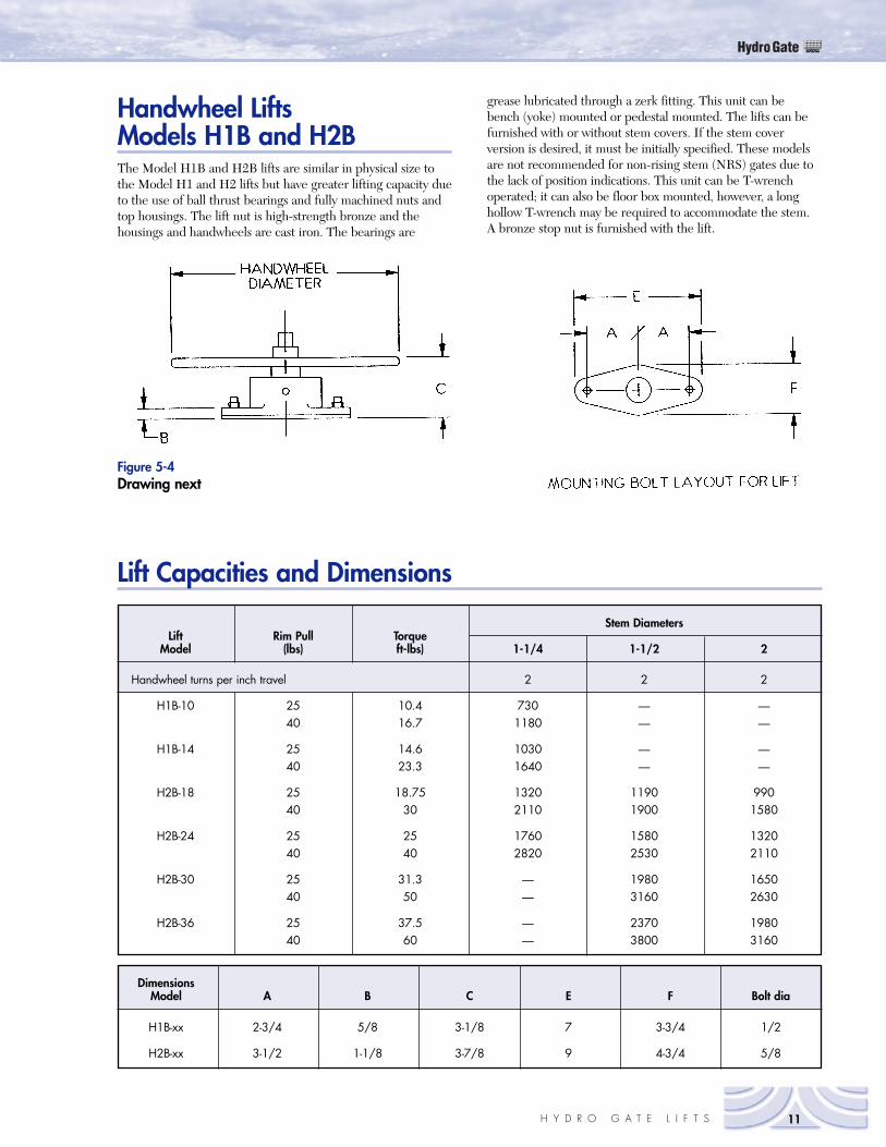
Handwheel turns per inch travel 2 2 2
H1B-10 25 10.4 730 — —40 16.7 1180 — —
H1B-14 25 14.6 1030 — —40 23.3 1640 — —
H2B-18 25 18.75 1320 1190 99040 30 2110 1900 1580
H2B-24 25 25 1760 1580 132040 40 2820 2530 2110
H2B-30 25 31.3 — 1980 165040 50 — 3160 2630
H2B-36 25 37.5 — 2370 198040 60 — 3800 3160
Handwheel LiftsModels H1B and H2BThe Model H1B and H2B lifts are similar in physical size tothe Model H1 and H2 lifts but have greater lifting capacity dueto the use of ball thrust bearings and fully machined nuts andtop housings. The lift nut is high-strength bronze and thehousings and handwheels are cast iron. The bearings are
grease lubricated through a zerk fitting. This unit can bebench (yoke) mounted or pedestal mounted. The lifts can befurnished with or without stem covers. If the stem coverversion is desired, it must be initially specified. These modelsare not recommended for non-rising stem (NRS) gates due tothe lack of position indications. This unit can be T-wrenchoperated; it can also be floor box mounted, however, a longhollow T-wrench may be required to accommodate the stem. A bronze stop nut is furnished with the lift.
HydroGate
11H Y D R O G A T E L I F T S
Figure 5-4 Drawing next
Lift Capacities and Dimensions
Stem DiametersLift Rim Pull Torque
Model (lbs) ft-lbs) 1-1/4 1-1/2 2
H1B-xx 2-3/4 5/8 3-1/8 7 3-3/4 1/2
H2B-xx 3-1/2 1-1/8 3-7/8 9 4-3/4 5/8
DimensionsModel A B C E F Bolt dia
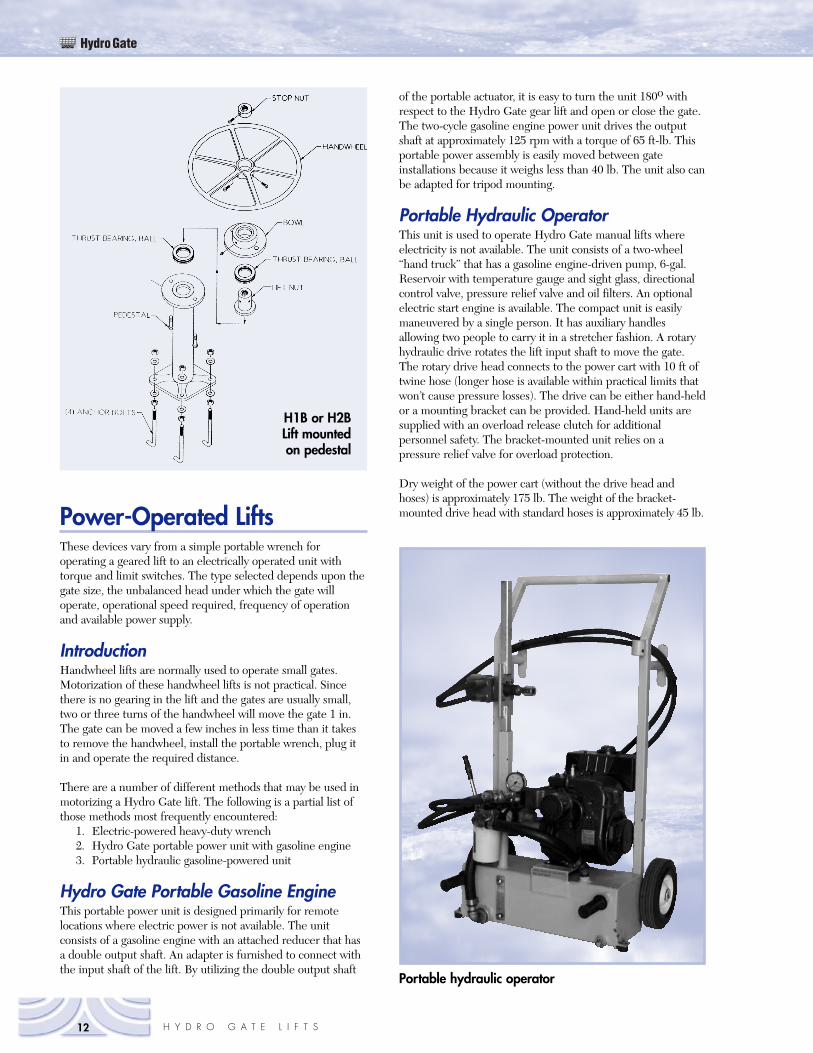
Portable hydraulic operator
of the portable actuator, it is easy to turn the unit 180o withrespect to the Hydro Gate gear lift and open or close the gate.The two-cycle gasoline engine power unit drives the outputshaft at approximately 125 rpm with a torque of 65 ft-lb. Thisportable power assembly is easily moved between gateinstallations because it weighs less than 40 lb. The unit also canbe adapted for tripod mounting.
Portable Hydraulic OperatorThis unit is used to operate Hydro Gate manual lifts whereelectricity is not available. The unit consists of a two-wheel“hand truck” that has a gasoline engine-driven pump, 6-gal.Reservoir with temperature gauge and sight glass, directionalcontrol valve, pressure relief valve and oil filters. An optionalelectric start engine is available. The compact unit is easilymaneuvered by a single person. It has auxiliary handlesallowing two people to carry it in a stretcher fashion. A rotaryhydraulic drive rotates the lift input shaft to move the gate.The rotary drive head connects to the power cart with 10 ft oftwine hose (longer hose is available within practical limits thatwon’t cause pressure losses). The drive can be either hand-heldor a mounting bracket can be provided. Hand-held units aresupplied with an overload release clutch for additionalpersonnel safety. The bracket-mounted unit relies on apressure relief valve for overload protection.
Dry weight of the power cart (without the drive head andhoses) is approximately 175 lb. The weight of the bracket-mounted drive head with standard hoses is approximately 45 lb.
HydroGate
12 H Y D R O G A T E L I F T S
Power-Operated LiftsThese devices vary from a simple portable wrench foroperating a geared lift to an electrically operated unit withtorque and limit switches. The type selected depends upon thegate size, the unbalanced head under which the gate willoperate, operational speed required, frequency of operationand available power supply.
IntroductionHandwheel lifts are normally used to operate small gates.Motorization of these handwheel lifts is not practical. Sincethere is no gearing in the lift and the gates are usually small,two or three turns of the handwheel will move the gate 1 in.The gate can be moved a few inches in less time than it takesto remove the handwheel, install the portable wrench, plug itin and operate the required distance.
There are a number of different methods that may be used inmotorizing a Hydro Gate lift. The following is a partial list ofthose methods most frequently encountered:
1. Electric-powered heavy-duty wrench2. Hydro Gate portable power unit with gasoline engine3. Portable hydraulic gasoline-powered unit
Hydro Gate Portable Gasoline EngineThis portable power unit is designed primarily for remotelocations where electric power is not available. The unitconsists of a gasoline engine with an attached reducer that hasa double output shaft. An adapter is furnished to connect withthe input shaft of the lift. By utilizing the double output shaft
H1B or H2BLift mountedon pedestal
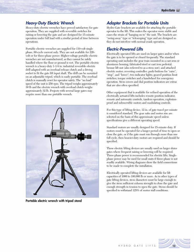
Heavy-Duty Electric WrenchHeavy-duty electric wrenches have proved satisfactory for gateoperation. They are supplied with reversible switches forraising or lowering the gate and are designed for 15-minuteoperation under full load with a similar period of time betweenoperations.
Portable electric wrenches are supplied for 110-volt singlephase, 60-cycle current only. They are not available for 220-volt or for three-phase power. Higher-voltage portable electricwrenches are not manufactured, as they cannot be safelyhandled where the floor or ground is wet. The portable electricwrench is a heavy-duty 1-1/4 in. industrial reversible electricdrill adapted with an overload release clutch and a drivingsocket to fit the gate lift input shaft. The drill can be mountedon an adjustable tripod, which is easily portable. The overloadclutch is manually reset for operator safety. The “no load”speed of the unit is 250 rpm. The tripod weighs approximately30 lb and the electric wrench with overload clutch weighsapproximately 32 lb. Projects with several large gates mayrequire more than one portable wrench.
Adapter Brackets for Portable UnitsHydro Gate brackets are available for attaching the portableoperator to the lift. This makes the operator more stable andeases the strain of “hanging on to” the unit. The brackets are“swing-away” type or “telescoping” type and are designed sothey do not interfere with normal crank operation.
Electric-Powered LiftsElectrically operated lifts are used on larger gates and/or whenthe gate is to be opened or closed frequently. The standardoperating unit includes the gear train mounted in a cast iron oraluminum housing; fabricated-steel or cast iron pedestal;bronze lift nut (also referred to as a stem nut); and attachedelectric motor; reversing controller; push-buttons for “raise”,“stop”, and “lower”; two indicator lights; geared position limitswitches; torque switches and a handwheel for emergencyoperation. Stem covers and dial position indicators are extrasthat are also often specified.
Other equipment that is available for refined operation of theelectrically actuated lifts includes remote position indicator,remote and automatic controls, tandem operation, explosion-proof and submersible motors and modulating controls.
For this type of lifting device, 12 in. of gate travel per minuteis considered standard. The gear ratio and motor size areselected on the basis of this approximate speed unlessspecifications give a different operating speed.
Standard motors are usually designed for 15-minute duty. Ifmotors must be operated for a longer period of time to open orclose the gate, or if the gate must run through more than onefull cycle, then heavier-duty motors are required and should bespecified.
These electric lifting devices are usually used on larger sluicegates where frequent raising or lowering will be required.Three-phase power is recommended for electric lifts. Single-phase power may be used for small units if three-phase is notreadily available. Wiring diagrams show the field connectionsto be made to complete the installation.
Electrically operated lifting devices are available for liftcapacities of 1000 to 100,000 lb or more. As in other types ofgate lifting devices, stem diameters must be large enough togive the stem sufficient column strength to close the gate andenough strength in tension to open the gate. Stems should bespecified to withstand 125% of motor stall conditions.
HydroGate
13H Y D R O G A T E L I F T S
Portable electric wrench with tripod stand
Hydraulic CylindersHydraulic cylinders can also be used to operate sluice gates.Cylinders up to and including 14-in. diameters are readilyavailable at a reasonable cost. Larger diameters can bemanufactured but require extra lead times. Standard cylindersare readily available to operate with oil pressures at 2000 psi.
The principle of hydraulic cylinder operation is simple. Fluid,usually oil, is introduced under pressure into the cylinderthrough ports at the top and bottom. This pressure acts againsta piston that is connected to one end of the cylinder rod andthe gate slide that is attached to the other end. The cylinderrod thus becomes the gate stem. In opening the gate, pressureis introduced through a valve at the bottom side of the piston.This pressure is exerted equally to the interior of the cylinder,including the cylinder wall, the bottom end cap and the piston.The area of the piston in square inches, minus the ineffectivearea taken up by the piston rod, multiplied by the pressure inpounds per square inch, gives the total force available forlifting the gate (Lifting Force = (piston area (in2) - rod area(in2) x system pressure )psi).
Design of Hydraulic SystemsThe design of the hydraulic system, including the necessaryvalving, pump, motor, and tubing are the responsibility of thegate manufacturer. The pump and motor must be of adequatesize to deliver the operating fluid under the required pressureand in a sufficient amount to lift the gate in the time specified.Tubing must be of adequate size to transmit the requiredvolume of oil to operate the gate at the specified speed. If thetubing is longer, there will be a considerable pressure dropunless the tubing is of adequate size. Long hydraulic linesrunning between the pump and the cylinder cause a loss ofpressure. The oil has to be pumped to the cylinder and anequal amount of force is required to return the oil from thecylinder to the pump.
Urethane lip-type “No-Leak” seals should always be specifiedfor piston seals to minimize leakage past the piston. Even withthis type of seal, special precautions must be taken to avoid“drift” of the gate slide if it is to be in the open position for anylength of time. An accumulator may be installed in the systemto compensate for loss of pressure on the underneath side ofthe cylinder or external locking devices may be engineered forspecial applications.
For more information concerning the design of hydraulicsystems, please consult Hydro Gate’s Hydraulic EngineeringDepartment.
Lift AccessoriesStem CoversA Hydro Gate stem cover protects the greased threadedportion of the stem from the weather when the gate isnormally in the open position. Stem covers give the lift afinished appearance. Many lifts used in water and sewagetreatment plants are installed indoors. On such installations,the stem cover is also recommended as it covers the greasystem to improve its appearance and protect the clothing ofvisitors and operating personnel.
Stem covers are commonly made from standard-weightgalvanized steel pipe, aluminum pipe and clear plastic. Eachtype of cover has advantages and disadvantages listed below.
Galvanized Steel Stem CoversGalvanized steel stem covers are used to reduce maintenance.The galvanized interior of the pipe prevents rusting. Thesecovers are somewhat more vandal-proof than other types ofstem covers as they are heavy enough to deflect small debris.The biggest disadvantage of the steel cover is its weight,especially on larger gates. Longer lengths and larger diametersmake it difficult to remove the cover without the aid of a hoist.
Aluminum CoversAluminum covers are lighter weight and are adequate forprotection against corrosion on most installations. They may besubject to vandalism or damage from small flying objects.
Galvanized steel and aluminum covers are furnished with pipethreads on both top and bottom. The top is closed by astandard pipe cap. The bottom end of the cover is screwed intoa threaded housing mounted on the top of the lift orhandwheel, with the exception of the H1B and H2B lifts. Theyare attached to the saddle on the handwheel with a U-boltclamp. Steel and aluminum stem covers for handwheel lifts arescrewed into a threaded adapter cast as an integral part of thehandwheel.
Clear Plastic CoversClear plastic covers are fitted into an adapter that is attached tothe top of the lift housing. A dial indicator is not required withthis type of cover as the rising stem is visible through the cover.This cover is very lightweight and can be easily removed byhand. Plastic stem covers have the following disadvantages:
1. They are subject to breakage from rough handlingduring installation.
2. They are subject to vandalism.
Slotted Metal Stem CoversSteel or aluminum stem covers, with open slots or plastic-covered slots, combine the durability of metallic covers and thestem visibility of clear plastic. Clear plastic windows areattached and sealed for a totally enclosed, slotted stem cover.Reference marks can be painted or stamped on the body of thecover and the stop nut to provide a “pointer” on the stem. Inthe fully closed position, the stop nut may be on view in thebottom end of the slot.
HydroGate
14 H Y D R O G A T E L I F T S
Custom Design IndicatorsVarious methods of utilizing pointers or markers on tail rodsfor indication of the gate position have been utilized withvarying success. Your Hydro Gate Sales Representative canobtain details of custom-engineered indicating devices forspecial applications since project requirements may need tocoordinate these devices with limit switches, float controls orremote indication.
Hydro Gate Offset PedestalsFor those installations where clearance for complete openingof the gate slide is a problem, cast iron pedestals of the offsettype can be used in place of wall brackets. Because the base ofthe offset pedestal is mounted on top of the concrete, the slidecan be raised to a higher elevation.
Offset pedestals are available for H2B, CPS-2 and CPS-4 lifts.Offset pedestals for larger lifts are not recommended becausethe greater capacities make the design and anchoring of theoffset pedestals to the floor undesirable. Pedestal wallssupporting the offset pedestal must be a minimum of 12 in.thick to support the base.
Hydro Gate Floor BoxesThere are three basic arrangements for floor box operation ofgates. Each arrangement has a unique variation:
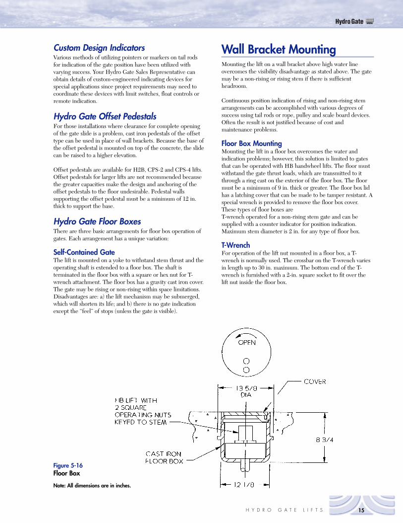
Self-Contained GateThe lift is mounted on a yoke to withstand stem thrust and theoperating shaft is extended to a floor box. The shaft isterminated in the floor box with a square or hex nut for T-wrench attachment. The floor box has a gravity cast iron cover.The gate may be rising or non-rising within space limitations.Disadvantages are: a) the lift mechanism may be submerged,which will shorten its life; and b) there is no gate indicationexcept the “feel” of stops (unless the gate is visible).
Wall Bracket MountingMounting the lift on a wall bracket above high water lineovercomes the visibility disadvantage as stated above. The gatemay be a non-rising or rising stem if there is sufficientheadroom.
Continuous position indication of rising and non-rising stemarrangements can be accomplished with various degrees ofsuccess using tail rods or rope, pulley and scale board devices.Often the result is not justified because of cost andmaintenance problems.
Floor Box MountingMounting the lift in a floor box overcomes the water andindication problems; however, this solution is limited to gatesthat can be operated with HB handwheel lifts. The floor mustwithstand the gate thrust loads, which are transmitted to itthrough a ring cast on the exterior of the floor box. The floormust be a minimum of 9 in. thick or greater. The floor box lidhas a latching cover that can be made to be tamper resistant. Aspecial wrench is provided to remove the floor box cover.These types of floor boxes are T-wrench operated for a non-rising stem gate and can besupplied with a counter indicator for position indication.Maximum stem diameter is 2 in. for any type of floor box.
T-WrenchFor operation of the lift nut mounted in a floor box, a T-wrench is normally used. The crossbar on the T-wrench variesin length up to 30 in. maximum. The bottom end of the T-wrench is furnished with a 2-in. square socket to fit over thelift nut inside the floor box.
HydroGate
15H Y D R O G A T E L I F T S
Figure 5-16Floor Box
Note: All dimensions are in inches.
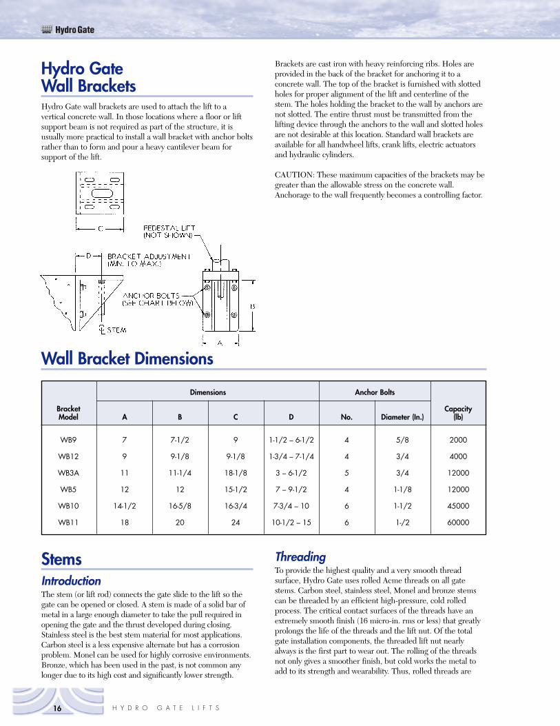
Hydro GateWall BracketsHydro Gate wall brackets are used to attach the lift to avertical concrete wall. In those locations where a floor or liftsupport beam is not required as part of the structure, it isusually more practical to install a wall bracket with anchor boltsrather than to form and pour a heavy cantilever beam forsupport of the lift.
Brackets are cast iron with heavy reinforcing ribs. Holes areprovided in the back of the bracket for anchoring it to aconcrete wall. The top of the bracket is furnished with slottedholes for proper alignment of the lift and centerline of thestem. The holes holding the bracket to the wall by anchors arenot slotted. The entire thrust must be transmitted from thelifting device through the anchors to the wall and slotted holesare not desirable at this location. Standard wall brackets areavailable for all handwheel lifts, crank lifts, electric actuatorsand hydraulic cylinders.
CAUTION: These maximum capacities of the brackets may begreater than the allowable stress on the concrete wall.Anchorage to the wall frequently becomes a controlling factor.
HydroGate
16 H Y D R O G A T E L I F T S
Wall Bracket Dimensions
WB9 7 7-1/2 9 1-1/2 – 6-1/2 4 5/8 2000
WB12 9 9-1/8 9-1/8 1-3/4 – 7-1/4 4 3/4 4000
WB3A 11 11-1/4 18-1/8 3 – 6-1/2 5 3/4 12000
WB5 12 12 15-1/2 7 – 9-1/2 4 1-1/8 12000
WB10 14-1/2 16-5/8 16-3/4 7-3/4 – 10 6 1-1/2 45000
WB11 18 20 24 10-1/2 – 15 6 1-/2 60000
Dimensions Anchor Bolts
Bracket CapacityModel A B C D No. Diameter (In.) (lb)
StemsIntroductionThe stem (or lift rod) connects the gate slide to the lift so thegate can be opened or closed. A stem is made of a solid bar ofmetal in a large enough diameter to take the pull required inopening the gate and the thrust developed during closing.Stainless steel is the best stem material for most applications.Carbon steel is a less expensive alternate but has a corrosionproblem. Monel can be used for highly corrosive environments.Bronze, which has been used in the past, is not common anylonger due to its high cost and significantly lower strength.
ThreadingTo provide the highest quality and a very smooth threadsurface, Hydro Gate uses rolled Acme threads on all gatestems. Carbon steel, stainless steel, Monel and bronze stemscan be threaded by an efficient high-pressure, cold rolledprocess. The critical contact surfaces of the threads have anextremely smooth finish (16 micro-in. rms or less) that greatlyprolongs the life of the threads and the lift nut. Of the totalgate installation components, the threaded lift nut nearlyalways is the first part to wear out. The rolling of the threadsnot only gives a smoother finish, but cold works the metal toadd to its strength and wearability. Thus, rolled threads are
superior in all respects to those that are machine cut. HydroGate uses left-hand, double lead threads to comply with thestandard practice in the valve industry, and to achievestandardization of the direction of rotation to open and closegates and valves. Utilization of the smoother thread and doublelead provides almost twice the efficiency of the mechanism.With approximately the same amount of energy input, the gateslide moves twice as far per turn of the crank or handwheelcompared to single lead cut threads. Standard stem diametersof the unthreaded section of the stems are 1-1/8, 1-3/8, 1-7/8,2-3/8, 2-7/8, 3-3/8, 3-7/8, 4-3/8 and 4-7/8 in. The displacementof metal during thread rolling produces nominal diameters of1-1/4, 1-1/2, 2, 2-1/2, 3, 3-1/2, 4 and 5 in. respectively.
Strength of StemsThe stem acts in tension during opening of the gate and incompression as a column when the gate is being closed. Thecritical factor is nearly always in column action during closing.To reduce the effective length of the column, stem guides areused. A sufficient number of guides should be provided toreduce the unsupported length of column to the maximum l/rof 200 (slenderness ratio).
Lesser values of l/r allow greater column loads to be applied tovarious stem sizes per the table on page 11-9. However, stem guidespacing must be long enough to allow for the full gate opening.
Hydro Gate acquired column test results that were conductedseveral years ago by an independent laboratory. These testsshowed that a stem (rising type) acting as a long column inclosing of the gate, closely approaches the end conditions equalto that of fixed ends. Based on tests, and many years of fieldexperience, stems designed with the slenderness ratio of 200are in accordance with good engineering practice.
When higher gate openings are encountered, the distancerequired for the gate slide to open completely may be the factordetermining the stem size. The location of the first stem guideabove the top of the opening must be high enough to allow theslide to open fully. This same location also determines theminimum stem diameter that can be used with any given gatesize. Ferrous metals have a specific advantage over copper-basedmetals for gate stems (long columns). They are considerablystronger as a column because of the higher modulus of elasticity(Young’s modulus) of steel (both carbon and stainless steel).Euler’s column formula: PCRITICAL=2 2EA/(l/r)2 states that thestress is directly proportional to the modulus of elasticity of thematerial in long, slender columns. The modulus of elasticity ofsteel is 29,500,000 psi; for bronze, it is 15,500,000 psi. Since themodulus of elasticity and not the strength of the material is thegoverning factor in the selection of stems, it is evident that theferrous-metal stem can be of smaller diameter than that of abronze stem for the same loading conditions.
The other factor in the above formula that affects the load-carrying capacity of the stem as a column is the factor K. Itprimarily represents the end fixity of the column; however,straightness of the material also affects the value of K. Throughactual laboratory tests on file with Hydro Gate, K values forstems were determined. The load-carrying capacities arearrived at by determining the maximum load capacity for each
given stem diameter and unsupported length. These values arethen reduced by application of necessary safety factors.
This method for stem design results in an allowable working loadmore than double that needed to close the gate under the givencondition. In rare cases where even these maximum conditionsmay be exceeded, Hydro Gate recommends that the stem shouldact as the “fuse plug” for the gate installation. Damage to gate andlift components or to the supporting structure is thus avoided.
With electric power actuators, the common practice is todetermine the size of a stem and space guides such that thestem can withstand stalled motor (locked rotor) conditions.The idea behind this is that a burned out electric motor ismore easily replaced than a bent stem or broken gate.
Stainless Steel StemsStainless steel stems with approximately 18% chromium and8% nickel have performed well in most corrosive environmentsin which gates are installed. The Series 300 stainless steels arecommonly used for stems. Types 303, 304 and 305 all havenearly equal corrosion resistance. Type 303 is a machininggrade and Type 304 is better for cold working.
Type 316 has a higher corrosion resistance and in those fewinstallations where corrosive conditions justify spending theadditional money, Type 316 stainless steel can be furnished at ahigher cost. Standard Hydro Gate rolled threads can befurnished with this type of stainless steel.
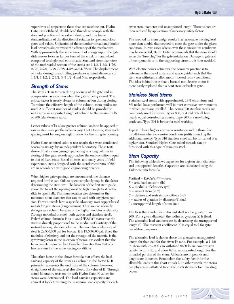
Stem CapacityThe following table shows capacities for a given stem diameterand unsupported lengths. Capacities are calculated using theEuler column formula:
Pcritical = EAC�2 (r/l)2 where:P = axial load on stem (lb)E = modulus of elasticity (psi)A = area of stem (in.2)C = defines end restraint conditions (=2)r = radius of gyration (= diameter/4) (in.)l = unsupported length of stem (in.)
The l/r is the slenderness ratio and shall not be greater than200. For a given diameter, the radius of gyration (r) is fixed.The allowable load can increase by decreasing the unsupportedlength (l). The restraint coefficient (c) is equal to 2 for gatecalculation purposes.
The allowable load is shown above the allowable unsupportedlength for that load for the given l/r ratio. For example, a 1-1/2in. stem with l/r – 200 can withstand 8630 lb. in. compression(safety factor = 2), and allow 62 in. unsupported length for thethreaded portion of the stem. All loads are in pounds andlengths are in inches. Remember, the safety factor for theallowable loads in this chart equals 2. In other words, the stemscan physically withstand twice the loads shown before bucklingoccurs.
HydroGate
17H Y D R O G A T E L I F T S
HydroGate
18 H Y D R O G A T E L I F T S
Allowable Compressive load (lbs) for Hydro GateRolled Thread Stainless Steel StemsSafety factor = 2 on compressive load
Threaded Section
Slenderness ration/Unsupported length Nominal stem diameter (inch)
1-1/4 1-1/2 2 2-1/2 3 3-1/2 4 4-1/2 5
L/r = 200 5,520 8,630 16,914 27,960 41,767 58,336 77,667 99,759 124,612Max Unsport L 50 62 87 112 137 162 187 212 200L/r = 190 6,120 9,562 18,741 30,981 50,583 69,707 86,057 110,536 138,075Max Unsport L 47 59 83 106 130 154 178 201 225L/r = 180 6,820 10,654 20,495 34,518 51,565 72,020 98,885 123,159 153,842Max Unsport L 45 65 78 101 123 146 168 191 213L/r = 170 7,645 11,944 23,410 38,699 57,810 80,742 107,497 138,075 172,474Max Unsport L 42 53 74 95 116 138 159 180 201L/r = 160 8,630 13,484 26,428 43,687 65,262 91,151 121,355 155,873 194,707Max Unsport L 40 50 70 90 110 130 150 170 190L/r = 150 9,820 15,341 30,069 49,707 74,253 103,709 138,075 177,349 221,533Max Unsport L 37 46 65 84 103 121 140 159 178L/r = 140 11,270 17,611 34,518 57,061 85,240 119,054 158,504 203,180 254,311Max Unsport L 35 43 61 78 96 113 131 153 166
Unthreaded Section
1-1/4 1-1/2 2 2-1/2 3 3-1/2 4 4-1/2 5
L/r = 200 6,990 10,442 19,417 31,153 45,651 62,910 82,931 105,713 131,257Max Unsport L 56 68 93 118 143 168 193 218 243L/r = 190 7,745 11,570 21,514 34,518 50,583 69,707 91,890 117,134 145,437Max Unsport L 53 65 89 112 136 160 184 207 231L/r = 180 8,630 12,891 23,971 38,460 56,359 77,667 102,384 130,510 162,046Max Unsport L 50 61 84 106 129 151 174 196 219L/r = 170 9,675 14,452 26,874 43,118 63,185 87,073 114,783 146,316 181,671Max Unsport L 47 58 79 100 122 143 164 185 207L/r = 160 10,920 16,315 30,338 48,677 71,329 98,297 129,580 165,177 205,089Max Unsport L 45 55 75 95 115 135 155 175 195L/r = 150 12,425 18,563 34,518 55,383 81,157 111,840 147,433 187,935 233,346Max Unsport L 42 51 70 89 107 126 145 164 182L/r = 140 14,625 21,310 39,626 63,578 93,165 128,388 169,247 215,742 267,872Max Unsport L 39 48 65 83 100 118 135 153 170
Stem tensilecapacity: Safety 29,452 55,683 131,835 166,130 243,443 335,482 442,247 563,739 699,957factor = 2
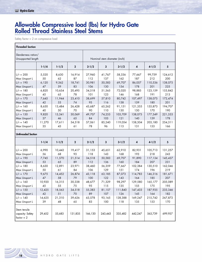
Stem AccessoriesHydro Gate Stem SplicesStems must be spliced when their length exceeds standardcommercially available stock lengths of rounds and to achieve apractical length for shipment from factory to the job sitewithout damage during handling. Also, lengths of stem must beconvenient for installation without bending. Placement of stemguides, lifts, or other structural configurations may necessitateshorter or longer lengths of stem.
For stems that need to be joined, splices or couplings must beused. The material for these splices should be of the same typeas that used for the stem. It must be of sufficient strength, ofequal or greater corrosion resistance and have the ability to beeasily machined. Hydro Gate splices meet these design criteria.Materials are of the same type as that provided for the stems.
Hydro Gate splices are furnished with interior threads tomatch those on the ends of sections of stems to be joined. Thisthreaded connection ensures precise stem alignment, and thethreads take the thrust developed during opening and closingof the gate. Each end of the stem that is to be joined isscrewed halfway into the threaded stem splice, is locked inplace by use of a key, and is welded or is pinned and welded.
A bolted steel stem splice is available. These are commonlyused in the oil-encased stem combinations of threaded andbolted, or bored and bolted may be used for field coupling toodd-size configurations on existing stems. The top end of thesplice is slipped into the bottom end of the stem, is carefullyaligned, and then welded. The bottom end of the splice andthe stem sections to be joined are connected with bolts or pins.
HydroGate
19H Y D R O G A T E L I F T S
Figure 5-18Stem Splice
HydroGate
20 H Y D R O G A T E L I F T S
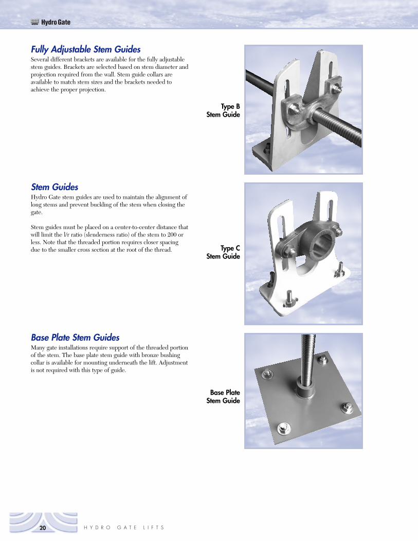
Fully Adjustable Stem GuidesSeveral different brackets are available for the fully adjustablestem guides. Brackets are selected based on stem diameter andprojection required from the wall. Stem guide collars areavailable to match stem sizes and the brackets needed toachieve the proper projection.
Stem GuidesHydro Gate stem guides are used to maintain the alignment oflong stems and prevent buckling of the stem when closing thegate.
Stem guides must be placed on a center-to-center distance thatwill limit the l/r ratio (slenderness ratio) of the stem to 200 orless. Note that the threaded portion requires closer spacingdue to the smaller cross section at the root of the thread.
Base Plate Stem GuidesMany gate installations require support of the threaded portionof the stem. The base plate stem guide with bronze bushingcollar is available for mounting underneath the lift. Adjustmentis not required with this type of guide.
Type BStem Guide
Type CStem Guide
Base PlateStem Guide
Hydro Gate furnishes one-piece or two-piece stem guidecollars. A one-piece collar requires that it be placed on thestem before it is joined to the next stem section or as the lift isinstalled. Two-piece collars can be installed on the stem after itis in place and facilitate removal of the collar and of the stem ifthis is necessary at a future date.
The stem guide collar is “fully adjustable” because it can beadjusted in two directions. Lateral adjustment parallel to thewall is obtained by slotted holes in the back of the bracket.Adjustment from the wall is obtained by long perpendicularslotted holes in the top of the bracket. The stem guide collarattaches through these perpendicular holes and allows forpositioning of the collar. The smaller Type B guides areprovided with two anchor bolts each for attaching the bracketto the vertical wall. They are usually used in smaller gates.
The larger, fully adjustable Type C guide has a larger bracket.Since the projection from the wall is considerably greater onthese guides, four anchor bolts are required for firmattachment. This type of bracket is used with medium andlarger size gates requiring stems 2-1/2 in. in diameter andlarger.
Bronze Bushing CollarsThe one-piece stem guide collar that supports the stem can beeither bronze bushed or cast iron. The bronze bushing isrecommended for lower friction between stem and collar. The
HydroGate
21H Y D R O G A T E L I F T S
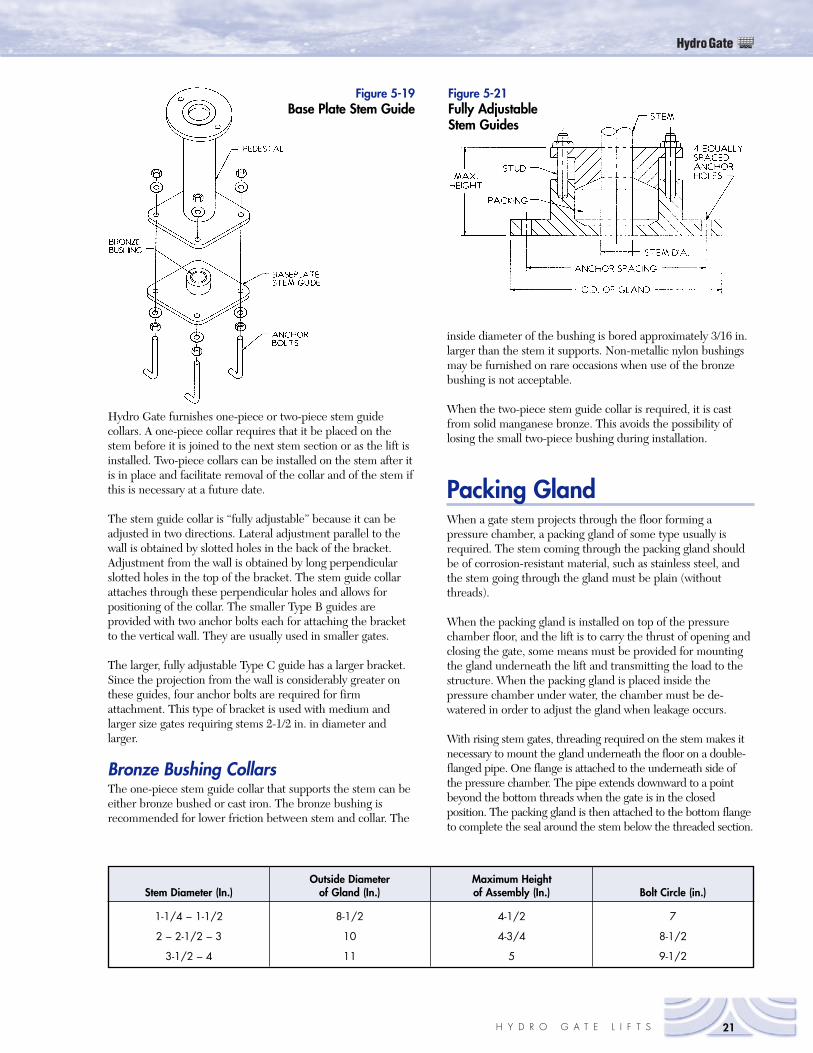
Figure 5-21Fully AdjustableStem Guides
Outside Diameter Maximum HeightStem Diameter (In.) of Gland (In.) of Assembly (In.) Bolt Circle (in.)
1-1/4 – 1-1/2 8-1/2 4-1/2 7
2 – 2-1/2 – 3 10 4-3/4 8-1/2
3-1/2 – 4 11 5 9-1/2
Figure 5-19Base Plate Stem Guide
inside diameter of the bushing is bored approximately 3/16 in.larger than the stem it supports. Non-metallic nylon bushingsmay be furnished on rare occasions when use of the bronzebushing is not acceptable.
When the two-piece stem guide collar is required, it is castfrom solid manganese bronze. This avoids the possibility oflosing the small two-piece bushing during installation.
Packing GlandWhen a gate stem projects through the floor forming apressure chamber, a packing gland of some type usually isrequired. The stem coming through the packing gland shouldbe of corrosion-resistant material, such as stainless steel, andthe stem going through the gland must be plain (withoutthreads).
When the packing gland is installed on top of the pressurechamber floor, and the lift is to carry the thrust of opening andclosing the gate, some means must be provided for mountingthe gland underneath the lift and transmitting the load to thestructure. When the packing gland is placed inside thepressure chamber under water, the chamber must be de-watered in order to adjust the gland when leakage occurs.
With rising stem gates, threading required on the stem makes itnecessary to mount the gland underneath the floor on a double-flanged pipe. One flange is attached to the underneath side ofthe pressure chamber. The pipe extends downward to a pointbeyond the bottom threads when the gate is in the closedposition. The packing gland is then attached to the bottom flangeto complete the seal around the stem below the threaded section.

Toll Free 800-678-8228303-287-8531 (fax)www.hydrogate.com
LIFT0906
Hydro GateYour Source for WaterControl Gates
Our mission is to be the leading water control gate manufacturer in the world, through continuous development of an organization which promotes extraordinary customerservice, superior engineering, qualityproducts and on-time delivery.