Embed Size (px)
Citation preview

30 AmpSolar ChargeController
SCC-30AB
Owner'sManual
Please read this manual before operating your charge controller.

2
1. Safety Instructions .............................................................................................. 3
2. General Description of PV / Solar System .......................................................... 5
3. General information - Batteries ...................................................................... 15
4. Introduction and Features ............................................................................... 28
5. Construction, Layout and Controls .................................................................. 33
6. Installation and Operation .............................................................................. 38
7. Troubleshooting ............................................................................................... 45
8. Specifications .................................................................................................... 47
9. Warranty ........................................................................................................... 49
INDEX
3
1SAFETY INSTRUCTIONS
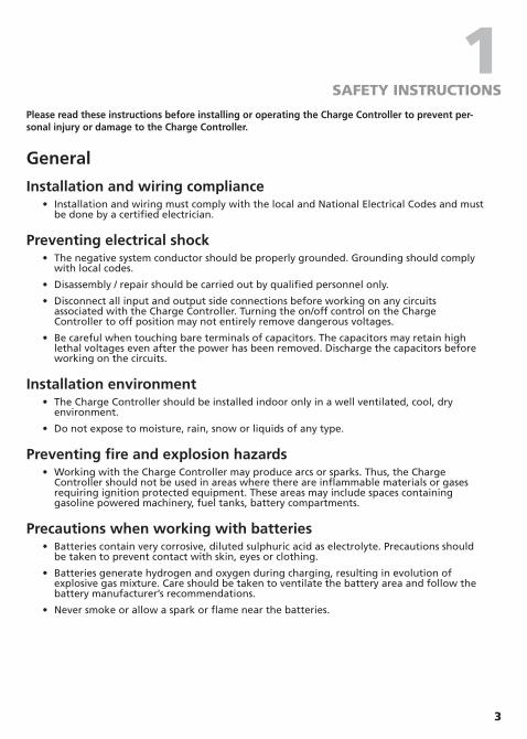
Please read these instructions before installing or operating the Charge Controller to prevent per-sonal injury or damage to the Charge Controller.
General
Installation and wiring compliance • Installation and wiring must comply with the local and National Electrical Codes and must
be done by a certified electrician.
Preventing electrical shock • The negative system conductor should be properly grounded. Grounding should comply
with local codes.
• Disassembly / repair should be carried out by qualified personnel only.
• Disconnect all input and output side connections before working on any circuits associated with the Charge Controller. Turning the on/off control on the Charge Controller to off position may not entirely remove dangerous voltages.
• Be careful when touching bare terminals of capacitors. The capacitors may retain high lethal voltages even after the power has been removed. Discharge the capacitors before working on the circuits.
Installation environment • The Charge Controller should be installed indoor only in a well ventilated, cool, dry
environment.
• Do not expose to moisture, rain, snow or liquids of any type.
Preventing fire and explosion hazards • Working with the Charge Controller may produce arcs or sparks. Thus, the Charge
Controller should not be used in areas where there are inflammable materials or gases requiring ignition protected equip ment. These areas may include spaces containing gasoline powered machinery, fuel tanks, battery compartments.
Precautions when working with batteries • Batteries contain very corrosive, diluted sulphuric acid as electrolyte. Precautions should
be taken to prevent contact with skin, eyes or clothing.
• Batteries generate hydrogen and oxygen during charging, resulting in evolution of explosive gas mixture. Care should be taken to ventilate the battery area and follow the battery manufacturer’s recommendations.
• Never smoke or allow a spark or flame near the batteries.
4
1SAFETY INSTRUCTIONS
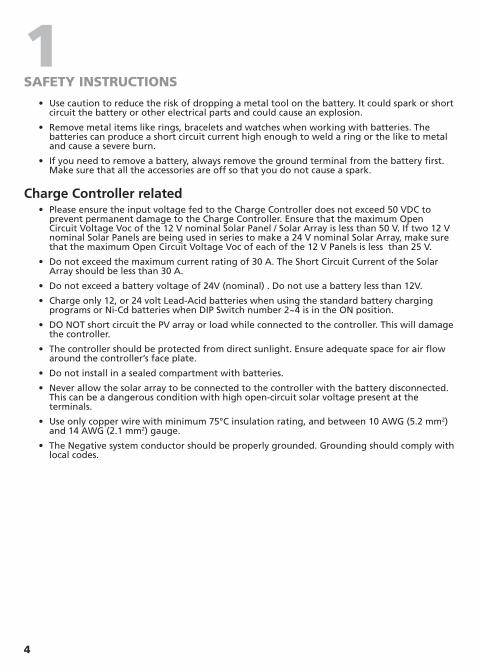
• Use caution to reduce the risk of dropping a metal tool on the battery. It could spark or short circuit the battery or other electrical parts and could cause an explosion.
• Remove metal items like rings, bracelets and watches when working with batteries. The batteries can produce a short circuit current high enough to weld a ring or the like to metal and cause a severe burn.
• If you need to remove a battery, always remove the ground terminal from the battery first. Make sure that all the accessories are off so that you do not cause a spark.
Charge Controller related • Please ensure the input voltage fed to the Charge Controller does not exceed 50 VDC to
prevent permanent damage to the Charge Controller. Ensure that the maximum Open Circuit Voltage Voc of the 12 V nominal Solar Panel / Solar Array is less than 50 V. If two 12 V nominal Solar Panels are being used in series to make a 24 V nominal Solar Array, make sure that the maximum Open Circuit Voltage Voc of each of the 12 V Panels is less than 25 V.
• Do not exceed the maximum current rating of 30 A. The Short Circuit Current of the Solar Array should be less than 30 A.
• Do not exceed a battery voltage of 24V (nominal) . Do not use a battery less than 12V.
• Charge only 12, or 24 volt Lead-Acid batteries when using the standard battery charging programs or Ni-Cd batteries when DIP Switch number 2~4 is in the ON position.
• DO NOT short circuit the PV array or load while connected to the controller. This will damage the controller.
• The controller should be protected from direct sunlight. Ensure adequate space for air flow around the controller’s face plate.
• Do not install in a sealed compartment with batteries.
• Never allow the solar array to be connected to the controller with the battery disconnected. This can be a dangerous condition with high open-circuit solar voltage present at the terminals.
• Use only copper wire with minimum 75°C insulation rating, and between 10 AWG (5.2 mm2) and 14 AWG (2.1 mm2) gauge.
• The Negative system conductor should be properly grounded. Grounding should comply with local codes.
5
2GENERAL DESCRIPTION OF PV / SOLAR SYSTEM
What is Photovoltaic (PV)?
The word ‘photo-voltaic’ is derived from two different words; the word ‘photos’, from the Greek, meaning light and the word ‘voltaic’ developed from the name of the Italian scientist, Volta, who studied electricity. This explains what a PV system does: it converts light energy from the sun into electrical energy.
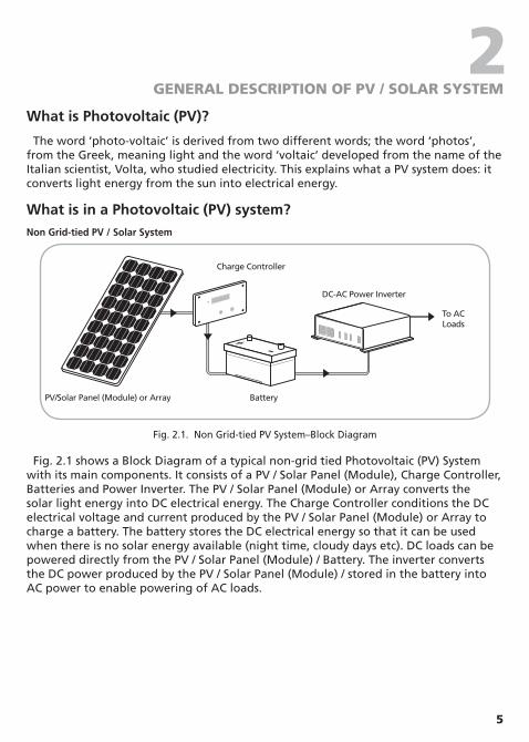
What is in a Photovoltaic (PV) system?Non Grid-tied PV / Solar System
PV/Solar Panel (Module) or Array
Charge Controller
Battery
DC-AC Power Inverter
To ACLoads
Solar Array
ChargeController/Protection
DC-AC Power Inverter
To ACLoads
Power toand from grid
Two-way Metering
Fig. 2.1. Non Grid-tied PV System–Block Diagram
Fig. 2.1 shows a Block Diagram of a typical non-grid tied Photovoltaic (PV) System with its main components. It consists of a PV / Solar Panel (Module), Charge Controller, Batteries and Power Inverter. The PV / Solar Panel (Module) or Array converts the solar light energy into DC electrical energy. The Charge Controller conditions the DC electrical voltage and current produced by the PV / Solar Panel (Module) or Array to charge a battery. The battery stores the DC electrical energy so that it can be used when there is no solar energy available (night time, cloudy days etc). DC loads can be powered directly from the PV / Solar Panel (Module) / Battery. The inverter converts the DC power produced by the PV / Solar Panel (Module) / stored in the battery into AC power to enable powering of AC loads.

6
2GENERAL DESCRIPTION OF PV / SOLAR SYSTEM
Grid-tied PV / Solar System
Fig. 2.2 shows a Block Diagram of a typical Grid-tied PV / Solar System. In this system, the Solar Panels (Modules) / Arrays directly feed to an inverter and the inverter is connected to an Electricity Transmission and Distribution System (referred to as the Electricity Grid) such that the system can draw on the Grid’s reserve capacity in times of need, and feed electricity back into the Grid during times of excess production.
PV/Solar Panel (Module) or Array
Charge Controller
Battery
DC-AC Power Inverter
To ACLoads
Solar Array
ChargeController/Protection
DC-AC Power Inverter
To ACLoads
Power toand from grid
Two-way Metering
Fig. 2.2. Grid-tied PV / Solar System – Block Diagram
In order to safely transmit electricity to your loads and to comply with your power provider’s grid-connection requirements, you may need the following additional items:
• Power conditioning equipment.
• Safety equipment.
• Meters and instrumentation.
7
2GENERAL DESCRIPTION OF PV / SOLAR SYSTEM
PV / Solar Cell
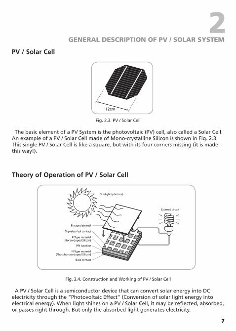
12cm
Fig. 2.3. PV / Solar Cell
The basic element of a PV System is the photovoltaic (PV) cell, also called a Solar Cell. An example of a PV / Solar Cell made of Mono-crystalline Silicon is shown in Fig. 2.3. This single PV / Solar Cell is like a square, but with its four corners missing (it is made this way!).
Theory of Operation of PV / Solar Cell
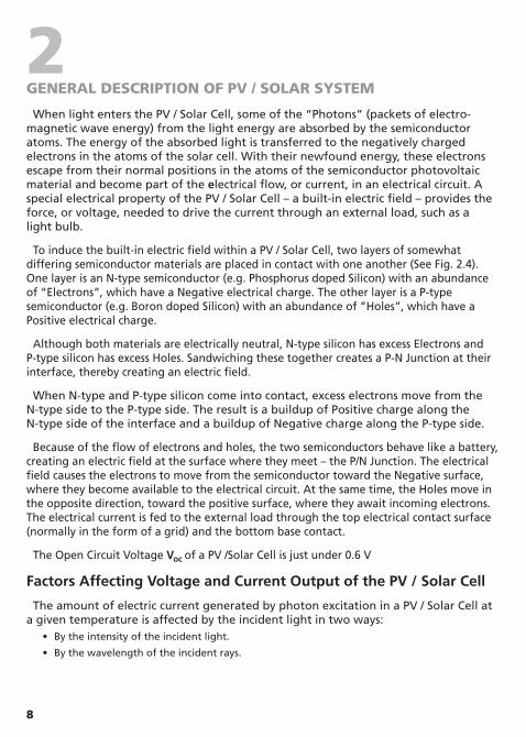
Sunlight (photons)
External circuit
Encapsulate seal
Top electrical contact
P-Type material(Boran-doped Silicon)
N-Type material(Phosphorous-doped Silicon)
P/N junction
Base contact
Fig. 2.4. Construction and Working of PV / Solar Cell
A PV / Solar Cell is a semiconductor device that can convert solar energy into DC electricity through the “Photovoltaic Effect” (Conversion of solar light energy into electrical energy). When light shines on a PV / Solar Cell, it may be reflected, absorbed, or passes right through. But only the absorbed light generates electricity.
8
2GENERAL DESCRIPTION OF PV / SOLAR SYSTEM
When light enters the PV / Solar Cell, some of the “Photons” (packets of electro-magnetic wave energy) from the light energy are absorbed by the semiconductor atoms. The energy of the absorbed light is transferred to the negatively charged electrons in the atoms of the solar cell. With their newfound energy, these electrons escape from their normal positions in the atoms of the semiconductor photovoltaic material and become part of the electrical flow, or current, in an electrical circuit. A special electrical property of the PV / Solar Cell – a built-in electric field – provides the force, or voltage, needed to drive the current through an external load, such as a light bulb.
To induce the built-in electric field within a PV / Solar Cell, two layers of somewhat differing semiconductor materials are placed in contact with one another (See Fig. 2.4). One layer is an N-type semiconductor (e.g. Phosphorus doped Silicon) with an abundance of “Electrons”, which have a Negative electrical charge. The other layer is a P-type semiconductor (e.g. Boron doped Silicon) with an abundance of ”Holes”, which have a Positive electrical charge.
Although both materials are electrically neutral, N-type silicon has excess Electrons and P-type silicon has excess Holes. Sandwiching these together creates a P-N Junction at their interface, thereby creating an electric field.
When N-type and P-type silicon come into contact, excess electrons move from the N-type side to the P-type side. The result is a buildup of Positive charge along the N-type side of the interface and a buildup of Negative charge along the P-type side.
Because of the flow of electrons and holes, the two semiconductors behave like a battery, creating an electric field at the surface where they meet – the P/N Junction. The electrical field causes the electrons to move from the semiconductor toward the Negative surface, where they become available to the electrical circuit. At the same time, the Holes move in the opposite direction, toward the positive surface, where they await incoming electrons. The electrical current is fed to the external load through the top electrical contact surface (normally in the form of a grid) and the bottom base contact.
The Open Circuit Voltage Voc of a PV /Solar Cell is just under 0.6 V
Factors Affecting Voltage and Current Output of the PV / Solar Cell
The amount of electric current generated by photon excitation in a PV / Solar Cell at a given temperature is affected by the incident light in two ways:
• By the intensity of the incident light.
• By the wavelength of the incident rays.

9
2GENERAL DESCRIPTION OF PV / SOLAR SYSTEM
The materials used in PV / Solar Cells have different spectral responses to incident
light, and exhibit a varying sensitivity with respect to the absorption of photons at given wavelengths. Each semiconductor material will have an incident radiation threshold frequency, below which no electrons will be subjected to the photovoltaic effect. Above the threshold frequency, the kinetic energy of the emitted photoelectron varies according to the wavelength of the incident radiation, but has no relation to the light intensity. Increasing light intensity will proportionally increase the rate of photoelectron emission in the photovoltaic material. In actual applications, the light absorbed by a PV cell will be a combination of direct solar radiation, as well as diffused light bounced off of surrounding surfaces. PV / Solar Cells are usually coated with anti-reflective material so that they absorb the maximum amount of radiation possible.
The output current of the PV / Solar Panel (Module) can increase due to what is known as the “Edge of the Cloud Effect”. As the sun moves into a hole between the clouds, your solar panels will see full direct sunlight combined with reflected light from the clouds! They will absorb more energy than they could on a cloudless day! Thus, a factor of 1.25 times the Short Circuit Current Isc is recommended when sizing the current capacity of the Charge Controller.
The output current of the PV / Solar Cell has a positive Temperature Coefficient – The output current increases with the rise of temperature. However, it is negligible – less than 0.1 % / °C of the Short Circuit Current Isc.
The output voltage of the PV / Solar Cell has a Negative Temperature Coefficient – The output voltage increases with decrease in temperature. For example, a Silicon Cell has a Temperature Coefficient of – 2.3 mV / °C / Cell. Hence, during cold winter days, the voltage will rise. As a Rule of Thumb, the voltage rating of the Charge Controller should be sized as 1.25 times the Open Circuit Voltage rating Voc of the PV / Solar Panel (Module) to ensure that the Charge Controller is not damaged due to over-voltage.
10
2GENERAL DESCRIPTION OF PV / SOLAR SYSTEM
PV Cell Types
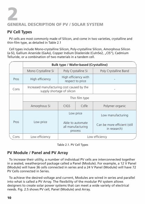
PV cells are most commonly made of Silicon, and come in two varieties, crystalline and thin-film type, as detailed in Table 2.1
Cell types include Mono-crystalline Silicon, Poly-crystalline Silicon, Amorphous Silicon (a-Si), Gallium Arsenide (GaAs), Copper Indium Diselenide (CuInSe2, „CIS“), Cadmium Telluride, or a combination of two materials in a tandem cell.
Bulk type / Wafer-based (Crystalline)
Mono Crystalline Si Poly Crystalline Si Poly Crystalline Band
Pros High efficiencyHigh efficiency with
respect to price-
ConsIncreased manufacturing cost caused by the
supply shortage of silicon-
Thin film type
Amorphous Si CIGS CdTe Polymer organic
Pros Low price
Low price
Able to automate all manufacturing
process
Low manufacturing
Can be more efficient (still in research)
Cons Low efficiency Low efficiency
Table 2.1. PV Cell Types
PV Module / Panel and PV Array
To increase their utility, a number of individual PV cells are interconnected together in a sealed, weatherproof package called a Panel (Module). For example, a 12 V Panel (Module) will have 36 cells connected in series and a 24 V Panel (Module) will have 72 PV Cells connected in Series.
To achieve the desired voltage and current, Modules are wired in series and parallel into what is called a PV Array. The flexibility of the modular PV system allows designers to create solar power systems that can meet a wide variety of electrical needs. Fig. 2.5 shows PV cell, Panel (Module) and Array.

11
2GENERAL DESCRIPTION OF PV / SOLAR SYSTEM
Cell
Module
Array
Fig. 2.5. PV cell, Module and Array
The cells are very thin and fragile so they are sandwiched between a transparent front sheet, usually glass, and a backing sheet, usually glass or a type of tough plastic. This protects them from breakage and from the weather. An aluminum frame is fitted around the module to enable easy fixing to a support structure.
The picture in Fig. 2.6 shows a small part of a Module with cells in it. It has a glass front, a backing plate and a frame around it.
Aluminumframe
Glassfront
BackingSheet
PV Cell
Fig. 2.6. Construction of a typical Mono-crystalline PV / Solar Panel

12
2GENERAL DESCRIPTION OF PV / SOLAR SYSTEM
Bypass Diodes
As mentioned, PV / Solar cells are wired in series and in parallel to form a PV / Solar Panel (Module). The number of series cells indicates the voltage of the Panel (Module), whereas the number of parallel cells indicates the current. If many cells are connected in series, shading of individual cells can lead to the destruction of the shaded cell or of the lamination material, so the Panel (Module) may blister and burst. To avoid such an operational condition, Bypass Diodes are connected anti-parallel to the solar cells as in Fig. 2.7. As a consequence, larger voltage differences cannot arise in the reverse-current direction of the solar cells. In practice, it is sufficient to connect one bypass diode for every 15-20 cells. Bypass diodes also allow current to flow through the PV module when it is partially shaded, even if at a reduced voltage and power. Bypass diodes do not cause any losses, because under normal operation, current does not flow through them.
+-
load
bypass diodesA K
Figure 2.7. Parallel PV cell with bypass diodes
Current (I), Voltage (V) and Power (P) Curves of a PV / Solar Panel (Module) and how the PV / Solar Panel (Module) is rated - Voc , Vmp , Isc , Imp , Pmax
Fig. 2.8. Current (I), Voltage (V) and Power (P) Curves

13
2GENERAL DESCRIPTION OF PV/SOLAR SYSTEM
A Current (I) versus Voltage (V) Curve of a PV / Solar Module (“I-V” Curve) shows the possible combinations of its current and voltage outputs. A typical I-V curve for a 12 V Module is shown in Fig. 2.8.
The power in a DC electrical circuit is the product of the voltage and the current. Mathematically,
• Power (P) in Watts (W) = The Current (I) in Amperes (A) X the Voltage (V) in Volts (V)
i.e. W = V x A
A PV / Solar Cell or a Panel (Module) produces its maximum current when there is no resistance in the circuit, i.e. when there is a short circuit between its Positive and Negative terminals. This maximum current is known as the Short Circuit Current and is abbreviated as Isc. When the Cell / Panel (Module) is shorted, the voltage in the circuit is zero.
Conversely, the maximum voltage occurs when there is a break in the circuit. This is called the Open Circuit Voltage (Voc). Under this condition, the resistance is infinitely high and there is no current, since the circuit is incomplete. Typical value of the open-circuit voltage is located about 0.5 – 0.6 V for Crystalline Cells and 0.6 – 0.9 V for Amorphous Cells.
These two extremes in load resistance, and the whole range of conditions in between them, are depicted on the I-V Curve. Current, expressed in Amps, is on the vertical Y-axis. Voltage, in Volts, is on the horizontal X-axis.
The power available from a photovoltaic device at any point along the curve is just the product of Current (I) in Amps (A) and Voltage (V) in Volts (V) at that point and is expressed in Watts. At the short circuit current point, the power output is zero, since the voltage is zero. At the open circuit voltage point, the power output is also zero, but this time it is because the current is zero.
Maximum Power Point and Rated Power of PV / Solar Panel (Module)
There is a point on the knee of the I-V Curve where the maximum power output is located and this point is called the Maximum Power Point (MPP). The voltage and current at this Maximum Power Point are designated as Vmp and Imp.
The values of Vmp and Imp can be estimated from Voc and Isc as follows:
Vmp ≈ (0.75 – 0.9) Voc
Imp ≈ (0.85 – 0.95) Isc
14
2GENERAL DESCRIPTION OF PV/SOLAR SYSTEM
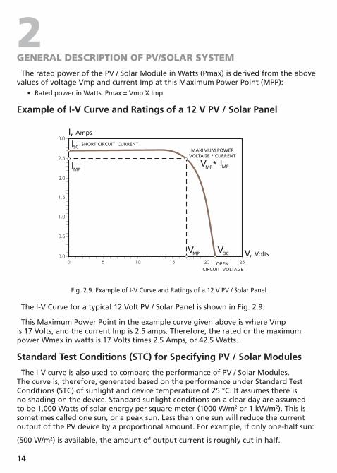
The rated power of the PV / Solar Module in Watts (Pmax) is derived from the above values of voltage Vmp and current Imp at this Maximum Power Point (MPP):
• Rated power in Watts, Pmax = Vmp X Imp
Example of I-V Curve and Ratings of a 12 V PV / Solar Panel
Fig. 2.9. Example of I-V Curve and Ratings of a 12 V PV / Solar Panel
The I-V Curve for a typical 12 Volt PV / Solar Panel is shown in Fig. 2.9.
This Maximum Power Point in the example curve given above is where Vmp is 17 Volts, and the current Imp is 2.5 amps. Therefore, the rated or the maximum power Wmax in watts is 17 Volts times 2.5 Amps, or 42.5 Watts.
Standard Test Conditions (STC) for Specifying PV / Solar Modules
The I-V curve is also used to compare the performance of PV / Solar Modules. The curve is, therefore, generated based on the performance under Standard Test Conditions (STC) of sunlight and device temperature of 25 °C. It assumes there is no shading on the device. Standard sunlight conditions on a clear day are assumed to be 1,000 Watts of solar energy per square meter (1000 W/m2 or 1 kW/m2). This is sometimes called one sun, or a peak sun. Less than one sun will reduce the current output of the PV device by a proportional amount. For example, if only one-half sun:
(500 W/m2) is available, the amount of output current is roughly cut in half.
15
3GENERAL INFORMATION: BATTERIES
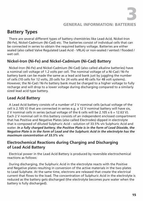
Battery TypesThere are several different types of battery chemistries like Lead-Acid, Nickel-Iron
(Ni-Fe), Nickel-Cadmium (Ni-Cad) etc. The batteries consist of individual cells that can be connected in series to obtain the required battery voltage. Batteries are either sealed (also called Valve Regulated Lead Acid - VRLA) or non-sealed / vented / flooded / wet cell.
Nickel-Iron (Ni-Fe) and Nickel-Cadmium (Ni-Cad) Battery
Nickel-Iron (Ni-Fe) and Nickel-Cadmium (Ni-Cad) (also called alkaline batteries) have a nominal cell voltage of 1.2 volts per cell. The nominal voltage of a Ni-Cad / Ni-Fe battery bank can be made the same as a lead acid bank just by juggling the number of cells (10 cells for 12 volts, 20 cells for 24 volts and 40 cells for 48 volt systems). However, the Ni-Cad / Ni-Fe battery bank must be charged to a higher voltage to fully recharge and will drop to a lower voltage during discharging compared to a similarly sized lead acid type battery.
Lead Acid Battery
A Lead Acid battery consists of a number of 2 V nominal cells (actual voltage of the cell is 2.105 V) that are connected in series e.g. a 12 V nominal battery will have six, 2 V nominal cells in series (actual voltage of the 6 cells will be 2.105 x 6 = 12.63 V). Each 2 V nominal cell in this battery consists of an independent enclosed compartment that has Positive and Negative Plates (also called Electrodes) dipped in electrolyte that is composed of diluted Sulphuric Acid – solution of 33.5% v/v Sulphuric Acid and water. In a fully charged battery, the Positive Plate is in the form of Lead Dioxide, the Negative Plate is in the form of Lead and the Sulphuric Acid in the electrolyte has the maximum concentration of 33.5% v/v.
Electrochemical Reactions during Charging and Discharging of Lead Acid Battery
Electrical power in the Lead Acid Battery is produced by reversible electrochemical reactions as follows:
During discharging, the Sulphuric Acid in the electrolyte reacts with the Positive and Negative plates resulting in conversion of the active materials in the two plates to Lead Sulphate. At the same time, electrons are released that create the electrical current that flows to the load. The concentration of Sulphuric Acid in the electrolyte is reduced as the battery gets discharged (the electrolyte becomes pure water when the battery is fully discharged).

16
3GENERAL INFORMATION: BATTERIES
During charging, reverse electrochemical reactions take place. Under the influence of the charging voltage fed to the battery by the external battery charger / charge controller, electrons are fed back to the battery and the Lead Sulphate at the Positive and Negative Plates is converted back to Lead Dioxide at the Positive Plate and Lead at the Negative Plate and the concentration of Sulphuric Acid is restored (will revert to 33.5% v/v when the battery is fully charged).
Gassing due to Excessive Overcharging
During charging, the battery is required to be charged in a controlled manner in the final Absorption Stage (2.4 V per cell at 25 ºC / 77 ºF or 14.4 V for a 12 V battery at 25 ºC / 77 ºF) that restores the last 20% to 30% of the capacity. On completion of this stage of charging, the Lead Sulphate at the Positive and Negative Plates is fully converted back to Lead Dioxide at the Positive Plate and Lead at the Negative Plate. Any further charging at this voltage or higher than this voltage results in electrolysis of water in the electrolyte to Hydrogen and Oxygen and this undesirable condition contributes to waste of energy. This process is known as “gassing”. Gassing is also produced during the timed Equalization Stage (performed only for vented /flooded / wet cell batteries) when the battery is intentionally overcharged (2.5 to 2.6 V per cell / 15 to 15.6 V for 12 V batteries) so that weaker cells are brought up to the full charge too (equalized).
Non-sealed / vented / flooded / wet cell batteries have open vents to release Hydrogen and Oxygen produced during gassing. The above un-intentional electrolysis of water during overcharging results in loss of water and reduces the level of the electrolyte in this type of batteries. When the level of the electrolyte is reduced, the upper portion of the plates in the cells will not be immersed in the electrolyte and will result in loss of battery capacity. Hence, these types of batteries are required to be topped up with distilled water periodically to ensure that the plates in the cells are fully immersed in the electrolyte. Some non-sealed / vented / flooded / wet cell batteries come with catalytic caps to recombine any emitted Hydrogen and Oxygen.
Sealed / VRLA batteries are designed to recombine the Hydrogen and Oxygen back into water and hence, Sealed / VRLA batteries are not required to be topped up with distilled water. That is why these batteries are also called maintenance free batteries. Sealed / VRLA batteries use safety valves to release any excessive gas pressure built up inside the battery due to malfunction or overheating. If this happens (e.g., by overcharging) the valve vents the gas and normalizes the pressure, producing a characteristic acid smell. Valves can sometimes fail however, if dirt and debris accumulate, allowing pressure to build up that will result in damage to the battery.

17
3GENERAL INFORMATION: BATTERIES
Sealed Lead Acid (SLA) or Valve regulated Lead Acid (VRLA) Batteries
Sealed Lead Acid (SLA) batteries or Valve Regulated Lead Acid (VRLA) batteries can either be Gel Cell or AGM (Absorbed Glass Mat). In a Gel Cell battery, the electrolyte is in the form of a gel. In AGM (Absorbed Glass Mat) battery, the electrolyte is soaked in Glass Mat. In both these types, the electrolyte is immobile. There are no refill caps and the battery is totally sealed. Hydrogen and Oxygen released during the charging process is not allowed to escape and is recombined inside the battery. Hence, there is no water loss and the batteries are maintenance free. These batteries have safety valves on each cell to release excessive pressure that may be built up inside the cell. The Gel Cell is the least affected by temperature extremes, storage at low state of charge and has a low rate of self discharge. An AGM battery will handle overcharging slightly better than the Gel Cell.
Non Sealed (Vented / Flooded / Wet Cell) Lead acid Batteries
In a non-sealed / vented / flooded / wet cell battery, each individual cell compartment has a refill cap that is used to top up the cell with distilled water and to measure the specific gravity of the electrolyte using a hydrometer. When fully charged, each individual cell has a voltage of approximately 2.105 V and electrolyte specific gravity of 1.265. As the cell discharges, its voltage and specific gravity drop. Thus, a healthy, fully charged, 12 V nominal battery with each of the 6 cells fully charged to 2.105 V will measure a standing voltage of 12.63 V at 25 ºC / 77 ºF. Also, in a healthy battery, all the individual cells will have the same voltage and same specific gravity. If there is a substantial difference in the voltages (0.2 V or higher) and specific gravities of the individual cells, the cells will require equalization.
Construction of Battery Cell Plates - Lead Antimony and Lead Calcium Batteries
During construction, both the Positive and the Negative plates are similar. Both the plates consist of a rectangular grid made out of alloyed Lead with rectangular holes in it as shown in Fig 3.1 below:
Fig 3.1. Grid structure of Positive and Negative Plates in a Lead Acid Battery

18
3GENERAL INFORMATION: BATTERIES
The holes in the grid of the plates are filled with a paste of active material made out of a mixture of Red Lead and 33% dilute Sulphuric Acid (different manufacturers use modified mixtures). The paste is pressed into the holes in the grid. This paste remains porous and allows the Sulphuric Acid in the electrolyte to react with the lead inside the plate increasing the surface area many fold. At this stage, the Positive and Negative plates are identical. Once dry, the plates are then stacked together with suitable separators and inserted in the battery container. After the electrolyte has been added to the cell, the cell is given its first “Forming Charge”. During this “Forming Charge”, the Lead paste in the Positive plate gradually turns to Lead Dioxide (chocolate brown color), and the Lead paste in the Negative plate turns to Sponge Lead (slate gray color). Such charged cell is ready to be used.
The above grid structure of the plates is made from a Lead alloy. A pure Lead grid structure is not strong enough by itself to stand vertically while supporting the active material. Other metals in small quantities are alloyed with Lead for added strength and improved electrical properties. The most commonly alloyed metals are Antimony, Calcium, Tin, and Selenium.
The two most common alloys used today to harden the grid are Antimony and Calcium. Batteries with these types of grids are sometimes called “Lead-Antimony” and & “Lead-Calcium” batteries. Tin is added to Lead-Calcium grids to improve cyclability
The major differences between batteries with Lead-Antimony and Lead-Calcium grids are as follows:
• Lead-Antimony batteries can be deep cycled more times than Lead-Calcium batteries.
• Flooded Lead-Antimony batteries require more frequent maintenance as they near end-of-life since they use an increasing amount of water and require periodic equalization charges.
• Lead-Calcium batteries have lower self-discharge rates and therefore, will draw less current while kept in storage
SLI (Starting, Lighting, Ignition) Batteries
Everybody is familiar with the SLI batteries that are used for automotive starting, lighting, ignition and powering vehicular accessories. SLI batteries are designed to produce high power in short bursts for cranking. SLI batteries use lots of thin plates to maximize the surface area of the battery for providing very large bursts of current (also specified as Cranking Amps). This allows very high starting current but causes the plates to warp when the battery is cycled. Vehicle starting typically discharges 1%-3% of a healthy SLI battery’s capacity. The automotive SLI battery is not designed for repeated deep discharge where up to 80 % of the battery capacity is discharged and then recharged. If an SLI battery is used for this type of deep discharge application, its useful service life will be drastically reduced.

19
3GENERAL INFORMATION: BATTERIES
This type of battery is not recommended for the storage of energy for inverter applications. However, they are recommended as starting battery for the back-up generator.
Deep Cycle Lead Acid Batteries
Deep cycle batteries are designed with thick-plate electrodes to serve as primary power sources, to have a constant discharge rate, to have the capability to be deeply discharged up to 80 % capacity and to repeatedly accept recharging. They are marketed for use in recreation vehicles (RV), boats and electric golf carts – so they may be referred to as RV batteries, marine batteries or golf cart batteries.
Units of Battery Capacity – Ampere Hours (AH) and Reserve Minutes (RC)
The battery capacity is the measure of the electrical energy the battery can store and deliver to a load. It is determined by the amount of current any given battery can deliver over a stipulated period of time. The energy rating is expressed in Ampere Hours (AH). As a bench mark, the battery industry rates batteries at 20 Hour rate i.e., the number of Amperes of current the battery can deliver for 20 Hours at 80 ºF (26.7 ºC) till the voltage drops to 10.5 Volts for 12 V battery and 21 V for 24 V battery. For example, a 100 AH battery will deliver 5 Amperes for 20 Hours.
Battery capacity is also expressed as Reserve Capacity (RC) in minutes. Reserve capacity is the time in minutes for which the battery can deliver 25 Amperes at 80 ºF (26.7 ºC) till the voltage drops to 10.5 Volts for 12 V battery and 21 V for 24 V battery. Approximate relationship between the two units is as follows:
Capacity in AH = Reserve Capacity in RC minutes x 0.6
Typical Battery Sizes
The Table below shows details of some popular battery sizes:
BCI* GROUP BATTERy VOLTAGE, V BATTERy CAPACITy, AH
27 / 31 12 105
4 D 12 160
8D 12 225
GC2** 6 220
* Battery Council International ** Golf Cart
Table 3.1. Popular Battery Sizes
20
3GENERAL INFORMATION: BATTERIES
Reduction in Usable Capacity at Higher Discharge Rates
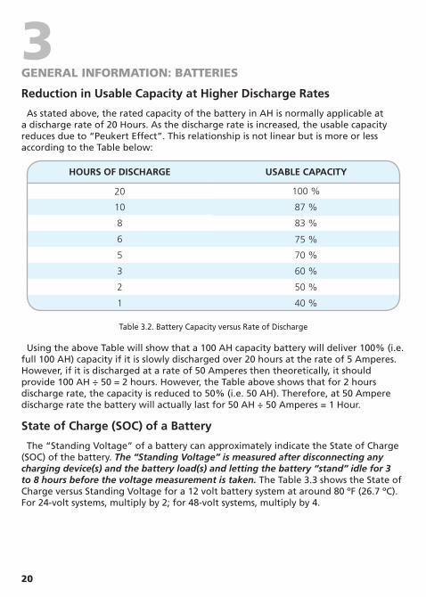
As stated above, the rated capacity of the battery in AH is normally applicable at a discharge rate of 20 Hours. As the discharge rate is increased, the usable capacity reduces due to “Peukert Effect”. This relationship is not linear but is more or less according to the Table below:
HOURS OF DISCHARGE USABLE CAPACITy
20 100 %
10 87 %
8 83 %
6 75 %
5 70 %
3 60 %
2 50 %
1 40 %
Table 3.2. Battery Capacity versus Rate of Discharge
Using the above Table will show that a 100 AH capacity battery will deliver 100% (i.e. full 100 AH) capacity if it is slowly discharged over 20 hours at the rate of 5 Amperes. However, if it is discharged at a rate of 50 Amperes then theoretically, it should provide 100 AH ÷ 50 = 2 hours. However, the Table above shows that for 2 hours discharge rate, the capacity is reduced to 50% (i.e. 50 AH). Therefore, at 50 Ampere discharge rate the battery will actually last for 50 AH ÷ 50 Amperes = 1 Hour.
State of Charge (SOC) of a Battery
The “Standing Voltage” of a battery can approximately indicate the State of Charge (SOC) of the battery. The “Standing Voltage” is measured after disconnecting any charging device(s) and the battery load(s) and letting the battery “stand” idle for 3 to 8 hours before the voltage measurement is taken. The Table 3.3 shows the State of Charge versus Standing Voltage for a 12 volt battery system at around 80 ºF (26.7 ºC). For 24-volt systems, multiply by 2; for 48-volt systems, multiply by 4.

21
3GENERAL INFORMATION: BATTERIES
PERCENTAGE OF FULL CHARGE
STANDING VOLTAGE OF 12 V NOMINAL BATTERy
CELL VOLTAGE (12 V BATTERy HAS 6 CELLS IN SERIES)
100% 12.63 V 2.105 V90% 12.6 V 2.10 V80% 12.5 V 2.08 V70% 12.3 V 2.05 V60% 12.2 V 2.03 V50% 12.1 V 2.02 V40% 12.0 V 2.00 V30% 11.8 V 1.97 V20% 11.7 V 1.95 V10% 11.6 V 1.93 V0% = / < 11.6 V = / < 1.93 V
Table 3.3. State of Charge versus Standing Voltage – 12 V Battery
Check the individual cell voltages. If the inter cell voltage difference is more than a 0.2 V, the battery will have to be equalized. Please note that only the non-sealed / vented / flooded / wet cell batteries are equalized. Do not equalize sealed / VRLA type of AGM or Gel Cell Batteries.
Battery Efficiency
A lead-acid battery has an efficiency of only 75% - 85%. The energy lost appears as heat and warms the battery. This means that the Ampere Hour (AH) energy required to charge a battery to its full rated capacity will be approximately 120% to 130% higher than the AH capacity rating of the battery.
Depth of Discharge and Battery Life
The more deeply a battery is discharged on each cycle, the shorter the battery life. Using more batteries than the minimum required will result in longer life for the battery bank. A typical life cycle chart is given in the Table below:
DEPTH OF DISCHARGE % OF AH CAPACITy
CyCLE LIFE OF GROUP 27 / 31
CyCLE LIFE OF GROUP 8D
CyCLE LIFE OF GROUP GC2
10 1000 1500 380050 320 480 110080 200 300 675100 150 225 550
Table 3.4. Typical Cycle Life Chart
It is recommended that the depth of discharge should be limited to 50%.

22
3GENERAL INFORMATION: BATTERIES
Effect of Temperature on Battery Voltage
The temperature of the electrolyte affects the rate of chemical reactions in the batteries as well as the rate of diffusion and the resistivity of the electrolyte. Therefore, the charging characteristics of the battery will vary with temperature. This is nearly linear and the Voltage Coefficient of Temperature Change is normally taken as -3 mV to -5 mV / ºC / Cell. Please note that the Voltage Coefficient of Temperature Change is negative. This means that as the temperature rises, the charging voltage is required to be reduced and as the temperature is decreased, the charging voltage has to be increased.
All charging voltage set points are normally specified at 25 ºC / 77 ºF. In PV systems, battery temperatures often vary up to 15 ºC from the 25 ºC reference. The Absorption Voltage for a 12 V battery must then be adjusted as shown in the Table below or a controller with Temperature Sensor should be used (assuming Voltage Coefficient of Temperature Change as -5 mV / ºC / Cell or -30mV (.03 V) for a 6 cell, 12 V battery) :
BATTERy TEMPERATURE ABSORPTION VOLTAGE
40 ºC 13.95 V
25 ºC (Reference) 14.4 V (Reference)
10 ºC 14.85 V
In case temperature compensation is not provided, the warmer battery at 40 ºC will begin to heat and outgas at 13.95 V and will continue to overcharge until the non-compensated Absorption Voltage set point is reached (14.4 V). In cooler temperatures, the 10 ºC battery will experience severe undercharging, resulting in sulfation.
It is recommended that a battery charger / charge controller with a provision for temperature sensing and compensation should be used if the battery electrolyte temperature varies more than 5 ºC to 10 ºC (9 ºF to 18 ºF).
Self-discharge
The battery discharges itself even without any load connected to it. This effect is caused by secondary reactions at its electrodes and proceeds faster with higher temperature or in older batteries. Thermodynamic instability of the active materials and electrolytes as well as internal- and external short-circuits lead to capacity losses, which are defined as self-discharge. This loss should be small, particularly in respect of annual storage. Self discharge (% of loss of capacity per month) for various types of batteries is as follows:
• Lead Acid 3% to 4% • Ni-Cd 6% to 20% • Ni-Fe 40%

23
3GENERAL INFORMATION: BATTERIES
Loss of Battery Capacity at Low Temperatures
Batteries lose capacity in low temperatures. At 32 ºF (0 ºC), a battery will deliver about 70 to 80 % of its rated capacity at 80 ºF (26.7 ºC). If the electrolyte temperature of the battery bank is lower than 80 ºF (26.7 ºC), additional batteries will be needed to provide the same usable capacity. For very cold climates, an insulated / heated battery compartment is recommended.
Freezing of Electrolyte
For applications with low ambient temperature, the lead-acid battery must also be protected against freezing of the electrolyte. The risk of freezing depends on the state of charge. The chart given below illustrates the freezing limit as a function of the state of charge.
- 80°
- 60°
- 40°
- 20°
0°
0 20 40 60 80 100
State of charge [%]
Tem
pera
ture
[°C
]
slushy until hard
- 80°
- 60°
- 40°
- 20°
0°
0 20 40 60 80 100
State of charge [%]
Tem
pera
ture
[°C
]
slushy until hard
Series and Parallel Connection of Batteries
Series Connection
Solar Charge ControllerSCC30-AB (rear view)
PV + PV -BAT +BAT -
6V Battery 6V Battery
Battery 4 Battery 3
6V Battery
Battery 2
6V Battery
Battery 1
6V Battery
Cable “A”
Cable “B”
Fig. 3.2. Series Connection
When two or more batteries are connected in series, their voltages add up, but their AH capacity remains the same. Fig. 3.2 above shows 4 pieces of 6 V, 200 AH batteries connected in series to form a battery bank of 24 V with a capacity of 200 AH. The

24
3GENERAL INFORMATION: BATTERIES
Positive terminal of Battery 4 becomes the Positive terminal of the 24 V bank. The Negative terminal of Battery 4 is connected to the Positive terminal of Battery 3. The Negative terminal of Battery 3 is connected to the Positive terminal of Battery 2. The Negative terminal of Battery 2 is connected to the Positive terminal of Battery 1. The Negative terminal of Battery 1 becomes the Negative terminal of the 24 V battery bank.
Parallel Connection
Solar Charge ControllerSCC30-AB (rear view)
PV + PV -BAT +BAT -
12V Battery 12V Battery 12V Battery 12V Battery
Battery 1 Battery 3Battery 2 Battery 4Cable “A”
Cable “B”
Fig. 3.3. Parallel Connection
When two or more batteries are connected in parallel, their voltage remains the same but their AH capacities add up. Fig. 3.3 above shows 4 pieces of 12 V, 100 AH batteries connected in parallel to form a battery bank of 12 V with a capacity of 400 AH. The four Positive terminals of Batteries 1 to 4 are paralleled (connected together) and this common Positive connection becomes the Positive terminal of the 12 V bank. Similarly, the four Negative terminals of Batteries 1 to 4 are paralleled (connected together) and this common Negative connection becomes the Negative terminal of the 12 V battery bank.
Series – Parallel Connection
Solar Charge ControllerSCC30-AB (rear view)
PV + PV -BAT +BAT -
6V Battery 6V Battery 6V Battery 6V Battery
String 1 String 2
Battery 1 Battery 3Battery 2 Battery 4
Cable “A”
Cable “B”
Fig. 3.4. Series-Parallel Connection
25
3GENERAL INFORMATION: BATTERIES
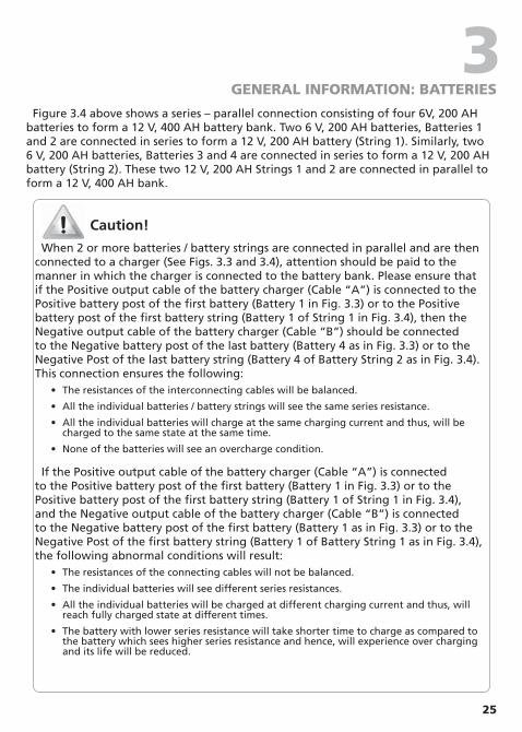
Figure 3.4 above shows a series – parallel connection consisting of four 6V, 200 AH batteries to form a 12 V, 400 AH battery bank. Two 6 V, 200 AH batteries, Batteries 1 and 2 are connected in series to form a 12 V, 200 AH battery (String 1). Similarly, two 6 V, 200 AH batteries, Batteries 3 and 4 are connected in series to form a 12 V, 200 AH battery (String 2). These two 12 V, 200 AH Strings 1 and 2 are connected in parallel to form a 12 V, 400 AH bank.
Caution!
When 2 or more batteries / battery strings are connected in parallel and are then connected to a charger (See Figs. 3.3 and 3.4), attention should be paid to the manner in which the charger is connected to the battery bank. Please ensure that if the Positive output cable of the battery charger (Cable “A”) is connected to the Positive battery post of the first battery (Battery 1 in Fig. 3.3) or to the Positive battery post of the first battery string (Battery 1 of String 1 in Fig. 3.4), then the Negative output cable of the battery charger (Cable “B”) should be connected to the Negative battery post of the last battery (Battery 4 as in Fig. 3.3) or to the Negative Post of the last battery string (Battery 4 of Battery String 2 as in Fig. 3.4). This connection ensures the following:
• The resistances of the interconnecting cables will be balanced.
• All the individual batteries / battery strings will see the same series resistance.
• All the individual batteries will charge at the same charging current and thus, will be charged to the same state at the same time.
• None of the batteries will see an overcharge condition.
If the Positive output cable of the battery charger (Cable “A”) is connected to the Positive battery post of the first battery (Battery 1 in Fig. 3.3) or to the Positive battery post of the first battery string (Battery 1 of String 1 in Fig. 3.4), and the Negative output cable of the battery charger (Cable “B”) is connected to the Negative battery post of the first battery (Battery 1 as in Fig. 3.3) or to the Negative Post of the first battery string (Battery 1 of Battery String 1 as in Fig. 3.4), the following abnormal conditions will result:
• The resistances of the connecting cables will not be balanced.
• The individual batteries will see different series resistances.
• All the individual batteries will be charged at different charging current and thus, will reach fully charged state at different times.
• The battery with lower series resistance will take shorter time to charge as compared to the battery which sees higher series resistance and hence, will experience over charging and its life will be reduced.
26
3GENERAL INFORMATION: BATTERIES
Sizing the Inverter Battery Bank
One of the most frequently asked question is, “how long will the batteries last?” This question cannot be answered without knowing the size of the battery system and the load on the inverter. Usually this question is turned around to ask “How long do you want your load to run?” and then specific calculations can be done to determine the proper battery bank size.
There are a few basic formulae and estimation rules that are used:
Formula 1 Power in Watts (W) = Voltage in Volts (V) x Current in Amperes (A). Formula 2 For an inverter running from a 12 V battery system, the DC current
required from the 12 V batteries is the AC power delivered by the inverter to the load in Watts (W) divided by 10 & for an inverter running from a 24 V battery system, the DC current required from the 24 V batteries is the AC power delivered by the inverter to the load in Watts (W) divided by 20.
Formula 3 Energy required from the battery = DC current to be delivered (A) x time in Hours (H).
The first step is to estimate the total AC watts (W) of load(s) and for how long the load(s) will operate in hours (H). The AC watts are normally indicated in the electrical nameplate for each appliance or equipment. In case AC watts (W) are not indicated, Formula 1 given above may be used to calculate the AC watts by multiplying 120 VAC / 230 VAC by the AC current in Amperes. The next step is to derive the DC current in Amperes (A) from the AC watts as per Formula 2 above. An example of this calculation for a 12V inverter is given below:
Let us say that the total AC Watts delivered by the12 V inverter = 1000 W. Then, using Formula 2 above, the DC current to be delivered by the 12 V batteries = 1000 W ÷10 = 100 Amperes.
Next, the energy required by the load in Ampere Hours (AH) is determined. For example, if the load is to operate for 3 hours then as per Formula 3 above, the energy to be delivered by the 12 V batteries = 100 Amperes × 3 Hours = 300 Ampere Hours (AH).
Now, the capacity of the batteries is determined based on the run time and the usable capacity. From Table 3.2. “Battery Capacity versus Rate of Discharge” shown above, the usable capacity at 3 Hour discharge rate is 60%. Hence, the actual capacity of the 12 V batteries to deliver 300 AH will be equal to: 300 AH ÷ 0.6 = 500 AH.
And finally, the actual desired rated capacity of the batteries is determined based on the fact that normally only 80% of the capacity will be available with respect to the rated capacity due to non availability of ideal and optimum operating and charging conditions. So the final requirements will be equal to: 500 AH ÷ 0.8 = 625 AH (note that the actual energy required by the load was 300 AH).

27
3GENERAL INFORMATION: BATTERIES
As explained, tt will be seen from the above that the final rated capacity of the batteries is almost 2 times the energy required by the load in AH. Thus, as a Rule of Thumb, the AH capacity of the batteries should be twice the energy required by the load in AH.
For the above example, the 12 V batteries may be selected as follows: • Use 6 Group 27/31, 12 V, 105 AH batteries in parallel to make up 630 AH, or
• Use 3 Group 8D, 12 V, 225 AH batteries in parallel to make up 675 AH.
Battery Charging Stages and Charging Currents
It is recommended that the batteries may be charged at 10% to 13 % of the Ampere Hour capacity of the battery (20 Hour Discharge Rate). Also, for complete charging (return of 100 % capacity), it is recommended that a 4 stage charger may be used:
• Constant Current Bulk Charging, followed by;
• Constant Voltage Boost / Absorption Charging, followed by;
• Constant Voltage Float Charging, followed by;
• Constant Voltage Equalization. Equalization is carried out only when some cells do not charge fully and the individual cell voltages differ by more than 0.2 V cell. Also, equalization is carried out only for non-sealed / vented / flooded / wet cell batteries.
Batteries and Battery Charging in Vehicles / RVs – Alternators, Isolators, Inverters
It is recommended that for powering an inverter, one or more auxiliary deep cycle batteries should be used that are separate from the starter SLI batteries. The inverter should be powered from deep cycle batteries. For charging the starter SLI and the auxiliary deep cycle batteries, the output from the alternator should be fed to these two sets of batteries through a battery isolator of appropriate capacity. The battery isolator is a device that will allow the alternator to charge the two sets of batteries when the engine is running. The battery isolator will allow the inverter to be operated from the auxiliary batteries and also prevent the starter SLI batteries from charging the auxiliary deep cycle batteries when the engine is not running. Battery isolators are available from auto / RV / marine parts suppliers.
A majority of smaller vehicles have 40 to 105 Ampere alternator and RVs have 100 to 130 Ampere alternator. When in use, the alternators heat up and their output current capacity can drop by up to 25%. When heated up, their charging voltage may also not reach the desired Absorption Voltage and will result in return of only about 80% of the battery capacity. In case the current output of the standard alternator is not adequate to charge the two sets of batteries rapidly and fully to 100% of their capacity, use heavy duty alternator that can produce higher current and voltage required to charge multiple battery systems. These alternators are available with auto / RV parts suppliers.
28
4INTRODUCTION & FEATURES
The SCC-30AB is a Series Type of PWM (Pulse Width Modulation) Charge Controller. It is based on an advanced design using a microcontroller for digital accuracy and fully automatic operation. It can be used for 12V or 24V systems for solar charging . The PWM battery charging has been optimized for longer battery life. The unit is designed for user-friendly operation. Please take the time to read this Owner’s Manual and follow the instructions step by step to help you make full use of the charging system.
Features • Advanced microcontroller based, high performance design for digital accuracy and fully
automatic and intelligent operation • Dual voltage capability – can be used with 12 V / 24 V Solar Systems • 30 A charging capacity – enables use of up to 360 W of 12 V or 720 Watts of 24 V Solar
Panels • Series Mode PWM (Pulse Width Modulation) charging design for low loss higher efficiency
charging and longer battery life • 4 Stages of charging for 100% return of capacity and long battery life – Bulk, Absorption,
Float and Equalization Stages • Choice of 8 sets of Absorption / Float / Equalization voltage settings to enable complete and
safe charging of a wide range of Lead Acid / Ni-Cd Batteries • Convenient 2 X 16 character LCD Display with backlight for display of operating information
and data. Additional LED indication for displaying the charging stages • Optional remote Battery Temperature Sensor (BTS) Model DC-BTS-A-C for temperature
compensation to ensure improved charging of batteries that experience wider temperature variations during the year
• MOSFET based reverse current blocking for night-time battery discharge prevention. This allows much lower losses as compared to Diode based blocking
• Specially designed for RVs, boats and trucks – allows convenient and aesthetic flush mounting on walls / panels
• Industry leading warranty
Requirements of Battery Charging in PV Systems
Batteries in PV Systems are commonly subject to abusive conditions that are generally due to:
• Under charging due to low sun peak hours
• Excessive charging in high sun peak hours
• Inappropriate or ineffective charge control for the battery technology
The individual or combined effects of sun peak hour changes, poor charge control and the daily load changes can be potentially damaging to the battery. Cheaper charge control strategies such as simple on/off PV array shedding (Non PWM control) will generally provide the battery with sufficient charging current to complete the Bulk Charge Phase which will return the battery to 80% State of Charge. After the Bulk Charge Phase, the Taper or Absorption Charge Phase is very important in preventing stratification, hard sulfation and pre-mature capacity loss.
29
4INTRODUCTION & FEATURES
PWM Battery Charging
PWM (Pulse Width Modulation) battery charging is the most efficient and effective method for recharging a battery in a solar system. The PV array is connected to the battery through a series or parallel (called Shunt) connected MOSFET Switch.
During the initial constant current, Bulk Charge Stage (see Fig. 4.1) the Series connected MOSFET Switch (in a Series Type of controller like SCC-30AB) is kept on continuously till the PWM Absorption Voltage is reached. During this time the solar panel delivers nearly constant current that is equal to or nearly equal to the Short Circuit Current ISC corresponding to the voltage of the discharged battery (see Fig. 2.9). For example, for a panel with Short Circuit Current of 2.7 A and discharged battery voltage of 11 V, this current will 2.7 A.
Once the battery voltage reaches the Absorption Voltage (Fig. 4.1), further charging takes place at constant voltage in the Absorption / Equalization / Float stages. During the above constant voltage stages, the PWM control circuit switches on and switches off the MOSFET Switch at a frequency of several hundred cycles per second. Thus, instead of a steady output from the controller, it sends out a series of short charging pulses to the battery – like a very rapid “on-off” switch. The controller constantly checks the state of the battery to determine how long (wide) the pulses will be. In a fully charged battery in Float stage with no load, it may just “tick” and send very short pulses to the battery. In Equalization / Absorption stages, the pulses would have longer duration and will be almost continuous. The controller checks the state of charge on the battery between pulses and adjusts itself each time. This technique allows the current to be effectively “tapered” and the result is equivalent to “constant voltage” charging.
Series and Shunt Type of Charge Controller
When the MOSFET Switch is connected in series with the PV Array and the battery, the Controller is called Series Type. When it is connected in parallel across the PV Array / the Battery, it is called Shunt Type. In Series Type, the MOSFET Switch is kept open when the battery is fully charged. The PV Array stops supplying current during this period. In the Shunt Type, when the battery is fully charged, the MOSFET Switch is kept closed to shunt (divert) the full Short Circuit Current of the PV Array away from the battery.
Advantages of Series Type of Charge Controller
A series Type of Charge Controller has the following advantages over a Shunt Type: • Power systems experience temporary over voltage conditions. For example, when lightning
strikes, extremely high electrostatic energy is discharged. This energy induces damaging high voltage transients in exposed and un-protected electrical circuit elements like cables etc, and these high voltage transients are fed to the electrical devices and cause damage if
30
4INTRODUCTION & FEATURES
the device is not adequately protected. PV Systems and associated cabling are installed in exposed locations and are more prone to the damaging effects of high voltage transients. Large PV Systems employ numerous lightning protection devices like Lightning Rods, Surge Suppressors, shielded cables etc. However, in small PV systems, these protections are seldom incorporated. Because there is less system level protection, small PV Charge Controllers are more susceptible to damage by high voltage transients. Transient Voltage Surge Suppressors (TVSS) are used to protect the input and output sections of the Charge Controller. The TVSS clamps the high voltage of the transient to a safe level. The Clamping Voltage is seen by the MOSFET and temporarily stresses the MOSFET. In a Series Type of Charge Controller, the MOSFET Switch is located between the input terminals and the battery. Hence, the voltage seen across the MOSFET Switch during high voltage transient condition is lower and is equal to the Clamping Voltage of the TVSS minus the battery voltage. This produces lower stress. In a Shunt Type Charge Controller, the MOSFET Switch sees the full Clamping Voltage and, therefore, it is stressed to a higher degree.
• Lesser switching noise: during charging, the Shunt MOSFET Switch experiences higher level of stress because it is in a high temperature reverse bias standoff position.
• The voltage applied across the Series MOSFET Switch is lesser and so experiences lesser stress and is, therefore, more reliable.
A Shunt Type requires a Schottky Diode in series with the battery to prevent short circuiting of the battery during the time the MOSFET switch shunts the PV Array. In a Series Type, this Schottky Diode is not required. Elimination of the Schottky Diode in the Series Type has the following associated advantages:
• Lower voltage drop, less heating and consequent lower losses.
• Reverse leakage through the Schottky is eliminated.
Battery Charging Algorithm
Selecting the best method for charging your battery together with a good maintenance program will ensure a healthy battery and long service life. Although the SCC-30AB’s battery charging is fully automatic, the following information is important for getting the best performance from your SCC-30AB Charge Controller and battery.
Four Stages of Solar Charging
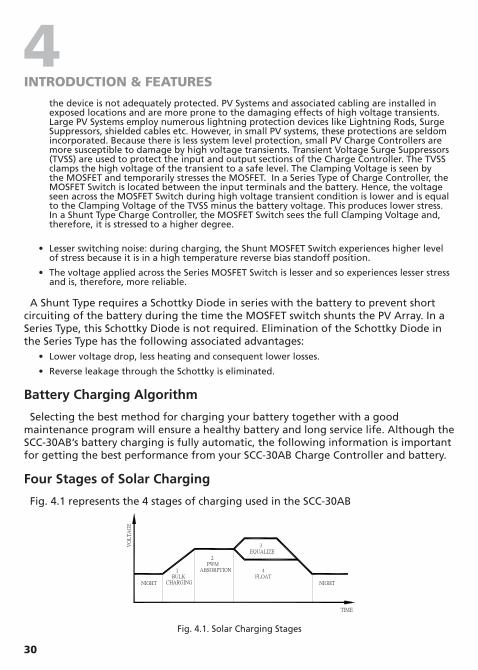
Fig. 4.1 represents the 4 stages of charging used in the SCC-30AB
VO
LT
AG
E
TIME
NIGHTNIGHT
4FLOAT
3EQUALIZE
2 PWMABSORPTION 1
BULKCHARGING
Fig. 4.1. Solar Charging Stages
31
4INTRODUCTION & FEATURES
1. Bulk Charging: In this stage, the battery will accept all the current provided by the solar array. The value of this current will be equal to the Short Circuit Current Isc of the solar array.
2. PWM Absorption: When the battery reaches the Absorption Voltage, the PWM begins to hold the voltage constant. This is to avoid over-heating and over-gassing the battery. The current will taper off to safe levels as the battery becomes more fully charged.
3. Equalization: Many batteries benefit from a periodic boost charge to stir the electrolyte, equalize the cell voltages, and complete the chemical reactions (See additional details on Equalization given below).
4. Float: When a battery becomes fully charged, dropping down to the float stage will provide a very low rate of maintenance charging while reducing the heating and gassing of a fully charged battery. When the battery is fully recharged, there can be no more chemical reactions and all the charging current is turned into heat and gassing. The purpose of float is to protect the battery from long-term overcharge. From the PWM absorption stage, charging is dropped to the float voltage. This is typically 13.4V for a 12V battery.
Equalization
Caution!
• Equalization is carried out only for non-sealed / vented / flooded / well cell lead acid batteries.
• Do not equalize sealed / VRLA type of AGM / Gel cell batteries.
• Top up the electrolyte with distilled water after completion of equalization.
Routine equalization cycles are often vital to the performance and life of a battery — particularly in a solar system. During battery discharge, sulfuric acid is consumed and soft lead sulfate crystals form on the plates. If the battery remains in a partially discharged condition, the soft crystals will turn into hard crystals over time. This process, called “lead sulfation,” causes the crystals to become harder over time and more difficult to convert back to soft active materials.
Sulfation from chronic undercharging of the battery is the leading cause of battery failures in solar systems. In addition to reducing the battery capacity, sulfate build-up is the most common cause of buckling plates and cracked grids. Deep cycle batteries are particularly susceptible to lead sulfation.

32
4INTRODUCTION & FEATURES
Normal charging of the battery can convert the sulfate back to the soft active material if the battery is fully recharged. However, a solar battery is seldom completely recharged, so the soft lead sulfate crystals harden over a period of time. Only a long controlled overcharge, or equalization, at a higher voltage can reverse the hardening sulfate crystals.
In addition to slowing or preventing lead sulfation, there are also other benefits of equalization of the solar system battery. These include:
Balance the individual cell voltages
Over time, individual cell voltages can drift apart due to slight differences in the cells. For example, in a 12 cell (24V) battery, one cell may be less efficient in recharging to a final Absorption Voltage of 28.8 volts (2.4 V/cell). Over time, that cell only reaches 1.85 volts, while the other 11 cells charge to 2.45 volts per cell. The overall Absorption Voltage is 28.8V, but the individual cells are higher or lower due to cell drift. Equalization cycles help to bring all the cells to the same voltage.
Mix the electrolyte
In flooded batteries, especially tall cells, the heavier acid will fall to the bottom of the cell over time. This stratification of the electrolyte causes loss of capacity and corrosion of the lower portion of the plates. Gassing of the electrolyte from a controlled overcharging (equalization) will stir and remix the acid into the battery electrolyte.
NOTE: Excessive overcharging and gassing too vigorously can damage the battery plates and cause shedding of active material from the plates. An equalization that is too high or for too long can be damaging. Review the requirements for the particular battery being used in your system.
When to Equalize
The ideal frequency of equalizations depends on the battery type (Lead Calcium, Lead-Antimony, etc.), the depth of discharging, battery age, temperature, and other factors.
One very broad guide is to equalize flooded batteries every 1 to 3 months or every 5 to 10 deep discharges. Some batteries, such as the L-16 group, will need more frequent equalizations.
The difference between the highest cell and lowest cell in a battery can also indicate the need for equalization. Either the specific gravity or the cell voltage can be measured. The battery manufacturer can recommend the specific gravity or voltage values for your particular battery. Normally, if the cell voltage differential is > 0.2 V, equalization may be necessary.

33
5CONSTRUCTION, LAYOUT & CONTROLS
General
SCC-30AB is designed for flush mounting on a wall / panel. The controls and indications are built on the Front Panel face plate that has 4 countersunk holes for flush mounting (Fig. 5.1). All the electronics, DIP switches for settings, terminal strip for connections for the PV Array and the Battery and terminal for the optional Battery Temperature Sensor (BTS) are mounted on a PCB that is in turn mounted at the back of the face plate (Fig. 5.2). For flush mounting on the wall / panel, a suitable cutout is required to be made in the wall / panel to accommodate the PCB at the back of the unit. As the components at the back of the unit will be hidden and protected behind the wall / panel, the components at the back of the unit are exposed and do not have a protective cover. PLEASE HANDLE THE UNIT CAREFULLy TO PREVENT ANy DAMAGE TO THE EXPOSED COMPONENTS AT THE BACK OF THE UNIT.NOTE: As the unit will be connected to 12 V / 24 V Nominal Solar Array / battery system, there is no likelihood of electrical shock.
Fig. 5.1. Front Panel of SCC-30AB
Fig. 5.2. Back view of SCC-30AB

34
5CONSTRUCTION, LAYOUT & CONTROLS
Controls & Indications
The description and the functions of the controls and indications are given below:
Front Panel
Charge Status LED Indications
LED STATE INDICATION
Blinking GreenCharging is in the state of Bulk or Absorption depending upon the number of blinks as follows:
For 12 V Battery For 24 V Battery
- 1 Green Blink> 0.75 V below Absorption Voltage setting
> 1.5 V below Absorption voltage setting
- 2 Green Blinks0.75 V below Absorption Voltage setting
1.5 V below Absorption Voltage setting
- 3 Green Blinks0.5 V below Absorption Voltage setting
1.0 V below Absorption Voltage setting
- 4 Green Blinks0.25 V below Absorption Voltage setting
0.5 V below Absorption Voltage setting
- 5 Green Blinks At Absorption Voltage setting At Absorption Voltage setting
Solid Green Charging is in the state of Float
Solid Orange Charging is in the state of Equalization
Solid RedCharging is in the state of fault: Over current or low DC voltage or operating temp below 0°C (32°F)
Blinking Red Charging is in the state of fault: Over Temperature
Push Buttons
BUTTONS ACTION
Display Reset Amp-Hours
Push to change the display as in Fig. 5.3.Push and hold to reset Amp-Hours.
Equalization Start/Stop
When DIP Switch 5 is set at OFF, hold Restart/Stop Equalization for 5 sec to manually start equalization. Press it for 2 sec to stop equalization.
35
5CONSTRUCTION, LAYOUT & CONTROLS
LCD Display
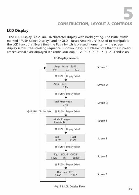
The LCD Display is a 2 Line, 16 character display with backlighting. The Push Switch marked “PUSH Select Display” and “HOLD – Reset Amp Hours” is used to manipulate the LCD functions. Every time the Push Switch is pressed momentarily, the screen display scrolls. The scrolling sequence is shown in Fig. 5.3. Please note that the 7 screens are sequential & are displayed in a continuous loop: 1 - 2 - 3 - 4 - 5 - 6 - 7 - 1 - 2 - 3 and so on.
Amp Watts BatV0.0 0.0 12.0
Amp-Hours0 Ah
Total Amp-Hours0 Ah
Mode: ChargerState: Bulk
Bulk Float14.0V 13.4V
EQU EQU-T CYCLE14.2V 1hr 28day
Heatsink BTS25oC 25oC
PUSH: Display Select
PUSH: Display Select
PUSH: Display Select
PUSH: Display Select
PUSH: Display Select
PUSH: Display Select
PUSH: Display Select
LED Display Screens
Screen 1
Screen 2
Screen 3
Screen 4
Screen 5
Screen 6
Screen 7
Fig. 5.3. LCD Display Flow

36
5CONSTRUCTION, LAYOUT & CONTROLS
The details of information provided in the LCD screens are given below:
Screen 1 • Shows the solar array current / charging current in Amperes (Amp), battery voltage in V
(BatV) and the power delivered by the solar array / fed to the batteries in Watts (Watts). The value of Watts = the charging current in Amperes (Amp) x Battery Voltage in V (BatV).
Screen 2 • It is a resettable counter that displays the Ampere Hours (Amp-Hours) of energy (in Ah)
delivered by the solar panel into the batteries with effect from the time the solar panel has been connected or with effect from a desired starting / reference point after the counter is set to 0. The counter can be set to zero with the help of the Push Button marked “Reset Amp-Hours” (Push and hold the Push Button till the counter resets to 0). For example, due to its 75% to 85 % efficiency, a lead acid battery requires up to around 130% of Amp-Hour energy as compared to its rated Amp-Hour capacity to recharge fully. Hence, during start of recharging of say a fully discharged 100 AH battery, the Amp-Hours counter can be set to 0. As 130 Amp-Hour of energy will be required to re-charge a fully discharged 100 AH battery, a healthy battery is likely to be fully recharged when the Amp-Hour counter approaches 130 Amp-Hours.
Screen 3 • Counts the total running Ampere Hours (Amp-Hours) of energy (in Ah) delivered by the
solar panel into the batteries. This will only reset if the battery connection is removed.
Screen 4 • Shows the charging Mode in progress: Bulk or Absorption or Equalization or Float.
Screen 5 • Shows the Bulk (Absorption) and Float voltages that have been set for the desired battery
type / charging algorithm corresponding to one of the 8 options that can be selected with the help of DIP Switches 2, 3, 4 (See Chapter 6, Table 6.1).
Screen 6 • Displays the Equalization Voltage (EQU, in Volts), Equalization Time (EQU-T, in Hours) and
Equalization Cycle (CYCLE, in days). These parameters are automatically set once a particular battery type / charging algorithm corresponding to one of the 8 options has been selected using DIP Switches 2,3,4 (See Chapter 6, Table 6.1).
Screen 7 • Displays the heat sink temperature (Heatsink) in °C (the metal plate of the front panel acts as
the heat sink). It also displays the temperature of the battery in °C when the optional Battery Temperature Sensor (BTS) Model No. DC-BTS-A-C is used.
NOTE: The battery temperature can not be displayed below 0° C. If the battery temperature falls below 0° C, the display will read “- - - ° C”.
37
5CONSTRUCTION, LAYOUT & CONTROLS
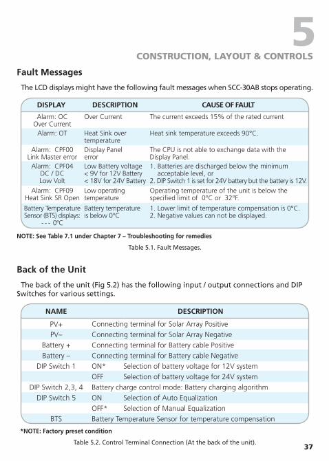
Fault Messages
The LCD displays might have the following fault messages when SCC-30AB stops operating.
DISPLAy DESCRIPTION CAUSE OF FAULT
Alarm: OC Over Current
Over Current The current exceeds 15% of the rated current
Alarm: OT Heat Sink over temperature
Heat sink temperature exceeds 90°C.
Alarm: CPF00 Link Master error
Display Panel error
The CPU is not able to exchange data with the Display Panel.
Alarm: CPF04DC / DC Low Volt
Low Battery voltage < 9V for 12V Battery < 18V for 24V Battery
1. Batteries are discharged below the minimum acceptable level, or 2. DIP Switch 1 is set for 24V battery but the battery is 12V.
Alarm: CPF09Heat Sink SR Open
Low operatingtemperature
Operating temperature of the unit is below the specified limit of 0°C or 32°F.
Battery Temperature Sensor (BTS) displays:
- - - 0°C
Battery temperatureis below 0°C
1. Lower limit of temperature compensation is 0°C. 2. Negative values can not be displayed.
NOTE: See Table 7.1 under Chapter 7 – Troubleshooting for remedies
Table 5.1. Fault Messages.
Back of the Unit
The back of the unit (Fig 5.2) has the following input / output connections and DIP Switches for various settings.
NAME DESCRIPTION
PV+ Connecting terminal for Solar Array PositivePV– Connecting terminal for Solar Array Negative
Battery + Connecting terminal for Battery cable Positive Battery – Connecting terminal for Battery cable Negative
DIP Switch 1 ON* Selection of battery voltage for 12V systemOFF Selection of battery voltage for 24V system
DIP Switch 2,3, 4 Battery charge control mode: Battery charging algorithmDIP Switch 5 ON Selection of Auto Equalization
OFF* Selection of Manual EqualizationBTS Battery Temperature Sensor for temperature compensation
*NOTE: Factory preset condition
Table 5.2. Control Terminal Connection (At the back of the unit).
38
6INSTALLATION & OPERATION
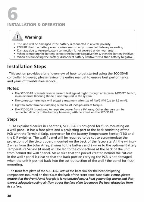
Warning!
• This unit will be damaged if the battery is connected in reverse polarity. • ENSURE that the battery + and - wires are correctly connected before proceeding. • Damage due to reverse battery connection is not covered under warranty! • When connecting the battery, connect the battery Negative first & then the battery Positive. • When disconnecting the battery, disconnect battery Positive first & then battery Negative.
Installation StepsThis section provides a brief overview of how to get started using the SCC-30AB
controller. However, please review the entire manual to ensure best performance and years of trouble-free service.
Notes: • The SCC-30AB prevents reverse current leakage at night through an internal MOSFET Switch,
so an external Blocking Diode is not required in the system.
• The connector terminals will accept a maximum wire size of AWG #10 (up to 5.2 mm2).
• Tighten each terminal clamping screw to 20 inch-pounds of torque.
• The SCC-30AB is designed to regulate power from a PV array. Other chargers can be connected directly to the battery, however, with no effect on the SCC-30AB.
Steps
1. As explained earlier in Chapter 4, SCC-30AB is designed for flush mounting on a wall panel. It has a face plate and a projecting part at the back consisting of the PCB with the Terminal Strip, connector for the Battery Temperature Sensor (BTS) and the DIP switches. The wall / panel will be required to be cut to accommodate the projections of the circuit board mounted on the back of the faceplate. All the wiring – 2 wires from the Solar Array, 2 wires to the battery and 2 wires to the optional Battery Temperature Sensor (if used) will be led to the connections at the back of the unit from behind the wall / panel. Make sure that the pocket created behind the cut-out in the wall / panel is clear so that the back portion carrying the PCB is not damaged when the unit is pushed back into the cut-out section of the wall / the panel for flush mounting.
The front face plate of the SCC-30AB acts as the heat sink for the heat dissipating components mounted on the PCB at the back of the Front Panel face plate. Hence, please ensure that the Front Panel face plate is not located near a heat generating source and that there is adequate cooling air flow across the face plate to remove the heat dissipated from its surface.

39
6INSTALLATION & OPERATION
A drawing for making the cutout in the wall / panel is given at Fig 6.1 (not to scale).
A full scale template is also included in the gift box to help direct marking the area to be cut out. 4 screws have been provided to fix the unit to the wall / panel.
1“ / 25 mm
1“ /
25 m
m
1“ /
25 m
m
1“ / 25 mm
1“ /
25 m
m
1“ / 25 mm 1“ / 25 mm
1“ /
25 m
m
1/4“ / 6 mm
1/4“
/ 6
mm
1/4“
/ 6
mm
1/4“ / 6 mm
7.5” / 190 mm
4 1/
4” /
108
mm
7” / 178 mm3
3/4”
/ 96
mm
- Cut the wall / panel along the dotted line with a jig saw.- This will create a pocket in the wall / panel for ush mounting of Charge Controller SCC-30AB.
Outline of the front panel
Fig. 6.1. Drawing for making the cut-out in the wall / panel
2. Make sure the PV currents will not exceed the ratings of the SCC-30AB.
3. The connections to the SCC-30AB terminals are shown in the drawing at Fig. 5.2. A barrier type of Terminal Strip has been provided for connecting the PV array and the battery. M-4 screws with clamping washers are used to make the connection. A flat or a #2 Philips head screw driver may be used to tighten these screws. Tighten each terminal clamping screw to 20 inch-pounds of torque. The distance between the barriers is 9 mm and a standard Spade Type of terminal lug meant for # 8 Stud and AWG #10 – AWG #12 wire may be used at the end of the wires to be connected to these terminals. 4 such terminal lugs are provided with the unit for ease of installation.
4. Set the DIP Switch 1 for the voltage system, set the DIP Switch 2, 3, 4 for battery charging algorithm (see Table 6.1).
5. Connect the BATTERY first. Be careful that bare wires do not touch the metal case of the controller. Connect battery Negative first and then the battery Positive.
• The BATTERY must be connected before the Solar Panel (Module)/Array to properly start the microcontroller, activate protections & guide installation.
• A battery below 9 V for 12 V battery or 18 V for 24 V battery may not start the microcontroller properly. Make sure the battery is charged before installing the system.
40
6INSTALLATION & OPERATION
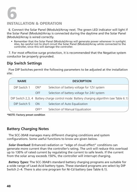
6. Connect the Solar Panel (Module)/Array next. The green LED indicator will light if the Solar Panel (Module)/Array is connected during the daytime and the Solar Panel (Module)/Array is wired correctly.
• Remember that the Solar Panel (Module)/Array will generate power whenever in sunlight. Also, be careful not to short circuit the Solar Panel (Module)/Array while connected to the controller, since this will damage the controller.
7. For most effective surge protection, it is recommended that the Negative system conductor be properly grounded.
Dip Switch Settings
Five DIP Switches permit the following parameters to be adjusted at the installation site:
NAME DESCRIPTION
DIP Switch 1 ON* Selection of battery voltage for 12V system
OFF Selection of battery voltage for 24V system
DIP Switch 2,3, 4 Battery charge control mode: Battery charging algorithm (see Table 6.1)
DIP Switch 5 ON Selection of Auto Equalization
OFF* Selection of Manual Equalization
*NOTE: Factory preset condition
Battery Charging Notes
The SCC-30AB manages many different charging conditions and system configurations. Some useful functions to know are given below.
Solar Overload: Enhanced radiation or “edge of cloud effect” conditions can generate more current than the controller’s rating. The unit will reduce this overload up to 130% of rated current by regulating the current to safe levels. If the current from the solar array exceeds 150%, the controller will interrupt charging.
Battery Types: The SCC-30AB’s standard battery charging programs are suitable for a wide range of Lead-Acid battery types. These standard programs are select by DIP Switch 2~4. There is also one program for Ni-Cd battery (see Table 6.1).

41
6INSTALLATION & OPERATION
Standard Battery Charging Programs
The SCC-30AB provides 8 standard battery charging algorithms (programs) that are selected with DIP Switches 2, 3, 4. These standard algorithms are suitable for Lead-Acid batteries ranging from sealed (Gel, AGM, maintenance free) to flooded to L-16 cells and Ni-Cd etc.
Table 6.1 below summarizes the major parameters of the standard charging algorithms. Note that all the voltages are for 12V systems. For 24 V system, multiply the voltages by 2.
• Consult the battery manufacturer / battery specifications & select the appropriate Algorithm. • The unit is preset for Battery Type 1 (off-off-off) for a sealed / VRLA battery. • For a generic non-sealed / vented / flooded / well cell Lead Acid battery, choose Battery Type 4.
Note: 1. All voltage values are at 25 ºC (77 ºF). 2. All the voltages given in the Table are for 12V Battery System. For 24V Battery Systems multiply the voltage values by 2.
A B C D E F
DIP Switches (2-3-4)
Battery Type
PWM Absorption
Voltage
Float Voltage
Equalize Voltage
Equalize Time
(hours)
EqualizeInterval (days)
Off-Off-Off(Factory Preset) 1 – Sealed 14.0 13.4 None - -
Off-Off-On 2 – Sealed 14.1 13.4 14.2 1 28
Off-On-Off 3 - Sealed 14.3 13.4 14.4 2 28
Off-On-On 4 - Flooded 14.4 13.4 15.1 3 28
On-Off-Off 5 - Flooded 14.6 13.4 15.3 3 28
On-Off-On 6 - Flooded 14.8 13.4 15.3 3 28
On-On-Off 7 - L-16 15.0 13.4 15.3 3 14
On-On-On 8 - Ni-Cd 16.0 14.5 None - -
Table 6.1. Standard Battery Charging Programs
A. Battery Type These are generic Lead-Acid – wet cell (Lead Antimony, Lead Calcium), sealed AGM, sealed Gel Cell and Ni-Cd battery types.
B. Voltage This is the PWM Absorption Stage with constant voltage charging. The “PWM Absorption voltage” is the maximum battery voltage that will be held constant. As the battery becomes more charged, the charging current tapers off until the battery is fully charged.
C. Float Voltage When the battery is fully charged, the charging voltage will be reduced to 13.4 volts for all battery types. It will be 14.5V for Ni-Cd.
D. Equalization Voltage During an equalization cycle, the charging voltage will be held constant at this voltage.
42
6INSTALLATION & OPERATION
E. Equalization Time The charging at the selected equalization voltage will continue for this number of hours.
F. Equalization Interval Equalizations are typically done once a month. Most of the cycles are 28 days so the equalization will begin on the same day of the month. Each new cycle will be reset as the equalization starts so that a setting day period will be maintained.
Equalization Procedure
Standard Equalization Programs
Both automatic and manual equalizations can be performed using the standard charging programs.
Manual Equalization
The SCC-30AB is shipped with the DIP Switch 5 set for manual equalization only. This is to avoid an unexpected or unwanted automatic equalization. In the Manual Mode, the push button marked “Equalization” is used to both start and stop a manual equalization. Hold the push button down for 5 seconds to start and 3 seconds to stop an equalization (depending on whether an equalization is in progress or not).
There are no limits to how many times the push button can be used to start and stop equalizations. Equalizations will be terminated automatically as per the charging program selected if the push button is not used to manually stop the equalization.
Automatic Equalization
If the equalization DIP Switch 5 is moved to the ON position, the equalizations will begin automatically as per the charging program selected. Other than starting, the automatic and manual equalizations are the same and follow the standard charging program selected. The push button can be used to start and stop equalizations in both the manual and automatic mode.
Typical Equalization
The automatic equalizations will occur at the selected charging program from DIP Switch 2~4. When equalization begins (Auto or Manual), the battery charging voltage increases up to the Equalization Voltage Veq. The battery will remain at Veq for the time specified in the selected charging program.
The equalization process will continue until the voltage has been held above the bulk (Absorption) setting for a cumulative period of one, two or three hours. A second manual equalization cycle can be started with the push button, if needed.
If the equalization cannot be completed in one day, it will continue the next day or days until finished. After equalization is completed, charging will return to PWM Absorption.
43
6INSTALLATION & OPERATION
Temperature Compensated Battery Charging
An optional Battery Temperature Sensor (BTS), Model No. DC-BTS-A-C is available for temperature compensated battery charging.
The BTS consists of a temperature sensing probe that is installed on the + battery post. The temperature of the battery post reflects the approximate temperature of the electrolyte. A pair of 10 metres wires (marked + & -) connect the temperature sensing probe to the 2 terminals marked BTS at the back of the unit (Fig. 5.2).
As the battery gets warmer, the gassing increases. As the battery gets colder, it becomes more resistant to charging. Depending on how much the battery electrolyte temperature varies, it is important to adjust the charging for temperature changes.
Various voltage set points given in the specifications are indicated at a reference temperature of 25 ºC / 77 ºF.
It is recommended that the optional Battery Temperature Sensor (BTS) Model No. DC-BTS-A-C may be used if the battery electrolyte temperature (measured at the + terminal stud) varies more than 5 ºC to 10 ºC (9 ºF to 18 ºF) from the reference temperature of 25 ºC (77 ºF).
There are three battery charging parameters that are affected by temperature:
PWM Absorption
This is the most important part of charging that is affected by temperature because the charging may go into PWM absorption almost every day. If the battery temperature is colder, the charging will begin to regulate too soon and the battery may not be recharged with a limited solar resource. If the battery temperature rises, the battery may heat and gas too much.
Equalization
A colder battery will lose part of the benefit of the equalization. A warmer battery may heat and gas too much.
Float
Float is less affected by temperature changes, but it may also undercharge or gas too much depending on how much the temperature changes.
The Battery Temperature Sensor (BTS) corrects the three charging set points noted above by the following values (reference temperature is 25 ºC / 77 ºF):
• 12 volt battery: –0.030 volts per °C (–0.017 volts per °F).
• 24 volt battery: –0.060 volts per °C (–0.033 volts per °F).
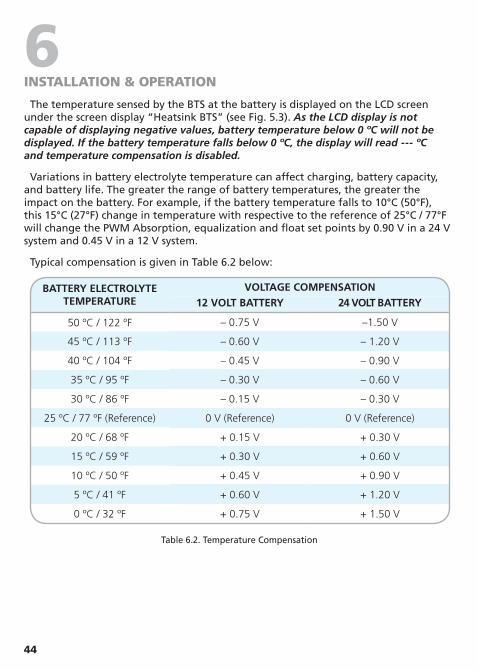
44
6INSTALLATION & OPERATION
The temperature sensed by the BTS at the battery is displayed on the LCD screen under the screen display “Heatsink BTS” (see Fig. 5.3). As the LCD display is not capable of displaying negative values, battery temperature below 0 ºC will not be displayed. If the battery temperature falls below 0 ºC, the display will read --- ºC and temperature compensation is disabled.
Variations in battery electrolyte temperature can affect charging, battery capacity, and battery life. The greater the range of battery temperatures, the greater the impact on the battery. For example, if the battery temperature falls to 10°C (50°F), this 15°C (27°F) change in temperature with respective to the reference of 25°C / 77°F will change the PWM Absorption, equalization and float set points by 0.90 V in a 24 V system and 0.45 V in a 12 V system.
Typical compensation is given in Table 6.2 below:
BATTERy ELECTROLyTE TEMPERATURE
VOLTAGE COMPENSATION12 VOLT BATTERy 24 VOLT BATTERy
50 ºC / 122 ºF – 0.75 V –1.50 V
45 ºC / 113 ºF – 0.60 V – 1.20 V
40 ºC / 104 ºF – 0.45 V – 0.90 V
35 ºC / 95 ºF – 0.30 V – 0.60 V
30 ºC / 86 ºF – 0.15 V – 0.30 V
25 ºC / 77 ºF (Reference) 0 V (Reference) 0 V (Reference)
20 ºC / 68 ºF + 0.15 V + 0.30 V
15 ºC / 59 ºF + 0.30 V + 0.60 V
10 ºC / 50 ºF + 0.45 V + 0.90 V
5 ºC / 41 ºF + 0.60 V + 1.20 V
0 ºC / 32 ºF + 0.75 V + 1.50 V
Table 6.2. Temperature Compensation
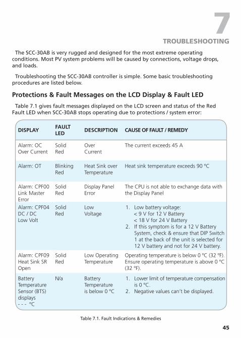
45
7TROUBLEShOOTING
The SCC-30AB is very rugged and designed for the most extreme operating
conditions. Most PV system problems will be caused by connections, voltage drops, and loads.
Troubleshooting the SCC-30AB controller is simple. Some basic troubleshooting procedures are listed below.
Protections & Fault Messages on the LCD Display & Fault LED
Table 7.1 gives fault messages displayed on the LCD screen and status of the Red Fault LED when SCC-30AB stops operating due to protections / system error:
DISPLAyFAULTLED
DESCRIPTION CAUSE OF FAULT / REMEDy
Alarm: OC Over Current
Solid Red
Over Current
The current exceeds 45 A
Alarm: OT Blinking Red
Heat Sink over Temperature
Heat sink temperature exceeds 90 ºC
Alarm: CPF00 Link Master Error
Solid Red
Display Panel Error
The CPU is not able to exchange data with the Display Panel
Alarm: CPF04 DC / DC Low Volt
Solid Red
Low Voltage
1. Low battery voltage:< 9 V for 12 V Battery< 18 V for 24 V Battery
2. If this symptom is for a 12 V Battery System, check & ensure that DIP Switch 1 at the back of the unit is selected for 12 V battery and not for 24 V battery.
Alarm: CPF09 Heat Sink SR Open
Solid Red
Low Operating Temperature
Operating temperature is below 0 ºC (32 ºF). Ensure operating temperature is above 0 ºC (32 ºF).
Battery Temperature Sensor (BTS) displays - - - ºC
N/a Battery Temperatureis below 0 ºC
1. Lower limit of temperature compensation is 0 ºC.
2. Negative values can’t be displayed.
Table 7.1. Fault Indications & Remedies
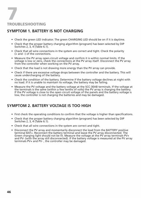
46
7TROUBLEShOOTING
SyMPTOM 1. BATTERy IS NOT CHARGING
• Check the green LED indicator. The green CHARGING LED should be on if it is daytime.
• Check that the proper battery charging algorithm (program) has been selected by DIP Switches 2, 3, 4 (Table 6.1).
• Check that all wire connections in the system are correct and tight. Check the polarity (+ and –) of the connections.
• Measure the PV array open-circuit voltage and confirm it is within normal limits. If the voltage is low or zero, check the connections at the PV array itself. Disconnect the PV array from the controller when working on the PV array.
• Check that the load is not drawing more energy than the PV array can provide.
• Check if there are excessive voltage drops between the controller and the battery. This will cause undercharging of the battery.
• Check the condition of the battery. Determine if the battery voltage declines at night with no load. If it is unable to maintain its voltage, the battery may be failing.
• Measure the PV voltage and the battery voltage at the SCC-30AB terminals. If the voltage at the terminals is the same (within a few tenths of volts) the PV array is charging the battery. If the PV voltage is close to the open circuit voltage of the panels and the battery voltage is low, the controller is not charging the batteries and may be damaged.
SyMPTOM 2. BATTERy VOLTAGE IS TOO HIGH
• First check the operating conditions to confirm that the voltage is higher than specifications.
• Check that the proper battery charging algorithm (program) has been selected by DIP Switches 2, 3, 4 (Table 6.1).
• Check that all wire connections in the system are correct and tight.
• Disconnect the PV array and momentarily disconnect the lead from the BATTERY positive terminal BAT+. Reconnect the battery terminal and leave the PV array disconnected. The Green charging light should not be lit. Measure the voltage at the PV array terminals PV+ and PV- (with the array still disconnected). If the battery voltage is measured at the PV array terminals PV+ and PV- , the controller may be damaged.

47
8SPECIFICATIONS
CHARACTERISTICS SPECIFICATIONS
SySTEM
Nominal system voltage 12 VDC or 24 VDC (Selected by DIP Switch)
Current rating 30 A
Set point accuracy + / - 50 mV
Minimum voltage to start the micro-controller, activate protections and guide operation
9 VDC for 12 V Battery System18 VDC for 24 V Battery System
Total self consumption current 50 mA
INPUT SIDE (Solar panel / array)
Maximum open circuit voltage Voc of the solar panel/array 50 VDC
Maximum operating voltage of the solar panel/array 34 VDC
Maximum short circuit current Isc of the solar panel/array 30 A
BATTERy CHARGING
Charging algorithm PWM
Charging stages Bulk, Absorption, Float, Equalize (Selectable)
Battery Temperature CompensationWith optional Battery Temperature Sensor (BTS), Model DC-BTS-A-C supplied with 10 metres of wire
Voltage coefficient of Temperature change when using optional Battery Temperature Sensor (BTS ) - Model DC-BTS-A-C
- 5mV / ºC / cell (25 ºC reference)- 10mV / ºC / cell (25 ºC reference)
Temperature compensation range 0 ºC to +50 ºC
PROTECTIONS
High temp shutdown (Temp of the face plate that is used as a heat sink)
90 ºC disconnect solar panel/array70 ºC re-connect solar panel/array
Over current (overload) shut down 45 A
DISPLAy
Backlit LCD 2 lines X 16 characters, alpha numeric
LED 1 LED for status display
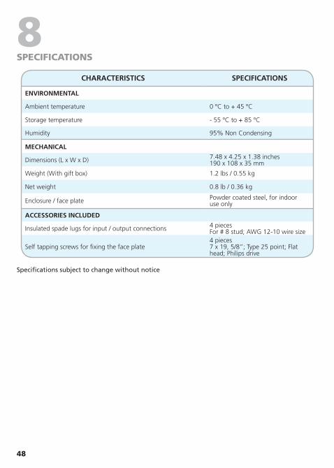
48
8SPECIFICATIONS
CHARACTERISTICS SPECIFICATIONS
ENVIRONMENTAL
Ambient temperature 0 ºC to + 45 ºC
Storage temperature - 55 ºC to + 85 ºC
Humidity 95% Non Condensing
MECHANICAL
Dimensions (L x W x D) 7.48 x 4.25 x 1.38 inches190 x 108 x 35 mm
Weight (With gift box) 1.2 lbs / 0.55 kg
Net weight 0.8 lb / 0.36 kg
Enclosure / face plate Powder coated steel, for indooruse only
ACCESSORIES INCLUDED
Insulated spade lugs for input / output connections 4 pieces For # 8 stud; AWG 12-10 wire size
Self tapping screws for fixing the face plate4 pieces 7 x 19, 5/8”; Type 25 point; Flat head; Philips drive
Specifications subject to change without notice

49
9wARRANTY
5 yEAR Limited Warranty
SCC-30AB manufactured by Samlex America, Inc. (the “Warrantor”) is warranted to be free from defects in workmanship and materials under normal use and service. This warranty is in effect for 5 years from the date of purchase by the user (the “Purchaser”).
For a warranty claim, the Purchaser should contact the place of purchase to obtain a Return Authorization Number.
The defective part or unit should be returned at the Purchaser’s expense to the authorized location. A written statement describing the nature of the defect, the date of purchase, the place of purchase, and the Purchaser’s name, address and telephone number should also be included.
If upon the Warrantor’s examination, the defect proves to be the result of defective material or workmanship, the equipment will be repaired or replaced at the Warrantor’s option without charge, and returned to the Purchaser at the Warrantor’s expense.
No refund of the purchase price will be granted to the Purchaser, unless the Warrantor is unable to remedy the defect after having a reasonable number of opportunities to do so.
Warranty service shall be performed only by the Warrantor. Any attempt to remedy the defect by anyone other than the Warrantor shall render this warranty void.
There shall be no warranty for defects or damages caused by faulty installation or hook-up, abuse or misuse of the equipment including exposure to excessive heat, salt or fresh water spray, or water immersion.
No other express warranty is hereby given and there are no warranties which extend beyond those described herein. This warranty is expressly in lieu of any other expressed or implied warranties, including any implied warranty of merchantability, fitness for the ordinary purposes for which such goods are used, or fitness for a particular purpose, or any other obligations on the part of the Warrantor or its employees and representatives.
There shall be no responsibility or liability whatsoever on the part of the Warrantor or its employees and representatives for injury to any persons, or damage to person or persons, or damage to property, or loss of income or profit, or any other consequential or resulting damage which may be claimed to have been incurred through the use or sale of the equipment, including any possible failure of malfunction of the equipment, or part thereof.
The Warrantor assumes no liability for incidental or consequential damages of any kind.
Samlex America Inc. (the “Warrantor”)110-17 Fawcett RoadCoquitlam BC, V3K 6V2 Canada(604) 525-3836

50
NOTES

51
NOTES

110-17 Fawcett RdCoquitlam, B.C.Canada V3K 6V2
T: 604 525 3836F: 604 525 5221
TF: 1 800 561 5885
e-mail: [email protected]: www.samlexamerica.com
SCC-30AB_Charge_Controller_Manual_Feb2011
![Improved Quantum Sensing with a Single Solid-State Spin ...walsworth.physics.harvard.edu/publications/2019_Jaskula_PRApplied.pdfB. Spin-to-charge conversion SCC read-out [12] transfers](https://img.pdfslide.us/doc/110x75/5eb7b29628a4d83e9c23aa9b/improved-quantum-sensing-with-a-single-solid-state-spin-b-spin-to-charge-conversion.jpg)