Embed Size (px)
Citation preview
DOI : 10.23883/IJRTER.2017.3452.845G6 45
AN ANALYTICAL APPROACH TO HARMONIC ANALYSIS AND
CONTROLLER DESIGN OF STATCOM
ARAVIND RAMLAKHAN BENKAR1, K.KIRAN
2
1M.Tech Scholar,
2Assistant Professor
1,2Dept of EEE, Narayana Engineering And Technical Campus, Jafferguda, Batasingaram,
Hayathnagar, Telangana, India.
Abstract: - The study of shunt connected FACTS devices is a connected field with the problem of
reactive power compensation and better mitigation of transmission related problems in today’s
world. In this paper we study the shunt operation of FACTS controller, the STATCOM, and how it
helps in the better utilization of a network operating under normal conditions. First we carry out a
literature review of many papers related to FACTS and STATCOM, along with reactive power
control. Then we look at the various devices being used for both series and shunt compensation. The
study of STATCOM and its principles of operation and control, including phase angle control and
PWM techniques, are carried out. We also delve into the load flow equations which are necessary for
any power system solution and carry out a comprehensive study of the Newton Raphson method of
load flow. Apart from this, we also carry out a study of the transient stability of power systems, and
how it is useful in determining the behavior of the system under a fault. As an example, a six bus
system is studied using the load flow equations and solving them. First this is done without the
STATCOM and then the STATCOM is implemented and the characteristics of the rotor angle graph
along with faults at various buses are seen. In this thesis, it is tried to show the application of
STATCOM to a bus system and its effect on the voltage and angle of the buses. Next the graphs
depicting the implemented STATCOM bus are analyzed and it is shown that the plots of the rotor
angles show a changed characteristic under the influence of the STATCOM.
Keywords: Controller design, DC-link voltage, FACTS- statcom, Power factor.
I. INTRODUCTION
Power Generation and Transmission is a complex process, requiring the working of many
components of the power system in tandem to maximize the output. One of the main components to
form a major part is the reactive power in the system. It is required to maintain the voltage to deliver
the active power through the lines. Loads like motor loads and other loads require reactive power
for their operation. To improve the performance of ac power systems, we need to manage this
reactive power in an efficient way and this is known as reactive power compensation. There are two
aspects to the problem of reactive power compensation: load compensation and voltage support.
Load compensation consists of improvement in power factor, balancing of real power drawn from
the supply, better voltage regulation, etc. of large fluctuating loads.
Voltage support consists of reduction of voltage fluctuation at a given terminal of the transmission
line. Two types of compensation can be used: series and shunt compensation. These modify the
parameters of the system to give enhanced VAR compensation. In recent years, static VAR
compensators like the STATCOM have been developed. These quite satisfactorily do the job of
absorbing or generating reactive power with a faster time response and come under Flexible AC
Transmission Systems (FACTS). This allows an increase in transfer of apparent power through a
transmission line, and much better stability by the adjustment of parameters that govern the power
system i.e. current, voltage, phase angle, frequency and impedance. The use of facts devices in a
International Journal of Recent Trends in Engineering & Research (IJRTER)
Volume 03, Issue 10; October - 2017 [ISSN: 2455-1457]
@IJRTER-2017, All Rights Reserved 46
power system can potentially overcome limitations of the present mechanically controlled
transmission systems. By facilitating bulk power transfers, these interconnected networks help
minimize the need to enlarge power plants and enable neighboring utilities and regions to exchange
power. The stature of FACTS devices within the bulk power system will continually increase as the
industry moves toward a more competitive posture in which power is bought and sold as a
commodity. As power wheeling becomes increasingly prevalent, power electronic devices will be
utilized more frequently to insure system reliability and stability and to maximum power
transmission along various transmission corridors.
The static synchronous compensator, or Statcom, is a shunt connected FACTS device. It
generates a balanced set of three phase sinusoidal voltages at the fundamental frequency, with
rapidly controllable amplitude and phase angle. This type of controller can be implemented using
various topologies. A Static Compensator (Statcom) is a device that can provide reactive support to a
bus. It consists of voltage sourced converters connected to an energy storage device on one side and
to the power system on the other.
1.1 Objectives:
The study of shunt connected FACTS devices is a connected field with the problem of reactive
power compensation and better mitigation of transmission related problems in today’s world. In this
thesis deals the study of the shunt operation of FACTS controller, the STATCOM, and how it helps
in the better utilization of a network operating under normal conditions. The main objectives of
studying the STATCOM are described below.
1. A brief study about reactive power compensation using STATCOM.
2. Harmonic reduction by using STATCOM controller.
3. Studying the control techniques used for controlling the STATCOM.
4. Studying advantages of STATCOM over other Facts devices in reducing harmonics
1.2 Literature Survey:
A lot of literature has been presented to analyze and design a variety of controllers for the
STATCOM. There are two control variables (phase angle and modulation index MI) as a sinusoidal
pulse-width modulation (SPWM) technique is applied to generate the inverter output voltage of the
STATCOM only the phase angle was employed as the control Variable.
The fast adjustment in inverter output voltage could not be achieved by this control scheme
since the modulation index was held constant during the transient period. To achieve good dynamic
response in inverter output voltage, a STATCOM control scheme with fixed and variable MI, a
STATCOM controller with an adjustable modulation index during the transient period is designed by
the pole assignment method to regulate ac system bus voltage in a very efficient manner. By
comparing results obtained from the analytical approach, the computer simulations, and the
experiments, it is concluded that the proposed analytical approach gives harmonic spectra which are
very close to those from simulations and experiments.
II. FACTS CONTROLLERS AND REACTIVE POWER
2.1 Flexible AC transmission systems (FACTS) devices
Flexible AC transmission systems (FACTS) devices are installed in power systems to
increase the power flow transfer capability of the transmission systems, to enhance continuous
control over the voltage profile and/or to damp power system oscillations. The ability to control
power rapidly can increase stability margins as well as the damping of the power system, to
minimize losses, to work within the thermal limits range, etc. A power electronic-based system and
other static equipment that provide control of one or more A C transmission system parameters.

International Journal of Recent Trends in Engineering & Research (IJRTER)
Volume 03, Issue 10; October - 2017 [ISSN: 2455-1457]
@IJRTER-2017, All Rights Reserved 47
2.2 Basic Types of Facts Controllers:
In general, FACTS Controllers can be divided into four categories:
• Series Controllers
• Shunt Controllers
• Combined series-series Controllers
• Combined series-shunt Controllers
STATCOM is used to connect in transmission system in shunt. All information about for the shut
compensator.
III. STATCOM THEORY
3.1 Static Shunt Compensator: STATCOM
One of the many devices under the FACTS family, a STATCOM is a regulating device which can
be used to regulate the flow of reactive power in the system independent of other system parameters.
STATCOM has no long term energy support on the dc side and it cannot exchange real power with
the ac system. In the transmission systems, STATCOMs primarily handle only fundamental reactive
power exchange and provide voltage support to buses by modulating bus voltages during dynamic
disturbances in order to provide better transient Characteristics, improve the transient stability
margins and to damp out the system oscillations due to these disturbances.
A STATCOM consists of a three phase inverter (generally a PWM inverter) using SCRs, MOSFETs
or IGBTs, a D.C capacitor which provides the D.C voltage for the inverter, a link reactor which links
the inverter output to the ac supply side, filter components to filter out the high frequency
components due to the PWM inverter. From the dc Side capacitor, a three phase voltage is generated
by the inverter. This is synchronized with the ac supply. The link inductor links this voltage to the ac
supply side. This is the basic principle of operation of STATCOM.
Fig.3.1 Block diagram of STATCOM
For two AC sources which have the same frequency and are connected through a series inductance,
the active power flows from the leading source to the lagging source and the reactive Power flows
from the higher voltage magnitude source to the lower voltage magnitude source. The phase angle
difference between the sources determines the active power flow and the voltage magnitude
difference between the sources determines the reactive power flow. Thus, a STATCOM can be used
to regulate the reactive power flow by changing the magnitude of the VSC voltage with respect to
source bus voltage.
3.2 Phase Angle Control:
In this case the quantity controlled is the phase angle δ. The modulation index “m” is kept
Constant and the fundamental voltage component of the STATCOM is controlled by changing the
DC link voltage. By further charging of the DC link capacitor, the DC voltage will be increased,
which in turn increases the reactive power delivered or the reactive power absorbed by the
STATCOM. On the other hand, by discharging the DC link capacitor, the reactive power delivered is
decrease in capacitive operation mode or the reactive power absorbed by the STATCOM in
International Journal of Recent Trends in Engineering & Research (IJRTER)
Volume 03, Issue 10; October - 2017 [ISSN: 2455-1457]
@IJRTER-2017, All Rights Reserved 48
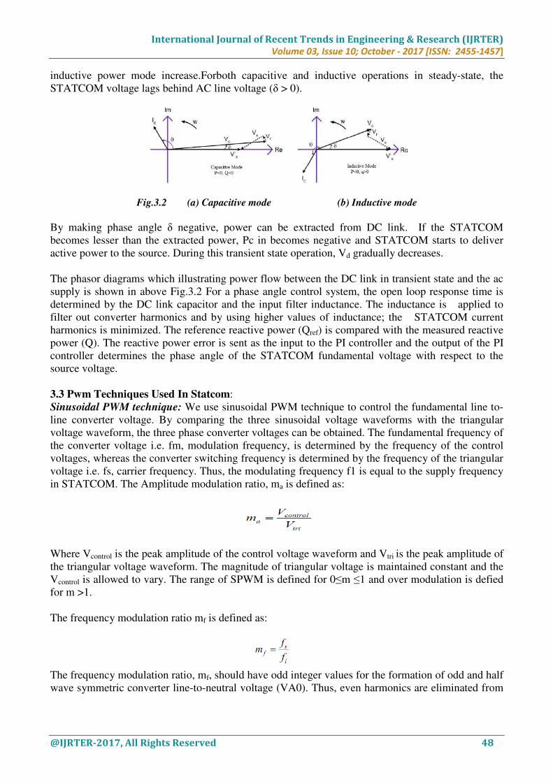
inductive power mode increase.Forboth capacitive and inductive operations in steady-state, the
STATCOM voltage lags behind AC line voltage (δ > 0).
Fig.3.2 (a) Capacitive mode (b) Inductive mode
By making phase angle δ negative, power can be extracted from DC link. If the STATCOM
becomes lesser than the extracted power, Pc in becomes negative and STATCOM starts to deliver
active power to the source. During this transient state operation, Vd gradually decreases.
The phasor diagrams which illustrating power flow between the DC link in transient state and the ac
supply is shown in above Fig.3.2 For a phase angle control system, the open loop response time is
determined by the DC link capacitor and the input filter inductance. The inductance is applied to
filter out converter harmonics and by using higher values of inductance; the STATCOM current
harmonics is minimized. The reference reactive power (Qref) is compared with the measured reactive
power (Q). The reactive power error is sent as the input to the PI controller and the output of the PI
controller determines the phase angle of the STATCOM fundamental voltage with respect to the
source voltage.
3.3 Pwm Techniques Used In Statcom:
Sinusoidal PWM technique: We use sinusoidal PWM technique to control the fundamental line to-
line converter voltage. By comparing the three sinusoidal voltage waveforms with the triangular
voltage waveform, the three phase converter voltages can be obtained. The fundamental frequency of
the converter voltage i.e. fm, modulation frequency, is determined by the frequency of the control
voltages, whereas the converter switching frequency is determined by the frequency of the triangular
voltage i.e. fs, carrier frequency. Thus, the modulating frequency f1 is equal to the supply frequency
in STATCOM. The Amplitude modulation ratio, ma is defined as:
Where Vcontrol is the peak amplitude of the control voltage waveform and Vtri is the peak amplitude of
the triangular voltage waveform. The magnitude of triangular voltage is maintained constant and the
Vcontrol is allowed to vary. The range of SPWM is defined for 0≤m ≤1 and over modulation is defied
for m >1.
The frequency modulation ratio mf is defined as:
The frequency modulation ratio, mf, should have odd integer values for the formation of odd and half
wave symmetric converter line-to-neutral voltage (VA0). Thus, even harmonics are eliminated from
International Journal of Recent Trends in Engineering & Research (IJRTER)
Volume 03, Issue 10; October - 2017 [ISSN: 2455-1457]
@IJRTER-2017, All Rights Reserved 49
the VA0 waveform. Also, to eliminate the harmonics we choose odd multiples of m.The converter
output harmonic frequencies can be given as:
f = (jm ± k) f
The relation between the fundamental component of the line-to-line voltage (VA0) and the
amplitude modulation ratio ma can be gives as:
From which, we can see that Vao varies linearly with respect to m irrespective of m.
The fundamental component converter line-to-line voltage can be expressed as:
In this type of PWM technique, we observe switching harmonics in the high frequency range around
the switching frequency and its multiples in the linear range. From above equation, we can see that
the amplitude of the fundamental component of the converter line-to-line voltage is 0.612m V. But
for square wave operation, we know the amplitude to be 0.78V. Thus, in the linear range the
maximum amplitude of fundamental frequency component is reduced. This can be solved by over
modulation of the converter voltage waveform, which can increase the harmonics in the sidebands of
the converter voltage waveform. Also, the amplitude of VLL1 varies nonlinearly with m and also
varies with m in over modulation as given In a Constant DC Link Voltage Scheme the
STATCOM regulates the DC link voltage value to a fixed one in all modes of operation.
This fixed value is determined by the peak STATCOM fundamental voltage from the full
inductive mode of operation to full capacitive mode at minimum and maximum voltage supply.
Therefore, for 0 ≤ ma ≤ 1; the fundamental voltage is varied by varying ma in the linear range.
3.4 Shunt Compensation:
It has long been recognized that the steady-state transmittable power can be increased
and the voltage profile along the line controlled by appropriate reactive shunt compensation. The
purpose of this reactive compensation is to change the natural electrical characteristics of the
transmission line to make it more compatible with the prevailing load demand. Thus, shunt
connected, fixed or mechanically switched reactors are applied to minimize line overvoltage under
light load conditions, and shunt connected, fixed or mechanically switched capacitors are applied to
maintain voltage levels under heavy load conditions.
In this Report, basic considerations to increase the transmittable power by ideal Shunt-
connected var compensation will be reviewed in order to provide a foundation for power electronics-
based compensation and control techniques to meet specific compensation objectives. The ultimate
objective of applying reactive shunt compensation in a transmission system is to increase the
transmittable power. This may be required to improve the steady-state transmission characteristics as
well as the stability of the system. Var compensation is thus used for voltage regulation at the
midpoint (or some intermediate) to segment the transmission line and at the end of the (radial) line to
prevent voltage instability, as well as for dynamic voltage control to increase transient stability and
"damp power oscillations”
International Journal of Recent Trends in Engineering & Research (IJRTER)
Volume 03, Issue 10; October - 2017 [ISSN: 2455-1457]
@IJRTER-2017, All Rights Reserved 50
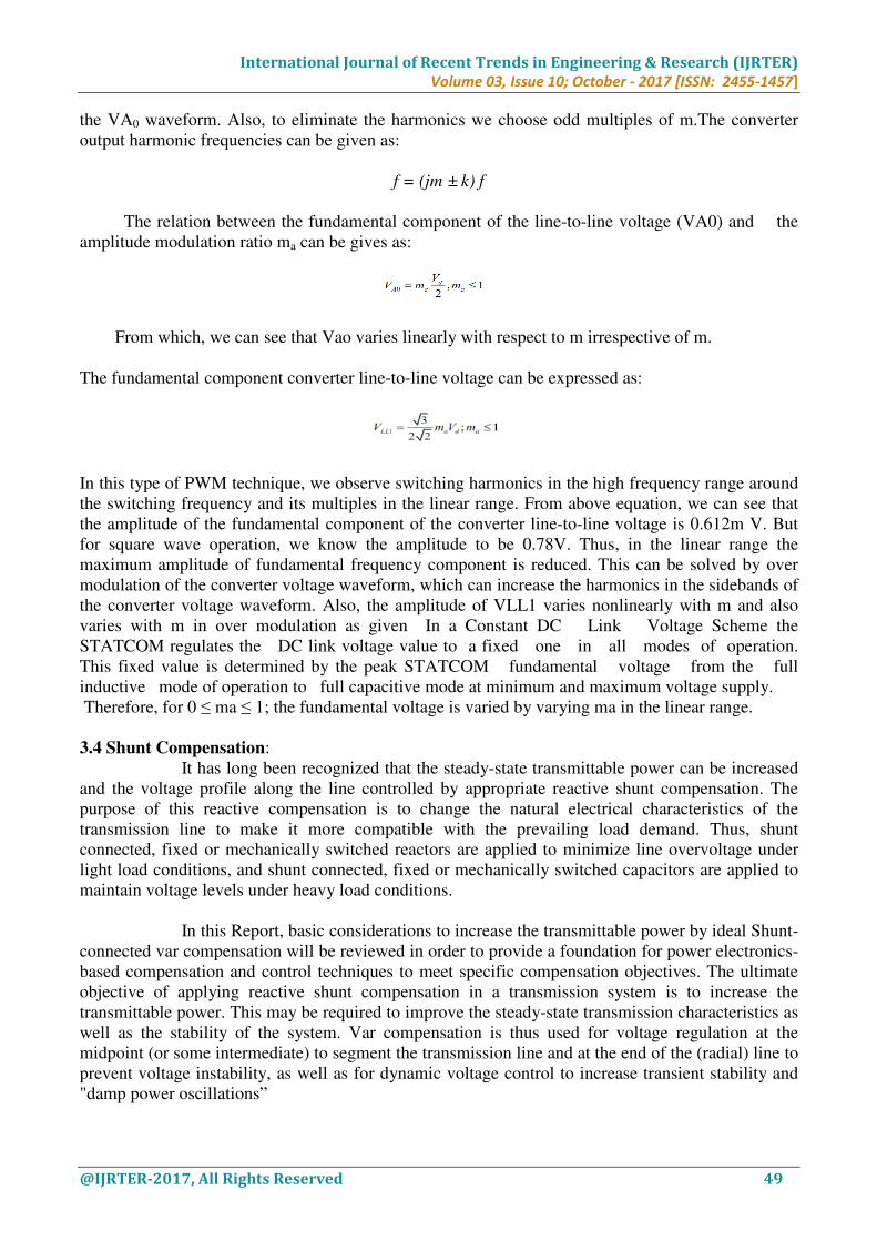
3.5 STATCOM Operating Principle at Fundamental Frequency:
As shown in Fig. 3.4 two impedance loads (one is fixed and the other is connected to the point of
common coupling (PCC) through a switch) are supplied power from a distribution substation with
source voltage VS through a distribution feeder with the impedance RS+JWLS. To regulate the PCC
bus voltage, a STATCOM, which is composed of a VSI and a dc capacitor, is included. The
STATCOM is connected to the PCC through a coupling transformer and a filtering inductor which
can be represented by the series impedance RS+JWLf.
Fig. 3.3 Single-line diagram of a STATCOM connected to a power system
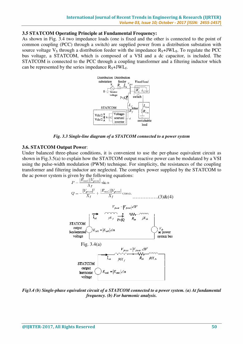
3.6. STATCOM Output Power:
Under balanced three-phase conditions, it is convenient to use the per-phase equivalent circuit as
shown in Fig.3.5(a) to explain how the STATCOM output reactive power can be modulated by a VSI
using the pulse-width modulation (PWM) technique. For simplicity, the resistances of the coupling
transformer and filtering inductor are neglected. The complex power supplied by the STATCOM to
the ac power system is given by the following equations:
…………….(3)&(4)
Fig. 3.4(a)
Fig3.4 (b) Single-phase equivalent circuit of a STATCOM connected to a power system. (a) At fundamental
frequency. (b) For harmonic analysis.

International Journal of Recent Trends in Engineering & Research (IJRTER)
Volume 03, Issue 10; October - 2017 [ISSN: 2455-1457]
@IJRTER-2017, All Rights Reserved 51
Fig3.5. PWM modulation process with a trailing-edge saw-toothed waveform and the STATCOM output
voltage to the neutral N of the dc capacitor.
It is obvious from (3) and (4) that the STATCOM real power output and reactive power
output can be controlled by either its output voltage magnitude or its phase angle or both. In the
design of a STATCOM controller, the reactive power output is of major concern to us since the
negative of simply gives us the real power that must be supplied by the ac bus to the STATCOM in
order to cover the converter loss and transformer and filter loss.
IV. SIMULATION RESULTS
To examine the effectiveness of the proposed analytical approach to the analysis of the line to neutral
harmonic voltage and the proposed STATCOM controller with the steady state modulation-index
regulator and transient modulation index controller, the system in Fig. 4.1 was simulated using
MATLAB /Simulink. In addition, a prototype STATCOM for the simple power distribution system
in Fig. 4.1 has been set up in the laboratory. The simulation and experimental results of the proposed
STATCOM controller at steady state. The harmonic spectra of the STATCOM output voltage and
current from the analytical harmonic analysis method, computer simulations and experiments. Note
that the system parameters used in the simulations were the same as those used in the experiments as
described in Table I. Both steady-state performance and dynamic responses were investigated. The
main purpose for the simulations and the experiments is to show that the proposed analytical
approach to the analysis of line to neutral harmonic voltage can perfectly describe the behavior of the
STATCOM harmonics, and the proposed STATCOM controller can generate lower harmonic
voltages and currents than the STATCOM controller with fixed and variable MI at steady state.
Fig5.1 simulink model of proposed STATCOM
International Journal of Recent Trends in Engineering & Research (IJRTER)
Volume 03, Issue 10; October - 2017 [ISSN: 2455-1457]
@IJRTER-2017, All Rights Reserved 52
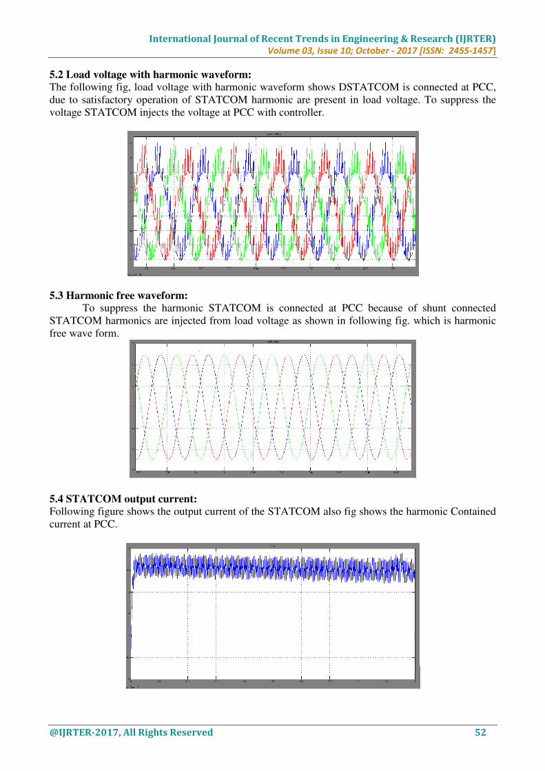
5.2 Load voltage with harmonic waveform:
The following fig, load voltage with harmonic waveform shows DSTATCOM is connected at PCC,
due to satisfactory operation of STATCOM harmonic are present in load voltage. To suppress the
voltage STATCOM injects the voltage at PCC with controller.
5.3 Harmonic free waveform:
To suppress the harmonic STATCOM is connected at PCC because of shunt connected
STATCOM harmonics are injected from load voltage as shown in following fig. which is harmonic
free wave form.
5.4 STATCOM output current:
Following figure shows the output current of the STATCOM also fig shows the harmonic Contained
current at PCC.

International Journal of Recent Trends in Engineering & Research (IJRTER)
Volume 03, Issue 10; October - 2017 [ISSN: 2455-1457]
@IJRTER-2017, All Rights Reserved 53
5.5 Harmonic analysis in FFT source side (phase 1):
Following fig. shows analysis of harmonics in FFT of Vsabc at phase 1. Also fig shows total
harmonic distortion at fundamental frequency (60Hz)
5.6 Harmonic analysis in FFT source side (phase 2):
Following fig. shows analysis of harmonics in FFT of Vsabc at phase 2. Also fig shows total
harmonic distortion at fundamental frequency (60Hz)
International Journal of Recent Trends in Engineering & Research (IJRTER)
Volume 03, Issue 10; October - 2017 [ISSN: 2455-1457]
@IJRTER-2017, All Rights Reserved 54
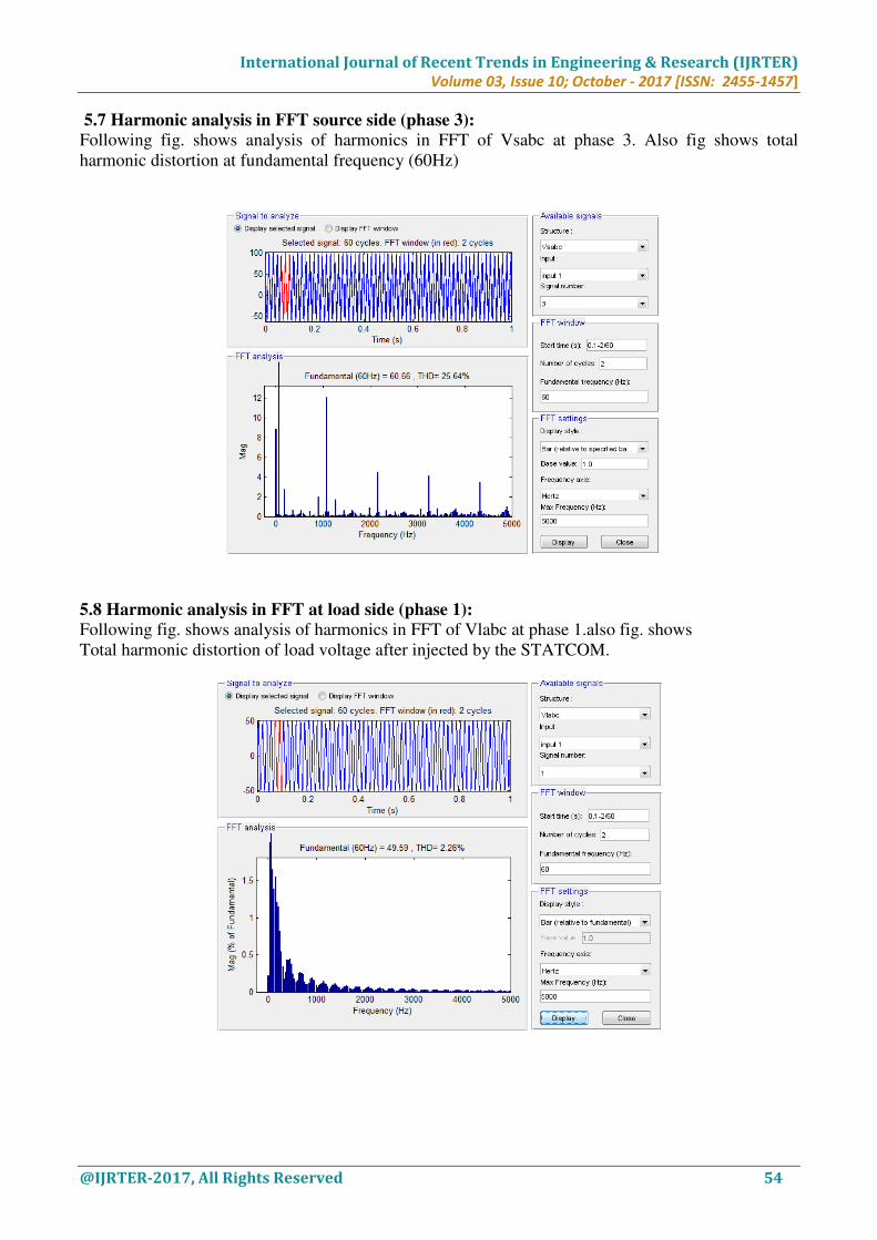
5.7 Harmonic analysis in FFT source side (phase 3):
Following fig. shows analysis of harmonics in FFT of Vsabc at phase 3. Also fig shows total
harmonic distortion at fundamental frequency (60Hz)
5.8 Harmonic analysis in FFT at load side (phase 1):
Following fig. shows analysis of harmonics in FFT of Vlabc at phase 1.also fig. shows
Total harmonic distortion of load voltage after injected by the STATCOM.
International Journal of Recent Trends in Engineering & Research (IJRTER)
Volume 03, Issue 10; October - 2017 [ISSN: 2455-1457]
@IJRTER-2017, All Rights Reserved 55
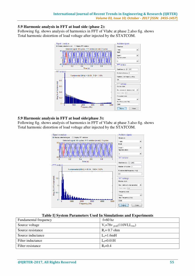
5.9 Harmonic analysis in FFT at load side (phase 2):
Following fig. shows analysis of harmonics in FFT of Vlabc at phase 2.also fig. shows
Total harmonic distortion of load voltage after injected by the STATCOM.
5.9 Harmonic analysis in FFT at load side(phase 3):
Following fig. shows analysis of harmonics in FFT of Vlabc at phase 3.also fig. shows
Total harmonic distortion of load voltage after injected by the STATCOM.
Table I] System Parameters Used In Simulations and Experiments Fundamental frequency f=60 hz
Source voltage Vs=78v peak(110VLLrms)
Source resistance Rs= 0.7 ohm
Source inductance Ls=1.6mH
Filter inductance Lf=0.01H
Filter resistance Rf=0.4

International Journal of Recent Trends in Engineering & Research (IJRTER)
Volume 03, Issue 10; October - 2017 [ISSN: 2455-1457]
@IJRTER-2017, All Rights Reserved 56
Switching frequency fc=1920hz
DC capacitor capacitance C=2200microf
Estimated inverter loss Rp=5000ohm
Reactance of fixed RL load LL=40mH
Resistance of fixed RL load RL=8.4 ohm
Reactance of switched RL LLSW=35.5mH
Resistance of switched RL RLSW=7ohm
Sampling frequency Fs=15360Hz
Table ii] System Eigen Values at Full Load:
System with STATCOM but
without controller
System with STATCOM and with AC voltage controller(K1=15,
K2= 15,K3=10,K4=50 ,K5=-1.23,and K6=-60 )
-227 j377 -216 j377
-85 j377 -2070,-420
-0.187 -7.94
-9.06 j9.06
-1,-1
V. CONCLUSION
This project focuses on harmonic reduction in ac system with the use of STATCOM controller. Here
we used simulation to see different parameters related to harmonic spectra. A STATCOM controller,
which comprises an ac voltage controller, a current regulator, a steady-state modulation-index
regulator, and a transient modulation-index controller, has been proposed in this work. Through the
fast adjustment of the modulation index during the transient period, the ac bus voltage can be
regulated in a very efficient manner since the STATCOM reactive power output can be modulated
rapidly. The steady-state harmonics generated by the STATCOM can be kept minimal as the
modulation index is held constant at the reference value (MI*=1 in this work) at steady state by the
steady-state modulation-index regulator. By comparing the harmonic spectra for the proposed
STATCOM controller and those for the STATCOM controller with fixed Vdc* and variable MI, it has
been concluded that the proposed STATCOM controller generates lower harmonic contents than the
STATCOM controller with fixed Vdc* and variable MI.
VI. FUTURE SCOPE
We can implement this project in hardware by using IGBT driving circuit.
REFERENCES I. N. G.Hingorani and L. Gyugyi, Understanding FACTS. New York: IEEE Press, 2000.
II. C. Schauder, E. Stacey, M. Lund, L. Gyugyi, L. Kovalsky, A. Keri, A. Mehraban, and A. Edris, “AEP UPFC
project: Installation, commissioning and operation of the _160 MVA STATCOM (Phase I),” IEEE Trans.
Power Del., vol. 13, no. 4, pp. 1530–1535, Oct. 1998.
III. G. F. Reed, J. E. Greaf, T. Matsumoto, Y. Yonehata, M. Takeda, T. Aritsuka, Y. Hamasaki, F. Ojima, A. P.
Sidell, R. E. Chervus, and C. K. Nebecker, “Application of a 5 MVA, 4.16 kV D-STATCOM system for
voltage flicker compensation at Seattle iron and metals,” in Proc. IEEE Power Eng. Soc. Summer Meeting,
2000, pp. 1605–1611.
IV. C. Schauder and H. Mehta, “Vector analysis and control of advanced static VAR compensators,” Proc. Inst.
Elect. Eng. C, vol. 140, pp. 299–306, Jul. 1993.
V. L. Moran, P. D. Ziogas, and G. Joos, “A solid-state high-performance reactive-power compensator,” IEEE
Trans. Ind. Appl., vol. 29, no. 5, pp. 969–978, Sep./Oct. 1993.
VI. P. W. Lehn and M. R. Iravani, “Experimental evaluation of STATCOM closed loop dynamics,” IEEE Trans.
Power Del., vol. 13, no. 4, pp. 1378–1384, Oct. 1998.
International Journal of Recent Trends in Engineering & Research (IJRTER)
Volume 03, Issue 10; October - 2017 [ISSN: 2455-1457]
@IJRTER-2017, All Rights Reserved 57
VII. G. Ledwich and A. Ghosh, “A flexible DSTATCOM operating in voltage or current control mode,” Proc. Inst.
Elect. Eng., Gen. Transm. Distrib., vol. 149, pp. 215–224, Mar. 2002.
VIII. G. Escobar,A.M. Stankovic, and P. Mattavelli, “An adaptive controller in stationary reference frame for D-
STATCOM in unbalanced operation,” IEEE Trans. Ind. Electron., vol. 51, no. 2, pp. 401–409, Apr.
IX. C. Schauder, M. Gernhardt, E. Stancey, T. Lemak, L. Gyugyi, T. W. Cease, and A. Edris, “Operation of _100
MVR STATCON,” IEEE Trans. Power Del., vol. 17, no. 4, pp. 1805–1811, Oct. 2002.
X. K. K. Sen, “STATCOM-Static synchronous COMpensator: Theory, modeling, and applications,” in Proc.
IEEE Power Eng. Soc. Winter Meeting, 1999, pp. 1177–1183.
XI. C. K. Sao, P. W. Lehn, M. R. Iravani, and J. A. Martinez, “Abenchmark system for digital time-domain
simulation of a pulse-width-modulated D-STATCOM,” IEEE Trans. Power Del., vol. 17, no. 4, pp. 1113–
1120, Oct. 2002.
XII. P. W. Lehn, “Exact modeling of the voltage source converter,” IEEE Trans. Power Del., vol. 17, no. 1, pp.
217–222, Jan. 2002.
XIII. M. Mohaddes, A. M. Gole, and S. Elez, “Steady state frequency response of STATCOM,” IEEE Trans. Power
Del., vol. 16, no. 1, pp. 18–23, Jan. 2001.
XIV. A. R.Wood and C. M. Osauskas, “A linear frequency-domain model of a STATCOM,” IEEE Trans. Power
Del., vol. 19, no. 3, pp. 1410–1418, Jul. 2004.


![An Unbalanced voltage Compensation Strategy for Islanded ... · for example, static var compensator (STATCOM) [2], series active power filter [3] and shunt active power filter [4]](https://img.pdfslide.us/doc/110x75/5ec37cee6f2e09596744a3be/an-unbalanced-voltage-compensation-strategy-for-islanded-for-example-static.jpg)