Embed Size (px)
Citation preview
2748 IEEE PHOTONICS TECHNOLOGY LETTERS, VOL. 17, NO. 12, DECEMBER 2005
1.6-Tb/s (40 40 Gb/s) Transmission Over44; . . . ;94 km of SSMF With Adaptive
Chromatic Dispersion CompensationS. Bhandare, Member, IEEE, D. Sandel, A. Hidayat, A. F. Abas, H. Zhang, F. Wüst, B. Milivojevic,
R. Noé, Member, IEEE, M. Guy, M. Lapointe, and Y. Painchaud
Abstract—Full-band 1.6-Tb/s adaptive chromatic dispersioncompensation is demonstrated for the first time. A multichanneltunable dispersion compensator is automatically controlled byarrival time detection on one out of 40 wavelength-division-multi-plexed transmitted channels.
Index Terms—Arrival time detection, chromatic dispersion(CD), optical fiber transmission, tunable dispersion compensator.
I. INTRODUCTION
THE upgrading of existing standard single-mode fiber(SSMF) links to 40 Gb/s per wavelength-division-multi-
plexed (WDM) channel presently requires measurement of fiberdispersion and its subsequent compensation by tailored lengthsof dispersion-compensating fiber. To avoid this costly processand to improve network reconfigurability, operators would liketo have adaptive dispersion compensators. For cost reasons,there is strong interest in a periodic frequency response andmultichannel tunable dispersion compensation [1]–[4]. Herewe report, for the first time to our knowledge, on full-bandchromatic dispersion (CD) compensation at 40 Gb/s per WDMchannel, using single multichannel, thermally tunable fiberBragg grating-based, adaptive dispersion compensator that wasinitially designed for operation at 10 Gb/s.
II. TRANSMISSION SETUP
Fig. 1 shows the 40 40 Gb/s transmission setup, similar to[5]. The pseudorandom binary sequence (PRBS) dataat 40 Gb/s is obtained from an experimental 16 : 1 multiplexerthat combines 16 2.5-Gb/s subchannels mutually delayed bymultiples of 8 bits. The electrical multiplexer introduces toomuch intersymbol interference in longer bit patterns and doesnot allow their error-free transmission, not even back-to-back(electrically). PRBS data is modulated onto 40 WDM channels
THz) with 100-GHz channel spacing using adual-drive Mach–Zehnder modulator. The modulation format is
Manuscript received July 18, 2005; revised August 29, 2005.S. Bhandare, D. Sandel, A. Hidayat, A. F. Abas, H. Zhang, F. Wüst, B. Milivo-
jevic, and R. Noé are with the Department of Optical Communication and HighFrequency Engineering, University of Paderborn, 33098 Paderborn, Germany(e-mail: [email protected]; [email protected]).
M. Guy, M. Lapointe, and Y. Painchaud are with TeraXion, Sainte-Foy, QCG1P 4S8, Canada (e-mail: [email protected]; [email protected];[email protected]).
Digital Object Identifier 10.1109/LPT.2005.859522
Fig. 1. 40� 40 Gb/s transmission setup with adaptive multichannel tunableCD compensation.
either carrier suppressed return-to-zero amplitude-shift keying(CSRZ-ASK), with a chirp of 0.22 for experimental conve-nience (because available values of radio-frequency attenuationyielded optimum back-to-back sensitivity for unequal modu-lation amplitudes at the two modulator inputs), or zero-chirpnonreturn-to-zero differential phase-shift keying (NRZ-DPSK).Another Mach–Zehnder modulator driven at 20 GHz carves67% CSRZ pulses for ASK modulation. Transmitted power is2 dBm per channel.
The signals are transmitted over various lengths of SSMFto the receiver. A fiber Bragg grating-based multichannel dis-persion compensator (MTDC) is inserted by means of a op-tical circulator after the optical preamplifier. Dispersion and itsslope are tuned simultaneously by a thermal gradient to matchSSMF lengths between 44 and 94 km. The MTDC has a totalof 51 channels with a bandwidth of at least 35 GHz separatedby 100 GHz. Thermal tuning is possible from 700 to morethan 1500 ps/nm. Fig. 2 shows reflectivity, group delay, andmidchannel dispersions versus wavelength when the dispersionat 194 THz is tuned to about 1350 ps/nm. A representativeclose-up of the group delay is shown in Fig. 3. The averagedgroup delay ripple in a 25-pm spectral window for each channelof this MTDC typically is about 7 ps [4]. Polarization-modedispersion (PMD) is usually as low as 2 ps in other devices ofthis type but this particular device had a PMD of 5 ps. Insertionloss of the compensator including the loss of the optical circu-lator is 5 dB. Using the same fabrication process, compen-sators with other dispersion slopes, or smaller tunability com-
1041-1135/$20.00 © 2005 IEEE
Authorized licensed use limited to: UNIVERSITATSBIBLIOTHEK PADERBORN. Downloaded on May 18,2010 at 07:32:43 UTC from IEEE Xplore. Restrictions apply.

BHANDARE et al.: 1.6 Tb/s (40 40 Gb/s) TRANSMISSION OVER 44 94 km 2749
Fig. 2. Reflectivity, group delay, and midchannel dispersions versuswavelength at �1350-ps/nm midband dispersion.
Fig. 3. Close-up of group delay versus wavelength at various dispersionsettings.
Fig. 4. Dispersion setting dependent narrowing of optical spectrum of a WDMchannel by multichannel compensator.
bined with larger bandwidth, could be designed for long-haulsystems [6].
Fig. 4 shows how the bandwidth limitation of the com-pensator, which was initially designed for 10-Gb/s operation,increases with the compensated fiber length. This bandwidthlimitation causes excess transmission penalties which limitperformance at high dispersion settings.
The dispersion-compensated signals pass a WDM demulti-plexer, a 40 : 1 fiber switch, and subsequent erbium-doped fiberamplifiers (EDFAs) as well as a 2-nm-wide tunable bandpassfilter (not shown) for removal of broad-band noise. The detected
Fig. 5. CD detection readout versus actual dispersion. Inset: RZ-DPSK eyediagram at 147 ps/nm resulting from interferometer output signal difference iscompletely closed, yet the sign of CD is correctly measured.
photocurrent is stabilized by a feedback loop that controls thepump current of the last EDFA. For ASK, the signal is detectedin a single photodetector. For DPSK, a temperature-stabilizedall-fiber Mach–Zehnder interferometer with a 25-ps delay is in-serted, and two differentially connected photodiodes are usedfor balanced detection. The receiver interferometer is stabilizedusing a lock-in detection scheme. A standard clock-and-data re-covery (CDR) with 20-GHz clock signal is used. Bit-error-rate(BER) performance is almost identical in even and odd datasubchannels.
A small sinusoidal 5-MHz pump current modulation is ap-plied to the 194.0-THz transmitter laser. It causes a 400-MHzpeak-to-peak frequency modulation and a 2% amplitude mod-ulation. In the presence of CD, FM modulation causes a smallarrival time modulation that is indicated by the clock phase errorsignal in the clock recovery phase-locked loop (PLL). For ar-rival time detection, a low frequency power monitor photodioderecovers the 5-MHz amplitude modulation and provides a ref-erence signal for the lock-in detection of the clock phase errorsignal. After amplification and bandpass filtering, the arrivaltime detection signal is multiplied with the reference signal ina digital signal processor. Due to the lock-in detection scheme,the multiplier output signal is directly proportional to the ex-perienced residual dispersion, including its sign [7]. An earlierobtained CD readout characteristic as a function of true residualdispersion is shown in Fig. 5, here for RZ-DPSK. The sign ofCD readout is correct even when transmission is no longer pos-sible, as is illustrated by the completely closed eye diagram(inset). The small offset at zero dispersion is due to the imperfec-tion of the experimental 40-Gb/s CDR used in this experiment.It is quite stable and can, therefore, be subtracted.
For initial signal acquisition, the CD setting is swept and thelocking of the clock PLL is monitored. Then the dispersion istuned into the center of the PLL locking range. Subsequentlythe dispersion is held, and tracked if necessary, by integratingthe CD error signal. In a commercial system, the signals ofthe 194.0-THz receiver would be utilized to control the com-pensator, and those of another (near) midband channel, also ifequipped with laser pump current modulation, would constitutea reserve in case of a channel failure.
Temporal variations of CD are automatically tracked whenthe 194.0-THz channel is received and we freeze the integratoroutput signal CD control signal when other channels are se-lected. The electrical heating/cooling power required to control
Authorized licensed use limited to: UNIVERSITATSBIBLIOTHEK PADERBORN. Downloaded on May 18,2010 at 07:32:43 UTC from IEEE Xplore. Restrictions apply.
2750 IEEE PHOTONICS TECHNOLOGY LETTERS, VOL. 17, NO. 12, DECEMBER 2005
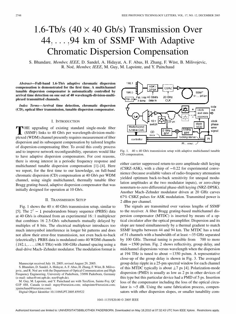
Fig. 6. Received optical spectra for 40 WDM channels before the opticalpreamplifier: CSRZ-ASK (bottom) and NRZ-DPSK (top).
Fig. 7. Q-factors for CSRZ-ASK and NRZ-DPSK at various transmissiondistances, in each case for 40 WDM channels.
the CD compensator is 10 W. The thermal scan takes 10 min,and the control time constant is about 30 s, but control speedwas not optimized. A proportional integral derivative controllershould work better.
III. TRANSMISSION RESULTS
Fig. 6 shows the received optical spectra for 40 WDM chan-nels before the optical preamplifier for CSRZ-ASK and NRZ-DPSK modulation format.
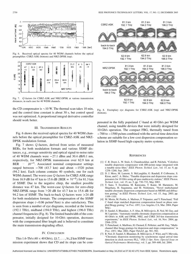
Fig. 7 shows -factors, derived from series of measuredBERs, for both modulation formats and various SSMF dis-tances, e.g., average sensitivity and optical signal-to-noise ratioof 40 WDM channels were 27.1 dBm and 30.4 dB/0.1 nm,respectively, for NRZ-DPSK transmission over 62.9 km atBER . Associated nominal compensator settingsranged between 700 (43.7 km) and about 1520 ps/nm(94.2 km). Each column contains 40 symbols, one for eachWDM channel. The worst-case -factors for CSRZ-ASK rangefrom 16.9 dB for 47 km to 15.6 dB BER for 81.3 kmof SSMF. Due to the negative chirp, the smallest possibledistance was 47 km. The worst-case -factors for zero-chirpNRZ-DPSK range from 20 dB for 43.7 km to 15.6 dB for94.2 km of SSMF. The back-to-back -factors were 24 dBfor both modulation formats. The compensation of the SSMFdispersion slope ( 0.06 ps/nm /km) is also satisfactory. Thisis seen from a number of eye diagrams, recorded at the lowest(192.1 THz), midband (194.0 THz), and highest (196.0 THz)channel frequencies (Fig. 8). The limited bandwidth of the com-pensator, initially designed for 10-Gb/s operation, decreaseswith the compensated fiber length and is believed to constitutethe main transmission-degrading effect.
IV. CONCLUSION
This 1.6-Tb/s (40 40 Gb/s), km SSMF trans-mission experiment shows that CD and its slope can be com-
Fig. 8. Exemplary eye diagrams for CSRZ-ASK (top) and NRZ-DPSK(bottom).
pensated in the fully populated -band at 40 Gb/s per WDMchannel, using tunable devices that were initially designed for10-Gb/s operation. The compact FBG, thermally tuned from
700 to 1500 ps/nm combined with the arrival time detectionscheme are suitable for a low-cost dispersion compensation so-lution in SSMF-based high-capacity metro systems.
REFERENCES
[1] C. R. Doerr, L. W. Stulz, S. Chandrasekhar, and R. Pafchek, “Colorlesstunable dispersion compensator with 400-ps/nm range integrated witha tunable noise filter,” IEEE Photon. Technol. Lett., vol. 15, no. 9, pp.1258–1260, Sep. 2003.
[2] D. J. Moss, M. Lamont, S. McLaughlin, G. Randall, P. Colbourne, S.Kiran, and C. A. Hulse, “Tunable dispersion and dispersion slope com-pensators for 10 Gb/s using all-pass multicavity etalons,” IEEE Photon.Technol. Lett., vol. 15, no. 5, pp. 730–732, May 2003.
[3] T. Sano, T. Iwashima, M. Katayama, T. Kanie, M. Harumoto, M.Shigehara, H. Suganuma, and M. Nishimura, “Novel multichanneltunable chromatic dispersion compensator based on MEMS and diffrac-tion grating,” in IEEE Photon. Technol. Lett., vol. 15, Aug. 2003, pp.1109–1101.
[4] M. Morin, M. Poulin, A. Mailoux, F. Trépanier, and Y. Painchaud, “FullC-band slope matched dispersion compensation based on phase sam-pled Bragg grating,” in Proc. OFC, Los Angeles, CA, Mar. 2004, PaperWK1.
[5] D. Sandel, S. Bhandare, A. F. Abas, B. Milivojevic, R. Noé, M. Guy, andM. Lapointe, “Automatic tunable chromatic dispersion compensation at40 Gbit/s in ASK and DPSK, NRZ, and CSRZ 263-km transmissionexperiments,” in IEEE Photon. Technol. Lett., vol. 16, Nov. 2004, pp.2568–2570.
[6] Y. Painchaud, A. Mailloux, H. Chotard, É. Pelletier, and M. Guy, “Multi-channel fiber bragg gratings for dispersion and slope compensation,” inProc. OFC, Mar. 2002, Paper ThAA5, pp. 581–582.
[7] R. Noé, D. Sandel, S. Bhandare, B. Milivojevic, F. Wüst, and V. Mirvoda,“Chromatic dispersion monitoring by synchronous signal arrival timedetection in clock recovery PLL,” OSA J. Opt. Netw. (Special Issue onOptical Performance Monitoring), vol. 3, pp. 589–600, Jul. 2004.
Authorized licensed use limited to: UNIVERSITATSBIBLIOTHEK PADERBORN. Downloaded on May 18,2010 at 07:32:43 UTC from IEEE Xplore. Restrictions apply.