Embed Size (px)
Citation preview
Miniature Modular Manufacturing Systems and Eficiency Analysis of the Systems 521
Miniature Modular Manufacturing Systems and Eficiency Analysis of the Systems
Nozomu Mishima, Kondoh Shinsuke, Kiwamu Ashida and Shizuka Nakano
x
Miniature Modular Manufacturing Systems and Efficiency Analysis
of the Systems
Nozomu Mishima, Kondoh Shinsuke, Kiwamu Ashida and Shizuka Nakano
Advanced Manufacturing Research Institute, AIST Japam
1. Introduction
In recent world, there are many small mechanical parts and products are used for mobile phones, medical devices, home appliances, and so on. However, manufacturing systems for those devices are large and complex. Manufacturing systems are not goals. So, manufacturing systems should be small as possible within satisfying requirements in the production. In addition, every activity in manufacturing industry is required to be environmentally benign, these days. Being environmental consciousness a big trend in manufacturing technology, space occupied and energy used by conventional manufacturing systems became considered as big wastes. Among all the energy usage of a manufacturing system, just a small portion is used for cutting and the rest for moving heavy structures of machines or generating heat. So, a large machine represents considerable waste. As a countermeasure for the situation, AIST (National Institute of Advanced Industrial Science and Technology) proposed a concept of a microfactory that consists of tiny machine tools and robots. However, for the first decade, the concept had been only a figure indicating a future application after micro-machine technology has been developed. Miniaturization of machine tools to size compatible to the target products without compromising the machining tolerances leads to enormous savings in energy, space, and resources. It also makes it easy to change the production layout of the factory. In 1996, AIST developed the first prototype of the miniaturized machine tool; a micro-lathe [1], with considerable metal cut capability and substantial energy saving effects. The machining capability of the lathe was far better than we expected in advance. This success of the micro lathe was the driving force to prototype a whole factory that performs a series of fabrication and assembly on a desktop. In 1999, AIST designed and established a machining microfactory, which consisted of afore-mentioned micro-lathe, other small size machine tools and manipulators for parts handling and assembly. Ttest results showed that a downsized manufacturing system could be a feasible option for micro mechanical fabrication. Some other miniature manufacturing systems [4-6] have been proposed since then and the concept has now become quite common.
24
www.intechopen.com
Robot Manipulators, Trends and Development522
Downsizing of manufacturing systems could potentially reduce environmental impacts and manufacturing costs, especially for diverse-types-and-small-quantity production. However, since no studies have been carried out to evaluate the effect of downsizing quantitatively, the actual potential of such systems to reduce environmental impacts in micro mechanical fabrication is still unknown. In addition, it was found that aforementioned miniature systems had some problems in the aspect of productivity and flexibility, since they mainly focused on reducing the size. In 2007, AIST developed the new concept of downsized manufacturing system called “on-demand MEMS factory.” And a simple method for evaluating the environmental consciousness and productivity to help system configuration design was also proposed. Then AIST compared the evaluation results with that of a conventional manufacturing facility, in order to say that the concept is feasible and hopeful.
2. The First Prototype; Microfactory
2.1 Micro/Meso Mechanical Fabrication
“Microfactory” was a concept of a future manufacturing system as an answer to the situation. It was proposed in the Japanese national R&D project named “Micro Machine Project [1].” The concept of the microfactory was very simple. The development team including one of the authors thought if it is possible to build “a super-miniature factory” for micro mechanical fabrication, environmental impact of manufacturing can be decreased greatly. In 1999, AIST developed the first prototype of a microfactory that consists of miniature machine tools and miniature manipulators. (Fig.1) The microfactory was able to perform a series of fabrication and assembly within a small desktop [2,3]. The result of the test production led us to conclude that the microfactory had considerable capability of micro mechanical fabrication. The development team insisted that the microfactory would reduce environmental impact and costs of “diverse-types-and-small-quantity production”, “one-off production” or “variety-and-variant production”. Since the smallness of the machines enables flexible layout changes, it can control the increase of the costs when the product designs have been modified. However, since there have been no effort to evaluate efficiency of the microfactory comparing with conventional factory quantitatively, the advantage to reduce environmental impact is still uncertain. The purpose of this report is to explain briefly about the microfactory and propose a simple and useful efficiency index to support system configuration design of microfactory-like system.
2.2 Design of the Microfactory
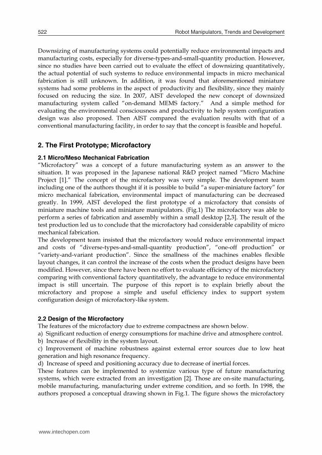
The features of the microfactory due to extreme compactness are shown below. a) Significant reduction of energy consumptions for machine drive and atmosphere control. b) Increase of flexibility in the system layout. c) Improvement of machine robustness against external error sources due to low heat generation and high resonance frequency. d) Increase of speed and positioning accuracy due to decrease of inertial forces. These features can be implemented to systemize various type of future manufacturing systems, which were extracted from an investigation [2]. Those are on-site manufacturing, mobile manufacturing, manufacturing under extreme condition, and so forth. In 1998, the authors proposed a conceptual drawing shown in Fig.1. The figure shows the microfactory
under microscopic vision and master-slave control by an operator to assemble small parts to a product. We tried to prototype the practical microfactory according to the figure.
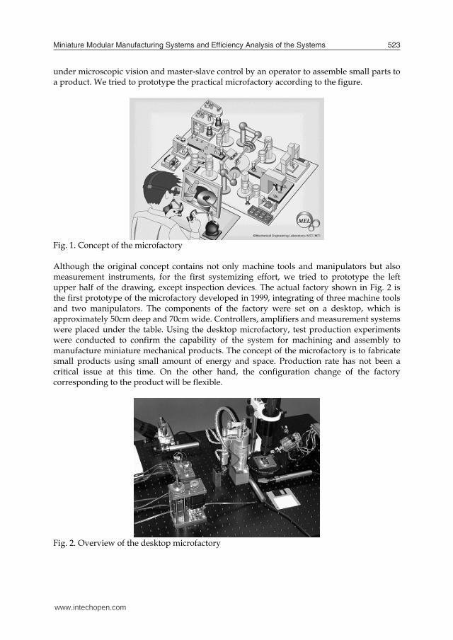
Fig. 1. Concept of the microfactory Although the original concept contains not only machine tools and manipulators but also measurement instruments, for the first systemizing effort, we tried to prototype the left upper half of the drawing, except inspection devices. The actual factory shown in Fig. 2 is the first prototype of the microfactory developed in 1999, integrating of three machine tools and two manipulators. The components of the factory were set on a desktop, which is approximately 50cm deep and 70cm wide. Controllers, amplifiers and measurement systems were placed under the table. Using the desktop microfactory, test production experiments were conducted to confirm the capability of the system for machining and assembly to manufacture miniature mechanical products. The concept of the microfactory is to fabricate small products using small amount of energy and space. Production rate has not been a critical issue at this time. On the other hand, the configuration change of the factory corresponding to the product will be flexible.
Fig. 2. Overview of the desktop microfactory
www.intechopen.com
Miniature Modular Manufacturing Systems and Eficiency Analysis of the Systems 523
Downsizing of manufacturing systems could potentially reduce environmental impacts and manufacturing costs, especially for diverse-types-and-small-quantity production. However, since no studies have been carried out to evaluate the effect of downsizing quantitatively, the actual potential of such systems to reduce environmental impacts in micro mechanical fabrication is still unknown. In addition, it was found that aforementioned miniature systems had some problems in the aspect of productivity and flexibility, since they mainly focused on reducing the size. In 2007, AIST developed the new concept of downsized manufacturing system called “on-demand MEMS factory.” And a simple method for evaluating the environmental consciousness and productivity to help system configuration design was also proposed. Then AIST compared the evaluation results with that of a conventional manufacturing facility, in order to say that the concept is feasible and hopeful.
2. The First Prototype; Microfactory
2.1 Micro/Meso Mechanical Fabrication
“Microfactory” was a concept of a future manufacturing system as an answer to the situation. It was proposed in the Japanese national R&D project named “Micro Machine Project [1].” The concept of the microfactory was very simple. The development team including one of the authors thought if it is possible to build “a super-miniature factory” for micro mechanical fabrication, environmental impact of manufacturing can be decreased greatly. In 1999, AIST developed the first prototype of a microfactory that consists of miniature machine tools and miniature manipulators. (Fig.1) The microfactory was able to perform a series of fabrication and assembly within a small desktop [2,3]. The result of the test production led us to conclude that the microfactory had considerable capability of micro mechanical fabrication. The development team insisted that the microfactory would reduce environmental impact and costs of “diverse-types-and-small-quantity production”, “one-off production” or “variety-and-variant production”. Since the smallness of the machines enables flexible layout changes, it can control the increase of the costs when the product designs have been modified. However, since there have been no effort to evaluate efficiency of the microfactory comparing with conventional factory quantitatively, the advantage to reduce environmental impact is still uncertain. The purpose of this report is to explain briefly about the microfactory and propose a simple and useful efficiency index to support system configuration design of microfactory-like system.
2.2 Design of the Microfactory
The features of the microfactory due to extreme compactness are shown below. a) Significant reduction of energy consumptions for machine drive and atmosphere control. b) Increase of flexibility in the system layout. c) Improvement of machine robustness against external error sources due to low heat generation and high resonance frequency. d) Increase of speed and positioning accuracy due to decrease of inertial forces. These features can be implemented to systemize various type of future manufacturing systems, which were extracted from an investigation [2]. Those are on-site manufacturing, mobile manufacturing, manufacturing under extreme condition, and so forth. In 1998, the authors proposed a conceptual drawing shown in Fig.1. The figure shows the microfactory
under microscopic vision and master-slave control by an operator to assemble small parts to a product. We tried to prototype the practical microfactory according to the figure.
Fig. 1. Concept of the microfactory Although the original concept contains not only machine tools and manipulators but also measurement instruments, for the first systemizing effort, we tried to prototype the left upper half of the drawing, except inspection devices. The actual factory shown in Fig. 2 is the first prototype of the microfactory developed in 1999, integrating of three machine tools and two manipulators. The components of the factory were set on a desktop, which is approximately 50cm deep and 70cm wide. Controllers, amplifiers and measurement systems were placed under the table. Using the desktop microfactory, test production experiments were conducted to confirm the capability of the system for machining and assembly to manufacture miniature mechanical products. The concept of the microfactory is to fabricate small products using small amount of energy and space. Production rate has not been a critical issue at this time. On the other hand, the configuration change of the factory corresponding to the product will be flexible.
Fig. 2. Overview of the desktop microfactory
www.intechopen.com
Robot Manipulators, Trends and Development524
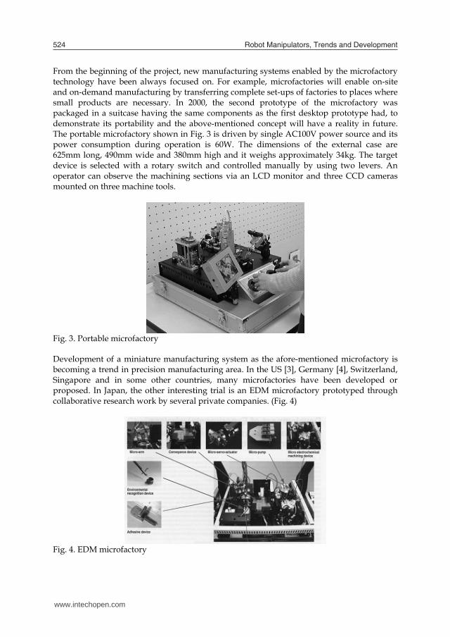
From the beginning of the project, new manufacturing systems enabled by the microfactory technology have been always focused on. For example, microfactories will enable on-site and on-demand manufacturing by transferring complete set-ups of factories to places where small products are necessary. In 2000, the second prototype of the microfactory was packaged in a suitcase having the same components as the first desktop prototype had, to demonstrate its portability and the above-mentioned concept will have a reality in future. The portable microfactory shown in Fig. 3 is driven by single AC100V power source and its power consumption during operation is 60W. The dimensions of the external case are 625mm long, 490mm wide and 380mm high and it weighs approximately 34kg. The target device is selected with a rotary switch and controlled manually by using two levers. An operator can observe the machining sections via an LCD monitor and three CCD cameras mounted on three machine tools.
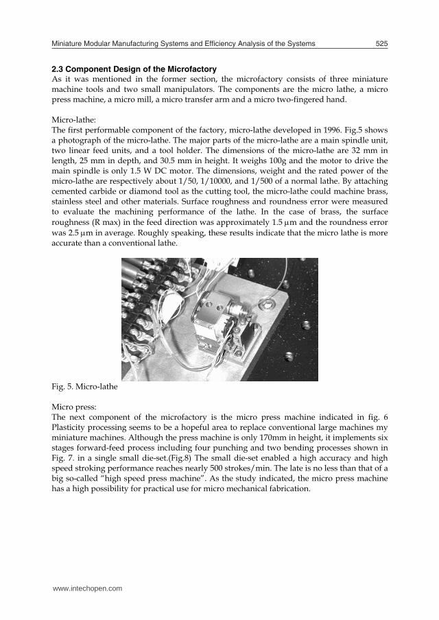
Fig. 3. Portable microfactory Development of a miniature manufacturing system as the afore-mentioned microfactory is becoming a trend in precision manufacturing area. In the US [3], Germany [4], Switzerland, Singapore and in some other countries, many microfactories have been developed or proposed. In Japan, the other interesting trial is an EDM microfactory prototyped through collaborative research work by several private companies. (Fig. 4)
Fig. 4. EDM microfactory
2.3 Component Design of the Microfactory As it was mentioned in the former section, the microfactory consists of three miniature machine tools and two small manipulators. The components are the micro lathe, a micro press machine, a micro mill, a micro transfer arm and a micro two-fingered hand. Micro-lathe: The first performable component of the factory, micro-lathe developed in 1996. Fig.5 shows a photograph of the micro-lathe. The major parts of the micro-lathe are a main spindle unit, two linear feed units, and a tool holder. The dimensions of the micro-lathe are 32 mm in length, 25 mm in depth, and 30.5 mm in height. It weighs 100g and the motor to drive the main spindle is only 1.5 W DC motor. The dimensions, weight and the rated power of the micro-lathe are respectively about 1/50, 1/10000, and 1/500 of a normal lathe. By attaching cemented carbide or diamond tool as the cutting tool, the micro-lathe could machine brass, stainless steel and other materials. Surface roughness and roundness error were measured to evaluate the machining performance of the lathe. In the case of brass, the surface roughness (R max) in the feed direction was approximately 1.5 m and the roundness error was 2.5 m in average. Roughly speaking, these results indicate that the micro lathe is more accurate than a conventional lathe.
Fig. 5. Micro-lathe Micro press: The next component of the microfactory is the micro press machine indicated in fig. 6 Plasticity processing seems to be a hopeful area to replace conventional large machines my miniature machines. Although the press machine is only 170mm in height, it implements six stages forward-feed process including four punching and two bending processes shown in Fig. 7. in a single small die-set.(Fig.8) The small die-set enabled a high accuracy and high speed stroking performance reaches nearly 500 strokes/min. The late is no less than that of a big so-called “high speed press machine”. As the study indicated, the micro press machine has a high possibility for practical use for micro mechanical fabrication.
www.intechopen.com
Miniature Modular Manufacturing Systems and Eficiency Analysis of the Systems 525
From the beginning of the project, new manufacturing systems enabled by the microfactory technology have been always focused on. For example, microfactories will enable on-site and on-demand manufacturing by transferring complete set-ups of factories to places where small products are necessary. In 2000, the second prototype of the microfactory was packaged in a suitcase having the same components as the first desktop prototype had, to demonstrate its portability and the above-mentioned concept will have a reality in future. The portable microfactory shown in Fig. 3 is driven by single AC100V power source and its power consumption during operation is 60W. The dimensions of the external case are 625mm long, 490mm wide and 380mm high and it weighs approximately 34kg. The target device is selected with a rotary switch and controlled manually by using two levers. An operator can observe the machining sections via an LCD monitor and three CCD cameras mounted on three machine tools.
Fig. 3. Portable microfactory Development of a miniature manufacturing system as the afore-mentioned microfactory is becoming a trend in precision manufacturing area. In the US [3], Germany [4], Switzerland, Singapore and in some other countries, many microfactories have been developed or proposed. In Japan, the other interesting trial is an EDM microfactory prototyped through collaborative research work by several private companies. (Fig. 4)
Fig. 4. EDM microfactory
2.3 Component Design of the Microfactory As it was mentioned in the former section, the microfactory consists of three miniature machine tools and two small manipulators. The components are the micro lathe, a micro press machine, a micro mill, a micro transfer arm and a micro two-fingered hand. Micro-lathe: The first performable component of the factory, micro-lathe developed in 1996. Fig.5 shows a photograph of the micro-lathe. The major parts of the micro-lathe are a main spindle unit, two linear feed units, and a tool holder. The dimensions of the micro-lathe are 32 mm in length, 25 mm in depth, and 30.5 mm in height. It weighs 100g and the motor to drive the main spindle is only 1.5 W DC motor. The dimensions, weight and the rated power of the micro-lathe are respectively about 1/50, 1/10000, and 1/500 of a normal lathe. By attaching cemented carbide or diamond tool as the cutting tool, the micro-lathe could machine brass, stainless steel and other materials. Surface roughness and roundness error were measured to evaluate the machining performance of the lathe. In the case of brass, the surface roughness (R max) in the feed direction was approximately 1.5 m and the roundness error was 2.5 m in average. Roughly speaking, these results indicate that the micro lathe is more accurate than a conventional lathe.
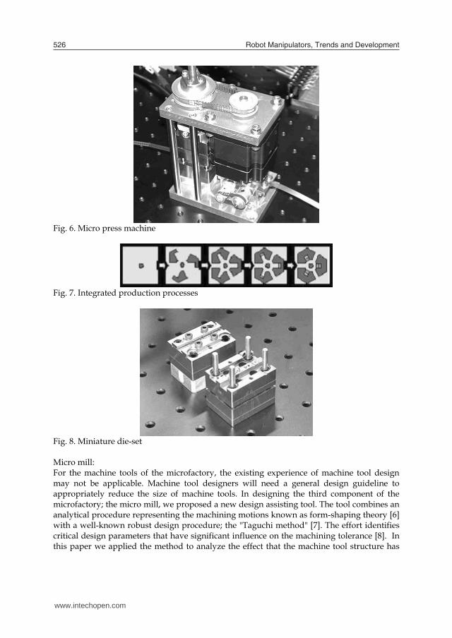
Fig. 5. Micro-lathe Micro press: The next component of the microfactory is the micro press machine indicated in fig. 6 Plasticity processing seems to be a hopeful area to replace conventional large machines my miniature machines. Although the press machine is only 170mm in height, it implements six stages forward-feed process including four punching and two bending processes shown in Fig. 7. in a single small die-set.(Fig.8) The small die-set enabled a high accuracy and high speed stroking performance reaches nearly 500 strokes/min. The late is no less than that of a big so-called “high speed press machine”. As the study indicated, the micro press machine has a high possibility for practical use for micro mechanical fabrication.
www.intechopen.com
Robot Manipulators, Trends and Development526
Fig. 6. Micro press machine
Fig. 7. Integrated production processes
Fig. 8. Miniature die-set Micro mill: For the machine tools of the microfactory, the existing experience of machine tool design may not be applicable. Machine tool designers will need a general design guideline to appropriately reduce the size of machine tools. In designing the third component of the microfactory; the micro mill, we proposed a new design assisting tool. The tool combines an analytical procedure representing the machining motions known as form-shaping theory [6] with a well-known robust design procedure; the "Taguchi method" [7]. The effort identifies critical design parameters that have significant influence on the machining tolerance [8]. In this paper we applied the method to analyze the effect that the machine tool structure has
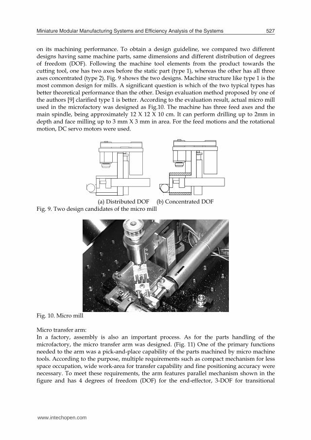
on its machining performance. To obtain a design guideline, we compared two different designs having same machine parts, same dimensions and different distribution of degrees of freedom (DOF). Following the machine tool elements from the product towards the cutting tool, one has two axes before the static part (type 1), whereas the other has all three axes concentrated (type 2). Fig. 9 shows the two designs. Machine structure like type 1 is the most common design for mills. A significant question is which of the two typical types has better theoretical performance than the other. Design evaluation method proposed by one of the authors [9] clarified type 1 is better. According to the evaluation result, actual micro mill used in the microfactory was designed as Fig.10. The machine has three feed axes and the main spindle, being approximately 12 X 12 X 10 cm. It can perform drilling up to 2mm in depth and face milling up to 3 mm X 3 mm in area. For the feed motions and the rotational motion, DC servo motors were used.
(a) Distributed DOF (b) Concentrated DOF Fig. 9. Two design candidates of the micro mill
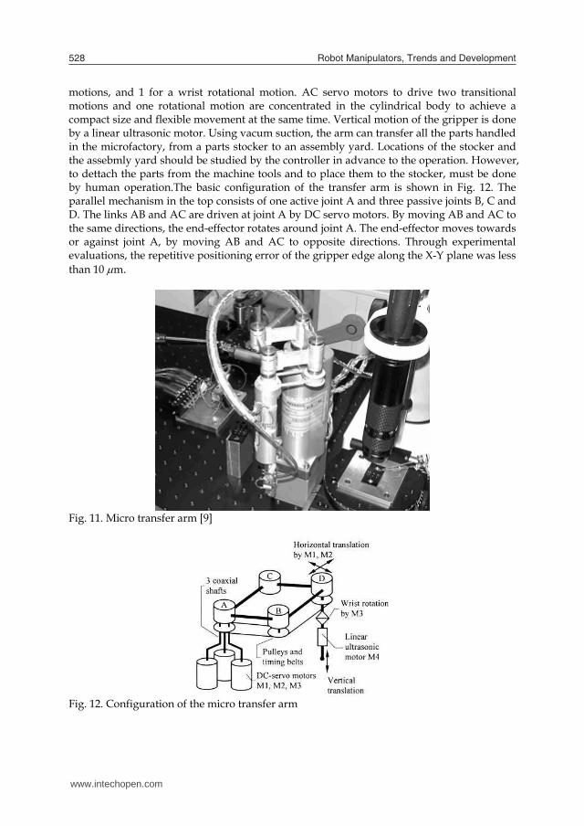
Fig. 10. Micro mill Micro transfer arm: In a factory, assembly is also an important process. As for the parts handling of the microfactory, the micro transfer arm was designed. (Fig. 11) One of the primary functions needed to the arm was a pick-and-place capability of the parts machined by micro machine tools. According to the purpose, multiple requirements such as compact mechanism for less space occupation, wide work-area for transfer capability and fine positioning accuracy were necessary. To meet these requirements, the arm features parallel mechanism shown in the figure and has 4 degrees of freedom (DOF) for the end-effector, 3-DOF for transitional
www.intechopen.com
Miniature Modular Manufacturing Systems and Eficiency Analysis of the Systems 527
Fig. 6. Micro press machine
Fig. 7. Integrated production processes
Fig. 8. Miniature die-set Micro mill: For the machine tools of the microfactory, the existing experience of machine tool design may not be applicable. Machine tool designers will need a general design guideline to appropriately reduce the size of machine tools. In designing the third component of the microfactory; the micro mill, we proposed a new design assisting tool. The tool combines an analytical procedure representing the machining motions known as form-shaping theory [6] with a well-known robust design procedure; the "Taguchi method" [7]. The effort identifies critical design parameters that have significant influence on the machining tolerance [8]. In this paper we applied the method to analyze the effect that the machine tool structure has
on its machining performance. To obtain a design guideline, we compared two different designs having same machine parts, same dimensions and different distribution of degrees of freedom (DOF). Following the machine tool elements from the product towards the cutting tool, one has two axes before the static part (type 1), whereas the other has all three axes concentrated (type 2). Fig. 9 shows the two designs. Machine structure like type 1 is the most common design for mills. A significant question is which of the two typical types has better theoretical performance than the other. Design evaluation method proposed by one of the authors [9] clarified type 1 is better. According to the evaluation result, actual micro mill used in the microfactory was designed as Fig.10. The machine has three feed axes and the main spindle, being approximately 12 X 12 X 10 cm. It can perform drilling up to 2mm in depth and face milling up to 3 mm X 3 mm in area. For the feed motions and the rotational motion, DC servo motors were used.
(a) Distributed DOF (b) Concentrated DOF Fig. 9. Two design candidates of the micro mill
Fig. 10. Micro mill Micro transfer arm: In a factory, assembly is also an important process. As for the parts handling of the microfactory, the micro transfer arm was designed. (Fig. 11) One of the primary functions needed to the arm was a pick-and-place capability of the parts machined by micro machine tools. According to the purpose, multiple requirements such as compact mechanism for less space occupation, wide work-area for transfer capability and fine positioning accuracy were necessary. To meet these requirements, the arm features parallel mechanism shown in the figure and has 4 degrees of freedom (DOF) for the end-effector, 3-DOF for transitional
www.intechopen.com
Robot Manipulators, Trends and Development528
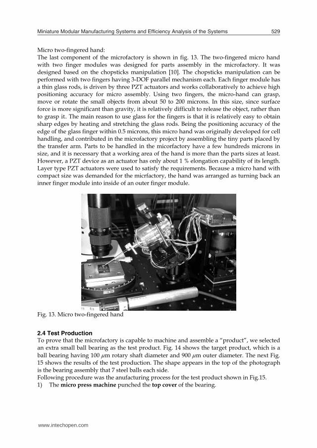
motions, and 1 for a wrist rotational motion. AC servo motors to drive two transitional motions and one rotational motion are concentrated in the cylindrical body to achieve a compact size and flexible movement at the same time. Vertical motion of the gripper is done by a linear ultrasonic motor. Using vacum suction, the arm can transfer all the parts handled in the microfactory, from a parts stocker to an assembly yard. Locations of the stocker and the assebmly yard should be studied by the controller in advance to the operation. However, to dettach the parts from the machine tools and to place them to the stocker, must be done by human operation.The basic configuration of the transfer arm is shown in Fig. 12. The parallel mechanism in the top consists of one active joint A and three passive joints B, C and D. The links AB and AC are driven at joint A by DC servo motors. By moving AB and AC to the same directions, the end-effector rotates around joint A. The end-effector moves towards or against joint A, by moving AB and AC to opposite directions. Through experimental evaluations, the repetitive positioning error of the gripper edge along the X-Y plane was less than 10 m.
Fig. 11. Micro transfer arm [9]
Fig. 12. Configuration of the micro transfer arm
Micro two-fingered hand: The last component of the microfactory is shown in fig. 13. The two-fingered micro hand with two finger modules was designed for parts assembly in the microfactory. It was designed based on the chopsticks manipulation [10]. The chopsticks manipulation can be performed with two fingers having 3-DOF parallel mechanism each. Each finger module has a thin glass rods, is driven by three PZT actuators and works collaboratively to achieve high positioning accuracy for micro assembly. Using two fingers, the micro-hand can grasp, move or rotate the small objects from about 50 to 200 microns. In this size, since surface force is more significant than gravity, it is relatively difficult to release the object, rather than to grasp it. The main reason to use glass for the fingers is that it is relatively easy to obtain sharp edges by heating and stretching the glass rods. Being the positioning accuracy of the edge of the glass finger within 0.5 microns, this micro hand was originally developed for cell handling, and contributed in the microfactory project by assembling the tiny parts placed by the transfer arm. Parts to be handled in the micorfactory have a few hundreds microns in size, and it is necessary that a working area of the hand is more than the parts sizes at least. However, a PZT device as an actuator has only about 1 % elongation capability of its length. Layer type PZT actuators were used to satisfy the requirements. Because a micro hand with compact size was demanded for the micrfactory, the hand was arranged as turning back an inner finger module into inside of an outer finger module.
Fig. 13. Micro two-fingered hand
2.4 Test Production
To prove that the microfactory is capable to machine and assemble a “product”, we selected an extra small ball bearing as the test product. Fig. 14 shows the target product, which is a ball bearing having 100 m rotary shaft diameter and 900 m outer diameter. The next Fig. 15 shows the results of the test production. The shape appears in the top of the photograph is the bearing assembly that 7 steel balls each side. Following procedure was the anufacturing process for the test product shown in Fig.15. 1) The micro press machine punched the top cover of the bearing.
www.intechopen.com
Miniature Modular Manufacturing Systems and Eficiency Analysis of the Systems 529
motions, and 1 for a wrist rotational motion. AC servo motors to drive two transitional motions and one rotational motion are concentrated in the cylindrical body to achieve a compact size and flexible movement at the same time. Vertical motion of the gripper is done by a linear ultrasonic motor. Using vacum suction, the arm can transfer all the parts handled in the microfactory, from a parts stocker to an assembly yard. Locations of the stocker and the assebmly yard should be studied by the controller in advance to the operation. However, to dettach the parts from the machine tools and to place them to the stocker, must be done by human operation.The basic configuration of the transfer arm is shown in Fig. 12. The parallel mechanism in the top consists of one active joint A and three passive joints B, C and D. The links AB and AC are driven at joint A by DC servo motors. By moving AB and AC to the same directions, the end-effector rotates around joint A. The end-effector moves towards or against joint A, by moving AB and AC to opposite directions. Through experimental evaluations, the repetitive positioning error of the gripper edge along the X-Y plane was less than 10 m.
Fig. 11. Micro transfer arm [9]
Fig. 12. Configuration of the micro transfer arm
Micro two-fingered hand: The last component of the microfactory is shown in fig. 13. The two-fingered micro hand with two finger modules was designed for parts assembly in the microfactory. It was designed based on the chopsticks manipulation [10]. The chopsticks manipulation can be performed with two fingers having 3-DOF parallel mechanism each. Each finger module has a thin glass rods, is driven by three PZT actuators and works collaboratively to achieve high positioning accuracy for micro assembly. Using two fingers, the micro-hand can grasp, move or rotate the small objects from about 50 to 200 microns. In this size, since surface force is more significant than gravity, it is relatively difficult to release the object, rather than to grasp it. The main reason to use glass for the fingers is that it is relatively easy to obtain sharp edges by heating and stretching the glass rods. Being the positioning accuracy of the edge of the glass finger within 0.5 microns, this micro hand was originally developed for cell handling, and contributed in the microfactory project by assembling the tiny parts placed by the transfer arm. Parts to be handled in the micorfactory have a few hundreds microns in size, and it is necessary that a working area of the hand is more than the parts sizes at least. However, a PZT device as an actuator has only about 1 % elongation capability of its length. Layer type PZT actuators were used to satisfy the requirements. Because a micro hand with compact size was demanded for the micrfactory, the hand was arranged as turning back an inner finger module into inside of an outer finger module.
Fig. 13. Micro two-fingered hand
2.4 Test Production
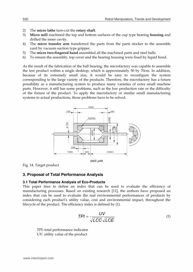
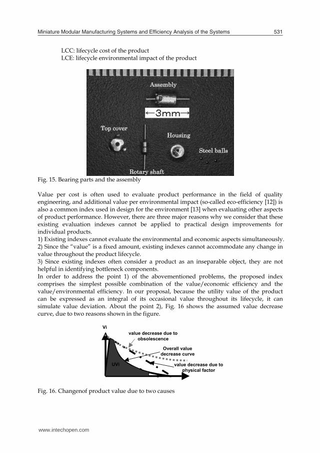
To prove that the microfactory is capable to machine and assemble a “product”, we selected an extra small ball bearing as the test product. Fig. 14 shows the target product, which is a ball bearing having 100 m rotary shaft diameter and 900 m outer diameter. The next Fig. 15 shows the results of the test production. The shape appears in the top of the photograph is the bearing assembly that 7 steel balls each side. Following procedure was the anufacturing process for the test product shown in Fig.15. 1) The micro press machine punched the top cover of the bearing.
www.intechopen.com
Robot Manipulators, Trends and Development530
2) The micro lathe turn-cut the rotary shaft. 3) Micro mill machined the top and bottom surfaces of the cup type bearing housing and
drilled the inner cavity. 4) The micro transfer arm transferred the parts from the parts stocker to the assemble
yard by vacuum suction type gripper. 5) The micro two-fingered hand assembled all the machined parts and steel balls. 6) To ensure the assembly, top cover and the bearing housing were fixed by liquid bond. As the result of the fabrication of the ball bearing, the microfactory was capable to assemble the test product within a single desktop, which is approximately 50 by 70cm. In addition, because of its extremely small size, it would be easy to reconfigure the system corresponding to the large variety of the products. Therefore, the microfactory has a future possibility as a manufacturing system to produce many varieties of extra small machine parts. However, it still has some problems, such as the low production rate or the difficulty of the fixture of the product. To apply the microfactory or similar small manufacturing systems to actual productions, those problems have to be solved.
unit m Fig. 14. Target product 3. Proposal of Total Performance Analysis
3.1 Total Performance Analysis of Eco-Products This paper tries to define an index that can be used to evaluate the efficiency of manufacturing processes. Based on existing research [11], the authors have proposed an index that can be used to evaluate the real environmental performances of products by considering each product’s utility value, cost and environmental impact, throughout the lifecycle of the product. The efficiency index is defined by (1).
LCELCC
UVTPI (1)
TPI: total performance indicator UV: utility value of the product
LCC: lifecycle cost of the product LCE: lifecycle environmental impact of the product
Fig. 15. Bearing parts and the assembly Value per cost is often used to evaluate product performance in the field of quality engineering, and additional value per environmental impact (so-called eco-efficiency [12]) is also a common index used in design for the environment [13] when evaluating other aspects of product performance. However, there are three major reasons why we consider that these existing evaluation indexes cannot be applied to practical design improvements for individual products. 1) Existing indexes cannot evaluate the environmental and economic aspects simultaneously. 2) Since the “value” is a fixed amount, existing indexes cannot accommodate any change in value throughout the product lifecycle. 3) Since existing indexes often consider a product as an inseparable object, they are not helpful in identifying bottleneck components. In order to address the point 1) of the abovementioned problems, the proposed index comprises the simplest possible combination of the value/economic efficiency and the value/environmental efficiency. In our proposal, because the utility value of the product can be expressed as an integral of its occasional value throughout its lifecycle, it can simulate value deviation. About the point 2), Fig. 16 shows the assumed value decrease curve, due to two reasons shown in the figure.
Vi
UVi
value decrease due to obsolescence
value decrease due to physical factor
Overall value decrease curve
Fig. 16. Changenof product value due to two causes
Assembly
Top cover
Rotary shaft
Housing
Steel balls
www.intechopen.com
Miniature Modular Manufacturing Systems and Eficiency Analysis of the Systems 531
2) The micro lathe turn-cut the rotary shaft. 3) Micro mill machined the top and bottom surfaces of the cup type bearing housing and
drilled the inner cavity. 4) The micro transfer arm transferred the parts from the parts stocker to the assemble
yard by vacuum suction type gripper. 5) The micro two-fingered hand assembled all the machined parts and steel balls. 6) To ensure the assembly, top cover and the bearing housing were fixed by liquid bond. As the result of the fabrication of the ball bearing, the microfactory was capable to assemble the test product within a single desktop, which is approximately 50 by 70cm. In addition, because of its extremely small size, it would be easy to reconfigure the system corresponding to the large variety of the products. Therefore, the microfactory has a future possibility as a manufacturing system to produce many varieties of extra small machine parts. However, it still has some problems, such as the low production rate or the difficulty of the fixture of the product. To apply the microfactory or similar small manufacturing systems to actual productions, those problems have to be solved.
unit m Fig. 14. Target product 3. Proposal of Total Performance Analysis
3.1 Total Performance Analysis of Eco-Products This paper tries to define an index that can be used to evaluate the efficiency of manufacturing processes. Based on existing research [11], the authors have proposed an index that can be used to evaluate the real environmental performances of products by considering each product’s utility value, cost and environmental impact, throughout the lifecycle of the product. The efficiency index is defined by (1).
LCELCC
UVTPI (1)
TPI: total performance indicator UV: utility value of the product
LCC: lifecycle cost of the product LCE: lifecycle environmental impact of the product
Fig. 15. Bearing parts and the assembly Value per cost is often used to evaluate product performance in the field of quality engineering, and additional value per environmental impact (so-called eco-efficiency [12]) is also a common index used in design for the environment [13] when evaluating other aspects of product performance. However, there are three major reasons why we consider that these existing evaluation indexes cannot be applied to practical design improvements for individual products. 1) Existing indexes cannot evaluate the environmental and economic aspects simultaneously. 2) Since the “value” is a fixed amount, existing indexes cannot accommodate any change in value throughout the product lifecycle. 3) Since existing indexes often consider a product as an inseparable object, they are not helpful in identifying bottleneck components. In order to address the point 1) of the abovementioned problems, the proposed index comprises the simplest possible combination of the value/economic efficiency and the value/environmental efficiency. In our proposal, because the utility value of the product can be expressed as an integral of its occasional value throughout its lifecycle, it can simulate value deviation. About the point 2), Fig. 16 shows the assumed value decrease curve, due to two reasons shown in the figure.
Vi
UVi
value decrease due to obsolescence
value decrease due to physical factor
Overall value decrease curve
Fig. 16. Changenof product value due to two causes
Assembly
Top cover
Rotary shaft
Housing
Steel balls
www.intechopen.com

Robot Manipulators, Trends and Development532
In addition to solve the point 3), when estimating the value in the equation, it is possible to allocate value to each component by using a QFD [14] approach. By this approach, it will be possible to calculate the defined TPI for each component. Then, by comparing the component TPI with that of the product average, we can answer which component is the bottleneck in enhancing the total environmental efficiency of the product. Therefore, our proposed TPI can provide an answer to the problems encountered with existing eco-performance indicators.
3.2 Extension to Manufacturing Systems The same approach can be used to evaluate the efficiencies of manufacturing systems. The extended calculation shown in (2) was proposed in the existing paper [15] and is used to evaluate system efficiency of the on-demand MEMS factory on the same basis. In this equation, the efficiency of the system is defined by the sum total of product values produced by the manufacturing system within a set period of time. Cost and environmental impact during the corresponding period are also considered. The cost and environmental impact involved in building the manufacturing system itself (the so-called initial cost and initial environmental impact) should be divided by the lifetime of the manufacturing system, and assigned to C and E in the equation.
dtCE
dtUVTPISystem
i
li
kii
Tt
t
mi
ii
Tt
t
0
0
1
0
0 (2)
T: period of estimation m: kinds of product k: number of the first process in the system l: number of the last process in the system
However, it is not easy to quantitatively calculate (2) when the system produces a range of different products because it is necessary to quantify all the values of these different products. However, when the product of the manufacturing system is always the same, the system TPI equation can be simplified to (3).
)
LE
E()CC
LC(
TpTPISystem
me
ELm
16001600
(3) Tp: throughput of the system (number of products produced in an hour) Cm: initial total cost of the machines (104 yen) CL: labor cost (104 yen/year) CE: energy cost (104 yen/year)
L: lifetime of the system (years) Ee: environmental impact caused by electricity use Em: environmental impact caused by the machines
Instead of using the utility value of a product, as defined in the original index, the throughput of the manufacturing system, “Tp”, can be adopted. By defining the throughput as the number of products fabricated within an hour, the total performance indicator of the manufacturing system can be calculated. “C” can be calculated by using the sum total of machine costs, labor costs and energy costs during the corresponding time period. However, other costs such as the cost of electricity (about 20 yen/kWh) are negligible. The cost of labor is assumed to be 5.0 (million yen) per person per year. For “E,” equivalent CO2 emission is the simplest index that can be used to evaluate the environmental impact. Therefore, “E” can be expressed by using the sum of CO2 emission values caused by power consumption and the materials used for machines and products. When considering electricity usage, 1kWh of electricity consumption is equivalent to 0.38kg-CO2.
4. Analysis of the Microfactory
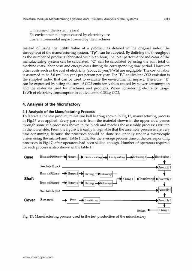
4.1 Analysis of the Manufacturing Process To fabricate the test product; miniature ball bearing shown in Fig.15, manufacturing process in Fig.17 was applied. Every part starts from the material shown in the upper side, passes through some sub-processes shown in the block and reaches the assembly processes written in the lower side. From the figure it is easily imaginable that the assembly processes are very time-consuming, because the processes should be done sequentially under a microscopic vision using the micro-hand. Table 1 indicates the average process time of the corresponding processes in Fig.17, after operators had been skilled enough. Number of operators required for each process is also shown in the table 1.
Steel balls (7 pcs.)
Transferring2 Releasing2
Releasing2TurningBrass rod (2mm) Fixture 2
TurningBrass rod (2mm) Fixture 2Gluing 1
Press Sheet metal Transferring 3
Assembly 1 Steel balls (7 pcs.)
Assembly 2
Brass rod (0.9mm) Fixture 1 Surface milling Cavity milling Releasing 1 Transferring 1
Assembly 3
Assembly 4
Gluing 2 Product
CaseCase
ShaftShaft
CoverCover
Fig. 17. Manufacturing process used in the test production of the microfactory
www.intechopen.com
Miniature Modular Manufacturing Systems and Eficiency Analysis of the Systems 533
In addition to solve the point 3), when estimating the value in the equation, it is possible to allocate value to each component by using a QFD [14] approach. By this approach, it will be possible to calculate the defined TPI for each component. Then, by comparing the component TPI with that of the product average, we can answer which component is the bottleneck in enhancing the total environmental efficiency of the product. Therefore, our proposed TPI can provide an answer to the problems encountered with existing eco-performance indicators.
3.2 Extension to Manufacturing Systems The same approach can be used to evaluate the efficiencies of manufacturing systems. The extended calculation shown in (2) was proposed in the existing paper [15] and is used to evaluate system efficiency of the on-demand MEMS factory on the same basis. In this equation, the efficiency of the system is defined by the sum total of product values produced by the manufacturing system within a set period of time. Cost and environmental impact during the corresponding period are also considered. The cost and environmental impact involved in building the manufacturing system itself (the so-called initial cost and initial environmental impact) should be divided by the lifetime of the manufacturing system, and assigned to C and E in the equation.
dtCE
dtUVTPISystem
i
li
kii
Tt
t
mi
ii
Tt
t
0
0
1
0
0 (2)
T: period of estimation m: kinds of product k: number of the first process in the system l: number of the last process in the system
However, it is not easy to quantitatively calculate (2) when the system produces a range of different products because it is necessary to quantify all the values of these different products. However, when the product of the manufacturing system is always the same, the system TPI equation can be simplified to (3).
)
LE
E()CC
LC(
TpTPISystem
me
ELm
16001600
(3) Tp: throughput of the system (number of products produced in an hour) Cm: initial total cost of the machines (104 yen) CL: labor cost (104 yen/year) CE: energy cost (104 yen/year)
L: lifetime of the system (years) Ee: environmental impact caused by electricity use Em: environmental impact caused by the machines
Instead of using the utility value of a product, as defined in the original index, the throughput of the manufacturing system, “Tp”, can be adopted. By defining the throughput as the number of products fabricated within an hour, the total performance indicator of the manufacturing system can be calculated. “C” can be calculated by using the sum total of machine costs, labor costs and energy costs during the corresponding time period. However, other costs such as the cost of electricity (about 20 yen/kWh) are negligible. The cost of labor is assumed to be 5.0 (million yen) per person per year. For “E,” equivalent CO2 emission is the simplest index that can be used to evaluate the environmental impact. Therefore, “E” can be expressed by using the sum of CO2 emission values caused by power consumption and the materials used for machines and products. When considering electricity usage, 1kWh of electricity consumption is equivalent to 0.38kg-CO2.
4. Analysis of the Microfactory
4.1 Analysis of the Manufacturing Process To fabricate the test product; miniature ball bearing shown in Fig.15, manufacturing process in Fig.17 was applied. Every part starts from the material shown in the upper side, passes through some sub-processes shown in the block and reaches the assembly processes written in the lower side. From the figure it is easily imaginable that the assembly processes are very time-consuming, because the processes should be done sequentially under a microscopic vision using the micro-hand. Table 1 indicates the average process time of the corresponding processes in Fig.17, after operators had been skilled enough. Number of operators required for each process is also shown in the table 1.
Steel balls (7 pcs.)
Transferring2 Releasing2
Releasing2TurningBrass rod (2mm) Fixture 2
TurningBrass rod (2mm) Fixture 2Gluing 1
Press Sheet metal Transferring 3
Assembly 1 Steel balls (7 pcs.)
Assembly 2
Brass rod (0.9mm) Fixture 1 Surface milling Cavity milling Releasing 1 Transferring 1
Assembly 3
Assembly 4
Gluing 2 Product
CaseCase
ShaftShaft
CoverCover
Steel balls (7 pcs.)
Transferring2 Releasing2
Releasing2TurningBrass rod (2mm) Fixture 2
TurningBrass rod (2mm) Fixture 2Gluing 1
Press Sheet metal Transferring 3
Assembly 1 Steel balls (7 pcs.)
Assembly 2
Brass rod (0.9mm) Fixture 1 Surface milling Cavity milling Releasing 1 Transferring 1
Assembly 3
Assembly 4
Gluing 2 Product
CaseCase
ShaftShaft
CoverCover
Fig. 17. Manufacturing process used in the test production of the microfactory
www.intechopen.com

Robot Manipulators, Trends and Development534
Process name Process time Number of operators Fixture 1 10 sec. 1 Fixture 2 5 sec. 1
Surface milling 1 min. 1 Cavity milling 2 min. 1
Turning 2 min. 1 Press 0.2 sec. 0
Releasing 1 10 sec. 1 Releasing 2 5 sec. 1
Transferring 1 1 sec. 0 Transferring 2 1 sec. 0 Transferring 3 1 sec. 0
Assembly 1 3 min. (per ball) 1 Assembly 2 3 min. 1 Assembly 3 3 min. (per ball) 1 Assembly 4 3 min. 1
Gluing 1 1 min. 1 Gluing 2 2 min. 1
Table 1. Required time for each process per unit
4.2 Total Performance Analysis of the Microfactory According to Fig.17 and Table 1, it is evident that the assembly operations done by the micro hand were the bottlenecks for the throughput. However, it is necessary to be aware that the flexibility of the process was assured by the function of the micro hand. Machine and labour costs are also important for manufacturing system designs. Table 2 shows the rough estimation for the cost of the machines used in the microfactory. And also the energy consumption of each machine is an important factor to consider system efficiencies. Table 3 shows the average power consumption of the machines during the operation. Both tables show that the micro hand was the most critical components for cost and energy, as well.
Machine Milling Turning Press Arm Hand Cost (millionYen) 0.7 1.2 2.0 3.0 5.0
Table 2. Machine costs
Machine Milling Turning Press Arm Hand Average power consumption (kw) 0.25 0.3 0.05 0.2 0.4
Table 3. Energy consumption
4.3 Configuration Design Based on the Analysis Analysis of the manufacturing process mentioned in the former section showed that the assembly processes performed by “micro-hand” is critical both for throughput and environmental impact. When the number of components or operators is not limited to be 1, a simple strategy to enhance system efficiency will be to increase the number of the “hands.” By assuming the annual operation time of the system is 1600 hours, the efficiency is calculated by aforementioned equation (3). By changing the system configuration,
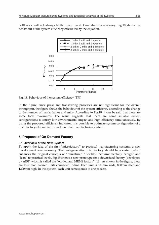
bottleneck will not always be the micro hand. Case study is necessary. Fig.18 shows the behaviour of the system efficiency calculated by the equation.
0.01
0.015
0.02
0.025
0.03
0.035
0.04
0 2 4 6 8 10 12
Number of hands
Effic
ienc
y
1 lathe, 1 mill and 1 operator1 lathe, 1 mill and 2 operators2 lathes, 2 mills and 2 operators2 lathes, 2 mills and 3 operators
Fig. 18. Behaviour of the system efficiency (TPI)
In the figure, since press and transferring processes are not significant for the overall throughput, the figure shows the behaviour of the system efficiency according to the change of the number of hands, lathes and mills. According to Fig.18, it can be said that there are some local maximums. The result suggests that there are some suitable system configurations to satisfy low environmental impact and high efficiency simultaneously. By using the proposed efficiency indicator, it is possible to optimize system configuration of a microfactory-like miniature and modular manufacturing system.
5. Proposal of On-Demand Factory
5.1 Overview of the New System
To apply the idea of the first “microfactory” to practical manufacturing systems, a new development was necessary. The next-generation microfactory should be a system which enhances the original concepts of “miniature,” “flexible,” “environmentally benign” and “lean” to practical levels. Fig.19 shows a new prototype for a downsized factory (developed by AIST) which is called the “on-demand MEMS factory” [16]. As shown in the figure, there are four modularized units connected in-line. Each unit is 500mm wide, 800mm deep and 1200mm high. In this system, each unit corresponds to one process.
www.intechopen.com
Miniature Modular Manufacturing Systems and Eficiency Analysis of the Systems 535
Process name Process time Number of operators Fixture 1 10 sec. 1 Fixture 2 5 sec. 1
Surface milling 1 min. 1 Cavity milling 2 min. 1
Turning 2 min. 1 Press 0.2 sec. 0
Releasing 1 10 sec. 1 Releasing 2 5 sec. 1
Transferring 1 1 sec. 0 Transferring 2 1 sec. 0 Transferring 3 1 sec. 0
Assembly 1 3 min. (per ball) 1 Assembly 2 3 min. 1 Assembly 3 3 min. (per ball) 1 Assembly 4 3 min. 1
Gluing 1 1 min. 1 Gluing 2 2 min. 1
Table 1. Required time for each process per unit
4.2 Total Performance Analysis of the Microfactory According to Fig.17 and Table 1, it is evident that the assembly operations done by the micro hand were the bottlenecks for the throughput. However, it is necessary to be aware that the flexibility of the process was assured by the function of the micro hand. Machine and labour costs are also important for manufacturing system designs. Table 2 shows the rough estimation for the cost of the machines used in the microfactory. And also the energy consumption of each machine is an important factor to consider system efficiencies. Table 3 shows the average power consumption of the machines during the operation. Both tables show that the micro hand was the most critical components for cost and energy, as well.
Machine Milling Turning Press Arm Hand Cost (millionYen) 0.7 1.2 2.0 3.0 5.0
Table 2. Machine costs
Machine Milling Turning Press Arm Hand Average power consumption (kw) 0.25 0.3 0.05 0.2 0.4
Table 3. Energy consumption
4.3 Configuration Design Based on the Analysis Analysis of the manufacturing process mentioned in the former section showed that the assembly processes performed by “micro-hand” is critical both for throughput and environmental impact. When the number of components or operators is not limited to be 1, a simple strategy to enhance system efficiency will be to increase the number of the “hands.” By assuming the annual operation time of the system is 1600 hours, the efficiency is calculated by aforementioned equation (3). By changing the system configuration,
bottleneck will not always be the micro hand. Case study is necessary. Fig.18 shows the behaviour of the system efficiency calculated by the equation.
0.01
0.015
0.02
0.025
0.03
0.035
0.04
0 2 4 6 8 10 12
Number of hands
Effic
ienc
y1 lathe, 1 mill and 1 operator1 lathe, 1 mill and 2 operators2 lathes, 2 mills and 2 operators2 lathes, 2 mills and 3 operators
Fig. 18. Behaviour of the system efficiency (TPI)
In the figure, since press and transferring processes are not significant for the overall throughput, the figure shows the behaviour of the system efficiency according to the change of the number of hands, lathes and mills. According to Fig.18, it can be said that there are some local maximums. The result suggests that there are some suitable system configurations to satisfy low environmental impact and high efficiency simultaneously. By using the proposed efficiency indicator, it is possible to optimize system configuration of a microfactory-like miniature and modular manufacturing system.
5. Proposal of On-Demand Factory
5.1 Overview of the New System
To apply the idea of the first “microfactory” to practical manufacturing systems, a new development was necessary. The next-generation microfactory should be a system which enhances the original concepts of “miniature,” “flexible,” “environmentally benign” and “lean” to practical levels. Fig.19 shows a new prototype for a downsized factory (developed by AIST) which is called the “on-demand MEMS factory” [16]. As shown in the figure, there are four modularized units connected in-line. Each unit is 500mm wide, 800mm deep and 1200mm high. In this system, each unit corresponds to one process.
www.intechopen.com
Robot Manipulators, Trends and Development536
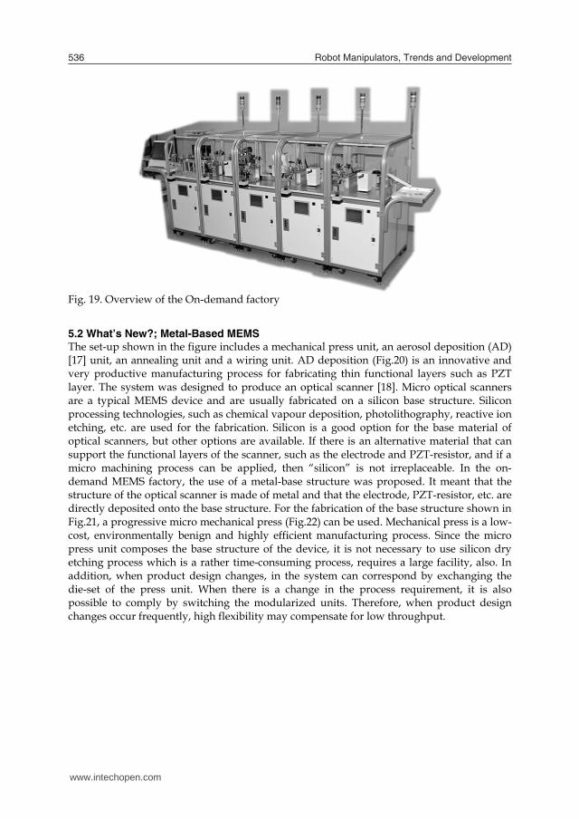
Fig. 19. Overview of the On-demand factory
5.2 What’s New?; Metal-Based MEMS
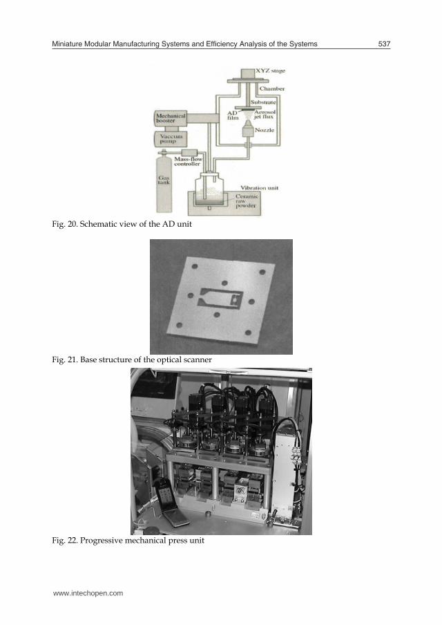
The set-up shown in the figure includes a mechanical press unit, an aerosol deposition (AD) [17] unit, an annealing unit and a wiring unit. AD deposition (Fig.20) is an innovative and very productive manufacturing process for fabricating thin functional layers such as PZT layer. The system was designed to produce an optical scanner [18]. Micro optical scanners are a typical MEMS device and are usually fabricated on a silicon base structure. Silicon processing technologies, such as chemical vapour deposition, photolithography, reactive ion etching, etc. are used for the fabrication. Silicon is a good option for the base material of optical scanners, but other options are available. If there is an alternative material that can support the functional layers of the scanner, such as the electrode and PZT-resistor, and if a micro machining process can be applied, then “silicon” is not irreplaceable. In the on-demand MEMS factory, the use of a metal-base structure was proposed. It meant that the structure of the optical scanner is made of metal and that the electrode, PZT-resistor, etc. are directly deposited onto the base structure. For the fabrication of the base structure shown in Fig.21, a progressive micro mechanical press (Fig.22) can be used. Mechanical press is a low-cost, environmentally benign and highly efficient manufacturing process. Since the micro press unit composes the base structure of the device, it is not necessary to use silicon dry etching process which is a rather time-consuming process, requires a large facility, also. In addition, when product design changes, in the system can correspond by exchanging the die-set of the press unit. When there is a change in the process requirement, it is also possible to comply by switching the modularized units. Therefore, when product design changes occur frequently, high flexibility may compensate for low throughput.
Fig. 20. Schematic view of the AD unit
Fig. 21. Base structure of the optical scanner
Fig. 22. Progressive mechanical press unit
www.intechopen.com
Miniature Modular Manufacturing Systems and Eficiency Analysis of the Systems 537
Fig. 19. Overview of the On-demand factory
5.2 What’s New?; Metal-Based MEMS
The set-up shown in the figure includes a mechanical press unit, an aerosol deposition (AD) [17] unit, an annealing unit and a wiring unit. AD deposition (Fig.20) is an innovative and very productive manufacturing process for fabricating thin functional layers such as PZT layer. The system was designed to produce an optical scanner [18]. Micro optical scanners are a typical MEMS device and are usually fabricated on a silicon base structure. Silicon processing technologies, such as chemical vapour deposition, photolithography, reactive ion etching, etc. are used for the fabrication. Silicon is a good option for the base material of optical scanners, but other options are available. If there is an alternative material that can support the functional layers of the scanner, such as the electrode and PZT-resistor, and if a micro machining process can be applied, then “silicon” is not irreplaceable. In the on-demand MEMS factory, the use of a metal-base structure was proposed. It meant that the structure of the optical scanner is made of metal and that the electrode, PZT-resistor, etc. are directly deposited onto the base structure. For the fabrication of the base structure shown in Fig.21, a progressive micro mechanical press (Fig.22) can be used. Mechanical press is a low-cost, environmentally benign and highly efficient manufacturing process. Since the micro press unit composes the base structure of the device, it is not necessary to use silicon dry etching process which is a rather time-consuming process, requires a large facility, also. In addition, when product design changes, in the system can correspond by exchanging the die-set of the press unit. When there is a change in the process requirement, it is also possible to comply by switching the modularized units. Therefore, when product design changes occur frequently, high flexibility may compensate for low throughput.
Fig. 20. Schematic view of the AD unit
Fig. 21. Base structure of the optical scanner
Fig. 22. Progressive mechanical press unit
www.intechopen.com
Robot Manipulators, Trends and Development538
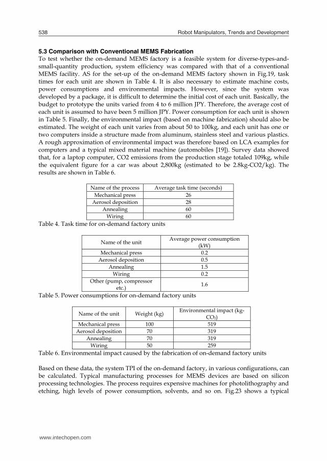
5.3 Comparison with Conventional MEMS Fabrication To test whether the on-demand MEMS factory is a feasible system for diverse-types-and-small-quantity production, system efficiency was compared with that of a conventional MEMS facility. AS for the set-up of the on-demand MEMS factory shown in Fig.19, task times for each unit are shown in Table 4. It is also necessary to estimate machine costs, power consumptions and environmental impacts. However, since the system was developed by a package, it is difficult to determine the initial cost of each unit. Basically, the budget to prototype the units varied from 4 to 6 million JPY. Therefore, the average cost of each unit is assumed to have been 5 million JPY. Power consumption for each unit is shown in Table 5. Finally, the environmental impact (based on machine fabrication) should also be estimated. The weight of each unit varies from about 50 to 100kg, and each unit has one or two computers inside a structure made from aluminum, stainless steel and various plastics. A rough approximation of environmental impact was therefore based on LCA examples for computers and a typical mixed material machine (automobiles [19]). Survey data showed that, for a laptop computer, CO2 emissions from the production stage totaled 109kg, while the equivalent figure for a car was about 2,800kg (estimated to be 2.8kg-CO2/kg). The results are shown in Table 6.
Name of the process Average task time (seconds) Mechanical press 26
Aerosol deposition 28 Annealing 60
Wiring 60 Table 4. Task time for on-demand factory units
Name of the unit Average power consumption (kW)
Mechanical press 0.2 Aerosol deposition 0.5
Annealing 1.5 Wiring 0.2
Other (pump, compressor etc.) 1.6
Table 5. Power consumptions for on-demand factory units
Name of the unit Weight (kg) Environmental impact (kg-CO2)
Mechanical press 100 519 Aerosol deposition 70 319
Annealing 70 319 Wiring 50 259
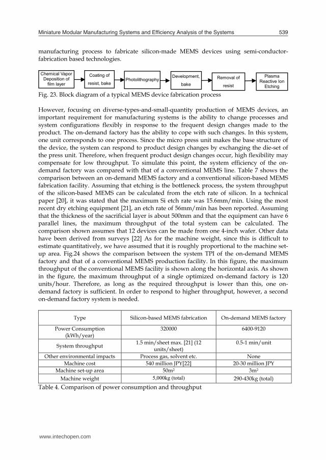
Table 6. Environmental impact caused by the fabrication of on-demand factory units Based on these data, the system TPI of the on-demand factory, in various configurations, can be calculated. Typical manufacturing processes for MEMS devices are based on silicon processing technologies. The process requires expensive machines for photolithography and etching, high levels of power consumption, solvents, and so on. Fig.23 shows a typical
manufacturing process to fabricate silicon-made MEMS devices using semi-conductor-fabrication based technologies. Chemical Vapor
Deposition of film layer
Coating of
resist, bake Photolithography
Development,
bake Removal of
resist
Plasma Reactive Ion
Etching Fig. 23. Block diagram of a typical MEMS device fabrication process However, focusing on diverse-types-and-small-quantity production of MEMS devices, an important requirement for manufacturing systems is the ability to change processes and system configurations flexibly in response to the frequent design changes made to the product. The on-demand factory has the ability to cope with such changes. In this system, one unit corresponds to one process. Since the micro press unit makes the base structure of the device, the system can respond to product design changes by exchanging the die-set of the press unit. Therefore, when frequent product design changes occur, high flexibility may compensate for low throughput. To simulate this point, the system efficiency of the on-demand factory was compared with that of a conventional MEMS line. Table 7 shows the comparison between an on-demand MEMS factory and a conventional silicon-based MEMS fabrication facility. Assuming that etching is the bottleneck process, the system throughput of the silicon-based MEMS can be calculated from the etch rate of silicon. In a technical paper [20], it was stated that the maximum Si etch rate was 15.6mm/min. Using the most recent dry etching equipment [21], an etch rate of 56mm/min has been reported. Assuming that the thickness of the sacrificial layer is about 500mm and that the equipment can have 6 parallel lines, the maximum throughput of the total system can be calculated. The comparison shown assumes that 12 devices can be made from one 4-inch wafer. Other data have been derived from surveys [22] As for the machine weight, since this is difficult to estimate quantitatively, we have assumed that it is roughly proportional to the machine set-up area. Fig.24 shows the comparison between the system TPI of the on-demand MEMS factory and that of a conventional MEMS production facility. In this figure, the maximum throughput of the conventional MEMS facility is shown along the horizontal axis. As shown in the figure, the maximum throughput of a single optimized on-demand factory is 120 units/hour. Therefore, as long as the required throughput is lower than this, one on-demand factory is sufficient. In order to respond to higher throughput, however, a second on-demand factory system is needed.
Type Silicon-based MEMS fabrication On-demand MEMS factory
Power Consumption (kWh/year)
320000 6400-9120
System throughput 1.5 min/sheet max. [21] (12 units/sheet)
0.5-1 min/unit
Other environmental impacts Process gas, solvent etc. None Machine cost 540 million JPY[22] 20-30 million JPY
Machine set-up area 50m2 3m2 Machine weight 5,000kg (total) 290-430kg (total)
Table 4. Comparison of power consumption and throughput
www.intechopen.com
Miniature Modular Manufacturing Systems and Eficiency Analysis of the Systems 539
5.3 Comparison with Conventional MEMS Fabrication To test whether the on-demand MEMS factory is a feasible system for diverse-types-and-small-quantity production, system efficiency was compared with that of a conventional MEMS facility. AS for the set-up of the on-demand MEMS factory shown in Fig.19, task times for each unit are shown in Table 4. It is also necessary to estimate machine costs, power consumptions and environmental impacts. However, since the system was developed by a package, it is difficult to determine the initial cost of each unit. Basically, the budget to prototype the units varied from 4 to 6 million JPY. Therefore, the average cost of each unit is assumed to have been 5 million JPY. Power consumption for each unit is shown in Table 5. Finally, the environmental impact (based on machine fabrication) should also be estimated. The weight of each unit varies from about 50 to 100kg, and each unit has one or two computers inside a structure made from aluminum, stainless steel and various plastics. A rough approximation of environmental impact was therefore based on LCA examples for computers and a typical mixed material machine (automobiles [19]). Survey data showed that, for a laptop computer, CO2 emissions from the production stage totaled 109kg, while the equivalent figure for a car was about 2,800kg (estimated to be 2.8kg-CO2/kg). The results are shown in Table 6.
Name of the process Average task time (seconds) Mechanical press 26
Aerosol deposition 28 Annealing 60
Wiring 60 Table 4. Task time for on-demand factory units
Name of the unit Average power consumption (kW)
Mechanical press 0.2 Aerosol deposition 0.5
Annealing 1.5 Wiring 0.2
Other (pump, compressor etc.) 1.6
Table 5. Power consumptions for on-demand factory units
Name of the unit Weight (kg) Environmental impact (kg-CO2)
Mechanical press 100 519 Aerosol deposition 70 319
Annealing 70 319 Wiring 50 259
Table 6. Environmental impact caused by the fabrication of on-demand factory units Based on these data, the system TPI of the on-demand factory, in various configurations, can be calculated. Typical manufacturing processes for MEMS devices are based on silicon processing technologies. The process requires expensive machines for photolithography and etching, high levels of power consumption, solvents, and so on. Fig.23 shows a typical
manufacturing process to fabricate silicon-made MEMS devices using semi-conductor-fabrication based technologies. Chemical Vapor
Deposition of film layer
Coating of
resist, bake Photolithography
Development,
bake Removal of
resist
Plasma Reactive Ion
Etching Fig. 23. Block diagram of a typical MEMS device fabrication process However, focusing on diverse-types-and-small-quantity production of MEMS devices, an important requirement for manufacturing systems is the ability to change processes and system configurations flexibly in response to the frequent design changes made to the product. The on-demand factory has the ability to cope with such changes. In this system, one unit corresponds to one process. Since the micro press unit makes the base structure of the device, the system can respond to product design changes by exchanging the die-set of the press unit. Therefore, when frequent product design changes occur, high flexibility may compensate for low throughput. To simulate this point, the system efficiency of the on-demand factory was compared with that of a conventional MEMS line. Table 7 shows the comparison between an on-demand MEMS factory and a conventional silicon-based MEMS fabrication facility. Assuming that etching is the bottleneck process, the system throughput of the silicon-based MEMS can be calculated from the etch rate of silicon. In a technical paper [20], it was stated that the maximum Si etch rate was 15.6mm/min. Using the most recent dry etching equipment [21], an etch rate of 56mm/min has been reported. Assuming that the thickness of the sacrificial layer is about 500mm and that the equipment can have 6 parallel lines, the maximum throughput of the total system can be calculated. The comparison shown assumes that 12 devices can be made from one 4-inch wafer. Other data have been derived from surveys [22] As for the machine weight, since this is difficult to estimate quantitatively, we have assumed that it is roughly proportional to the machine set-up area. Fig.24 shows the comparison between the system TPI of the on-demand MEMS factory and that of a conventional MEMS production facility. In this figure, the maximum throughput of the conventional MEMS facility is shown along the horizontal axis. As shown in the figure, the maximum throughput of a single optimized on-demand factory is 120 units/hour. Therefore, as long as the required throughput is lower than this, one on-demand factory is sufficient. In order to respond to higher throughput, however, a second on-demand factory system is needed.
Type Silicon-based MEMS fabrication On-demand MEMS factory
Power Consumption (kWh/year)
320000 6400-9120
System throughput 1.5 min/sheet max. [21] (12 units/sheet)
0.5-1 min/unit
Other environmental impacts Process gas, solvent etc. None Machine cost 540 million JPY[22] 20-30 million JPY
Machine set-up area 50m2 3m2 Machine weight 5,000kg (total) 290-430kg (total)
Table 4. Comparison of power consumption and throughput
www.intechopen.com

Robot Manipulators, Trends and Development540
0
30
60
90
120
150
0 180 360 540 720Throughput (units/hour )
Sys
tem
TP
IConventional MEMS fabrication(5 years)Conventional MEMS fabrication(1 year)On-demand factory (Original, 5years)On-demand factory (Original, 1year)On-demand factory (Optimized, 5years)On-demand factory (Optimized, 1year)
Fig. 24. Comparison of system efficiency(TPI)
When the required throughput is just over 120 units/hour, the TPI of two on-demand factory systems is almost half the maximum TPI of the single system, and when the second system approaches its full operation stage, the throughput of the total system approaches 240 units/hour and the TPI of the total system reaches its maximum. As shown in the figure, it is evident that the system TPI of the on-demand factory is always higher than that of the conventional MEMS facility. Of course, this is only a simulation and it contains many assumptions. For example, it is not clear whether the maximum throughput can be always achieved by the on-demand MEMS factory, and it is not evident whether the value of a silicon-based MEMS device and a metal-based MEMS device is the same. Even though there are still some problems to be resolved, the comparison indicates that the newly developed on-demand MEMS factory has a bright future as a practical diverse-types-and-small-quantity production system of MEMS devices.
6. Summary
In this chapter, the microfactory developed by AIST in 1999 was introduced. The prototyped desktop microfactory showed the capability as a space-saving and energy-saving manufacturing system for small products. The portable microfactory demonstrated a concept of a future on-site manufacturing. The capability was proved through the test production. The development team explained that the advantages of microfactory-like miniature manufacturing systems are low environmental impact and high production flexibility. However, the actual effect has not been estimated quantitatively until now. In order to evaluate system efficiencies of those manufacturing systems and to prove that microfactory-like systems are reasonable options for diverse-types-and-small-volume
production, a simple index to evaluate the system efficiency of manufacturing systems was proposed, based on the Total Performance Indicator proposed by the authors group. The indicator can evaluate the balance of functionality, cost and environmental impact of various products, considering value change throughout the product lifecycle. This time, the same idea was applied to manufacturing system evaluation. Using the modified equation, system efficiency of the first microfactory was calculated. As the results of the analysis, it was suggested that it would be able to re-design system configuration, by using the evaluation result. It led us to conclude that the proposed efficiency index is suitable for a modular manufacturing system like the microfactory. However, the actual efficiency of the microfactory was not high comparing to a typical mass production system for the same product. The fact suggested that a newer development would be necessary. Then, a new concept of a miniature manufacturing system called on-demand MEMS factory was introduced. And the same index to evaluate the system efficiency of a downsized manufacturing system was applied by considering system throughput, machine costs, labor cost, and CO2 emission caused by machine material and electricity. The evaluation result was compared with a rough estimation of the efficiency of a conventional MEMS fabrication facility based on semi-conductor fabrication technologies. The comparison indicated that the efficiency index of the on-demand MEMS factory was basically higher than that of the conventional facility. Especially when the required throughput is low, the advantage of the on-demand MEMS factory was evident. Thus, it was concluded that the concept is suitable for diverse-types-and-small-quantity productions of MEMS devices. In addition, manufacturing processes implemented in the on-demand MEMS factory such as “aerosol deposition” and “progressive mechanical press” were highly productive and environmentally benign processes comparing to conventional semiconductor fabrication technologies. Therefore, it was suggested that by applying new manufacturing technologies, an alternative material and a well-designed system, MEMS fabrication can be greatly improved. As the future work, more precise comparisons with conventional manufacturing systems are required in order to prove the effectiveness of the concept. And quantification of product value when the design of the product is changed is also necessary. About the evaluation method, modification of efficiency index to consider production flexibility along with frequent changes of product design will become necessary to estimate the real advantage of modularized manufacturing systems. And comparison with other integrated eco-efficiency evaluation methods will be necessary to insist the advantages of the proposing method. 7. References
[1] T. Kitahara, Y. Ishikawa, K. Terada, N. Nakajima, and K. Furuta, Development of Micro-lathe, Journal of Mechanical Engineering Laboratory, Vol. 50, No. 5, pp. 117-123, 1996.
[2] N. Kawahara, T. Suto, T. Hirano, Y. Ishikawa, N. Ooyama and T. Ataka, Microfactories; New Applications of micro machine technology to the manufacture of small products, Microsystem Technologies, 3-2, pp37-41, 1997.
[3] R. Hollis and A. Quaid, An architecture for agile assembly, Proceedings of ASPE 10th Annual Meeting, 1995.
www.intechopen.com
Miniature Modular Manufacturing Systems and Eficiency Analysis of the Systems 541
0
30
60
90
120
150
0 180 360 540 720Throughput (units/hour )
Sys
tem
TP
I
Conventional MEMS fabrication(5 years)Conventional MEMS fabrication(1 year)On-demand factory (Original, 5years)On-demand factory (Original, 1year)On-demand factory (Optimized, 5years)On-demand factory (Optimized, 1year)
Fig. 24. Comparison of system efficiency(TPI)
When the required throughput is just over 120 units/hour, the TPI of two on-demand factory systems is almost half the maximum TPI of the single system, and when the second system approaches its full operation stage, the throughput of the total system approaches 240 units/hour and the TPI of the total system reaches its maximum. As shown in the figure, it is evident that the system TPI of the on-demand factory is always higher than that of the conventional MEMS facility. Of course, this is only a simulation and it contains many assumptions. For example, it is not clear whether the maximum throughput can be always achieved by the on-demand MEMS factory, and it is not evident whether the value of a silicon-based MEMS device and a metal-based MEMS device is the same. Even though there are still some problems to be resolved, the comparison indicates that the newly developed on-demand MEMS factory has a bright future as a practical diverse-types-and-small-quantity production system of MEMS devices.
6. Summary
In this chapter, the microfactory developed by AIST in 1999 was introduced. The prototyped desktop microfactory showed the capability as a space-saving and energy-saving manufacturing system for small products. The portable microfactory demonstrated a concept of a future on-site manufacturing. The capability was proved through the test production. The development team explained that the advantages of microfactory-like miniature manufacturing systems are low environmental impact and high production flexibility. However, the actual effect has not been estimated quantitatively until now. In order to evaluate system efficiencies of those manufacturing systems and to prove that microfactory-like systems are reasonable options for diverse-types-and-small-volume
production, a simple index to evaluate the system efficiency of manufacturing systems was proposed, based on the Total Performance Indicator proposed by the authors group. The indicator can evaluate the balance of functionality, cost and environmental impact of various products, considering value change throughout the product lifecycle. This time, the same idea was applied to manufacturing system evaluation. Using the modified equation, system efficiency of the first microfactory was calculated. As the results of the analysis, it was suggested that it would be able to re-design system configuration, by using the evaluation result. It led us to conclude that the proposed efficiency index is suitable for a modular manufacturing system like the microfactory. However, the actual efficiency of the microfactory was not high comparing to a typical mass production system for the same product. The fact suggested that a newer development would be necessary. Then, a new concept of a miniature manufacturing system called on-demand MEMS factory was introduced. And the same index to evaluate the system efficiency of a downsized manufacturing system was applied by considering system throughput, machine costs, labor cost, and CO2 emission caused by machine material and electricity. The evaluation result was compared with a rough estimation of the efficiency of a conventional MEMS fabrication facility based on semi-conductor fabrication technologies. The comparison indicated that the efficiency index of the on-demand MEMS factory was basically higher than that of the conventional facility. Especially when the required throughput is low, the advantage of the on-demand MEMS factory was evident. Thus, it was concluded that the concept is suitable for diverse-types-and-small-quantity productions of MEMS devices. In addition, manufacturing processes implemented in the on-demand MEMS factory such as “aerosol deposition” and “progressive mechanical press” were highly productive and environmentally benign processes comparing to conventional semiconductor fabrication technologies. Therefore, it was suggested that by applying new manufacturing technologies, an alternative material and a well-designed system, MEMS fabrication can be greatly improved. As the future work, more precise comparisons with conventional manufacturing systems are required in order to prove the effectiveness of the concept. And quantification of product value when the design of the product is changed is also necessary. About the evaluation method, modification of efficiency index to consider production flexibility along with frequent changes of product design will become necessary to estimate the real advantage of modularized manufacturing systems. And comparison with other integrated eco-efficiency evaluation methods will be necessary to insist the advantages of the proposing method. 7. References
[1] T. Kitahara, Y. Ishikawa, K. Terada, N. Nakajima, and K. Furuta, Development of Micro-lathe, Journal of Mechanical Engineering Laboratory, Vol. 50, No. 5, pp. 117-123, 1996.
[2] N. Kawahara, T. Suto, T. Hirano, Y. Ishikawa, N. Ooyama and T. Ataka, Microfactories; New Applications of micro machine technology to the manufacture of small products, Microsystem Technologies, 3-2, pp37-41, 1997.
[3] R. Hollis and A. Quaid, An architecture for agile assembly, Proceedings of ASPE 10th Annual Meeting, 1995.
www.intechopen.com
Robot Manipulators, Trends and Development542
[4] T. Gaugel et. al., Advanced Modular Production Concept for Miniaturized Products, Proceeding of 2nd International workshop on Microfactories, Fribourg, Switzerland, pp. 35-38, 2000.10.
[5] K. Furuta, Experimental Processing and Assembling System (Microfactory), Proceedings of the 5th International Micromachine Symposium, pp. 173-177, 1999.
[6] D. N. Reshtov and V. T. Portman, Accuracy of Machine Tools, ASME Press, New York, 1988. [7] G. Taguchi and S. Konishi, Quality Engineering Series Vol.1-4, ASI Press, 1994. [8] N. Mishima and K. Ishii, Robustness Evaluation of a Miniaturized Machine Tool, Proceedings
of ASME/DETC99, Las Vegas, NV, DETC/DAC-8579, 1999.9. [9] T. Tanikawa, H. Maekawa, K. Kaneko and M. Tanaka, Micro Arm for Transfer and Micro
Hand for Assembly on Machining Microfactory, Proceedings of 2nd Int’l Workshop on Microfactories, pp. 155-158, 2000.10.
[10] T. Tanikawa and T. Arai, Development of a Micro-Manipulation System Having a Two-Fingered Micro-Hand, IEEE Transaction on robotics and Automation, Vol. 15, No. 1, pp.152-162, 1999.
[11] S. Kondoh, K. Masui, M. Hattori, N. Mishima and M. Matsumoto, “Total Performance Analysis of Product Life Cycle Considering the Deterioration and Obsolescence of Product Value,” Proc. of CARE INNOVATION 2006, Vienna, Austria, 2006, 2.10.1.
[12] Y. Kudoh, K. Tahara and A. Inaba, Environmental Efficiency of Passenger Vehicles: How Can the Value of a Vehicle be Determined?, Proc. of 7th International Conference on Ecobalance, Tsukuba, Japan, 2006, B3-7.
[13] M. Ernzer, M. Lindahl, K. Masui and T. Sakao, An International Study on Utilizing of Design Environmental Methods (DfE) –a pre-study-, Proc. of Third International Symposium on Environmentally Conscious Design and Inverse Manufacturing, IEEE Computer Society, 2003, pp.124-131.
[14] K. Akao, Quality Function Deployment, Productivity Process, Cambridge, MA, 1990. [15] N. Mishima, S. Kondoh and K. Masui, Proposal of An Efficiency Evaluation Index for Micro
Manufacturing Systems, Proc. of IEEE ICMA 2007, Harbin, China, Aug. 2007, pp.51-56. [16] S. Nakano, K. Ashida, J.Park and J.Akedo, On-demand MEMS factory system consists of
metal forming and aerosol deposition, Proc. of the 24th International Japan-Korea Seminar on Ceramics, pp.735-738.
[17] J.Akedo and M.Lebedev, Japan Journal of Applied Physics, 38, 9B (1990), 5397-5401. [18] Y.Takahashi, Y. Takeuchi and H. Fujita, Micromachined Optical Scanner for Optical
Measurement System, IEEJ Trans. SM, Vol.123, No.10, 2003, pp403-408. (In Japanese) [19] Japan Automobile Manufacturers Association Inc., Web page of Japan Automobile
Manufacturers Association, http://www.jama.or.jp/lib/jamagazine/199806/02.html (In Japanese)
[20] S. Frederico et. al., Silicon Layer Dry Etching for free-standing RF MEMS architectures, Proc. Of IEEE 16th Annual International Conference on MEMS, Kyoto, Japan, Jan. 2003, pp570-573.
[21]http://industrial.panasonic.com/ww/products_e/product_cat2/ACAH000_e/AC AH000_e/select_e.html
[22] TRONIC'S Microsystems - Micro Electro Mechanical Systems (MEMS) Facility, France, News, views and contacts from the semiconductor industry, http://www.semiconductor-technology.com/projects/tronic/
www.intechopen.com

Robot Manipulators Trends and DevelopmentEdited by Agustin Jimenez and Basil M Al Hadithi
ISBN 978-953-307-073-5Hard cover, 666 pagesPublisher InTechPublished online 01, March, 2010Published in print edition March, 2010
InTech EuropeUniversity Campus STeP Ri Slavka Krautzeka 83/A 51000 Rijeka, Croatia Phone: +385 (51) 770 447 Fax: +385 (51) 686 166www.intechopen.com
InTech ChinaUnit 405, Office Block, Hotel Equatorial Shanghai No.65, Yan An Road (West), Shanghai, 200040, China
Phone: +86-21-62489820 Fax: +86-21-62489821
This book presents the most recent research advances in robot manipulators. It offers a complete survey tothe kinematic and dynamic modelling, simulation, computer vision, software engineering, optimization anddesign of control algorithms applied for robotic systems. It is devoted for a large scale of applications, such asmanufacturing, manipulation, medicine and automation. Several control methods are included such as optimal,adaptive, robust, force, fuzzy and neural network control strategies. The trajectory planning is discussed indetails for point-to-point and path motions control. The results in obtained in this book are expected to be ofgreat interest for researchers, engineers, scientists and students, in engineering studies and industrial sectorsrelated to robot modelling, design, control, and application. The book also details theoretical, mathematicaland practical requirements for mathematicians and control engineers. It surveys recent techniques inmodelling, computer simulation and implementation of advanced and intelligent controllers.
How to referenceIn order to correctly reference this scholarly work, feel free to copy and paste the following:
Nozomu Mishima, Kondoh Shinsuke, Kiwamu Ashida and Shizuka Nakano (2010). Miniature ModularManufacturing Systems and Efficiency Analysis of the Systems, Robot Manipulators Trends and Development,Agustin Jimenez and Basil M Al Hadithi (Ed.), ISBN: 978-953-307-073-5, InTech, Available from:http://www.intechopen.com/books/robot-manipulators-trends-and-development/miniature-modular-manufacturing-systems-and-efficiency-analysis-of-the-systems

© 2010 The Author(s). Licensee IntechOpen. This chapter is distributedunder the terms of the Creative Commons Attribution-NonCommercial-ShareAlike-3.0 License, which permits use, distribution and reproduction fornon-commercial purposes, provided the original is properly cited andderivative works building on this content are distributed under the samelicense.