Embed Size (px)
Citation preview
MINIATURECIRCUIT BREAKER
www.alfanar.com

Contents
alfanar miniature circut breaker product features
Design Features 5
a - Aesthetics 5
b - alfanar patented design 5
Safety Features 6
a - Sealable Handle 6
b - True Contact Indication 6
c - IP20 Protection 6
d - Phase Barrier 6
e - Anti Single Phasing 7
f - Energy Class 3 7
g - Contact Separation 7
Reliability Features 8
a - Rigid Multi-Pole Coupling 8
b - Conforms to Major International Standards 8
c - Reliable Termination 8
d - Ready for Connection 8
Performance Features 9
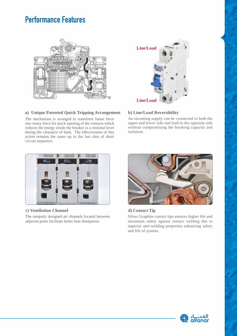
a - Unique Patented Quick Tripping Arrangement 9
b - Line / Load Reversibility 9
c - Ventilation Channel 9
d - Contact Tip 9
Installation Features 10
a - Ergonomics: Better Grip 10
b - Multiple Cable Connection 10
c - Suitable for Multiple Tools 10
d - Multiple Termination 10
e - Terminal Shutter 10
f - Ease of Mounting 10
Environment Features 11
Performance and Technical Specification 12
General Characteristics 13
Dimensions 19
Installation and Ease of Use 20
Ordering Data 21
4
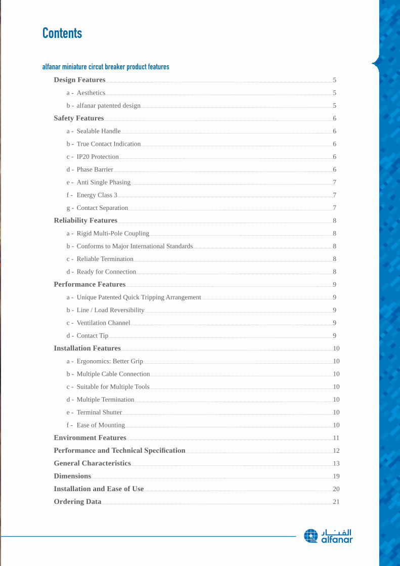
Design
Safety
Reliability
Performance
Installation
MINIATURE CIRCUIT BREAKER Product Features
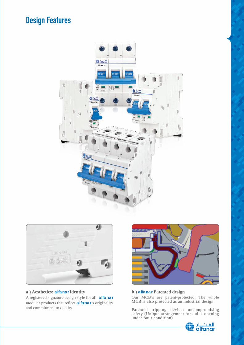
A registered signature design style for all alfanar modular products that reflect alfanar’s originality and commitment to quality.
Our MCB’s are patent-protected. The whole MCB is also protected as an industrial design.
Patented tripping device: uncompromising safety (Unique arrangement for quick opening under fault condition)
a ) Aesthetics: alfanar identity b ) alfanar Patented design
Design Features
6
Safety Features
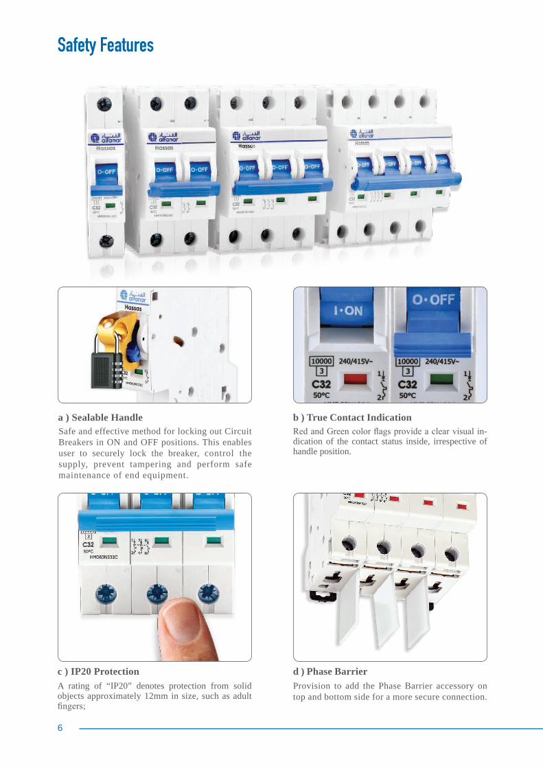
Provision to add the Phase Barrier accessory on top and bottom side for a more secure connection.
d ) Phase Barrier
a ) Sealable Handle Safe and effective method for locking out Circuit Breakers in ON and OFF positions. This enables user to securely lock the breaker, control the supply, prevent tampering and perform safe maintenance of end equipment.
c ) IP20 Protection A rating of “IP20” denotes protection from solid objects approximately 12mm in size, such as adult fingers;
b ) True Contact IndicationRed and Green color flags provide a clear visual in-dication of the contact status inside, irrespective of handle position.
e ) Anti Single Phasing For Multi-Pole breakers, removal of the handle connector is impossible.
Even in the absence of the handle connector, it is not possible to turn the multi-pole MCB “ON”.
This prevents closing even one pole of the Multi-Pole breaker in response to the overcurrent fault in any of poles.
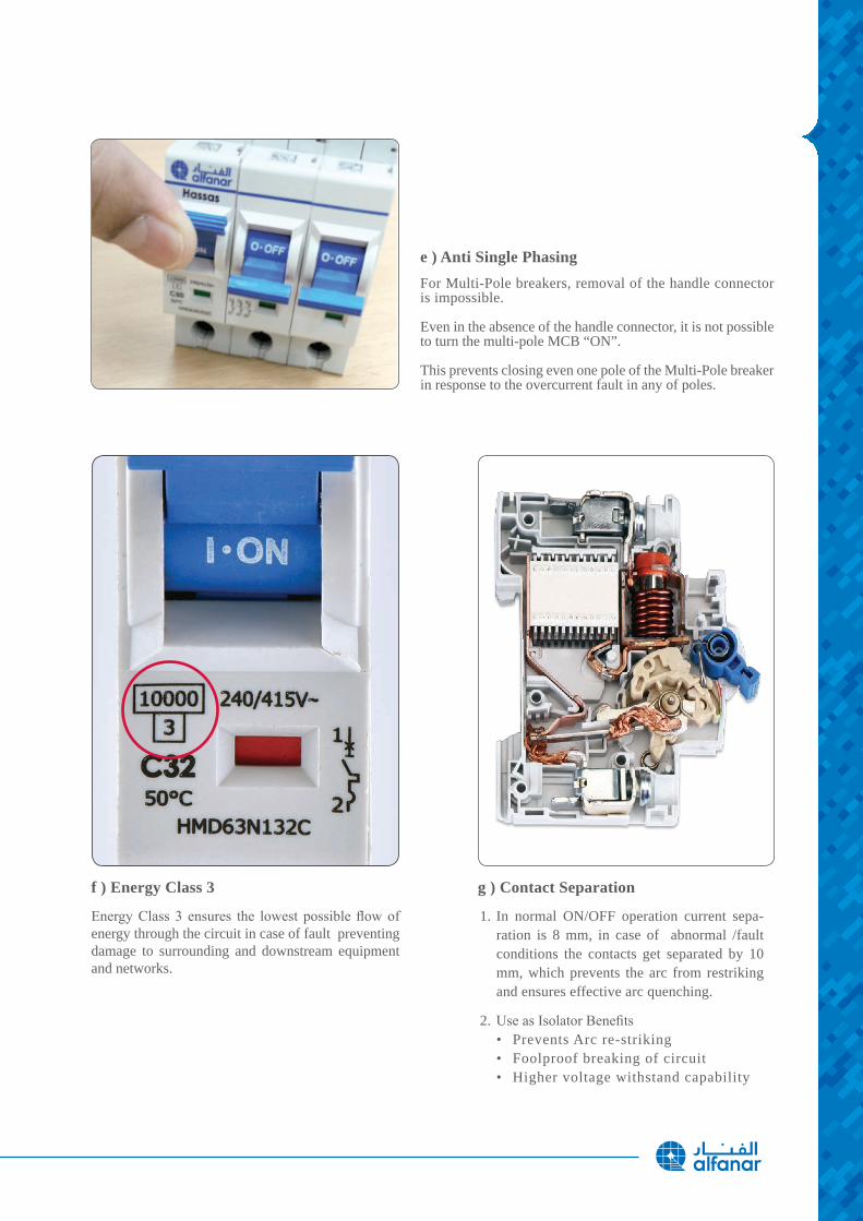
f ) Energy Class 3
Energy Class 3 ensures the lowest possible flow of energy through the circuit in case of fault preventing damage to surrounding and downstream equipment and networks.
g ) Contact Separation
1. In normal ON/OFF operation current sepa-ration is 8 mm, in case of abnormal /fault conditions the contacts get separated by 10 mm, which prevents the arc from restriking and ensures effective arc quenching.
2. Use as Isolator Benefits• Prevents Arc re-striking• Foolproof breaking of circuit • Higher voltage withstand capability
8
Reliability Features
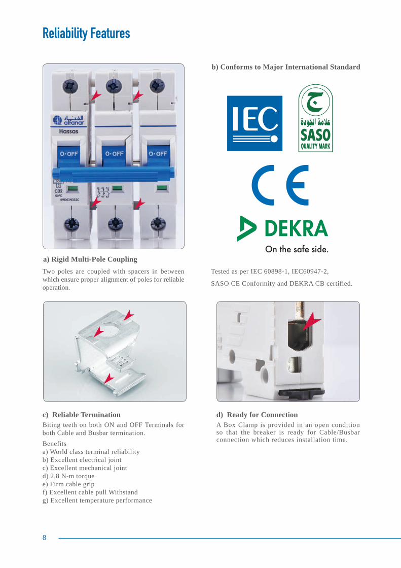
Two poles are coupled with spacers in between which ensure proper alignment of poles for reliable operation.
a) Rigid Multi-Pole Coupling
d) Ready for ConnectionA Box Clamp is provided in an open condition so that the breaker is ready for Cable/Busbar connection which reduces installation time.
Biting teeth on both ON and OFF Terminals for both Cable and Busbar termination.Benefits a) World class terminal reliability b) Excellent electrical joint c) Excellent mechanical joint d) 2.8 N-m torquee) Firm cable gripf) Excellent cable pull Withstand g) Excellent temperature performance
c) Reliable Termination
b) Conforms to Major International Standard
Tested as per IEC 60898-1, IEC60947-2,
SASO CE Conformity and DEKRA CB certified.
Performance Features
The uniquely designed air channels located between adjacent poles facilitate better heat dissipation.
Silver Graphite contact tips ensures higher life and maximum safety against contact welding due to superior anti-welding properties enhancing safety and life of system.
The mechanism is arranged to transform linear force into rotary force for quick opening of the contacts which reduces the energy inside the breaker to a minimal level during the clearance of fault. The effectiveness of this action remains the same up to the last shot of short circuit sequence.
a) Unique Patented Quick Tripping Arrangement
c) Ventilation Channel d) Contact Tip
An incoming supply can be connected to both the upper and lower side and load to the opposite side without compromising the breaking capacity and isolation.
b) Line/Load Reversibility
Line/Load
Line/Load
10
Installation Features
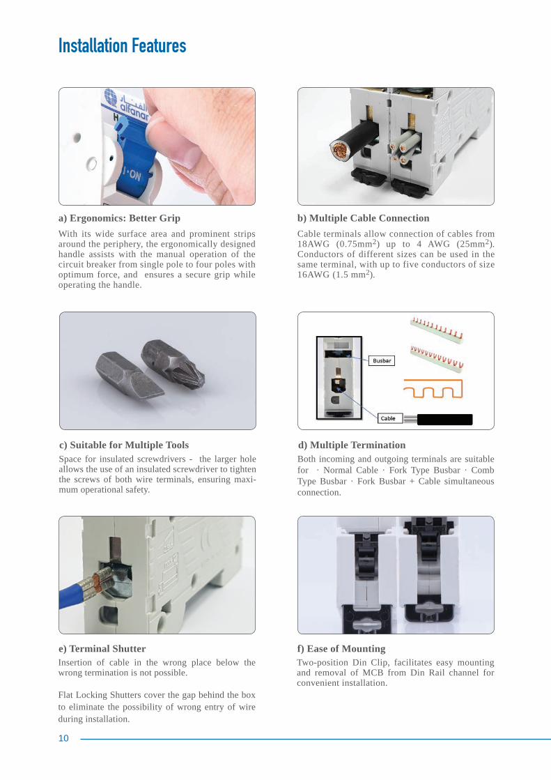
Space for insulated screwdrivers - the larger hole allows the use of an insulated screwdriver to tighten the screws of both wire terminals, ensuring maxi-mum operational safety.
Insertion of cable in the wrong place below the wrong termination is not possible.
Flat Locking Shutters cover the gap behind the box to eliminate the possibility of wrong entry of wire during installation.
Two-position Din Clip, facilitates easy mounting and removal of MCB from Din Rail channel for convenient installation.
Cable terminals allow connection of cables from 18AWG (0.75mm2) up to 4 AWG (25mm2). Conductors of different sizes can be used in the same terminal, with up to five conductors of size 16AWG (1.5 mm2).
Both incoming and outgoing terminals are suitable for · Normal Cable · Fork Type Busbar · Comb Type Busbar · Fork Busbar + Cable simultaneous connection.
b) Multiple Cable Connection
c) Suitable for Multiple Tools
e) Terminal Shutter f) Ease of Mounting
d) Multiple Termination
a) Ergonomics: Better GripWith its wide surface area and prominent strips around the periphery, the ergonomically designed handle assists with the manual operation of the circuit breaker from single pole to four poles with optimum force, and ensures a secure grip while operating the handle.
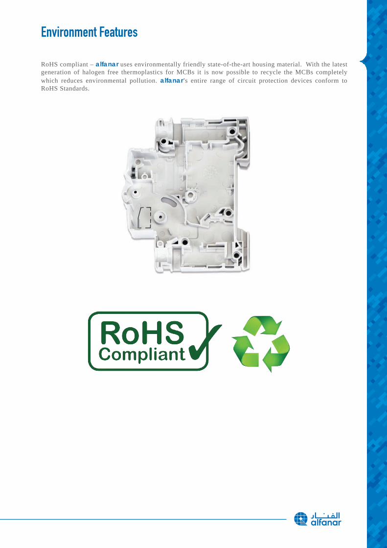
Environment Features
RoHS compliant – alfanar uses environmentally friendly state-of-the-art housing material. With the latest generation of halogen free thermoplastics for MCBs it is now possible to recycle the MCBs completely which reduces environmental pollution. alfanar’s entire range of circuit protection devices conform to RoHS Standards.
12
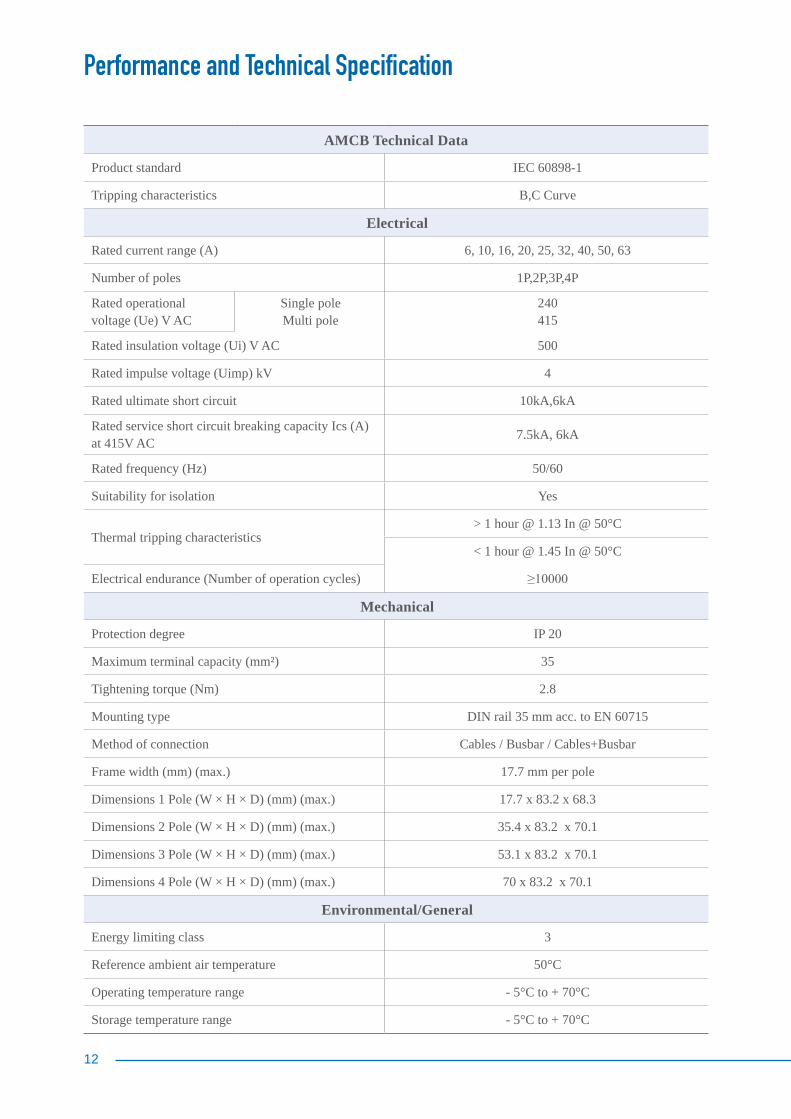
Performance and Technical Specification
AMCB Technical Data
Product standard IEC 60898-1
Tripping characteristics B,C Curve
Electrical
Rated current range (A) 6, 10, 16, 20, 25, 32, 40, 50, 63
Number of poles 1P,2P,3P,4P
Rated operational voltage (Ue) V AC
Single poleMulti pole
240415
Rated insulation voltage (Ui) V AC 500
Rated impulse voltage (Uimp) kV 4
Rated ultimate short circuit 10kA,6kA
Rated service short circuit breaking capacity Ics (A) at 415V AC 7.5kA, 6kA
Rated frequency (Hz) 50/60
Suitability for isolation Yes
Thermal tripping characteristics> 1 hour @ 1.13 In @ 50°C
< 1 hour @ 1.45 In @ 50°C
Electrical endurance (Number of operation cycles) ≥10000
Mechanical
Protection degree IP 20
Maximum terminal capacity (mm²) 35
Tightening torque (Nm) 2.8
Mounting type DIN rail 35 mm acc. to EN 60715
Method of connection Cables / Busbar / Cables+Busbar
Frame width (mm) (max.) 17.7 mm per pole
Dimensions 1 Pole (W × H × D) (mm) (max.) 17.7 x 83.2 x 68.3
Dimensions 2 Pole (W × H × D) (mm) (max.) 35.4 x 83.2 x 70.1
Dimensions 3 Pole (W × H × D) (mm) (max.) 53.1 x 83.2 x 70.1
Dimensions 4 Pole (W × H × D) (mm) (max.) 70 x 83.2 x 70.1
Environmental/General
Energy limiting class 3
Reference ambient air temperature 50°C
Operating temperature range - 5°C to + 70°C
Storage temperature range - 5°C to + 70°C
General Characteristics
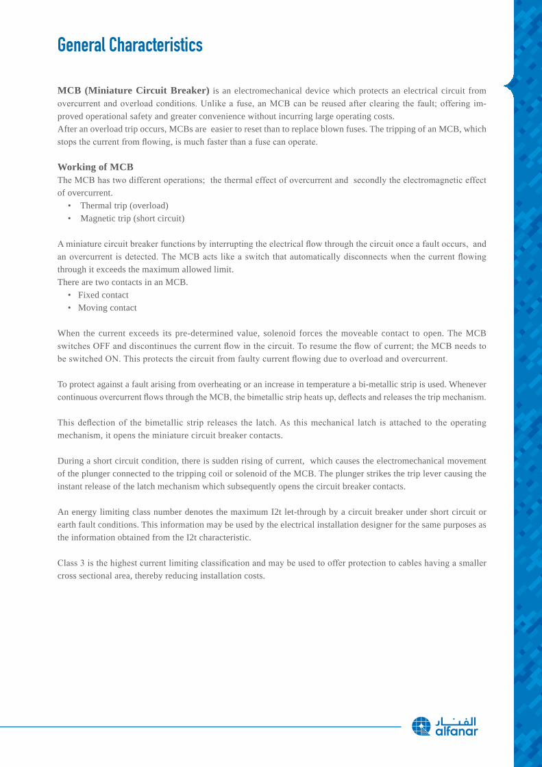
MCB (Miniature Circuit Breaker) is an electromechanical device which protects an electrical circuit from overcurrent and overload conditions. Unlike a fuse, an MCB can be reused after clearing the fault; offering im-proved operational safety and greater convenience without incurring large operating costs.After an overload trip occurs, MCBs are easier to reset than to replace blown fuses. The tripping of an MCB, which stops the current from flowing, is much faster than a fuse can operate.
Working of MCBThe MCB has two different operations; the thermal effect of overcurrent and secondly the electromagnetic effect of overcurrent. • Thermal trip (overload) • Magnetic trip (short circuit)
A miniature circuit breaker functions by interrupting the electrical flow through the circuit once a fault occurs, and an overcurrent is detected. The MCB acts like a switch that automatically disconnects when the current flowing through it exceeds the maximum allowed limit.There are two contacts in an MCB. • Fixed contact • Moving contact
When the current exceeds its pre-determined value, solenoid forces the moveable contact to open. The MCB switches OFF and discontinues the current flow in the circuit. To resume the flow of current; the MCB needs to be switched ON. This protects the circuit from faulty current flowing due to overload and overcurrent.
To protect against a fault arising from overheating or an increase in temperature a bi-metallic strip is used. Whenever continuous overcurrent flows through the MCB, the bimetallic strip heats up, deflects and releases the trip mechanism.
This deflection of the bimetallic strip releases the latch. As this mechanical latch is attached to the operating mechanism, it opens the miniature circuit breaker contacts. During a short circuit condition, there is sudden rising of current, which causes the electromechanical movement of the plunger connected to the tripping coil or solenoid of the MCB. The plunger strikes the trip lever causing the instant release of the latch mechanism which subsequently opens the circuit breaker contacts.
An energy limiting class number denotes the maximum I2t let-through by a circuit breaker under short circuit or earth fault conditions. This information may be used by the electrical installation designer for the same purposes as the information obtained from the I2t characteristic.
Class 3 is the highest current limiting classification and may be used to offer protection to cables having a smaller cross sectional area, thereby reducing installation costs.
14
General Characteristics
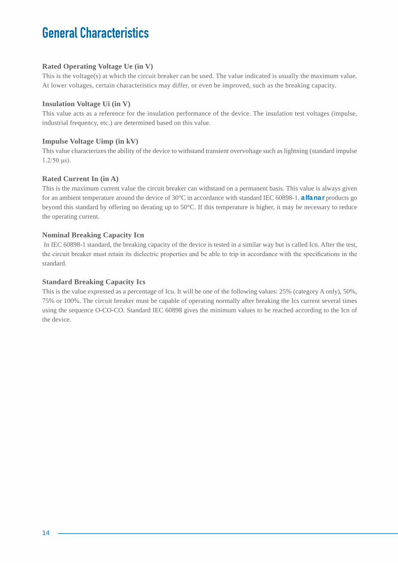
Rated Operating Voltage Ue (in V) This is the voltage(s) at which the circuit breaker can be used. The value indicated is usually the maximum value. At lower voltages, certain characteristics may differ, or even be improved, such as the breaking capacity.
Insulation Voltage Ui (in V) This value acts as a reference for the insulation performance of the device. The insulation test voltages (impulse, industrial frequency, etc.) are determined based on this value.
Impulse Voltage Uimp (in kV) This value characterizes the ability of the device to withstand transient overvoltage such as lightning (standard impulse 1.2/50 μs).
Rated Current In (in A)This is the maximum current value the circuit breaker can withstand on a permanent basis. This value is always given for an ambient temperature around the device of 30°C in accordance with standard IEC 60898-1. alfanar products go beyond this standard by offering no derating up to 50°C. If this temperature is higher, it may be necessary to reduce the operating current.
Nominal Breaking Capacity Icn In IEC 60898-1 standard, the breaking capacity of the device is tested in a similar way but is called Icn. After the test, the circuit breaker must retain its dielectric properties and be able to trip in accordance with the specifications in the standard.
Standard Breaking Capacity Ics This is the value expressed as a percentage of Icu. It will be one of the following values: 25% (category A only), 50%, 75% or 100%. The circuit breaker must be capable of operating normally after breaking the Ics current several times using the sequence O-CO-CO. Standard IEC 60898 gives the minimum values to be reached according to the Icn of the device.
General Characteristics
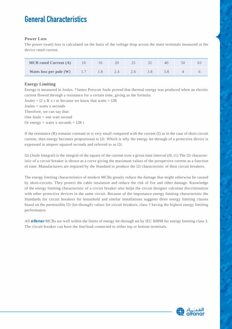
Power Loss The power (watt) loss is calculated on the basis of the voltage drop across the main terminals measured at the device rated current.
MCB rated Current (A) 10 16 20 25 32 40 50 63
Watts loss per pole (W) 1.7 1.8 2.4 2.6 3.8 3.8 4 6
Energy LimitingEnergy is measured in Joules. *James Prescott Joule proved that thermal energy was produced when an electric current flowed through a resistance for a certain time, giving us the formula:Joules = l2 x R x t or because we know that watts = l2RJoules = watts x secondsTherefore, we can say that:One Joule = one watt secondOr energy = watts x seconds = l2R t
If the resistance (R) remains constant or is very small compared with the current (I) as in the case of short circuit current, then energy becomes proportional to l2t. Which is why the energy let-through of a protective device is expressed in ampere squared seconds and referred to as l2t.
l2t (Joule Integral) is the integral of the square of the current over a given time interval (t0, t1) The l2t character-istic of a circuit breaker is shown as a curve giving the maximum values of the prospective current as a function of time. Manufacturers are required by the Standard to produce the l2t characteristic of their circuit breakers.
The energy limiting characteristics of modern MCBs greatly reduce the damage that might otherwise be caused by short-circuits. They protect the cable insulation and reduce the risk of fire and other damage. Knowledge of the energy limiting characteristic of a circuit breaker also helps the circuit designer calculate discrimination with other protective devices in the same circuit. Because of the importance energy limiting characteristic the Standards for circuit breakers for household and similar installations suggests three energy limiting classes based on the permissible l2t (let-through) values for circuit breakers; class 3 having the highest energy limiting performance.
All alfanar MCBs are well within the limits of energy let-through set by IEC 60898 for energy limiting class 3.The circuit breaker can have the line\load connected to either top or bottom terminals.
16
General Characteristics
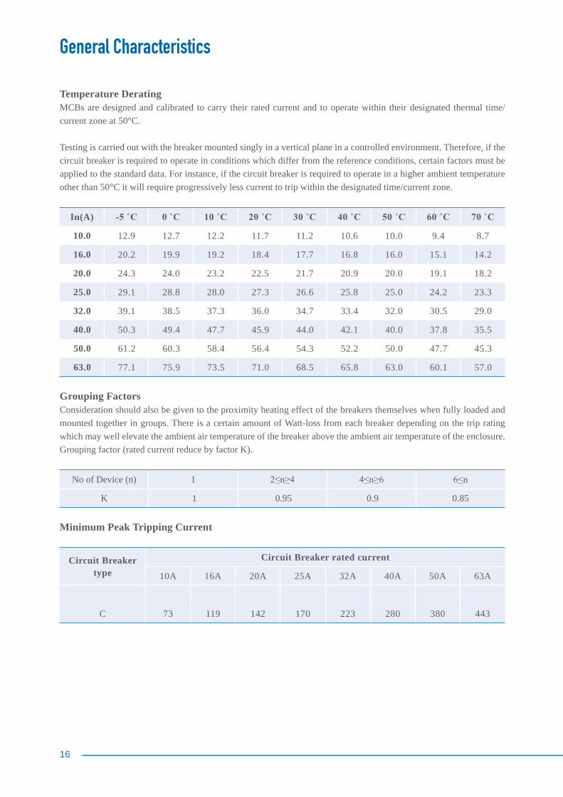
Temperature Derating MCBs are designed and calibrated to carry their rated current and to operate within their designated thermal time/current zone at 50°C.
Testing is carried out with the breaker mounted singly in a vertical plane in a controlled environment. Therefore, if the circuit breaker is required to operate in conditions which differ from the reference conditions, certain factors must be applied to the standard data. For instance, if the circuit breaker is required to operate in a higher ambient temperature other than 50°C it will require progressively less current to trip within the designated time/current zone.
In(A) -5 ˚C 0 ˚C 10 ˚C 20 ˚C 30 ˚C 40 ˚C 50 ˚C 60 ˚C 70 ˚C
10.0 12.9 12.7 12.2 11.7 11.2 10.6 10.0 9.4 8.7
16.0 20.2 19.9 19.2 18.4 17.7 16.8 16.0 15.1 14.2
20.0 24.3 24.0 23.2 22.5 21.7 20.9 20.0 19.1 18.2
25.0 29.1 28.8 28.0 27.3 26.6 25.8 25.0 24.2 23.3
32.0 39.1 38.5 37.3 36.0 34.7 33.4 32.0 30.5 29.0
40.0 50.3 49.4 47.7 45.9 44.0 42.1 40.0 37.8 35.5
50.0 61.2 60.3 58.4 56.4 54.3 52.2 50.0 47.7 45.3
63.0 77.1 75.9 73.5 71.0 68.5 65.8 63.0 60.1 57.0
Grouping FactorsConsideration should also be given to the proximity heating effect of the breakers themselves when fully loaded and mounted together in groups. There is a certain amount of Watt-loss from each breaker depending on the trip rating which may well elevate the ambient air temperature of the breaker above the ambient air temperature of the enclosure. Grouping factor (rated current reduce by factor K).
No of Device (n) 1 2≤n≥4 4≤n≥6 6≤n
K 1 0.95 0.9 0.85
Minimum Peak Tripping Current
Circuit Breaker type
Circuit Breaker rated current
10A 16A 20A 25A 32A 40A 50A 63A
C 73 119 142 170 223 280 380 443
General Characteristics
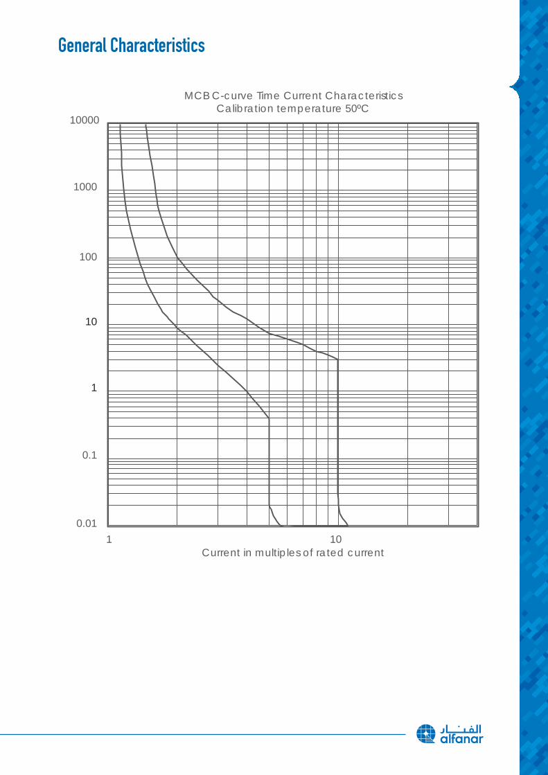
10000
MCB C-curve Time Current CharacteristicsCalibration temperature 50ºC
Current in multiples of rated current
1000
100
10
1
0.1
0.01
1 10
18
General Characteristics
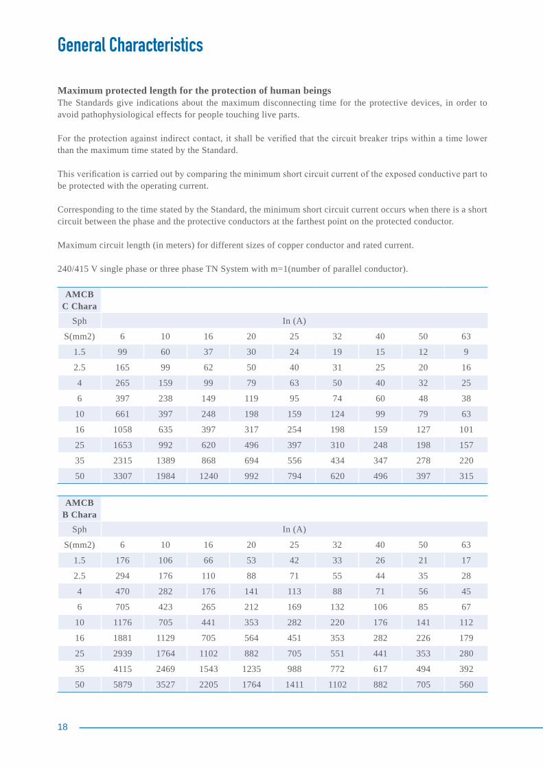
Maximum protected length for the protection of human beingsThe Standards give indications about the maximum disconnecting time for the protective devices, in order to avoid pathophysiological effects for people touching live parts.
For the protection against indirect contact, it shall be verified that the circuit breaker trips within a time lower than the maximum time stated by the Standard.
This verification is carried out by comparing the minimum short circuit current of the exposed conductive part to be protected with the operating current.
Corresponding to the time stated by the Standard, the minimum short circuit current occurs when there is a short circuit between the phase and the protective conductors at the farthest point on the protected conductor.
Maximum circuit length (in meters) for different sizes of copper conductor and rated current.
240/415 V single phase or three phase TN System with m=1(number of parallel conductor).
AMCB C Chara
Sph In (A)
S(mm2) 6 10 16 20 25 32 40 50 63
1.5 99 60 37 30 24 19 15 12 9
2.5 165 99 62 50 40 31 25 20 16
4 265 159 99 79 63 50 40 32 25
6 397 238 149 119 95 74 60 48 38
10 661 397 248 198 159 124 99 79 63
16 1058 635 397 317 254 198 159 127 101
25 1653 992 620 496 397 310 248 198 157
35 2315 1389 868 694 556 434 347 278 220
50 3307 1984 1240 992 794 620 496 397 315
AMCB B Chara
Sph In (A)
S(mm2) 6 10 16 20 25 32 40 50 63
1.5 176 106 66 53 42 33 26 21 17
2.5 294 176 110 88 71 55 44 35 28
4 470 282 176 141 113 88 71 56 45
6 705 423 265 212 169 132 106 85 67
10 1176 705 441 353 282 220 176 141 112
16 1881 1129 705 564 451 353 282 226 179
25 2939 1764 1102 882 705 551 441 353 280
35 4115 2469 1543 1235 988 772 617 494 392
50 5879 3527 2205 1764 1411 1102 882 705 560
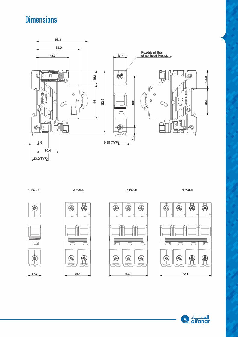
Dimensions
20
Installation and Ease of Use
1. InstallationCan be installed in the shown mounting position with Snap-On fixing in DIN rails as per EN 60 715, 35 mm width.
2.ConnectionEnsure that conductors are connected correctly and firmly. Max. tightening torque 2.8 Nm.
3. OperationMiniature circuit breakers are switched on by switching the handle in the direction of the nameplate. The operating lever now indicates the “I“ operating position. If an MCB trips, probably due to overload, it can be switched on again. If the MCB trips again immediately when trying to reclose after a short period of time, then do not continuously re-close an existing short circuit or earth fault. The MCB trips under overload, or short circuit or earth fault conditions, even if the operating lever is maintained in the ON position.
4. Cleaning the deviceMCBs soiled by installation work should be cleaned with a dry, or, if necessary, a damp and soapy cloth. Never use caustic agents or dissolvent.
5. Maintenancealfanar MCBs are maintenance-free.
6. Fitting of auxiliary switchesMCB has a knockout on the lower left hand side to add the auxiliary switch. Use a screwdriver to remove the knockout. Switch operating lever into the OFF position ”O“. Attach the auxiliary switch to the MCB and make sure that the outlines match the edges. Insert the driver extension of the auxiliary switch into the associated MCB handle. Then press the snap lock extension from the auxiliary, switch cover against the MCB to ensure it is firmly locked.
7. Wiring diagramsSupply optional, top or bottom, terminal designation in accordance with EN 50 005/ IEC 60947-1.

Ordering Data
Hassas Branch Breaker Type Din-Rail
No. of Poles Ampere Item Code1 Pole 06A HMD63N106C1 Pole 10A HMD63N110C1 Pole 16A HMD63N116C1 Pole 20A HMD63N120C1 Pole 25A HMD63N125C1 Pole 32A HMD63N132C1 Pole 40A HMD63N140C1 Pole 50A HMD63N150C1 Pole 63A HMD63N163C
2 Pole 06A HMD63N206C2 Pole 10A HMD63N210C2 Pole 16A HMD63N216C2 Pole 20A HMD63N220C2 Pole 25A HMD63N225C2 Pole 32A HMD63N232C2 Pole 40A HMD63N240C2 Pole 50A HMD63N250C2 Pole 63A HMD63N263C
3 Pole 06A HMD63N306C3 Pole 10A HMD63N310C3 Pole 16A HMD63N316C3 Pole 20A HMD63N320C3 Pole 25A HMD63N325C3 Pole 32A HMD63N332C3 Pole 40A HMD63N340C3 Pole 50A HMD63N350C3 Pole 63A HMD63N363C
4 Pole 06A HMD63N406C4 Pole 10A HMD63N410C4 Pole 16A HMD63N416C4 Pole 20A HMD63N420C4 Pole 25A HMD63N425C4 Pole 32A HMD63N432C4 Pole 40A HMD63N440C4 Pole 50A HMD63N450C4 Pole 63A HMD63N463C
22
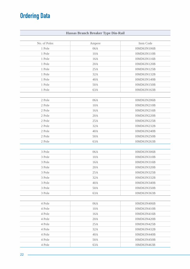
Ordering Data
Hassas Branch Breaker Type Din-Rail
No. of Poles Ampere Item Code1 Pole 06A HMD63N106B1 Pole 10A HMD63N110B1 Pole 16A HMD63N116B1 Pole 20A HMD63N120B1 Pole 25A HMD63N125B1 Pole 32A HMD63N132B1 Pole 40A HMD63N140B1 Pole 50A HMD63N150B1 Pole 63A HMD63N163B
2 Pole 06A HMD63N206B2 Pole 10A HMD63N210B2 Pole 16A HMD63N216B2 Pole 20A HMD63N220B2 Pole 25A HMD63N225B2 Pole 32A HMD63N232B2 Pole 40A HMD63N240B2 Pole 50A HMD63N250B2 Pole 63A HMD63N263B
3 Pole 06A HMD63N306B3 Pole 10A HMD63N310B3 Pole 16A HMD63N316B3 Pole 20A HMD63N320B3 Pole 25A HMD63N325B3 Pole 32A HMD63N332B3 Pole 40A HMD63N340B3 Pole 50A HMD63N350B3 Pole 63A HMD63N363B
4 Pole 06A HMD63N406B4 Pole 10A HMD63N410B4 Pole 16A HMD63N416B4 Pole 20A HMD63N420B4 Pole 25A HMD63N425B4 Pole 32A HMD63N432B4 Pole 40A HMD63N440B4 Pole 50A HMD63N450B4 Pole 63A HMD63N463B
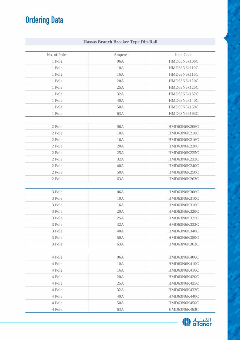
Ordering Data
Hassas Branch Breaker Type Din-Rail
No. of Poles Ampere Item Code1 Pole 06A HMD63N6k106C1 Pole 10A HMD63N6k110C1 Pole 16A HMD63N6k116C1 Pole 20A HMD63N6k120C1 Pole 25A HMD63N6k125C1 Pole 32A HMD63N6k132C1 Pole 40A HMD63N6k140C1 Pole 50A HMD63N6k150C1 Pole 63A HMD63N6k163C
2 Pole 06A HMD63N6K206C2 Pole 10A HMD63N6K210C2 Pole 16A HMD63N6K216C2 Pole 20A HMD63N6K220C2 Pole 25A HMD63N6K225C2 Pole 32A HMD63N6K232C2 Pole 40A HMD63N6K240C2 Pole 50A HMD63N6K250C2 Pole 63A HMD63N6K263C
3 Pole 06A HMD63N6K306C3 Pole 10A HMD63N6K310C3 Pole 16A HMD63N6K316C3 Pole 20A HMD63N6K320C3 Pole 25A HMD63N6K325C3 Pole 32A HMD63N6K332C3 Pole 40A HMD63N6K340C3 Pole 50A HMD63N6K350C3 Pole 63A HMD63N6K363C
4 Pole 06A HMD63N6K406C4 Pole 10A HMD63N6K410C4 Pole 16A HMD63N6K416C4 Pole 20A HMD63N6K420C4 Pole 25A HMD63N6K425C4 Pole 32A HMD63N6K432C4 Pole 40A HMD63N6K440C4 Pole 50A HMD63N6K450C4 Pole 63A HMD63N6K463C
www.alfanar.com