Embed Size (px)
Citation preview
HG Modular DevicesHGD / HRC / HSD / HEC / HIC
Contents
01
02
05
31
47
57
65
73
Profile
Features
HGD Miniature Circuit Breaker (MCB)
HRC Residual Current Circuit Breaker (RCCB)
HSD Miniature Switch Disconnector (MSD)
HEC Electronic Circuit Breaker
HIC Installation Contactor
Maintenance and Certifications

Hyundai Electric solely pursues the growth of our customers’
business. From power generation to power distribution,
we focus on developing and commercializing products
and solutions aimed at increasing the efficiency of energy
equipment as well as at proactively monitoring and controlling
assets in an integrated manner to improve our customers’
productivity and management efficiency. We are well aware
that our efforts add to the driving force behind our customers’
growth and contribute to the creation and maintenance of a
more dynamic world. We focus on achieving innovation and
strive to evolve continuously to shape a better tomorrow
based on today’s technological advancement.
Essential for Today,Potential for Tomorrow
1HYUNDAI ELECTRIC
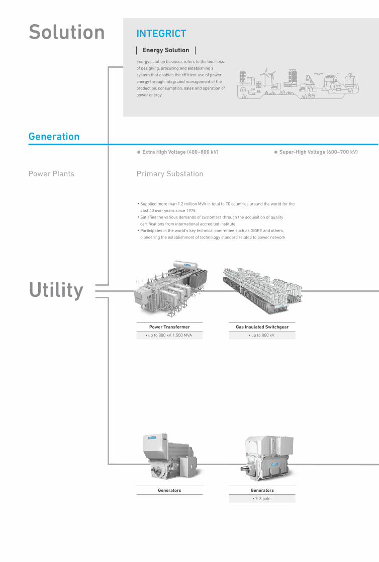
Power Transformer
• up to 800 kV, 1,500 MVA
Generators
Gas Insulated Switchgear
• up to 800 kV
Generators
• 2-3 pole
Solution
Utility
Generation
INTEGRICT
• Supplied more than 1.2 million MVA in total to 70 countries around the world for the
past 40 over years since 1978
• Satisfies the various demands of customers through the acquisition of quality
certifications from international accredited institute
• Participates in the world’s key technical committee such as GIGRE and others,
pioneering the establishment of technology standard related to power network
Primary Substation
• Extra High Voltage (400~800 kV) • Super-High Voltage (600~700 kV)
Power Plants
Energy solution business refers to the business
of designing, procuring and establishing a
system that enables the efficient use of power
energy through integrated management of the
production, consumption, sales and operation of
power energy.
Energy Solution
Gas Insulated Switchgear
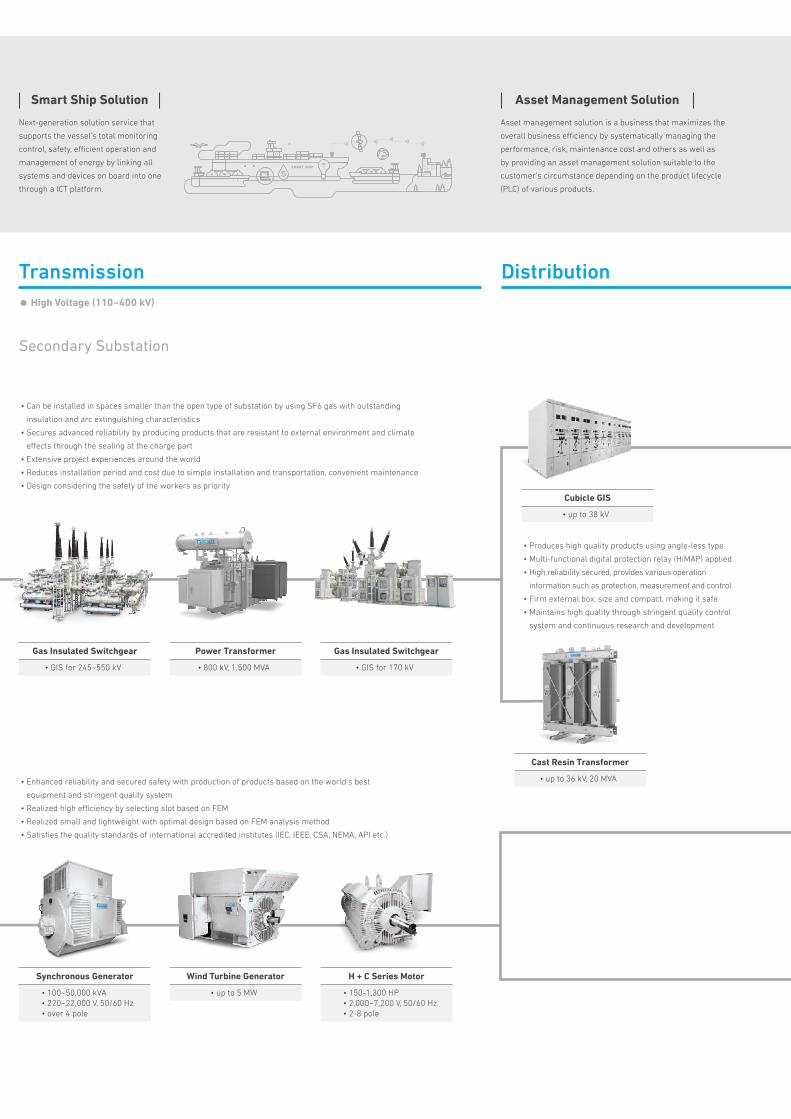
• GIS for 245~550 kV
Synchronous Generator
• 100~50,000 kVA• 220~22,000 V, 50/60 Hz• over 4 pole
Power Transformer
• 800 kV, 1,500 MVA
Wind Turbine Generator
• up to 5 MW
Gas Insulated Switchgear
• GIS for 170 kV
Cast Resin Transformer
• up to 36 kV, 20 MVA
Cubicle GIS
• up to 38 kV
H + C Series Motor
• 150-1,300 HP• 2,000~7,200 V, 50/60 Hz• 2-8 pole
• Can be installed in spaces smaller than the open type of substation by using SF6 gas with outstanding
insulation and arc extinguishing characteristics
• Secures advanced reliability by producing products that are resistant to external environment and climate
effects through the sealing at the charge part
• Extensive project experiences around the world
• Reduces installation period and cost due to simple installation and transportation, convenient maintenance
• Design considering the safety of the workers as priority
• Produces high quality products using angle-less type
• Multi-functional digital protection relay (HiMAP) applied
• High reliability secured, provides various operation
information such as protection, measurement and control
• Firm external box, size and compact, making it safe
• Maintains high quality through stringent quality control
system and continuous research and development
Transmission Distribution
Secondary Substation
• High Voltage (110~400 kV)
• Enhanced reliability and secured safety with production of products based on the world’s best
equipment and stringent quality system
• Realized high efficiency by selecting slot based on FEM
• Realized small and lightweight with optimal design based on FEM analysis method
• Satisfies the quality standards of international accredited institutes (IEC, IEEE, CSA, NEMA, API etc.)
Next-generation solution service that
supports the vessel’s total monitoring
control, safety, efficient operation and
management of energy by linking all
systems and devices on board into one
through a ICT platform.
Smart Ship Solution
Asset management solution is a business that maximizes the
overall business efficiency by systematically managing the
performance, risk, maintenance cost and others as well as
by providing an asset management solution suitable to the
customer’s circumstance depending on the product lifecycle
(PLC) of various products.
Asset Management Solution
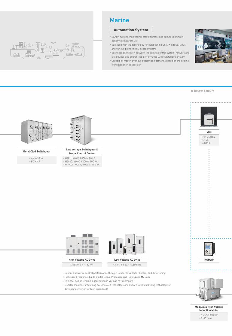
Metal Clad Switchgear
• up to 38 kV• EC, ANSI
VCB
• 7.2~25.8 kV• 50 kA• 4,000 A
HGMAP
Low Voltage Switchgear &Motor Control Center
• H8PU: 660 V, 3,000 A, 80 kA• H5600: 660 V, 3,000 A, 100 kA• HiMCC: 1,000 V, 5,000 A, 100 kA
High Voltage AC Drive
• 220~440 V, ~132 kW
Low Voltage AC Drive
• 3.3~13.8 kV, ~12,800 kW
Medium & High Voltage Induction Motor
• 150-30,000 HP• 2-30 pole
Marine
• Below 1,000 V
• Realizes powerful control performance through Sensor-less Vector Control and Auto Tuning
• High speed response due to Digital Signal Processor and High Speed My Com
• Compact design, enabling application in various environments
• Invertor manufactured using accumulated technology and know-how (outstanding technology of
developing inverter for high-speed rail)
• SCADA system engineering, establishment and commissioning in
nationwide network unit
• Equipped with the technology for establishing Unix, Windows, Linus
and various platform O.S-based systems
• Seamless connection between the central control system, network and
site devices and guaranteed performance with outstanding system
• Capable of meeting various customized demands based on the original
technologies in possession
Automation System
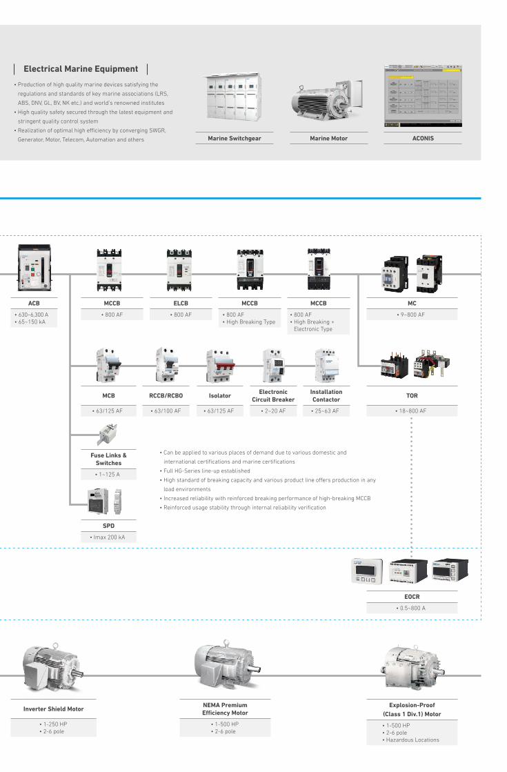
ACB
• 630~6,300 A• 65~150 kA
MCCB
• 800 AF• High Breaking Type
ELCB
• 800 AF
Isolator
• 63/125 AF
Installation Contactor
• 25~63 AF
MCCB
• 800 AF• High Breaking +
Electronic Type
MC
• 9~800 AF
TOR
• 18~800 AF
EOCR
• 0.5~800 A
MCCB
• 800 AF
MCB
• 63/125 AF
Fuse Links & Switches
• 1~125 A
SPD
• Imax 200 kA
RCCB/RCBO
• 63/100 AF
Electronic Circuit Breaker
• 2~20 AF
Marine Switchgear Marine Motor ACONIS
NEMA Premium Efficiency Motor
• 1-500 HP• 2-6 pole
Inverter Shield Motor
• 1-250 HP• 2-6 pole
Explosion-Proof(Class 1 Div.1) Motor
• 1-500 HP• 2-6 pole• Hazardous Locations
• Below 1,000 V
• Can be applied to various places of demand due to various domestic and
international certifications and marine certifications
• Full HG-Series line-up established
• High standard of breaking capacity and various product line offers production in any
load environments
• Increased reliability with reinforced breaking performance of high-breaking MCCB
• Reinforced usage stability through internal reliability verification
Electrical Marine Equipment
• Production of high quality marine devices satisfying the
regulations and standards of key marine associations (LRS,
ABS, DNV, GL, BV, NK etc.) and world’s renowned institutes
• High quality safety secured through the latest equipment and
stringent quality control system
• Realization of optimal high efficiency by converging SWGR,
Generator, Motor, Telecom, Automation and others

Features
HGD_63N_SPACResidence
Industry
Marine
Easy to remove, simple to install and repair with inscription window
Reliable short circuit capacity offering more stable and better protection to household electric appliances
IEC 60947-2 certified for industrial installation
Approved marine certificate
Applicable to Various Location
Building
2 HG Modular Devices
3HYUNDAI ELECTRIC
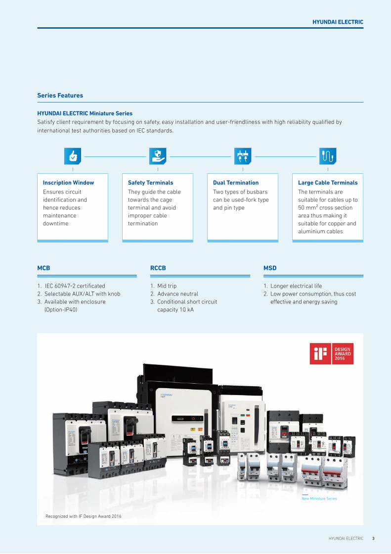
Series Features
HYUNDAI ELECTRIC Miniature Series Satisfy client requirement by focusing on safety, easy installation and user-friendliness with high reliability qualified by
international test authorities based on IEC standards.
1. IEC 60947-2 certificated2. Selectable AUX/ALT with knob 3. Available with enclosure
(Option-IP40)
MCB
1. Longer electrical life2. Low power consumption, thus cost
effective and energy saving
MSD
1. Mid trip2. Advance neutral3. Conditional short circuit
capacity 10 kA
RCCB
Recognized with IF Design Award 2016
New Miniature Series
Inscription Window
Ensures circuit identification and hence reduces maintenance downtime
Safety Terminals
They guide the cabletowards the cage terminal and avoid improper cable termination
Dual Termination
Two types of busbarscan be used-fork type and pin type
Large Cable Terminals
The terminals are suitable for cables up to 50 mm² cross section area thus making it suitable for copper and aluminium cables
HYUNDAI ELECTRIC
Product Overview
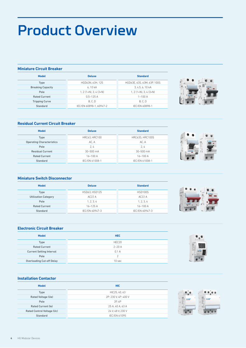
Miniature Circuit Breaker
Model Deluxe Standard
Type HGD63N, 63H, 125 HGD63E, 63S, 63M, 63P, 100S
Breaking Capacity 6, 10 kA 3, 4.5, 6, 10 kA
Pole 1, 2 (1+N), 3, 4 (3+N) 1, 2 (1+N), 3, 4 (3+N)
Rated Current 0.5~125 A 1~100 A
Tripping Curve B, C, D B, C, D
Standard IEC/EN 60898-1, 60947-2 IEC/EN 60898-1
Residual Current Circuit Breaker
Model Deluxe Standard
Type HRC63, HRC100 HRC63S, HRC100S
Operating Characteristics AC, A AC, A
Pole 2, 4 2, 4
Residual Current 30~500 mA 30~500 mA
Rated Current 16~100 A 16~100 A
Standard IEC/EN 61008-1 IEC/EN 61008-1
Miniature Switch Disconnector
Model Deluxe Standard
Type HSD63, HSD125 HSD100S
Utilization Category AC22 A AC22 A
Pole 1, 2, 3, 4 1, 2, 3, 4
Rated Current 16~125 A 16~100 A
Standard IEC/EN 60947-3 IEC/EN 60947-3
Electronic Circuit Breaker
Model HEC
Type HEC20
Rated Current 2~20 A
Current Setting Interval 0.1 A
Pole 2
Overloading Cut-off Delay 10 sec
Installation Contactor
Model HIC
Type HIC25, 40, 63
Rated Voltage (Ue) 2P: 230 V, 4P: 400 V
Pole 2P, 4P
Rated Current (Ie) 25 A, 40 A, 63 A
Rated Control Voltage (Uc) 24 V, 48 V, 230 V
Standard IEC/EN 61095
4 HG Modular Devices

5HYUNDAI ELECTRIC
Features 06
Selection Table 08
Accessories 10
Technical Data 17
Dimensions 27
Order Information 29
HGDMiniature Circuit Breaker
6 HG Modular Devices
Features
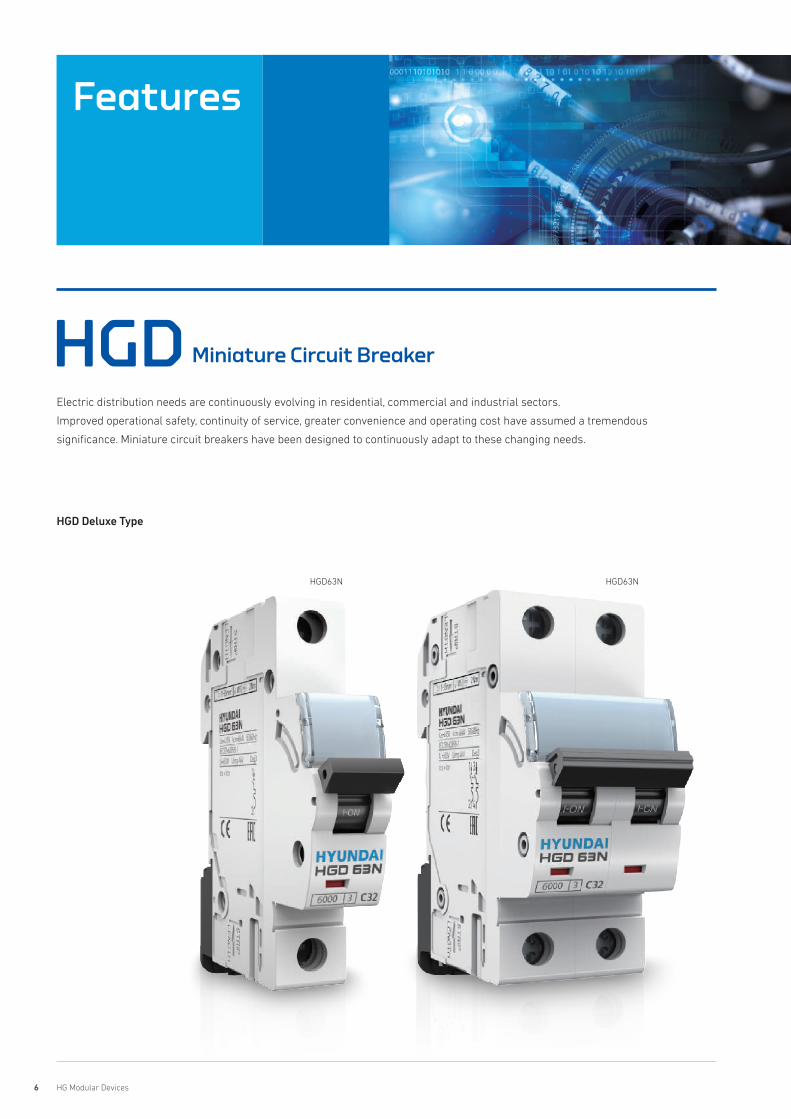
HGD Miniature Circuit Breaker
Electric distribution needs are continuously evolving in residential, commercial and industrial sectors.
Improved operational safety, continuity of service, greater convenience and operating cost have assumed a tremendous
significance. Miniature circuit breakers have been designed to continuously adapt to these changing needs.
HGD63N HGD63N
HGD Deluxe Type
7HYUNDAI ELECTRIC
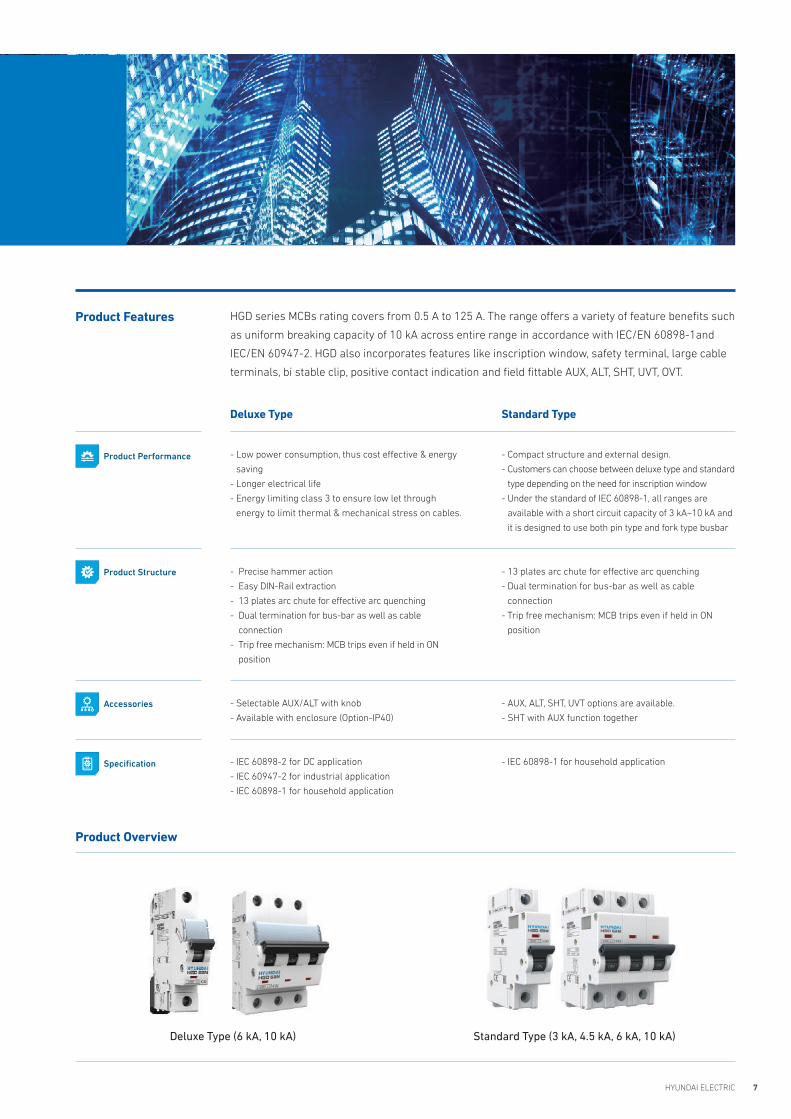
HGD series MCBs rating covers from 0.5 A to 125 A. The range offers a variety of feature benefits such
as uniform breaking capacity of 10 kA across entire range in accordance with IEC/EN 60898-1and
IEC/EN 60947-2. HGD also incorporates features like inscription window, safety terminal, large cable
terminals, bi stable clip, positive contact indication and field fittable AUX, ALT, SHT, UVT, OVT.
Product Features
Product Overview
Deluxe Type (6 kA, 10 kA) Standard Type (3 kA, 4.5 kA, 6 kA, 10 kA)
Deluxe Type
- Low power consumption, thus cost effective & energy
saving
- Longer electrical life
- Energy limiting class 3 to ensure low let through
energy to limit thermal & mechanical stress on cables.
- Precise hammer action
- Easy DIN-Rail extraction
- 13 plates arc chute for effective arc quenching
- Dual termination for bus-bar as well as cable
connection
- Trip free mechanism: MCB trips even if held in ON
position
- Selectable AUX/ALT with knob
- Available with enclosure (Option-IP40)
- IEC 60898-2 for DC application
- IEC 60947-2 for industrial application
- IEC 60898-1 for household application
Standard Type
- Compact structure and external design.
- Customers can choose between deluxe type and standard
type depending on the need for inscription window
- Under the standard of IEC 60898-1, all ranges are
available with a short circuit capacity of 3 kA~10 kA and
it is designed to use both pin type and fork type busbar
- 13 plates arc chute for effective arc quenching
- Dual termination for bus-bar as well as cable
connection
- Trip free mechanism: MCB trips even if held in ON
position
- AUX, ALT, SHT, UVT options are available.
- SHT with AUX function together
- IEC 60898-1 for household application
Product Performance
Product Structure
Accessories
Specification
8 HG Modular Devices
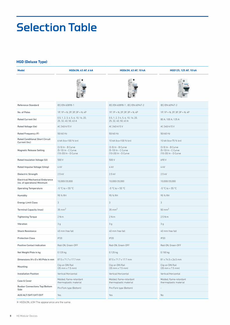
Selection Table
Model HGD63N, 63 AF, 6 kA HGD63H, 63 AF, 10 kA HGD125, 125 AF, 10 kA
Reference Standard IEC/EN 60898-1 IEC/EN 60898-1 ; IEC/EN 60947-2 IEC/EN 60947-2
No. of Poles 1P, 1P + N, 2P, 3P, 3P + N, 4P 1P, 1P + N, 2P, 3P, 3P + N, 4P 1P, 1P + N, 2P, 3P, 3P + N, 4P
Rated Current (In)0.5, 1, 2, 3, 4, 5, 6, 10, 16, 20, 25, 32, 40, 50, 63 A
0.5, 1, 2, 3 4, 5, 6, 10, 16, 20, 25, 32, 40, 50, 63 A
80 A, 100 A, 125 A
Rated Voltage (Ue) AC 240/415 V AC 240/415 V AC 240/415 V
Rated Frequency (F) 50/60 Hz 50/60 Hz 50/60 Hz
Rated Conditional Short Circuit Current (Inc)
6 kA (Ics=100 % Icn) 10 kA (Ics=100 % Icn) 10 kA (Ics=75 % Icn)
Magnetic Release Setting(3-5) In - B Curve(5-10) In - C Curve(10-20) In - D Curve
(3-5) In - B Curve(5-10) In - C Curve(10-20) In - D Curve
(3-5) In - B Curve(5-10) In - C Curve(10-20) In - D Curve
Rated Insulation Voltage (Ui) 500 V 500 V 690 V
Rated Impulse Voltage (Uimp) 4 kV 4 kV 4 kV
Dielectric Strength 2.5 kV 2.5 kV 2.5 kV
Electrical/Mechanical Endurance (no. of operations) Minimum
10,000/20,000 10,000/20,000 10,000/20,000
Operating Temperature -5 °C to + 55 °C -5 °C to + 55 °C -5 °C to + 55 °C
Humidity 95 % RH 95 % RH 95 % RH
Energy Limit Class 3 3 3
Terminal Capacity (max) 35 mm2 35 mm2 50 mm2
Tightening Torque 2 N·m 2 N·m 2.5 N·m
Vibration 3 g 3 g 3 g
Shock Resistance 40 mm free fall 40 mm free fall 40 mm free fall
Protection Class IP20 IP20 IP20
Positive Contact Indication Red-ON, Green-OFF Red-ON, Green-OFF Red-ON, Green-OFF
Net Weight/Pole in kg 0.125 kg 0.125 kg 0.150 kg
Dimensions (H x D x W)/Pole in mm 87.5 x 71.7 x 17.7 mm 87.5 x 71.7 x 17.7 mm 81 x 74.5 x 26.5 mm
MountingClip on DIN Rail(35 mm x 7.5 mm)
Clip on DIN Rail(35 mm x 7.5 mm)
Clip on DIN Rail(35 mm x 7.5 mm)
Installation Position Vertical/Horizontal Vertical/Horizontal Vertical/Horizontal
Case & CoverMolded, flame-retardant thermoplastic material
Molded, flame-retardant thermoplastic material
Molded, flame-retardant thermoplastic material
Busbar Connections Top/Bottom Side
Pin/Fork type (Bottom) Pin/Fork type (Bottom) -
AUX/ALT/SHT/UVT/OVT Yes Yes No
HGD (Deluxe Type)
※ HGD63N, 63H The appearance are the same.
9HYUNDAI ELECTRIC
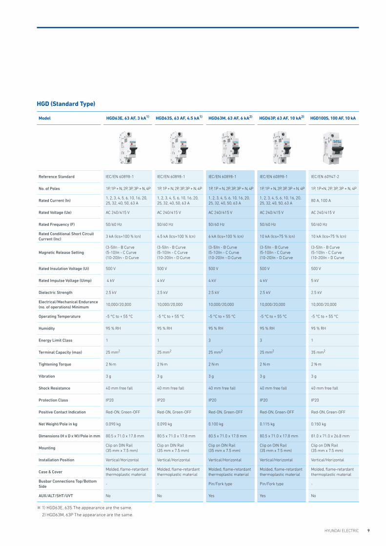
Model HGD63E, 63 AF, 3 kA1) HGD63S, 63 AF, 4.5 kA1) HGD63M, 63 AF, 6 kA2) HGD63P, 63 AF, 10 kA2) HGD100S, 100 AF, 10 kA
Reference Standard IEC/EN 60898-1 IEC/EN 60898-1 IEC/EN 60898-1 IEC/EN 60898-1 IEC/EN 60947-2
No. of Poles 1P, 1P + N, 2P, 3P, 3P + N, 4P 1P, 1P + N, 2P, 3P, 3P + N, 4P 1P, 1P + N, 2P, 3P, 3P + N, 4P 1P, 1P + N, 2P, 3P, 3P + N, 4P 1P, 1P+N, 2P, 3P, 3P + N, 4P
Rated Current (In)1, 2, 3, 4, 5, 6, 10, 16, 20,25, 32, 40, 50, 63 A
1, 2, 3, 4, 5, 6, 10, 16, 20,25, 32, 40, 50, 63 A
1, 2, 3, 4, 5, 6, 10, 16, 20,25, 32, 40, 50, 63 A
1, 2, 3, 4, 5, 6, 10, 16, 20,25, 32, 40, 50, 63 A
80 A, 100 A
Rated Voltage (Ue) AC 240/415 V AC 240/415 V AC 240/415 V AC 240/415 V AC 240/415 V
Rated Frequency (F) 50/60 Hz 50/60 Hz 50/60 Hz 50/60 Hz 50/60 Hz
Rated Conditional Short Circuit Current (Inc)
3 kA (Ics=100 % Icn) 4.5 kA (Ics=100 % Icn) 6 kA (Ics=100 % Icn) 10 kA (Ics=75 % Icn) 10 kA (Ics=75 % Icn)
Magnetic Release Setting(3-5)In - B Curve(5-10)In - C Curve(10-20)In - D Curve
(3-5)In - B Curve(5-10)In - C Curve(10-20)In - D Curve
(3-5)In - B Curve(5-10)In - C Curve(10-20)In - D Curve
(3-5)In - B Curve(5-10)In - C Curve(10-20)In - D Curve
(3-5)In - B Curve(5-10)In - C Curve(10-20)In - D Curve
Rated Insulation Voltage (Ui) 500 V 500 V 500 V 500 V 500 V
Rated Impulse Voltage (Uimp) 4 kV 4 kV 4 kV 4 kV 5 kV
Dielectric Strength 2.5 kV 2.5 kV 2.5 kV 2.5 kV 2.5 kV
Electrical/Mechanical Endurance (no. of operations) Minimum
10,000/20,000 10,000/20,000 10,000/20,000 10,000/20,000 10,000/20,000
Operating Temperature -5 °C to + 55 °C -5 °C to + 55 °C -5 °C to + 55 °C -5 °C to + 55 °C -5 °C to + 55 °C
Humidity 95 % RH 95 % RH 95 % RH 95 % RH 95 % RH
Energy Limit Class 1 1 3 3 1
Terminal Capacity (max) 25 mm2 25 mm2 25 mm2 25 mm2 35 mm2
Tightening Torque 2 N·m 2 N·m 2 N·m 2 N·m 2 N·m
Vibration 3 g 3 g 3 g 3 g 3 g
Shock Resistance 40 mm free fall 40 mm free fall 40 mm free fall 40 mm free fall 40 mm free fall
Protection Class IP20 IP20 IP20 IP20 IP20
Positive Contact Indication Red-ON, Green-OFF Red-ON, Green-OFF Red-ON, Green-OFF Red-ON, Green-OFF Red-ON, Green-OFF
Net Weight/Pole in kg 0.090 kg 0.090 kg 0.100 kg 0.115 kg 0.150 kg
Dimensions (H x D x W)/Pole in mm 80.5 x 71.0 x 17.8 mm 80.5 x 71.0 x 17.8 mm 80.5 x 71.0 x 17.8 mm 80.5 x 71.0 x 17.8 mm 81.0 x 71.0 x 26.8 mm
MountingClip on DIN Rail (35 mm x 7.5 mm)
Clip on DIN Rail(35 mm x 7.5 mm)
Clip on DIN Rail(35 mm x 7.5 mm)
Clip on DIN Rail(35 mm x 7.5 mm)
Clip on DIN Rail(35 mm x 7.5 mm)
Installation Position Vertical/Horizontal Vertical/Horizontal Vertical/Horizontal Vertical/Horizontal Vertical/Horizontal
Case & CoverMolded, flame-retardantthermoplastic material
Molded, flame-retardantthermoplastic material
Molded, flame-retardantthermoplastic material
Molded, flame-retardantthermoplastic material
Molded, flame-retardantthermoplastic material
Busbar Connections Top/Bottom Side
- - Pin/Fork type Pin/Fork type -
AUX/ALT/SHT/UVT No No Yes Yes No
HGD (Standard Type)
※ 1) HGD63E, 63S The appearance are the same.
2) HGD63M, 63P The appearance are the same.
10 HG Modular Devices
Accessories (Deluxe Type)
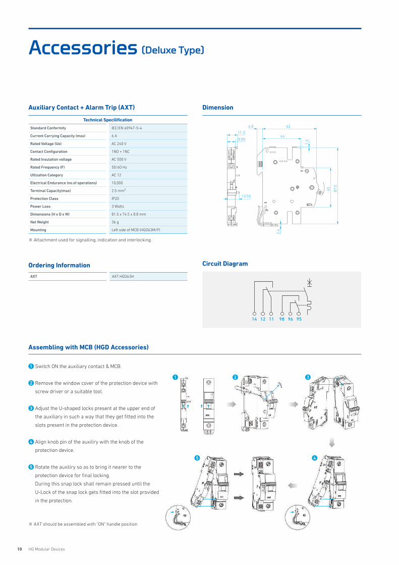
Auxiliary Contact + Alarm Trip (AXT) Dimension
Circuit Diagram
Technical Specilification
Standard Conformity IEC/EN 60947-5-4
Current Carrying Capacity (max) 6 A
Rated Voltage (Ue) AC 240 V
Contact Configuration 1NO + 1NC
Rated Insulation voltage AC 500 V
Rated Frequency (F) 50/60 Hz
Utlization Category AC 12
Electrical Endurance (no.of operations) 10,000
Terminal Capacity(max) 2.5 mm²
Protection Class IP20
Power Loss 3 Watts
Dimensions (H x D x W) 81.5 x 74.5 x 8.8 mm
Net Weight 36 g
Mounting Left side of MCB (HGD63M/P)
Ordering Information
AXT AXT HGD63H
Assembling with MCB (HGD Accessories)
※ Attachment used for signalling, indication and interlocking.
※ AXT should be assembled with "ON" handle position
45 87.5
6.8
44
62
1.4
2.4
8.85
11.3
13.55
14 9812 9611 95
1 Switch ON the auxiliary contact & MCB.
2 Remove the window cover of the protection device with
screw driver or a suitable tool.
3 Adjust the U-shaped locks present at the upper end of
the auxiliary in such a way that they get fitted into the
slots present in the protection device.
4 Align knob pin of the auxiliry with the knob of the
protection device.
5 Rotate the auxiliry so as to bring it nearer to the
protection device for final locking.
During this snap lock shall remain pressed until the
U-Lock of the snap lock gets fitted into the slot provided
in the protection.
2 3
45
1
11HYUNDAI ELECTRIC
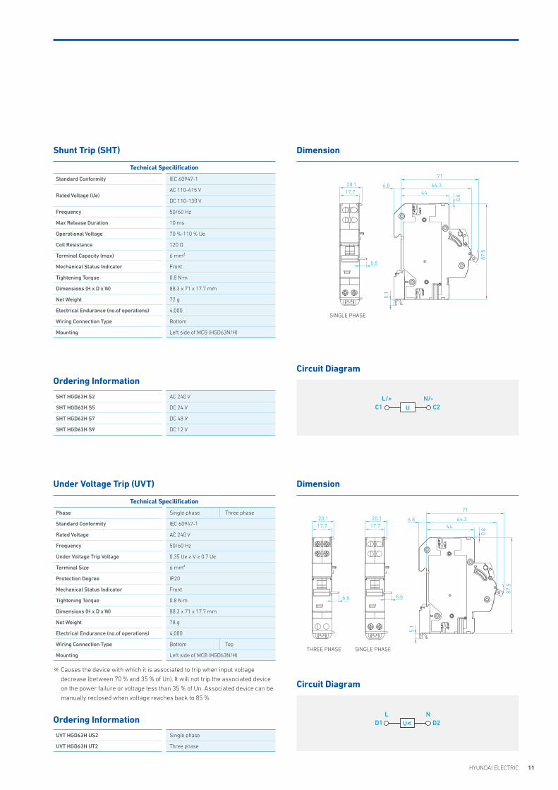
Shunt Trip (SHT)
Under Voltage Trip (UVT)
Dimension
Dimension
Technical Specilification
Standard Conformity IEC 60947-1
Rated Voltage (Ue)AC 110-415 V
DC 110-130 V
Frequency 50/60 Hz
Max Release Duration 10 ms
Operational Voltage 70 %-110 % Ue
Coil Resistance 120 Ω
Terminal Capacity (max) 6 mm²
Mechanical Status Indicator Front
Tightening Torque 0.8 N·m
Dimensions (H x D x W) 88.3 x 71 x 17.7 mm
Net Weight 72 g
Electrical Endurance (no.of operations) 4,000
Wiring Connection Type Bottom
Mounting Left side of MCB (HGD63N/H)
Ordering Information
SHT HGD63H S2 AC 240 V
SHT HGD63H S5 DC 24 V
SHT HGD63H S7 DC 48 V
SHT HGD63H S9 DC 12 V
Technical Specilification
Phase Single phase Three phase
Standard Conformity IEC 60947-1
Rated Voltage AC 240 V
Frequency 50/60 Hz
Under Voltage Trip Voltage 0.35 Ue ≥ V ≥ 0.7 Ue
Terminal Size 6 mm²
Protection Degree IP20
Mechanical Status Indicator Front
Tightening Torque 0.8 N·m
Dimensions (H x D x W) 88.3 x 71 x 17.7 mm
Net Weight 78 g
Electrical Endurance (no.of operations) 4,000
Wiring Connection Type Bottom Top
Mounting Left side of MCB (HGD63N/H)
Ordering Information
UVT HGD63H US2 Single phase
UVT HGD63H UT2 Three phase
Circuit Diagram
Circuit Diagram
※ Causes the device with which it is associated to trip when input voltage
decrease (between 70 % and 35 % of Un). It will not trip the associated device
on the power failure or voltage less than 35 % of Un. Associated device can be
manually reclosed when voltage reaches back to 85 %.
4464.3
0.8
6.8
71
87.5
17.720.1
5.1
6.6
SINGLE PHASE
17.720.1
4464.3
0.8
6.8
7187
.5
17.720.1
5.1
6.6 6.6
SINGLE PHASE THREE PHASE
C2C1L/+ N/-
U
D2D1L N
U<
12 HG Modular Devices
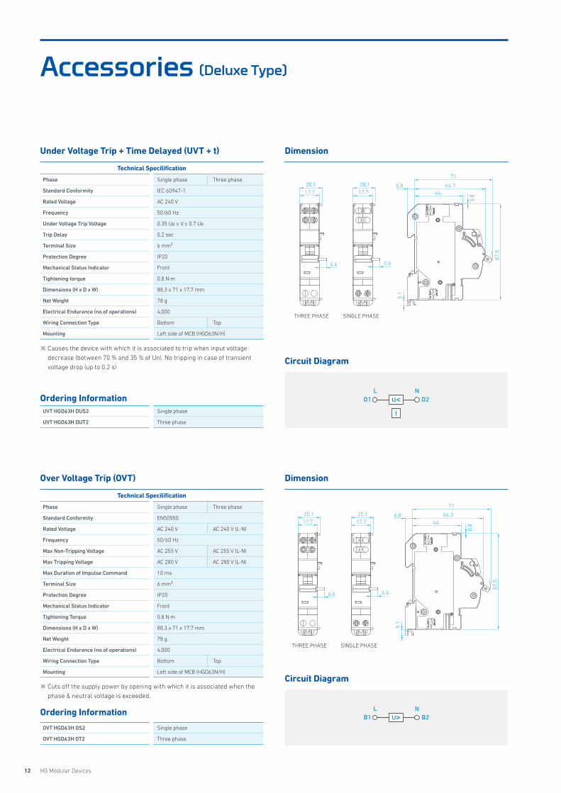
Accessories (Deluxe Type)
Under Voltage Trip + Time Delayed (UVT + t)
Over Voltage Trip (OVT)
Dimension
Dimension
Technical Specilification
Phase Single phase Three phase
Standard Conformity IEC 60947-1
Rated Voltage AC 240 V
Frequency 50/60 Hz
Under Voltage Trip Voltage 0.35 Ue ≥ V ≥ 0.7 Ue
Trip Delay 0.2 sec
Terminal Size 6 mm²
Protection Degree IP20
Mechanical Status Indicator Front
Tightening torque 0.8 N·m
Dimensions (H x D x W) 88.3 x 71 x 17.7 mm
Net Weight 78 g
Electrical Endurance (no.of operations) 4,000
Wiring Connection Type Bottom Top
Mounting Left side of MCB (HGD63N/H)
Ordering InformationUVT HGD63H DUS2 Single phase
UVT HGD63H DUT2 Three phase
Technical Specilification
Phase Single phase Three phase
Standard Conformity EN50550
Rated Voltage AC 240 V AC 240 V (L-N)
Frequency 50/60 Hz
Max Non-Tripping Voltage AC 255 V AC 255 V (L-N)
Max Tripping Voltage AC 280 V AC 280 V (L-N)
Max Duration of Impulse Command 10 ms
Terminal Size 6 mm²
Protection Degree IP20
Mechanical Status Indicator Front
Tightening Torque 0.8 N·m
Dimensions (H x D x W) 88.3 x 71 x 17.7 mm
Net Weight 78 g
Electrical Endurance (no.of operations) 4,000
Wiring Connection Type Bottom Top
Mounting Left side of MCB (HGD63N/H)
Ordering Information
OVT HGD63H OS2 Single phase
OVT HGD63H OT2 Three phase
Circuit Diagram
Circuit Diagram
※ Causes the device with which it is associated to trip when input voltage
decrease (between 70 % and 35 % of Un). No tripping in case of transient
voltage drop (up to 0.2 s)
※ Cuts off the supply power by opening with which it is associated when the
phase & neutral voltage is exceeded.
17.720.1
4464.3
0.8
6.8
71
87.5
17.720.1
5.1
6.6 6.6
SINGLE PHASE THREE PHASE
17.720.1
4464.3
0.8
6.8
71
87.5
17.720.1
5.1
6.6 6.6
SINGLE PHASE THREE PHASE
D2D1L N
t
U<
B2B1L N
U>
13HYUNDAI ELECTRIC
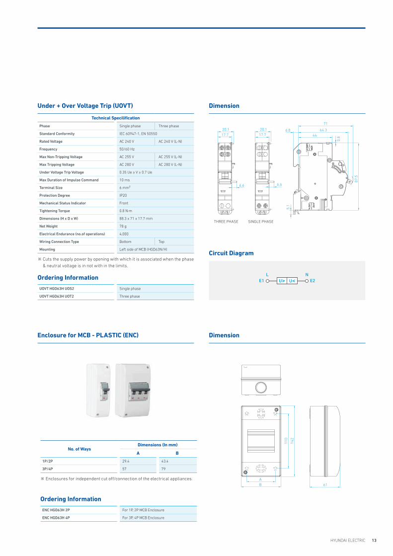
Under + Over Voltage Trip (UOVT)
Enclosure for MCB - PLASTIC (ENC)
Dimension
Dimension
Technical Specilification
Phase Single phase Three phase
Standard Conformity IEC 60947-1, EN 50550
Rated Voltage AC 240 V AC 240 V (L-N)
Frequency 50/60 Hz
Max Non-Tripping Voltage AC 255 V AC 255 V (L-N)
Max Tripping Voltage AC 280 V AC 280 V (L-N)
Under Voltage Trip Voltage 0.35 Ue ≥ V ≥ 0.7 Ue
Max Duration of Impulse Command 10 ms
Terminal Size 6 mm²
Protection Degree IP20
Mechanical Status Indicator Front
Tightening Torque 0.8 N·m
Dimensions (H x D x W) 88.3 x 71 x 17.7 mm
Net Weight 78 g
Electrical Endurance (no.of operations) 4,000
Wiring Connection Type Bottom Top
Mounting Left side of MCB (HGD63N/H)
Ordering Information
UOVT HGD63H UOS2 Single phase
UOVT HGD63H UOT2 Three phase
No. of WaysDimensions (In mm)
A B
1P/2P 29.4 43.4
3P/4P 57 79
Ordering Information
ENC HGD63H 2P For 1P, 2P MCB Enclosure
ENC HGD63H 4P For 3P, 4P MCB Enclosure
Circuit Diagram※ Cuts the supply power by opening with which it is associated when the phase
& neutral voltage is in not with in the limits.
※ Enclosures for independent cut off/connection of the electrical appliances.
17.720.1
4464.3
0.8
6.8
71
87.5
17.720.1
5.1
6.6 6.6
SINGLE PHASE THREE PHASE
AB 61
110
142
E2E1L N
U<U>

14 HG Modular Devices
Accessories (Standard Type)
Auxiliary Contact (AUX)
Alarm Trip (ALT)
Dimension
Dimension
Technical Specilification
Standard Conformity IEC/EN 60947-5-4
Current Carrying Capacity (max) 6 A
Rated Voltage (Ue) AC 240 V
Contact Configuration 1NO + 1NC
Rated Insulation Voltage AC 500 V
Rated Frequency (F) 50/60 Hz
Utlization Category AC 12
Electrical Endurance (no.of operations) 10,000
Terminal Capacity (max) 2.5 mm²
Protection Class IP20
Dimensions (H x D x W) 81.5 x 74.5 x 8.8 mm
Terminal Capacity (max) 35 mm²
Net Weight 32 g
Mounting Left side of MCB (HGD63M/P)
OperatingCurrent
Operating Power Voltage Current
AC415 V 3 A
240 V 6 A
DC
130 V 1 A
48 V 2 A
24 V 6 A
Ordering Information
AUX HGD63P
Technical Specilification
Standard Conformity IEC/EN 60947-5-4
Current Carrying Capacity (max) 6 A
Rated Voltage (Ue) AC 240 V
Contact Configuration 1NO + 1NC
Rated Insulation Voltage AC 500 V
Rated Frequency (F) 50/60 Hz
Utlization Category AC 12
Electrical Endurance (no.of operations) 10,000
Terminal Capacity (max) 2.5 mm²
Protection Class IP20
Dimensions (H x D x W) 81.5 x 74.5 x 8.8 mm
Net Weight 32 g
Mounting Left side of MCB (HGD63M/P)
OperatingCurrent
Operating Power Voltage Current
AC415 V 3 A
240 V 6 A
DC
130 V 1 A
48 V 2 A
24 V 6 A
Ordering Information
ALT HGD63P
Circuit Diagram
Circuit Diagram
※ Attachment used for signalling, indication and interlocking point 11 and 14
are connected when circuit is closed. Point 11 and 12 are connected when
circuit is open.
※ Attachment used for signalling, indication and interlocking※ Point 91 and 92 are connected when circuit is closed.
Point 91 and 94 are connected when the breaker trips due to fault.
Point 91 and 92 are connected when the breaker trips by manual operation.
Meanwhile, point 91 and 94 are disconnected.
74.545
.381
.518
74.5
45.3
81.5
8.8
74.5
45.3
81.5
8.8
74.5
45.3
81.5
18
74.5
45.3
81.5
8.8
74.5
45.3
81.5
8.8
11
12
14
L/+
91
94
92
L/+
15HYUNDAI ELECTRIC
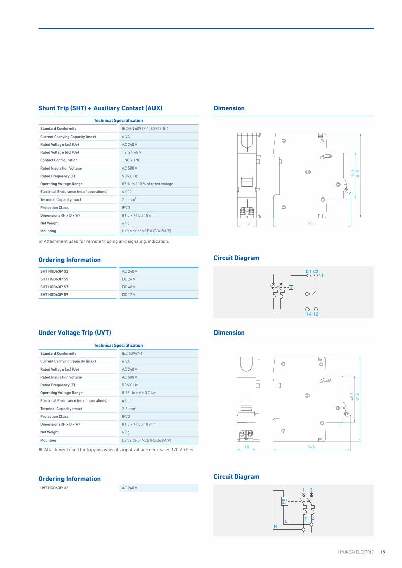
Shunt Trip (SHT) + Auxiliary Contact (AUX)
Under Voltage Trip (UVT)
Dimension
Dimension
Technical Specilification
Standard Conformity IEC/EN 60947-1, 60947-5-4
Current Carrying Capacity (max) 6 VA
Rated Voltage (ac) (Ue) AC 240 V
Rated Voltage (dc) (Ue) 12, 24, 48 V
Contact Configuration 1NO + 1NC
Rated Insulation Voltage AC 500 V
Rated Frequency (F) 50/60 Hz
Operating Voltage Range 85 % to 110 % of rated voltage
Electrical Endurance (no.of operations) 4,000
Terminal Capacity(max) 2.5 mm²
Protection Class IP20
Dimensions (H x D x W) 81.5 x 74.5 x 18 mm
Net Weight 64 g
Mounting Left side of MCB (HGD63M/P)
Ordering Information
SHT HGD63P S2 AC 240 V
SHT HGD63P S5 DC 24 V
SHT HGD63P S7 DC 48 V
SHT HGD63P S9 DC 12 V
Technical Specilification
Standard Conformity IEC 60947-1
Current Carrying Capacity (max) 6 VA
Rated Voltage (ac) (Ue) AC 240 V
Rated Insulation Voltage AC 500 V
Rated Frequency (F) 50/60 Hz
Operating Voltage Range 0.35 Ue ≥ V ≥ 0.7 Ue
Electrical Endurance (no.of operations) 4,000
Terminal Capacity (max) 2.5 mm²
Protection Class IP20
Dimensions (H x D x W) 81.5 x 74.5 x 18 mm
Net Weight 60 g
Mounting Left side of MCB (HGD63M/P)
Ordering InformationUVT HGD63P U2 AC 240 V
Circuit Diagram
Circuit Diagram
※ Attachment used for tripping when its input voltage decreases 170 V ±5 %
C2
12
11C1
14
74.5
45.3
81.5
18
74.5
45.3
81.5
8.8
74.5
45.3
81.5
8.8
74.5
45.3
81.5
18
74.5
45.3
81.5
8.8
74.5
45.3
81.5
8.8
※ Attachment used for remote tripping and signaling, indication.
U
1
2LN
3
4
U>>U<
16 HG Modular Devices
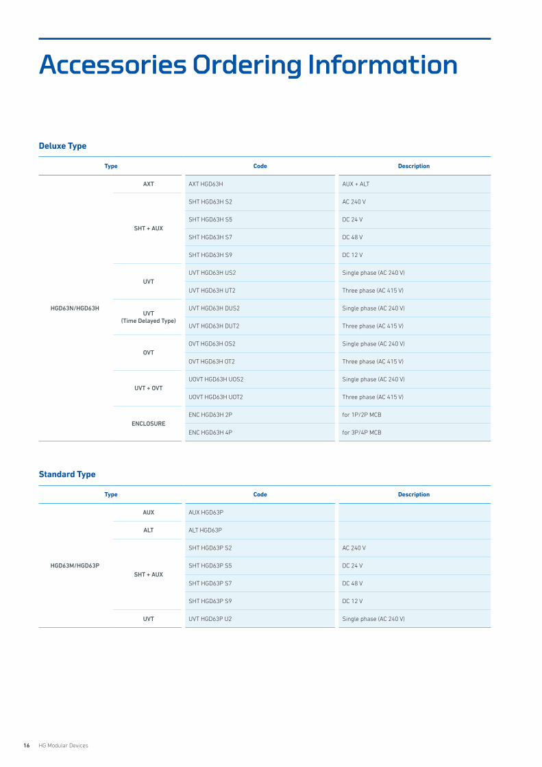
Accessories Ordering Information
Deluxe Type
Standard Type
Type Code Description
HGD63N/HGD63H
AXT AXT HGD63H AUX + ALT
SHT + AUX
SHT HGD63H S2 AC 240 V
SHT HGD63H S5 DC 24 V
SHT HGD63H S7 DC 48 V
SHT HGD63H S9 DC 12 V
UVTUVT HGD63H US2 Single phase (AC 240 V)
UVT HGD63H UT2 Three phase (AC 415 V)
UVT (Time Delayed Type)
UVT HGD63H DUS2 Single phase (AC 240 V)
UVT HGD63H DUT2 Three phase (AC 415 V)
OVTOVT HGD63H OS2 Single phase (AC 240 V)
OVT HGD63H OT2 Three phase (AC 415 V)
UVT + OVT UOVT HGD63H UOS2 Single phase (AC 240 V)
UOVT HGD63H UOT2 Three phase (AC 415 V)
ENCLOSUREENC HGD63H 2P for 1P/2P MCB
ENC HGD63H 4P for 3P/4P MCB
Type Code Description
HGD63M/HGD63P
AUX AUX HGD63P
ALT ALT HGD63P
SHT + AUX
SHT HGD63P S2 AC 240 V
SHT HGD63P S5 DC 24 V
SHT HGD63P S7 DC 48 V
SHT HGD63P S9 DC 12 V
UVT UVT HGD63P U2 Single phase (AC 240 V)
17HYUNDAI ELECTRIC
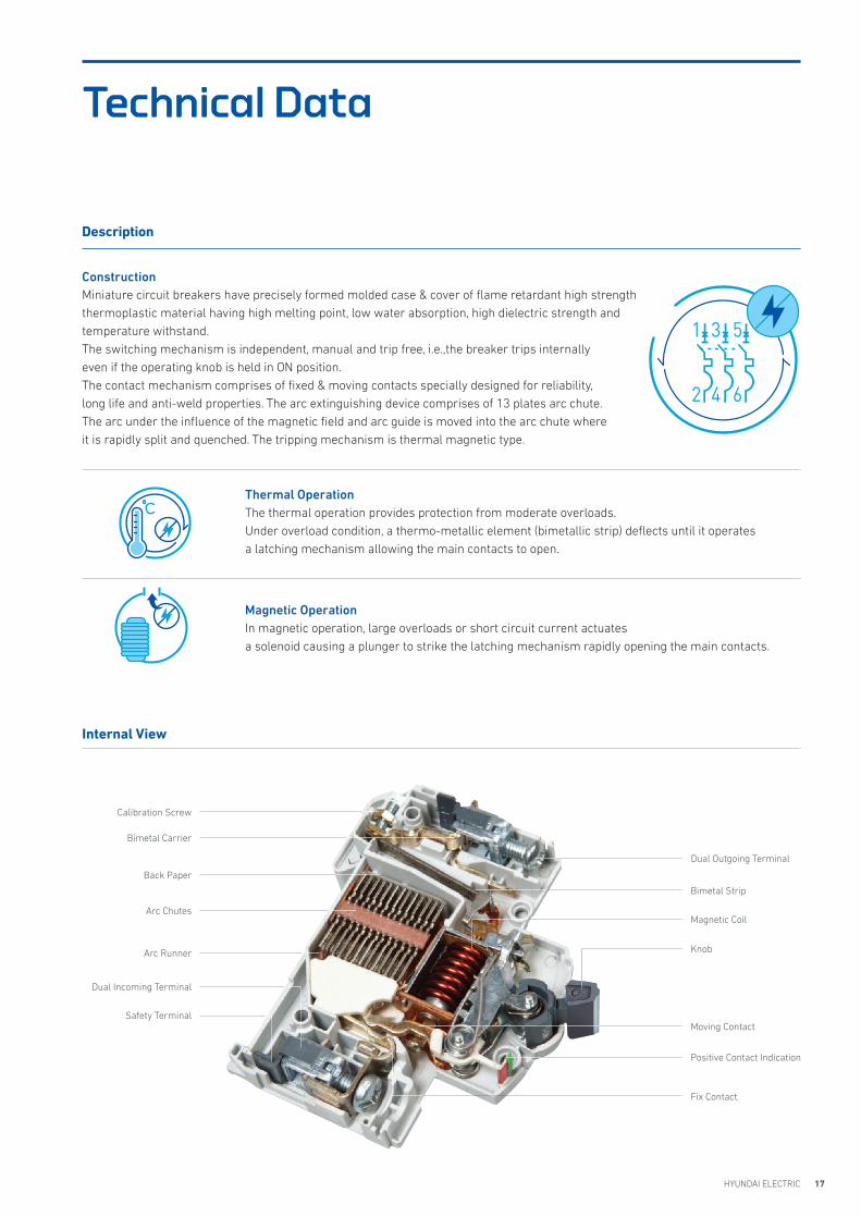
Calibration Screw
Dual Outgoing Terminal
Bimetal Carrier
Bimetal Strip
Back Paper
Magnetic CoilArc Chutes
KnobArc Runner
Moving Contact
Dual Incoming Terminal
Positive Contact Indication
Safety Terminal
Fix Contact
Internal View
Construction Miniature circuit breakers have precisely formed molded case & cover of flame retardant high strength thermoplastic material having high melting point, low water absorption, high dielectric strength and temperature withstand.The switching mechanism is independent, manual and trip free, i.e.,the breaker trips internally even if the operating knob is held in ON position.The contact mechanism comprises of fixed & moving contacts specially designed for reliability, long life and anti-weld properties. The arc extinguishing device comprises of 13 plates arc chute.The arc under the influence of the magnetic field and arc guide is moved into the arc chute where it is rapidly split and quenched. The tripping mechanism is thermal magnetic type.
Thermal OperationThe thermal operation provides protection from moderate overloads. Under overload condition, a thermo-metallic element (bimetallic strip) deflects until it operates a latching mechanism allowing the main contacts to open.
Magnetic OperationIn magnetic operation, large overloads or short circuit current actuates a solenoid causing a plunger to strike the latching mechanism rapidly opening the main contacts.
Technical Data
Description
18 HG Modular Devices
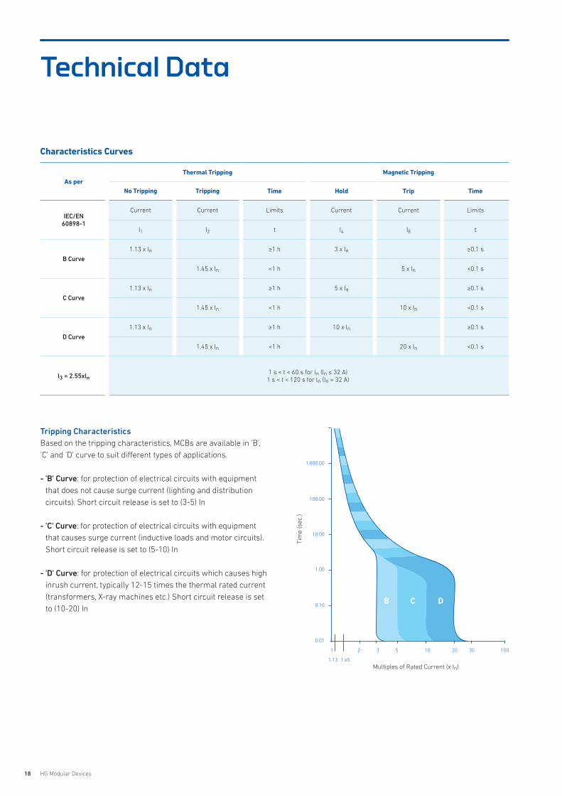
Characteristics Curves
As perThermal Tripping Magnetic Tripping
No Tripping Tripping Time Hold Trip Time
IEC/EN60898-1
Current Current Limits Current Current Limits
I1 I2 t I4 I5 t
B Curve
1.13 x In ≥1 h 3 x In ≥0.1 s
1.45 x In <1 h 5 x In <0.1 s
C Curve
1.13 x In ≥1 h 5 x In ≥0.1 s
1.45 x In <1 h 10 x In <0.1 s
D Curve
1.13 x In ≥1 h 10 x In ≥0.1 s
1.45 x In <1 h 20 x In <0.1 s
l3 = 2.55xln1 s < t < 60 s for ln (In ≤ 32 A)
1 s < t < 120 s for ln (In > 32 A)
1,000.00
100.00
10.00
1.00
0.10
0.01
1 2 3 5 10 20 30 100
1.13 1.45
Tim
e (s
ec.)
Multiples of Rated Current (x In)
B C D
Tripping CharacteristicsBased on the tripping characteristics, MCBs are available in 'B', 'C' and 'D' curve to suit different types of applications.
- 'B' Curve: for protection of electrical circuits with equipment that does not cause surge current (lighting and distribution circuits). Short circuit release is set to (3-5) In
- 'C' Curve: for protection of electrical circuits with equipment that causes surge current (inductive loads and motor circuits).Short circuit release is set to (5-10) In
- 'D' Curve: for protection of electrical circuits which causes high inrush current, typically 12-15 times the thermal rated current (transformers, X-ray machines etc.) Short circuit release is set to (10-20) In
Technical Data
19HYUNDAI ELECTRIC
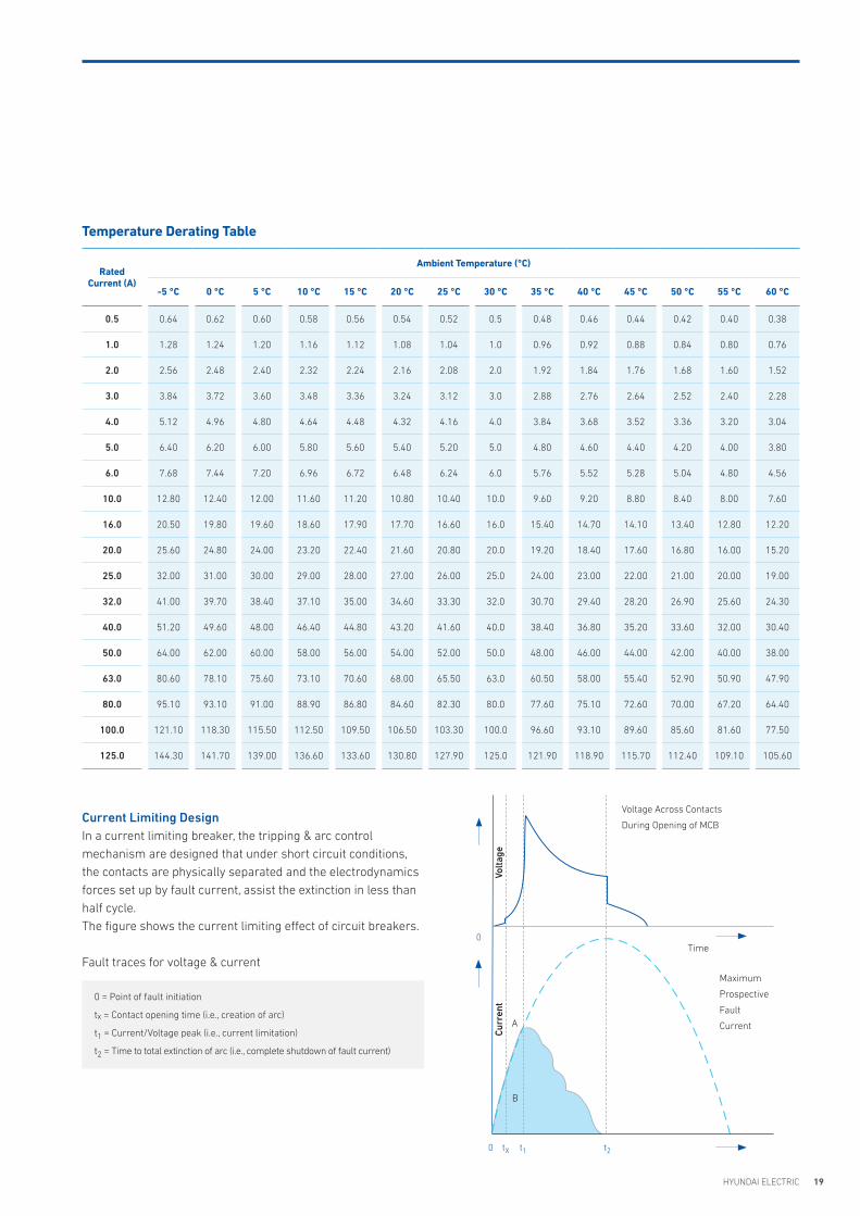
Temperature Derating Table
Volt
age
Voltage Across Contacts
During Opening of MCB
Maximum
Prospective
Fault
Current
Time
Curr
ent
A
B
0
0
tX t1 t2
Current Limiting DesignIn a current limiting breaker, the tripping & arc control mechanism are designed that under short circuit conditions, the contacts are physically separated and the electrodynamics forces set up by fault current, assist the extinction in less than half cycle.The figure shows the current limiting effect of circuit breakers.
Fault traces for voltage & current
0 = Point of fault initiation
tx = Contact opening time (i.e., creation of arc)
t1 = Current/Voltage peak (i.e., current limitation)
t2 = Time to total extinction of arc (i.e., complete shutdown of fault current)
RatedCurrent (A)
Ambient Temperature (°C)
-5 °C 0 °C 5 °C 10 °C 15 °C 20 °C 25 °C 30 °C 35 °C 40 °C 45 °C 50 °C 55 °C 60 °C
0.5 0.64 0.62 0.60 0.58 0.56 0.54 0.52 0.5 0.48 0.46 0.44 0.42 0.40 0.38
1.0 1.28 1.24 1.20 1.16 1.12 1.08 1.04 1.0 0.96 0.92 0.88 0.84 0.80 0.76
2.0 2.56 2.48 2.40 2.32 2.24 2.16 2.08 2.0 1.92 1.84 1.76 1.68 1.60 1.52
3.0 3.84 3.72 3.60 3.48 3.36 3.24 3.12 3.0 2.88 2.76 2.64 2.52 2.40 2.28
4.0 5.12 4.96 4.80 4.64 4.48 4.32 4.16 4.0 3.84 3.68 3.52 3.36 3.20 3.04
5.0 6.40 6.20 6.00 5.80 5.60 5.40 5.20 5.0 4.80 4.60 4.40 4.20 4.00 3.80
6.0 7.68 7.44 7.20 6.96 6.72 6.48 6.24 6.0 5.76 5.52 5.28 5.04 4.80 4.56
10.0 12.80 12.40 12.00 11.60 11.20 10.80 10.40 10.0 9.60 9.20 8.80 8.40 8.00 7.60
16.0 20.50 19.80 19.60 18.60 17.90 17.70 16.60 16.0 15.40 14.70 14.10 13.40 12.80 12.20
20.0 25.60 24.80 24.00 23.20 22.40 21.60 20.80 20.0 19.20 18.40 17.60 16.80 16.00 15.20
25.0 32.00 31.00 30.00 29.00 28.00 27.00 26.00 25.0 24.00 23.00 22.00 21.00 20.00 19.00
32.0 41.00 39.70 38.40 37.10 35.00 34.60 33.30 32.0 30.70 29.40 28.20 26.90 25.60 24.30
40.0 51.20 49.60 48.00 46.40 44.80 43.20 41.60 40.0 38.40 36.80 35.20 33.60 32.00 30.40
50.0 64.00 62.00 60.00 58.00 56.00 54.00 52.00 50.0 48.00 46.00 44.00 42.00 40.00 38.00
63.0 80.60 78.10 75.60 73.10 70.60 68.00 65.50 63.0 60.50 58.00 55.40 52.90 50.90 47.90
80.0 95.10 93.10 91.00 88.90 86.80 84.60 82.30 80.0 77.60 75.10 72.60 70.00 67.20 64.40
100.0 121.10 118.30 115.50 112.50 109.50 106.50 103.30 100.0 96.60 93.10 89.60 85.60 81.60 77.50
125.0 144.30 141.70 139.00 136.60 133.60 130.80 127.90 125.0 121.90 118.90 115.70 112.40 109.10 105.60
20 HG Modular Devices
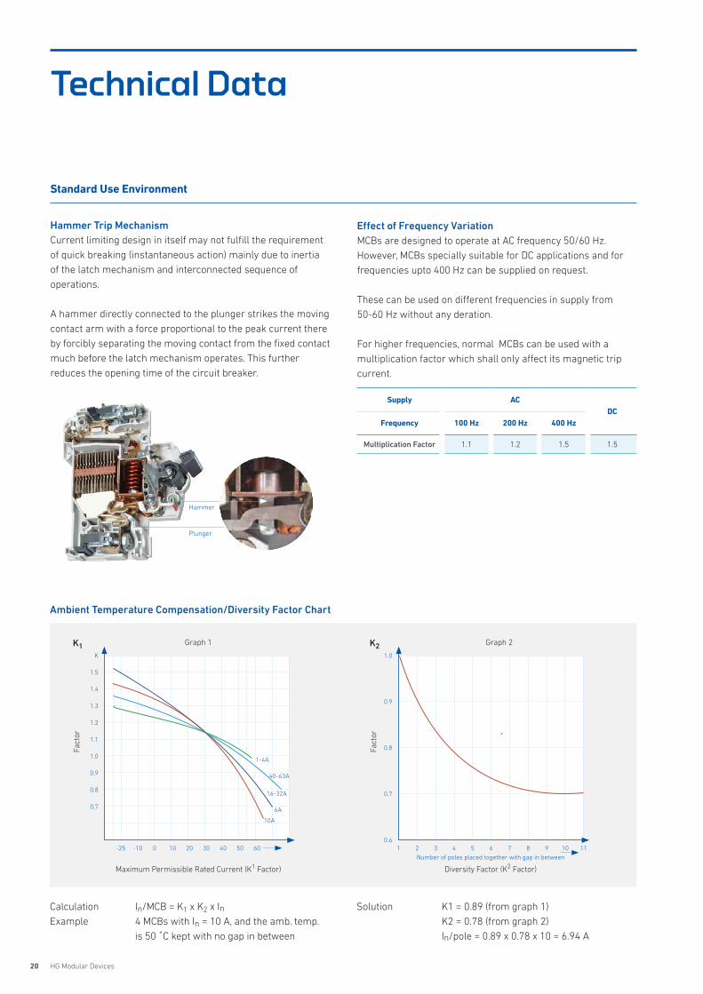
Hammer Trip MechanismCurrent limiting design in itself may not fulfill the requirement of quick breaking (instantaneous action) mainly due to inertia of the latch mechanism and interconnected sequence of operations.
A hammer directly connected to the plunger strikes the moving contact arm with a force proportional to the peak current there by forcibly separating the moving contact from the fixed contact much before the latch mechanism operates. This further reduces the opening time of the circuit breaker.
Effect of Frequency VariationMCBs are designed to operate at AC frequency 50/60 Hz. However, MCBs specially suitable for DC applications and for frequencies upto 400 Hz can be supplied on request.
These can be used on different frequencies in supply from 50-60 Hz without any deration.
For higher frequencies, normal MCBs can be used with a multiplication factor which shall only affect its magnetic trip current.
Ambient Temperature Compensation/Diversity Factor Chart
Calculation In/MCB = K1 x K2 x InExample 4 MCBs with In = 10 A, and the amb. temp.
is 50 �C kept with no gap in between
Solution K1 = 0.89 (from graph 1) K2 = 0.78 (from graph 2) In/pole = 0.89 x 0.78 x 10 = 6.94 A
Graph 1
K
1.5
1.4
1.3
1.2
1.1
1.0
0.9
0.8
0.7
-25 -10 0 10 20 30 40 50 60
Maximum Permissible Rated Current (K1 Factor)
Fact
or
K1
10A
6A
16-32A
40-63A
1-4A
Graph 2
1.0
0.9
0.8
0.7
0.61 2 3 4 5 6 7 8 9 10 11
Diversity Factor (K2 Factor)
Number of poles placed together with gap in between
Fact
or
K2
Supply ACDC
Frequency 100 Hz 200 Hz 400 Hz
Multiplication Factor 1.1 1.2 1.5 1.5
Hammer
Plunger
Standard Use Environment
Technical Data
21HYUNDAI ELECTRIC
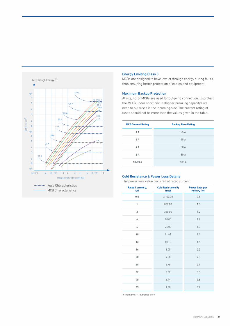
Let Through Energy I2t
Let T
hrou
gh I2 t
Prospective Fault Current (kA)
105
9
6
4
3
2
1.5
104
8
6
4
3
2
1.5
103
1.5104864321034x10⁵ 1.5865
Fuse CharacteristicsMCB Characteristics
25 A
35 A
2 A
4 A
32 A25 A20 A
16 A
10 A6 A
40 A/63 A
50 A
63 A
80 A
100 A
125 A
160 A
Energy Limiting Class 3MCBs are designed to have low let through energy during faults, thus ensuring better protection of cables and equipment.
Maximum Backup ProtectionAt site, no. of MCBs are used for outgoing connection. To protect the MCBs under short circuit (higher breaking capacity), we need to put fuses in the incoming side. The current rating of fuses should not be more than the values given in the table.
MCB Current Rating Backup Fuse Rating
1 A 25 A
2 A 35 A
4 A 50 A
6 A 80 A
10-63 A 100 A
Cold Resistance & Power Loss DetailsThe power loss value declared at rated current.
Rated Current In (A)
Cold Resistance RI(mΩ)
Power Loss perPole Pv (W)
0.5 3,100.00 0.8
1 860.80 1.0
2 280.00 1.2
4 70.00 1.2
6 25.00 1.3
10 11.68 1.4
13 10.10 1.6
16 8.00 2.2
20 4.50 2.3
25 3.78 3.1
32 2.57 3.3
40 1.94 3.6
63 1.30 6.2
※ Remarks: - Tolerance ±5 %
22 HG Modular Devices
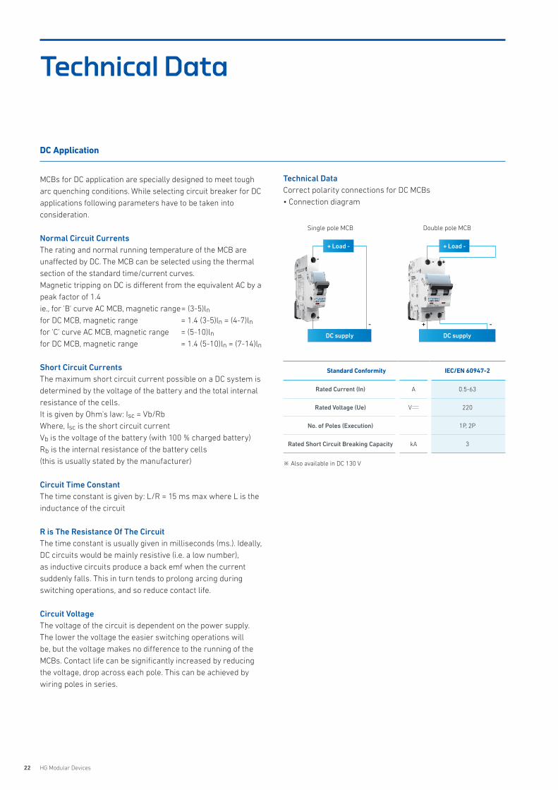
Technical DataCorrect polarity connections for DC MCBs• Connection diagram
Standard Conformity IEC/EN 60947-2
Rated Current (In) A 0.5-63
Rated Voltage (Ue) V 220
No. of Poles (Execution) 1P, 2P
Rated Short Circuit Breaking Capacity kA 3
MCBs for DC application are specially designed to meet tough arc quenching conditions. While selecting circuit breaker for DC applications following parameters have to be taken intoconsideration.
Normal Circuit CurrentsThe rating and normal running temperature of the MCB are unaffected by DC. The MCB can be selected using the thermal section of the standard time/current curves.Magnetic tripping on DC is different from the equivalent AC by a peak factor of 1.4ie., for 'B' curve AC MCB, magnetic range = (3-5)lnfor DC MCB, magnetic range = 1.4 (3-5)ln = (4-7)lnfor 'C' curve AC MCB, magnetic range = (5-10)lnfor DC MCB, magnetic range = 1.4 (5-10)ln = (7-14)ln
Short Circuit CurrentsThe maximum short circuit current possible on a DC system isdetermined by the voltage of the battery and the total internalresistance of the cells.It is given by Ohm's Iaw: Isc = Vb/RbWhere, Isc is the short circuit currentVb is the voltage of the battery (with 100 % charged battery)Rb is the internal resistance of the battery cells(this is usually stated by the manufacturer)
Circuit Time ConstantThe time constant is given by: L/R = 15 ms max where L is the inductance of the circuit
R is The Resistance Of The CircuitThe time constant is usually given in milliseconds (ms.). Ideally, DC circuits would be mainly resistive (i.e. a low number), as inductive circuits produce a back emf when the current suddenly falls. This in turn tends to prolong arcing during switching operations, and so reduce contact life.
Circuit VoltageThe voltage of the circuit is dependent on the power supply. The lower the voltage the easier switching operations will be, but the voltage makes no difference to the running of the MCBs. Contact life can be significantly increased by reducing the voltage, drop across each pole. This can be achieved by wiring poles in series.
※ Also available in DC 130 V
DC Application
Single pole MCB Double pole MCB
+ Load -
+
-
-
DC supply
+ Load -
+
+
+
-
-
-
DC supply
Technical Data
23HYUNDAI ELECTRIC
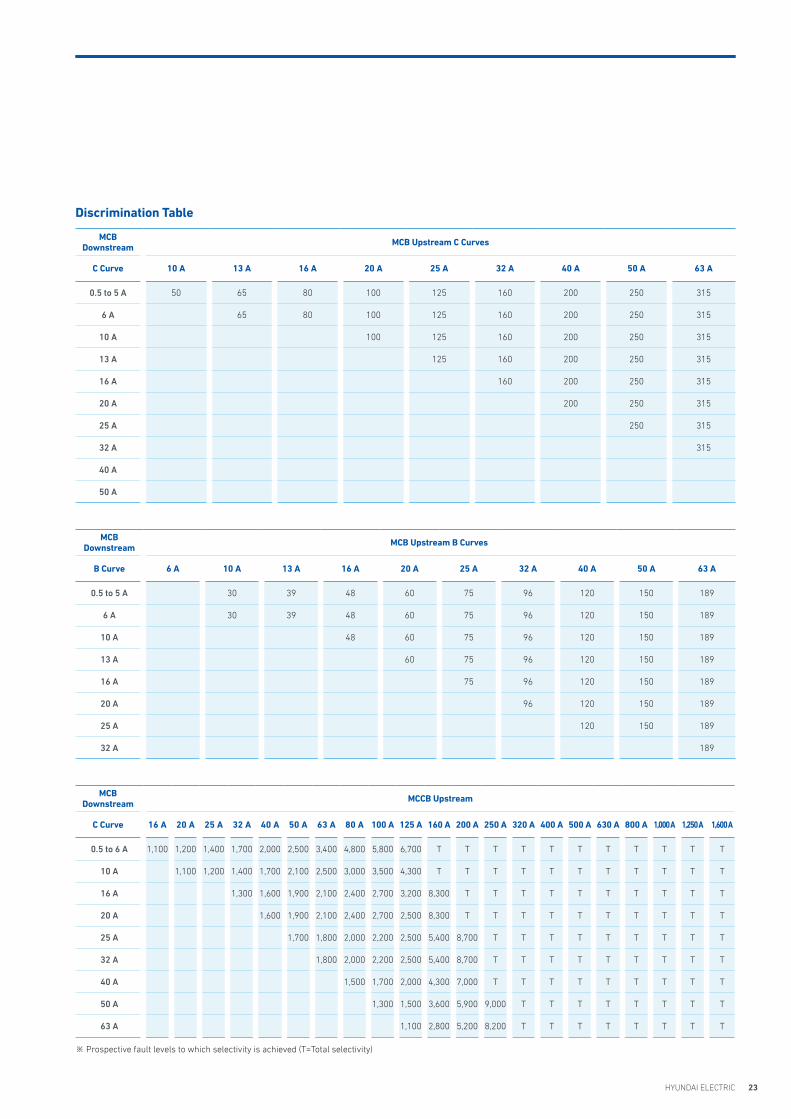
MCB Downstream MCB Upstream C Curves
C Curve 10 A 13 A 16 A 20 A 25 A 32 A 40 A 50 A 63 A
0.5 to 5 A 50 65 80 100 125 160 200 250 315
6 A 65 80 100 125 160 200 250 315
10 A 100 125 160 200 250 315
13 A 125 160 200 250 315
16 A 160 200 250 315
20 A 200 250 315
25 A 250 315
32 A 315
40 A
50 A
MCB Downstream MCB Upstream B Curves
B Curve 6 A 10 A 13 A 16 A 20 A 25 A 32 A 40 A 50 A 63 A
0.5 to 5 A 30 39 48 60 75 96 120 150 189
6 A 30 39 48 60 75 96 120 150 189
10 A 48 60 75 96 120 150 189
13 A 60 75 96 120 150 189
16 A 75 96 120 150 189
20 A 96 120 150 189
25 A 120 150 189
32 A 189
MCB Downstream MCCB Upstream
C Curve 16 A 20 A 25 A 32 A 40 A 50 A 63 A 80 A 100 A 125 A 160 A 200 A 250 A 320 A 400 A 500 A 630 A 800 A 1,000 A 1,250 A 1,600 A
0.5 to 6 A 1,100 1,200 1,400 1,700 2,000 2,500 3,400 4,800 5,800 6,700 T T T T T T T T T T T
10 A 1,100 1,200 1,400 1,700 2,100 2,500 3,000 3,500 4,300 T T T T T T T T T T T
16 A 1,300 1,600 1,900 2,100 2,400 2,700 3,200 8,300 T T T T T T T T T T
20 A 1,600 1,900 2,100 2,400 2,700 2,500 8,300 T T T T T T T T T T
25 A 1,700 1,800 2,000 2,200 2,500 5,400 8,700 T T T T T T T T T
32 A 1,800 2,000 2,200 2,500 5,400 8,700 T T T T T T T T T
40 A 1,500 1,700 2,000 4,300 7,000 T T T T T T T T T
50 A 1,300 1,500 3,600 5,900 9,000 T T T T T T T T
63 A 1,100 2,800 5,200 8,200 T T T T T T T T
Discrimination Table
※ Prospective fault levels to which selectivity is achieved (T=Total selectivity)
24 HG Modular Devices
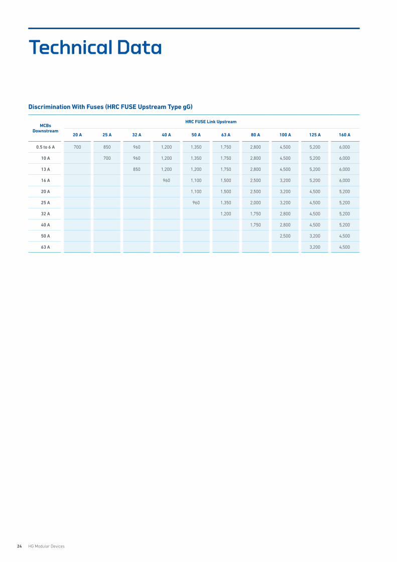
MCBs Downstream
HRC FUSE Link Upstream
20 A 25 A 32 A 40 A 50 A 63 A 80 A 100 A 125 A 160 A
0.5 to 6 A 700 850 960 1,200 1,350 1,750 2,800 4,500 5,200 6,000
10 A 700 960 1,200 1,350 1,750 2,800 4,500 5,200 6,000
13 A 850 1,200 1,200 1,750 2,800 4,500 5,200 6,000
16 A 960 1,100 1,500 2,500 3,200 5,200 6,000
20 A 1,100 1,500 2,500 3,200 4,500 5,200
25 A 960 1,350 2,000 3,200 4,500 5,200
32 A 1,200 1,750 2,800 4,500 5,200
40 A 1,750 2,800 4,500 5,200
50 A 2,500 3,200 4,500
63 A 3,200 4,500
Discrimination With Fuses (HRC FUSE Upstream Type gG)
Technical Data
25HYUNDAI ELECTRIC
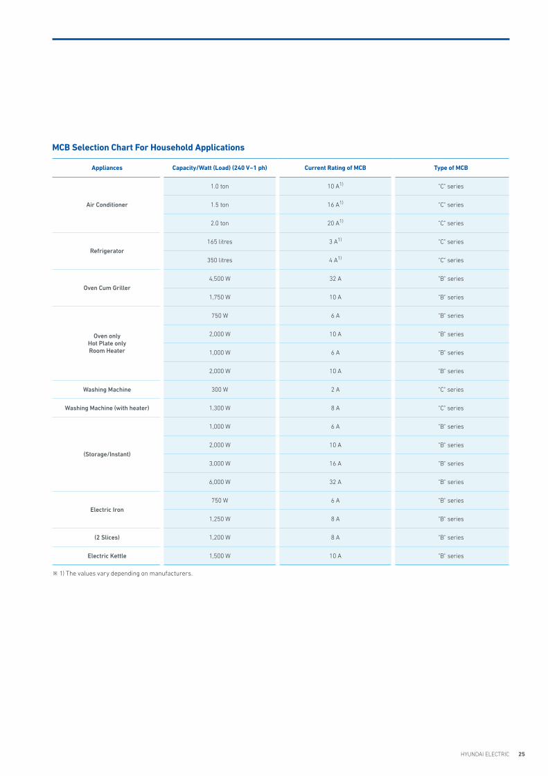
MCB Selection Chart For Household Applications
Appliances Capacity/Watt (Load) (240 V~1 ph) Current Rating of MCB Type of MCB
Air Conditioner
1.0 ton 10 A1) "C" series
1.5 ton 16 A1) "C" series
2.0 ton 20 A1) "C" series
Refrigerator165 litres 3 A1) "C" series
350 litres 4 A1) "C" series
Oven Cum Griller4,500 W 32 A "B" series
1,750 W 10 A "B" series
Oven onlyHot Plate onlyRoom Heater
750 W 6 A "B" series
2,000 W 10 A "B" series
1,000 W 6 A "B" series
2,000 W 10 A "B" series
Washing Machine 300 W 2 A "C" series
Washing Machine (with heater) 1,300 W 8 A "C" series
(Storage/Instant)
1,000 W 6 A "B" series
2,000 W 10 A "B" series
3,000 W 16 A "B" series
6,000 W 32 A "B" series
Electric Iron750 W 6 A "B" series
1,250 W 8 A "B" series
(2 Slices) 1,200 W 8 A "B" series
Electric Kettle 1,500 W 10 A "B" series
※ 1) The values vary depending on manufacturers.
26 HG Modular Devices
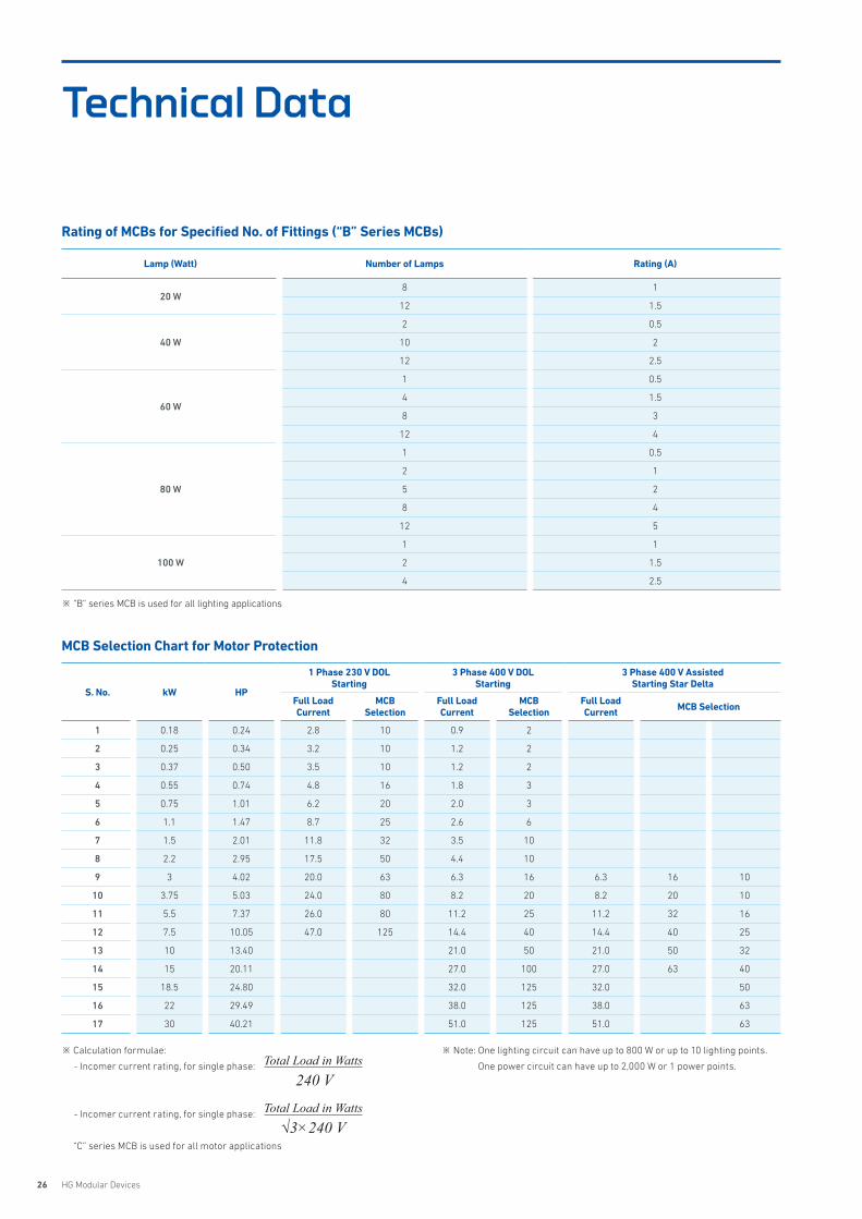
Lamp (Watt) Number of Lamps Rating (A)
20 W8 1
12 1.5
40 W
2 0.5
10 2
12 2.5
60 W
1 0.5
4 1.5
8 3
12 4
80 W
1 0.5
2 1
5 2
8 4
12 5
100 W
1 1
2 1.5
4 2.5
S. No. kW HP
1 Phase 230 V DOLStarting
3 Phase 400 V DOLStarting
3 Phase 400 V Assisted Starting Star Delta
Full LoadCurrent
MCBSelection
Full LoadCurrent
MCBSelection
Full LoadCurrent MCB Selection
1 0.18 0.24 2.8 10 0.9 2
2 0.25 0.34 3.2 10 1.2 2
3 0.37 0.50 3.5 10 1.2 2
4 0.55 0.74 4.8 16 1.8 3
5 0.75 1.01 6.2 20 2.0 3
6 1.1 1.47 8.7 25 2.6 6
7 1.5 2.01 11.8 32 3.5 10
8 2.2 2.95 17.5 50 4.4 10
9 3 4.02 20.0 63 6.3 16 6.3 16 10
10 3.75 5.03 24.0 80 8.2 20 8.2 20 10
11 5.5 7.37 26.0 80 11.2 25 11.2 32 16
12 7.5 10.05 47.0 125 14.4 40 14.4 40 25
13 10 13.40 21.0 50 21.0 50 32
14 15 20.11 27.0 100 27.0 63 40
15 18.5 24.80 32.0 125 32.0 50
16 22 29.49 38.0 125 38.0 63
17 30 40.21 51.0 125 51.0 63
Rating of MCBs for Specified No. of Fittings (“B” Series MCBs)
MCB Selection Chart for Motor Protection
※ “B” series MCB is used for all lighting applications
※ Calculation formulae:
- Incomer current rating, for single phase:
- Incomer current rating, for single phase:
“C” series MCB is used for all motor applications
※ Note: One lighting circuit can have up to 800 W or up to 10 lighting points.
One power circuit can have up to 2,000 W or 1 power points.Total Load in Watts240 V
Total Load in Watts√3×240 V
Technical Data
27HYUNDAI ELECTRIC
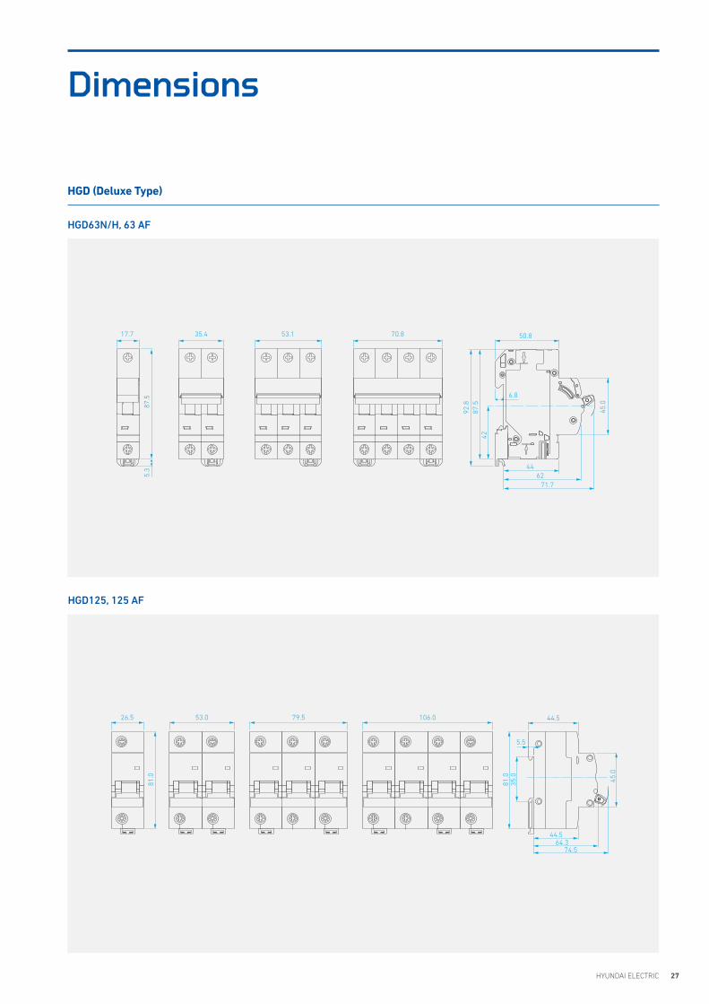
Dimensions
HGD125, 125 AF
50.8
92.8
87.5
42
5.3
87.5 6.8
70.853.135.417.7
4462
71.7
45.0
44.564.3
74.5
81.0
81.0
35.0
45.0
26.5 53.0 79.5 106.0 44.5
5.5
HGD (Deluxe Type)
HGD63N/H, 63 AF
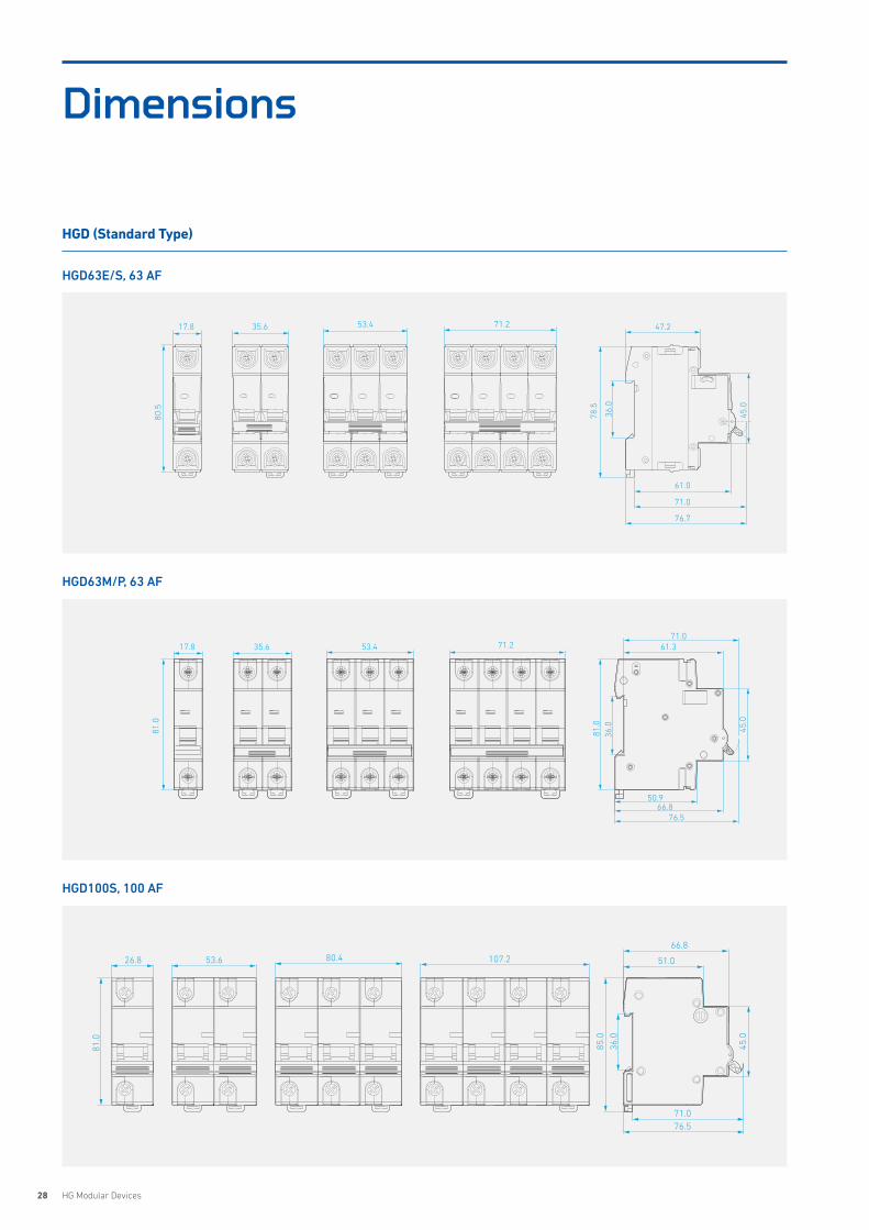
28 HG Modular Devices
HGD63M/P, 63 AF
HGD100S, 100 AF
35.6 53.4 71.2 47.2
45.0
71.0
61.0
76.7
36.0
78.5
17.8
80.5
17.8 35.6 53.4 71.2
36.0
81.0
61.371.0
50.966.8
45.0
76.5
81.0
26.8 53.6 80.4 107.2
66.8
51.0
45.0
36.0
85.0
81.0
76.571.0
HGD (Standard Type)
HGD63E/S, 63 AF
Dimensions
29HYUNDAI ELECTRIC
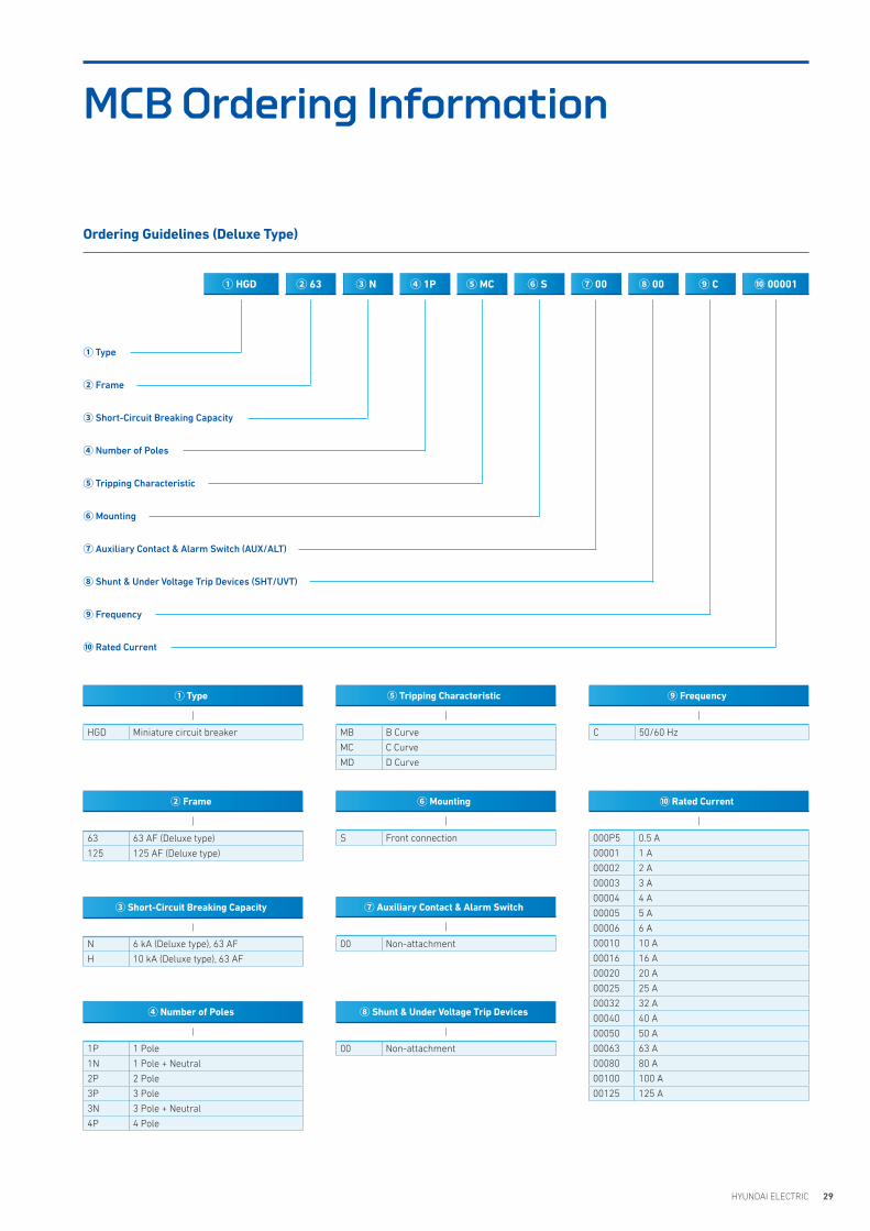
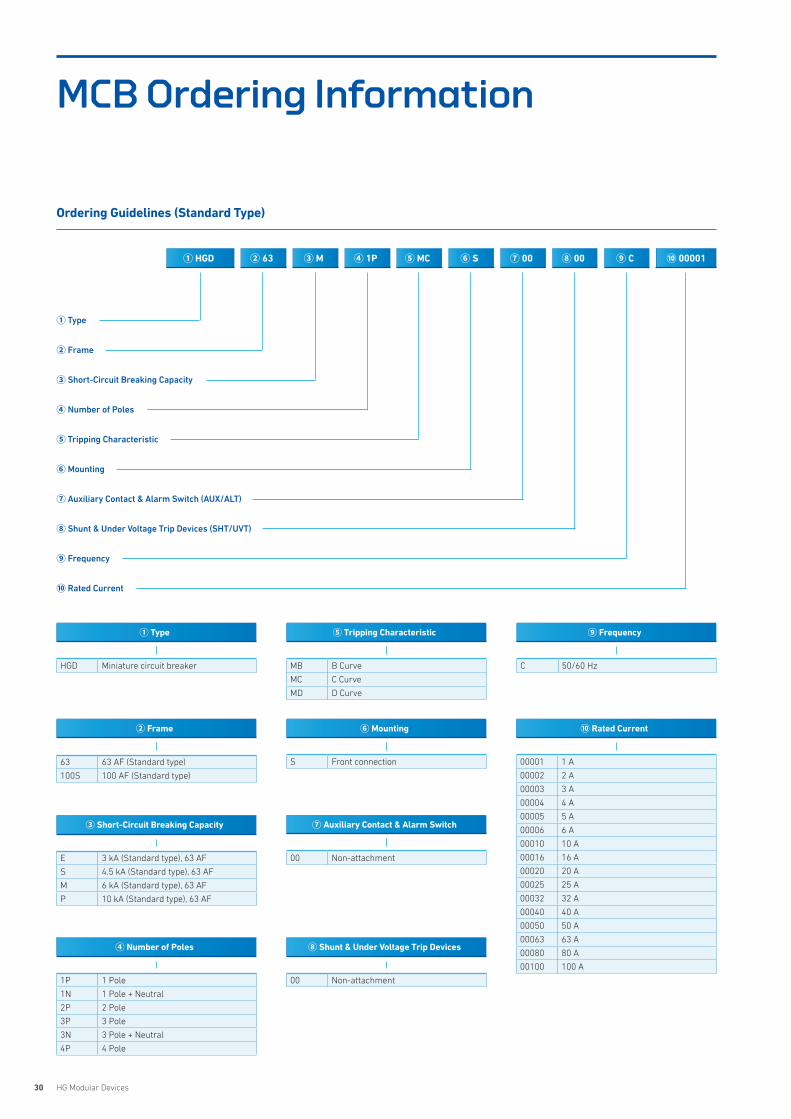
MCB Ordering Information
② Frame
63 63 AF (Deluxe type)
125 125 AF (Deluxe type)
C 50/60 Hz
⑨ Frequency
000P5 0.5 A
00001 1 A
00002 2 A
00003 3 A
00004 4 A
00005 5 A
00006 6 A
00010 10 A
00016 16 A
00020 20 A
00025 25 A
00032 32 A
00040 40 A
00050 50 A
00063 63 A
00080 80 A
00100 100 A
00125 125 A
⑩ Rated Current
S Front connection
⑥ Mounting
00 Non-attachment
⑧ Shunt & Under Voltage Trip Devices
00 Non-attachment
⑦ Auxiliary Contact & Alarm Switch
① Type
HGD Miniature circuit breaker
③ Short-Circuit Breaking Capacity
N 6 kA (Deluxe type), 63 AF
H 10 kA (Deluxe type), 63 AF
④ Number of Poles
1P 1 Pole
1N 1 Pole + Neutral
2P 2 Pole
3P 3 Pole
3N 3 Pole + Neutral
4P 4 Pole
MB B Curve
MC C Curve
MD D Curve
⑤ Tripping Characteristic
① HGD ② 63 ③ N ④ 1P ⑥ S⑤ MC ⑦ 00 ⑧ 00 ⑨ C ⑩ 00001
Ordering Guidelines (Deluxe Type)
① Type
② Frame
③ Short-Circuit Breaking Capacity
④ Number of Poles
⑤ Tripping Characteristic
⑥ Mounting
⑦ Auxiliary Contact & Alarm Switch (AUX/ALT)
⑧ Shunt & Under Voltage Trip Devices (SHT/UVT)
⑨ Frequency
⑩ Rated Current
30 HG Modular Devices
MCB Ordering Information
② Frame
63 63 AF (Standard type)
100S 100 AF (Standard type)
C 50/60 Hz
⑨ Frequency
00001 1 A
00002 2 A
00003 3 A
00004 4 A
00005 5 A
00006 6 A
00010 10 A
00016 16 A
00020 20 A
00025 25 A
00032 32 A
00040 40 A
00050 50 A
00063 63 A
00080 80 A
00100 100 A
⑩ Rated Current
S Front connection
⑥ Mounting
00 Non-attachment
⑧ Shunt & Under Voltage Trip Devices
00 Non-attachment
⑦ Auxiliary Contact & Alarm Switch
① Type
HGD Miniature circuit breaker
③ Short-Circuit Breaking Capacity
E 3 kA (Standard type), 63 AF
S 4.5 kA (Standard type), 63 AF
M 6 kA (Standard type), 63 AF
P 10 kA (Standard type), 63 AF
④ Number of Poles
1P 1 Pole
1N 1 Pole + Neutral
2P 2 Pole
3P 3 Pole
3N 3 Pole + Neutral
4P 4 Pole
MB B Curve
MC C Curve
MD D Curve
⑤ Tripping Characteristic
Ordering Guidelines (Standard Type)
① Type
② Frame
③ Short-Circuit Breaking Capacity
④ Number of Poles
⑤ Tripping Characteristic
⑥ Mounting
⑦ Auxiliary Contact & Alarm Switch (AUX/ALT)
⑧ Shunt & Under Voltage Trip Devices (SHT/UVT)
⑨ Frequency
⑩ Rated Current
① HGD ② 63 ③ M ④ 1P ⑥ S⑤ MC ⑦ 00 ⑧ 00 ⑨ C ⑩ 00001
31HYUNDAI ELECTRIC
Features 32
Selection Table 34
Accessories 36
Technical Data 38
Dimensions 43
Order Information 45
HRCResidual Current Circuit Breaker

32 HG Modular Devices
Features
HRC Residual Current Circuit Breaker
RCCB (also popularly known as ELCB) is a mechanical switching device designed to make, carry and break currents under
normal service conditions and to cause the opening of the contacts when the leakage current attains a given value under
specified conditions. Hyundai offers a wide range of RCCBs for protecting human life against fatal electric shocks as well as for
providing protection against fire caused by earth faults.
HRC63 HRC100
HRC Deluxe Type
33HYUNDAI ELECTRIC
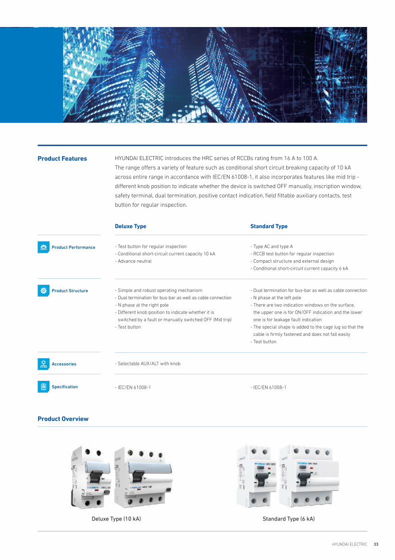
HYUNDAI ELECTRIC introduces the HRC series of RCCBs rating from 16 A to 100 A.
The range offers a variety of feature such as conditional short circuit breaking capacity of 10 kA
across entire range in accordance with IEC/EN 61008-1, it also incorporates features like mid trip -
different knob position to indicate whether the device is switched OFF manually, inscription window,
safety terminal, dual termination, positive contact indication, field fittable auxiliary contacts, test
button for regular inspection.
Product Features
Product Overview
Deluxe Type (10 kA) Standard Type (6 kA)
Deluxe Type
- Test button for regular inspection
- Conditional short-circuit current capacity 10 kA
- Advance neutral
- Simple and robust operating mechanism
- Dual termination for bus-bar as well as cable connection
- N phase at the right pole
- Different knob position to indicate whether it is
switched by a fault or manually switched OFF (Mid trip)
- Test button
- Selectable AUX/ALT with knob
- IEC/EN 61008-1
Standard Type
- Type AC and type A
- RCCB test button for regular inspection
- Compact structure and external design
- Conditional short-circuit current capacity 6 kA
- Dual termination for bus-bar as well as cable connection
- N phase at the left pole
- There are two indication windows on the surface,
the upper one is for ON/OFF indication and the lower
one is for leakage fault indication
- The special shape is added to the cage lug so that the
cable is firmly fastened and does not fall easily
- Test button
- IEC/EN 61008-1
Product Performance
Product Structure
Accessories
Specification

34 HG Modular Devices
Model HRC63, 63 AF HRC100, 100 AF
Reference Standard IEC/EN 61008-1 IEC/EN 61008-1
No. of Poles 2P (1P + N), 4P (3P + N) 2P (1P + N), 4P (3P + N)
Rated Current (In) 16, 25, 40, 50, 63 A 80, 100 A
Rated Voltage (Ue) AC 240/415 V AC 240/415 V
Rated Frequency (F) 50/60 Hz 50/60 Hz
Rated Conditional Short Circuit Current (Inc) 10 kA 10 kA
Rated Residual Operating Current (I⊿c) 30, 100, 300 30, 100, 300
Rated Making Breaking Capacity (lm) 630 A or 10 ln whichever is greater 630 A or 10 In whichever is greater
Operating Characteristics in Presence of Residual Current with d.c Components 'A' type & 'AC' type 'A' type & 'AC' type
Trip Time 1 IΔn < 300 ms, 5 IΔn < 40 ms 1 IΔn < 300 ms, 5 IΔn < 40 ms
Rated Insulation Voltage (Ui) 500 V 500 V
Rated Impulse Voltage (Uimp) 4 kV 4 kV
Dielectric Strength 2.5 kV 2.5 kV
Electrical/Mechanical Endurance(no. of operations) Minimum 10,000/20,000 10,000/20,000
Operating Temperature -25 °C to + 55 °C -25 °C to + 55 °C
Humidity 95 % RH 95 % RH
Terminal Capacity (max) 35 mm2 50 mm2
Tightening Torque 2 N·m 2.5 N·m
Vibration 3 g 3 g
Shock Resistance 40 mm free fall 40 mm free fall
Protection Class IP20 IP20
Positive Contact Indication Red-ON, Green-OFF Red-ON, Green-OFF
Net Weight in kg 0.215 kg (for 2P) ; 0.335 kg (for 4P) 0.230 kg (for 2P) ; 0.404 kg (for 4P)
Dimensions (H x D x W)/Pole in mm 87.5 x 71.7 x 35.9 mm (for 2P) ; 87.5 x 71.7 x 72.0 mm (for 4P) 88.2 x 71.7 x 35.9 mm (for 2P) ; 88.2 x 71.7 x 72.0 mm (for 4P)
Mounting Clip on DIN Rail (35 mm x 7.5 mm) Clip on DIN Rail (35 mm x 7.5 mm)
Installation Position Vertical/Horizontal Vertical/Horizontal
Case & Cover Molded, flame retardant thermoplastic material Molded, flame retardant thermoplastic material
Busbar Connections Pin/Fork type Pin/Fork type
Auxiliary Contacts Yes No
HRC (Deluxe Type)
Selection Table
35HYUNDAI ELECTRIC
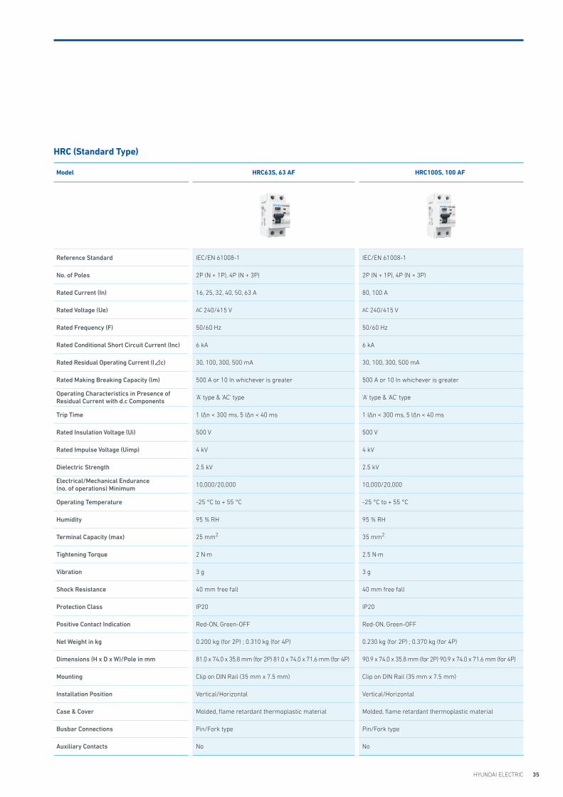
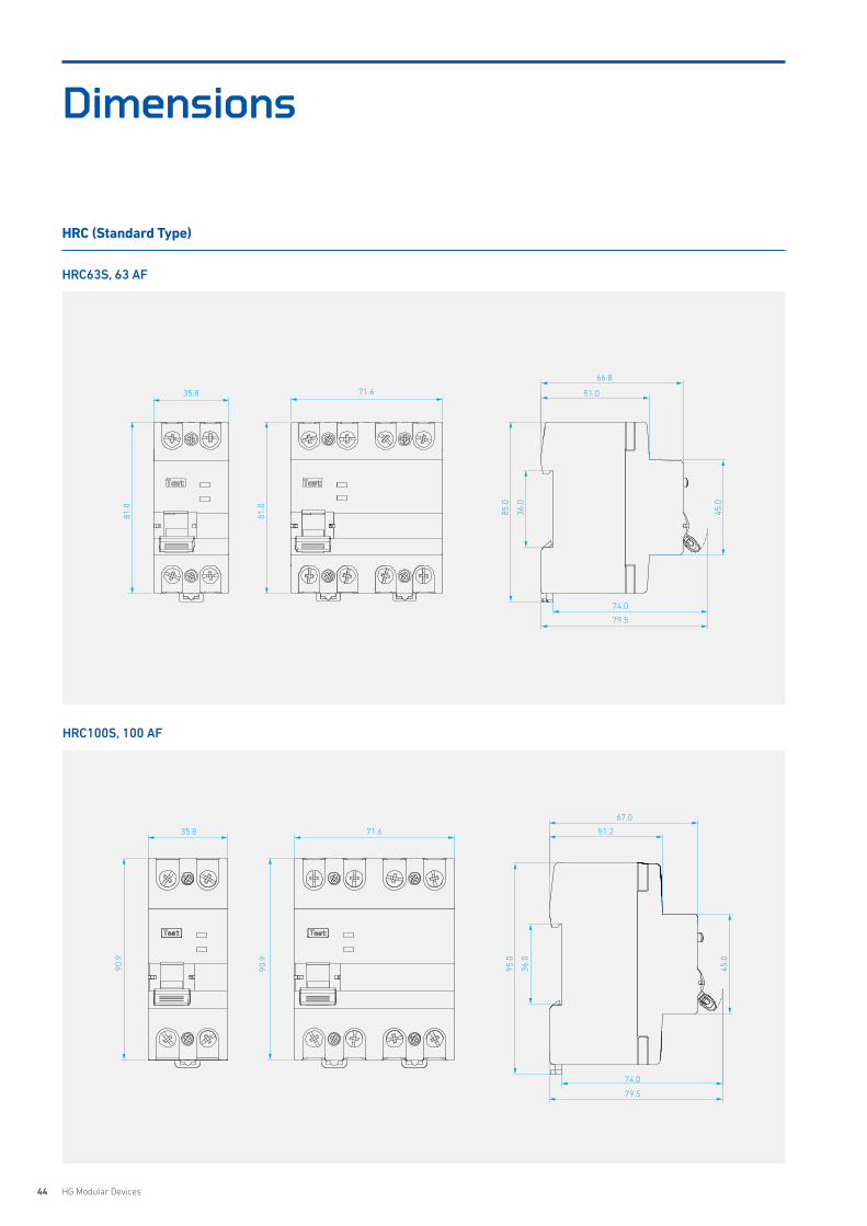
Model HRC63S, 63 AF HRC100S, 100 AF
Reference Standard IEC/EN 61008-1 IEC/EN 61008-1
No. of Poles 2P (N + 1P), 4P (N + 3P) 2P (N + 1P), 4P (N + 3P)
Rated Current (In) 16, 25, 32, 40, 50, 63 A 80, 100 A
Rated Voltage (Ue) AC 240/415 V AC 240/415 V
Rated Frequency (F) 50/60 Hz 50/60 Hz
Rated Conditional Short Circuit Current (Inc) 6 kA 6 kA
Rated Residual Operating Current (I⊿c) 30, 100, 300, 500 mA 30, 100, 300, 500 mA
Rated Making Breaking Capacity (lm) 500 A or 10 In whichever is greater 500 A or 10 In whichever is greater
Operating Characteristics in Presence of Residual Current with d.c Components 'A' type & 'AC' type 'A' type & 'AC' type
Trip Time 1 IΔn < 300 ms, 5 IΔn < 40 ms 1 IΔn < 300 ms, 5 IΔn < 40 ms
Rated Insulation Voltage (Ui) 500 V 500 V
Rated Impulse Voltage (Uimp) 4 kV 4 kV
Dielectric Strength 2.5 kV 2.5 kV
Electrical/Mechanical Endurance(no. of operations) Minimum 10,000/20,000 10,000/20,000
Operating Temperature -25 °C to + 55 °C -25 °C to + 55 °C
Humidity 95 % RH 95 % RH
Terminal Capacity (max) 25 mm2 35 mm2
Tightening Torque 2 N·m 2.5 N·m
Vibration 3 g 3 g
Shock Resistance 40 mm free fall 40 mm free fall
Protection Class IP20 IP20
Positive Contact Indication Red-ON, Green-OFF Red-ON, Green-OFF
Net Weight in kg 0.200 kg (for 2P) ; 0.310 kg (for 4P) 0.230 kg (for 2P) ; 0.370 kg (for 4P)
Dimensions (H x D x W)/Pole in mm 81.0 x 74.0 x 35.8 mm (for 2P) 81.0 x 74.0 x 71.6 mm (for 4P) 90.9 x 74.0 x 35.8 mm (for 2P) 90.9 x 74.0 x 71.6 mm (for 4P)
Mounting Clip on DIN Rail (35 mm x 7.5 mm) Clip on DIN Rail (35 mm x 7.5 mm)
Installation Position Vertical/Horizontal Vertical/Horizontal
Case & Cover Molded, flame retardant thermoplastic material Molded, flame retardant thermoplastic material
Busbar Connections Pin/Fork type Pin/Fork type
Auxiliary Contacts No No
HRC (Standard Type)
36 HG Modular Devices
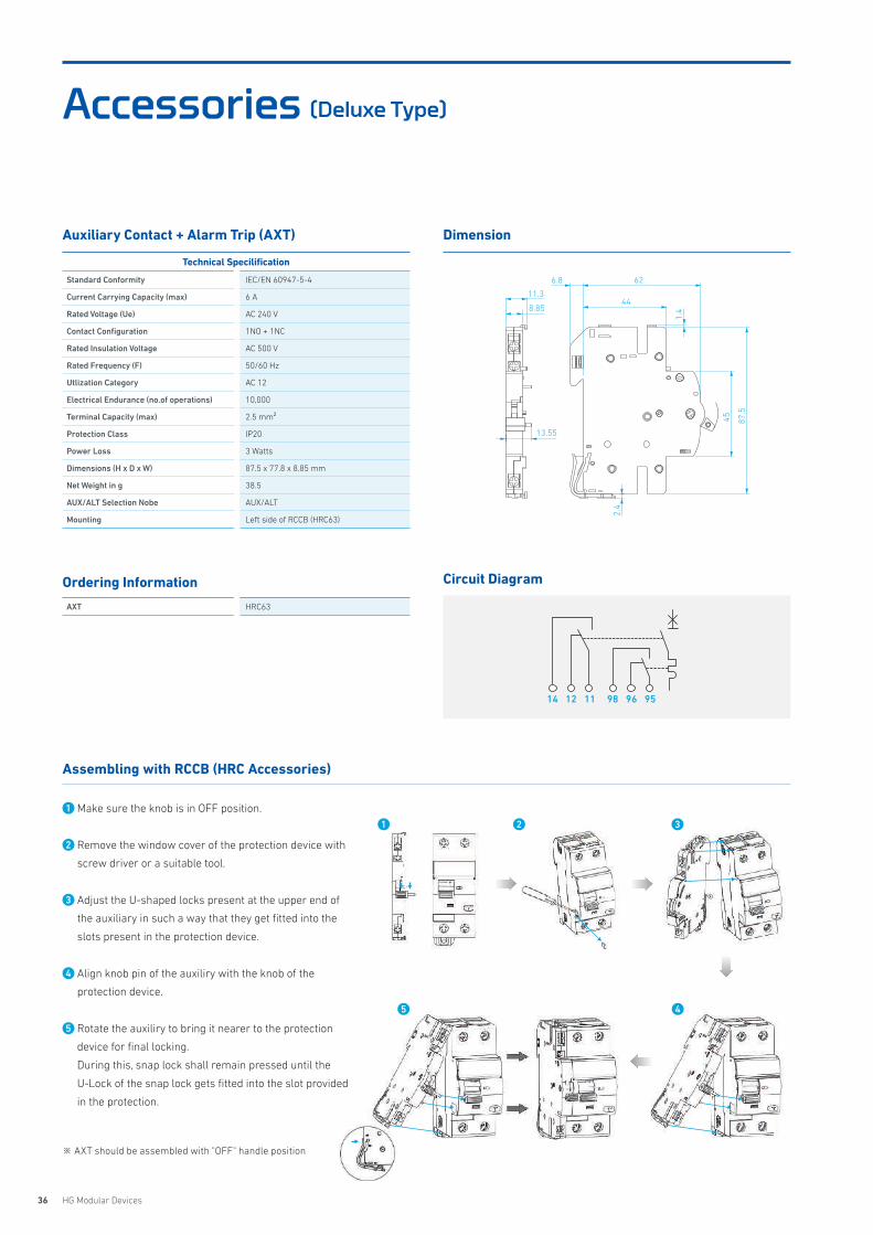
Accessories (Deluxe Type)
Auxiliary Contact + Alarm Trip (AXT) Dimension
Circuit Diagram
Technical Specilification
Standard Conformity IEC/EN 60947-5-4
Current Carrying Capacity (max) 6 A
Rated Voltage (Ue) AC 240 V
Contact Configuration 1NO + 1NC
Rated Insulation Voltage AC 500 V
Rated Frequency (F) 50/60 Hz
Utlization Category AC 12
Electrical Endurance (no.of operations) 10,000
Terminal Capacity (max) 2.5 mm²
Protection Class IP20
Power Loss 3 Watts
Dimensions (H x D x W) 87.5 x 77.8 x 8.85 mm
Net Weight in g 38.5
AUX/ALT Selection Nobe AUX/ALT
Mounting Left side of RCCB (HRC63)
Ordering Information
AXT HRC63
Assembling with RCCB (HRC Accessories)
※ AXT should be assembled with "OFF" handle position
45 87.5
6.8
44
62
1.4
2.4
8.85
11.3
13.55
14 9812 9611 95
1 Make sure the knob is in OFF position.
2 Remove the window cover of the protection device with
screw driver or a suitable tool.
3 Adjust the U-shaped locks present at the upper end of
the auxiliary in such a way that they get fitted into the
slots present in the protection device.
4 Align knob pin of the auxiliry with the knob of the
protection device.
5 Rotate the auxiliry to bring it nearer to the protection
device for final locking.
During this, snap lock shall remain pressed until the
U-Lock of the snap lock gets fitted into the slot provided
in the protection.
2 3
45
1
37HYUNDAI ELECTRIC
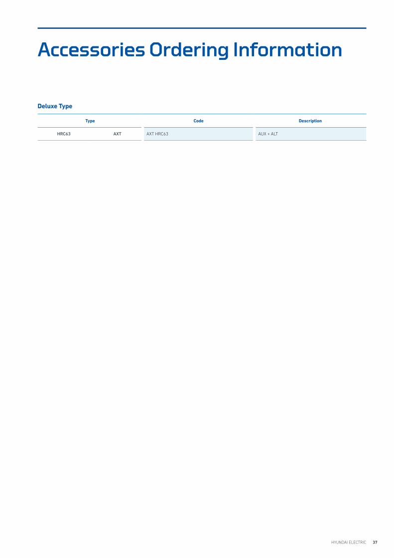
Accessories Ordering Information
Deluxe Type
Type Code Description
HRC63 AXT AXT HRC63 AUX + ALT
38 HG Modular Devices
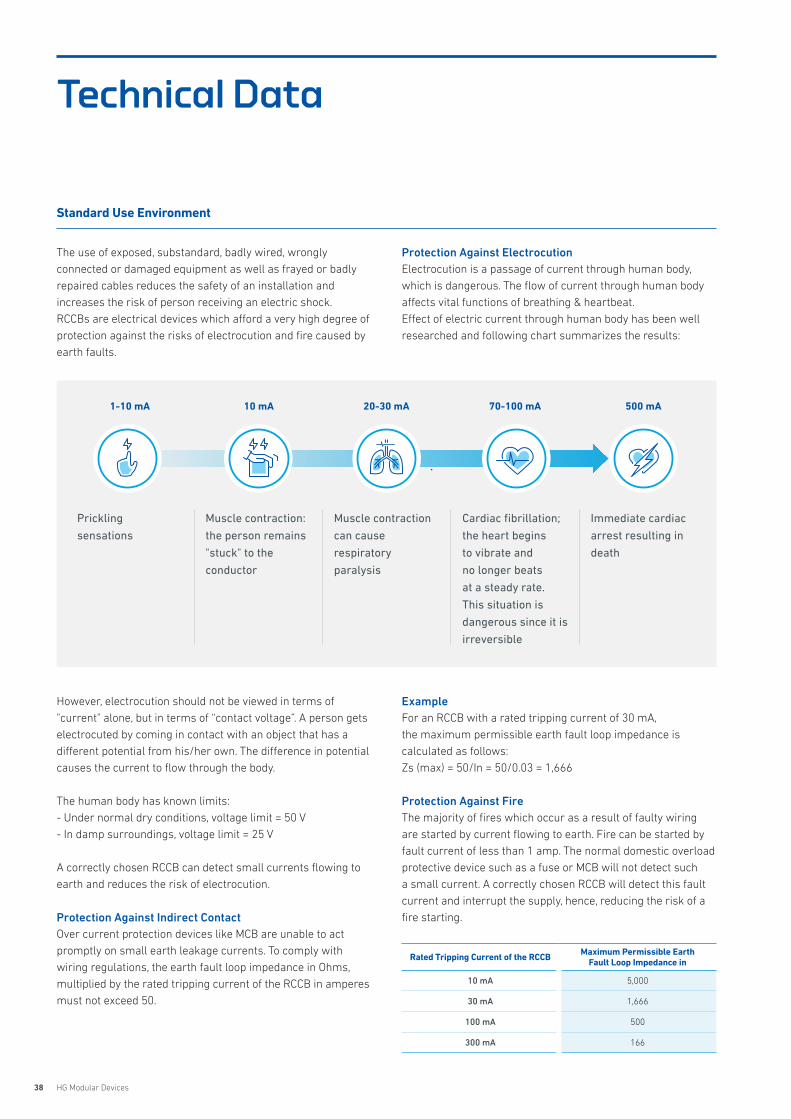
The use of exposed, substandard, badly wired, wrongly connected or damaged equipment as well as frayed or badly repaired cables reduces the safety of an installation and increases the risk of person receiving an electric shock. RCCBs are electrical devices which afford a very high degree of protection against the risks of electrocution and fire caused by earth faults.
However, electrocution should not be viewed in terms of "current" alone, but in terms of “contact voltage”. A person gets electrocuted by coming in contact with an object that has a different potential from his/her own. The difference in potential causes the current to flow through the body.
The human body has known limits: - Under normal dry conditions, voltage limit = 50 V- In damp surroundings, voltage limit = 25 V
A correctly chosen RCCB can detect small currents flowing to earth and reduces the risk of electrocution.
Protection Against Indirect ContactOver current protection devices like MCB are unable to act promptly on small earth leakage currents. To comply with wiring regulations, the earth fault loop impedance in Ohms, multiplied by the rated tripping current of the RCCB in amperes must not exceed 50.
Protection Against ElectrocutionElectrocution is a passage of current through human body, which is dangerous. The flow of current through human body affects vital functions of breathing & heartbeat.Effect of electric current through human body has been well researched and following chart summarizes the results:
ExampleFor an RCCB with a rated tripping current of 30 mA, the maximum permissible earth fault loop impedance is calculated as follows: Zs (max) = 50/In = 50/0.03 = 1,666
Protection Against FireThe majority of fires which occur as a result of faulty wiring are started by current flowing to earth. Fire can be started by fault current of less than 1 amp. The normal domestic overload protective device such as a fuse or MCB will not detect such a small current. A correctly chosen RCCB will detect this fault current and interrupt the supply, hence, reducing the risk of a fire starting.
Rated Tripping Current of the RCCB Maximum Permissible Earth Fault Loop Impedance in
10 mA 5,000
30 mA 1,666
100 mA 500
300 mA 166
Technical Data
Standard Use Environment
Immediate cardiac
arrest resulting in
death
Cardiac fibrillation;
the heart begins
to vibrate and
no longer beats
at a steady rate.
This situation is
dangerous since it is
irreversible
Muscle contraction
can cause
respiratory
paralysis
Muscle contraction:
the person remains
"stuck" to the
conductor
Prickling
sensations
500 mA70-100 mA20-30 mA10 mA1-10 mA
39HYUNDAI ELECTRIC
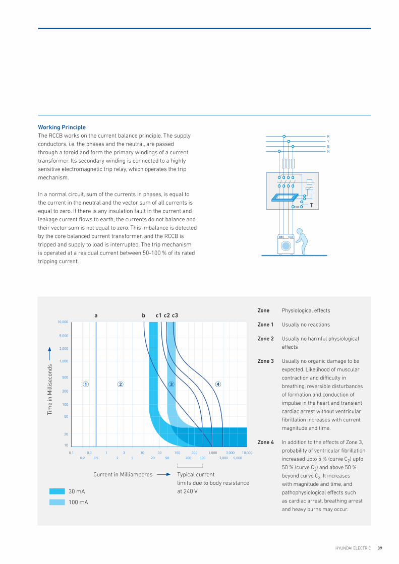
Working PrincipleThe RCCB works on the current balance principle. The supply conductors, i.e. the phases and the neutral, are passed through a toroid and form the primary windings of a current transformer. Its secondary winding is connected to a highly sensitive electromagnetic trip relay, which operates the trip mechanism.
In a normal circuit, sum of the currents in phases, is equal to the current in the neutral and the vector sum of all currents is equal to zero. If there is any insulation fault in the current and leakage current flows to earth, the currents do not balance and their vector sum is not equal to zero. This imbalance is detected by the core balanced current transformer, and the RCCB is tripped and supply to load is interrupted. The trip mechanism is operated at a residual current between 50-100 % of its rated tripping current.
Zone Physiological effects
Zone 1 Usually no reactions
Zone 2 Usually no harmful physiological
effects
Zone 3 Usually no organic damage to be
expected. Likelihood of muscular
contraction and difficulty in
breathing, reversible disturbances
of formation and conduction of
impulse in the heart and transient
cardiac arrest without ventricular
fibrillation increases with current
magnitude and time.
Zone 4 In addition to the effects of Zone 3,
probability of ventricular fibrillation
increased upto 5 % (curve C2) upto
50 % (curve C3) and above 50 %
beyond curve C3. It increases
with magnitude and time, and
pathophysiological effects such
as cardiac arrest, breathing arrest
and heavy burns may occur.
10,000
5,000
2,000
1,000
500
200
100
50
20
10
0.10.2 0.5 2 5 20 50 200 500 2,000 5,000
0.3 1 3 10 30 100 300 1,000 3,000 10,000
Tim
e in
Mill
isec
onds
Current in Milliamperes
30 mA
100 mA
Typical currentlimits due to body resistanceat 240 V
a b c1 c2 c3
RYBN
T
① ② ③ ④
40 HG Modular Devices
Technical Data
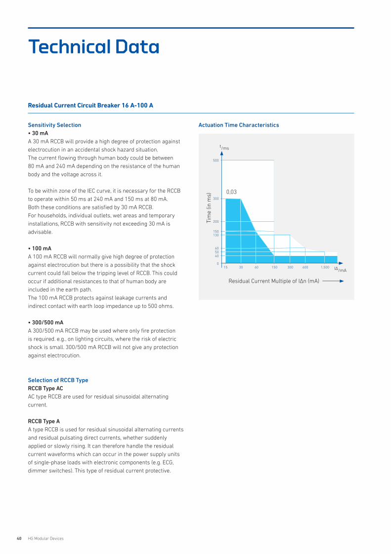
Sensitivity Selection• 30 mAA 30 mA RCCB will provide a high degree of protection against electrocution in an accidental shock hazard situation. The current flowing through human body could be between 80 mA and 240 mA depending on the resistance of the human body and the voltage across it.
To be within zone of the IEC curve, it is necessary for the RCCB to operate within 50 ms at 240 mA and 150 ms at 80 mA. Both these conditions are satisfied by 30 mA RCCB.For households, individual outlets, wet areas and temporary installations, RCCB with sensitivity not exceeding 30 mA is advisable.
• 100 mAA 100 mA RCCB will normally give high degree of protection against electrocution but there is a possibility that the shock current could fall below the tripping level of RCCB. This could occur if additional resistances to that of human body are included in the earth path. The 100 mA RCCB protects against leakage currents and indirect contact with earth loop impedance up to 500 ohms.
• 300/500 mAA 300/500 mA RCCB may be used where only fire protection is required. e.g., on lighting circuits, where the risk of electric shock is small. 300/500 mA RCCB will not give any protection against electrocution.
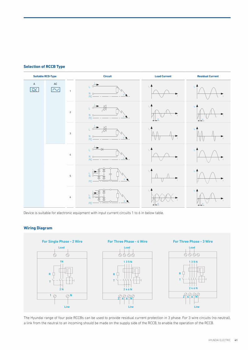
Selection of RCCB TypeRCCB Type ACAC type RCCB are used for residual sinusoidal alternating current.
RCCB Type AA type RCCB is used for residual sinusoidal alternating currents and residual pulsating direct currents, whether suddenly applied or slowly rising. It can therefore handle the residual current waveforms which can occur in the power supply units of single-phase loads with electronic components (e.g. ECG, dimmer switches). This type of residual current protective.
Actuation Time Characteristics
Residual Current Circuit Breaker 16 A-100 A
Tim
e (in
ms)
Residual Current Multiple of IΔn (mA)
0,03
500
300
200
150130
1,50060030015 30 60 150
605040
0
t/ms
IΔ/mA
41HYUNDAI ELECTRIC
Suitable RCD-Type Circuit Load Current Residual Current
A AC
1
2
3
4
5
6
Selection of RCCB Type
Wiring Diagram
iL
iF
L
NPE
iL
iF
L
NPE
iL
iF
L
NPE
iL
iF
L
NPE
iL
iF
LN
PE
iL
iF
LN
PE
iL
t
t
t
t
t
t
iL
α
α
iL
iL
iL
iL
iF
t
t
t
t
t
t
iF
α
α
iF
iF
iF
iF
The Hyundai range of four pole RCCBs can be used to provide residual current protection in 3 phase. For 3 wire circuits (no neutral), a link from the neutral to an incoming should be made on the supply side of the RCCB, to enable the operation of the RCCB.
For Single Phase - 2 Wire
1N
Load
2 N
1
Line
N
For Three Phase - 4 Wire
Load
1 3 5 N
2 4 6 N
Line
R
T
For Three Phase - 3 Wire
Load
1 3 5 N
2 4 6 N
Line
R
T
R
T
2 4 6 N 2 4 6 N
Device is suitable for electronic equipment with input current circuits 1 to 6 in below table.
42 HG Modular Devices
Technical Data
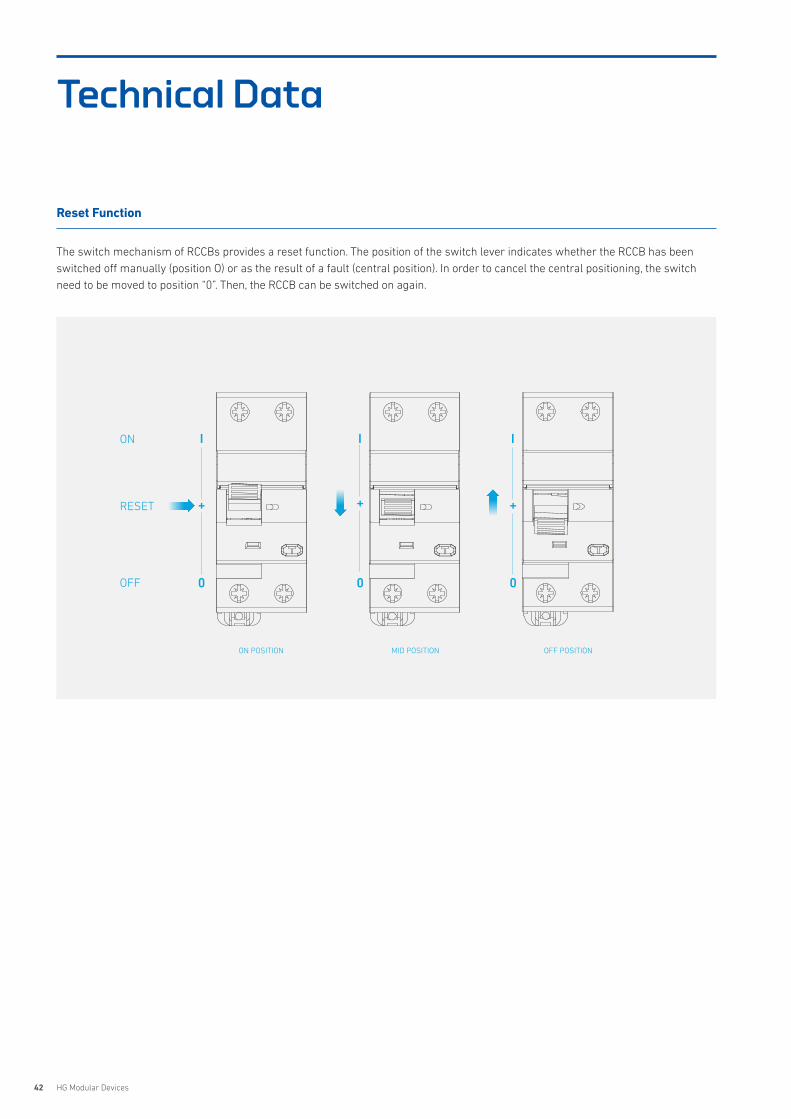
Reset Function
The switch mechanism of RCCBs provides a reset function. The position of the switch lever indicates whether the RCCB has been switched off manually (position O) or as the result of a fault (central position). In order to cancel the central positioning, the switch need to be moved to position “0”. Then, the RCCB can be switched on again.
ON POSITION MID POSITION OFF POSITION
ON I
0
+
I
0
+
I
0
+RESET
OFF
43HYUNDAI ELECTRIC
72.0
87.5
5.3
87.5
45.0
92.8
87.5
42
35.9 50.8
6.8
44
62
71.7
72.0 35.9 71.7
6.8
44.062.0
88.2
88.2
36.0
45.0
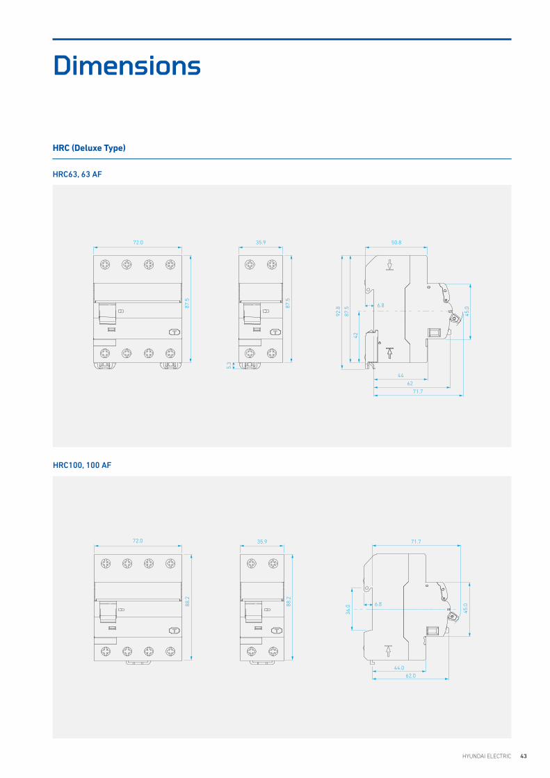
HRC100, 100 AF
HRC (Deluxe Type)
HRC63, 63 AF
Dimensions
44 HG Modular Devices
HRC100S, 100 AF
HRC (Standard Type)
HRC63S, 63 AF
81.0
35.8 71.6
45.0
51.0
85.0
66.8
79.5
74.0
36.0
81.0
90.9
35.8 71.6
90.9
95.0
51.2
67.0
36.0
45.0
74.0
79.5
Dimensions
45HYUNDAI ELECTRIC
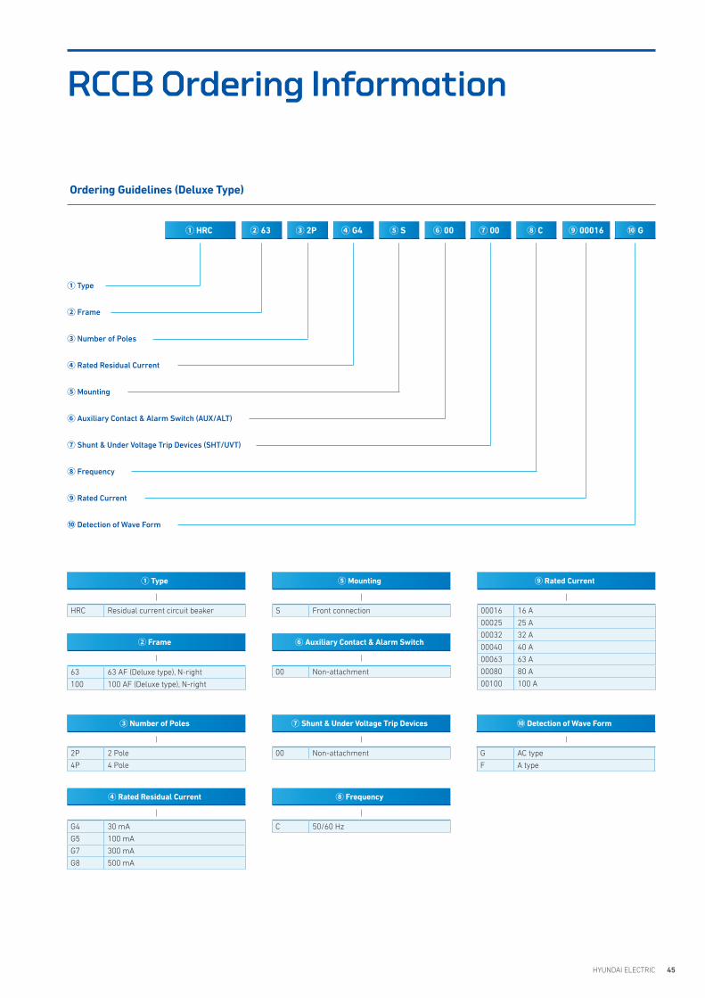
RCCB Ordering Information
② Frame
63 63 AF (Deluxe type), N-right
100 100 AF (Deluxe type), N-right
00016 16 A
00025 25 A
00032 32 A
00040 40 A
00063 63 A
00080 80 A
00100 100 A
⑨ Rated Current
G AC type
F A type
⑩ Detection of Wave Form
00 Non-attachment
⑥ Auxiliary Contact & Alarm Switch
C 50/60 Hz
⑧ Frequency
00 Non-attachment
⑦ Shunt & Under Voltage Trip Devices
① Type
HRC Residual current circuit beaker
③ Number of Poles
2P 2 Pole
4P 4 Pole
④ Rated Residual Current
G4 30 mA
G5 100 mA
G7 300 mA
G8 500 mA
S Front connection
⑤ Mounting
Ordering Guidelines (Deluxe Type)
① Type
② Frame
③ Number of Poles
④ Rated Residual Current
⑤ Mounting
⑥ Auxiliary Contact & Alarm Switch (AUX/ALT)
⑦ Shunt & Under Voltage Trip Devices (SHT/UVT)
⑧ Frequency
⑨ Rated Current
⑩ Detection of Wave Form
① HRC ② 63 ③ 2P ④ G4 ⑥ 00⑤ S ⑦ 00 ⑧ C ⑨ 00016 ⑩ G
46 HG Modular Devices
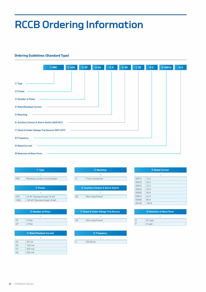
RCCB Ordering Information
② Frame
63S 63 AF (Standard type), N-left
100S 100 AF (Standard type), N-left
00016 16 A
00025 25 A
00032 32 A
00040 40 A00050 50 A
00063 63 A
00080 80 A
00100 100 A
⑨ Rated Current
G AC type
F A type
⑩ Detection of Wave Form
00 Non-attachment
⑥ Auxiliary Contact & Alarm Switch
C 50/60 Hz
⑧ Frequency
00 Non-attachment
⑦ Shunt & Under Voltage Trip Devices
① Type
HRC Residual current circuit beaker
③ Number of Poles
2P 2 Pole
4P 4 Pole
④ Rated Residual Current
G4 30 mA
G5 100 mA
G7 300 mA
G8 500 mA
S Front connection
⑤ Mounting
① HRC ② 63S ③ 2P ④ G4 ⑥ 00⑤ S ⑦ 00 ⑧ C ⑨ 00016 ⑩ G
Ordering Guidelines (Standard Type)
① Type
② Frame
③ Number of Poles
④ Rated Residual Current
⑤ Mounting
⑥ Auxiliary Contact & Alarm Switch (AUX/ALT)
⑦ Shunt & Under Voltage Trip Devices (SHT/UVT)
⑧ Frequency
⑨ Rated Current
⑩ Detection of Wave Form
47HYUNDAI ELECTRIC
Features 48
Selection Table 50
Dimensions 52
Order Information 54
HSDMiniature Switch Disconnector
48 HG Modular Devices
Features
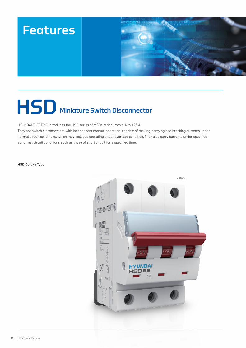
HSD Miniature Switch Disconnector
HSD63
HSD Deluxe Type
HYUNDAI ELECTRIC introduces the HSD series of MSDs rating from 6 A to 125 A.
They are switch disconnectors with independent manual operation, capable of making, carrying and breaking currents under
normal circuit conditions, which may includes operating under overload condition. They also carry currents under specified
abnormal circuit conditions such as those of short circuit for a specified time.
49HYUNDAI ELECTRIC
Hyundai HSD type switch disconnectors are mainly used for isolation and switching in the terminal
combined electric appliances under the alternating current 50/60 Hz, rated voltage AC 240 V or
AC 415 V and with rated current 6 to 125 A.
The double point direct moving structure enlarges the current capacity while making full use of the
electrical power supplement. In addition, power reserving handle mechanism with high on/off speed
promotes the working reliability. HSD type breakers comply with IEC/EN standard, and can be applied
to industry, commerce, high-rise buildings, household and other similar installations.
Product Features
Product Overview
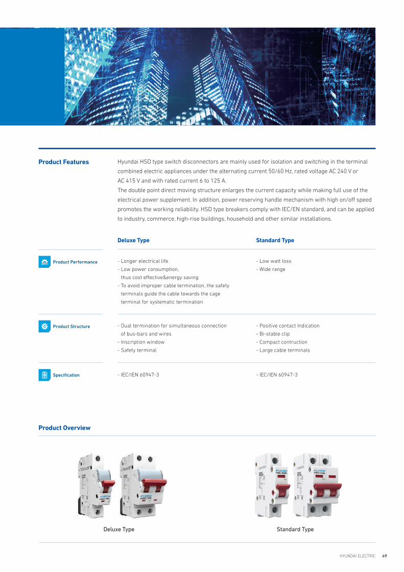
Deluxe Type Standard Type
Deluxe Type Standard Type
Product Performance - Longer electrical life
- Low power consumption,
thus cost effective&energy saving
- To avoid improper cable termination, the safety
terminals guide the cable towards the cage
terminal for systematic termination
- Low watt loss
- Wide range
Product Structure - Dual termination for simultaneous connection
of bus-bars and wires
- Inscription window
- Safety terminal
- Positive contact Indication
- Bi-stable clip
- Compact contruction
- Large cable terminals
Specification - IEC/IEN 60947-3 - IEC/IEN 60947-3
50 HG Modular Devices
Selection Table
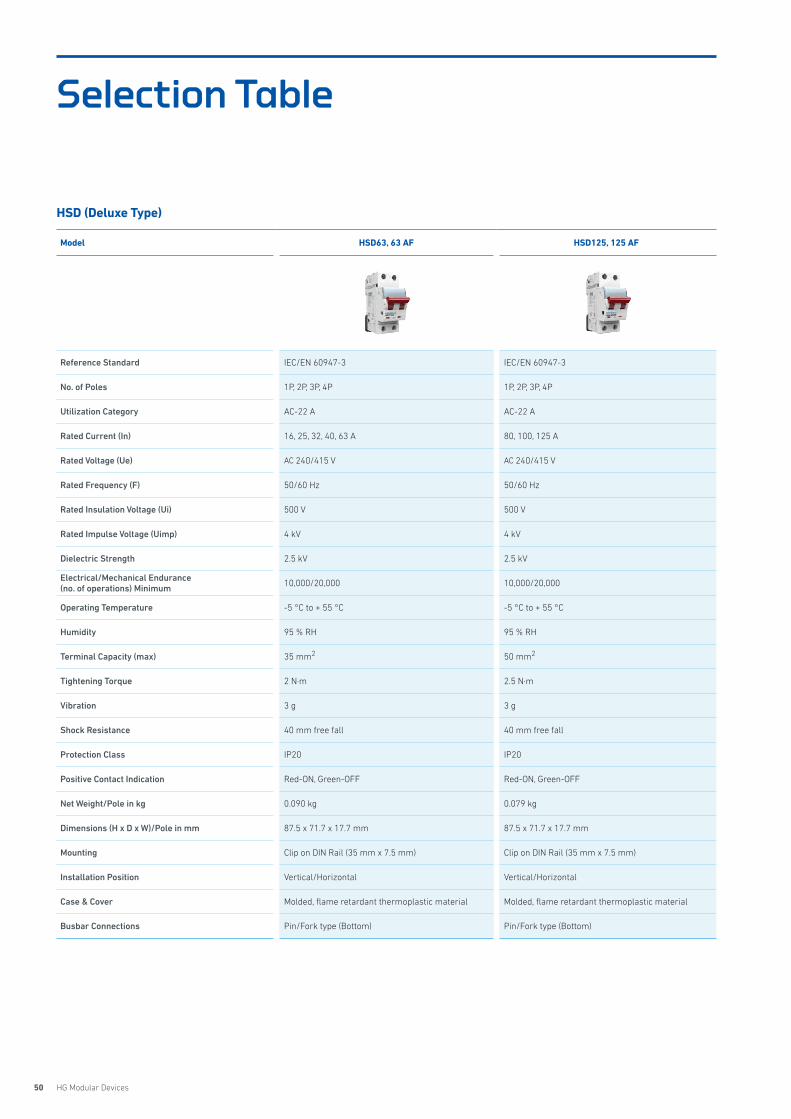
Model HSD63, 63 AF HSD125, 125 AF
Reference Standard IEC/EN 60947-3 IEC/EN 60947-3
No. of Poles 1P, 2P, 3P, 4P 1P, 2P, 3P, 4P
Utilization Category AC-22 A AC-22 A
Rated Current (In) 16, 25, 32, 40, 63 A 80, 100, 125 A
Rated Voltage (Ue) AC 240/415 V AC 240/415 V
Rated Frequency (F) 50/60 Hz 50/60 Hz
Rated Insulation Voltage (Ui) 500 V 500 V
Rated Impulse Voltage (Uimp) 4 kV 4 kV
Dielectric Strength 2.5 kV 2.5 kV
Electrical/Mechanical Endurance(no. of operations) Minimum 10,000/20,000 10,000/20,000
Operating Temperature -5 °C to + 55 °C -5 °C to + 55 °C
Humidity 95 % RH 95 % RH
Terminal Capacity (max) 35 mm2 50 mm2
Tightening Torque 2 N·m 2.5 N·m
Vibration 3 g 3 g
Shock Resistance 40 mm free fall 40 mm free fall
Protection Class IP20 IP20
Positive Contact Indication Red-ON, Green-OFF Red-ON, Green-OFF
Net Weight/Pole in kg 0.090 kg 0.079 kg
Dimensions (H x D x W)/Pole in mm 87.5 x 71.7 x 17.7 mm 87.5 x 71.7 x 17.7 mm
Mounting Clip on DIN Rail (35 mm x 7.5 mm) Clip on DIN Rail (35 mm x 7.5 mm)
Installation Position Vertical/Horizontal Vertical/Horizontal
Case & Cover Molded, flame retardant thermoplastic material Molded, flame retardant thermoplastic material
Busbar Connections Pin/Fork type (Bottom) Pin/Fork type (Bottom)
HSD (Deluxe Type)
51HYUNDAI ELECTRIC
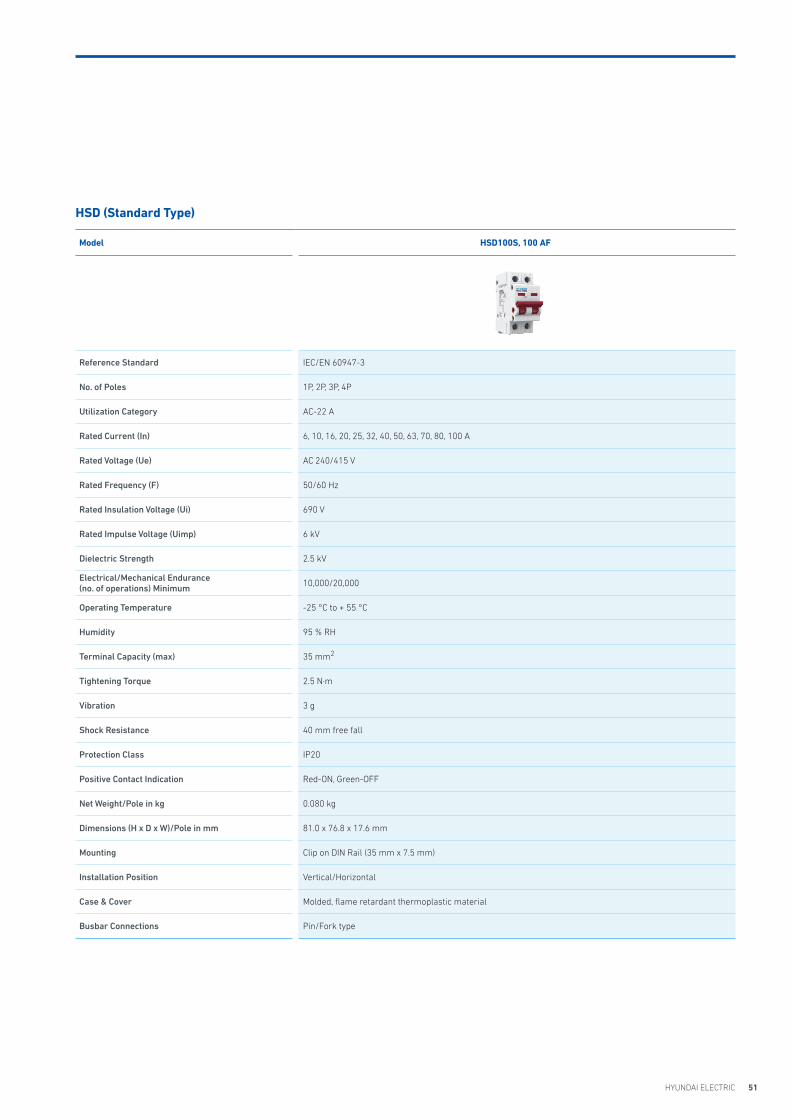
Model HSD100S, 100 AF
Reference Standard IEC/EN 60947-3
No. of Poles 1P, 2P, 3P, 4P
Utilization Category AC-22 A
Rated Current (In) 6, 10, 16, 20, 25, 32, 40, 50, 63, 70, 80, 100 A
Rated Voltage (Ue) AC 240/415 V
Rated Frequency (F) 50/60 Hz
Rated Insulation Voltage (Ui) 690 V
Rated Impulse Voltage (Uimp) 6 kV
Dielectric Strength 2.5 kV
Electrical/Mechanical Endurance(no. of operations) Minimum 10,000/20,000
Operating Temperature -25 °C to + 55 °C
Humidity 95 % RH
Terminal Capacity (max) 35 mm2
Tightening Torque 2.5 N·m
Vibration 3 g
Shock Resistance 40 mm free fall
Protection Class IP20
Positive Contact Indication Red-ON, Green-OFF
Net Weight/Pole in kg 0.080 kg
Dimensions (H x D x W)/Pole in mm 81.0 x 76.8 x 17.6 mm
Mounting Clip on DIN Rail (35 mm x 7.5 mm)
Installation Position Vertical/Horizontal
Case & Cover Molded, flame retardant thermoplastic material
Busbar Connections Pin/Fork type
HSD (Standard Type)

52 HG Modular Devices
Dimensions
HSD125, 125 AF
HSD63, 63 AF
50.8
6.8
4462
71.7
70.817.7
87.5
5.3
87.5
5.3
87.5
5.3
87.5
92.8
87.5
42
45.0
5.3
35.4 53.1
50.870.853.135.417.7
4462
73.4
6.8
92.8
87.5
87.5
87.5
87.5
5.3
5.3
5.3
5.3
87.5
45.0
42
HSD (Deluxe Type)
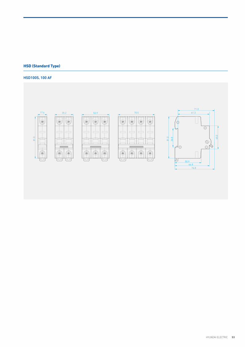
53HYUNDAI ELECTRIC
HSD (Standard Type)
HSD100S, 100 AF
17.6 35.2 52.9 70.5 61.3
71.0
50.9
45.0
81.0
81.0
36.0
66.876.8
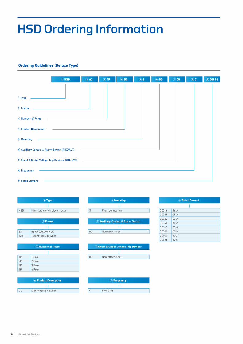
54 HG Modular Devices
HSD Ordering Information
② Frame
63 63 AF (Deluxe type)
125 125 AF (Deluxe type)
00016 16 A
00025 25 A
00032 32 A
00040 40 A
00063 63 A
00080 80 A
00100 100 A
00125 125 A
⑨ Rated Current
00 Non-attachment
⑥ Auxiliary Contact & Alarm Switch
C 50/60 Hz
⑧ Frequency
00 Non-attachment
⑦ Shunt & Under Voltage Trip Devices
① Type
HSD Miniature switch disconnector
③ Number of Poles
1P 1 Pole
2P 2 Pole
3P 3 Pole
4P 4 Pole
④ Product Description
DS Disconnection switch
S Front connection
⑤ Mounting
① HSD ② 63 ③ 1P ④ DS ⑥ 00⑤ S ⑦ 00 ⑧ C ⑨ 00016
Ordering Guidelines (Deluxe Type)
① Type
② Frame
③ Number of Poles
④ Product Description
⑤ Mounting
⑥ Auxiliary Contact & Alarm Switch (AUX/ALT)
⑦ Shunt & Under Voltage Trip Devices (SHT/UVT)
⑧ Frequency
⑨ Rated Current

55HYUNDAI ELECTRIC
② Frame
100S 100 AF (Standard type)
00016 16 A
00025 25 A
00032 32 A
00040 40 A
00063 63 A
00080 80 A
00100 100 A
⑨ Rated Current
00 Non-attachment
⑥ Auxiliary Contact & Alarm Switch
C 50/60 Hz
⑧ Frequency
00 Non-attachment
⑦ Shunt & Under Voltage Trip Devices
① Type
HSD Miniature switch disconnector
③ Number of Poles
1P 1 Pole
2P 2 Pole
3P 3 Pole
4P 4 Pole
④ Product Description
DS Disconnection switch
S Front connection
⑤ Mounting
① HSD ② 100S ③ 1P ④ DS ⑥ 00⑤ S ⑦ 00 ⑧ C ⑨ 00016
Ordering Guidelines (Standard Type)
① Type
② Frame
③ Number of Poles
④ Product Description
⑤ Mounting
⑥ Auxiliary Contact & Alarm Switch (AUX/ALT)
⑦ Shunt & Under Voltage Trip Devices (SHT/UVT)
⑧ Frequency
⑨ Rated Current

57HYUNDAI ELECTRIC
Features 58
Selection Table 60
Operation 61
Technical Data 62
Dimensions 63
Ordering Information 64
HECElectronic Circuit Breaker
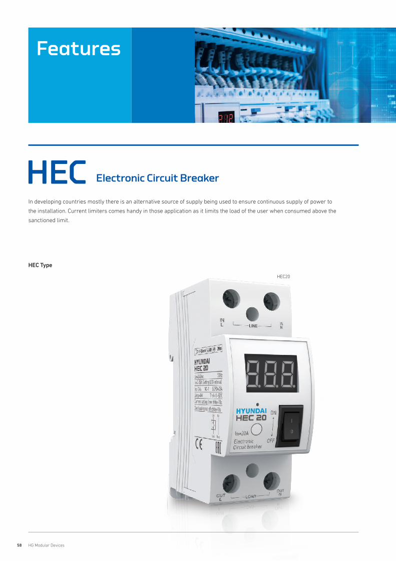
58 HG Modular Devices
Features
HEC Electronic Circuit Breaker
In developing countries mostly there is an alternative source of supply being used to ensure continuous supply of power to
the installation. Current limiters comes handy in those application as it limits the load of the user when consumed above the
sanctioned limit.
HEC20
HEC Type
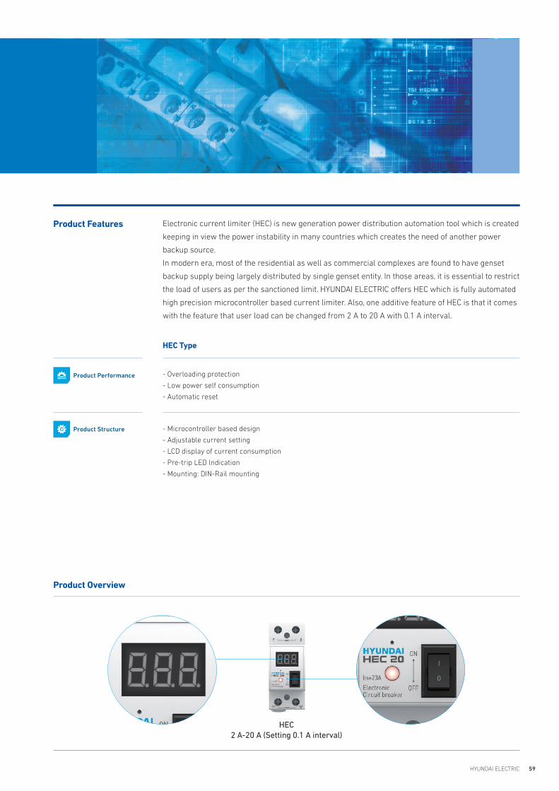
59HYUNDAI ELECTRIC
Electronic current limiter (HEC) is new generation power distribution automation tool which is created
keeping in view the power instability in many countries which creates the need of another power
backup source.
In modern era, most of the residential as well as commercial complexes are found to have genset
backup supply being largely distributed by single genset entity. In those areas, it is essential to restrict
the load of users as per the sanctioned limit. HYUNDAI ELECTRIC offers HEC which is fully automated
high precision microcontroller based current limiter. Also, one additive feature of HEC is that it comes
with the feature that user load can be changed from 2 A to 20 A with 0.1 A interval.
Product Features
Product Overview
HEC Type
- Overloading protection
- Low power self consumption
- Automatic reset
- Microcontroller based design
- Adjustable current setting
- LCD display of current consumption
- Pre-trip LED lndication
- Mounting: DIN-Rail mounting
Product Performance
Product Structure
HEC 2 A-20 A (Setting 0.1 A interval)
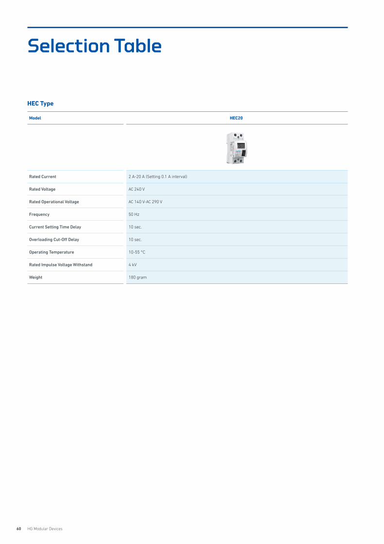
60 HG Modular Devices
Model HEC20
Rated Current 2 A-20 A (Setting 0.1 A interval)
Rated Voltage AC 240 V
Rated Operational Voltage AC 140 V-AC 290 V
Frequency 50 Hz
Current Setting Time Delay 10 sec.
Overloading Cut-Off Delay 10 sec.
Operating Temperature 10-55 °C
Rated Impulse Voltage Withstand 4 kV
Weight 180 gram
HEC Type
Selection Table
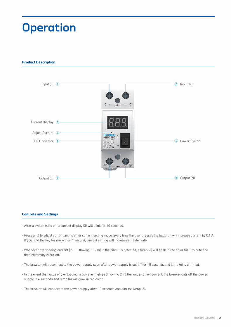
61HYUNDAI ELECTRIC
Operation
- After a switch (4) is on, a current display (3) will blink for 10 seconds.
- Press a (5) to adjust current and to enter current setting mode. Every time the user presses the button, it will increase current by 0.1 A. If you hold the key for more than 1 second, current setting will increase at faster rate.
- Whenever overloading current [In I flowing 2 In] in the circuit is detected, a lamp (6) will flash in red color for 1 minute and then electrciity is cut-off.
- The breaker will reconnect to the power supply soon after power supply is cut off for 10 seconds and lamp (6) is dimmed.
- In the event that value of overloading is twice as high as [I flowing 2 In] the values of set current, the breaker cuts off the power supply in 4 seconds and lamp (6) will glow in red color.
- The breaker will connect to the power supply after 10 seconds and dim the lamp (6).
Product Description
Controls and Settings
Input (L) Input (N)
Current Display
Adjust Current
LED Indicator Power Switch
Output (N)Output (L)
2
3
4
5
6
7 8
1
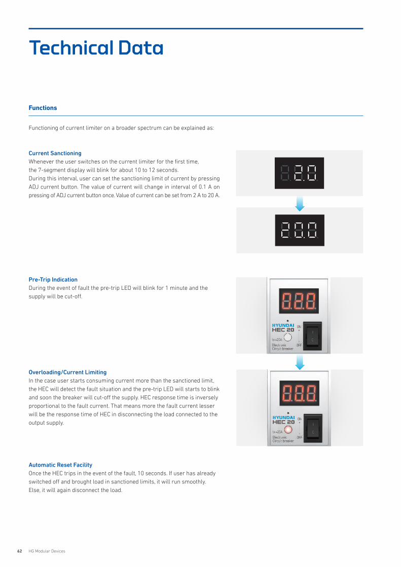
62 HG Modular Devices
Functioning of current limiter on a broader spectrum can be explained as:
Current SanctioningWhenever the user switches on the current limiter for the first time, the 7-segment display will blink for about 10 to 12 seconds.During this interval, user can set the sanctioning limit of current by pressing ADJ current button. The value of current will change in interval of 0.1 A on pressing of ADJ current button once. Value of current can be set from 2 A to 20 A.
Pre-Trip IndicationDuring the event of fault the pre-trip LED will blink for 1 minute and the supply will be cut-off.
Overloading/Current LimitingIn the case user starts consuming current more than the sanctioned limit, the HEC will detect the fault situation and the pre-trip LED will starts to blink and soon the breaker will cut-off the supply. HEC response time is inversely proportional to the fault current. That means more the fault current lesser will be the response time of HEC in disconnecting the load connected to the output supply.
Automatic Reset FacilityOnce the HEC trips in the event of the fault, 10 seconds. If user has already switched off and brought load in sanctioned limits, it will run smoothly. Else, it will again disconnect the load.
Technical Data
Functions

63HYUNDAI ELECTRIC
Dimensions
HEC
HEC20
35.9
4587.5
42
62
44
5.2
6.8

64 HG Modular Devices
HEC Ordering Information
① Type
HEC Electronic circuit breaker
② Frame
20 HEC20
③ Number of Poles
2P 2 Pole
④ Rated Current
00020 2 A-20 A
① HEC ② 20
Ordering Guidelines
① Type
② Frame
③ Number of Poles
④ Rated Current
③ 2P ④ 00020
65HYUNDAI ELECTRIC
Features 66
Selection Table 69
Dimensions/Circuit Diagram 70
Order Information 72
HICInstallation Contactor
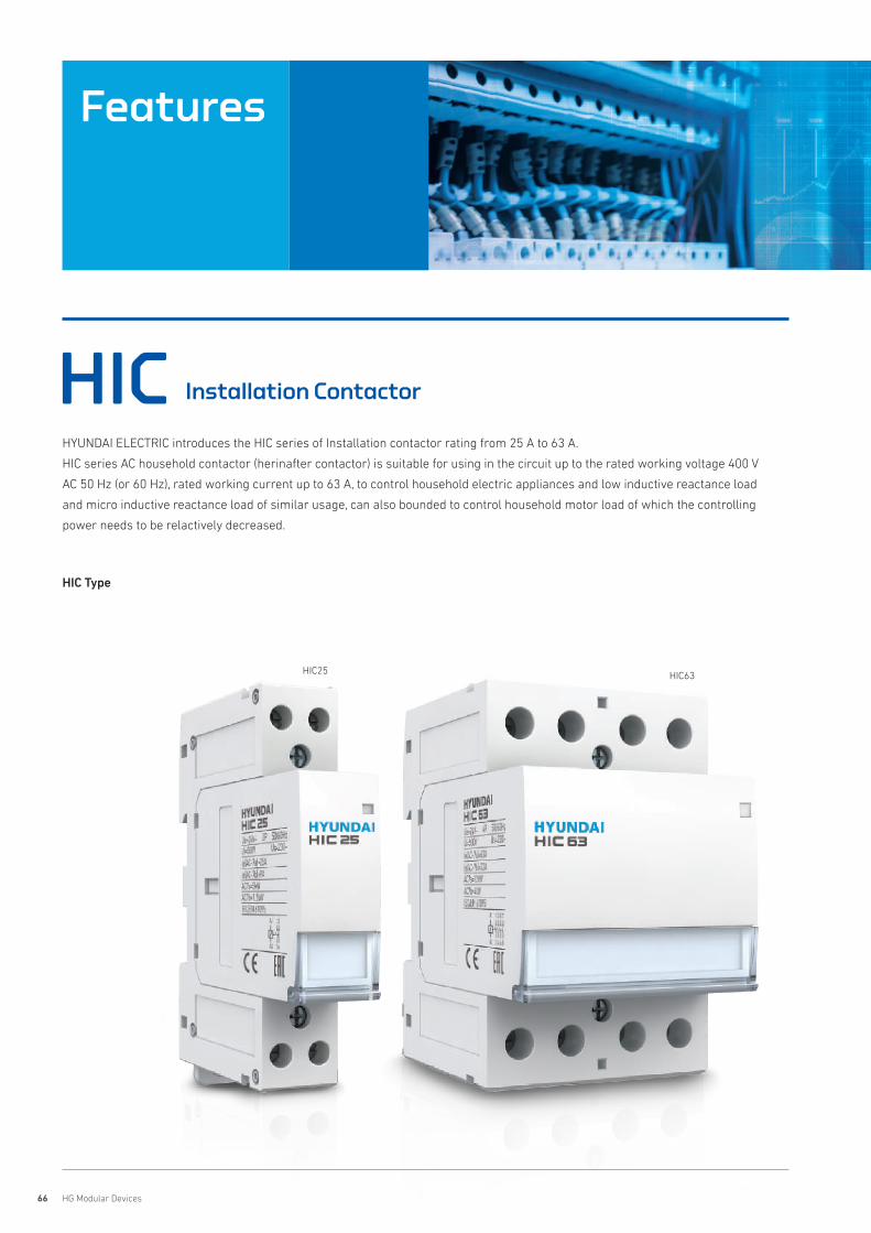
66 HG Modular Devices
HIC Installation Contactor
HYUNDAI ELECTRIC introduces the HIC series of Installation contactor rating from 25 A to 63 A.
HIC series AC household contactor (herinafter contactor) is suitable for using in the circuit up to the rated working voltage 400 V
AC 50 Hz (or 60 Hz), rated working current up to 63 A, to control household electric appliances and low inductive reactance load
and micro inductive reactance load of similar usage, can also bounded to control household motor load of which the controlling
power needs to be relactively decreased.
HIC63HIC25
HIC Type
Features
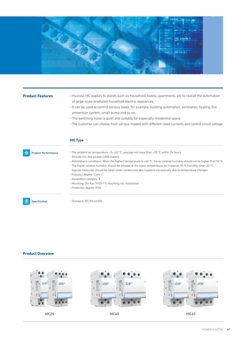
67HYUNDAI ELECTRIC
- Hyundai HIC applies to places such as household, hotels, apartments, etc to realize the automation
of large-scale produced household electric appliances.
- It can be used to control various loads, for example, building automation, ventilation, heating, fire
prevention system, small pump and so on.
- The switching noise is quiet and suitable for especially residential space.
- The customer can choose from various models with different rated currents and control circuit voltage.
Product Features
Product Overview
HIC25 HIC40 HIC63
HIC Type
- The ambient air temperature: -5~+40 °C, average not more than +35 °C within 24 hours
- Altitude (m): Not exceed 2,000 meters
- Atmospheric conditions: When the highest temperature is +40 °C, the air relative humidity should not be higher than 50 %.
The higher relative humidity should be allowed at the lower temperature, for instance, 90 % humidity when 20 °C.
Special measures should be taken when condensate dew happens occasionally due to temperature changes.
- Pollution degree: Class 2
- Installation category:Ⅱ
- Mounting: Din Rail TH35-7.5 mounting rail installation
- Protection degree: IP20
- Standard: IEC/EN 61095
Product Performance
Specification
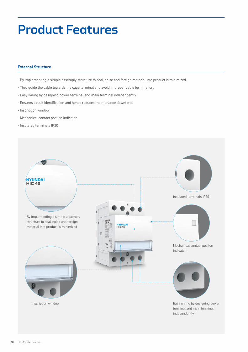
68 HG Modular Devices
Product Features
External Structure
- By implementing a simple assemply structure to seal, noise and foreign meterial into product is minimized.
- They guide the cable towards the cage terminal and avoid improper cable termination.
- Easy wiring by designing power terminal and main terminal independently.
- Ensures circuit identification and hence reduces maintenance downtime.
- Inscription window
- Mechanical contact postion indicator
- Insulated terminals IP20
By implementing a simple assembly
structure to seal, noise and foreign
meterial into product is minimized
Inscription window Easy wiring by designing power
terminal and main terminal
independently
Mechanical contact positon
indicator
Insulated terminals IP20

69HYUNDAI ELECTRIC
HIC Type
Selection Table
Model HIC25 HIC40 HIC63
Reference Standard IEC/EN 61095 IEC/EN 61095 IEC/EN 61095
No. of Poles 2P, 4P 2P, 4P 2P, 4P
Rated Current (In) 25 A 40 A 63 A
Rated Voltage (Ue) 2P: 230 V 4P: 400 V 2P: 230 V 4P: 400 V 2P: 230 V 4P: 400 V
Rated Voltage (Ui) 500 V 500 V 500 V
Rated Control Voltage (Uc) 24 V, 48 V, 230 V 24 V, 48 V, 230 V 24 V, 48 V, 230 V
Rated Frequency (F) 50/60 Hz 50/60 Hz 50/60 Hz
Using CategoryAC-1AC-7aAC-7b
AC-1AC-7aAC-7b
AC-1AC-7aAC-7b
Electrical Endurance 100,000 cycles 100,000 cycles 100,000 cycles
Mechanical Endurance 1,000,000 cycles 1,000,000 cycles 1,000,000 cycles
Rated Power
2P- 5 kW (AC-7a)- 1.2 kW (AC-7b)
4P4NO/3NO + 1NC/4NC: - 14 kW (AC-7a)- 4 kW (AC-7b)2NO + 2NC - 5 kW (AC-7a)- 1.2 kW (AC-7b)
2P- 7.6 kW (AC-7a)- 2.5 kW (AC-7b)
4P4NO/3NO + 1NC/4NC: - 26.5 kW (AC-7a)- 6.5 kW (AC-7b)2NO + 2NC - 7.6 kW (AC-7a)- 2.5 kW (AC-7b)
2P- 12 kW (AC-7a)- 4 kW (AC-7b)
4P4NO/3NO + 1NC/4NC: - 40 kW (AC-7a)- 14 kW (AC-7b)2NO + 2NC - 12 kW (AC-7a)- 4 kW (AC-7b)
Rated Operation Current (Ie)25 A (AC-1/AC-7a)9 A (AC-7b)
40 A (AC-1/AC-7a)15 A (AC-7b)
63 A (AC-1/AC-7a)32 A (AC-7b)
Operating Temperature -5 °C to + 55 °C -5 °C to + 55 °C -5 °C to + 55 °C
Humidity 90 % (@ 20 °C)50 % (@ 40 °C)
90 % (@ 20 °C)50 % (@ 40 °C)
90 % (@ 20 °C)50 % (@ 40 °C)
Terminal Capacity (max) 6 mm² 25 mm² 25 mm²
Tightening Torque 1.2 N·m 2.5 N·m 2.5 N·m
Protection Class IP20 IP20 IP20
Net Weight/Pole in kg 2P: 134.8 g; 4P: 235.6 g 2P: 242.6 g; 4P: 340.4 g 2P: 242.6 g; 4P: 340.4 g
Dimensions (H x D x W)/Pole in mm2P 18 x 85 x 62.5 mm4P 36 x 85 x 62.5 mm
2P 36 x 85 x 62.5 mm4P 54 x 85 x 62.5 mm
2P 36 x 85 x 62.5 mm4P 54 x 85 x 62.5 mm
Mounting Clip on DIN Rail (35 mm x 7.5 mm) Clip on DIN Rail (35 mm x 7.5 mm) Clip on DIN Rail (35 mm x 7.5 mm)
Busbar Connection Top/Bottom Side
Pin type Pin type Pin type

70 HG Modular Devices
Dimensions
HIC
HIC40, 40 AF
HIC63, 63 AF
HIC25, 25 AF
358590.5
45
44.5
62.55.5
358590.5
45
44.5
62.55.5
36 54
358590.5
45
44.5
62.55.5
358590.5
45
44.5
62.55.5
36
18 36
54
358590.5
45
44.5
62.55.5358590
.5
45
44.5
62.55.5
36 54
358590.5
45
44.5
62.55.5
358590.5
45
44.5
62.55.5
36
18 36
54
358590.5
45
44.5
62.55.5
358590.5
45
44.5
62.55.5
36 54
358590.5
45
44.5
62.55.5
358590.5
45
44.5
62.55.5
36
18 36
54
2P
2P
2P
4P
4P
4P
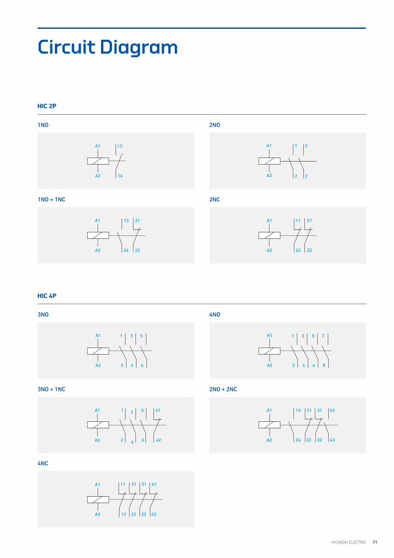
71HYUNDAI ELECTRIC
Circuit Diagram
HIC 2P
HIC 4P
2NO1NO
3NO
3NO + 1NC
4NC
1NO + 1NC 2NC
4NO
2NO + 2NC
A1 1
2
2
2A2
A1 13
24
21
22A2
A1 13
14A2
A1 1
2
3
4
5
6
7
8A2
A1 1
2
3
4
5
6A2
11
12
21
22
31
32
41
42
A1
A2
1
2
5
6
41
42
A1
A2
13
24
21
22
31
32
43
43
A1
A2
A1 11 21
22 22A2
4
2
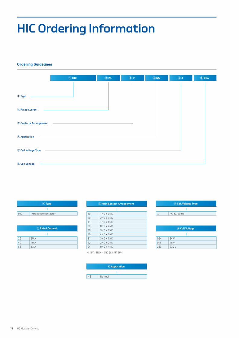
72 HG Modular Devices
HIC Ordering Information
① Type
HIC Installation contactor
② Rated Current
25 25 A
40 40 A
63 63 A
③ Main Contact Arrangement
10 1NO + 0NC
20 2NO + 0NC
11 1NO + 1NC
02 0NO + 2NC
30 3NO + 0NC
40 4NO + 0NC
31 3NO + 1NC
22 2NO + 2NC
04 0NO + 4NC
X AC 50/60 Hz
⑤ Coil Voltage Type
⑥ Coil Voltage
024 24 V
048 48 V
230 230 V
NS Normal
④ Application
① HIC ② 25 ③ 11 ④ NS ⑥ 024⑤ X
Ordering Guidelines
① Type
② Rated Current
③ Contacts Arrangement
④ Application
⑤ Coil Voltage Type
⑥ Coil Voltage
※ N/A: 1NO + 0NC (63 AF, 2P)
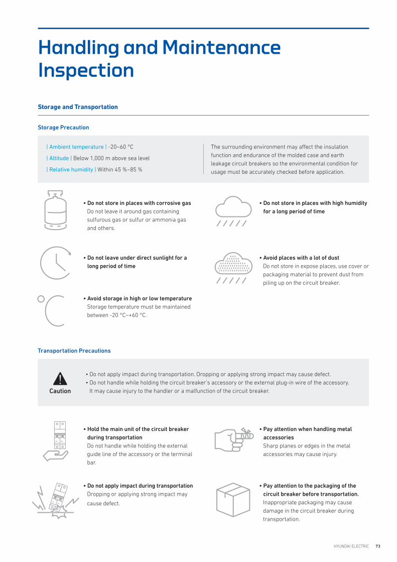
73HYUNDAI ELECTRIC
• Avoid places with a lot of dust Do not store in expose places, use cover or packaging material to prevent dust from piling up on the circuit breaker.
• Do not store in places with high humidity for a long period of time
Storage and Transportation
Handling and Maintenance Inspection
Storage Precaution
Transportation Precautions
| Ambient temperature | -20~60 °C
| Altitude | Below 1,000 m above sea level
| Relative humidity | Within 45 %~85 %
The surrounding environment may affect the insulation function and endurance of the molded case and earth leakage circuit breakers so the environmental condition for usage must be accurately checked before application.
• Do not store in places with corrosive gasDo not leave it around gas containing sulfurous gas or sulfur or ammonia gas and others.
• Hold the main unit of the circuit breaker during transportationDo not handle while holding the external guide line of the accessory or the terminal bar.
• Pay attention when handling metal accessoriesSharp planes or edges in the metal accessories may cause injury.
• Do not apply impact during transportationDropping or applying strong impact may
cause defect.
• Pay attention to the packaging of the circuit breaker before transportation.Inappropriate packaging may cause damage in the circuit breaker during transportation.
• Avoid storage in high or low temperature Storage temperature must be maintained between -20 °C~+60 °C.
• Do not leave under direct sunlight for a long period of time
• Do not apply impact during transportation. Dropping or applying strong impact may cause defect. • Do not handle while holding the circuit breaker’s accessory or the external plug-in wire of the accessory.
It may cause injury to the handler or a malfunction of the circuit breaker. Caution
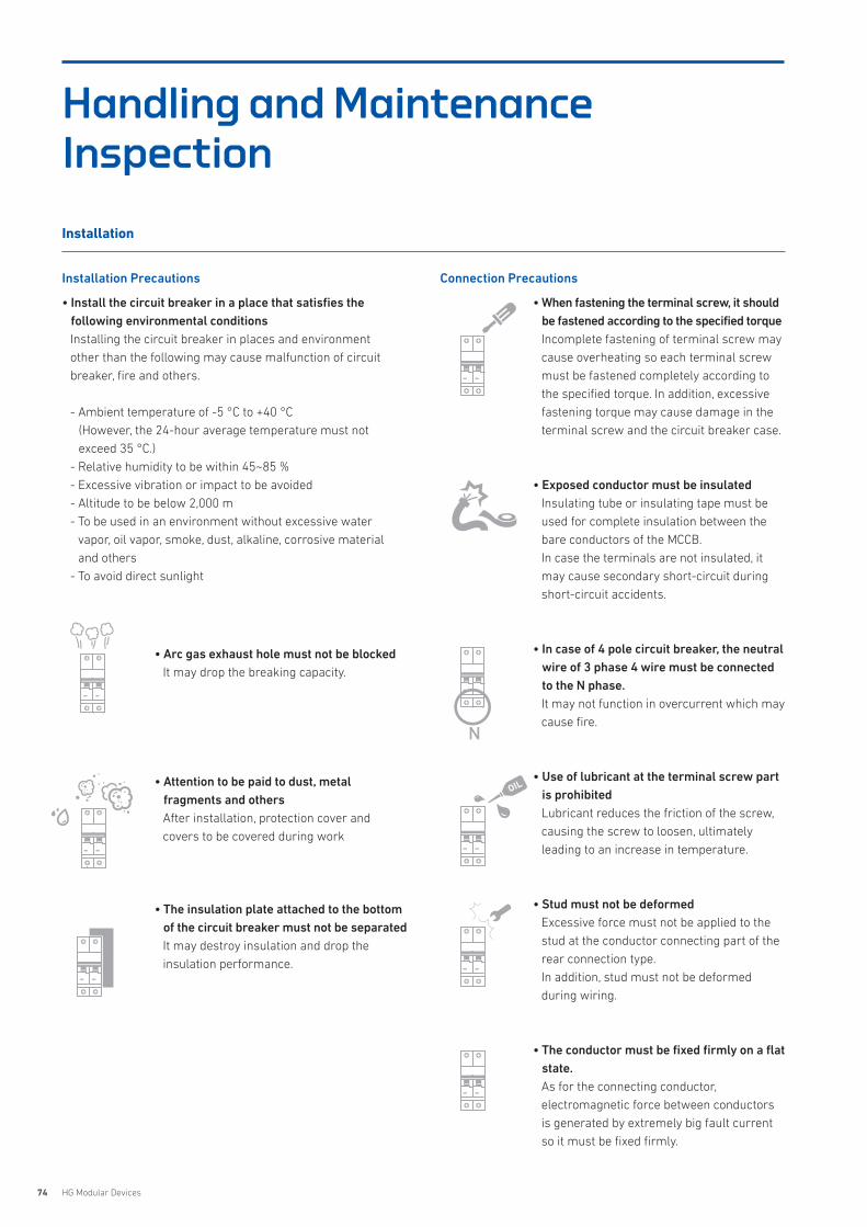
74 HG Modular Devices
Installation
Installation Precautions Connection Precautions
• Install the circuit breaker in a place that satisfies the following environmental conditionsInstalling the circuit breaker in places and environment other than the following may cause malfunction of circuit breaker, fire and others.
- Ambient temperature of -5 °C to +40 °C(However, the 24-hour average temperature must not exceed 35 °C.)
- Relative humidity to be within 45~85 %- Excessive vibration or impact to be avoided- Altitude to be below 2,000 m- To be used in an environment without excessive water
vapor, oil vapor, smoke, dust, alkaline, corrosive material and others
- To avoid direct sunlight
• Arc gas exhaust hole must not be blockedIt may drop the breaking capacity.
• Attention to be paid to dust, metal fragments and othersAfter installation, protection cover and covers to be covered during work
• The insulation plate attached to the bottom of the circuit breaker must not be separatedIt may destroy insulation and drop the insulation performance.
• When fastening the terminal screw, it should be fastened according to the specified torqueIncomplete fastening of terminal screw may cause overheating so each terminal screw must be fastened completely according to the specified torque. In addition, excessive fastening torque may cause damage in the terminal screw and the circuit breaker case.
• Exposed conductor must be insulatedInsulating tube or insulating tape must be used for complete insulation between the bare conductors of the MCCB. In case the terminals are not insulated, it may cause secondary short-circuit during short-circuit accidents.
• In case of 4 pole circuit breaker, the neutral wire of 3 phase 4 wire must be connected to the N phase. It may not function in overcurrent which may cause fire.
• Use of lubricant at the terminal screw part is prohibitedLubricant reduces the friction of the screw, causing the screw to loosen, ultimately leading to an increase in temperature.
• Stud must not be deformedExcessive force must not be applied to the stud at the conductor connecting part of the rear connection type.In addition, stud must not be deformed during wiring.
• The conductor must be fixed firmly on a flat state. As for the connecting conductor, electromagnetic force between conductors is generated by extremely big fault current so it must be fixed firmly.
Handling and Maintenance Inspection
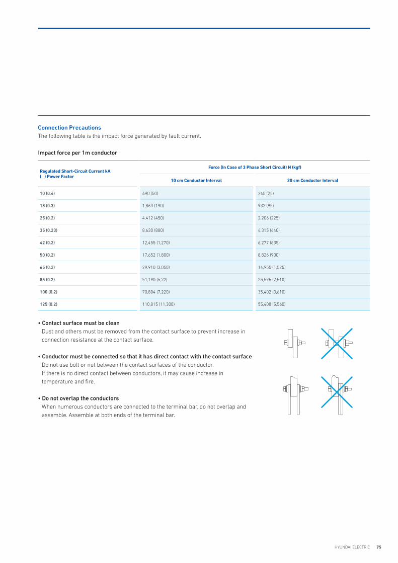
75HYUNDAI ELECTRIC
Impact force per 1m conductor
Connection PrecautionsThe following table is the impact force generated by fault current.
• Contact surface must be cleanDust and others must be removed from the contact surface to prevent increase in connection resistance at the contact surface.
• Conductor must be connected so that it has direct contact with the contact surfaceDo not use bolt or nut between the contact surfaces of the conductor.If there is no direct contact between conductors, it may cause increase in temperature and fire.
• Do not overlap the conductorsWhen numerous conductors are connected to the terminal bar, do not overlap and assemble. Assemble at both ends of the terminal bar.
Regulated Short-Circuit Current kA( ) Power Factor
Force (In Case of 3 Phase Short Circuit) N (kgf)
10 cm Conductor Interval 20 cm Conductor Interval
10 (0.4) 490 (50) 245 (25)
18 (0.3) 1,863 (190) 932 (95)
25 (0.2) 4,412 (450) 2,206 (225)
35 (0.23) 8,630 (880) 4,315 (440)
42 (0.2) 12,455 (1,270) 6,277 (635)
50 (0.2) 17,652 (1,800) 8,826 (900)
65 (0.2) 29,910 (3,050) 14,955 (1,525)
85 (0.2) 51,190 (5,22) 25,595 (2,510)
100 (0.2) 70,804 (7,220) 35,402 (3,610)
125 (0.2) 110,815 (11,300) 55,408 (5,560)
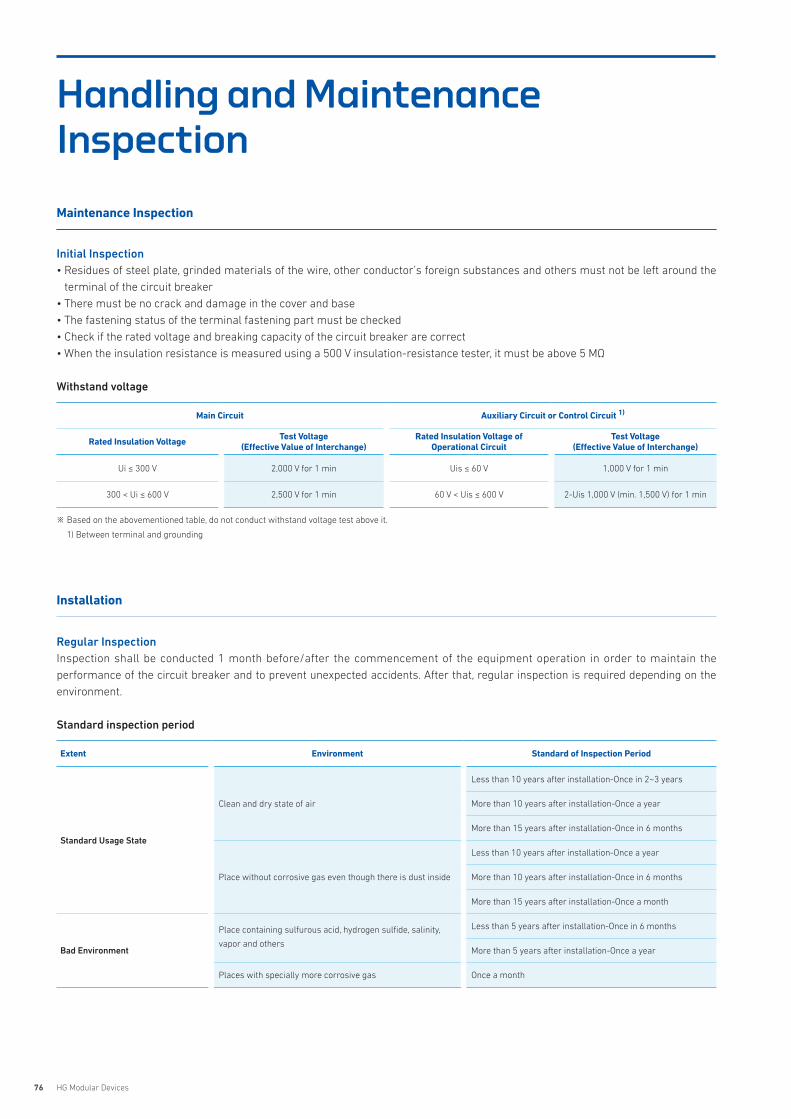
76 HG Modular Devices
Maintenance Inspection
Initial Inspection• Residues of steel plate, grinded materials of the wire, other conductor’s foreign substances and others must not be left around the
terminal of the circuit breaker• There must be no crack and damage in the cover and base• The fastening status of the terminal fastening part must be checked• Check if the rated voltage and breaking capacity of the circuit breaker are correct• When the insulation resistance is measured using a 500 V insulation-resistance tester, it must be above 5 MΩ
Withstand voltage
Regular InspectionInspection shall be conducted 1 month before/after the commencement of the equipment operation in order to maintain the performance of the circuit breaker and to prevent unexpected accidents. After that, regular inspection is required depending on the environment.
Standard inspection period
Main Circuit Auxiliary Circuit or Control Circuit 1)
Rated Insulation Voltage Test Voltage(Effective Value of Interchange)
Rated Insulation Voltage of Operational Circuit
Test Voltage(Effective Value of Interchange)
Ui ≤ 300 V 2,000 V for 1 min Uis ≤ 60 V 1,000 V for 1 min
300 < Ui ≤ 600 V 2,500 V for 1 min 60 V < Uis ≤ 600 V 2-Uis 1,000 V (min. 1,500 V) for 1 min
※ Based on the abovementioned table, do not conduct withstand voltage test above it.
1) Between terminal and grounding
Installation
Extent Environment Standard of Inspection Period
Standard Usage State
Clean and dry state of air
Less than 10 years after installation-Once in 2~3 years
More than 10 years after installation-Once a year
More than 15 years after installation-Once in 6 months
Place without corrosive gas even though there is dust inside
Less than 10 years after installation-Once a year
More than 10 years after installation-Once in 6 months
More than 15 years after installation-Once a month
Bad Environment
Place containing sulfurous acid, hydrogen sulfide, salinity,
vapor and others Less than 5 years after installation-Once in 6 months
More than 5 years after installation-Once a year
Places with specially more corrosive gas Once a month
Handling and Maintenance Inspection
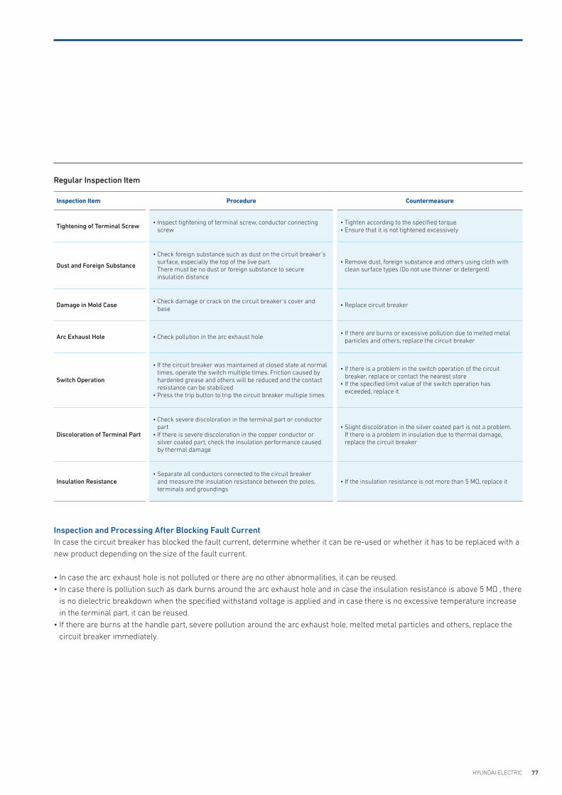
77HYUNDAI ELECTRIC
Regular Inspection Item
Inspection Item Procedure Countermeasure
Tightening of Terminal Screw • Inspect tightening of terminal screw, conductor connecting screw
• Tighten according to the specified torque• Ensure that it is not tightened excessively
Dust and Foreign Substance
• Check foreign substance such as dust on the circuit breaker’s surface, especially the top of the live part.There must be no dust or foreign substance to secure insulation distance
• Remove dust, foreign substance and others using cloth with clean surface types (Do not use thinner or detergent)
Damage in Mold Case • Check damage or crack on the circuit breaker’s cover and base
• Replace circuit breaker
Arc Exhaust Hole • Check pollution in the arc exhaust hole• If there are burns or excessive pollution due to melted metal
particles and others, replace the circuit breaker
Switch Operation
• If the circuit breaker was maintained at closed state at normal times, operate the switch multiple times. Friction caused by hardened grease and others will be reduced and the contact resistance can be stabilized
• Press the trip button to trip the circuit breaker multiple times
• If there is a problem in the switch operation of the circuit breaker, replace or contact the nearest store
• If the specified limit value of the switch operation has exceeded, replace it
Discoloration of Terminal Part
• Check severe discoloration in the terminal part or conductor part
• If there is severe discoloration in the copper conductor or silver coated part, check the insulation performance caused by thermal damage
• Slight discoloration in the silver coated part is not a problem.If there is a problem in insulation due to thermal damage, replace the circuit breaker
Insulation Resistance• Separate all conductors connected to the circuit breaker
and measure the insulation resistance between the poles, terminals and groundings
• If the insulation resistance is not more than 5 MΩ, replace it
Inspection and Processing After Blocking Fault CurrentIn case the circuit breaker has blocked the fault current, determine whether it can be re-used or whether it has to be replaced with a new product depending on the size of the fault current.
• In case the arc exhaust hole is not polluted or there are no other abnormalities, it can be reused. • In case there is pollution such as dark burns around the arc exhaust hole and in case the insulation resistance is above 5 MΩ , there
is no dielectric breakdown when the specified withstand voltage is applied and in case there is no excessive temperature increase in the terminal part, it can be reused.
• If there are burns at the handle part, severe pollution around the arc exhaust hole, melted metal particles and others, replace the circuit breaker immediately.
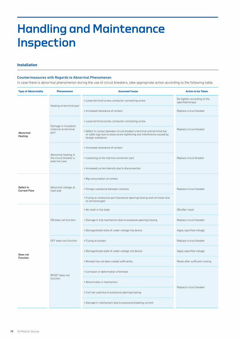
78 HG Modular Devices
Handling and Maintenance Inspection
Countermeasures with Regards to Abnormal PhenomenonIn case there is abnormal phenomenon during the use of circuit breakers, take appropriate action according to the following table.
Type of Abnormality Phenomenon Assumed Cause Action to be Taken
Abnormal Heating
Heating at terminal part
• Loose terminal screw, conductor connecting screwRe-tighten according to the specified torque
• Increased resistance of contact Replace circuit breaker
Damage in insulation material at terminal part
• Loose terminal screw, conductor connecting screw
Replace circuit breaker• Defect in contact between circuit breaker’s terminal and terminal bar
or cable lugs due to loose screw tightening and interference caused by foreign substance
Abnormal heating in the circuit breaker’s external case
• Increased resistance of contact
Replace circuit breaker• Loosening at the internal connection part
• Increased current density due to disconnection
Defect in Current Flow
Abnormal voltage at load side
• Big consumption at contact
Replace circuit breaker• Foreign substance between contacts
• Fusing at conductive part (excessive opening/closing and corrosion due to corrosive gas)
Does not Function
ON does not function
• No reset in trip state ON after reset
• Damage in trip mechanism due to excessive opening/closing Replace circuit breaker
• Demagnetized state of under-voltage trip device Apply specified voltage
OFF does not function • Fusing at contact Replace circuit breaker
RESET does not function
• Demagnetized state of under-voltage trip device Apply specified voltage
• Bimetal has not been cooled sufficiently Reset after sufficient cooling
• Corrosion or deformation of bimetal
Replace circuit breaker
• Abnormality in mechanism
• Can’t be used due to excessive opening/closing
• Damage in mechanism due to excessive breaking current
Installation
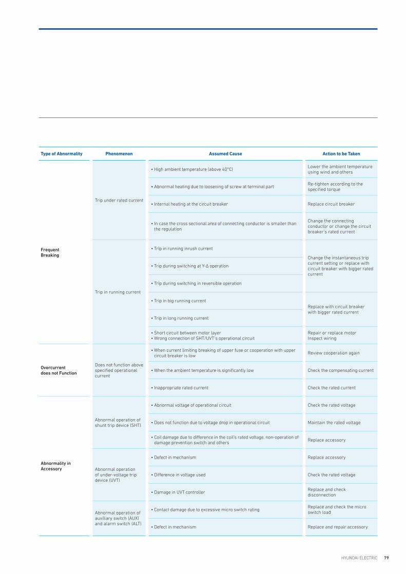
79HYUNDAI ELECTRIC
Type of Abnormality Phenomenon Assumed Cause Action to be Taken
FrequentBreaking
Trip under rated current
• High ambient temperature (above 40°C)Lower the ambient temperature using wind and others
• Abnormal heating due to loosening of screw at terminal part Re-tighten according to the specified torque
• Internal heating at the circuit breaker Replace circuit breaker
• In case the cross sectional area of connecting conductor is smaller than the regulation
Change the connecting conductor or change the circuit breaker’s rated current
Trip in running current
• Trip in running inrush current
Change the instantaneous trip current setting or replace with circuit breaker with bigger rated current
• Trip during switching at Y-� operation
• Trip during switching in reversible operation
• Trip in big running currentReplace with circuit breaker with bigger rated current
• Trip in long running current
• Short circuit between motor layer • Wrong connection of SHT/UVT’s operational circuit
Repair or replace motorInspect wiring
Overcurrent does not Function
Does not function above specified operational current
• When current limiting breaking of upper fuse or cooperation with upper circuit breaker is low
Review cooperation again
• When the ambient temperature is significantly low Check the compensating current
• Inappropriate rated current Check the rated current
Abnormality in Accessory
Abnormal operation of shunt trip device (SHT)
• Abnormal voltage of operational circuit Check the rated voltage
• Does not function due to voltage drop in operational circuit Maintain the rated voltage
• Coil damage due to difference in the coil’s rated voltage, non-operation of damage prevention switch and others
Replace accessory
Abnormal operation of under-voltage trip device (UVT)
• Defect in mechanism Replace accessory
• Difference in voltage used Check the rated voltage
• Damage in UVT controllerReplace and check disconnection
Abnormal operation of auxiliary switch (AUX) and alarm switch (ALT)
• Contact damage due to excessive micro switch ratingReplace and check the micro switch load
• Defect in mechanism Replace and repair accessory
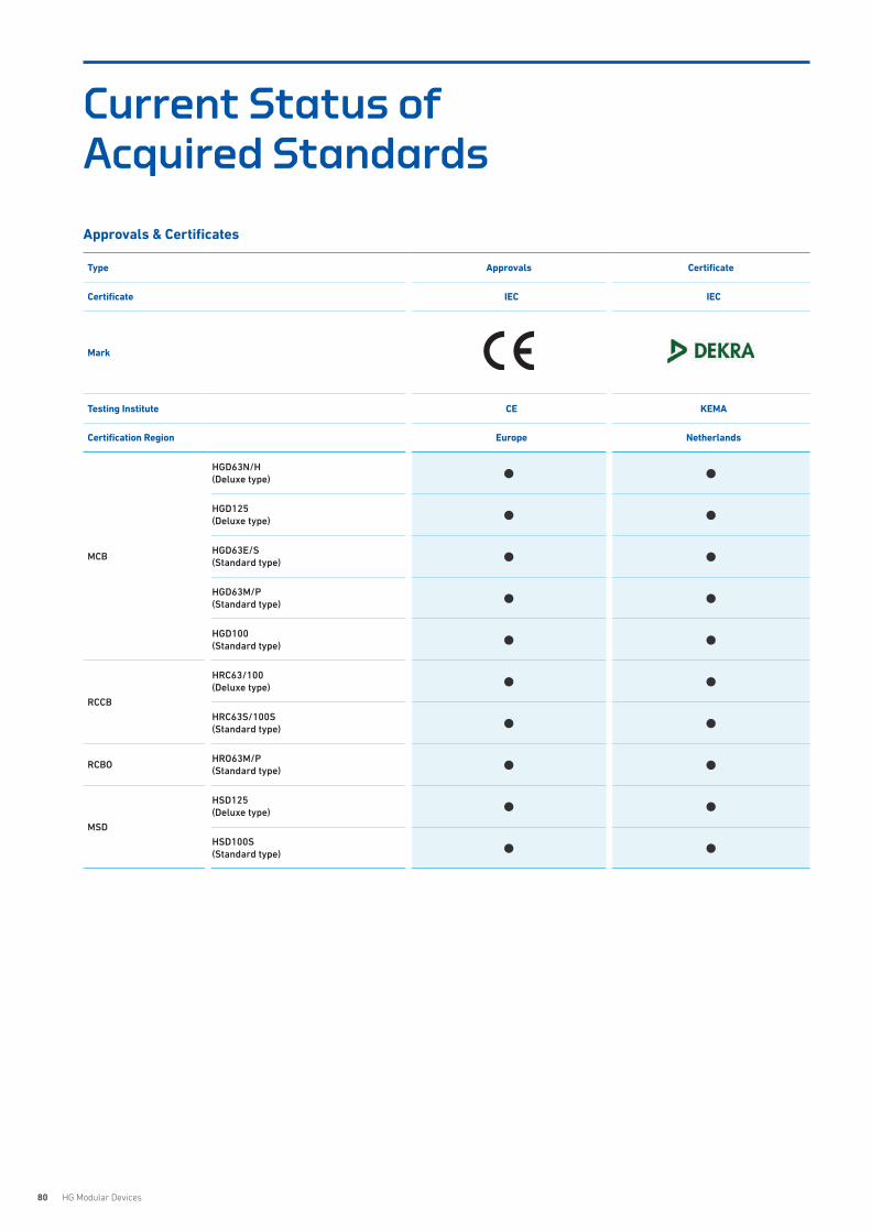
80 HG Modular Devices
Current Status of Acquired Standards
Approvals & Certificates
Type Approvals Certificate
Certificate IEC IEC
Mark
Testing Institute CE KEMA
Certification Region Europe Netherlands
MCB
HGD63N/H(Deluxe type) ● ●
HGD125(Deluxe type) ● ●
HGD63E/S(Standard type) ● ●
HGD63M/P(Standard type) ● ●
HGD100(Standard type) ● ●
RCCB
HRC63/100(Deluxe type) ● ●
HRC63S/100S(Standard type) ● ●
RCBOHRO63M/P(Standard type) ● ●
MSD
HSD125(Deluxe type) ● ●
HSD100S(Standard type) ● ●

www.hyundai-electric.com
KOREA
Headquarter (Financial)
Hyundai Bldg, 75, Yulgok-ro, Jongno-gu, Seoul, Korea Tel: +82-2-746-7646 / Fax: +82-2-746-7441
Sales & Marketing(Seongnam)
5th Floor 55, Bundang-ro, Bundang-gu, Seongnam-si, Gyeonggi-do, Korea Tel: +82-31-8006-6780 / Fax: +82-31-8006-6898
Main Factory(Ulsan)
700, Bangeojinsunhwan-doro, Dong-gu, Ulsan, Korea Tel: +82-52-202-8114 / Fax: +82-52-202-8010
Seonam Factory(Ulsan)
223, Sapyong-ro, Nam-gu, Ulsan, Korea Tel: +82-52-202-8114
R&D Center(Yongin)
17-10, Mabuk-ro 240beon-gil, Giheung-gu, Yongin-si, Gyeonggi-do, Korea Tel: +82-31-289-5114 / Fax: +82-31-289-5040
OVERSEAS
Branch Offices
U.S.A(Atlanta)
6100 Atlantic Boulevard, 2nd FL., Norcross, GA30071, U.S.ATel: +1-678-823-7839 / Fax: +1-678-823-7553
Japan (Osaka)
5th Floor Nagahori Plaza Bldg. 2-4-8 Minami Senba, Chuo-ku, Osaka 542-0081, Japan Tel: +81-6-6261-5766~7 / Fax: +81-6-6261-5818
Saudi Arabia(Riyadh)
Office number 404, 4th floor,Akaria-3 building, Olaya street, P.O Box 8072, Riyadh, 11482, Kindom of Saudi Arabia Tel: +966-11-464-4696, 9366 / Fax: +966-11-462-2352
Russia(Moscow)
World Trade Center, Ent.3, #703, Krasnopresnenskaya Nab.12, Moscow, 123610, RussiaTel: +7-495-258-1381
U.A.E(Dubai)
Unit 205, Emaar Square Building No.4 Sheikh Zayed Road, Dubai 252458, U.A.ETel: +971-4-425-7995 / Fax: +971-4-425-7996
Germany(Frankfurt)
Mendelssohn strabe 55-59 Frankfurt 60325, GermanyTel: +49-69-4699-4988
Thailand(Bangkok)
19th Floor, Unit 1908, Sathorn Square Office Tower, 98 North Sathorn Road, Silom, Bangrak, Bangkok 10500, Thailand Tel: +66-02-115-7920 / Fax: +66-2-115-7898
Subsidiaries
U.S.A(Alabama)
215 Folmar Parkway, Montgomery, AL 36105, U.S.A.Tel: +1-334-481-2000 / Fax: +1-334-481-2098
Bulgaria(Sofia)
41, Rojen Blvd., 1271 Sofia, BulgariaTel: +359-2-803-3200, 3210, 3220 / Fax: +359-2-803-3203, 3242
China(Yangzhong)
No.9, Xiandai Road, Xinba Scientific and Technologic Zone, Yangzhong, Jiangsu, P.R.C. Zip:212212, China Tel: +86-511-8842-0666, 0500 / Fax: +86-511-8842-0668, 0231
India(Anantapur)
5-289-4, Near Aimuktheeshwara Temple, Penukonda Mandal, Penukonda, Anantapur Dist, Andhrapradesh-515110, India Tel: +91-93982-5137
R&D Centers
Hungary(Budapest)
Hyundai Technologies Center Hungary ltd., 1146, Budapest, Hermina ut 22, HungaryTel: +36-1-273-3733 / Fax: +36-1-220-6708
China(Shanghai)
Room 10102, Building 10, No.498, Guoshoujing Road, Pudong, Shanghai, ChinaTel: +86-21-5013-3393 #108 / Fax: +86-21-5013-3393 #105
Switzerland(Zurich)
Hardturmstrasse 135, CH-8005, Zurich, SwitzerlandTel: +41-44-527-0-56


![Index [3.imimg.com] · Index Miniature Circuit Breaker 2 Residual Current Circuit Breaker (RCCB) 16A - 63A 36 Miniature Circuit Breaker (80A - 125A) 18 ... until it operates a latching](https://img.pdfslide.us/doc/110x75/5e8f8e0a5f8a0f4fe028da5f/index-3imimgcom-index-miniature-circuit-breaker-2-residual-current-circuit-breaker.jpg)