Embed Size (px)
Citation preview

GE Consumer & IndustrialMultilin
LISTED
52TL
IND.CONT. EQ.
E83849
239MOTOR PROTECTION RELAY
Communications GuideFirmware Revision: 2.7x
239PC Software: 2.7x or newer
Manual P/N: 1601-9031-A1 (GEK-113398)
Copyright © 2007 GE Multilin
GE Multilin
215 Anderson Avenue, Markham, Ontario
Canada L6E 1B3
Tel: (905) 294-6222 Fax: (905) 201-2098
Internet: http://www.GEmultilin.com
*1601-0067-DC*
TRIP
ALARM
AUXILIARY
SERVICE
PICKUP
COMMUNICATE
RESET
STORE
ACTUAL
VALUE
MESSAGE
SETPOINT
239 Motor Protection Relay
CAUSE OF LAST TRIP:MECHANICAL JAM
ISO9001:2000GE MULT I L
I N
RE
GISTERED
GE Multilin’s Quality Management System is
registered to ISO9001:2000
QMI # 005094
UL # A3775

© 2007 GE Multilin Incorporated. All rights reserved.
GE Multilin 239 Motor Protection Relay Communications Guide for revision 2.7x.
239 Motor Protection Relay, is a registered trademark of GE Multilin Inc.
The contents of this manual are the property of GE Multilin Inc. This documentation is furnished on license and may not be reproduced in whole or in part without the permission of GE Multilin. The content of this manual is for informational use only and is subject to change without notice.
Part numbers contained in this manual are subject to change without notice, and should therefore be verified by GE Multilin before ordering.
Part number: 1601-9031-A1 (October 2007)

TABLE OF CONTENTS
239 MOTOR PROTECTION RELAY – COMMUNICATIONS GUIDE TOC–I
Table of Contents
COMMUNICATIONS ..........................................................................................................CG-1MODBUS PROTOCOL ........................................................................................................... CG-1ELECTRICAL INTERFACE ....................................................................................................... CG-1DATA FRAME FORMAT / DATA RATE ................................................................................ CG-2
DATA PACKET FORMAT ...................................................................................................CG-3ERROR CHECKING ............................................................................................................... CG-3TIMING .................................................................................................................................. CG-5
239 SUPPORTED MODBUS FUNCTIONS ......................................................................CG-603/04: READ SETPOINTS / ACTUAL VALUES .................................................................. CG-605: EXECUTE OPERATION .................................................................................................. CG-706: STORE SINGLE SETPOINT ............................................................................................ CG-807: READ DEVICE STATUS ................................................................................................. CG-808: LOOPBACK TEST ........................................................................................................... CG-916: STORE MULTIPLE SETPOINTS ..................................................................................... CG-10
16: PERFORMING COMMANDS ......................................................................................CG-12ERROR RESPONSES ...........................................................................................................CG-13MEMORY MAP INFORMATION ........................................................................................CG-14
USER DEFINABLE MEMORY MAP ...................................................................................... CG-14239 MEMORY MAP ............................................................................................................ CG-15MEMORY MAP DATA FORMATS ......................................................................................... CG-36

TOC–II 239 MOTOR PROTECTION RELAY – COMMUNICATIONS GUIDE
TABLE OF CONTENTS

239 MOTOR PROTECTION RELAY – COMMUNICATIONS GUIDE CG–1
239 Motor Protection Relay
Communications Guide
GE Consumer & IndustrialMultilin
TRIP
ALARM
AUXILIARY
SERVICE
PICKUP
COMMUNICATE
RESET
STORE
ACTUAL
VALUE
MESSAGE
SETPOINT
239 Motor Protection Relay
CAUSE OF LAST TRIP:MECHANICAL JAM
Communications Guide
CG.1 Communications
CG.1.1 Modbus Protocol
The GE Multilin 239 implements a subset of the AEG Modicon Modbus RTU serial communication standard. Many popular programmable controllers support this protocol directly with a suitable interface card allowing direct connection of relays. Although the Modbus protocol is hardware independent, the 239 interface uses a 2 wire RS485 hardware interface. Modbus is a single master multiple slave protocol suitable for a multi-drop configuration as provided by RS485 hardware. In this configuration up to 32 slaves can be daisy-chained together on a single communication channel.
The GE Multilin 239 is always a Modbus slave. It cannot be programmed as a Modbus master. Computers or PLCs are commonly programmed as masters. The Modbus protocol exists in two versions: Remote Terminal Unit (RTU, binary) and ASCII. Only the RTU version is supported by the 239. Monitoring, programming and control functions are possible using read and write register commands.
CG.1.2 Electrical Interface
The hardware or electrical interface is two-wire RS485. In a two-wire RS485 link data flow is bi-directional and half duplex. That is, data is never transmitted and received at the same time. RS485 lines should be connected in a daisy chain configuration (avoid star connections) with a terminating network installed at each end of the link, i.e. at the master end and at the slave farthest from the master. The terminating network should consist of a 120 Ω resistor in series with a 1 nF ceramic capacitor when used with Belden 9841 RS485 wire. The value of the terminating resistors should be equal to the characteristic impedance of the line. This is approximately 120 Ω for standard #22 AWG twisted pair wire. Shielded wire should always be used to minimize noise. Polarity

CG–2 239 MOTOR PROTECTION RELAY – COMMUNICATIONS GUIDE
COMMUNICATIONS GUIDE
is important in RS485 communications. Each '+' terminal of every device must be connected together for the system to operate. See Section 2.1.3 in the 239 Instruction Manual for details on correct serial port wiring.
CG.1.3 Data Frame Format / Data Rate
One data frame of an asynchronous transmission to or from a 239 consists of 1 start bit, 8 data bits, and 1 stop bit. This produces a 10 bit data frame. This is important for transmission through modems at high bit rates (11 bit data frames are not supported by Hayes modems at bit rates of greater than 300 bps).
Modbus protocol can be implemented at any standard communication speed. The 239 supports operation at 1200, 2400, 4800, 9600, and 19200 baud.

COMMUNICATIONS GUIDE
239 MOTOR PROTECTION RELAY – COMMUNICATIONS GUIDE CG–3
CG.2 Data Packet Format
A complete request/response sequence consists of the following bytes (transmitted as separate data frames):
Master Request Transmission:
SLAVE ADDRESS -1 byteFUNCTION CODE -1 byteDATA variable number of bytes depending on
FUNCTION CODECRC 2 bytes
Slave Response Transmission:
SLAVE ADDRESS -1 byteFUNCTION CODE -1 byteDATA variable number of bytes depending on
FUNCTION CODECRC 2 bytes
• SLAVE ADDRESS: This is the first byte of every transmission. This byte represents the user-assigned address of the slave device that is to receive the message sent by the master. Each slave device must be assigned a unique address and only the addressed slave will respond to a transmission that starts with its address. In a master request transmission the SLAVE ADDRESS represents the address of the slave to which the request is being sent. In a slave response transmission the SLAVE ADDRESS represents the address of the slave that is sending the response. Note: A master transmission with a SLAVE ADDRESS of 0 indicates a broadcast command. Broadcast commands can be used only in certain situations; see APPLICATIONS for details.
• FUNCTION CODE: This is the second byte of every transmission. Modbus defines function codes of 1 to 127. The 239 implements some of these functions. See section 3 for details of the supported function codes. In a master request transmission the FUNCTION CODE tells the slave what action to perform. In a slave response transmission if the FUNCTION CODE sent from the slave is the same as the FUNCTION CODE sent from the master then the slave performed the function as requested. If the high order bit of the FUNCTION CODE sent from the slave is a 1 (i.e. if the FUNCTION CODE is > 127) then the slave did not perform the function as requested and is sending an error or exception response.
• DATA: This will be a variable number of bytes depending on the FUNCTION CODE. This may be Actual Values, Setpoints, or addresses sent by the master to the slave or by the slave to the master. See section 3 for a description of the supported functions and the data required for each.
• CRC: This is a two byte error checking code.
CG.2.1 Error Checking
The RTU version of Modbus includes a two byte CRC-16 (16 bit cyclic redundancy check) with every transmission. The CRC-16 algorithm essentially treats the entire data stream (data bits only; start, stop and parity ignored) as one continuous binary

CG–4 239 MOTOR PROTECTION RELAY – COMMUNICATIONS GUIDE
COMMUNICATIONS GUIDE
number. This number is first shifted left 16 bits and then divided by a characteristic polynomial (11000000000000101B). The 16 bit remainder of the division is appended to the end of the transmission, LSByte first. The resulting message including CRC, when divided by the same polynomial at the receiver will give a zero remainder if no transmission errors have occurred.
If a 239 Modbus slave device receives a transmission in which an error is indicated by the CRC-16 calculation, the slave device will not respond to the transmission. A CRC-16 error indicates that one or more bytes of the transmission were received incorrectly and thus the entire transmission should be ignored in order to avoid the 239 performing any incorrect operation.
The CRC-16 calculation is an industry standard method used for error detection. An algorithm is included here to assist programmers in situations where no standard CRC-16 calculation routines are available.
CRC-16 ALGORITHM:
Once the following algorithm is complete, the working register "A" will contain the CRC value to be transmitted. Note that this algorithm requires the characteristic polynomial to be reverse bit ordered. The MSbit of the characteristic polynomial is dropped since it does not affect the value of the remainder. The following symbols are used in the algorithm:
--> data transferA16 bit working registerAL low order byte of AAH high order byte of ACRC 16 bit CRC-16 valuei,j loop counters(+) logical exclusive-or operatorDi i-th data byte (i = 0 to N-1)G 16 bit characteristic polynomial = 1010000000000001 with MSbit
dropped and bit order reversed
shr(x) shift right (the LSbit of the low order byte of x shifts into a carry flag, a '0' is shifted into the MSbit of the high order byte of x, all other bits shift right one location
The algorithm:
1. FFFF hex --> A
2. 0 --> i
3. 0 --> j
4. Di (+) AL --> AL
5. j+1 --> j
6. shr(A)
7. is there a carry? No: go to 8.Yes: G (+) A --> A

COMMUNICATIONS GUIDE
239 MOTOR PROTECTION RELAY – COMMUNICATIONS GUIDE CG–5
8. is j = 8? No: go to 5.Yes: go to 9.
9. i+1 --> i
10. is i = N? No: go to 3.Yes: go to 11.
11. A --> CRC
CG.2.2 Timing
Data packet synchronization is maintained by timing constraints. The receiving device must measure the time between the reception of characters. If three and one half character times elapse without a new character or completion of the packet, then the communication link must be reset (i.e. all slaves start listening for a new transmission from the master). Thus at 9600 baud a delay of greater than 3.5 * 1/9600 * 10 = 3.65 ms will cause the communication link to be reset.

CG–6 239 MOTOR PROTECTION RELAY – COMMUNICATIONS GUIDE
COMMUNICATIONS GUIDE
CG.3 239 Supported Modbus Functions
The following functions are supported by the 239:
• 03 - Read Setpoints and Actual Values
• 04 - Read Setpoints and Actual Values
• 05 - Execute Operation
• 06 - Store Single Setpoint
• 07 - Read Device Status
• 08 - Loopback Test
• 16 - Store Multiple Setpoints
CG.3.1 03/04: Read Setpoints / Actual Values• Modbus implementation: Read Input and Holding Registers
• 239 Implementation: Read Setpoints and Actual Values
These commands can be used to read any Setpoint ("holding registers") or Actual Value ("input registers"). Holding and input registers are 16-bit (two byte) values transmitted low order byte first. Thus all 239 Setpoints and Actual Values are sent as two bytes. The maximum number of registers that can be read in one transmission is 125. Function codes 03 and 04 are configured to read setpoints or actual values interchangeably because some PLCs do not support both of them.
The slave response to these function codes is the slave address, function code, a count of the data bytes to follow, the data itself, and the CRC. Each data item is sent as a two byte number with the low order byte sent first.
MESSAGE FORMAT AND EXAMPLE
Request slave 11 to respond with 3 registers starting at address 006B.For this example the register data in these addresses is:
Address Data006B 0000006C 0000006D 0000
Master Transmission Bytes Example (hex)
SLAVE ADDRESS - 1 byte 11 message for slave 11
FUNCTION CODE - 1 byte 03 read registersDATA STARTING ADDRESS - 2 bytes 00 6B data starting at 006BNUMBER OF SETPOINTS - 2 bytes 00 03 3 registers – 6 bytes
total
CRC - 2 bytes 76 87 CRC calculated by the master
Slave Response Bytes Example (hex)
SLAVE ADDRESS - 1 byte 11 message from slave 11

COMMUNICATIONS GUIDE
239 MOTOR PROTECTION RELAY – COMMUNICATIONS GUIDE CG–7
FUNCTION CODE - 1 byte 03 read registersBYTE COUNT - 1 byte 06 3 registers = 6 bytes
DATA 1 - 2 byte 00 00 bit set corresponding to command 13
DATA 2 - 2 bytes 00 00 value in address 006CDATA 3 - 2 bytes 00 00 value in address 006D
CRC - 2 bytes EC B5 CRC calculated by slave
CG.3.2 05: Execute Operation• Modbus Implementation: Force Single Coil
• 239 Implementation: Execute Operation
This function code allows the master to request a 239 to perform specific command operations. The command numbers listed in the Commands area of the memory map correspond to operation code for function code 05.
The operation commands can also be initiated by writing to the Commands area of the memory map using function code 16. Refer to Section CG.4: 16: Performing Commands on page –12 for complete details.
MESSAGE FORMAT AND EXAMPLE
Reset 239 (operation code 1).
Master Transmission Bytes Example (hex)
SLAVE ADDRESS - 1 byte 11 message for slave 11FUNCTION CODE - 1 byte 05 execute operation
OPERATION CODE - 2 bytes 00 01 reset command (operation code 1)
CODE VALUE - 2 bytes FF 00 perform function
CRC - 2 bytes DF 6A CRC calculated by the master
Slave Response Bytes Example (hex)
SLAVE ADDRESS - 1 byte 11 message from slave 11FUNCTION CODE - 1 byte 05 execute operation
OPERATION CODE - 2 bytes 00 01 reset command (operation code 1)
CODE VALUE - 2 bytes FF 00 perform functionCRC - 2 bytes DF 6A CRC calculated by slave
CG.3.3 06: Store Single Setpoint• Modbus Implementation: Preset Single Register
• 239 Implementation: Store Single Setpoint

CG–8 239 MOTOR PROTECTION RELAY – COMMUNICATIONS GUIDE
COMMUNICATIONS GUIDE
This command allows the master to store a single setpoint into the memory of a 239. The slave response to this function code is to echo the entire master transmission.
a) MESSAGE FORMAT AND EXAMPLE
Request slave 11 to store the value 0064 in Setpoint address 1020.
After the transmission in this example is complete, Setpoints address 1020 will contain the value 0064.
Master Transmission Bytes Example (hex)
SLAVE ADDRESS - 1 byte 11 message for slave 11
FUNCTION CODE - 1 byte 06 store single setpointDATA STARTING ADDRESS - 2 bytes 10 20 Setpoint address 1020DATA - 2 bytes 00 64 data for address 1020
CRC - 2 bytes 8F CRC calculated by the master
BB
Slave Response Bytes Example (hex)
SLAVE ADDRESS - 1 byte 11 message from slave 11
FUNCTION CODE - 1 byte 06 store single SetpointDATA STARTING ADDRESS - 2 bytes 10 20 Setpoint address 1020DATA - 2 bytes 00 64 data stored in address
1020
CRC - 2 bytes 8F BB CRC calculated by slave
CG.3.4 07: Read Device Status• Modbus Implementation: Read Exception Status
• 239 Implementation: Read Device Status
This is a function used to quickly read the status of a selected device. A short message length allows for rapid reading of status. The status byte returned will have individual bits set to 1 or 0 depending on the status of the slave device.
239 General Status Byte:
LSBit B0: Alarm condition = 1
B1: Trip condition = 1
B2: Internal fault = 1
B3: Not used
B4: Not used
B5: Not used
B6: Not used
MSBit B7: Not used

COMMUNICATIONS GUIDE
239 MOTOR PROTECTION RELAY – COMMUNICATIONS GUIDE CG–9
MESSAGE FORMAT AND EXAMPLE
Request status from slave 11.
Master Transmission Bytes Example (hex)
SLAVE ADDRESS - 1 byte 11 message for slave 11FUNCTION CODE - 1 byte 07 read device status
CRC - 2 bytes 8F BB CRC calculated by the master
Slave Response Bytes Example (hex)
SLAVE ADDRESS - 1 byte 11 message from slave 11FUNCTION CODE - 1 byte 07 execute operation
DEVICE STATUS - 1 byte 00 status = 00000000 in binary
CRC - 2 bytes 23 F5 CRC calculated by slave
CG.3.5 08: Loopback Test• Modbus Implementation: Loopback Test
• 239 Implementation: Loopback Test
This function is used to test the integrity of the communication link. The 239 will echo the request.

CG–10 239 MOTOR PROTECTION RELAY – COMMUNICATIONS GUIDE
COMMUNICATIONS GUIDE
MESSAGE FORMAT AND EXAMPLE
Loopback test from slave 11.
Master Transmission Bytes Example (hex)
SLAVE ADDRESS - 1 byte 11 message for slave 11FUNCTION CODE - 1 byte 08 loopback test
DIAG CODE - 2 bytes 00 00 must be 00 00DATA - 2 bytes 00 00 must be 00 00CRC - 2 bytes E0 0B CRC calculated by the
master
Slave Response Bytes Example (hex)
SLAVE ADDRESS - 1 byte 11 message from slave 11FUNCTION CODE - 1 byte 08 loopback testDIAG CODE - 2 bytes 00 00 must be 00 00
DATA - 2 bytes 00 00 must be 00 00CRC - 2 bytes E0 0B CRC calculated by slave
CG.3.6 16: Store Multiple Setpoints• Modbus Implementation: Preset Multiple Registers
• 239 Implementation: Store Multiple Setpoints
This function code allows multiple Setpoints to be stored into the 239 memory. Modbus "registers" are 16 bit (two byte) values transmitted low order byte first. Thus all 239 setpoints are sent as two bytes. The maximum number of Setpoints that can be stored in one transmission is dependent on the slave device. Modbus allows up to a maximum of 60 holding registers to be stored. The 239 response to this function code is to echo the slave address, function code, starting address, the number of Setpoints stored, and the CRC.
MESSAGE FORMAT AND EXAMPLE
Request slave 11 to store the value 0096 to Setpoint addresses 1028 and 1029. After the transmission in this example is complete, 239 slave 11 will have the following Setpoints information stored:
Address Data1028 00961029 0096
Master Transmission Bytes Example (hex)
SLAVE ADDRESS - 1 byte 11 message for slave 11FUNCTION CODE - 1 byte 10 store SetpointsDATA STARTING ADDRESS - 2 bytes 10 28 Setpoint address 1028
NUMBER OF SETPOINTS - 2 bytes 00 02 2 Setpoints (4 bytes total)
BYTE COUNT - 1 byte 04 4 bytes of data

COMMUNICATIONS GUIDE
239 MOTOR PROTECTION RELAY – COMMUNICATIONS GUIDE CG–11
DATA 1 - 2 bytes 00 96 data for address 1028DATA 2 - 2 bytes 00 96 data for address 1029
CRC - 2 bytes 09 53 CRC calculated by the master
Slave Response
SLAVE ADDRESS - 1 byte 11 message from slave 11FUNCTION CODE - 1 byte 10 store Setpoints
DATA STARTING ADDRESS - 2 bytes 10 28 Setpoint address 1028NUMBER OF SETPOINTS - 2 bytes 00 02 2 SetpointsCRC - 2 bytes C7 90 CRC calculated by slave

CG–12 239 MOTOR PROTECTION RELAY – COMMUNICATIONS GUIDE
COMMUNICATIONS GUIDE
CG.4 16: Performing Commands
Some PLCs may not support execution of commands using function code 5 but do support storing multiple setpoints using function code 16. To perform this operation using function code 16 (10H), a certain sequence of commands must be written at the same time to the 239. The sequence consists of: Command Function register, Command operation register and Command Data (if required). The Command Function register must be written with the value of 5 indicating an execute operation is requested. The Command Operation register must then be written with a valid command operation number from the list of commands shown in the memory map. The Command Data registers must be written with valid data if the command operation requires data. The selected command will execute immediately upon receipt of a valid transmission.
MESSAGE FORMAT AND EXAMPLE
Master Transmission Bytes Example (hex)
SLAVE ADDRESS - 1 byte 11 message for slave 11FUNCTION CODE - 1 byte 10 store SetpointsDATA STARTING ADDRESS - 2 bytes 00 80 Setpoint address 0080
NUMBER OF SETPOINTS - 2 bytes 00 02 2 Setpoints (4 bytes total)
BYTE COUNT - 1 byte 04 4 bytes of dataDATA 1 - 2 bytes 00 05 data for address 0080
DATA 2 - 2 bytes 00 01 data for address 0081CRC - 2 bytes 7E CE CRC calculated by the
master
Slave Response
SLAVE ADDRESS - 1 byte 11 message from slave 11
FUNCTION CODE - 1 byte 10 store SetpointsDATA STARTING ADDRESS - 2 bytes 00 Setpoint address 0080
80
NUMBER OF SETPOINTS - 2 bytes 00 02 2 SetpointsCRC - 2 bytes 42 B0 CRC calculated by slave

COMMUNICATIONS GUIDE
239 MOTOR PROTECTION RELAY – COMMUNICATIONS GUIDE CG–13
CG.5 Error Responses
When a 239 detects an error other than a CRC error, a response will be sent to the master. The MSbit of the FUNCTION CODE byte will be set to 1 (i.e. the function code sent from the slave will be equal to the function code sent from the master plus 128). The following byte will be an exception code indicating the type of error that occurred.
Transmissions received from the master with CRC errors will be ignored by the 239.
The slave response to an error (other than CRC error) will be:
SLAVE ADDRESS- 1 byteFUNCTION CODE- 1 byte (with MSbit set to 1)EXCEPTION CODE- 1 byteCRC - 2 bytes
The 239 implements the following exception response codes.
01 - ILLEGAL FUNCTIONThe function code transmitted is not one of the functions supported by the 239.
02 - ILLEGAL DATA ADDRESSThe address referenced in the data field transmitted by the master is not an allowable address for the 239.
03 - ILLEGAL DATA VALUEThe value referenced in the data field transmitted by the master is not within range for the selected data address.

CG–14 239 MOTOR PROTECTION RELAY – COMMUNICATIONS GUIDE
COMMUNICATIONS GUIDE
CG.6 Memory Map Information
The data stored in the 239 is grouped as Setpoints and Actual Values. Setpoints can be read and written by a master computer. Actual Values can be read only. All Setpoints and Actual Values are stored as two byte values. That is, each register address is the address of a two byte value. Addresses are listed in hexadecimal. Data values (Setpoint ranges, increments, factory values) are in decimal.
CG.6.1 User Definable Memory Map
The 239 contains a User Definable area in the memory map. This area allows remapping of the addresses of all Actual Values and Setpoints registers. The User Definable area has two sections:
1. A Register Index area (memory map addresses 0180H-01F7H) that contains 120 Actual Values or Setpoints register addresses.
2. A Register area (memory map addresses 0100H-0177H) that contains the data at the addresses in the Register Index.
Register data that is separated in the rest of the memory map may be remapped to adjacent register addresses in the User Definable Registers area. This is accomplished by writing to register addresses in the User Definable Register Index area. This allows for improved throughput of data and can eliminate the need for multiple read command sequences.
For example, if the values of Phase A Current (register address 0229H) and RTD 1 Celsius Temperature (register address 0240H) are required to be read from a 239, their addresses may be remapped as follows:
1. Write 0229H to address 0180H (User Definable Index 0000) using function code 06 or 16.
2. Write 0240H to address 0181H (User Definable Index 0001) using function code 06 or 16.
A read (function code 03 or 04) of registers 0100H (User Definable Register 0000) and 0101H (User Definable Register 0001) will return the Phase A Current and RTD 1 Celsius Temperature.

COMMUNICATIONS GUIDE
239 MOTOR PROTECTION RELAY – COMMUNICATIONS GUIDE CG–15
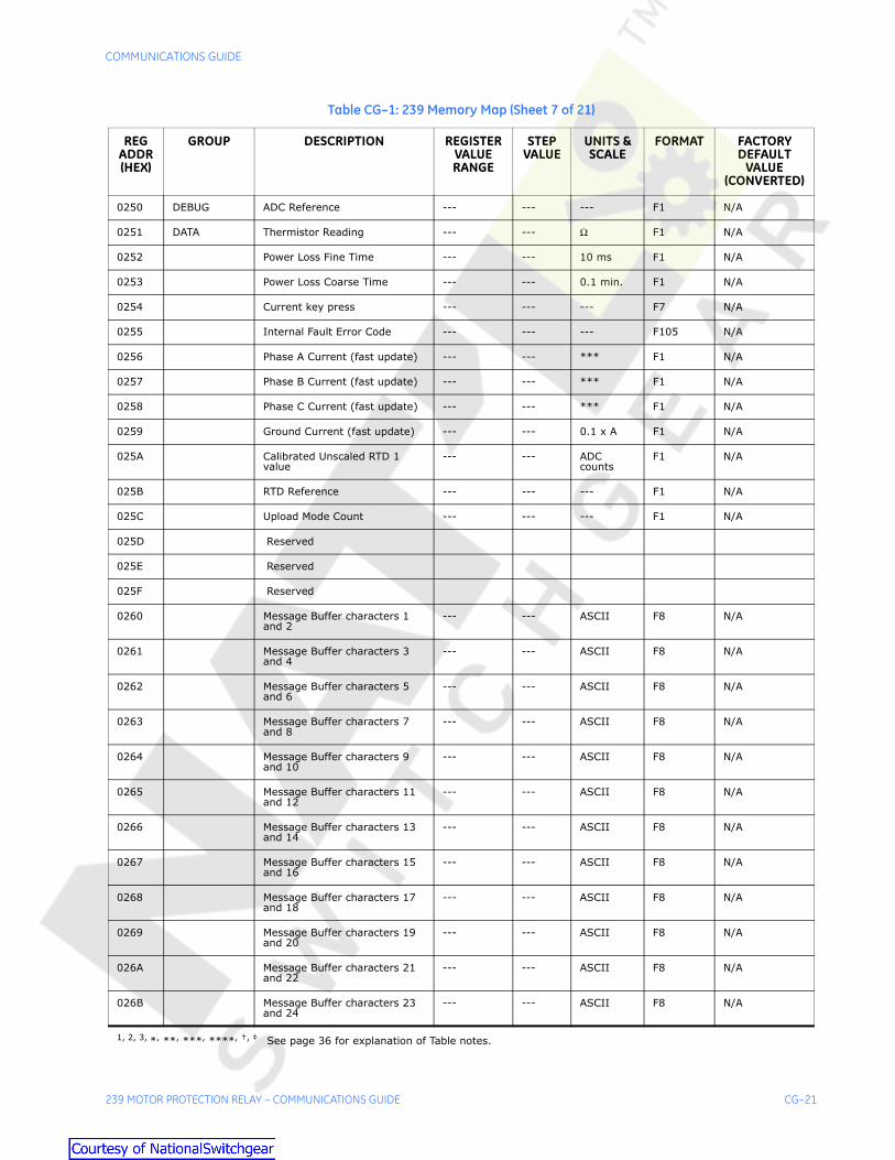
CG.6.2 239 Memory Map
Table CG–1: 239 Memory Map (Sheet 1 of 21)
REG ADDR (HEX)
GROUP DESCRIPTION REGISTER VALUE RANGE
STEP VALUE
UNITS & SCALE
FORMAT FACTORY DEFAULT
VALUE (CONVERTED)
Product Information (Input Registers) Addresses – 0000 to 007F
0000 PRODUCTID
GE Multilin Product Device Code
--- --- --- F1 64
0001 Hardware Version Code --- --- --- F3 current version
0002 Main Software Version Code --- --- --- F1 current version
0003 Modification File Number 1 --- --- --- F1 mod. file number 1
0004 Boot Software Version Code --- --- --- F1 current version
0005 Supervisor Processor Version Code
--- --- --- F1 current version
0006 GE Multilin product options --- --- --- F104 from order code
0007 Modification File Number 2 --- --- --- F1 mod. file number 2
0008 Modification File Number 3 --- --- --- F1 mod. file number 3
0009 Modification File Number 4 --- --- --- F1 mod. file number 4
000A Modification File Number 5 --- --- --- F1 mod. file number 5
000B Main Version Month, Day --- --- --- F40
000C Main Version Year --- --- --- F41
000D Supervisor Revision Month, Day
--- --- --- F40
000E Supervisor Revision Year --- --- --- F41
000F Boot Revision Month, Day --- --- --- F40
0010 Boot Revision Year --- --- --- F41
0011 Reserved
↓ ↓
001F Reserved
0020 Serial Number characters 1 and 2
--- --- ASCII F8 1st, 2nd char.
0021 Serial Number characters 3 and 4
--- --- ASCII F8 3rd, 4th char.
0022 Serial Number characters 5 and 6
--- --- ASCII F8 5th, 6th char
0023 Serial Number characters 7 and 8
--- --- ASCII F8 7th, 8th char.
0024 Reserved
↓ ↓
1, 2, 3, *, **, ***, ****, †, ‡ See page 36 for explanation of Table notes.

CG–16 239 MOTOR PROTECTION RELAY – COMMUNICATIONS GUIDE
COMMUNICATIONS GUIDE
002F Reserved
0030 Calibration Day --- --- --- F1 day of calibration
0031 Calibration Month --- --- --- F109 month of calibration
0032 Calibration Year --- --- --- F1 year of calibration
0033 Reserved
↓ ↓
003F Reserved
0040 Manufacture Day --- --- --- F1 day of manufacture
0041 Manufacture Month --- --- --- F109 month of manufacture
0042 Manufacture Year --- --- --- F1 yr. of manufacture
0043 Reserved
↓ ↓
007F Reserved
Commands (Holding Registers) Addresses – 0080 to 00FF
0080 COMMANDS Command Function Code 5 --- --- F1 5
0081 Command Operation Code 1-13 1 --- F27 0
0082 Command Data 1 0-65535 1 --- F8,F28F30
0
0083 Command Data 2 0-65535 1 --- F31 0
0084 Command Data 3 0-65535 1 --- F8 0
0085 Command Data 4 0-65535 1 --- F8 0
0086 Command Data 5 0-65535 1 --- F8 0
0087 Command Data 6 0-65535 1 --- F8 0
0088 Command Data 7 0-65535 1 --- F8 0
0089 Command Data 8 0-65535 1 --- F8 0
008A Command Data 9 0-65535 1 --- F8 0
008B Command Data 10 0-65535 1 --- F8 0
008C Command Data 11 0-65535 1 --- F8 0
008D Reserved
008E Reserved
008F Reserved
Table CG–1: 239 Memory Map (Sheet 2 of 21)
REG ADDR (HEX)
GROUP DESCRIPTION REGISTER VALUE RANGE
STEP VALUE
UNITS & SCALE
FORMAT FACTORY DEFAULT
VALUE (CONVERTED)
1, 2, 3, *, **, ***, ****, †, ‡ See page 36 for explanation of Table notes.

COMMUNICATIONS GUIDE
239 MOTOR PROTECTION RELAY – COMMUNICATIONS GUIDE CG–17
0090 Reserved
↓ ↓
00FF Reserved
User Definable Register (Input Registers) Addresses – 0100 to 017F
0100 USERDEFINABLEREGISTERS
User Definable Data 0000 --- --- --- --- ---
0101 User Definable Data 0001 --- --- --- --- ---
0102 User Definable Data 0002 --- --- --- --- ---
0103 User Definable Data 0003 --- --- --- --- ---
0104 User Definable Data 0004 --- --- --- --- ---
0105 User Definable Data 0005 --- --- --- --- ---
0106 User Definable Data 0006 --- --- --- --- ---
0107 User Definable Data 0007 --- --- --- --- ---
0108 User Definable Data 0008 --- --- --- --- ---
0109 User Definable Data 0009 --- --- --- --- ---
010A User Definable Data 000A --- --- --- --- ---
010B User Definable Data 000B --- --- --- --- ---
↓ ↓ ↓ ↓ ↓ ↓ ↓
0177 User Definable Data 0077 --- --- --- --- ---
0178 Reserved
↓ ↓
017F Reserved
User Definable Register Index (Holding Registers) Addresses – 0180 to 01FF
0180 USERDEFINABLEREGISTERINDEX
Register address for User Definable Data 0000
† 1 --- F1 0
0181 Register address for User Definable Data 0001
† 1 --- F1 0
0182 Register address for User Definable Data 0002
† 1 --- F1 0
0183 Register address for User Definable Data 0003
† 1 --- F1 0
0184 Register address for User Definable Data 0004
† 1 --- F1 0
0185 Register address for User Definable Data 0005
† 1 --- F1 0
0186 Register address for User Definable Data 0006
† 1 --- F1 0
0187 Register address for User Definable Data 0007
† 1 --- F1 0
Table CG–1: 239 Memory Map (Sheet 3 of 21)
REG ADDR (HEX)
GROUP DESCRIPTION REGISTER VALUE RANGE
STEP VALUE
UNITS & SCALE
FORMAT FACTORY DEFAULT
VALUE (CONVERTED)
1, 2, 3, *, **, ***, ****, †, ‡ See page 36 for explanation of Table notes.

CG–18 239 MOTOR PROTECTION RELAY – COMMUNICATIONS GUIDE
COMMUNICATIONS GUIDE
0188 Register address for User Definable Data 0008
† 1 --- F1 0
0189 Register address for User Definable Data 0009
† 1 --- F1 0
018A Register address for User Definable Data 000A
† 1 --- F1 0
↓ ↓ ↓ ↓ ↓ ↓ ↓
01F7 Register address for User Definable Data 0077
† 1 --- F1 0
01F8 Reserved
↓ ↓
01FF Reserved
Actual Values (Input Registers) Addresses – 0200 to 027F
0200 STATUS Switch Input Status --- --- --- F100 N/A
0201 LED Status Flags --- --- --- F101 N/A
0202 LED Attribute Flags --- --- --- F108 N/A
0203 Output Relay Status Flags --- --- --- F107 N/A
0204 Auxiliary Active Status Flags --- --- --- F106 N/A
0205 Auxiliary Pickup Status Flags --- --- --- F106 N/A
0206 Alarm Active Status Flags --- --- --- F102 N/A
0207 Alarm Pickup Status Flags --- --- --- F102 N/A
0208 Trip Active Status Flags --- --- --- F103 N/A
0209 Trip Pickup Status Flags --- --- --- F103 N/A
020A Motor Status --- --- --- F4 N/A
020B Cause of Trip --- --- --- F5 N/A
020C GENERAL System Status --- --- --- F29 N/A
020D Time To Trip --- --- 0.1xsec0.1xmin
F1 2 N/A
020E Time To Trip Units --- --- --- F110 N/A
020F Trip Type for Time To Trip --- --- --- F5 N/A
0210 LASTTRIPDATA
Cause of Last Trip --- --- --- F5 N/A
0211 Pre-Trip Phase A Current --- --- *** F1 N/A
0212 Pre-Trip Phase B Current --- --- *** F1 N/A
0213 Pre-Trip Phase C Current --- --- *** F1 N/A
0214 Pre-Trip Ground Current --- --- 0.1 x A F1 N/A
0215 Pre-Trip Current Unbalance --- --- % F1 N/A
Table CG–1: 239 Memory Map (Sheet 4 of 21)
REG ADDR (HEX)
GROUP DESCRIPTION REGISTER VALUE RANGE
STEP VALUE
UNITS & SCALE
FORMAT FACTORY DEFAULT
VALUE (CONVERTED)
1, 2, 3, *, **, ***, ****, †, ‡ See page 36 for explanation of Table notes.

COMMUNICATIONS GUIDE
239 MOTOR PROTECTION RELAY – COMMUNICATIONS GUIDE CG–19
0216 Pre-Trip RTD 1 Temp. (RTD Option)
--- --- °C F2**** N/A
0217 Pre-Trip RTD 1 Temp. (RTD Option)
--- --- °F F2**** N/A
0218 Pre-Trip RTD 2 Temp. (RTD Option)
--- --- °C F2**** N/A
0219 Pre-Trip RTD 2 Temp. (RTD Option)
--- --- °F F2**** N/A
021A Pre-Trip RTD 3 Temp. (RTD Option)
--- --- °C F2**** N/A
021B Pre-Trip RTD 3 Temp. (RTD Option)
--- --- °F F2**** N/A
021C Cause of 2nd Last Trip --- --- --- F5 N/A
021D Cause of 3rd Last Trip --- --- --- F5 N/A
021E Cause of 4th Last Trip --- --- --- F5 N/A
021F Cause of 5th Last Trip --- --- --- F5 N/A
0220 Setpoints Group In Use 0-3 --- --- F113 N/A
0221 Reserved
0222 SWITCH Currently Selected Setpoints Group
--- --- --- F113 N/A
0223 STATUS Reserved
0224 Reserved
0225 Reserved
0226 Reserved
0227 Reserved
0228 CURRENT Main Phase Current Scale Factor
--- --- --- F1 N/A
0229 Phase A Current --- --- *** F1 N/A
022A Phase B Current --- --- *** F1 N/A
022B Phase C Current --- --- *** F1 N/A
022C Ground Current --- --- 0.1 x A F1 N/A
022D Current Unbalance --- --- % F1 N/A
022E Ground Current Scale Factor --- --- --- F114 N/A
022F 2nd Phase Current Scale Factor --- --- --- F1 N/A
0230 3rd Phase Current Scale Factor --- --- --- F1 N/A
0231 4th Phase Current Scale Factor --- --- --- F1 N/A
0232 Reserved
Table CG–1: 239 Memory Map (Sheet 5 of 21)
REG ADDR (HEX)
GROUP DESCRIPTION REGISTER VALUE RANGE
STEP VALUE
UNITS & SCALE
FORMAT FACTORY DEFAULT
VALUE (CONVERTED)
1, 2, 3, *, **, ***, ****, †, ‡ See page 36 for explanation of Table notes.

CG–20 239 MOTOR PROTECTION RELAY – COMMUNICATIONS GUIDE
COMMUNICATIONS GUIDE
0233 Reserved
0234 Reserved
0235 Reserved
0236 Reserved
0237 Reserved
0238 MOTORCAPACITY
Motor Load --- --- % FLC F1 N/A
0239 Thermal Capacity --- --- % F1 N/A
023A Calculated Time To O/L Trip --- --- F39 F1 ---
023B Time To O/L Trip Units and Scale
--- --- --- F39 ---
023C Time To Overload Reset --- --- 0.1xmin F1 ---
023D Reserved
023E Reserved
023F Reserved
0240 TEMPERATURE
RTD 1 Temperature (RTD Option)
--- --- °C F2**** N/A
0241 RTD 1 Temperature (RTD Option)
--- --- °F F2**** N/A
0242 RTD 2 Temperature (RTD Option)
--- --- °C F2**** N/A
0243 RTD 2 Temperature (RTD Option)
--- --- °F F2**** N/A
0244 RTD 3 Temperature (RTD Option)
--- --- °C F2**** N/A
0245 RTD 3 Temperature (RTD Option)
--- --- °F F2**** N/A
0246 Thermistor --- --- --- F6 N/A
0247 RTD Sensor Failure Cause (RTD Option)
--- --- --- F33 N/A
0248 Hottest Stator RTD Number (RTD Option)
--- --- --- F1 N/A
0249 Hottest Bearing RTD Number (RTD Option)
--- --- --- F1 N/A
024A Reserved
024B Reserved
024C Reserved
024D Reserved
024E Reserved
024F Reserved
Table CG–1: 239 Memory Map (Sheet 6 of 21)
REG ADDR (HEX)
GROUP DESCRIPTION REGISTER VALUE RANGE
STEP VALUE
UNITS & SCALE
FORMAT FACTORY DEFAULT
VALUE (CONVERTED)
1, 2, 3, *, **, ***, ****, †, ‡ See page 36 for explanation of Table notes.
COMMUNICATIONS GUIDE
239 MOTOR PROTECTION RELAY – COMMUNICATIONS GUIDE CG–21
0250 DEBUG ADC Reference --- --- --- F1 N/A
0251 DATA Thermistor Reading --- --- Ω F1 N/A
0252 Power Loss Fine Time --- --- 10 ms F1 N/A
0253 Power Loss Coarse Time --- --- 0.1 min. F1 N/A
0254 Current key press --- --- --- F7 N/A
0255 Internal Fault Error Code --- --- --- F105 N/A
0256 Phase A Current (fast update) --- --- *** F1 N/A
0257 Phase B Current (fast update) --- --- *** F1 N/A
0258 Phase C Current (fast update) --- --- *** F1 N/A
0259 Ground Current (fast update) --- --- 0.1 x A F1 N/A
025A Calibrated Unscaled RTD 1 value
--- --- ADC counts
F1 N/A
025B RTD Reference --- --- --- F1 N/A
025C Upload Mode Count --- --- --- F1 N/A
025D Reserved
025E Reserved
025F Reserved
0260 Message Buffer characters 1 and 2
--- --- ASCII F8 N/A
0261 Message Buffer characters 3 and 4
--- --- ASCII F8 N/A
0262 Message Buffer characters 5 and 6
--- --- ASCII F8 N/A
0263 Message Buffer characters 7 and 8
--- --- ASCII F8 N/A
0264 Message Buffer characters 9 and 10
--- --- ASCII F8 N/A
0265 Message Buffer characters 11 and 12
--- --- ASCII F8 N/A
0266 Message Buffer characters 13 and 14
--- --- ASCII F8 N/A
0267 Message Buffer characters 15 and 16
--- --- ASCII F8 N/A
0268 Message Buffer characters 17 and 18
--- --- ASCII F8 N/A
0269 Message Buffer characters 19 and 20
--- --- ASCII F8 N/A
026A Message Buffer characters 21 and 22
--- --- ASCII F8 N/A
026B Message Buffer characters 23 and 24
--- --- ASCII F8 N/A
Table CG–1: 239 Memory Map (Sheet 7 of 21)
REG ADDR (HEX)
GROUP DESCRIPTION REGISTER VALUE RANGE
STEP VALUE
UNITS & SCALE
FORMAT FACTORY DEFAULT
VALUE (CONVERTED)
1, 2, 3, *, **, ***, ****, †, ‡ See page 36 for explanation of Table notes.

CG–22 239 MOTOR PROTECTION RELAY – COMMUNICATIONS GUIDE
COMMUNICATIONS GUIDE
026C Message Buffer characters 25 and 26
--- --- ASCII F8 N/A
026D Message Buffer characters 27 and 28
--- --- ASCII F8 N/A
026E Message Buffer characters 29 and 30
--- --- ASCII F8 N/A
026F Message Buffer characters 31 and 32
--- --- ASCII F8 N/A
0270 Message Buffer characters 33 and 34
--- --- ASCII F8 N/A
0271 Message Buffer characters 35 and 36
--- --- ASCII F8 N/A
0272 Message Buffer characters 37 and 38
--- --- ASCII F8 N/A
0273 Message Buffer characters 39 and 40
--- --- ASCII F8 N/A
0274 Reserved
0275 Reserved
0276 Reserved
0277 Reserved
0278 Reserved
0279 Reserved
027A Reserved
027B Reserved
027C Reserved
027D Reserved
↓ ↓
02AF Reserved
02B0 MOTORSTATISTICS
Motor Max Starting Current --- --- *** F1 ----
02B1 Reserved
02B2 Reserved
02B3 Reserved
02B4 Motor Running Time (high) 0.1 x hr F45
02B5 Motor Running Time (low) 0.1 x hr F45
02B6 Reserved
to ↓
0FFF Reserved
Table CG–1: 239 Memory Map (Sheet 8 of 21)
REG ADDR (HEX)
GROUP DESCRIPTION REGISTER VALUE RANGE
STEP VALUE
UNITS & SCALE
FORMAT FACTORY DEFAULT
VALUE (CONVERTED)
1, 2, 3, *, **, ***, ****, †, ‡ See page 36 for explanation of Table notes.

COMMUNICATIONS GUIDE
239 MOTOR PROTECTION RELAY – COMMUNICATIONS GUIDE CG–23
Setpoint Values (Holding Registers) Addresses – 1000 to 11EF
1000 PREFERENCES
Temp. Display Units (RTD Option)
1 --- F9 0 = CELSIUS
1001 Default Message Time 1-51 1 min x 0.1 F1 ** 10 = 1.0 min
1002 Default Message Brightness 0-100 20 % F1 60%
1003 Block Keypad Trip Reset 0-1 1 --- F14 0 = NO
1004 Overload Pickup Display Enable 0-1 1 --- F14 1 = YES
1005 Reserved
1006 Reserved
1007 Reserved
1008 ANALOGOUTPUT
Analog Output Type (AN Option)
1 --- F10 0 = MOTOR LOAD
1009 Analog Output Range (AN Option)
0-2 1 --- F11 0 = 0-1 mA
100A Reserved
100B Reserved
100C Reserved
100D Reserved
100E Reserved
100F Reserved
1010 RS485SERIALPORT
Serial Communication Failure Alarm
0-1 1 --- F20 0 = OFF
1011 Modbus Baud Rate 0-4 1 --- F13 3 = 9600
1012 Parity 0-2 1 --- F35 0 = NONE
1013 Reserved
1014 Reserved
1015 Reserved
1016 Reserved
1017 Reserved
1018 DEFAULTS Load Factory Defaults 0-1 1 --- F14 0 = NO
1019 Clear Pre-trip Data 0-1 1 --- F14 0 = NO
101A Clear Statistics Data 0-1 1 F14 0 = NO
101B Reserved
101C Reserved
101D Reserved
Table CG–1: 239 Memory Map (Sheet 9 of 21)
REG ADDR (HEX)
GROUP DESCRIPTION REGISTER VALUE RANGE
STEP VALUE
UNITS & SCALE
FORMAT FACTORY DEFAULT
VALUE (CONVERTED)
1, 2, 3, *, **, ***, ****, †, ‡ See page 36 for explanation of Table notes.

CG–24 239 MOTOR PROTECTION RELAY – COMMUNICATIONS GUIDE
COMMUNICATIONS GUIDE
101E Reserved
101F Reserved
1020 CTINPUTS
Phase CT Primary 0-1500 5 A F1 * 0 = OFF
1021 Ground Sensing 0-3 1 --- F15 0 = OFF
1022 Ground CT Primary 5-1500 5 A F1 100
1023 Nominal Frequency 50-60 10 Hz F1 60
1024 Reserved
1025 Reserved
1026 Reserved
1027 Reserved
1028 MOTORDATA
Motor Full Load Current 0-1500 1 *** F1 * 0 = OFF
1029 Overload Pickup Inhibit 100-500 5 0.01xFLC F1 100 = 1.00
102A Locked Rotor Current 5-110 1 0.1 xFLC F1 60 = 6.0 xFLC
102B Safe Stall Time Cold 10-6000 1 0.1 x s F1 100 = 10.0 s
102C Hot / Cold Curve Ratio 5-100 1 % F1 85%
102D Disable Starts 0-1 1 --- F14 0 = NO
102E Use Overload Pickup Inhibit On 0-2 1 --- F43 0 = RUN
102F Reserved
1030 Reserved
1031 Reserved
1032 Reserved
1033 Reserved
1034 Reserved
1035 Reserved
1036 Reserved
1037 Reserved
1038 TRIPRELAY
Trip Operation 0-1 1 --- F16 0 = NON-FAILSAFE
1039 Reserved
103A Reserved
103B Reserved
103C Reserved
103D Reserved
Table CG–1: 239 Memory Map (Sheet 10 of 21)
REG ADDR (HEX)
GROUP DESCRIPTION REGISTER VALUE RANGE
STEP VALUE
UNITS & SCALE
FORMAT FACTORY DEFAULT
VALUE (CONVERTED)
1, 2, 3, *, **, ***, ****, †, ‡ See page 36 for explanation of Table notes.

COMMUNICATIONS GUIDE
239 MOTOR PROTECTION RELAY – COMMUNICATIONS GUIDE CG–25
103E Reserved
103F Reserved
1040 ALARMRELAY
Alarm Operation 0-1 1 --- F16 0 = NON-FAILSAFE
1041 Alarm Activation 0-1 1 --- F17 0 = UNLATCHED
1042 Reserved
1043 Reserved
1044 Reserved
1045 Reserved
1046 Reserved
1047 Reserved
1048 AUXILIARYRELAY
Auxiliary Operation 0-1 1 --- F16 0 = NON-FAILSAFE
1049 Auxiliary Activation 0-1 1 --- F17 0 = UNLATCHED
104A Auxiliary Function 0-2 1 --- F18 0 = NORMAL
104B Reserved
104C Reserved
104D Reserved
104E Reserved
104F Reserved
1050 PHASETIMED O/L
Phase Timed O/L Curve No 1-15 1 --- F1 4
1051 Phase Timed O/L Lockout Time 1-5000 1 min F1 30 min
1052 Overload Level to Calculate Trip Time
101-2000 1 0.01xFLC F1 200 = 2.00 xFLC
1053 Auto Reset Overload Trips 0-1 1 --- F14 0 = NO
1054 Reserved
1055 Reserved
1056 Reserved
1057 Reserved
1058 PHASES/C
Phase S/C Trip 0-3 1 --- F19 0 = OFF
1059 Phase S/C Pickup 10-110 1 0.1 xCT F1 100 = 10.0 xCT
105A Phase S/C Delay 0-60000 10 ms F1 ‡ 0 ms
105B Reserved
105C Reserved
Table CG–1: 239 Memory Map (Sheet 11 of 21)
REG ADDR (HEX)
GROUP DESCRIPTION REGISTER VALUE RANGE
STEP VALUE
UNITS & SCALE
FORMAT FACTORY DEFAULT
VALUE (CONVERTED)
1, 2, 3, *, **, ***, ****, †, ‡ See page 36 for explanation of Table notes.

CG–26 239 MOTOR PROTECTION RELAY – COMMUNICATIONS GUIDE
COMMUNICATIONS GUIDE
105D Reserved
105E Reserved
105F Reserved
1060 IMMEDIATEOVERLOAD
Immediate Overload Alarm 0-1 1 --- F20 0 = OFF
1061 Immediate Overload Pickup 5-110 1 0.1 xFLC F1 11=1.1 x FLC
1062 Inhibit On Start For 0-6001 1 s F13 6001 = UNLIMITED
1063 Reserved
1064 Reserved
1065 Reserved
1066 Reserved
1067 Reserved
1068 MECHANICALJAM
Mechanical Jam Function 0-4 1 --- F23 0 = OFF
1069 Mechanical Jam Pickup 1-100 1 0.1 xFLC F1 2.0 x FLC
106A Mechanical Jam Delay 0-250 1 s F1 2 s
106B Inhibit On Start For 0-6001 1 s F13 6001 = UNLIMITED
106C Reserved
106D Reserved
106E Reserved
106F Reserved
1070 UNDER-CURRENT
Undercurrent Function 0-5 1 --- F21 0 = OFF
1071 Undercurrent Pickup 5-100 1 0.01xFLC F1 0.50 xFLC
1072 Undercurrent Delay 0-250 1 s F1 2 s
1073 Reserved
1074 Reserved
1075 Reserved
1076 Reserved
1077 Reserved
1078 UNBALANCE Phase Unbalance Trip 0-1 1 --- F20 1 = ON
1079 Phase Unbalance Trip Pickup 5-100 1 % F1 20%
107A Phase Unbalance Delay 0-60 1 s F1 2 s
107B Phase Unbalance Alarm 0-1 1 --- F20 1 = ON
107C Phase Unbalance Alarm Pickup 5-100 1 % F1 5%
Table CG–1: 239 Memory Map (Sheet 12 of 21)
REG ADDR (HEX)
GROUP DESCRIPTION REGISTER VALUE RANGE
STEP VALUE
UNITS & SCALE
FORMAT FACTORY DEFAULT
VALUE (CONVERTED)
1, 2, 3, *, **, ***, ****, †, ‡ See page 36 for explanation of Table notes.

COMMUNICATIONS GUIDE
239 MOTOR PROTECTION RELAY – COMMUNICATIONS GUIDE CG–27
107D Reserved
107E Reserved
107F Reserved
1080 HOT MOTOR % Thermal Capacity Used Alarm
1-101 1 % F1 ** 101 = OFF
1081 Reserved
1082 Reserved
1083 BREAKERFAILURE
Breaker Failure Function 0-3 1 --- F44 0 = OFF
1084 Breaker Failure Pickup 1-110 1 0.1 xCT F1 5 = 0.5xCT
1085 Breaker Fail Pickup Delay 10-60000,INST
10 ms F1 INST
1086 Breaker Fail Dropout Delay 10-60000,INST
10 ms F1 INST
1087 Reserved
1088 GROUNDCURRENT
Ground Trip 0-3 1 --- F38 1 = TRIP
1089 Ground Primary Trip Pickup (5A CT)
3-100 1 % of CT F1 40%
108A Ground Primary Trip Pickup (50:0.025 CT)
5-1500 1 0.01 x A F1 1000 = 10.00 A
108B Ground Trip Delay On Run 0-60000 10 ms F1 ‡ 500 ms
108C Ground Alarm 0-2 1 --- F22 1 = MOMENTARY
108D Ground Primary Alarm Level (5A CT)
3-100 1 % of CT F1 10%
108E Ground Primary Alarm Level (50:0.025 CT)
5-1500 1 0.01 x A F1 500 = 5.00 A
108F Ground Alarm Delay On Run 0-600 1 0.1 x s F1 50 = 5.0 s
1090 Ground Trip Delay On Start 0-60000 10 ms F1 ‡ 500 ms
1091 Ground Alarm Delay On Start 0-600 1 0.1 x s F1 50 = 5.0 s
1092 Reserved
1093 Reserved
1094 Reserved
1095 Reserved
1096 Reserved
1097 Reserved
1098 THERMISTOR Thermistor Function 0-4 1 --- F23 0 = OFF
1099 Thermistor Hot Resistance 1-300 1 0.1 kΩ F1 50 = 5.0 kΩ
Table CG–1: 239 Memory Map (Sheet 13 of 21)
REG ADDR (HEX)
GROUP DESCRIPTION REGISTER VALUE RANGE
STEP VALUE
UNITS & SCALE
FORMAT FACTORY DEFAULT
VALUE (CONVERTED)
1, 2, 3, *, **, ***, ****, †, ‡ See page 36 for explanation of Table notes.

CG–28 239 MOTOR PROTECTION RELAY – COMMUNICATIONS GUIDE
COMMUNICATIONS GUIDE
109A Thermistor Cold Resistance 1-300 1 0.1 kΩ F1 3 = 0.3 kΩ
109B Thermistor Failure Alarm 0-1 1 --- F20 0 = OFF
109C Reserved
109D Reserved
109E Reserved
109F Reserved
10A0 RTD 1 RTD 1 Application (RTD Option) 0-2 1 --- F24 1 = STATOR
10A1 RTD 1 Type (RTD Option) 0-3 1 --- F25 0 = 100 PT
10A2 RTD 1 Trip Temp. (RTD Option) 0 - 201 1 °C F1 ** 130 °C
10A3 RTD 1 Trip Temp. (RTD Option) 0 - 401 1 °F F1 ** 266 °F
10A4 RTD 1 Alarm Temp. (RTD Option)
0 - 201 1 °C F1 ** 110 °C
10A5 RTD 1 Alarm Temp. (RTD Option)
0 - 401 1 °F F1 ** 230 °F
10A6 Reserved
10A7 Reserved
10A8 RTD 2 RTD 2 Application (RTD Option) 0-2 1 --- F24 2 = BEARING
10A9 RTD 2 Type (RTD Option) 0-3 1 --- F25 0 = 100 PT
10AA RTD 2 Trip Temp. (RTD Option) 0 - 201 1 °C F1 ** 90 °C
10AB RTD 2 Trip Temp. (RTD Option) 0 - 401 1 °F F1 ** 194 °F
10AC RTD 2 Alarm Temp. (RTD Option)
0 - 201 1 °C F1 ** 75 °C
10AD RTD 2 Alarm Temp. (RTD Option)
0 - 401 1 °F F1 ** 167 °F
10AE Reserved
10AF Reserved
10B0 RTD 3 RTD 3 Application (RTD Option) 0-2 1 --- F24 2 = BEARING
10B1 RTD 3 Type (RTD Option) 0-3 1 --- F25 0 = 100 PT
10B2 RTD 3 Trip Temp. (RTD Option) 0 - 201 1 °C F1 ** 90 °C
10B3 RTD 3 Trip Temp. (RTD Option) 0 - 401 1 °F F1 ** 194 °F
10B4 RTD 3 Alarm Temp. (RTD Option)
0 - 201 1 °C F1 ** 75 °C
10B5 RTD 3 Alarm Temp. (RTD Option)
0 - 401 1 °F F1 ** 167 °F
10B6 Reserved
10B7 Reserved
Table CG–1: 239 Memory Map (Sheet 14 of 21)
REG ADDR (HEX)
GROUP DESCRIPTION REGISTER VALUE RANGE
STEP VALUE
UNITS & SCALE
FORMAT FACTORY DEFAULT
VALUE (CONVERTED)
1, 2, 3, *, **, ***, ****, †, ‡ See page 36 for explanation of Table notes.

COMMUNICATIONS GUIDE
239 MOTOR PROTECTION RELAY – COMMUNICATIONS GUIDE CG–29
10B8 RTD SENSOR RTD Sensor Fail Alarm (RTD Option)
0-1 1 --- F20 0 = OFF
10B9 Reserved
10BA Reserved
10BB Reserved
10BC Reserved
10BD Reserved
10BE Reserved
10BF Reserved
10C0 OPTIONSWITCH 1
Option Switch 1 Function 0-5 1 --- F26 0 = OFF
10C1 Option Switch 1 Time Delay 0-600 1 0.1 x s F1 0 = 0.0
10C2 Reserved
10C3 Reserved
10C4 Reserved
10C5 Reserved
10C6 Reserved
10C7 Reserved
10C8 OPTIONSWITCH 2
Option Switch 2 Function 0-5 1 --- F26 0 = OFF
10C9 Option Switch 2 Time Delay 0-600 1 0.1 x s F1 0 = 0.0
10CA Reserved
10CB Reserved
10CC Reserved
10CD Reserved
10CE Reserved
10CF Reserved
10D0 CURRENTSIMULATION
Simulation 0-1 1 --- F20 0 = OFF
10D1 Phase A Current 0-10000 1 *** F1 0
10D2 Phase B Current 0-10000 1 *** F1 0
10D3 Phase C Current 0-10000 1 *** F1 0
10D4 Ground Current 0-5000 1 0.1 x A F1 0
10D5 Current Simulation Period 5-305 5 minF1
3 15 min
10D6 Reserved
10D7 Reserved
Table CG–1: 239 Memory Map (Sheet 15 of 21)
REG ADDR (HEX)
GROUP DESCRIPTION REGISTER VALUE RANGE
STEP VALUE
UNITS & SCALE
FORMAT FACTORY DEFAULT
VALUE (CONVERTED)
1, 2, 3, *, **, ***, ****, †, ‡ See page 36 for explanation of Table notes.

CG–30 239 MOTOR PROTECTION RELAY – COMMUNICATIONS GUIDE
COMMUNICATIONS GUIDE
10D8 ANALOGSIMULATION
Simulation (AN Option) 0-1 1 --- F20 0 = OFF
10D9 Force Analog Output (AN Option)
0-1201 1 0.1% F1** 1201 = OFF
10DA Analog Output Simulation Period (AN Option)
5-305 5 minF1 3 15 min
10DB Reserved
10DC Reserved
10DD Reserved
10DE Reserved
10DF Reserved
10E0 Reserved
10E1 Reserved
10E2 Reserved
10E3 Reserved
10E4 Reserved
10E5 Reserved
10E6 Reserved
10E7 Reserved
10E8 Reserved
10E9 Reserved
10EA Reserved
10EB Reserved
10EC Reserved
10ED Reserved
10EE Reserved
10EF Reserved
10F0 Reserved
10F1 Reserved
10F2 Reserved
10F3 Reserved
10F4 Reserved
10F5 Reserved
10F6 Reserved
10F7 Reserved
Table CG–1: 239 Memory Map (Sheet 16 of 21)
REG ADDR (HEX)
GROUP DESCRIPTION REGISTER VALUE RANGE
STEP VALUE
UNITS & SCALE
FORMAT FACTORY DEFAULT
VALUE (CONVERTED)
1, 2, 3, *, **, ***, ****, †, ‡ See page 36 for explanation of Table notes.

COMMUNICATIONS GUIDE
239 MOTOR PROTECTION RELAY – COMMUNICATIONS GUIDE CG–31
10F8 FLASHMESSAGE
Flash message characters 1 and 2
32-127 1 ASCII F8 " "
10F9 Flash message characters 3 and 4
32-127 1 ASCII F8 " "
10FA Flash message characters 5 and 6
32-127 1 ASCII F8 " "
10FB Flash message characters 7 and 8
32-127 1 ASCII F8 " "
10FC Flash message characters 9 and 10
32-127 1 ASCII F8 " "
10FD Flash message characters 11 and 12
32-127 1 ASCII F8 " "
10FE Flash message characters 13 and 14
32-127 1 ASCII F8 " "
10FF Flash message characters 15 and 16
32-127 1 ASCII F8 " "
1100 Flash message characters 17 and 18
32-127 1 ASCII F8 " "
1101 Flash message characters 19 and 20
32-127 1 ASCII F8 " "
1102 Flash message characters 21 and 22
32-127 1 ASCII F8 " "
1103 Flash message characters 23 and 24
32-127 1 ASCII F8 " "
1104 Flash message characters 25 and 26
32-127 1 ASCII F8 " "
1105 Flash message characters 27 and 28
32-127 1 ASCII F8 " "
1106 Flash message characters 29 and 30
32-127 1 ASCII F8 " "
1107 Flash message characters 31 and 32
32-127 1 ASCII F8 " "
1108 Flash message characters 33 and 34
32-127 1 ASCII F8 " "
1109 Flash message characters 35 and 36
32-127 1 ASCII F8 " "
110A Flash message characters 37 and 38
32-127 1 ASCII F8 " "
110B Flash message characters 39 and 40
32-127 1 ASCII F8 " "
110C Reserved
110D Reserved
110E Reserved
110F Reserved
Table CG–1: 239 Memory Map (Sheet 17 of 21)
REG ADDR (HEX)
GROUP DESCRIPTION REGISTER VALUE RANGE
STEP VALUE
UNITS & SCALE
FORMAT FACTORY DEFAULT
VALUE (CONVERTED)
1, 2, 3, *, **, ***, ****, †, ‡ See page 36 for explanation of Table notes.

CG–32 239 MOTOR PROTECTION RELAY – COMMUNICATIONS GUIDE
COMMUNICATIONS GUIDE
1110 PROGRAMMA-BLEMESSAGE
Programmable message characters 1 & 2
32-127 1 ASCII F8 "Ph"
1111 Programmable message characters 3 & 4
32-127 1 ASCII F8 "on "
1112 Programmable message characters 5 & 6
32-127 1 ASCII F8 "e:"
1113 Programmable message characters 7 & 8
32-127 1 ASCII F8 " 9"
1114 Programmable message characters 9 & 10
32-127 1 ASCII F8 "05"
1115 Programmable message characters 11 & 12
32-127 1 ASCII F8 "-2"
1116 Programmable message characters 13 & 14
32-127 1 ASCII F8 "94"
1117 Programmable message characters 15 & 16
32-127 1 ASCII F8 "-6"
1118 Programmable message characters 17 & 18
32-127 1 ASCII F8 "22"
1119 Programmable message characters 19 & 20
32-127 1 ASCII F8 "2 "
111A Programmable message characters 21 & 22
32-127 1 ASCII F8 "GE"
111B Programmable message characters 23 & 24
32-127 1 ASCII F8 "in"
111C Programmable message characters 25 & 26
32-127 1 ASCII F8 "du"
111D Programmable message characters 27 & 28
32-127 1 ASCII F8 “st”
111E Programmable message characters 29 & 30
32-127 1 ASCII F8 "ri"
111F Programmable message characters 31 & 32
32-127 1 ASCII F8 "al"
1120 Programmable message characters 33 & 34
32-127 1 ASCII F8 ".c"
1121 Programmable message characters 35 & 36
32-127 1 ASCII F8 "om"
1122 Programmable message characters 37 & 38
32-127 1 ASCII F8 "/p"
1123 Programmable message characters 39 & 40
32-127 1 ASCII F8 "m "
1124 Reserved
1125 Reserved
1126 Reserved
1127 Reserved
Table CG–1: 239 Memory Map (Sheet 18 of 21)
REG ADDR (HEX)
GROUP DESCRIPTION REGISTER VALUE RANGE
STEP VALUE
UNITS & SCALE
FORMAT FACTORY DEFAULT
VALUE (CONVERTED)
1, 2, 3, *, **, ***, ****, †, ‡ See page 36 for explanation of Table notes.
COMMUNICATIONS GUIDE
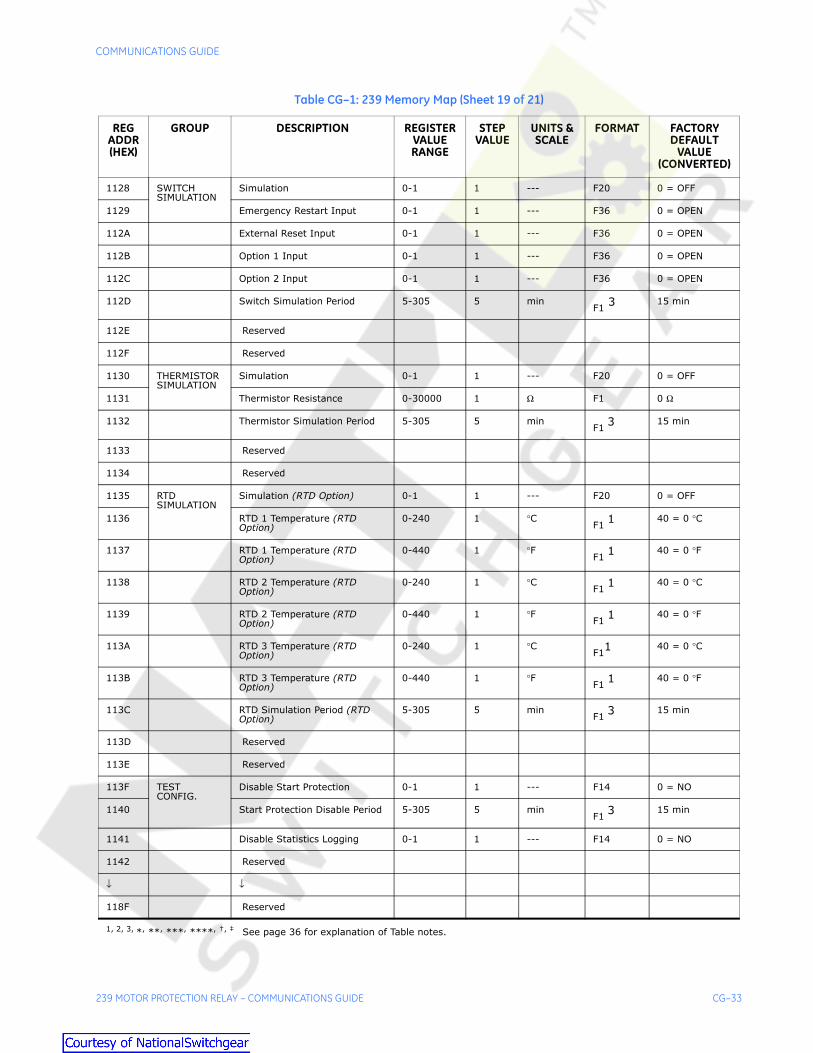
239 MOTOR PROTECTION RELAY – COMMUNICATIONS GUIDE CG–33
1128 SWITCHSIMULATION
Simulation 0-1 1 --- F20 0 = OFF
1129 Emergency Restart Input 0-1 1 --- F36 0 = OPEN
112A External Reset Input 0-1 1 --- F36 0 = OPEN
112B Option 1 Input 0-1 1 --- F36 0 = OPEN
112C Option 2 Input 0-1 1 --- F36 0 = OPEN
112D Switch Simulation Period 5-305 5 minF1
3 15 min
112E Reserved
112F Reserved
1130 THERMISTORSIMULATION
Simulation 0-1 1 --- F20 0 = OFF
1131 Thermistor Resistance 0-30000 1 Ω F1 0 Ω
1132 Thermistor Simulation Period 5-305 5 minF1
3 15 min
1133 Reserved
1134 Reserved
1135 RTDSIMULATION
Simulation (RTD Option) 0-1 1 --- F20 0 = OFF
1136 RTD 1 Temperature (RTD Option)
0-240 1 °CF1
1 40 = 0 °C
1137 RTD 1 Temperature (RTD Option)
0-440 1 °FF1 1
40 = 0 °F
1138 RTD 2 Temperature (RTD Option)
0-240 1 °CF1 1
40 = 0 °C
1139 RTD 2 Temperature (RTD Option)
0-440 1 °FF1 1
40 = 0 °F
113A RTD 3 Temperature (RTD Option)
0-240 1 °CF11 40 = 0 °C
113B RTD 3 Temperature (RTD Option)
0-440 1 °FF1 1
40 = 0 °F
113C RTD Simulation Period (RTD Option)
5-305 5 minF1 3
15 min
113D Reserved
113E Reserved
113F TESTCONFIG.
Disable Start Protection 0-1 1 --- F14 0 = NO
1140 Start Protection Disable Period 5-305 5 minF1
3 15 min
1141 Disable Statistics Logging 0-1 1 --- F14 0 = NO
1142 Reserved
↓ ↓
118F Reserved
Table CG–1: 239 Memory Map (Sheet 19 of 21)
REG ADDR (HEX)
GROUP DESCRIPTION REGISTER VALUE RANGE
STEP VALUE
UNITS & SCALE
FORMAT FACTORY DEFAULT
VALUE (CONVERTED)
1, 2, 3, *, **, ***, ****, †, ‡ See page 36 for explanation of Table notes.

CG–34 239 MOTOR PROTECTION RELAY – COMMUNICATIONS GUIDE
COMMUNICATIONS GUIDE
1190 OPTIONSWITCH 1
Option Switch 1 characters 1 and 2
32-127 1 ASCII F8 "OP"
1191 Option Switch 1 characters 3 and 4
32-127 1 ASCII F8 "TI "
1192 Option Switch 1 characters 5 and 6
32-127 1 ASCII F8 "ON"
1193 Option Switch 1 characters 7 and 8
32-127 1 ASCII F8 " S"
1194 Option Switch 1 characters 9 and 10
32-127 1 ASCII F8 "WI"
1195 Option Switch 1 characters 11 and 12
32-127 1 ASCII F8 "TC"
1196 Option Switch 1 characters 13 and 14
32-127 1 ASCII F8 "H "
1197 Option Switch 1 characters 15 and 16
32-127 1 ASCII F8 "1 "
1198 Option Switch 1 characters 17 and 18
32-127 1 ASCII F8 " "
1199 Option Switch 1 characters 19 and 20
32-127 1 ASCII F8 " "
119A 2nd Phase CT Primary 5-1500 5 A F1 100 A
119B 2nd Motor Full Load Current 1-1500 1 *** F1 100 A
119C 2nd Phase Timed O/L Curve No 1-15 1 --- F1 4
119D 2nd Phase S/C Trip 0-3 1 --- F19 0 = OFF
119E 2nd Phase S/C Pickup 10-110 1 0.1 xCT F1 100 = 10.0 xCT
119F 2nd Phase S/C Delay 0-60000 10 ms F1 ‡ 0 ms
11A0 Reserved
↓ ↓
11AF Reserved
11B0 OPTIONSWITCH 2
Option Switch 2 characters 1 and 2
32-127 1 ASCII F8 "OP"
11B1 Option Switch 2 characters 3 and 4
32-127 1 ASCII F8 "TI "
11B2 Option Switch 2 characters 5 and 6
32-127 1 ASCII F8 "ON"
1193 Option Switch 2 characters 7 and 8
32-127 1 ASCII F8 " S"
11B4 Option Switch 2 characters 9 and 10
32-127 1 ASCII F8 "WI"
11B5 Option Switch 2 characters 11 and 12
32-127 1 ASCII F8 "TC"
Table CG–1: 239 Memory Map (Sheet 20 of 21)
REG ADDR (HEX)
GROUP DESCRIPTION REGISTER VALUE RANGE
STEP VALUE
UNITS & SCALE
FORMAT FACTORY DEFAULT
VALUE (CONVERTED)
1, 2, 3, *, **, ***, ****, †, ‡ See page 36 for explanation of Table notes.

COMMUNICATIONS GUIDE
239 MOTOR PROTECTION RELAY – COMMUNICATIONS GUIDE CG–35
11B6 Option Switch 2 characters 13 and 14
32-127 1 ASCII F8 "H "
11B7 Option Switch 2 characters 15 and 16
32-127 1 ASCII F8 "2 "
11B8 Option Switch 2 characters 17 and 18
32-127 1 ASCII F8 " "
11B9 Option Switch 2 characters 19 and 20
32-127 1 ASCII F8 " "
11BA 3rd Phase CT Primary 5-1500 5 A F1 100 A
11BB 3rd Motor Full Load Current 1-1500 1 *** F1 100 A
11BC 3rd Phase Timed O/L Curve No 1-15 1 --- F1 4
11BD 3rd Phase S/C Trip 0-3 1 --- F19 0 = OFF
11BE 3rd Phase S/C Pickup 10-110 1 0.1 xCT F1 100 = 10.0 xCT
11BF 3rd Phase S/C Delay 0-60000 10 ms F1 ‡ 0 ms
11C0 4th Phase CT Primary 5-1500 5 A F1 100 A
11C1 4th Motor Full Load Current 1-1500 1 *** F1 100 A
11C2 4th Phase Timed O/L Curve No 1-15 1 --- F1 4
11C3 4th Phase S/C Trip 0-3 1 --- F19 0 = OFF
11C4 4th Phase S/C Pickup 10-110 1 0.1 xCT F1 100 = 10.0 xCT
11C5 4th Phase S/C Delay 0-60000 10 ms F1 ‡ 0 ms
11C6 Reserved
11C7 Reserved
11C8 Reserved
11C9 Reserved
11CA Reserved
11CB Reserved
11CC Reserved
11CD Reserved
11CE Reserved
11CF Reserved
↓ ↓
11EF Reserved
Table CG–1: 239 Memory Map (Sheet 21 of 21)
REG ADDR (HEX)
GROUP DESCRIPTION REGISTER VALUE RANGE
STEP VALUE
UNITS & SCALE
FORMAT FACTORY DEFAULT
VALUE (CONVERTED)
1, 2, 3, *, **, ***, ****, †, ‡ See page 36 for explanation of Table notes.

CG–36 239 MOTOR PROTECTION RELAY – COMMUNICATIONS GUIDE
COMMUNICATIONS GUIDE
MEMORY MAP TABLE NOTES
Notes: * = Minimum Setpoint value represents “OFF”
** = Maximum Setpoint value and FFFFH represent “OFF”
*** = 1/Phase Current Scale Factor x A**** = 32767 represents “NO RTD”† = Any valid Actual Values or Setpoints
address‡ = Minimum Setpoint value represents
“INST”1 = Display value = (Modbus Register Value –
40)2 = Display value = 0.0 - 600.0 sec, 10.0 -
6553.5 min3 = Maximum Setpoint value represents
“UNLIMITED”
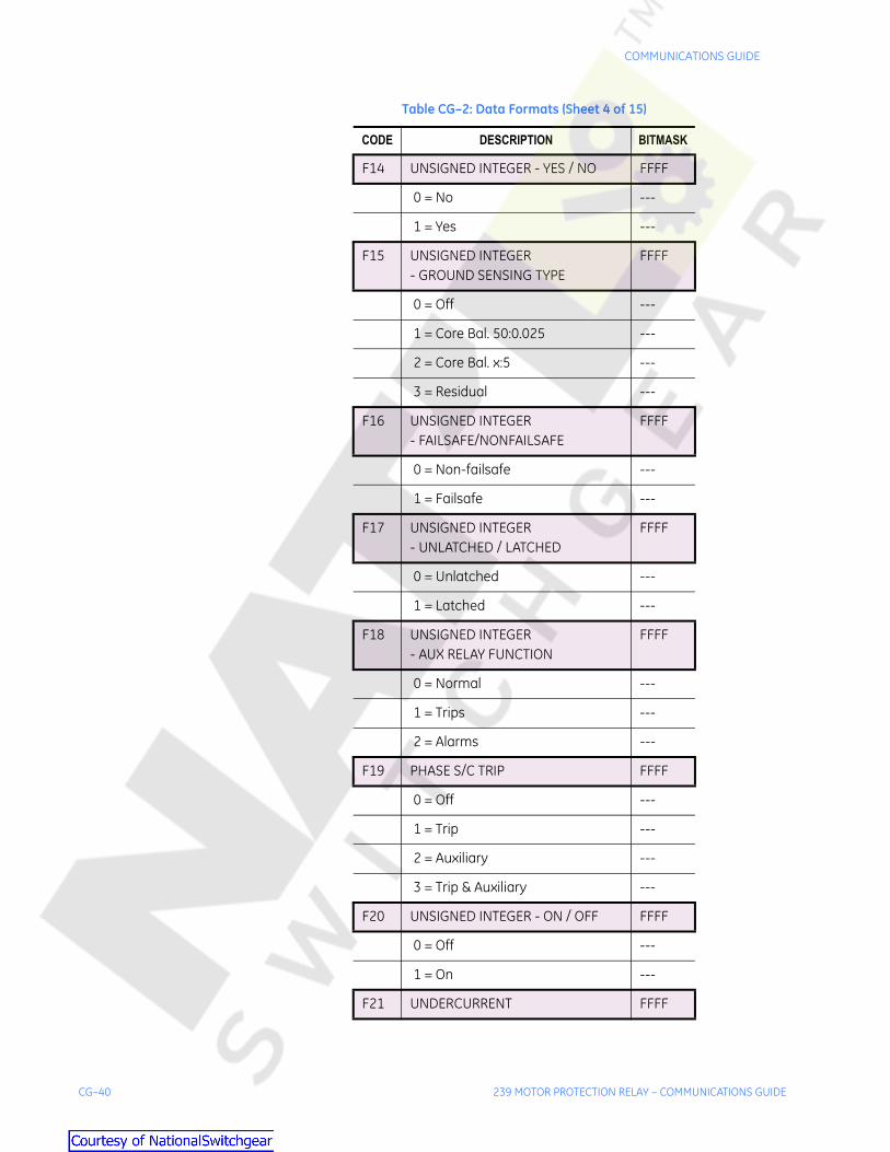
CG.6.3 Memory Map Data Formats
Table CG–2: Data Formats (Sheet 1 of 15)
CODE DESCRIPTION BITMASK
F1 UNSIGNED INTEGER - NUMERICAL DATA
FFFF
F2 SIGNED INTEGER - NUMERICAL DATA
FFFF
F3 HARDWARE VERSION CODE ---
1 = A ---
2 = B ---
. ---
. ---
26 = Z ---
F4 UNSIGNED INTEGER - MOTOR STATUS
FFFF
0 = Starting ---
1 = Stopped ---
2 = Running ---
F5 UNSIGNED INTEGER - CAUSE OF TRIP
FFFF

COMMUNICATIONS GUIDE
239 MOTOR PROTECTION RELAY – COMMUNICATIONS GUIDE CG–37
0 = No Trip ---
1 = Overload ---
2 = Short Circuit ---
3 = Mechanical Jam ---
4 = Unbalance ---
5 = Ground ---
6 = Stator RTD ---
7 = Bearing RTD ---
8 = Thermistor ---
9 = Parameters Not Set ---
10 = Option Switch 1 Trip ---
11 = Option Switch 2 Trip ---
12 = Computer Trip ---
13 = Undercurrent Trip ---
F6 UNSIGNED INTEGER- THERMISTOR STATE
FFFF
0 = Not Connected ---
1 = Cold ---
2 = Hot ---
F7 UNSIGNED INTEGER- CURRENT KEY PRESS
FFFF
0000 = no key ---
FE02 = RESET ---
FE01 = STORE ---
FE08 = SETPOINT ---
FE04 = ACTUAL ---
FD08 = MESSAGE UP ---
FD02 = MESSAGE DOWN ---
FD01 = MESSAGE LEFT ---
FD04 = MESSAGE RIGHT ---
FB01 = VALUE UP ---
Table CG–2: Data Formats (Sheet 2 of 15)
CODE DESCRIPTION BITMASK

CG–38 239 MOTOR PROTECTION RELAY – COMMUNICATIONS GUIDE
COMMUNICATIONS GUIDE
0 = No Trip ---
1 = Overload ---
2 = Short Circuit ---
3 = Mechanical Jam ---
4 = Unbalance ---
5 = Ground ---
6 = Stator RTD ---
7 = Bearing RTD ---
8 = Thermistor ---
9 = Parameters Not Set ---
10 = Option Switch 1 Trip ---
11 = Option Switch 2 Trip ---
12 = Computer Trip ---
13 = Undercurrent Trip ---
F6 UNSIGNED INTEGER- THERMISTOR STATE
FFFF
0 = Not Connected ---
1 = Cold ---
2 = Hot ---
F7 UNSIGNED INTEGER- CURRENT KEY PRESS
FFFF
0000 = no key ---
FE02 = RESET ---
FE01 = STORE ---
FE08 = SETPOINT ---
FE04 = ACTUAL ---
FD08 = MESSAGE UP ---
FD02 = MESSAGE DOWN ---
FD01 = MESSAGE LEFT ---
FD04 = MESSAGE RIGHT ---
FB01 = VALUE UP ---
Table CG–2: Data Formats (Sheet 2 of 15)
CODE DESCRIPTION BITMASK

COMMUNICATIONS GUIDE
239 MOTOR PROTECTION RELAY – COMMUNICATIONS GUIDE CG–39
FB02 = VALUE DOWN ---
F8 TWO ASCII CHARACTERS FFFF
32-127 = ASCII Character 7F00
32-127 = ASCII Character 007F
F9 UNSIGNED INTEGER-TEMP. UNIT(RTD Option)
FFFF
0 = Celsius ---
1 = Fahrenheit ---
F10 ANALOG OUTPUT TYPE (AN Option)
FFFF
0 = Motor Full Load (FLC) ---
1 = Average Phase Amps ---
2 = Thermal Capacity ---
3 = RTD 1 Temperature ---
4 = RTD 2 Temperature ---
5 = RTD 3 Temperature ---
F11 ANALOG OUTPUT RANGE(AN Option)
FFFF
0 = 0-1 mA ---
1 = 0-20 mA ---
2 = 4-20 mA ---
F12 UNSIGNED INTEGER - ENABLE / DISABLE
FFFF
0 = Disable ---
1 = Enable ---
F13 UNSIGNED INTEGER- MODBUS BAUD RATE
FFFF
0 = 1200 ---
1 = 2400 ---
2 = 4800 ---
3 = 9600 ---
4 = 19200 ---
Table CG–2: Data Formats (Sheet 3 of 15)
CODE DESCRIPTION BITMASK
CG–40 239 MOTOR PROTECTION RELAY – COMMUNICATIONS GUIDE
COMMUNICATIONS GUIDE
F14 UNSIGNED INTEGER - YES / NO FFFF
0 = No ---
1 = Yes ---
F15 UNSIGNED INTEGER - GROUND SENSING TYPE
FFFF
0 = Off ---
1 = Core Bal. 50:0.025 ---
2 = Core Bal. x:5 ---
3 = Residual ---
F16 UNSIGNED INTEGER- FAILSAFE/NONFAILSAFE
FFFF
0 = Non-failsafe ---
1 = Failsafe ---
F17 UNSIGNED INTEGER - UNLATCHED / LATCHED
FFFF
0 = Unlatched ---
1 = Latched ---
F18 UNSIGNED INTEGER - AUX RELAY FUNCTION
FFFF
0 = Normal ---
1 = Trips ---
2 = Alarms ---
F19 PHASE S/C TRIP FFFF
0 = Off ---
1 = Trip ---
2 = Auxiliary ---
3 = Trip & Auxiliary ---
F20 UNSIGNED INTEGER - ON / OFF FFFF
0 = Off ---
1 = On ---
F21 UNDERCURRENT FFFF
Table CG–2: Data Formats (Sheet 4 of 15)
CODE DESCRIPTION BITMASK

COMMUNICATIONS GUIDE
239 MOTOR PROTECTION RELAY – COMMUNICATIONS GUIDE CG–41
0 = Off ---
1 = Alarm ---
2 = Auxiliary ---
3 = Trip ---
4 = Alarm & Auxiliary ---
5 = Trip & Auxiliary ---
F22 GROUND ALARM FFFF
0 = Off ---
1 = Momentary ---
2 = Latched ---
F23 THERMISTOR/MECHANICAL JAM FFFF
0 = Off ---
1 = Trip ---
2 = Alarm ---
3 = Auxiliary ---
4 = Trip & Auxiliary ---
F24 RTD APPLICATION(RTD Option) FFFF
0 = Off ---
1 = Stator ---
2 = Bearing ---
F25 RTD TYPE (RTD Option) FFFF
0 = 100 PT ---
1 = 100 NI ---
2 = 120 NI ---
3 = 10 CU ---
F26 OPTION SWITCH FUNCTION FFFF
0 = Off ---
1 = Trip ---
2 = Alarm ---
3 = Auxiliary ---
Table CG–2: Data Formats (Sheet 5 of 15)
CODE DESCRIPTION BITMASK

CG–42 239 MOTOR PROTECTION RELAY – COMMUNICATIONS GUIDE
COMMUNICATIONS GUIDE
4 = Alternate Setpoints ---
5 = Disable Starts ---
F27 COMMAND FFFF
1 = Reset ---
2 = Emergency Restart ---
3 = Computer Trip ---
4 = Auxiliary Relay On ---
5 = Auxiliary Relay Off ---
6 = Display Message ---
7 = Simulate Keypress ---
8 = Upload Mode Entry 2 ---
9 = Upload Mode Entry 1 ---
10 = Factory Setpoints Reload 2 ---
11 = Factory Setpoints Reload 1 ---
12 = Test Relays and LEDs ---
13 = Clear Pre-trip Data ---
14 = Clear Statistics ---
F28 UNSIGNED INTEGER- KEYPRESS SIMULATION
FFFF
49 = '1' = SETPOINT ---
50 = '2' = ACTUAL ---
51 = '3' = RESET ---
52 = '4' = STORE ---
53 = '5' = MESSAGE UP ---
54 = '6' = MESSAGE DOWN ---
55 = '7' = MESSAGE LEFT ---
56 = '8' = MESSAGE RIGHT ---
57 = '9' = VALUE UP ---
97 = 'a' = VALUE DOWN ---
F29 UNSIGNED INTEGER - SYSTEM STATUS
FFFF
Table CG–2: Data Formats (Sheet 6 of 15)
CODE DESCRIPTION BITMASK

COMMUNICATIONS GUIDE
239 MOTOR PROTECTION RELAY – COMMUNICATIONS GUIDE CG–43
0 = Normal ---
1 = Trip ---
2 = Alarm ---
3 = Trip and Alarm ---
4 = Relays & LEDs Test or Simulation On
---
F30 UNSIGNED INTEGER- RELAY/LED TEST DATA
FFFF
0 = Relay/LED Test Off ---
1 = Relay/LED Test On ---
F31 RELAY/LED TEST DATA FFFF
Trip Relay 0001
Alarm Relay 0002
Auxiliary Relay 0004
Service Relay 0008
Trip LED 0010
Alarm LED 0020
Auxiliary LED 0040
Service LED 0080
Pickup LED 0100
Communicate LED 0200
F33 RTD SENSOR FAILURE CAUSE(RTD Option)
FFFF
No Sensor Failure Alarm 0000
RTD 1 0001
RTD 2 0002
RTD 3 0004
F35 PARITY TYPE FFFF
NONE 0000
EVEN 0001
ODD 0002
Table CG–2: Data Formats (Sheet 7 of 15)
CODE DESCRIPTION BITMASK

CG–44 239 MOTOR PROTECTION RELAY – COMMUNICATIONS GUIDE
COMMUNICATIONS GUIDE
F36 SIMULATED SWITCH STATE FFFF
0 = OPEN ---
1 = CLOSED ---
F38 GROUND TRIP FFFF
0 = OFF
1 = TRIP ---
2 = AUXILIARY ---
3 = TRIP & AUXILIARY ---
F39 TIME TO OVERLOAD TRIP UNITS AND SCALE
FFFF
0 = 0.01 x seconds ---
1 = 0.1 x seconds ---
2 = seconds ---
3 = minutes ---
F40 DATE - MONTH/DAY FFFF
Month: 1=January, 2=February, 3=March, etc.
FF00
Day: 1-31 in steps of 1 00FF
F41 DATE - YEAR FFFF
Year: 1995, 1996, 1997, etc. FFFF
F43 OVERLOAD PICKUP INHIBIT ON FFFF
0 = Run ---
1 = Start ---
2 = Start & Run ---
F44 BREAKER FAILURE RELAY ASSIGNMENT
FFFF
0 = Off ---
1 = Alarm ---
2 = Auxiliary ---
3 = Alarm & Auxiliary ---
Table CG–2: Data Formats (Sheet 8 of 15)
CODE DESCRIPTION BITMASK

COMMUNICATIONS GUIDE
239 MOTOR PROTECTION RELAY – COMMUNICATIONS GUIDE CG–45
F45 UNSIGNED LONG INTEGER(NUMERICAL DATA)
FFFFFFFF
F100 SWITCH INPUT STATUS(0=OPEN, 1=CLOSED)
FFFF
Not Used 0001
Not Used 0002
Not Used 0004
Not Used 0008
Not Used 0010
Not Used 0020
Not Used 0040
Not Used 0080
Access 0100
Emergency Restart 0200
External Reset 0400
Option 1 0800
Option 2 1000
Not Used 2000
Not Used 4000
Not Used 8000
F101 LED STATUS FLAGS: (0 = OFF, 1 = ON)
FFFF
Trip 0001
Auxiliary 0002
Pickup 0004
Alarm 0008
Service 0010
Communicate 0020
Not Used 0040
Not Used 0080
Not Used 0100
Table CG–2: Data Formats (Sheet 9 of 15)
CODE DESCRIPTION BITMASK

CG–46 239 MOTOR PROTECTION RELAY – COMMUNICATIONS GUIDE
COMMUNICATIONS GUIDE
Not Used 0200
Not Used 0400
Not Used 0800
Not Used 1000
Not Used 2000
Not Used 4000
Not Used 8000
F102 ALARM STATUS FLAGS: FFFF
Immediate Overload Alarm 0001
Undercurrent Alarm 0002
Unbalance Alarm 0004
Ground Alarm 0008
Thermistor Alarm 0010
Thermistor Open Alarm 0020
Stator RTD Alarm (RTD Option) 0040
Bearing RTD Alarm (RTD Option) 0080
RTD Failure Alarm (RTD Option) 0100
Communication Failure 0200
Internal Fault Alarm 0400
Thermal Capacity Alarm 0800
Option Switch 1 Alarm 1000
Option Switch 2 Alarm 2000
Breaker Failure Alarm 4000
Mechanical Jam Alarm 8000
F103 TRIP FLAGS: FFFF
Ground 0001
Overload 0002
Unbalance 0004
Thermistor 0008
Mechanical Jam 0010
Table CG–2: Data Formats (Sheet 10 of 15)
CODE DESCRIPTION BITMASK

COMMUNICATIONS GUIDE
239 MOTOR PROTECTION RELAY – COMMUNICATIONS GUIDE CG–47
Short Circuit 0020
Stator RTD (RTD Option) 0040
Bearing RTD (RTD Option) 0080
Parameters Not Set 0100
Option Switch 1 0200
Option Switch 2 0400
Computer Command 0800
Undercurrent 1000
Not Used 2000
Not Used 4000
Not Used 8000
F104 GE MULTILIN OPTIONS FFFF
No Options Installed 0000
RTD Option (RTD Option) 0001
Analog Output Option (AN Option) 0002
Harsh Environment Conformal Coating
0004
Not Used 0008
Not Used 0010
Not Used 0020
Not Used 0040
Not Used 0080
Not Used 0100
Not Used 0200
Not Used 0400
Not Used 0800
Not Used 1000
Not Used 2000
Not Used 4000
Not Used 8000
Table CG–2: Data Formats (Sheet 11 of 15)
CODE DESCRIPTION BITMASK

CG–48 239 MOTOR PROTECTION RELAY – COMMUNICATIONS GUIDE
COMMUNICATIONS GUIDE
F105 INTERNAL FAULT ERROR CODE FFFF
ADC Reference Out of Range 0001
HC705 Processor not Responding 0002
Switch Input Circuit Fault 0004
RTD Reference Out of Range (RTD Option)
0008
HC705 MOR Byte Not Programmed
0010
Not Used 0020
Not Used 0040
Not Used 0080
Not Used 0100
Not Used 0200
Not Used 0400
Not Used 0800
Not Used 1000
Not Used 2000
Not Used 4000
Not Used 8000
F106 AUXILIARY STATUS FLAGS: FFFF
Undercurrent 0001
Option Switch 1 0002
Option Switch 2 0004
Alarms 0008
Trips 0010
Short Circuit 0020
Ground 0040
Thermistor 0080
Breaker Failure 0100
Mechanical Jam 0200
Not Used 0400
Table CG–2: Data Formats (Sheet 12 of 15)
CODE DESCRIPTION BITMASK

COMMUNICATIONS GUIDE
239 MOTOR PROTECTION RELAY – COMMUNICATIONS GUIDE CG–49
Not Used 0800
Not Used 1000
Not Used 2000
Not Used 4000
Not Used 8000
F107 RELAYS(0 = DE-ENERGIZED, 1 = ENERGIZED)
FFFF
Trip Relay 0001
Alarm Relay 0002
Auxiliary Relay 0004
Service Relay 0008
Reserved 0010
Not Used 0020
Not Used 0040
Not Used 0080
Not Used 0100
Not Used 0200
Not Used 0400
Not Used 0800
Not Used 1000
Not Used 2000
Not Used 4000
Not Used 8000
F108 LED Attribute Flags(0=flash, 1=solid; when active)
FFFF
Trip 0001
Auxiliary 0002
Pickup 0004
Alarm 0008
Service 0010
Table CG–2: Data Formats (Sheet 13 of 15)
CODE DESCRIPTION BITMASK

CG–50 239 MOTOR PROTECTION RELAY – COMMUNICATIONS GUIDE
COMMUNICATIONS GUIDE
Communicate 0020
Not Used 0040
Not Used 0080
Not Used 0100
Not Used 0200
Not Used 0400
Not Used 0800
Not Used 1000
Not Used 2000
Not Used 4000
Not Used 8000
F109 Names of the Months FFFF
1 = January ---
2 = February ---
3 = March ---
4 = April ---
5 = May ---
6 = June ---
7 = July ---
8 = August ---
9 = September ---
10 = October ---
11 = November ---
12 = December ---
F110 Display Units FFFF
0 = Seconds ---
1 = Minutes ---
F113 Currently Selected Setpoints Group
FFFF
0 = Main Group ---
1 = 2nd Group ---
Table CG–2: Data Formats (Sheet 14 of 15)
CODE DESCRIPTION BITMASK

COMMUNICATIONS GUIDE
239 MOTOR PROTECTION RELAY – COMMUNICATIONS GUIDE CG–51
2 = 3rd Group ---
3 = 4th Group ---
F114 Ground Current Scale Factor FFFF
10 = RESIDUAL or X:5 GROUND SENSING
---
100 = OFF or 50:0.025 GROUND SENSING
---
Table CG–2: Data Formats (Sheet 15 of 15)
CODE DESCRIPTION BITMASK

CG–52 239 MOTOR PROTECTION RELAY – COMMUNICATIONS GUIDE
COMMUNICATIONS GUIDE

INDEX
239 MOTOR PROTECTION RELAY – COMMUNICATIONS GUIDE CG-INDEX–1
Index
Index
A
B
C
COMMUNICATIONSdata format ................................................................................................... CG-2electrical interface ........................................................................................ CG-1error checking ............................................................................................... CG-3error responses ............................................................................................CG-13memory map ................................................................................................CG-14memory map data formats ..........................................................................CG-36memory map information .............................................................................CG-14modbus commands ....................................................................................... CG-6modbus protocol ........................................................................................... CG-1overview ........................................................................................................ CG-1timing ............................................................................................................ CG-5user definable memory area ........................................................................CG-14
D
DATA FRAME FORMAT ................................................................................... CG-2DATA PACKET FORMAT ................................................................................. CG-3DATA RATE ...................................................................................................... CG-2
E
ELECTRICAL INTERFACE ................................................................................ CG-1ERROR CHECKING
communications ............................................................................................ CG-3ERROR RESPONSES
communications ...........................................................................................CG-13
F - L
M
MEMORY MAP ....................................................................................CG-14, CG-15MEMORY MAP DATA FORMATS ...................................................................CG-36MEMORY MAP INFORMATION ......................................................................CG-14MODBUS
commands ..................................................................................................... CG-6function code 05 – execute operation ........................................................... CG-7function code 06 – store single setpoint ....................................................... CG-8function code 07 – read device status .......................................................... CG-8

CG-INDEX–2 239 MOTOR PROTECTION RELAY – COMMUNICATIONS GUIDE
INDEX
function code 08 – loopback test .................................................................. CG-9function code 16 – performing commands .................................................. CG-12function code 16 – store multiple setpoints ................................................. CG-10function codes 03/04 – read setpoints/actual values ................................... CG-6memory map ................................................................................................ CG-15memory map data formats .......................................................................... CG-36protocol ......................................................................................................... CG-1supported functions ...................................................................................... CG-6user definable area ...................................................................................... CG-14
N - S
T
TIMING ............................................................................................................ CG-5
U
USER DEFINABLE MEMORY MAP ................................................................. CG-14
V - Z


![[Cisco] Frame Relay Illustrated Guide](https://img.pdfslide.us/doc/110x75/55cf9001550346703ba236cc/cisco-frame-relay-illustrated-guide.jpg)


![Bosch relay Guide[1].pdf](https://img.pdfslide.us/doc/110x75/55cf9e01550346d033b03ef8/bosch-relay-guide1pdf.jpg)