Embed Size (px)
Citation preview

20m Elevated Vertical Antenna – G8ODE
NOTE:- The antenna wire is cut to the length calculated by the formula ;
1/4 λ = 234 / F MHz (Feet) or 1/4 λ = 75/F MHz (metres).
The counterpoise wires are cut 5-10% longer than the antenna wire, and are used to support the antenna.
Graphics by G8ODE DEC 2010 iss 1.3
Plan View 2m tall wooden
fence
4 radials stapled
to top of fence
Ground
Spike
Elevated
antenna
Copper rod
Aluminium clamping plate
with wing-nut for
counterpoise and SO239
connector
Wires stapled to
fence top
Coax to shack
5m fibreglass fishing pole
8 ferrite chokes on the
50 ohm coax ( RG8)
50cm diam halo capacity
6'0" ( 1.83m)
10'0" ( 2.35m)Old duralumin
surf board mast

n
Tuning the Antenna
It may be necessary to dismount the fishing pole from the aluminium plate several times in order to adjust the length of
the vertical and reposition the halo slightly on the pole
An antenna analyser such as the Autek VA 1 is useful for this task, but with care a transceiver on low power and a good
quality SWR meter will suffice. A cross-needle SWR meter is recommended. Other types with a forward power
calibrate will require re-calibration to full-scale whenever the SWR changes. The wire lengths are calculated using the
formula;
1/ 4 wave = 234/ Frequency ( MHz) feet or 75/F (MHz) metres
14.000 MHz = 16' 8" ( 5.1m approx)
14.350 MHz = 16' 4 “ ( 5.0m approx)
Cut the antenna wire slightly longer than the result given by the formula (+10% approx) and trim the wire for the best
SWR. The four radials wires should be cut to the same length as the antenna wire, but these should not be trimmed
during tuning. The elevated vertical antenna counterpoise wires are intentionally drooped as this increases the input
impedance to around 50 ohms ( see page 4 Theory). The design of the counterpoise system has been dictated by the
restriction in space
The radiator is carefully trimmed 1-2 cm at a time until a low SWR is obtained <1.4:1.
Note that a 4” (10cm) change in antenna length shifts the frequency by 350 KHz.
Picture shows the shorter 20m Elevated Vertical
“fishing pole” antenna alongside the 40m Vertical.
The 20m halo top-hat loading capacitor is obscured by
the branch of the nearby tree.
The 20m vertical is only guyed at the top of the
duralumin ex-sailboard mast using the 4 counterpoise
wires.
The fibreglass pole has no guys and has survived 60km
gusts and three winters.
In contrast the longer 40m vertical requires guys
halfway up the fibreglass fishing pole allowing only the
top half to flex in the gusts.
G8ODE
Graphics by G8ODE DEC 2010 iss 1.3
20m Elevated Vertical Antenna – G8ODE
20m Elevated Vertical Antenna – G8ODE
THEORY
i1 i2
i3
50Ω coax
Effect of the paired radials
.
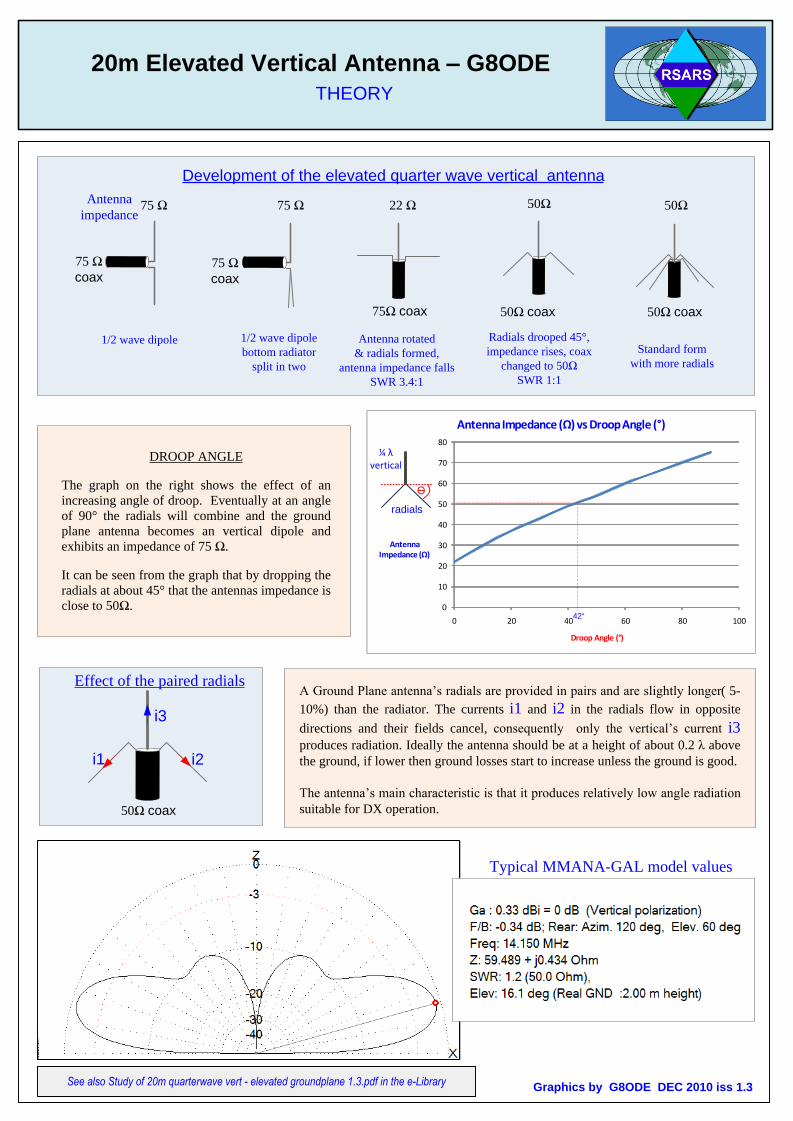
DROOP ANGLE
The graph on the right shows the effect of an
increasing angle of droop. Eventually at an angle
of 90° the radials will combine and the ground
plane antenna becomes an vertical dipole and
exhibits an impedance of 75 Ω.
It can be seen from the graph that by dropping the
radials at about 45° that the antennas impedance is
close to 50Ω. 0
10
20
30
40
50
60
70
80
0 20 40 60 80 100
Antenna Impedance (Ω)
Droop Angle (°)
Antenna Impedance (Ω)vs Droop Angle (°)
Ө
¼ λvertical
radials
A Ground Plane antenna’s radials are provided in pairs and are slightly longer( 5-
10%) than the radiator. The currents i1 and i2 in the radials flow in opposite
directions and their fields cancel, consequently only the vertical’s current i3
produces radiation. Ideally the antenna should be at a height of about 0.2 λ above
the ground, if lower then ground losses start to increase unless the ground is good.
The antenna’s main characteristic is that it produces relatively low angle radiation
suitable for DX operation.
Graphics by G8ODE DEC 2010 iss 1.3
75 Ω
coax75 Ω
coax
22 Ω 75 Ω 75 Ω
50Ω coax
50Ω 50Ω
Development of the elevated quarter wave vertical antenna
1/2 wave dipole 1/2 wave dipole
bottom radiator
split in two
Antenna rotated
& radials formed,
antenna impedance falls
SWR 3.4:1
Radials drooped 45°,
impedance rises, coax
changed to 50Ω
SWR 1:1
Standard form
with more radials
75Ω coax
Antenna
impedance
50Ω coax
Typical MMANA-GAL model values
42°
See also Study of 20m quarterwave vert - elevated groundplane 1.3.pdf in the e-Library

20m Elevated Vertical Antenna – G8ODEMMANA-GAL Model of the Antenna
MMANA-GAL calculated results before, and after, optimizing the vertical wire are displayed below. The SWR graph
shows the antenna is tuned close to 14.15MHz corresponding to the minimum value of SWR (1.38:1). The small Far
Field plot table shows the R +jX values and gain and the vertical field. The three other plots are screen snapshots taken
from the 3D Far Field screen showing the vertical polarisation. In practice, it was not possible to achieve the ideal 42° angle, however, the SWR measured with an Autek VA1 antenna analyser at the feed point is 1.4:1 and closely matches
the MMANA-GAL calculated value.Mario G8ODE
The MMANA-GAL calculations. Line 1 is the first run & line 2
shows the last value recorded after the antenna was optimised
for minimum SWR
Graphics by G8ODE DEC 2010 iss 1.3

n
20m Elevated Vertical Antenna – G8ODE
Unscrew the nylon end cap with a rubber disc off the fishing rod. The rubber disc is discarded and replaced
with a thick brass washer. The washer’s hole is enlarged to be very slightly larger than the diameter of the
PL259 cable end. Carefully position the PL259 connector in the washer ready for soldering. Flow solder
over the top of the washer and into the gap between the washer and connector to firmly secure the PL259
connector. Remove any flux residue and insert the washer & PL259 connector into the end cap. Complete
the modification by firmly screwing on the end cap.
Modification to Attach PL259 to the end of the Fishing Rod
Graphics by G8ODE DEC 2010 iss 1.3