Embed Size (px)
Citation preview

SteppIR 20m Dipole Instruction Manual
Revision 02/22/08
(Patent Pending) Yagi � Dipole � Vertical (Patented)
SteppIR Antennas 2112 116th Ave NE, Suite 2-5 - Bellevue, WA 98004
Tel: 425-453-1910 Fax: 425-462-4415 Tech Support: 425-891-6134
www.steppir.com

SteppIR Antennas - Dipole 2
Abbreviations
EHT Element Housing Tube
EHU Element Housing Unit
EST Element Support Tube (pole)
FCC Flexible Connection Coupler (rubber)
EST
EHU
EHT
FCC
SteppIR Antenna Information Web Sites (as of 4/09/07)
http://steppir.com/ http://groups.yahoo.com/group/steppir/

SteppIR - Why Compromise? The SteppIR antenna was originally conceived to solve the problem of covering the six ham bands (20m, 17m, 15m, 12m, 10m and 6m) on one tower without the performance sacrifices caused by interaction between all of the required antennas. Yagis are available that cover 20 meters through 10 meters by using interlaced elements or traps, but do so at the expense of significant performance reduction in gain and front to back ratios. With the addition of the WARC bands on 17m and 12m, the use of interlaced elements and traps has clearly been an exercise in diminishing returns. Obviously, an antenna that is precisely adjustable in length while in the air would solve the fre-quency problem, and in addition would have vastly improved performance over existing fixed length yagis. The ability to tune the antenna to a specific frequency, without regard for band-width, results in excellent gain and front to back at every frequency. The SteppIR design was made possible by the convergence of determination and high tech materials. The availability of new lightweight glass fiber composites, Teflon blended thermo-plastics, high conductivity copper-beryllium and extremely reliable stepper motors has allowed the SteppIR to be a commercially feasible product. The current and future SteppIR products should produce the most potent single tower antenna systems ever seen in Amateur Radio! We thank you for using our SteppIR antenna for your ham radio endeavors. Warm Regards,
Mike Mertel Michael (Mike) Mertel - K7IR President
SteppIR Antennas - Dipole 3

SteppIR Antennas - Dipole 4
SteppIR Design Currently, most multi-band antennas use traps, log cells or interlaced elements as a means to cover sev-eral frequency bands. All of these methods have one thing in common–they significantly compromise performance. The SteppIR™ antenna system is our answer to the problem. Resonant antennas must be made a specific length to operate optimally on a given frequency. So, instead of trying to “trick” the antenna into thinking it is a different length, or simply adding more elements that may destructively interact, why not just change the antenna length? Optimal perform-ance is then possible on all frequencies with a lightweight, compact antenna. Also, since the SteppIR can control the element lengths, a long boom is not needed to achieve near optimum gain and front to back ratios on 20 - 10 meters. Each antenna element consists of two spools of flat copper-beryllium tape conductor (.54” Wide x .008” Thick) mounted in the element housing unit. The copper-beryllium tape is perforated to allow a stepper motor to drive them simultaneously with sprockets. Stepper motors are well known for their ability to index very accurately, thus giving very precise control of each element length. In addition, the motors are brushless and provide extremely long service life. The copper-beryllium tape is driven out into a hollow fiberglass elements support tube (see below), forming an element of any desired length up to the limit of each specific antenna model (a vertical uses only one side). The fiberglass elements support tubes (poles) are telescoping, lightweight and very du-rable. When fully collapsed, each one measures approximately 48” in length. Depending on the model, their may be additional extensions added to increase the overall element length. The ability to completely retract the copper-beryllium antenna elements, coupled with the collapsible fiberglass poles makes the entire system easy to disassemble and transport. The antenna is connected to a microprocessor-based controller (via 22 gauge conductor cable) that offers numerous functions including dedicated buttons for each ham band, continuous frequency selection from 40m to 6m (depending on the model). There are also 17 ham and 6 non-ham band memories and you can select a 180° direction reversal* or bi-directional* mode and it will adjust in just about 3 seconds (* yagi only). Boom
Element Housing UnitElement Support TubeStepper Drive Motor Copper Beryllium Tape
Copper-Beryllium Tape

SteppIR Antennas - Dipole 5
Abbreviations 2
SteppIR “Why Compromise?” 3
SteppIR Design 4
Table of Contents 5
Connect the Wiring and Secure to Boom 6
Control Cable Schematic 7
Prepare the Telescoping Fiberglass Element Support Tubes (EST) 8
Attach the Fiberglass Element Support Tubes to the Element Housing Units 11
Dipole Installation 12
Dipole Mast Plate Drawing 13
SteppIR Notes 14
6 Meter Passive Element Installation (optional) 14
SteppIR Warranty 15
Topic Page

SteppIR Antennas - Dipole 6
Connect the wiring and secure to boom WARNING : Make sure the 25-pin sub-D connector is not connected to the controller if the 24 volt
power supply is energized and plugged into the controller. There are voltages present on the control cable wires even when the power button on the controller has been pushed to “off”. Shorting the control wires with power on them will destroy the driver chips. Either unplug the 24 volt power supply or disconnect the 25-pin sub-D connector before making any connections or cutting or splicing the cable.
Also, be aware that if you have more than 200’ of control cable you must use our op-tional 33 volt power supply. This will then allow up to 500’ of control cable with no problems.
Be sure to connect the controller case to your station ground using the #8-32 lug on the back of the controller. This is important for RFI immunity as well as lightning protection. If you are in a high lightning area take the appropriate precautions the controller can be damaged by lightning. (it is be-yond the scope of this manual to cover all of the complexities of lightning protection, see some of the ARRL publications that address this) The surest protection is to disconnect the 25-pin sub-D connec-tor and power supply, then move them well away from the controller. The element housing will have an installed 4 pin female plug socket attached to it to connect the con-trol cable and the antenna connector (Figure 1).
Figure 1
Control Cable Connector
Antenna Connector

When the control cable and coax have been connected you can tape the two cables together for the run to your shack. Be sure to leave a proper loop at the mast to allow for the turning of the rotor.
SteppIR Antennas - Dipole 7 BlackRedGreenWhite 1234Shield Solder Drain toConnector CaseMale 25-Pin D-sub.4-pin Weatherproof123412 344-pin pinout viewedfrom the solder side Assemble over cablebefore soldering
BlackRedGreenWhiteControl Cable Schematic
Figure 3
Figure 5

SteppIR Antennas - Dipole 8
Prepare the Telescoping Fiberglass Element Support Tubes (EST) Locate: ● Dark green fiberglass telescoping poles (Figure 7) * ● Two black rubber boots with clamps ● Rolls of black electrical tape ** ● Rolls of black silicone self-curing tape ** ● Your tape measure * Dipole — 2 poles
** The quantity of tape provided will depend
on the number of elements. Large rolls are 20 ft, small rolls are 10 ft.
Note: The steel reinforcing rings on the first two pole sections provides extra strength in potential
high wind conditions. The green fiberglass poles are all assembled in the same manner, and when extended, become element support tubes (ESTs) for the flat strip copper beryllium elements themselves. The copper-beryllium strips are shipped retracted inside their element housing unit (EHU). Repeat the following procedure for each telescoping pole Telescope a pole to full length by pulling each section out firmly in a twisting motion until it is ex-tended as far as possible. Each segment is tapered and should lock securely in place when fully ex-tended. Pole lengths may vary but, when fully extended, each pole must be at least 17 feet 8 inches in length as measured from the butt end of the pole to the tip (Figure 7). Verify the length for each pole before installation or wrapping the joints. If a pole comes up a little short (1/2” to 1”) try collapsing the pole and starting over, this time aggressively “jerk” each sec-tion out instead of twisting. The pole cannot be damaged and you may gain a minimum of 1/2” or more. If you have trouble collapsing the pole try carefully striking one end on a piece of wood or other similar surface placed on the ground.
Figure 7
17’ 8” min
Electrical Tape Silicone Tape
Rubber Boots

Warning: Make sure to remove the black rubber plug from the base section of each of the telescop-
ing element support tubes (poles). This is a shipping plug for handling convenience and will seriously damage the copper-beryllium strips and drive mechanisms if not removed.
Check all four sections of each pole for packing popcorn or any other foreign object that could interfere with the copper tape movement. There are foam plugs glued in the small end of each of the dark green telescoping poles. These plugs allow the poles to breathe preventing the buildup of condensation inside. Do NOT remove, block, cover, plug, cap or in any way inhibit air flow through this foam plug filter.
Note: The telescoping element support tubes will not all be the same length, this is not a problem as
long as they are a minimum of 17’ 8”. They are interchangeable and can be used in any ele-ment position.
Next wrap each joint on the fiberglass poles with the all weather electrical tape, see Figure 9. Each joint should have at least the full width of the tape on both sides of the joint. Use common sense on the amount of tape or you will not have enough of the silicon tape used later to cover the electrical tape. Exception: On joints with reinforcing rings, the tape must continue further so it extends a minimum
of 3/4” beyond the metal ring and onto the fiberglass pole. Apply one complete wrap of electrical tape around the fiberglass tube as you begin, and then work your way across the joint and back using half overlap wraps, so that the entire area is seamlessly cov-ered. Carefully stretch and smooth the tape with your finger as you apply, and especially when you change directions - this will help avoid ripples and have the tape lie as smoothly as possible. At the end of the run, cut the tape with a knife or scissors and press the end onto the pole. Then run your hand over the tape a couple of times to firm up the bonding.
SteppIR Antennas - Dipole 9
Figure 9 Figure 11

Next, you will weatherproof and UV protect each joint with the black self-curing silicone tape see Fig-ure 11. It is important that you pre-cut the silicone tape to the recommended lengths. If you do so, you will have more than enough for each joint. Refer to Figure 13 for proper lengths for each joint. In the event you require more silicone wrap, Home Depot electrical department carries Model HTP-1010 Gardner Bender Silicone Rubber Fusion Tape, UPC code: 032076560102; and Radio Shack and Wall-Mart are authorized retailers for the brand we buy, Tommy Tape. IMPORTANT: Per the manufactures specifications the silicone tape has a shelf life of 12
months before it is used and should be stored in a cool dry environment. Silicone tape will not stick to just any surface. It only bonds to itself. Be sure to remove all the connector protector residue from your hands before handling silicone tape, as that residue will cause the silicone wrap not to adhere to itself in places. Take care to keep the silicone wrap free of dirt or debris. Also, this tape MUST be cut. Do not tear it. Wash your hands before completing the following steps.
Position the black silicone tape about 1/2” to the right of the black electrical tape and wrap one layer, continually stretching the silicone tape a minimum of 100 % its original length, completely around the pole so the tape fully overlaps itself. Then slowly wrap the silicone tape to the left using half overlap wraps, extending about 1/2” beyond the black electrical tape. When you reach the end, wrap one layer completely around the pole so the tape fully overlaps itself just as you did at the beginning of the wrap. If you are stretching the tape correctly you will get about two layers of tape at each joint. As before, carefully stretch and lay the tape down as smooth as possible. The final joint should look like Figure 11. Important : After the silicone tape has been applied, be sure to rub each wrap with your hand
several times to ensure that it is flat and has adhered to itself.
SteppIR Antennas - Dipole 10
Recommended Lengths for Silicone Tape Wrapping
A B C
18 in / 46 cm
11 in / 28 cm
A -
C -16 in / 41 cmB -
Figure 13

Attach the Fiberglass Element Support Tubes to the Element Housing Units The butt ends of the green fiberglass poles may vary slightly in outside diameter. Some of them may have been sanded, while others were not. The colors at the ends will be either natural, or black. The difference in colors has no affect on performance. Do not be concerned if they vary slightly in tight-ness when being installed on the EHUs. This is normal. All poles are tested at the factory prior to shipping, however in the event the pole just won’t fit sanding it is okay. The EHTs on the EHUs have aluminum reinforcing rings attached to provide extra strength in high wind conditions (Figure 15). Locate the six rubber boots and repeat the following procedure for each of the six fiberglass poles. • Place the narrow end of a rubber boot onto the butt end of an EST. Slide it about 6” out onto the
EST (Figure 17).
• Insert the butt end of that EST into one of the EHTs on an EHU, as shown in Figure 19. It is very
important to ensure that the butt end of the EST firmly bottoms out inside the EHT. Make sure the EST is seated all the way into the EHT. Then push the rubber boot firmly onto the EHT until the hose clamp is past the aluminum ring and will clamp down onto the fiberglass EST. The correct mounting position of the rubber boot is shown in Figure 21. It is imperative that the stainless steel hose clamp be located so that the clamp on the outside of the rubber boot on the EHU side of the connection is completely past the aluminum reinforcing ring. This ensures that the hose clamp can grip onto the fiberglass and the ring will prevent the rubber boot from ever coming off.
• Firmly tighten both stainless steel hose clamps, one over the EHT and the other over the EST.
Then test the connection by pulling and twisting it. There should be no slippage at the joints. NOTE: You should re-tighten each clamp a second time (at least 30 minutes after the first time you
tightened them) before raising the antenna to the tower, to be sure that there has been no cold flowing of the PVC material on the rubber boot.
Figure 17 Figure 15 Figure 19 Figure 21
SteppIR Antennas - Dipole 11
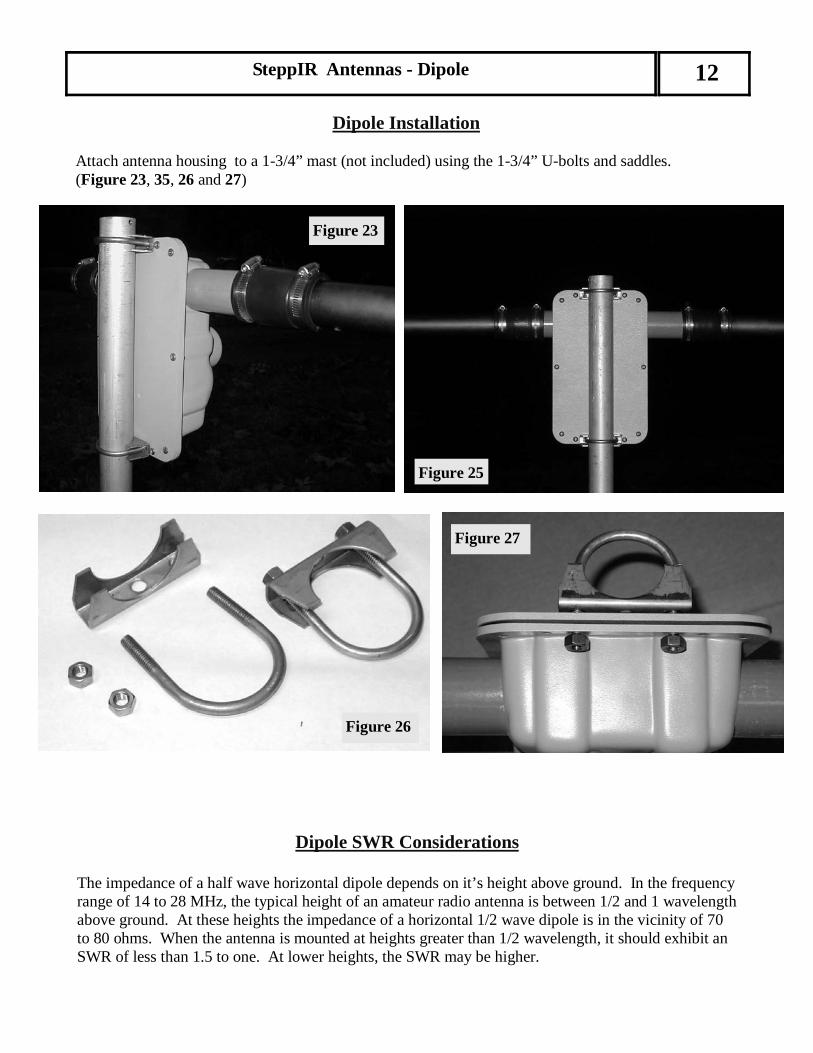
Dipole Installation Attach antenna housing to a 1-3/4” mast (not included) using the 1-3/4” U-bolts and saddles. (Figure 23, 35, 26 and 27)
Dipole SWR Considerations
The impedance of a half wave horizontal dipole depends on it’s height above ground. In the frequency range of 14 to 28 MHz, the typical height of an amateur radio antenna is between 1/2 and 1 wavelength above ground. At these heights the impedance of a horizontal 1/2 wave dipole is in the vicinity of 70 to 80 ohms. When the antenna is mounted at heights greater than 1/2 wavelength, it should exhibit an SWR of less than 1.5 to one. At lower heights, the SWR may be higher.
SteppIR Antennas - Dipole 12
Figure 25
Figure 23
Figure 27
Figure 26

SteppIR
Antennas - D
ipole 13
SteppIR Antennas Inc. Dipole Mast Plate Layout (2” mast) (not supplied - not a production part) Layout provided for customer con-venience and use only
Ø .200 X 12
R 1.000
14.400
2.4503.2003.100
3.200
Ø .430 X 4
6.775
2.565
3.113
2.565 2.738
1.637
1.750
1.226
.370 Ø .344 X 4
C L.380
.390
.380
.390
Material: 3/16” 5053 Aluminum
Figure 29


SteppIR Antennas 15
L i m i t e d W a r r a n t y
These products have a limited warranty against manufacturer's defects in materials or construction for two (2) years from date of sale. Do not modify this product or change physical construction without the written permission of SteppIR Antennas Inc. This limited warranty is automatically void if the following occurs: improper installation, unauthorized modifications, physical abuse or damage from severe weather, beyond the manufacturer's control. Manufacturer's responsibility is strictly limited to repair, or replacement of defective components. The shipping instructions will be issued to the buyer for defective components, and shipping charges will be paid for by the buyer to the manufacturer. The manufacturer assumes no further liability.
www.steppir.com
Yagi � Dipole � Vertical www.steppir.com
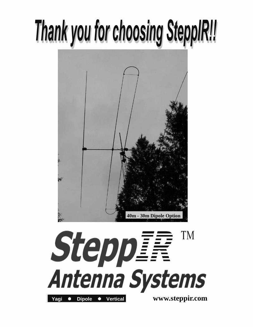
40m - 30m Dipole Option