Embed Size (px)
Citation preview

1
2017 Operator Manual and Parts List
Front Hopper
Please read this manual carefully prior to operating the
machine and store with the machine.
SUMO Serial NO:

2
Redgates
Melbourne
York
YO424RG
Tel: 01759 319900
Fax: 01759 319901
www.sumo1.com
EC DECLARATION OF CONFORMITY (RL 2006/42/EC)
MANUFACTURER: Sumo UK Ltd
ADDRESS: Redgates, Melbourne, York, YO42 4RG.
COUNTRY: United Kingdom
PRODUCT DESCRIPTION: Front Hopper
MODEL: FH
DATE: September 2016
This product conforms to all the essential health and safety requirements of the EC Directive
2006/42/EC
This document is approved by:
NAME: Mr. Shaun Wealleans
POSITION: Technical Director
SIGNATURE:
PLACE: Sumo UK Ltd, Redgates, Melbourne, York, YO42 4RG, United Kingdom.
DATE: March 2015

3
Machine Registration
Warranty claims will NOT be accepted unless this machine registration form is
completed and returned to the address below:
Sumo UK Ltd
Redgates
Melbourne
York
YO42 4RG
Serial number: ……………………………………………………………………………………………………………..
Machine: ………………………………………………………………………………………………………………………
Model: ………………………………………………………………………………………………………………………….
Delivery date: ……………………………………………………………………………………………………………….
I confirm that I have received and read the Operator’s Manual for the machine written
above and I have been instructed by a Sumo dealer or trained operative in the safe and cor-
rect operation of this machine.
……………………………………………………………. ……………………………………………………………….
Signed by dealer or operative Print name
Sumo Dealer
Name: ……………………………………………………
Address: ………………………………………………..
……………………………………………………………….
…………………………………………………...………….
Postcode: ………………………………………………
Tel: ………………………………………………………..
Email: …………………………………………………….
Customer
Name: ……………………………………………………
Address: ………………………………………………..
……………………………………………………………….
……………………………………………………………….
Postcode: ………………………………………………
Tel: ………………………………………………………..
Email: ……………………………………………………
I am aware that a warranty claim can only be carried out if this form is filled in and returned
to Sumo UK Ltd once initial instruction has taken place.
Date: …………………………….
……………………………………………………………… ……………………………………………………………
Receiver’s signature Print name

4
In order to obtain your free pair of Sumo overalls and baseball cap please fill in
this form and send back to us at:
Sumo UK Ltd
Redgates
Melbourne
York
YO42 4RG
Tel: 01759 319900
Fax: 01759319901
Position
Farm Owner
Farm Manager
Farm Worker
Farm Size
0-250ac
251-500ac
501-1000ac
1000+ac
Overall Size Tick where applicable.
Small (38 chest)
Medium (42 chest)
Large (46 chest)
Extra-large (50 chest)
XX Large (54 chest)
XXX Large (58 chest)
Farm type
Arable
Vegetable
Livestock
Mixed

5
Contents Initial set-up operator check list ......................................................................................................... 8
Initial Pipe Set-up guide for coupling up the Sumo DD ...................................................................... 9
Introduction .......................................................................................................................................... 10
Warnings ........................................................................................................................................... 10
Service ................................................................................................................................................... 10
Warranty claims .................................................................................................................................... 11
Safety and Responsibility ...................................................................................................................... 11
Intended use ..................................................................................................................................... 11
Spares .................................................................................................................................................... 12
Qualification of operators ................................................................................................................. 12
Machine operators ........................................................................................................................ 12
Sumo trained operators ................................................................................................................ 12
Children ............................................................................................................................................. 12
Personal Protective Equipment (PPE) ............................................................................................... 13
Fertiliser and dressed seed ............................................................................................................... 13
Road transportation .......................................................................................................................... 13
Operation Safety ................................................................................................................................... 14
General Safety ................................................................................................................................... 14
Commissioning .................................................................................................................................. 14
Avoiding damage to the machine ..................................................................................................... 15
Retrofitting ........................................................................................................................................ 15
Hitching and Unhitching ................................................................................................................... 15
Hydraulic System ............................................................................................................................... 16
Environmental Protection ................................................................................................................. 16
Safety Stickers ................................................................................................................................... 16
1.0 RDS Control System ........................................................................................................................ 18
1.1The Artemis system (Single Motor Kit) ........................................................................................ 18
1.2 Main Functions ............................................................................................................................ 18
1.3 Control Modes and Data Logging ............................................................................................... 19
1.4 Menu Keys ................................................................................................................................... 19
1.5.1 Status Indicators ...................................................................................................................... 21
1.5.2 ‘Main’ Screen ........................................................................................................................... 21

6
1.6 Forward speed display and alarm functions ........................................................................... 22
1.6.1 Display Smoothing ............................................................................................................... 22
1.6.2 Speed alarms on MAIN screen ............................................................................................. 22
1.7 Tramlining status/functions .................................................................................................... 23
1.7.1 Advancing the bout number ................................................................................................. 23
1.7.2 Holding the bout number ..................................................................................................... 23
1.8 Rate Screen ................................................................................................................................. 24
1.8.1 Setting /overriding the target rate ....................................................................................... 25
1.9 Info Screen ................................................................................................................................... 25
1.10 Tramlining ................................................................................................................................. 26
1.11 Metering motor – manual override/Half-Width Shut off (HWSO) drilling ................................ 28
1.12 Product calibration .................................................................................................................... 30
1.13 Set Fan Speed and Hopper Level alarm thresholds ................................................................... 33
1.14 Speed simulation ....................................................................................................................... 34
1.16 GPS Configuration ......................................................................................................................... 37
1.16.1 Port cable configuration......................................................................................................... 37
1.16.2 Head Unit Configuration - Port Settings ................................................................................ 39
1.16.3 Internal Data Card Module .................................................................................................... 40
1.16.4 GPS Receiver ........................................................................................................................... 41
1.16.5 GPS Baud Rate........................................................................................................................ 42
1.16.6 GPS Configuration .................................................................................................................. 42
1.17 Data Logging and Variable Rate Treatment ............................................................................. 43
2.0 Maintenance ................................................................................................................................... 44
2.1 Hydraulics .................................................................................................................................... 44
2.2 Greasing ...................................................................................................................................... 44
2.3 Winter storage ............................................................................................................................ 44
3.0 Hydraulic Systems ........................................................................................................................... 45
3.1 Fan Return Pressure .................................................................................................................... 45
3.2 Fan Motor system ....................................................................................................................... 45
4.0 Operation & Adjustment ................................................................................................................. 46
4.1 Fan adjustment ........................................................................................................................... 46
4.2 Finger Switch ............................................................................................................................... 46
4.3 Front Hopper Overview .............................................................................................................. 46
4.4 Hopper lids .................................................................................................................................. 48

7
4.5 Calibration Procedure ................................................................................................................. 50
4.6 Front Hopper Settings ................................................................................................................. 52
4.7 Orga Metering overview ............................................................................................................. 53
4.8 Orga Metering explained ............................................................................................................ 54
5.0 Parts Assembly overview ................................................................................................................ 55

8
Initial set-up operator check list
It is the owner / drill operator’s responsibility to set up the drill for:
1. Sowing depth according to conditions in each soil type and pre
worked condition
2. Tramline bout number to suit tramlines
3. Tramline track width
4. Marker width setting to allow matching of bouts (3-6m)
5. Operation of half width shut off (standard on 6m and above
via RDS Unit)
6. Folding the machine in and out of work without damage
7. Correct calibration procedure
It is also the owner / operator’s responsibility to check the operation of the
various functions of the machine between each hopper fill, or at least once
every hour to check the machine is operating correctly. A good practice is to
park on the headland with coulters just above the ground, then with the fan
running press the calibration button for a few seconds. This normally will leave
a small pile of seed on the ground beneath each coulter and is a good indica-
tion the drill is working properly. If after this test a number coulters has no
seed beneath them that is a clear indication there may be a blockage within
the pipes.
9
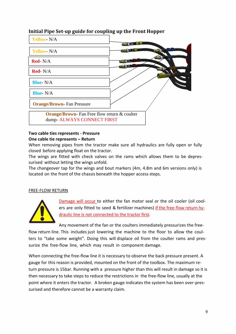
Initial Pipe Set-up guide for coupling up the Front Hopper
Two cable ties represents - Pressure One cable tie represents – Return When removing pipes from the tractor make sure all hydraulics are fully open or fully closed before applying float on the tractor. The wings are fitted with check valves on the rams which allows them to be depres-surised without letting the wings unfold. The changeover tap for the wings and bout markers (4m, 4.8m and 6m versions only) is located on the front of the chassis beneath the hopper access steps.
FREE-FLOW RETURN
Damage will occur to either the fan motor seal or the oil cooler (oil cool-
ers are only fitted to seed & fertilizer machines) if the free-flow return hy-
draulic line is not connected to the tractor first.
Any movement of the fan or the coulters immediately pressurizes the free-
flow return line. This includes just lowering the machine to the floor to allow the coul-
ters to “take some weight”. Doing this will displace oil from the coulter rams and pres-
surize the free-flow line, which may result in component damage.
When connecting the free-flow line it is necessary to observe the back pressure present. A
gauge for this reason is provided, mounted on the front of the toolbox. The maximum re-
turn pressure is 15bar. Running with a pressure higher than this will result in damage so it is
then necessary to take steps to reduce the restrictions in the free-flow line, usually at the
point where it enters the tractor. A broken gauge indicates the system has been over-pres-
surised and therefore cannot be a warranty claim.
Yellow- N/A
Blue- N/A
Orange/Brown- Fan Free flow return & coulter
dump- ALWAYS CONNECT FIRST
Yellow- N/A
Red- N/A
Red- N/A
Orange/Brown- Fan Pressure
Blue- N/A

10
Introduction
Prior to operating the machine, these instructions must be read and complied with. This will
reduce the chance of injury, reduce the chance of machine misuse which could result in failure
of parts and significantly reduce the service life of the machine.
Sumo will not accept liability for any injuries or damage caused from failing to comply with
the instructions within this manual.
The instructions within this manual will enable the operator to operate the machine in a safe
manner and reduce risk to themselves and persons around the machine while it is in opera-
tion.
As well as reading the instructions of operation contained within this manual, a trained tech-
nician or dealer should also instruct you on the correct and safe use of the machine and
maintenance of the machine to ensure a long service life.
By signing the document contained at the front of this manual you are accepting the receipt
of this manual. The warranty starts on the day of delivery of the machine.
The illustrations within this manual may be subject to change and may differ from the ma-
chine you have received.
Warnings
Within these instructions are warnings of safety to protect the health of the user and the
persons surrounding the machine during its operation.
Please read and ensure that these warnings are complied with.
The designations “left”, “right”, “front” and “rear” refer to the direction of travel, as seen in
the direction of travel, as the operator is sat in the driving seat looking forward.
Service
Sumo endeavour to ensure that the machine leaves the factory in perfect working order, if
this is not the case then please let us know as soon as possible.
If you encounter any issues with your machine please contact us or your Sumo dealer, and we
will work to resolve the issue as quickly as possible.
To allow us to process the problem quickly we will need the following information:
- Customer name and address - Sumo dealer name - Machine model - Serial number

11
- Area covered by machine - Type of problem
Warranty claims
Any warranty claims must be submitted through your local Sumo dealer.
If damage to the machine has been caused by external influences then the warranty claim
cannot be honoured. Influences such as:
- Excessive wear of wearing parts
- Missing wearing parts
- Excessive operating speeds
- Excessive transport speeds
- Incorrect set up of machine (hydraulic connections, non-even depth adjustment)
- Failing to comply with safety and operating instructions
- Neglect of maintenance of the machine.
Safety and Responsibility
The following warnings and safety instructions apply to all sections of these operating instruc-
tions.
The machine has been designed and manufactured to meet all of the relevant safety regula-
tions. These regulations along with the instructions provided within this manual will ensure
that risk of injury to yourself or others is minimised.
Please read ALL of these safety instructions prior to the first use of the machine to prevent
safety issues or potential machine damage to the machine through incorrect use.
Intended use
Any use outside of the intended use of the machine can lead to injury or persons operating
or within the area of the machine during operation and can also lead to invalidating the war-
ranty. The machine is intended to be used for normal soil cultivation in agricultural practices.
Any faults with the machine should be rectified prior to use of the machine. Faults can cause
safety issues and can also cause the machine to work in an unsatisfactory manner.
Only qualified persons may operate this machine, they must be familiar with the machine and
familiar with the dangers of the machine.

12
Spares The machine has been designed to take Sumo manufactured spares; non-genuine parts may
damage the machine as they are untested and not recommended for use with the Sumo ma-
chine. Sumo will not honour warranty claims if deemed to be caused by the use of non-gen-
uine parts or accessories.
Safety stickers should always be replaced along with the components they are attached to;
this will ensure the safety of the machine is not compromised.
Qualification of operators
Use of the machine by untrained operators can lead to injury or even death. To prevent acci-
dents occurring ensure that operators have been trained by a Sumo dealer or technician. The
following requirements must be met:
- Personnel must be of statutory minimum age in the country of operation.
- Ensure only authorised persons operate or work on the maintenance of the machine.
- The person has read and understood these instructions in full.
- The person is fully competent in operating the machine towing the equipment.
- Local traffic laws are abided by
- A person being instructed on the use of the machine must be done so under the in-
struction of a trained individual.
The owner of the machine must ensure that these requirements are met and the area of re-
sponsibility is met, train any persons intending on using the machine to ensure they are up to
the required standards and ensure that they have read and understood this manual.
Machine operators
These persons have been trained by the owner or dealer to use and set up the machine in the
field, transport the machine on the road, maintain the machine and troubleshoot errors with
the machine.
Sumo trained operators
Higher training by Sumo is required for the following operations; loading for truck transpor-
tation, commissioning of new machines, advanced troubleshooting and repair.
Any repair work to structural components of the machine must be carried out by Sumo or a
workshop approved by Sumo, otherwise the warranty will be compromised.
Children
Young persons are less able to react to danger and are unlikely to have enough experience to
react to situations so as such should be kept clear of the operating zone of the machine. Chil-
dren should NOT be left in the tractor even when the machine has been shut down as hydrau-
lics can still be operated if they are a mechanical spool. The minimum age of children riding
on agricultural equipment locally in the country of operation must be adhered to.

13
Personal Protective Equipment (PPE)
To protect the user and persons surrounding the machine during operation suitable PPE must
be worn.
Tight fitting clothes or overalls should be worn to ensure no loose clothing is able to get caught
in the machine while it is in operation, this includes long hair, which should be tied up or
placed in a hair net.
Suitable footwear should be worn, steel toe capped shoes/boots should be worn to protect
when components are being lowered to the floor.
Eye protection such as safety glasses or goggles must be worn during the changing of wearing
components as these may be under pressure and can release suddenly, and when working
with hydraulic components as the pressure may not have been released properly and could
release suddenly.
Respiration equipment should be used when working on an area of the machine that has been
in contact with seed dressing or fertiliser as there could be deposits of dust that can be harm-
ful, please refer to seed or fertiliser manufacturers labels for further information on this PPE
requirement.
Jewellery such as rings, bracelets and watches should not be worn while operating this ma-
chine as it has the ability to get caught and cause further injury to the operator.
Hand protection should be worn during the attachment of the machine to a tractor as hy-
draulic oil can cause injury if it is under pressure as it can pierce the skin and can cause serious
health problems if it enters the blood stream.
Fertiliser and dressed seed
Inappropriate handling of fertiliser and dressed seed can cause poisoning or even death.
Follow the information given in the safety data sheet of the manufacturer. If necessary ask
the dealer for the corresponding safety data sheet.
Determine and provide the personal protective clothing as specified by the manufacturer.
Road transportation
When the machine is being transported on the road the local road regulations must be ad-
hered to, regulations such as transport width and height. The route planned should also be
considered to ensure that the machine will fit under low bridges and between narrow gaps.
The way in which the Front Hopper is mounted means the machine increases its total vehicle
length at the front. This may cause difficulty with visibility at junctions and may create blind

14
spots when travelling on the road. Ensure that a factory of safety is given for any manoeuvre
ring in close proximity to people, vehicles or property.
Operation Safety
This manual contains basic advice, which should be observed during setting-up, operation and
maintenance. Therefore, this operating manual must be read by the personnel concerned
prior to starting up and using the machine and be accessible at all times.
If safety instructions are not complied with, then this can lead to the risk of injury to yourself
and others as well as damage to the environment or the machine. Non-compliance to the
safety instructions can also lead to any warranty claims becoming invalid.
General Safety
To avoid serious injury please ensure that the tractor keys are removed before making any
adjustments and maintenance.
Warning signs and other notices on the machine provide important information for the safe
operation. Observing them will serve your safety. Before commencing work, make yourself
familiar with all the equipment and controls as well as their functions. The user should wear
close-fitting clothing. Keep the machine and in particular the bearings clean to avoid risk of
fire.
Check around the machine before moving off or starting up (watch out for children!). Make
sure you have adequate all-round visibility. Always match your speed to the local conditions.
Avoid sudden turning manoeuvres when driving uphill or downhill or when travelling across
a slope. Observe the respective regulations when using public roads. Take into account the
length, the wide overhang, the ground clearance height and the sideways force acting on
the machine when turning or negotiating curves.
Commissioning
Before operation of the Sumo Front Hopper, a full commissioning should take place to avoid
the potential for severe or even fatal accidents. Whilst the Sumo FH undergoes a thorough
inspection before leaving the factory, it cannot be guaranteed that it is safe to use for imme-
diate operation. This could be due to a number of factors including tampering or the transport
environment it has been delivered in. It is imperative that full instruction should be under-
taken by an authorised SUMO dealer or by an appropriate SUMO UK technician, on initial
operation. It is policy that a machine should be registered for use by the end user on delivery
of the machine by Sumo UK or any authorised SUMO dealer. Any initial operation prior to an
official commissioning of the machine that leads to damage of the machinery, or the seri-
ous/fatal injury to personnel/third party claimants will not be the responsibility of SUMO UK.
It is highly recommended that prior to initial/daily use that nuts and bolts be checked and
tightened appropriately on vital components to avoid unnecessary damage and or injury.

15
Please ensure that on initial drill use that it is recalibrated 3 times consecutively after the
1st hour, and the process repeated on the 5th hour.
Avoiding damage to the machine
Avoiding unnecessary damage can both prolong the life of the machine and ensure that the
machine can be operated safely throughout its life. Damage to the machine can result in se-
rious or fatal injury to operators and third parties. Care should be taken in identifying dam-
aged parts and appropriately replacing the damaged items with Sumo genuine parts. Unnec-
essary damage can be avoided if the machine is regularly serviced and maintained within
SUMO guidelines. Items that should be inspected daily as a good safety practice are:
Hydraulic System
Brakes
Hitch System
Lighting
Safety Mechanisms
If a particular component is showing signs of damage that poses a risk to operator and/or
third party safety, operation must either not commence or cease until the fault is assessed
and rectified by a competent/qualified person(s).
Retrofitting
Structural changes and extensions can adversely affect the functionality and the operational
safety of the machine. This can lead to severe or even fatal physical injuries.
Do not make any structural changes or ex- tensions which have not been approved
by SUMO UK.
Structural changes and extensions must only be made in an authorised workshop or
by an operator who has been instructed by SUMO UK.
Comply with country specific instructions fr weights, weight distribution and dimen-
sions.
For retrofits influencing the weight or weight distribution one must check and comply with
the regulations concerning towing facilities, support and axle loads.
Hitching and Unhitching
Faulty hitching up of the machine to the tractor causes dangers, which could result in severe
accidents. Hitching and unhitching of the machine should only take place on a secure and
level surface with chocks placed under the machine transport wheels to prevent machine
rolling away.
Never allow persons to stand between the tractor and the SUMO machine whilst the tractor
is manoeuvring into position. Once the tractor is in position and secured against rolling away

16
by means of parking brake and/or wheel chocks, can the operator/third party secure the ma-
chine to the tractor.
Hydraulic System
The hydraulic system is under high pressure. Hydraulic oil escaping under pressure can pene-
trate the skin and cause serious injuries. In the event of injury, consult a doctor immediately.
The machine's hydraulic system has several functions, which can cause injury to persons or
damage to the machine, if operated incorrectly.
Do not connect hydraulic hoses to the tractor, before both hydraulic systems on ma-
chine and tractor are de-pressurised.
The hydraulic system is under high pressure. Check all lines, hoses and screwed con-
nections regularly for leaks and any visible external damage!
Use only appropriate means when searching for leaks. Repair any damage immedi-
ately! Oil sprays can cause injuries and fire!
Power sockets and connectors on the hydraulic connections should be marked in order
to exclude operating errors.
In the case of injury, contact a doctor immediately!
Secure and lock the control unit on the tractor, if not in use!
Environmental Protection
Operating fluids and such as hydraulic oil and lubricants are damaging to the environment.
Special care should be taken to ensure that operating fluids are not leaking to ensure safe
operation of the machine and damage to the environment. When servicing of the machine it
is important that the disposal of used operating fluids is done responsibly.
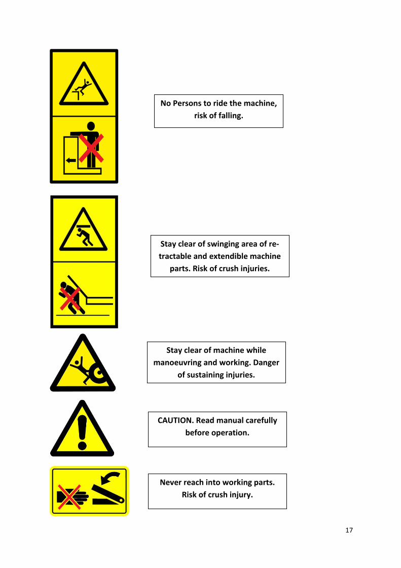
Safety Stickers
Safety stickers on the machine warn of dangerous points and are an important part of
the safety equipment of the machine. Missing safety stickers increase the risk of severe or
even fatal physical injuries.
17
Stay clear of swinging area of re-
tractable and extendible machine
parts. Risk of crush injuries.
Stay clear of machine while
manoeuvring and working. Danger
of sustaining injuries.
CAUTION. Read manual carefully
before operation.
Never reach into working parts.
Risk of crush injury.
No Persons to ride the machine,
risk of falling.
18
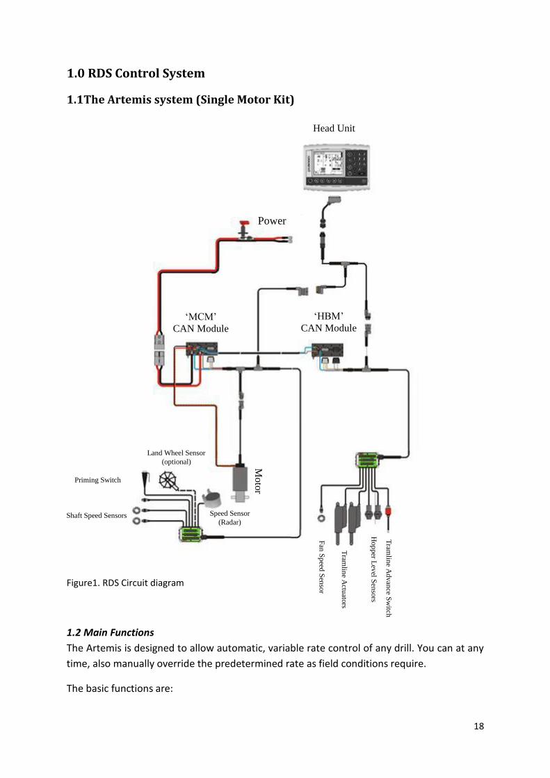
1.0 RDS Control System
1.1The Artemis system (Single Motor Kit)
Figure1. RDS Circuit diagram
1.2 Main Functions
The Artemis is designed to allow automatic, variable rate control of any drill. You can at any
time, also manually override the predetermined rate as field conditions require.
The basic functions are:
Power
‘MCM’
CAN Module
Head Unit
‘HBM’
CAN Module
Mo
tor
Tram
line A
dvan
ce Sw
itch
Hop
per L
evel S
enso
rs
Tram
line A
ctuato
rs
Fan
Sp
eed S
enso
r
Shaft Speed Sensors
Priming Switch
Land Wheel Sensor
(optional)
Speed Sensor
(Radar)

19
Variable Rate Control
Tramline Control
Forward Speed Alarms
Hopper Level alarm
Fan Speed & alarm
Information totals
The instrument has a special software routine that makes calibration of the metering unit(s)
very easy. In the calibration mode each metering unit is controlled via a ‘priming switch’ to
dispense the product.
During normal operation the control system is started and stopped automatically via a mag-
netic sensor as the drill is put into and taken out of work. Depending on the particular instal-
lation, this sensor is triggered either by the operation of the lift/lower action or by the mark-
ers.
1.3 Control Modes and Data Logging
1.3.1 Automatic Control Mode
The application rate is automatically regulated as forward speed varies, to ensure that the
actual application rate constantly matches a preset target rate. The application rate can
be manually nudged up and down from the target rate as required.
Field data ("job summaries") can be logged and are stored in the instrument memory. Up
to 75 summaries can be stored. With a GPS receiver and SD data card, as well as
creating a job summary, you can also log the vehicle route and application data to a
"dynamic log" file on the SD card. The job summary data is also appended to this file.
1.3.2 VRT (Variable-rate treatment) Control Mode
This enables the system to be controlled via treatment instructions prepared using Precision
Farming software in conjunction with DGPS position data. To enable fully automatic variable-
rate treatment for Precision Farming applications, the PS 8000i requires a suitable DGPS re-
ceiver and a formatted SD data card to implement treatment plans generated in the Precision
Farming software.
A work record file is automatically created on the card to log data confirming the actual treat-
ment. The job summary data is also appended to this file, which can be viewed in the Precision
Farming software
1.4 Menu Keys
All instrument functions are accessed by nine menu keys adjacent to the LCD display.

20
Figure2. Main function keys
The four menu keys to the right of the screen access the primary screen pages (those
viewed during normal operation). There are three primary screens MAIN, RATE and INFO
for normal operating functions, and a SETUP screen for calibration functions.
The five sub-menu keys below the screen control the various display functions and settings
for each of the primary screen pages. Text or icons are displayed adjacent to the sub-menu
keys to denote their function.
Enter
Backspace
SD card reader Sub-menu “soft keys”
Power on/off

21
1.5 RDS Control Unit Operation 1.5.1 Status Indicators All the operating screens have a status bar at the top of screen displaying the time as well as a number of different icons. These icons indicate the following:
Figure3. Status symbols NOTE: The Data Card and GPS icons are only displayed when these functions are enabled via the SETUP menu.
1.5.2 ‘Main’ Screen
The instrument will always default to the MAIN screen on startup. The MAIN screen is di-
vided into 5 sections displaying the following functions,
Figure 4. MAIN screen (single product / single metering) NOTE: The Metering motor status part of the display will appear differently depending on the drill configuration
Data Card DGPS Signal
Inserted No signal
Not inserted Signal - no differential.
Signal – full differentia
In Work
Out of Work
Metering Motor Status
(Section 2.7)
Tramlining status
(Section 2.5)
Fan Speed
(Section 2.9)
Forward Speed
(Section 2.2.1)
Current Application
Rate
(Section 2.3)
Tramline Manual
Advance
Stop Tramline Automatic
Advance
(Manual Override)
Metering On-Off
‘Pre-start’ function

22
Figure 5. MAIN screen (dual product / single metering)
Figure 6. MAIN screen (single product / dual metering)
1.6 Forward speed display and alarm functions
1.6.1 Display Smoothing
Except for sudden changes in speed, the forward speed displayed at any moment will be the
average speed calculated over 3 seconds.
1.6.2 Speed alarms on MAIN screen
The instrument is programmed with low and high forward speed alarms.
If the drill is in work and
the speed is less than
0.5 km/h then this sec-
tion of the MAIN display
will flash the following
If the drill is in work and
the speed is above the
maximum that propor-
tional control can
achieve (indicated on
the RATE screen), then
this section of the MAIN
Display as Fig.4 except as shown
Display as Fig.4 except as shown

23
When setting a new target rate on the RATE screen, the instrument re-calculates and displays the
maximum forward speed at which that rate can be maintained (Fig.7). It is calculated from the
rate set, drill working width, current calibration factor, gearbox ratio and maximum motor speed.
Figure 7. Maximum speed reminder
Simply press the key to return to the RATE screen.
NOTE: If the speed is too low, the operator must open the metering unit and re-calibrate to increase the calibration factor (ref. the‘Calibration’ manual).
1.7 Tramlining status/functions
The MAIN screen shows the current status of tramlining.
1.7.1 Advancing the bout number
On starting up the instrument the tramline sequence always starts at ‘1’.
If necessary, press the key to select the correct current bout number, e.g. if entering work on
a bout other than bout 1 of the tramline sequence.
1.7.2 Holding the bout number
Press the key to hold the current bout number (e.g. to prevent the bout no. advancing if it is
necessary to take the drill out of work, or depending on the drill setup - lift a marker, to ne-
gotiate a field feature).
The icon indicates that the bout no. is held. Press the key to resume normal
bout advance.
NOTE: The tramlining sequence is set up via the SETUP page.
Tramline Rhythm
Output status ( = ON)
Current Bout
Target No of Bouts
Symmetrical Asymmetrical Left Asymmetrical Right

24
1.8 Rate Screen
This screen allows the drilling rate to be adjusted. Either kg/ha or seeds/m2 units can be set via the
SETUP menu.
Figure 8. RATE screen - single product
Figure 9. RATE screen - dual product
NOTE: The maximum forward speed shown is the lowest for the 2 products.
Current Drilling Rate
(Section 2.2.1) Target Rate
(Section 2.2.1) % off target
(Section 2.2.1) Rate step size
(Section 2.2.1)
Maximum forward speed at
which the current drilling rate
can be maintained.
Reset to target
(Section 2.2.1)
Target rate manual override by % steps.
(% step size set in SETUP menu)

25
1.8.1 Setting /overriding the target rate
To set the target rate, simply enter the value and press the ENTER key to confirm.
To set the target rate or manually adjust the rate for either product, first press the ENTER
key to select SEED or FERT.
The application rate on the MAIN screen is the same as that shown on the RATE screen above. If
however on the rate screen, the current rate is manually adjusted above or below the target rate, then
this number will flash (on for 1 second, off for 0.5 second).
When operating from a treatment plan, then this number should only flash if the instructed rate has
been changed using the ‘+’ or ‘–‘ percentage buttons on the rate screen.
To override the target rate, use the keys. The % step is configured from the SETUP
menu.
To return to the target rate, press the key.
Both products are reset to their respective target rates
1.9 Info Screen
Area total
Seed total
Fertiliser total
Select Part Total /
Normal Total display
Reset selected Select Grand total display
(No function)
There is a ‘PART’ and a ‘NORMAL’ total for each product
Figure 10. Info screen graphics and functions
(No function)

26
1.10 Tramlining
To set the desired tramline rhythm, select the SETUP screen and press the key.
Figure 11. Tramline set up screen
The target no. of bouts can be selected up to 10, with, symmetrical, asymmetrical left or asymmetrical
right rhythm selectable.
Symmetrical Asymmetrical left Asymmetrical right
The instrument displays the drill/sprayer width combination for the selected target no. of bouts.
Beyond 10 bouts, a number of special asymmetric rhythms can be selected to suit the following drill/sprayer width combinations. ‘8-pass’ 4m drill/10.7m sprayer, 4.5m drill/12m sprayer ‘10-pass’ 4m drill/10m sprayer, 6m drill/15m sprayer ’ ‘10-pass’ 4m drill/13.3m sprayer, 6m drill/20m sprayer ’ ‘14-pass’ 3m drill/14 sprayer, 4m drill/18.7m sprayer
‘16-pass‘ 4m drill/21.3m sprayer, 4.5m drill/24m sprayer
‘18-pass‘ 4m drill/18m sprayer
‘22-pass‘ 4m drill/29.3m sprayer
The tramline sequences (‘L’ – Left, ‘R’ – Right) are as follows:
Select rhythm
Increase/decrease
target no. of bouts
Sprayer width is
based on the drill
width, target no.
of

27
Bout 8-pass 10-pass 10-pass 14-pass 16-pass 18-pass 22-pass
1
2 R R L
3 L R L
4 L L L
5 L R
6 R
7 R L R R
8 R L
9 R L L
10
11 R
12 L R R
13
14 R
15
16 L
17
18
19 L
20
21
22
Figure 12. Table showing the tramline sequences (‘L’ – Left, ‘R’ – Right)
28
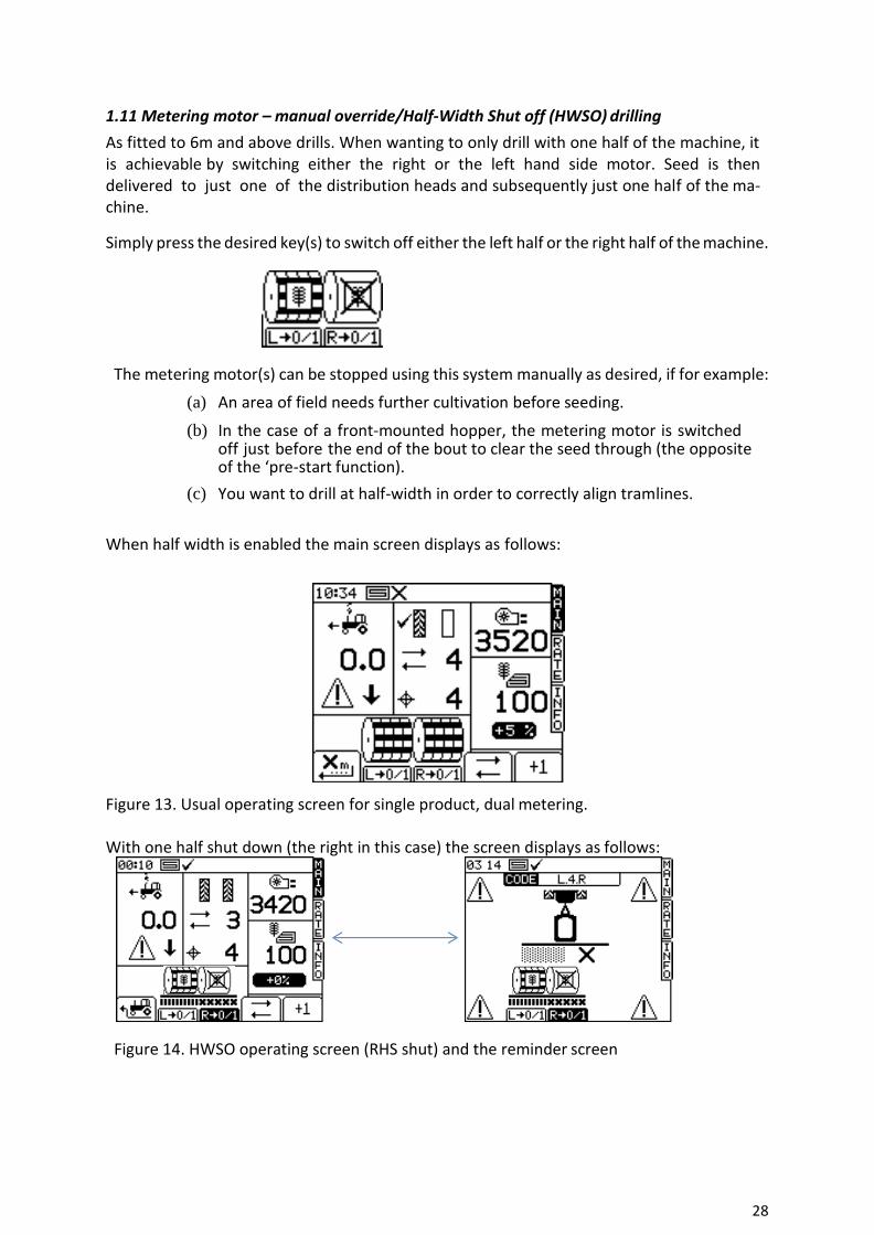
1.11 Metering motor – manual override/Half-Width Shut off (HWSO) drilling
As fitted to 6m and above drills. When wanting to only drill with one half of the machine, it is achievable by switching either the right or the left hand side motor. Seed is then delivered to just one of the distribution heads and subsequently just one half of the ma-chine.
Simply press the desired key(s) to switch off either the left half or the right half of the machine.
The metering motor(s) can be stopped using this system manually as desired, if for example:
(a) An area of field needs further cultivation before seeding.
(b) In the case of a front-mounted hopper, the metering motor is switched off just before the end of the bout to clear the seed through (the opposite of the ‘pre-start function).
(c) You want to drill at half-width in order to correctly align tramlines.
When half width is enabled the main screen displays as follows:
Figure 13. Usual operating screen for single product, dual metering. With one half shut down (the right in this case) the screen displays as follows:
Figure 14. HWSO operating screen (RHS shut) and the reminder screen
29
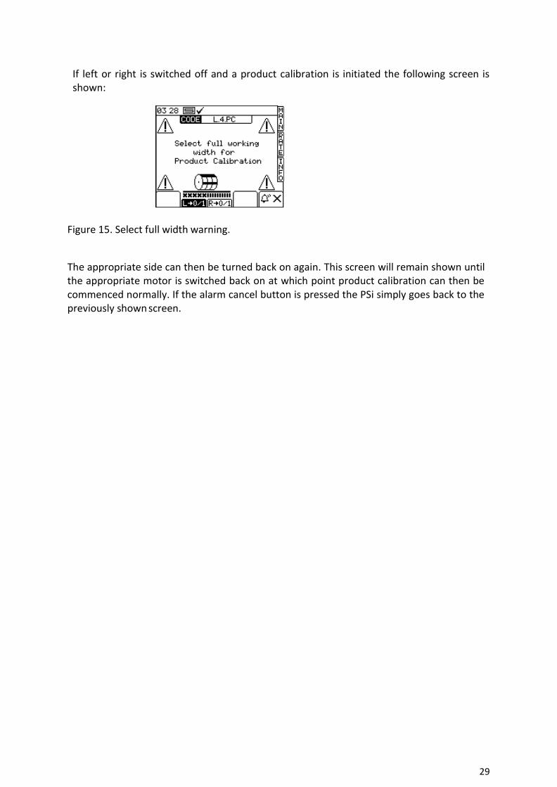
If left or right is switched off and a product calibration is initiated the following screen is shown:
Figure 15. Select full width warning.
The appropriate side can then be turned back on again. This screen will remain shown until the appropriate motor is switched back on at which point product calibration can then be commenced normally. If the alarm cancel button is pressed the PSi simply goes back to the previously shown screen.

30
1.12 Product calibration
Initial product calibration
Set up the drill in the usual way for a bucket test.
1. From the SETUP screen, press the key.
2a. If the instrument is configured for dual products, first select the product you want to calibrate (Fig.16).
Figure 16. Dual product/Single metering
2b. Or if configured for dual metering, select the metering unit to be calibrated (Fig. 17).
Figure 17. Single Product/Dual metering
3. Otherwise, select the desired units then enter the weight required to be metered out (Fig.18) and press ENTER. The metering unit will then operate at the programmed calibration speed to dispense the correct amount of prod-uct, then stops. The instrument then displays a weight figure based on the existing programmed product calibration factor.
NOTE: If a priming switch is employed for calibration the calibration routine will commence from Fig. 16.
4. Weigh the contents of the container, and then enter the ACTUAL weight dispensed (Fig.20) and press ENTER to confirm.

31
5. Press ENTER again for the instrument to re-calculate and display the new cali-bration factor in kg/rev, the error %, and the maximum forward speed that is permissible based on the application rate set for the product (Fig.21).
Figure 21. Calibration confirmation screen
Figure 20. Calibration correction screen
Figure 19. During calibration screen
Figure 18. Pre-calibration screen
NOTE: The heading will be either SEED
/ FERT / LEFT / RIGHT according to
steps 2a , 2b.

32
6. Press ENTER again to confirm and store the new calibration factor, or press ESC to return to the SETUP menu screen.
It is recommended to reset the PART TOTAL to zero before commencing drill-ing. This will enable you after drilling an area, to quantify any error in the cali-bration factor by logging the theoretical amount of product used against a known amount used (a whole bag for example).
You can then adjust the calibration factor precisely, if necessary.
1.12.1 ‘CALIBRATION NUDGE’ - Adjusting the calibration factor
The ‘calibration nudge’ procedure enables you to adjust the existing calibration factor without having to redo a bucket test.
1. First note down the PART TOTAL for the product displayed in the INFO screen. This is the theoretical quantity that the instrument has calculate From the SETUP menu, press either the key (CAL. CHECK), or the key (DRILL SETUP). If the instrument is configured for dual products, first select the product you want to calibrate (Fig.16). If configured for dual metering units, likewise, first select the left or right unit (Fig.16)
2. From either screen, press the key to select the ‘Calibration Nudge’ screen (Fig.22).
Figure 22. Calibration nudge screen
Figure 23. Enter amount screen
Figure 24. Nudge confirmation data

33
Low fan speed
High fan speed
Hopper level alarm
3. Enter the theoretical (‘Expected’) weight noted from the INFO screen at step 1 and press ENTER twice.
1. Enter the actual weight dispensed and press ENTER twice.
2. The “cal” factor is re-calculated and displayed along with the % error and maximum forward speed (Fig.24). Press ENTER again to store the new factor.
1.13 Set Fan Speed and Hopper Level alarm thresholds
To view the alarm thresholds (Fig. 25), from the SETUP menu, press the key.
Figure 25. Alarm set up screen
To adjust the threshold, simply enter the figure and press the ENTER key.
34
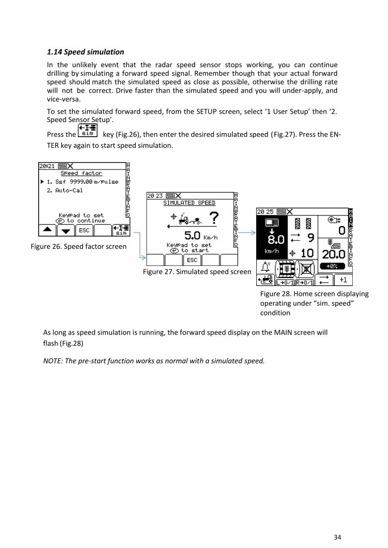
1.14 Speed simulation
In the unlikely event that the radar speed sensor stops working, you can continue drilling by simulating a forward speed signal. Remember though that your actual forward speed should match the simulated speed as close as possible, otherwise the drilling rate will not be correct. Drive faster than the simulated speed and you will under-apply, and vice-versa.
To set the simulated forward speed, from the SETUP screen, select ‘1 User Setup’ then ‘2. Speed Sensor Setup’.
Press the key (Fig.26), then enter the desired simulated speed (Fig.27). Press the EN-
TER key again to start speed simulation.
Figure 26. Speed factor screen
Figure 27. Simulated speed screen
Figure 28. Home screen displaying operating under “sim. speed” condition
As long as speed simulation is running, the forward speed display on the MAIN screen will
flash (Fig.28)
NOTE: The pre-start function works as normal with a simulated speed.

35
1.15 Select units / Rate step%
From the SETUP screen, select ‘1 User Setup’ then ‘3. Customise’.
Figure 29. Rate units screen
If the instrument is configured for dual products, first select the product with the
LEFT/RIGHT arrow keys (Fig.29).
Use the UP/DOWN arrow keys to select the parameter.
Use the LEFT/RIGHT arrow key to select the units (kg/ha or seeds/m2).
Use either the LEFT/RIGHT arrow keys to adjust the rate, or simply enter the desired figure
using the keypad and press ENTER to confirm
1.15.1 Speed Auto-cal. routine
This procedure is required to calibrate the radar for the location it is positioned in. Certain
machines have differing positions and proximity to the ground. Tractor pickup hitch, drawbar
fluctuations etc. can all affect the perceived forward speed signal.
1. Press the red button
2. Press “1” user setup
3. Press “2” speed sensor factor
4. Go down to option 2 and press enter. N.B. At this point, you can manually edit option 1, the SSF as displayed.
Figure 30. Main menu screens
36
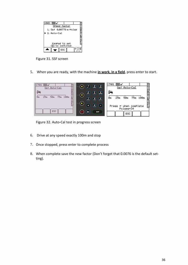
Figure 31. SSF screen
5. When you are ready, with the machine in work, in a field, press enter to start.
Figure 32. Auto-Cal test in progress screen
6. Drive at any speed exactly 100m and stop
7. Once stopped, press enter to complete process
8. When complete save the new factor (Don’t forget that 0.0076 is the default set-ting).

37
1.16 GPS Configuration Hardware/software set up Procedure to receive a GPS speed signal and variable seed rate signal
Outline procedure: 1. Port set up 2. Baud rate (match GPS device
to the RDS box) 3. Select the speed sensor option.
To use GPS, choose NMEA VTG, option 4 to use the radar, choose option 3
4. Load Variable rate maps from the log page
1.16.1 Port cable configuration
Figure 34. Typical Setup – Psi sending rate instructions via SD card
Top Port options
GPS – e.g. GPS 16 or any compatible receiver
Bottom Port options
Receiving VRT instructions from OEM controller
e.g. Fieldstar Type 1
Soyl Opti Agro-
com ACT Yara-
N Sensor
receiving VRT instructions from SD card
e.g. RDS PF MODULE Figure 33. Port connections
Top port
Card
GPS Data
Card
GPS Receiver
Receiver
Custom interface cable
Card
38
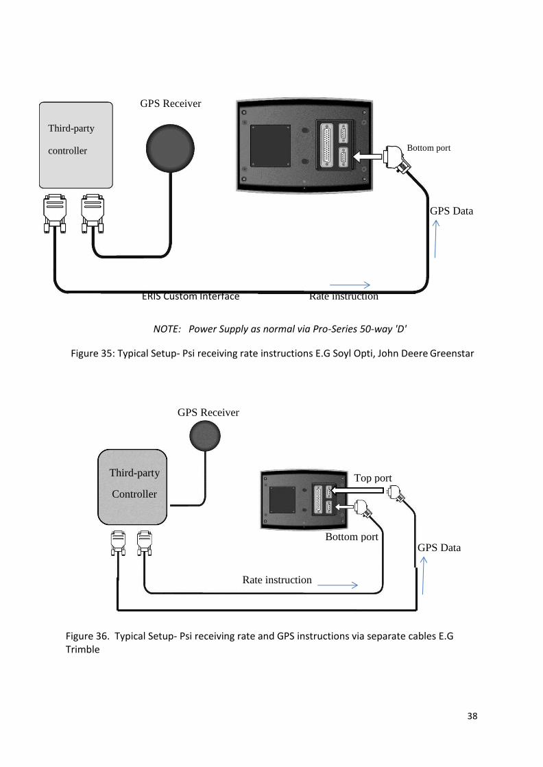
NOTE: Power Supply as normal via Pro-Series 50-way 'D'
Figure 35: Typical Setup- Psi receiving rate instructions E.G Soyl Opti, John Deere Greenstar
Figure 36. Typical Setup- Psi receiving rate and GPS instructions via separate cables E.G Trimble
GPS Receiver
Third-party
Controller
Rate instruction
ERIS Custom Interface Rate instruction
Third-party
controller
GPS Receiver
Receiver
Bottom port
Receiver
Bottom port
Top port
GPS Data
GPS Data

39
1.16.2 Head Unit Configuration - Port Settings Having connected the hardware to the appropriate port(s), you need to configure the port settings.
Press to select SETUP, then:
Figure 37. Configuring the ports process and screen
The ‘Ports Setup’ screen can also be accessed via the Technician Config menu (PIN=1234). Use the arrow keys to select the correct option and press ENTER to confirm.
Top Port Function
NOT USED Factory default setting
GPS ONLY GPS input for a standalone RDS P.F. control system
GPS + AMATRON PLUS
Third-party interface:
GPS input + sending Variable-rate Treatment (VRT) instructions to an OEM third-party rate controller.
GPS + BOGBALLE
GPS + LH5000 v.4
GPS + KVERNELAND
GPS + RAVEN
GPS + FIELDSTAR
Bottom Port *
NOT USED Factory default setting
RDS PRINTER ICP200 Printing Field Summary data / Calibration data
PC DOWNLOAD Output via cable to PC
RDS PF MODULE Enables the internal Data Card Module
Using an (older) external RDS Data Card Module
FIELDSTAR TYPE 1
Third-party interface:
Receiving Variable-rate Treatment (VRT) instruc-tions from an OEM third-party rate controller.
AGROCOM ACT
YARA N-SENSOR
JD GREENSTAR
RAVEN 4800
RAVEN 9600
Figure 38. Port Options *inserting a data card disables the bottom port
5. GENERAL PF
6. PORTS SETUP

40
1.16.3 Internal Data Card Module
Figure 39. SD Data Card Module
The internal data card reader accepts SD/MMC cards of up to 2Gb, to store data generated from
harvesting, soil sampling, or variable-rate treatment. It can also upload data e.g. treatment
plans or navigation data for soil sampling.
Typically, a 64Mb card can store data for up 2500 hectares.
Cards must have a directory called "Rds_data.xxx" in which all data is stored and retrieved. This di-
rectory should be automatically created when you first insert the card into the Data Module. All PF
data is written to this directory. If the folder "Rds_data.xxx" is not created automatically, manually
create it in the normal way from Explorer.
NOTE: The bottom port is disabled when an SD card is inserted in the internal data card module. On
removing the card, the port will revert to the function configured on the PORT SETUP screen (Fig.38).

41
1.16.4 GPS Receiver
‘GPS 16’ GPS Receiver RDS’s own GPS receiver for GPS position and speed comes fitted
with a magnetic base. Mounting on a plastic roof will require a metal
base plate (not included) to be attached by suitable means. Run the
combined antenna/power cable into the cab.
Connect the lead directly to the top port.
NOTE: The lead also powers the unit.
Figure 40. RDS GPS receiver
Pro-Series port settings:
Top Port: ‘GPS ONLY’
GPS Baudrate: 9600
After the initial power-on, allow up to 5 minutes for the receiver to automatically establish its position. Subsequently the unit should establish position more quickly. NOTE: The GPS icon at the top of the display indicates the status of the GPS signal.
Third-party GPS Receivers Any DGPS receiver may be used if the output is compatible with the head unit.
Changing the GPS baud rate.
Your existing GPS lead will not work if connected directly to the head unit. Connect it to the top port via the ‘Pro-Series-Jupiter’ lead Pt. No. S/CB/268-1-045.
NOTE 1: The GPS requires a separate power supply from a suitable switched-12V source.
NOTE 2: If sending VRT instructions to a third-party controller, the top port shares DGPS data in and VRT data out via a custom lead.

42
1.16.5 GPS Baud Rate
The RDS box needs to be configured as shown below to match the baud rate with the 3rd
party GPS receiver to be compatible. The RDS Default = 4800.
Figure 41. Baudrate setting
1.16.6 GPS Configuration To enable the GPS to be used:
From the main SETUP menu, select option 5. GEN-ERAL PF SETUP. Select 6. Ports Setup using the arrow keys below the screen set the TOP PORT to ‘GPS Only’.
If using an RDS GPS 16, select 5. GPS Baudrate and en-sure that the baud rate is set to 9600. If a different GPS is being used then this speed must be established prior to configuration.
Figure 42. Enabling GPS
If the GPS is communicating correctly then a tick will be shown in the top header bar.
GPS Status:
= No position
= Position/no difference

43
1.17 Data Logging and Variable Rate Treatment
Data Logging and Variable Rate control functions are accessed from the SETUP screen.
1. Press the key to display the logging screen (Fig.43). The instrument then detects the
presence of the data card.
2. Press the START key to select the JOB STARTUP page (Fig.44).
You are presented with a number of options. Only options 1,2 and 3 are applicable to the
Artemis.
1. APPLY FROM PLAN (Variable-Rate Treatment or ‘VRT’)
(a) The Pro-Series receives the rate from a treatment plan on the RDS Data Card Mod-ule and controls the application via the RDS control system. A full application rec-ord of the actual application is generated and saved on the Data Module.
(b) The Pro-Series receives the rate from a treatment plan on the RDS Data Card Mod-ule and sends it to a third party controller, which controls the application via an OEM control system (System ERIS).
(c) The Pro-Series receives the rate from a third-party controller and controls the application via the RDS control system (System ERIS). The Pro-Series can send back the actual application rate to the other controller
All setups allow the operator to commence a full VRT application.
For (a) and (b) a full application record of the actual application is generated and saved on the Data Module. The associated work record file can be viewed in the mapping/treatment plan software. Job summary data (iii) is also appended to the work record file.
2. LOG TREATMENT (Dynamic Data Logging)
A full application record is generated, logging rate and other parameters (e.g. "tags") in real time, attributing this data to a specific location. The associated "Dy-namic Logging" file is viewed in the mapping/treatment plan software. A large amount of data is generated by dynamic logging and therefore must be saved onto an RDS Data Card Module. Job summary data (iii) is also appended to the dynamic
Figure 43. Logging screen
Figure 44. Start-up page
Options ap-
plicable to
Artemis
44
logging file.
3. LOG SUMMARY ONLY (Field Data Logging)
For simple farm record keeping and traceability purposes, you can record a sum-mary of each job or work session in the internal memory, and subsequently down-load directly to a PC, to a Data Module, or print to a printer. The amount of summary data for each job is small, and is saved in the internal memory. The instrument can store up to 75 individual job summaries.
2.0 Maintenance Low maintenance requirements were an important design consideration when developing
this Front Hopper and every effort has been made to minimise input requirements on the
operator. However, there are several areas to look at to ensure the most efficient use of the
machine continues.
2.1 Hydraulics
After the first 5 hours work, it is advisable to check all hydraulic fittings are tight and free from
leaks.
To protect the delicate internal valves and seals throughout the hydraulic circuits, it is im-
portant to clean all hydraulic hose quick release coupler (QRC) probes before inserting them
into the tractor.
2.2 Greasing
Coulter rams are fitted with a grease point at either end and require greasing every 50 hours. The wing pivot points and each end of the wing fold rams should also be greased every 50 hours.
Main pivot points such as the axle pivots, both ends of the main lift rams, the bout marker knuckle joint pivot and marker ram should be greased every 10 hours.
2.3 Winter storage
When machines are to be parked up for the winter period, correct storage techniques are an important part of protecting the machine and ensuring hassle free future drilling cam-paigns.
The design of the metering system relies on a pressurized tank. Prior to washing the drill off,
it is advisable to inspect the tank joints and seams for any evidence that the seal has been
compromised.
When the machine has finished work it should be cleaned down and washed off to remove all traces of soil and debris. When washing off, ensure bearings are not exposed to water ingress. The tank, the metering system and all seed transfer channels should be
45
entirely cleared of surplus seed. It is advisable to remove the nylon insert from the metering system and leave the bottom open. Ideally the drill should be stored inside.
Following washing off, grease points, located throughout the machines should receive two or three pumps of grease to push water out.
When the machine is parked up, a note should be made of the wearing parts that require replacing ready for the next seasons work. The wearing parts can then be ordered in time ready for the next season’s work in good time. When ordering replacement parts please have your serial number, part numbers and quantities at hand.
3.0 Hydraulic Systems
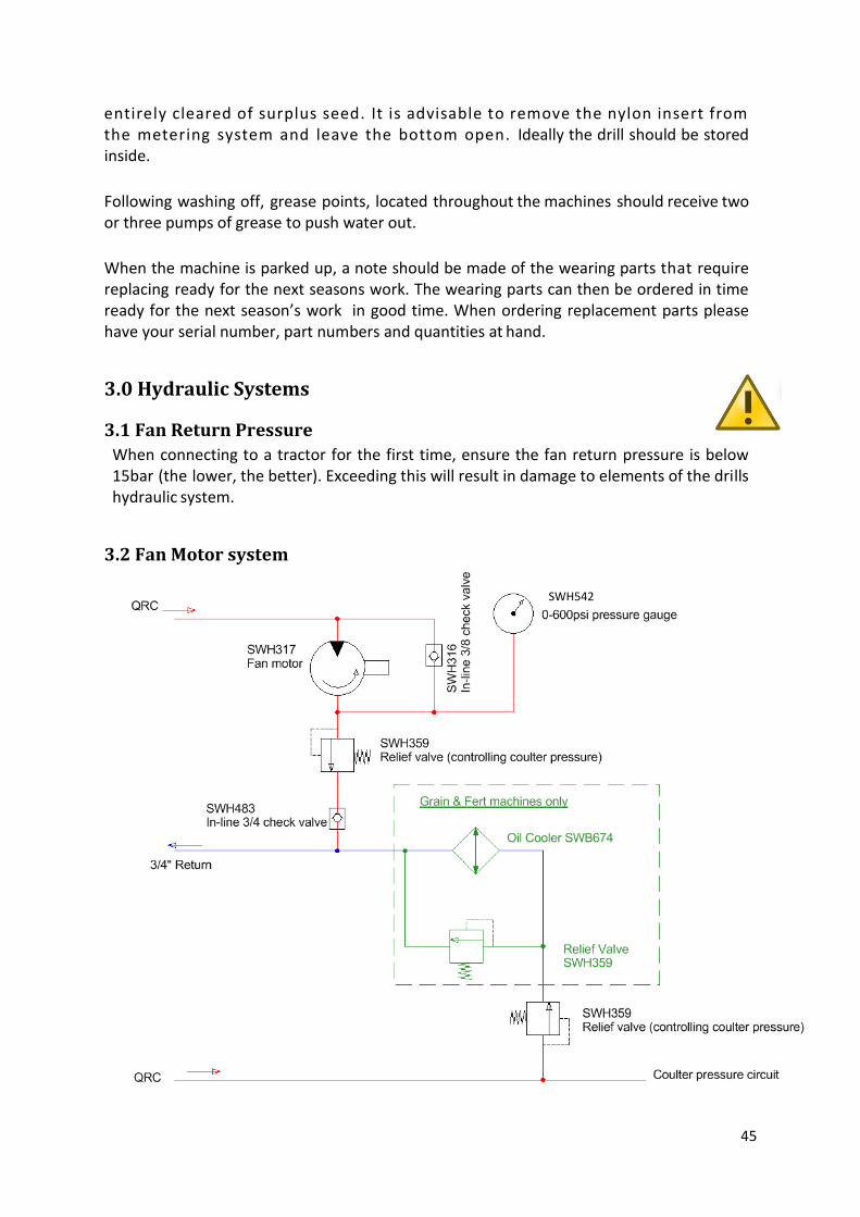
3.1 Fan Return Pressure
When connecting to a tractor for the first time, ensure the fan return pressure is below 15bar (the lower, the better). Exceeding this will result in damage to elements of the drills hydraulic system.
3.2 Fan Motor system
SWH542

46
4.0 Operation & Adjustment
4.1 Fan adjustment
If it is found that the fan speed cannot be adjusted finely enough due to the increment being too large on the tractor spool, there is a needle value located at the bulk head end of the hydraulic pipe that feeds the fan. The adjustment should be carried out by, setting the fan speed slightly higher than desired and then reducing the flow of oil by rotating the needle valve (FCV) clockwise. If the tractor spool is providing the correct oil flow for the desired fan speed then the needle valve should be adjusted so that it is fully open.
Figure 48. 3m Drill fan speed FCV
4.2 Finger Switch
Accurate positioning of the finger switch is important in order to ensure seeding commences and ceases at the correct moment. It is highly recommended to manually feel for the “click” on the finger switch to ascertain the angle of the spring at which point the switch cuts in and out. This knowledge should then be applied to the position of the finger switch against the top link. Failure to set this up correctly could result in delayed starts and delayed stops, sub-sequently resulting in underseeded areas at the beginning of a run and overseeding at the ends once lifted out of work.
4.3 Front Hopper Overview
The Front Hopper gives the capability to apply grain or fertiliser directly to the optimum po-
sition for the seed. This saves on fertiliser costs as the DD applies the fertiliser into the same
channel/furrow as the seed, where traditionally the fertiliser would be applied to the entire
surface area of the field. The system allows for large savings in running costs by combining
seedbed preparation, seed and fertiliser application in one pass.
47
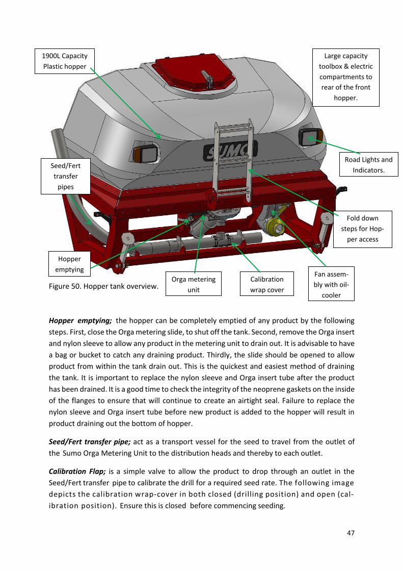
Figure 50. Hopper tank overview.
Hopper emptying; the hopper can be completely emptied of any product by the following
steps. First, close the Orga metering slide, to shut off the tank. Second, remove the Orga insert
and nylon sleeve to allow any product in the metering unit to drain out. It is advisable to have
a bag or bucket to catch any draining product. Thirdly, the slide should be opened to allow
product from within the tank drain out. This is the quickest and easiest method of draining
the tank. It is important to replace the nylon sleeve and Orga insert tube after the product
has been drained. It is a good time to check the integrity of the neoprene gaskets on the inside
of the flanges to ensure that will continue to create an airtight seal. Failure to replace the
nylon sleeve and Orga insert tube before new product is added to the hopper will result in
product draining out the bottom of hopper.
Seed/Fert transfer pipe; act as a transport vessel for the seed to travel from the outlet of
the Sumo Orga Metering Unit to the distribution heads and thereby to each outlet.
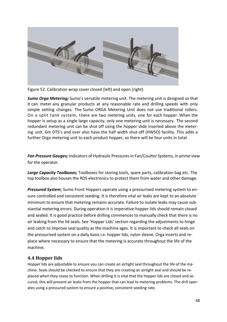
Calibration Flap; is a simple valve to allow the product to drop through an outlet in the
Seed/Fert transfer pipe to calibrate the drill for a required seed rate. The following image
depicts the calibration wrap-cover in both closed (drilling position) and open (cal-
ibration position). Ensure this is closed before commencing seeding.
1900L Capacity
Plastic hopper
Hopper
emptying
Seed/Fert
transfer
pipes
Calibration
wrap cover
Orga metering
unit
Road Lights and
Indicators.
Fan assem-
bly with oil-
cooler
Large capacity
toolbox & electric
compartments to
rear of the front
hopper.
Fold down
steps for Hop-
per access
48
Figure 52. Calibration wrap cover closed (left) and open (right)
Sumo Orga Metering; Sumo’s versatile metering unit. The metering unit is designed so that it can meter any granular products at any reasonable rate and drilling speeds with only simple setting changes. The Sumo ORGA Metering Unit does not use traditional rollers. On a split tank system, there are two metering units, one for each hopper. When the hopper is setup as a single large capacity, only one metering unit is necessary. The second redundant metering unit can be shut off using the hopper slide inserted above the meter-ing unit. 6m DTS’s and over also have the half width shut-off (HWSO) facility. This adds a further Orga metering unit to each product hopper, so there will be four units in total.
Fan Pressure Gauges; Indicators of Hydraulic Pressures in Fan/Coulter Systems, in prime view
for the operator.
Large Capacity Toolboxes; Toolboxes for storing tools, spare parts, calibration bag etc. The top toolbox also houses the RDS electronics to protect them from water and other damage. Pressured System; Sumo Front Hoppers operate using a pressurised metering system to en-
sure controlled and consistent seeding. It is therefore vital air leaks are kept to an absolute
minimum to ensure that metering remains accurate. Failure to isolate leaks may cause sub-
stantial metering errors. During operation it is imperative hopper lids should remain closed
and sealed. It is good practice before drilling commences to manually check that there is no
air leaking from the lid seals. See ‘Hopper Lids’ section regarding the adjustments to hinge
and catch to improve seal quality as the machine ages. It is important to check all seals on
the pressurised system on a daily basis i.e. hopper lids, nylon sleeve, Orga inserts and re-
place where necessary to ensure that the metering is accurate throughout the life of the
machine.
4.4 Hopper lids Hopper lids are adjustable to ensure you can create an airtight seal throughout the life of the ma-
chine. Seals should be checked to ensure that they are creating an airtight seal and should be re-
placed when they cease to function. When drilling it is vital that the hopper lids are closed and se-
cured, this will prevent air leaks from the hopper that can lead to metering problems. The drill oper-
ates using a pressured system to ensure a positive, consistent seeding rate.

49
To adjust the lid, loosen the locking nuts (highlighted in the cross section) on the underside of the
threaded pivots. The uppermost nut then can be adjusted up or down to achieve the appropriate
seal required for the system to work properly. It is important to tighten the locking nuts after the
appropriate setting is achieved. When adjusting the hinge, it is equally important to adjust the catch
in the same manner to create a consistent seal all around the rim. This can be done be loosening the
locking nut and adjusting the catch up or down in the same way as the hinge. Always remember to
tighten the locking nut once complete.
Figure 54. Hopper lid, open, closed and
seal detail.

50
4.5 Calibration Procedure
1. Open flap to allow seed to flow out of the Air Transfer Pipe directly be-low the ORGA Metering Outlet.
2. Switch the scales ON and check units (kg). Zero the scales with the weight of the calibration bag and hanger.
3. The calibration hanger and bag sup-plied with the drill can then be hooked onto the Air Transfer Pipe.
4. Press and hold the white prime but-ton. This will put the control box in calibration mode and start the mo-tor turning and metering seed.
5. Release the white prime button to
stop the motor when a suitable sample is collected.
Screen appearance during calibration.
Continued…….
Caution! Always Prime the ORGA Metering Unit before Calibration
Press and hold the Prime button near the metering unit. Then release the button
at the point where seed flows full and evenly from the outlet. Empty contents of
Calibration bag back into the hopper, Press ESC on Control Box, and then proceed.
51
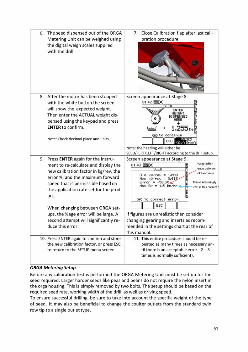
6. The seed dispensed out of the ORGA Metering Unit can be weighed using the digital weigh scales supplied with the drill.
7. Close Calibration flap after last cali-bration procedure
8. After the motor has been stopped
with the white button the screen will show the expected weight. Then enter the ACTUAL weight dis-pensed using the keypad and press ENTER to confirm. Note: Check decimal place and units
Screen appearance at Stage 8.
Note: the heading will either be SEED/FERT/LEFT/RIGHT according to the drill setup.
9. Press ENTER again for the instru-ment to re-calculate and display the new calibration factor in kg/rev, the error %, and the maximum forward speed that is permissible based on the application rate set for the prod-uct. When changing between ORGA set-ups, the %age error will be large. A second attempt will significantly re-duce this error.
Screen appearance at Stage 9. If figures are unrealistic then consider changing gearing and inserts as recom-mended in the settings chart at the rear of this manual.
10. Press ENTER again to confirm and store the new calibration factor, or press ESC to return to the SETUP menu screen.
11. This entire procedure should be re-peated as many times as necessary un-til there is an acceptable error. (2 – 3 times is normally sufficient).
ORGA Metering Setup
Before any calibration test is performed the ORGA Metering Unit must be set up for the seed required. Larger harder seeds like peas and beans do not require the nylon insert in the orga housing. This is simply removed by two bolts. The setup should be based on the required seed rate, working width of the drill as well as driving speed. To ensure successful drilling, be sure to take into account the specific weight of the type of seed. It may also be beneficial to change the coulter outlets from the standard twin row tip to a single outlet type.
%age differ-
ence between
old and new
Think! Alarmingly
low, is this correct?

4.6 Front Hopper Settings
This table is to be used as a guideline to assist in setting up the drill. Fine tuning may be needed depending on environment.
* - Internal inserts are supplied in long and short lengths. The longer insert approximately halves the rate that the notched slide lets through its aperture. They
also act as a guide to align the Sumo ORGA.
*** - The Gears supplied with the Sumo ORGA are specifically designed for the width of Drill that is specified. There will always be a small and a large
gear supplied.
**** Nylon insert not to be used
Crop Rape Rape Grass Linseed Cereals Cereals Cereals Cereals Cereals Beans**** Peas****
Drilling rate (kg/ha)
3 10 20 20 80 100 150 200 250 150 150/250
Insert * Long Long Short Short Short Short Short Short Short Short Short
Gear on Motor ***
Small Small Large Small Large Large Large Large Large Large Large
Gear on ORGA ***
Large Large Small Large Small Small Small Small Small Small Small
Min Fan speed (rpm)
1800 1800 1900 2200 2500 2600 2750 2900 3000 2500 2500
SAFETY NOTICE:
Never operate Sumo ORGA Metering without gear guard in place.
Never put any fingers into the Sumo ORGA Metering until unit is isolated
from the power.
Failure to do so may result in injury.

53
4.7 Orga Metering overview
Figure 56. Exploded metering unit
Up to 8m working widths it is recommended to operate the Orga metering unit with the nylon insert fitted for small seeds and cereals in order to prevent potential minor seed rate output fluctuations when drilling on gradients. When drilling fertilizer, peas, beans and other similarly large and hard seeds, the insert should be removed. In this circumstance, the void is critical to allow smooth seed flow.
SW1801 Outer
housing
SW1806 Choke
slide
Securing bolt
points
SWB724 Orga
flighting
SW1814 Orga
insert
SW2238 Nylon insert (fills
the void between the Orga
flighting and the Orga
housing).
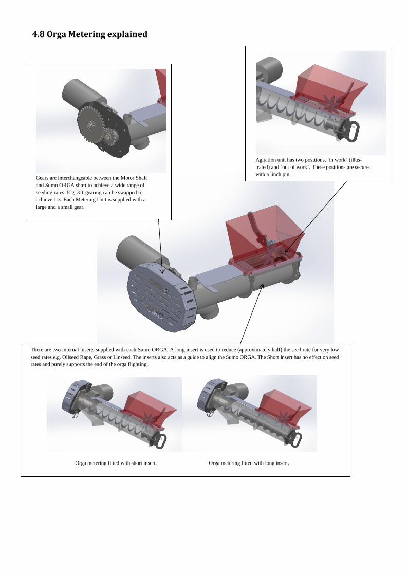
4.8 Orga Metering explained
Gears are interchangeable between the Motor Shaft
and Sumo ORGA shaft to achieve a wide range of
seeding rates. E.g 3:1 gearing can be swapped to
achieve 1:3. Each Metering Unit is supplied with a
large and a small gear.
Agitation unit has two positions, ‘in work’ (illus-
trated) and ‘out of work’. These positions are secured
with a linch pin.
There are two internal inserts supplied with each Sumo ORGA. A long insert is used to reduce (approximately half) the seed rate for very low
seed rates e.g. Oilseed Rape, Grass or Linseed. The inserts also acts as a guide to align the Sumo ORGA. The Short Insert has no effect on seed
rates and purely supports the end of the orga flighting..
Orga metering fitted with short insert. Orga metering fitted with long insert.

5.0 Parts Assembly overview The following pages display exploded sub-assembly drawings containing all the common com-
ponents and part numbers required as spare parts.