Embed Size (px)
Citation preview

140E
*MM156*www.tennantco.com
SweeperOperator and Parts Manual
MM156Rev. 22 (12-2006)
North America / International
(Electric)
This manual is furnished with each new model. It provides necessary operation and maintenance instructions.
Read this manual completely and understand the machine before operating or servicing it.
This machine will provide excellent service. However, the best results will be obtained at minimum costs if:
S The machine is operated with reasonable care.
S The machine is maintained regularly - per the machine maintenance instructions provided.
S The machine is maintained with manufacturer supplied or equivalent parts.
PROTECT THE ENVIRONMENTPlease dispose of packaging materials,old machine components such asbatteries, hazardous fluids such asantifreeze and oil, in an environmentallysafe way according to local wastedisposal regulations.
Always remember to recycle.
MACHINE DATAPlease fill out at time of installation for future reference.
Model No. --
Serial No. --
Machine Options --
Sales Rep. --
Sales Rep. phone no. --
Customer Number --
Installation Date --
Tennant CompanyPO Box 1452Minneapolis, MN 55440Phone: (800) 553--8033 or (763) 513--2850www.tennantco.com
Specifications and parts are subject to change without notice.
Copyright E 1984, 1986 -- 1992, 1994 -- 1997, 2000--2004, 2006 TENNANT Company, Printed in U.S.A.
GENERAL INFORMATION
i140E MM156 (3--02)
SAFETY PRECAUTIONS
The following symbols are used throughout thismanual as indicated in their descriptions:
WARNING: To warn of hazards or unsafepractices which could result in severepersonal injury or death.
FOR SAFETY: To identify actions which mustbe followed for safe operation of equipment.
The following information signals potentiallydangerous conditions to the operator orequipment. Read this manual carefully. Knowwhen these conditions can exist. Locate all safetydevices on the machine. Then, take necessarysteps to train machine operating personnel.Report machine damage or faulty operationimmediately. Do not use the machine if it is not inproper operating condition.
WARNING: Batteries Emit Hydrogen Gas.Explosion Or Fire Can Result. Keep SparksAnd Open Flame Away. Keep Covers OpenWhen Charging.
WARNING: Brush Throws Debris. Stop MotorBefore Lifting Hopper.
WARNING: Machine Moves When Motor IsRunning. Stop Motor Before Leaving Machine.
FOR SAFETY:
1. Do Not Operate Machine:-- Unless Trained And Authorized.-- Unless Operation Manual Is Read
And Understood.-- In Flammable Or Explosive Areas
Unless Designed For Use In ThoseAreas.
-- In Areas With Possible Falling ObjectsUnless Equipped With OverheadGuard.
2. Before Starting Machine:-- Make Sure All Safety Devices Are In
Place And Operate Properly.
3. When Using Machine:-- Go Slow On Grades And Slippery
Surfaces.-- Use Care When Backing Machine.-- Do Not Carry Riders On Machine.-- Always Follow Safety And Traffic
Rules.
4. Before Leaving Or Servicing Machine:-- Stop On Level Surface.-- Turn Off Machine And Remove Key.
5. When Servicing Machine:-- Avoid Moving Parts. Do Not Wear
Loose Jackets, Shirts, Or SleevesWhen Working On Machine.
-- Block Machine Tires Before JackingMachine Up.
-- Jack Machine Up At DesignatedLocations Only. Block Machine UpWith Jack Stands.
-- Use Hoist Or Jack That Will SupportThe Weight Of The Machine.
-- Wear Eye And Ear Protection WhenUsing Pressurized Air Or Water.
-- Disconnect Battery ConnectionsBefore Working On Machine.
-- Avoid Contact With Battery Acid.-- Use TENNANT Supplied Or Equivalent
Replacement Parts.
6. When Loading/Unloading MachineOnto/Off Truck Or Trailer:-- Turn Off Machine.-- Use Truck Or Trailer That Will Support
The Weight Of The Machine.-- Use Winch. Do Not Push The Machine
Onto/Off The Truck Or Trailer UnlessThe Load Height Is 380 mm (15 in) OrLess From The Ground.
-- Block Machine Tires.-- Tie Machine Down To Truck Or Trailer.
GENERAL INFORMATION
140E MM156 (6--91)ii
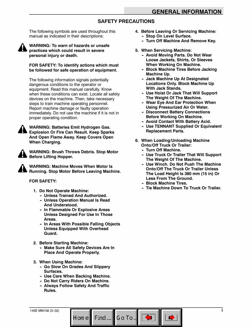
The following safety labels are mounted on themachine in the locations indicated. If these or anylabel becomes damaged or illegible, install a newlabel in its place.
MACHINE CREEPING WARNING LABEL --LOCATED ON MACHINE HANDLE FRAME.
FOR SAFETY LABEL -- LOCATED ONMACHINE HANDLE FRAME.
01189
HAZARD CHARGING LABEL -- LOCATED ONBATTERY COVER.
FLYING DEBRIS WARNING LABEL --LOCATED ON TOP OF HOPPER.

GENERAL INFORMATION
iii140E MM156 (3--02)
CONTENTS
PageGENERAL INFORMATION i. . . . . . . . . . . . . .
SAFETY PRECAUTIONS i. . . . . . . . . . . .
SPECIFICATIONS 1-1. . . . . . . . . . . . . . . . . . . . .MACHINE SPECIFICATIONS 1-3. . . . . . . . .
POWER TYPE 1-3. . . . . . . . . . . . . . . . . . .POWER TRAIN 1-3. . . . . . . . . . . . . . . . . .SUSPENSION SYSTEM 1-3. . . . . . . . . .GENERAL MACHINE
DIMENSIONS/CAPACITIES 1-3. . . .MACHINE WEIGHTS 1-3. . . . . . . . . . . . .GENERAL MACHINE
PERFORMANCE 1-3. . . . . . . . . . . . . .MACHINE DIMENSIONS 1-4. . . . . . . . . . . . .
OPERATION 2-1. . . . . . . . . . . . . . . . . . . . . . . . . .PREPARATION FOR OPERATION 2-3. . . .OPERATION OF CONTROLS 2-4. . . . . . . .
MACHINE COMPONENTS 2-4. . . . . . . .CLUTCH CONTROL HANDLE 2-5. . . . .MAIN BRUSH LIFT HANDLE 2-5. . . . . .SIDE BRUSH 2-5. . . . . . . . . . . . . . . . . . . .MAIN BRUSH REMOVAL LEVER 2-5. .BATTERY COVER 2-6. . . . . . . . . . . . . . . .MASTER POWER SWITCH 2-6. . . . . . .SHAKER RESET PUSHBUTTON 2-6. . .CLEAN FILTER PUSHBUTTON 2-6. . . .MACHINE CIRCUIT BREAKER 2-6. . . .CHARGER TIMER SWITCH 2-7. . . . . . .CHARGER PANEL 2-7. . . . . . . . . . . . . . .HOUR METER 2-7. . . . . . . . . . . . . . . . . . .CHARGING RATE GAUGE 2-7. . . . . . . .
MACHINE OPERATION 2-8. . . . . . . . . . . . . .NORMAL SWEEPING OPERATION 2-8
PRE-START CHECKLIST 2-8. . . . . . .TO START MACHINE 2-8. . . . . . . . . .TO SWEEP 2-8. . . . . . . . . . . . . . . . . . .TO DUMP HOPPER 2-9. . . . . . . . . . .POST OPERATION CHECKLIST --
MOTOR OPERATING 2-9. . . .TO STOP MACHINE 2-9. . . . . . . . . . .POST OPERATION CHECKLIST --
MOTOR STOPPED 2-9. . . . . .MACHINE TROUBLESHOOTING 2-10. .
MACHINE STORAGE 2-11. . . . . . . . . . . . . . . .STORING MACHINE 2-11. . . . . . . . . . . . .
PageMAINTENANCE 3-1. . . . . . . . . . . . . . . . . . . . . . .
RECOMMENDED FIRST 20-HOURMACHINE INSPECTION 3-3. . . . . . . . . .
MAINTENANCE CHART 3-4. . . . . . . . . . . . .ELECTRICAL SYSTEM 3-6. . . . . . . . . . . . . .
BATTERIES 3-6. . . . . . . . . . . . . . . . . . . . .BATTERY CHARGING 3-7. . . . . . . . . . . .
TO CHARGE BATTERIES (Formachines below serial number009737) 3-7. . . . . . . . . . . . . . . . . . .
TO CHARGE BATTERIES (Formachines serial number 009737and above) 3-8. . . . . . . . . . . . . . . . .
ELECTRICAL SCHEMATIC (For machinesbelow serial number 009737) 3-10.
ELECTRICAL SCHEMATIC (Formachines serial number 009737and above) 3-11. . . . . . . . . . . . . . . . . . . .
BRUSHES 3-12. . . . . . . . . . . . . . . . . . . . . . . . . .MAIN BRUSH 3-12. . . . . . . . . . . . . . . . . . . .
TO REMOVE MAIN BRUSH 3-12. . . .TO INSTALL MAIN BRUSH 3-12. . . . .TO CHECK AND ADJUST MAIN
BRUSH PATTERN 3-13. . . . . . . . . .SIDE BRUSH 3-14. . . . . . . . . . . . . . . . . . . .
TO REMOVE SIDE BRUSH 3-14. . . . .TO INSTALL SIDE BRUSH 3-14. . . . .TO ADJUST SIDE BRUSH 3-14. . . . . .
DEBRIS HOPPER AND DUST FILTER 3-15.DEBRIS HOPPER 3-15. . . . . . . . . . . . . . . .
TO EMPTY HOPPER 3-15. . . . . . . . . .TO ADJUST HOPPER FLOOR
CLEARANCE 3-15. . . . . . . . . . . . . .REAR GUIDE WHEELS 3-16. . . . . . . . . . .
TO ADJUST REAR GUIDEWHEELS 3-16. . . . . . . . . . . . . . . . . .
HOPPER DUST FILTER 3-16. . . . . . . . . . .TO REMOVE DUST FILTER 3-17. . . .TO INSTALL DUST FILTER 3-17. . . . .
SKIRTS AND SEALS 3-18. . . . . . . . . . . . . . . .SIDE DUST SKIRTS 3-18. . . . . . . . . . . . . .
TO ADJUST SIDE DUST SKIRTS 3-18TO REPLACE SIDE DUST
SKIRTS 3-18. . . . . . . . . . . . . . . . . . .HOPPER SIDE SEALS 3-19. . . . . . . . . . . .
TO REPLACE HOPPER SIDESEALS 3-19. . . . . . . . . . . . . . . . . . . .
REAR BRUSH SKIRT 3-19. . . . . . . . . . . . .TO REPLACE REAR BRUSH
SKIRT 3-19. . . . . . . . . . . . . . . . . . . . .
GENERAL INFORMATION
140E MM156 (8--01)iv
PageBELTS AND CHAINS 3-20. . . . . . . . . . . . . . . .
FLAT PROPELLING BELT 3-20. . . . . . . . .TO CHECK AND ADJUST FLAT
PROPELLING BELT 3-20. . . . . . . .TO REPLACE FLAT PROPELLING
BELT 3-20. . . . . . . . . . . . . . . . . . . . . .MOTOR DRIVE BELT 3-21. . . . . . . . . . . . .
TO CHECK AND ADJUSTMOTOR DRIVE BELT 3-21. . . . . . .
TO REPLACE MOTOR DRIVEBELT 3-22. . . . . . . . . . . . . . . . . . . . . .
BRUSH DRIVE BELT 3-23. . . . . . . . . . . . .TO REPLACE BRUSH DRIVE
BELT 3-23. . . . . . . . . . . . . . . . . . . . . .SIDE BRUSH DRIVE BELT 3-24. . . . . . . .
TO ADJUST SIDE BRUSHDRIVE BELT 3-24. . . . . . . . . . . . . . .
TO REPLACE SIDE BRUSHDRIVE BELT 3-24. . . . . . . . . . . . . . .
STATIC DRAG CHAIN 3-24. . . . . . . . . . . .PUSHING AND TRANSPORTING THE
MACHINE 3-25. . . . . . . . . . . . . . . . . . . . . . . .PUSHING THE MACHINE 3-25. . . . . . . . .TRANSPORTING THE MACHINE 3-25. .
APPENDIX 4-1. . . . . . . . . . . . . . . . . . . . . . . . . . . .HARDWARE INFORMATION 4-3. . . . . . . . .
STANDARD BOLT TORQUE CHART 4-3METRIC BOLT TORQUE CHART 4-3. .BOLT IDENTIFICATION 4-3. . . . . . . . . . .THREAD SEALANT AND LOCKING
COMPOUNDS 4-3. . . . . . . . . . . . . . . .
HOW TO USE THIS MANUAL 5--1. . . . . . . . . . .IMPORTANT INFORMATION 5--1. . . . . . . . .FINDING A TENNANT PART NUMBER 5--2PLACING AN ORDER 5--3. . . . . . . . . . . . . . .
STANDARD MODEL PARTS 6-1. . . . . . . . . . . . . .Fig. 1 -- Recommended General
Maintenance Items 6-3. . . . . . .Fig. 2 -- Replacement Brushes 6-6. . . . . . . .Fig. 3 -- Main Frame and Charger
Group 6-6. . . . . . . . . . . . . . . . . .Fig. 4 -- Handle Group 6-8. . . . . . . . . . . . . . .Fig. 5 -- Hopper Assembly 6-9. . . . . . . . . . . .Fig. 6 -- Brush Drive Group 6-10. . . . . . . . . . .Fig. 7 -- Motor and Wheel Drive Group 6-12.Fig. 8 -- Filter Group 6-14. . . . . . . . . . . . . . . . . .Fig. 9 -- Battery Group 6-16. . . . . . . . . . . . . . .Fig. 10 -- Wire Harnesses Group 6-18. . . . . . .Fig. 11 -- Vacuum Fan Group 6-20. . . . . . . . . .Fig. 12 -- Label Kit 6-21. . . . . . . . . . . . . . . . . . .
OPTIONS 7-1. . . . . . . . . . . . . . . . . . . . . . . . . . . . .Fig. 1 -- Side Brush Group 7-2. . . . . . . . . . . . . .Fig. 2 -- Lifting Bracket Kit 7-4. . . . . . . . . . . . . .Fig. 3 -- Fine Particle Filter Kit 7-5. . . . . . . . . . .Fig. 4 -- Dual Carpet Lint Filter Kit 7-6. . . . . . . .
PageFig. 5 -- Ammeter Group 7-7. . . . . . . . . . . . . . . .Fig. 6 -- Grille Kit 7-8. . . . . . . . . . . . . . . . . . . . . .Fig. 7 -- Cord Kit 7-9. . . . . . . . . . . . . . . . . . . . . . .Fig. 8 -- Documentation Group 7-10. . . . . . . . .
CROSS REFERENCE 8-1. . . . . . . . . . . . . . . . . .PART NUMBER TO PAGE NUMBER
CROSS REFERENCE LIST 8-2. . . . . . . .PART DESCRIPTION TO PAGE NUMBER
CROSS REFERENCE LIST 8-4. . . . .
SPECIFICATIONS
1-1140E MM156 (3--88)
SECTION 1CONTENTS
PageMACHINE SPECIFICATIONS 1-3. . . . . . . . . . . .
POWER TYPE 1-3. . . . . . . . . . . . . . . . . . . . . .POWER TRAIN 1-3. . . . . . . . . . . . . . . . . . . . .SUSPENSION SYSTEM 1-3. . . . . . . . . . . . .GENERAL MACHINE
DIMENSIONS/CAPACITIES 1-3. . . . . . .MACHINE WEIGHTS 1-3. . . . . . . . . . . . . . . .GENERAL MACHINE PERFORMANCE 1-3
MACHINE DIMENSIONS 1-4. . . . . . . . . . . . . . . .
SPECIFICATIONS
140E MM156 (3--88)1-2
SPECIFICATIONS
1-3140E MM156 (12--00)
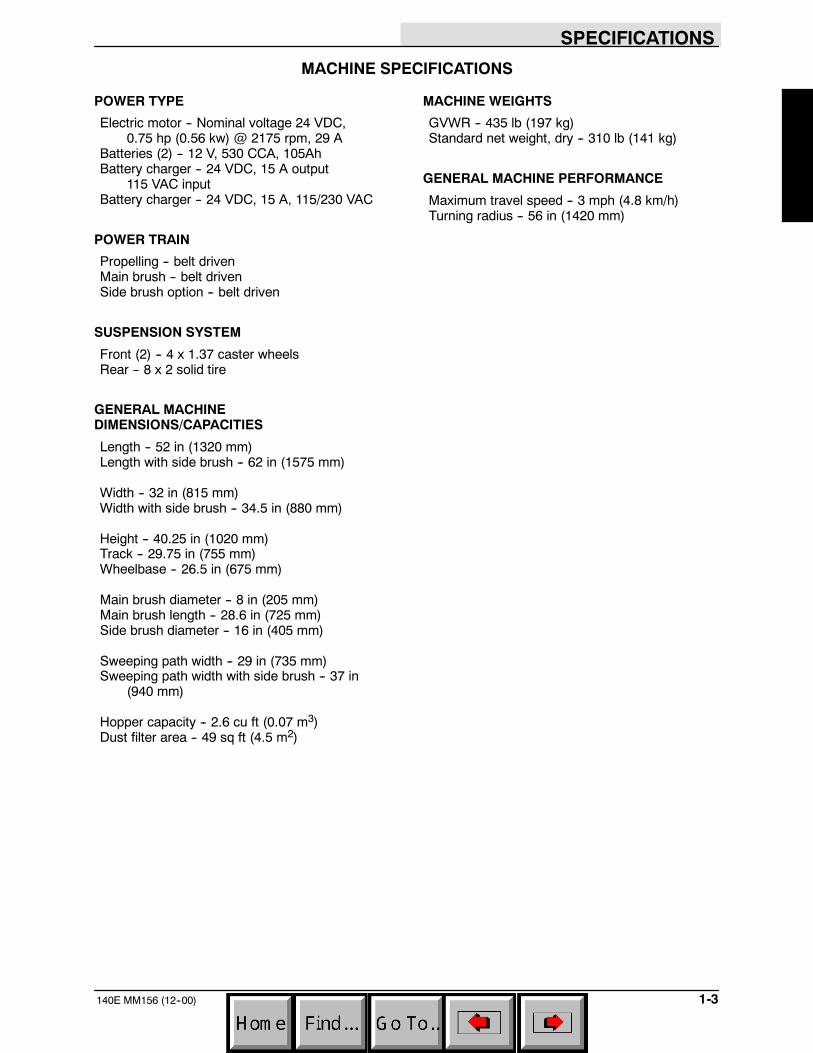
MACHINE SPECIFICATIONS
POWER TYPE
Electric motor -- Nominal voltage 24 VDC,0.75 hp (0.56 kw) @ 2175 rpm, 29 A
Batteries (2) -- 12 V, 530 CCA, 105AhBattery charger -- 24 VDC, 15 A output
115 VAC inputBattery charger -- 24 VDC, 15 A, 115/230 VAC
POWER TRAIN
Propelling -- belt drivenMain brush -- belt drivenSide brush option -- belt driven
SUSPENSION SYSTEM
Front (2) -- 4 x 1.37 caster wheelsRear -- 8 x 2 solid tire
GENERAL MACHINEDIMENSIONS/CAPACITIES
Length -- 52 in (1320 mm)Length with side brush -- 62 in (1575 mm)
Width -- 32 in (815 mm)Width with side brush -- 34.5 in (880 mm)
Height -- 40.25 in (1020 mm)Track -- 29.75 in (755 mm)Wheelbase -- 26.5 in (675 mm)
Main brush diameter -- 8 in (205 mm)Main brush length -- 28.6 in (725 mm)Side brush diameter -- 16 in (405 mm)
Sweeping path width -- 29 in (735 mm)Sweeping path width with side brush -- 37 in
(940 mm)
Hopper capacity -- 2.6 cu ft (0.07 m3)Dust filter area -- 49 sq ft (4.5 m2)
MACHINE WEIGHTS
GVWR -- 435 lb (197 kg)Standard net weight, dry -- 310 lb (141 kg)
GENERAL MACHINE PERFORMANCE
Maximum travel speed -- 3 mph (4.8 km/h)Turning radius -- 56 in (1420 mm)

SPECIFICATIONS
140E MM156 (6--00)1-4
MACHINE DIMENSIONS
TOP VIEW
SIDE VIEW
26.5 in(675 mm)
32 in(815 mm)
40.25 in(1020 mm)
52 in(1320 mm)
FRONT VIEW

OPERATION
2-1140E MM156 (6--91)
SECTION 2CONTENTS
PagePREPARATION FOR OPERATION 2-3. . . . . . .OPERATION OF CONTROLS 2-4. . . . . . . . . . .
MACHINE COMPONENTS 2-4. . . . . . . . . . .CLUTCH CONTROL HANDLE 2-5. . . . . . . .MAIN BRUSH LIFT HANDLE 2-5. . . . . . . . .SIDE BRUSH 2-5. . . . . . . . . . . . . . . . . . . . . . .MAIN BRUSH REMOVAL LEVER 2-5. . . . .BATTERY COVER 2-6. . . . . . . . . . . . . . . . . .MASTER POWER SWITCH 2-6. . . . . . . . . .SHAKER RESET PUSHBUTTON 2-6. . . . .CLEAN FILTER PUSHBUTTON 2-6. . . . . . .MACHINE CIRCUIT BREAKER 2-6. . . . . . .CHARGER TIMER SWITCH 2-7. . . . . . . . . .CHARGER PANEL 2-7. . . . . . . . . . . . . . . . . .HOUR METER 2-7. . . . . . . . . . . . . . . . . . . . . .CHARGING RATE GAUGE 2-7. . . . . . . . . . .
MACHINE OPERATION 2-8. . . . . . . . . . . . . . . . .NORMAL SWEEPING OPERATION 2-8. . .
PRE-START CHECKLIST 2-8. . . . . . . . .TO START MACHINE 2-8. . . . . . . . . . . . .TO SWEEP 2-8. . . . . . . . . . . . . . . . . . . . . .TO DUMP HOPPER 2-9. . . . . . . . . . . . . .POST OPERATION CHECKLIST --
MOTOR OPERATING 2-9. . . . . . . . . .TO STOP MACHINE 2-9. . . . . . . . . . . . . .POST OPERATION CHECKLIST --
MOTOR STOPPED 2-9. . . . . . . . . . . .MACHINE TROUBLESHOOTING 2-10. . . . .
MACHINE STORAGE 2-11. . . . . . . . . . . . . . . . . .STORING MACHINE 2-11. . . . . . . . . . . . . . . .
OPERATION
140E MM156 (3--88)2-2

OPERATION
2-3140E MM156 (6--91)
PREPARATION FOR OPERATION
After uncrating and before operating the machine:
1. Check the machine for shipping damage.Report any damage to the carrier at once.
2. Read this manual carefully before operatingor servicing this machine.
FOR SAFETY: Do Not Operate Machine,Unless Operation Manual Is Read AndUnderstood.
3. Install the batteries and battery cables if notalready done:
A. Place the batteries in the machine withthe positive (+) posts toward the frontof the machine.
A
B
C
D
E
F00099
BATTERY CABLE CONNECTIONS
A. Cable “4”B. Cable “3”C. Cable “1”D. Brush Lift Lever Side BatteryE. Vacuum Fan Side BatteryF. Front of Machine
B. Connect the cable labeled “1” betweenthe positive (+) post on the vacuum fanside battery and the negative (--) poston the brush lift lever side battery.
C. Connect the cable labeled “3” to thepositive (+) post of the brush lift leverside battery.
D. Connect the cable labeled “4” to thenegative (--) post of the vacuum fanside battery.
4. Check the state of charge of the batteries asdescribed in BATTERIES in theMAINTENANCE section. Charge thebatteries if necessary.
WARNING: Batteries Emit Hydrogen Gas.Explosion Or Fire Can Result. Keep SparksAnd Open Flame Away. Keep Covers OpenWhen Charging.
5. Install the brushes as described inBRUSHES in the MAINTENANCE section.
6. Connect the batteries-to-machine connector.
AB
02669
CONNECTING BATTERIES--TO--MACHINECONNECTOR
A. Batteries ConnectorB. Machine Connector
7. Check the brush pattern(s) as described inBRUSHES in the MAINTENANCE section.
OPERATION
140E MM156 (8--01)2-4
OPERATION OF CONTROLS
A
B
CD
E
F
G
HJK
I
L
MN
O
0266601189
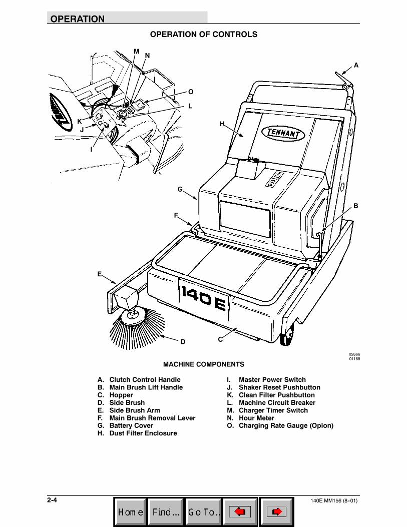
MACHINE COMPONENTS
A. Clutch Control Handle I. Master Power SwitchB. Main Brush Lift Handle J. Shaker Reset PushbuttonC. Hopper K. Clean Filter PushbuttonD. Side Brush L. Machine Circuit BreakerE. Side Brush Arm M. Charger Timer SwitchF. Main Brush Removal Lever N. Hour MeterG. Battery Cover O. Charging Rate Gauge (Opion)H. Dust Filter Enclosure
OPERATION
2-5140E MM156 (8--01)
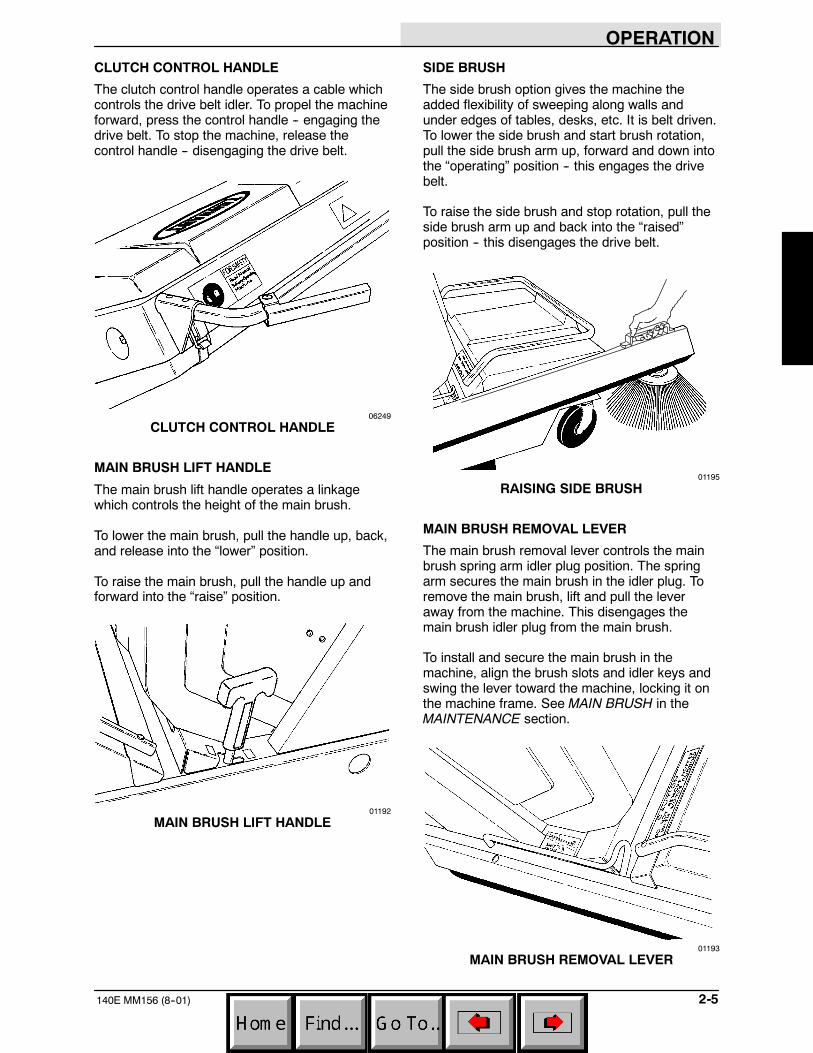
CLUTCH CONTROL HANDLE
The clutch control handle operates a cable whichcontrols the drive belt idler. To propel the machineforward, press the control handle -- engaging thedrive belt. To stop the machine, release thecontrol handle -- disengaging the drive belt.
06249
CLUTCH CONTROL HANDLE
MAIN BRUSH LIFT HANDLE
The main brush lift handle operates a linkagewhich controls the height of the main brush.
To lower the main brush, pull the handle up, back,and release into the “lower” position.
To raise the main brush, pull the handle up andforward into the “raise” position.
01192
MAIN BRUSH LIFT HANDLE
SIDE BRUSH
The side brush option gives the machine theadded flexibility of sweeping along walls andunder edges of tables, desks, etc. It is belt driven.To lower the side brush and start brush rotation,pull the side brush arm up, forward and down intothe “operating” position -- this engages the drivebelt.
To raise the side brush and stop rotation, pull theside brush arm up and back into the “raised”position -- this disengages the drive belt.
01195
RAISING SIDE BRUSH
MAIN BRUSH REMOVAL LEVER
The main brush removal lever controls the mainbrush spring arm idler plug position. The springarm secures the main brush in the idler plug. Toremove the main brush, lift and pull the leveraway from the machine. This disengages themain brush idler plug from the main brush.
To install and secure the main brush in themachine, align the brush slots and idler keys andswing the lever toward the machine, locking it onthe machine frame. See MAIN BRUSH in theMAINTENANCE section.
01193
MAIN BRUSH REMOVAL LEVER
OPERATION
140E MM156 (6--91)2-6
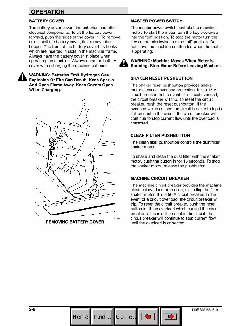
BATTERY COVER
The battery cover covers the batteries and otherelectrical components. To tilt the battery coverforward, push the sides of the cover in. To removeor reinstall the battery cover, first remove thehopper. The front of the battery cover has hookswhich are inserted in slots in the machine frame.Always have the battery cover in place whenoperating the machine. Always open the batterycover when charging the machine batteries.
WARNING: Batteries Emit Hydrogen Gas.Explosion Or Fire Can Result. Keep SparksAnd Open Flame Away. Keep Covers OpenWhen Charging.
01194
REMOVING BATTERY COVER
MASTER POWER SWITCH
The master power switch controls the machinemotor. To start the motor, turn the key clockwiseinto the “on” position. To stop the motor turn thekey counterclockwise into the “off” position. Donot leave the machine unattended when the motoris operating.
WARNING: Machine Moves When Motor IsRunning. Stop Motor Before Leaving Machine.
SHAKER RESET PUSHBUTTON
The shaker reset pushbutton provides shakermotor electrical overload protection. It is a 15 Acircuit breaker. In the event of a circuit overload,the circuit breaker will trip. To reset the circuitbreaker, push the reset pushbutton. If theoverload which caused the circuit breaker to trip isstill present in the circuit, the circuit breaker willcontinue to stop current flow until the overload iscorrected.
CLEAN FILTER PUSHBUTTON
The clean filter pushbutton controls the dust filtershaker motor.
To shake and clean the dust filter with the shakermotor, push the button in for 15 seconds. To stopthe shaker motor, release the pushbutton.
MACHINE CIRCUIT BREAKER
The machine circuit breaker provides the machineelectrical overload protection, excluding the filtershaker motor. It is a 50 A circuit breaker. In theevent of a circuit overload, the circuit breaker willtrip. To reset the circuit breaker, push the resetbutton in. If the overload which caused the circuitbreaker to trip is still present in the circuit, thecircuit breaker will continue to stop current flowuntil the overload is corrected.
OPERATION
2-7140E MM156 (9--92)
CHARGER TIMER SWITCH
The charger timer switch controls the batterycharger on machines below serial number009737. To start the battery charger, open thebattery cover, then plug the battery charger intoan appropriate voltage wall outlet, then turn theswitch knob to the desired number of hours youwish to charge the batteries. The timer willautomatically shut off the charger after the timehas elapsed.
WARNING: Batteries Emit Hydrogen Gas.Explosion Or Fire Can Result. Keep SparksAnd Open Flame Away. Keep Covers OpenWhen Charging.
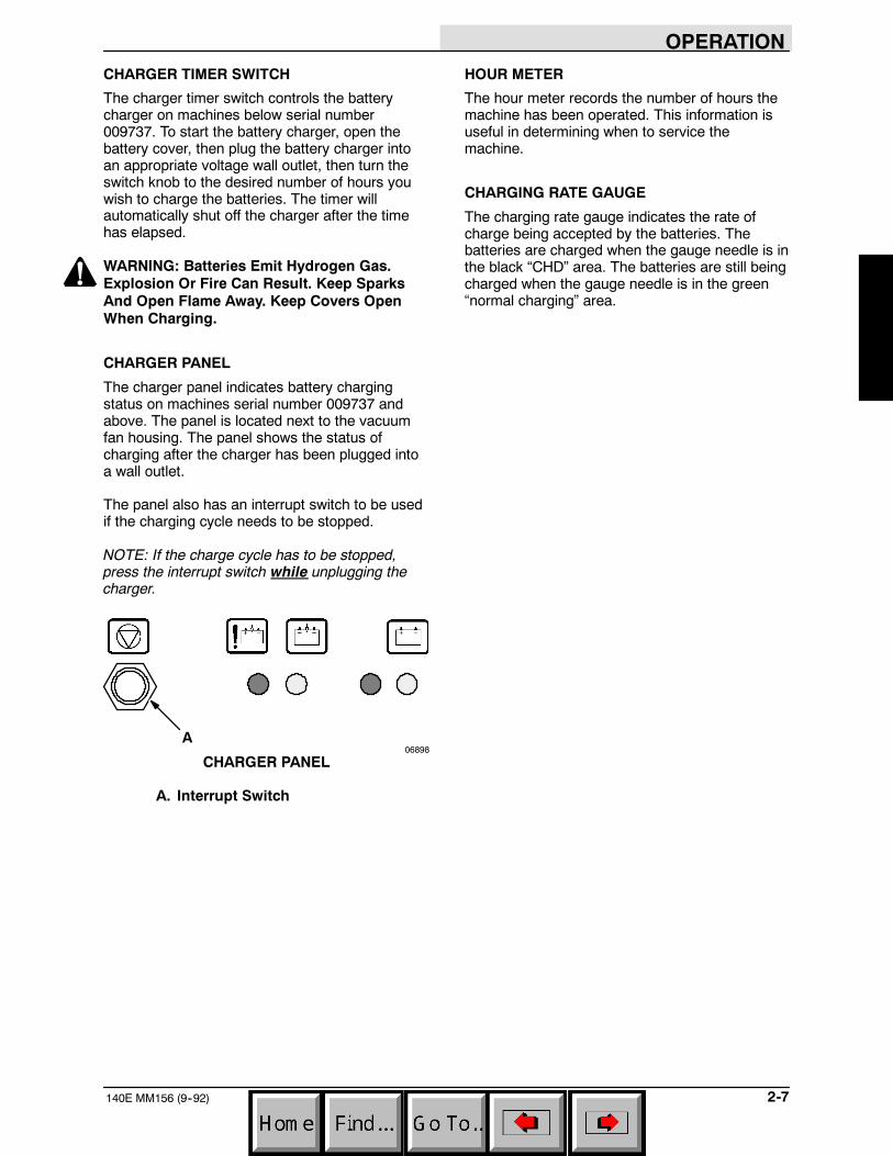
CHARGER PANEL
The charger panel indicates battery chargingstatus on machines serial number 009737 andabove. The panel is located next to the vacuumfan housing. The panel shows the status ofcharging after the charger has been plugged intoa wall outlet.
The panel also has an interrupt switch to be usedif the charging cycle needs to be stopped.
NOTE: If the charge cycle has to be stopped,press the interrupt switch while unplugging thecharger.
A06898
CHARGER PANEL
A. Interrupt Switch
HOUR METER
The hour meter records the number of hours themachine has been operated. This information isuseful in determining when to service themachine.
CHARGING RATE GAUGE
The charging rate gauge indicates the rate ofcharge being accepted by the batteries. Thebatteries are charged when the gauge needle is inthe black “CHD” area. The batteries are still beingcharged when the gauge needle is in the green“normal charging” area.
OPERATION
140E MM156 (6--91)2-8
MACHINE OPERATION
NORMAL SWEEPING OPERATION
A normal sweeping operation consists of seventypical operations: pre-start checklist, startingmachine, sweeping, dumping hopper, postoperation checklist -- motor operating, stoppingmachine, and post operation checklist -- motorstopped.
THE PRE-START CHECKLIST lists things tocheck before starting the machine.
TO START MACHINE lists the steps required tostart the machine.
TO SWEEP lists things to keep in mind beforeand during the sweeping operation.
TO DUMP HOPPER lists the steps required todump the hopper.
POST OPERATION CHECKLIST -- MotorOperating lists things to check before stopping themachine motor.
TO STOP MACHINE lists the steps required tostop the machine.
POST OPERATION CHECKLIST -- MotorStopped lists things to check after stopping themachine motor.
PRE-START CHECKLIST
Check under machine for leak spots.
Check battery charge level.
Check controls for proper operation.
Check service records to determine servicerequirements.
FOR SAFETY: Before Starting Machine, MakeSure All Safety Devices Are In Place AndOperate Properly.
TO START MACHINE
NOTE: Before starting machine, perform thepre-start checks.
1. Place the master power switch in the “on”position.
2. Drive the machine to the area to be cleaned.
TO SWEEP
Plan the sweeping in advance. Try to arrange longruns with minimum stopping and starting. Sweepdebris from very narrow aisles into main aislesahead of time. Do an entire floor or section at onetime. Overlap brush paths.
Pick up oversize debris before sweeping. Flattenor remove bulky cartons from aisles beforesweeping. Pick up pieces of wire, twine, string,etc., which could become entangled in brush orbrush plugs.
Press the clutch handle to place the machine inmotion. Release the clutch handle for easierturning. Sweep as straight a path as possible.Avoid bumping into posts or scraping the sides ofthe sweeper. Empty the debris hopper when itbecomes full.
1. Place the main brush lift handle in the“lower” position.
2. Pull the side brush arm up, forward anddown into the “operating” position if present.
3. Sweep as required.
NOTE: Do not allow the machine to remainstationary with machine operating and the mainbrush in the “lower” position as it may cause wearmarks on the floor.
OPERATION
2-9140E MM156 (6--91)
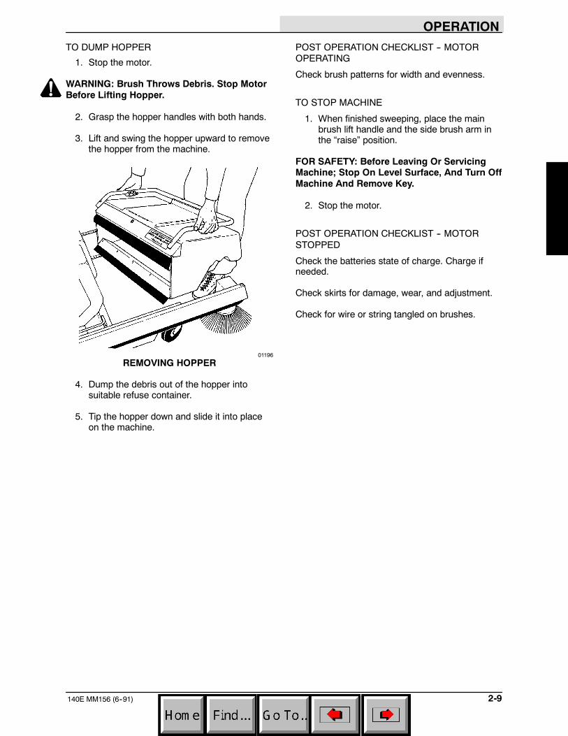
TO DUMP HOPPER
1. Stop the motor.
WARNING: Brush Throws Debris. Stop MotorBefore Lifting Hopper.
2. Grasp the hopper handles with both hands.
3. Lift and swing the hopper upward to removethe hopper from the machine.
01196
REMOVING HOPPER
4. Dump the debris out of the hopper intosuitable refuse container.
5. Tip the hopper down and slide it into placeon the machine.
POST OPERATION CHECKLIST -- MOTOROPERATING
Check brush patterns for width and evenness.
TO STOP MACHINE
1. When finished sweeping, place the mainbrush lift handle and the side brush arm inthe “raise” position.
FOR SAFETY: Before Leaving Or ServicingMachine; Stop On Level Surface, And Turn OffMachine And Remove Key.
2. Stop the motor.
POST OPERATION CHECKLIST -- MOTORSTOPPED
Check the batteries state of charge. Charge ifneeded.
Check skirts for damage, wear, and adjustment.
Check for wire or string tangled on brushes.
OPERATION
140E MM156 (6--91)2-10
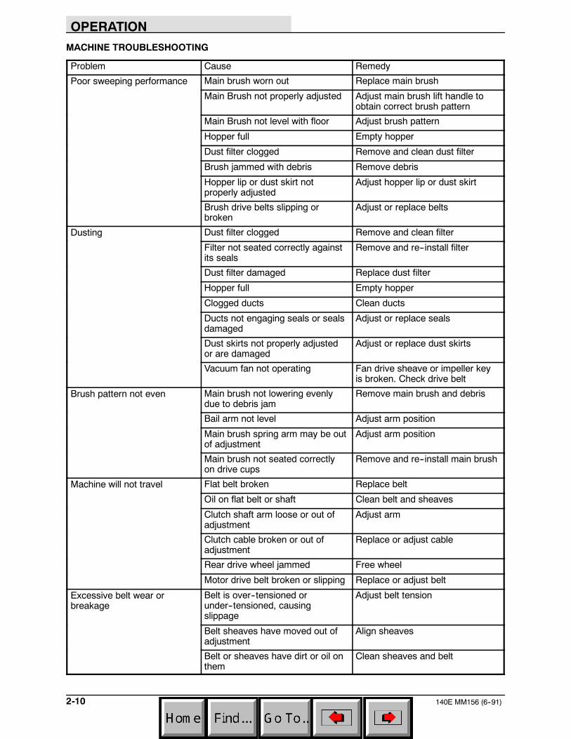
MACHINE TROUBLESHOOTING
Problem Cause Remedy
Poor sweeping performance Main brush worn out Replace main brush
Main Brush not properly adjusted Adjust main brush lift handle toobtain correct brush pattern
Main Brush not level with floor Adjust brush pattern
Hopper full Empty hopper
Dust filter clogged Remove and clean dust filter
Brush jammed with debris Remove debris
Hopper lip or dust skirt notproperly adjusted
Adjust hopper lip or dust skirt
Brush drive belts slipping orbroken
Adjust or replace belts
Dusting Dust filter clogged Remove and clean filter
Filter not seated correctly againstits seals
Remove and re--install filter
Dust filter damaged Replace dust filter
Hopper full Empty hopper
Clogged ducts Clean ducts
Ducts not engaging seals or sealsdamaged
Adjust or replace seals
Dust skirts not properly adjustedor are damaged
Adjust or replace dust skirts
Vacuum fan not operating Fan drive sheave or impeller keyis broken. Check drive belt
Brush pattern not even Main brush not lowering evenlydue to debris jam
Remove main brush and debris
Bail arm not level Adjust arm position
Main brush spring arm may be outof adjustment
Adjust arm position
Main brush not seated correctlyon drive cups
Remove and re--install main brush
Machine will not travel Flat belt broken Replace belt
Oil on flat belt or shaft Clean belt and sheaves
Clutch shaft arm loose or out ofadjustment
Adjust arm
Clutch cable broken or out ofadjustment
Replace or adjust cable
Rear drive wheel jammed Free wheel
Motor drive belt broken or slipping Replace or adjust belt
Excessive belt wear orbreakage
Belt is over--tensioned orunder--tensioned, causingslippage
Adjust belt tension
Belt sheaves have moved out ofadjustment
Align sheaves
Belt or sheaves have dirt or oil onthem
Clean sheaves and belt
OPERATION
2-11140E MM156 (6--91)
MACHINE STORAGE
STORING MACHINE
When storing the machine for extended periods oftime, the following procedures must be followed tolessen the chance of rust, sludge, and otherdeposits from forming:
1. Place the main brush, and side brush if soequipped, in the “raise” position.
2. Empty and clean the debris hopper.
3. Charge the machine batteries.
4. Disconnect the batteries-to-machine batteryconnector.

OPERATION
140E MM156 (6--91)2-12
MAINTENANCE
3-1140E MM156 (3--02)
SECTION 3CONTENTS
PageRECOMMENDED FIRST 20-HOUR
MACHINE INSPECTION 3-3. . . . . . . . . . . . .MAINTENANCE CHART 3-4. . . . . . . . . . . . . . . .ELECTRICAL SYSTEM 3-6. . . . . . . . . . . . . . . . .
BATTERIES 3-6. . . . . . . . . . . . . . . . . . . . . . . .BATTERY CHARGING 3-7. . . . . . . . . . . . . . .
TO CHARGE BATTERIES (For machinesbelow serial number 009737) 3-7. . . .
TO CHARGE BATTERIES (For machinesserial number 009737 and above) 3-8
ELECTRICAL SCHEMATIC (For machinesbelow serial number 009737) 3-10. . . . . . .
ELECTRICAL SCHEMATIC (For machinesserial number 009737 and above) 3-11. . .
BRUSHES 3-12. . . . . . . . . . . . . . . . . . . . . . . . . . . .MAIN BRUSH 3-12. . . . . . . . . . . . . . . . . . . . . . .
TO REMOVE MAIN BRUSH 3-12. . . . . . .TO INSTALL MAIN BRUSH 3-12. . . . . . . .TO CHECK AND ADJUST MAIN
BRUSH PATTERN 3-13. . . . . . . . . . . . .SIDE BRUSH 3-14. . . . . . . . . . . . . . . . . . . . . . .
TO REMOVE SIDE BRUSH 3-14. . . . . . . .TO INSTALL SIDE BRUSH 3-14. . . . . . . .TO ADJUST SIDE BRUSH 3-14. . . . . . . .
DEBRIS HOPPER AND DUST FILTER 3-15. . .DEBRIS HOPPER 3-15. . . . . . . . . . . . . . . . . . .
TO EMPTY HOPPER 3-15. . . . . . . . . . . . .TO ADJUST HOPPER FLOOR
CLEARANCE 3-15. . . . . . . . . . . . . . . . .REAR GUIDE WHEELS 3-16. . . . . . . . . . . . . .
TO ADJUST REAR GUIDE WHEELS 3-16HOPPER DUST FILTER 3-16. . . . . . . . . . . . .
TO REMOVE DUST FILTER 3-17. . . . . . .TO INSTALL DUST FILTER 3-17. . . . . . . .
SKIRTS AND SEALS 3-18. . . . . . . . . . . . . . . . . . .SIDE DUST SKIRTS 3-18. . . . . . . . . . . . . . . . .
TO ADJUST SIDE DUST SKIRTS 3-18. .TO REPLACE SIDE DUST SKIRTS 3-18.
HOPPER SIDE SEALS 3-19. . . . . . . . . . . . . .TO REPLACE HOPPER SIDE
SEALS 3-19. . . . . . . . . . . . . . . . . . . . . . .REAR BRUSH SKIRT 3-19. . . . . . . . . . . . . . . .
TO REPLACE REAR BRUSH SKIRT 3-19
PageBELTS AND CHAINS 3-20. . . . . . . . . . . . . . . . . . .
FLAT PROPELLING BELT 3-20. . . . . . . . . . . .TO CHECK AND ADJUST FLAT
PROPELLING BELT 3-20. . . . . . . . . . .TO REPLACE FLAT PROPELLING
BELT 3-20. . . . . . . . . . . . . . . . . . . . . . . . .MOTOR DRIVE BELT 3-21. . . . . . . . . . . . . . . .
TO CHECK AND ADJUSTMOTOR DRIVE BELT 3-21. . . . . . . . . .
TO REPLACE MOTOR DRIVE BELT 3-22BRUSH DRIVE BELT 3-23. . . . . . . . . . . . . . . .
TO REPLACE BRUSH DRIVE BELT 3-23SIDE BRUSH DRIVE BELT 3-24. . . . . . . . . . .
TO ADJUST SIDE BRUSH DRIVEBELT 3-24. . . . . . . . . . . . . . . . . . . . . . . . .
TO REPLACE SIDE BRUSHDRIVE BELT 3-24. . . . . . . . . . . . . . . . . .
STATIC DRAG CHAIN 3-24. . . . . . . . . . . . . . .PUSHING AND TRANSPORTING THE
MACHINE 3-25. . . . . . . . . . . . . . . . . . . . . . . . . . .PUSHING THE MACHINE 3-25. . . . . . . . . . . .TRANSPORTING THE MACHINE 3-25. . . . .

MAINTENANCE
140E MM156 (3--88)3-2
MAINTENANCE
3-3140E MM156 (3--88)
RECOMMENDED FIRST 20-HOUR MACHINE INSPECTION
After the first 20 hours of operation, perform thefollowing procedures:
1. Check the specific gravity of the batteries.
2. Check the battery cable connections.
3. Check the floor skirts to floor clearance.
4. Check the main brush and side brush, if soequipped, brush patterns.
MAINTENANCE
140E MM156 (7--90)3-4
MAINTENANCE CHART
1
2
3
4
56
78
910
11
12
4
37
8
01189
MAINTENANCE
3-5140E MM156 (12--96)
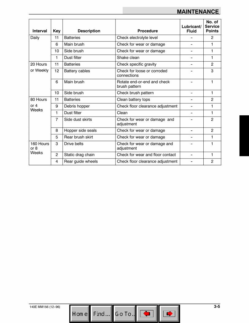
Interval Key Description ProcedureLubricant/
Fluid
No. ofServicePoints
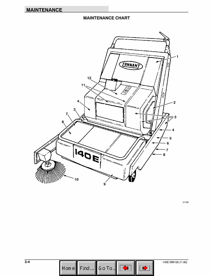
Daily 11 Batteries Check electrolyte level -- 2
6 Main brush Check for wear or damage -- 1
10 Side brush Check for wear or damage -- 1
1 Dust filter Shake clean -- 1
20 Hours 11 Batteries Check specific gravity -- 2
or Weekly 12 Battery cables Check for loose or corrodedconnections
-- 3
6 Main brush Rotate end-or-end and checkbrush pattern
-- 1
10 Side brush Check brush pattern -- 1
80 Hours 11 Batteries Clean battery tops -- 2
or 4Weeks
9 Debris hopper Check floor clearance adjustment -- 1Weeks
1 Dust filter Clean -- 1
7 Side dust skirts Check for wear or damage andadjustment
-- 2
8 Hopper side seals Check for wear or damage -- 2
5 Rear brush skirt Check for wear or damage -- 1
160 Hoursor 8W k
3 Drive belts Check for wear or damage andadjustment
-- 1
Weeks 2 Static drag chain Check for wear and floor contact -- 1
4 Rear guide wheels Check floor clearance adjustment -- 2
MAINTENANCE
140E MM156 (12--00)3-6
ELECTRICAL SYSTEM
BATTERIES
The two 12-volt machine batteries provide all ofthe energy used by the machine. The standardbatteries are rated at 530 CCA. They requireregular maintenance to keep them operating theirbest.
Do not allow batteries to remain in dischargedcondition for any length of time. Do not operatemachine if batteries are in poor condition ordischarged beyond 75%, specific gravity below1.170.
Check the battery cables for loose connections onthe battery terminals daily. Inspect the cables forcorrosion or damage.
Clean the top surface and the terminals of thebatteries after every 80 hours of operation. Use astrong solution of baking soda and water. Brushthe solution sparingly over the battery top,terminals, and cable clamps. Do not allow anybaking soda solution to enter the battery. Use awire brush to clean the terminal posts and thecable connectors. After cleaning, apply a coatingof clear petroleum jelly to the terminals and thecable connectors. Keep the tops of the batteriesclean and dry.
Keep all metallic objects off the top of thebatteries, as they may cause a short circuit.Replace worn or damaged wires.
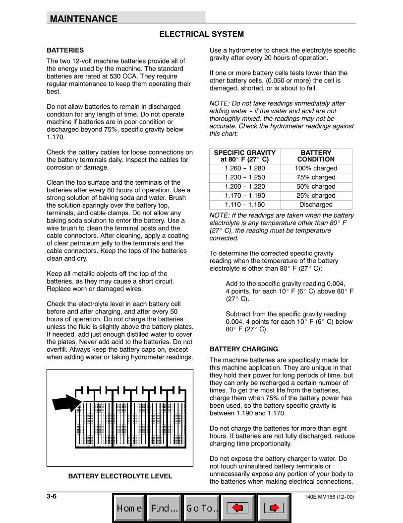
Check the electrolyte level in each battery cellbefore and after charging, and after every 50hours of operation. Do not charge the batteriesunless the fluid is slightly above the battery plates.If needed, add just enough distilled water to coverthe plates. Never add acid to the batteries. Do notoverfill. Always keep the battery caps on, exceptwhen adding water or taking hydrometer readings.
BATTERY ELECTROLYTE LEVEL
Use a hydrometer to check the electrolyte specificgravity after every 20 hours of operation.
If one or more battery cells tests lower than theother battery cells, (0.050 or more) the cell isdamaged, shorted, or is about to fail.
NOTE: Do not take readings immediately afteradding water -- if the water and acid are notthoroughly mixed, the readings may not beaccurate. Check the hydrometer readings againstthis chart:
SPECIFIC GRAVITYat 80_ F (27_ C)
BATTERYCONDITION
1.260 -- 1.280 100% charged1.230 -- 1.250 75% charged1.200 -- 1.220 50% charged1.170 -- 1.190 25% charged1.110 -- 1.160 Discharged
NOTE: If the readings are taken when the batteryelectrolyte is any temperature other than 80_ F(27_ C), the reading must be temperaturecorrected.
To determine the corrected specific gravityreading when the temperature of the batteryelectrolyte is other than 80_ F (27_ C):
Add to the specific gravity reading 0.004,4 points, for each 10_ F (6_ C) above 80_ F(27_ C).
Subtract from the specific gravity reading0.004, 4 points for each 10_ F (6_ C) below80_ F (27_ C).
BATTERY CHARGING
The machine batteries are specifically made forthis machine application. They are unique in thatthey hold their power for long periods of time, butthey can only be recharged a certain number oftimes. To get the most life from the batteries,charge them when 75% of the battery power hasbeen used, so the battery specific gravity isbetween 1.190 and 1.170.
Do not charge the batteries for more than eighthours. If batteries are not fully discharged, reducecharging time proportionally.
Do not expose the battery charger to water. Donot touch uninsulated battery terminals orunnecessarily expose any portion of your body tothe batteries when making electrical connections.
MAINTENANCE
3-7140E MM156 (3--02)
TO CHARGE BATTERIES (For machines belowserial number 009737)
1. Stop the machine on a flat, dry surface nextto an electrical outlet.
2. Turn off the master power switch.
FOR SAFETY: Before Leaving Or ServicingMachine; Stop On Level Surface, And Turn OffMachine And Remove Key.
3. Lift the battery cover into the “open”position.
WARNING: Batteries Emit Hydrogen Gas.Explosion Or Fire Can Result. Keep SparksAnd Open Flame Away. Keep Covers OpenWhen Charging.
4. Check the water level in the batteries.
08247
CHECK ELECTROLYTE LEVEL
If the water level is low, add just enough distilledwater to cover the plates. DO NOT OVERFILL.The battery can overflow during charging due toexpansion.
BATTERY ELECTROLYTE LEVEL
NOTE: Make sure the battery caps are in placewhile charging.
FOR SAFETY: When Servicing Machine, AvoidContact With Battery Acid.
5. Turn the battery charger timer to the “off”position.
6. Plug the battery charger into an electricaloutlet.
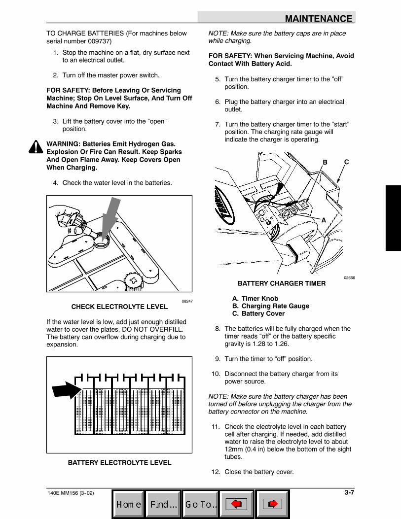
7. Turn the battery charger timer to the “start”position. The charging rate gauge willindicate the charger is operating.
A
B C
02666
BATTERY CHARGER TIMER
A. Timer KnobB. Charging Rate GaugeC. Battery Cover
8. The batteries will be fully charged when thetimer reads “off” or the battery specificgravity is 1.28 to 1.26.
9. Turn the timer to “off” position.
10. Disconnect the battery charger from itspower source.
NOTE: Make sure the battery charger has beenturned off before unplugging the charger from thebattery connector on the machine.
11. Check the electrolyte level in each batterycell after charging. If needed, add distilledwater to raise the electrolyte level to about12mm (0.4 in) below the bottom of the sighttubes.
12. Close the battery cover.
MAINTENANCE
140E MM156 (12--00)3-8
TO CHARGE BATTERIES (For machines serialnumber 009737 and above)
1. Stop the machine on a flat, dry surface nextto an electrical outlet.
2. Turn off the master power switch.
FOR SAFETY: Before Leaving Or ServicingMachine; Stop On Level Surface, And Turn OffMachine And Remove Key.
3. Lift the battery cover into the “open”position.
WARNING: Batteries Emit Hydrogen Gas.Explosion Or Fire Can Result. Keep SparksAnd Open Flame Away. Keep Covers OpenWhen Charging.
4. Check the water level in the batteries.
08247
CHECK ELECTROLYTE LEVEL
If the water level is low, add just enough distilledwater to cover the plates. DO NOT OVERFILL.The battery can overflow during charging due toexpansion.
BATTERY ELECTROLYTE LEVEL
FOR SAFETY: When Servicing Machine, AvoidContact With Battery Acid.
5. Plug the battery charger into an AC walloutlet. The charger will go through a selfdiagnostic check. All the indicator lamps onthe charger panel will flash showing thediagnostic check is in progress.
NOTE: If the red no charge indicator lamp lightswhen the charger is plugged into a wall outlet, thecharger can not charge the battery, meaning thereis something wrong with the battery.
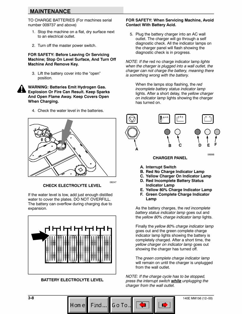
When the lamps stop flashing, the redincomplete battery status indicator lamplights. After a short delay, the yellow chargeron indicator lamp lights showing the chargerhas turned on.
AB C D E F
06898
CHARGER PANEL
A. Interrupt SwitchB. Red No Charge Indicator LampC. Yellow Charger On Indicator LampD. Red Incomplete Battery Status
Indicator LampE. Yellow 80% Charge Indicator LampF. Green Complete Charge Indicator
Lamp
As the battery charges, the red incompletebattery status indicator lamp goes out andthe yellow 80% charge indicator lamp lights.
Finally the yellow 80% charge indicator lampgoes out and the green complete chargeindicator lamp lights showing the battery iscompletely charged. After a short time, theyellow charger on indicator lamp goes outshowing the charger has turned off.
The green complete charge indicator lampwill remain on until the charger is unpluggedfrom the wall outlet.
NOTE: If the charge cycle has to be stopped,press the interrupt switch while unplugging thecharger from the wall outlet.
MAINTENANCE
3-9140E MM156 (6--03)
6. Unplug the charger from the wall outlet.
7. Check the electrolyte level in each batterycell after charging. If needed, add distilledwater to raise the electrolyte level to about12mm (0.4 in) below the bottom of the sighttubes.
8. Close the battery cover.
MAINTENANCE
140E MM156 (6--91)3-10
12 VBATTERY
12 VBATTERY
DRIVE MOTOR
AMMETER SHAKERSHAKER MOTOR
CHARGER (50HZ)
CHARGER (60HZ)TIMER
SWITCH
KEYSWITCH
15/BLK
12/WHT
14/BLK
BLK
WHT
11/RED
7/RED
8/RED
RED
24/BLK 2/BLK
20/YEL 21/BLK
9/BLK
26/BLK
27/ORA
18/BLU
BLK
BLK
28/ORA17/BLU
13/BLK
BLK
CB---2
15AM1
HMA
M116/BLK
PMTL
C
A.C.Voltage
JumperConnection
100 VAC
115 VAC
230 VAC(Double)
RED
BLK
Timer T
WHTCommon
Line L
Internal Terminal
BLK
BLK1234
56
7856
A
B
CD
S
F
Cap
10/RED
1 to 52 to 61 to 43 to 63 to 43 to 4
DCCord
02649
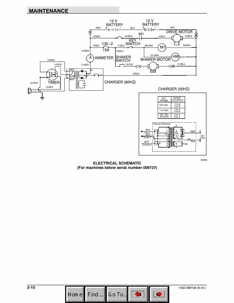
ELECTRICAL SCHEMATIC(For machines below serial number 009737)
MAINTENANCE
3-11140E MM156 (6--91)
06985
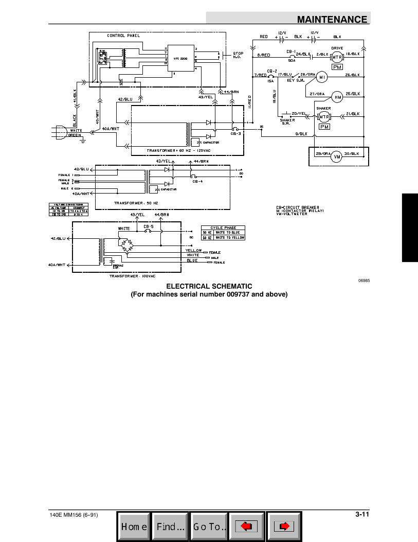
ELECTRICAL SCHEMATIC(For machines serial number 009737 and above)
MAINTENANCE
140E MM156 (12--95)3-12
BRUSHES
MAIN BRUSH
The main brush is tubular and spans the width ofthe machine. It sweeps debris into the hopper. Itshould be inspected daily for wear or damage.Remove any string or wire found tangled on themain brush, main brush drive hub, or main brushidler hub.
The main brush pattern should be checked afterevery 20 hours of operation. The main brushpattern should be approximately 1.5 in (40 mm)wide when sweeping hard floors and 0.5 in(15 mm) when sweeping carpeted floors. Checkthe main brush pattern only on hard floors with themain brush in the lowered position. Main brushpattern adjustments are made by rotating themain brush lift handle. Use the carpet brush oncarpets for better performance and brush life.
Rotate the brush after every 20 hours of operationfor maximum brush life. The main brush should bereplaced when the remaining brush bristlemeasures 1.25 in (30 mm).
TO REMOVE MAIN BRUSH
1. Place the master power switch in the “off”position.
FOR SAFETY: Before Leaving Or ServicingMachine; Stop On Level Surface, And Turn OffMachine And Remove Key.
2. Disconnect the batteries-to-machineconnector.
3. Lift the hopper up and out of the machine.
WARNING: Brush Throws Debris. Stop MotorBefore Lifting Hopper.
4. Pull the main brush removal lever away fromthe machine to disengage the main brushidler plug from the main brush.
5. Grasp the main brush and pull it off the mainbrush drive plug and out of the main brushcompartment.
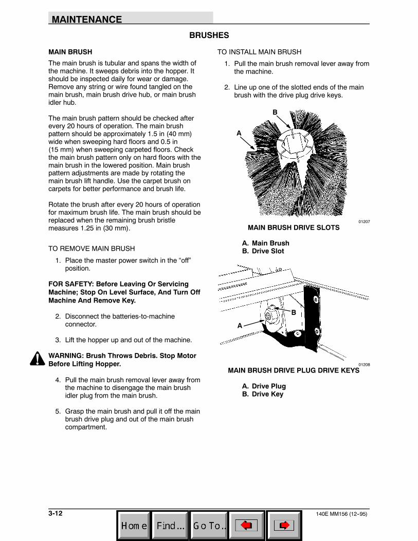
TO INSTALL MAIN BRUSH
1. Pull the main brush removal lever away fromthe machine.
2. Line up one of the slotted ends of the mainbrush with the drive plug drive keys.
A
B
01207
MAIN BRUSH DRIVE SLOTS
A. Main BrushB. Drive Slot
A
B
01208
MAIN BRUSH DRIVE PLUG DRIVE KEYS
A. Drive PlugB. Drive Key
MAINTENANCE
3-13140E MM156 (3--94)
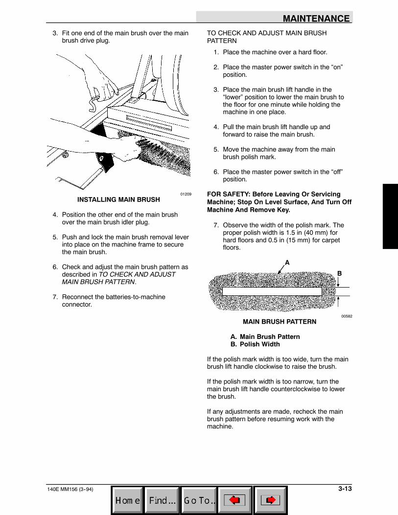
3. Fit one end of the main brush over the mainbrush drive plug.
01209
INSTALLING MAIN BRUSH
4. Position the other end of the main brushover the main brush idler plug.
5. Push and lock the main brush removal leverinto place on the machine frame to securethe main brush.
6. Check and adjust the main brush pattern asdescribed in TO CHECK AND ADJUSTMAIN BRUSH PATTERN.
7. Reconnect the batteries-to-machineconnector.
TO CHECK AND ADJUST MAIN BRUSHPATTERN
1. Place the machine over a hard floor.
2. Place the master power switch in the “on”position.
3. Place the main brush lift handle in the“lower” position to lower the main brush tothe floor for one minute while holding themachine in one place.
4. Pull the main brush lift handle up andforward to raise the main brush.
5. Move the machine away from the mainbrush polish mark.
6. Place the master power switch in the “off”position.
FOR SAFETY: Before Leaving Or ServicingMachine; Stop On Level Surface, And Turn OffMachine And Remove Key.
7. Observe the width of the polish mark. Theproper polish width is 1.5 in (40 mm) forhard floors and 0.5 in (15 mm) for carpetfloors.
A
B
00582
MAIN BRUSH PATTERN
A. Main Brush PatternB. Polish Width
If the polish mark width is too wide, turn the mainbrush lift handle clockwise to raise the brush.
If the polish mark width is too narrow, turn themain brush lift handle counterclockwise to lowerthe brush.
If any adjustments are made, recheck the mainbrush pattern before resuming work with themachine.
MAINTENANCE
140E MM156 (6--91)3-14
SIDE BRUSH
The side brush sweeps debris from walls or curbsinto the path of the main brush. It should beinspected daily for wear or damage. Remove anystring or wire found tangled on the side brush orside brush drive hub.
The side brush adjustment should be checkedafter every 20 hours of operation. The side brushis properly adjusted when, with the side brush armin the “raised” position, there is approximately1 in (25 mm) of space between the floor and theside brush bristles.
Side brush adjustments are made by mountingthe side brush in a different one of the fivemounting holes in the side brush drive shaft.
The side brush should be replaced when theremaining brush bristle measures 1 in (25 mm) inlength.
TO REMOVE SIDE BRUSH
1. Place the master power switch in the “off”position.
FOR SAFETY: Before Leaving Or ServicingMachine; Stop On Level Surface, And Turn OffMachine And Remove Key.
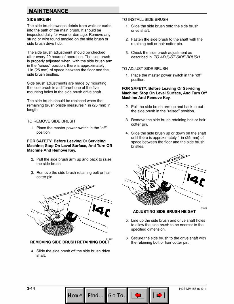
2. Pull the side brush arm up and back to raisethe side brush.
3. Remove the side brush retaining bolt or haircotter pin.
01027
REMOVING SIDE BRUSH RETAINING BOLT
4. Slide the side brush off the side brush driveshaft.
TO INSTALL SIDE BRUSH
1. Slide the side brush onto the side brushdrive shaft.
2. Fasten the side brush to the shaft with theretaining bolt or hair cotter pin.
3. Check the side brush adjustment asdescribed in TO ADJUST SIDE BRUSH.
TO ADJUST SIDE BRUSH
1. Place the master power switch in the “off”position.
FOR SAFETY: Before Leaving Or ServicingMachine; Stop On Level Surface, And Turn OffMachine And Remove Key.
2. Pull the side brush arm up and back to putthe side brush in the “raised” position.
3. Remove the side brush retaining bolt or haircotter pin.
4. Slide the side brush up or down on the shaftuntil there is approximately 1 in (25 mm) ofspace between the floor and the side brushbristles.
01027
ADJUSTING SIDE BRUSH HEIGHT
5. Line up the side brush and drive shaft holesto allow the side brush to be nearest to thespecified dimension.
6. Secure the side brush to the drive shaft withthe retaining bolt or hair cotter pin.
MAINTENANCE
3-15140E MM156 (6--91)
DEBRIS HOPPER AND DUST FILTER
DEBRIS HOPPER
The debris hopper collects debris swept up by themain brush. It should be emptied after every workshift.
The hopper floor clearance should be checkedand adjusted, if necessary, after every 80 hours ofoperation.
TO EMPTY HOPPER
1. Place the master power switch in the “off”position.
WARNING: Brush Throws Debris. Stop MotorBefore Lifting Hopper.
2. Grasp the hopper handles with both hands.
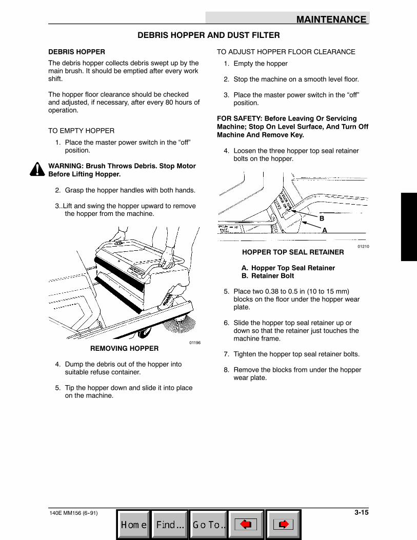
3..Lift and swing the hopper upward to removethe hopper from the machine.
01196
REMOVING HOPPER
4. Dump the debris out of the hopper intosuitable refuse container.
5. Tip the hopper down and slide it into placeon the machine.
TO ADJUST HOPPER FLOOR CLEARANCE
1. Empty the hopper
2. Stop the machine on a smooth level floor.
3. Place the master power switch in the “off”position.
FOR SAFETY: Before Leaving Or ServicingMachine; Stop On Level Surface, And Turn OffMachine And Remove Key.
4. Loosen the three hopper top seal retainerbolts on the hopper.
B
A
01210
HOPPER TOP SEAL RETAINER
A. Hopper Top Seal RetainerB. Retainer Bolt
5. Place two 0.38 to 0.5 in (10 to 15 mm)blocks on the floor under the hopper wearplate.
6. Slide the hopper top seal retainer up ordown so that the retainer just touches themachine frame.
7. Tighten the hopper top seal retainer bolts.
8. Remove the blocks from under the hopperwear plate.
MAINTENANCE
140E MM156 (6--91)3-16
REAR GUIDE WHEELS
The rear guide wheels prevent the rear of themachine from tipping. They are located justbehind the main brush shroud. Check the floorclearance after every 160 hours of operation.They should clear the floor by 0.38 in (10 mm).
TO ADJUST REAR GUIDE WHEELS
1. Place the master power switch in the “off”position.
FOR SAFETY: Before Leaving Or ServicingMachine; Stop On Level Surface, And Turn OffMachine And Remove Key.
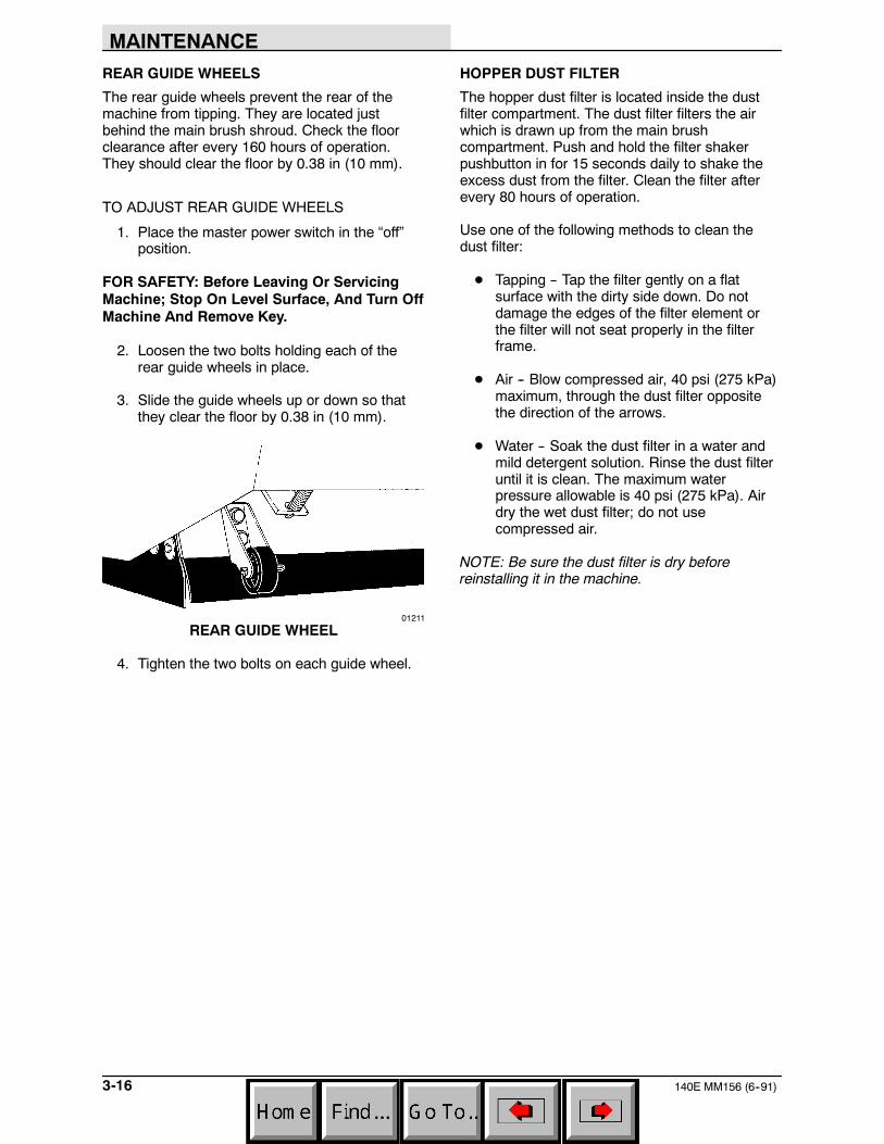
2. Loosen the two bolts holding each of therear guide wheels in place.
3. Slide the guide wheels up or down so thatthey clear the floor by 0.38 in (10 mm).
01211
REAR GUIDE WHEEL
4. Tighten the two bolts on each guide wheel.
HOPPER DUST FILTER
The hopper dust filter is located inside the dustfilter compartment. The dust filter filters the airwhich is drawn up from the main brushcompartment. Push and hold the filter shakerpushbutton in for 15 seconds daily to shake theexcess dust from the filter. Clean the filter afterevery 80 hours of operation.
Use one of the following methods to clean thedust filter:
D Tapping -- Tap the filter gently on a flatsurface with the dirty side down. Do notdamage the edges of the filter element orthe filter will not seat properly in the filterframe.
D Air -- Blow compressed air, 40 psi (275 kPa)maximum, through the dust filter oppositethe direction of the arrows.
D Water -- Soak the dust filter in a water andmild detergent solution. Rinse the dust filteruntil it is clean. The maximum waterpressure allowable is 40 psi (275 kPa). Airdry the wet dust filter; do not usecompressed air.
NOTE: Be sure the dust filter is dry beforereinstalling it in the machine.
MAINTENANCE
3-17140E MM156 (6--91)
TO REMOVE DUST FILTER
1. Place the master power switch in the “off”position.
FOR SAFETY: Before Leaving Or ServicingMachine; Stop On Level Surface, And Turn OffMachine And Remove Key.
2. Push the filter shaker pushbutton to shakethe excess dust from the dust filter.
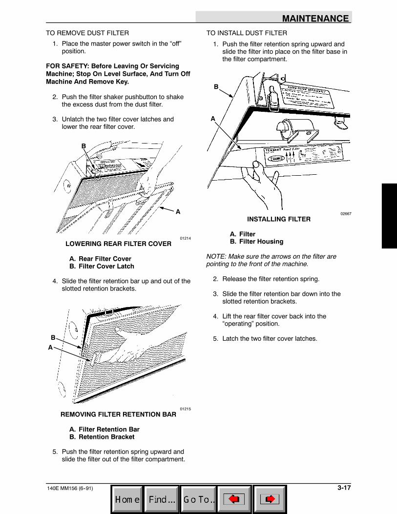
3. Unlatch the two filter cover latches andlower the rear filter cover.
A
B
01214
LOWERING REAR FILTER COVER
A. Rear Filter CoverB. Filter Cover Latch
4. Slide the filter retention bar up and out of theslotted retention brackets.
B
A
01215
REMOVING FILTER RETENTION BAR
A. Filter Retention BarB. Retention Bracket
5. Push the filter retention spring upward andslide the filter out of the filter compartment.
TO INSTALL DUST FILTER
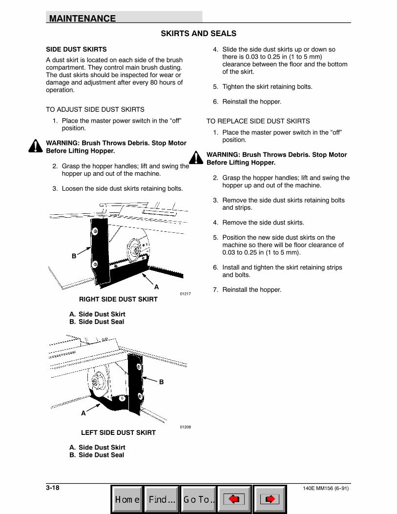
1. Push the filter retention spring upward andslide the filter into place on the filter base inthe filter compartment.
B
A
02667
INSTALLING FILTER
A. FilterB. Filter Housing
NOTE: Make sure the arrows on the filter arepointing to the front of the machine.
2. Release the filter retention spring.
3. Slide the filter retention bar down into theslotted retention brackets.
4. Lift the rear filter cover back into the“operating” position.
5. Latch the two filter cover latches.
MAINTENANCE
140E MM156 (6--91)3-18
SKIRTS AND SEALS
SIDE DUST SKIRTS
A dust skirt is located on each side of the brushcompartment. They control main brush dusting.The dust skirts should be inspected for wear ordamage and adjustment after every 80 hours ofoperation.
TO ADJUST SIDE DUST SKIRTS
1. Place the master power switch in the “off”position.
WARNING: Brush Throws Debris. Stop MotorBefore Lifting Hopper.
2. Grasp the hopper handles; lift and swing thehopper up and out of the machine.
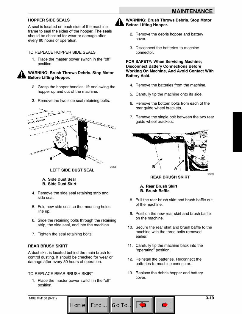
3. Loosen the side dust skirts retaining bolts.
B
A01217
RIGHT SIDE DUST SKIRT
A. Side Dust SkirtB. Side Dust Seal
B
A
01208
LEFT SIDE DUST SKIRT
A. Side Dust SkirtB. Side Dust Seal
4. Slide the side dust skirts up or down sothere is 0.03 to 0.25 in (1 to 5 mm)clearance between the floor and the bottomof the skirt.
5. Tighten the skirt retaining bolts.
6. Reinstall the hopper.
TO REPLACE SIDE DUST SKIRTS
1. Place the master power switch in the “off”position.
WARNING: Brush Throws Debris. Stop MotorBefore Lifting Hopper.
2. Grasp the hopper handles; lift and swing thehopper up and out of the machine.
3. Remove the side dust skirts retaining boltsand strips.
4. Remove the side dust skirts.
5. Position the new side dust skirts on themachine so there will be floor clearance of0.03 to 0.25 in (1 to 5 mm).
6. Install and tighten the skirt retaining stripsand bolts.
7. Reinstall the hopper.
MAINTENANCE
3-19140E MM156 (6--91)
HOPPER SIDE SEALS
A seal is located on each side of the machineframe to seal the sides of the hopper. The sealsshould be checked for wear or damage afterevery 80 hours of operation.
TO REPLACE HOPPER SIDE SEALS
1. Place the master power switch in the “off”position.
WARNING: Brush Throws Debris. Stop MotorBefore Lifting Hopper.
2. Grasp the hopper handles; lift and swing thehopper up and out of the machine.
3. Remove the two side seal retaining bolts.
A
B
01208
LEFT SIDE DUST SEAL
A. Side Dust SealB. Side Dust Skirt
4. Remove the side seal retaining strip andside seal.
5. Fold new side seal so the mounting holesline up.
6. Slide the retaining bolts through the retainingstrip, the side seal, and into the machine.
7. Tighten the seal retaining bolts.
REAR BRUSH SKIRT
A dust skirt is located behind the main brush tocontrol dusting. It should be checked for wear ordamage after every 80 hours of operation.
TO REPLACE REAR BRUSH SKIRT
1. Place the master power switch in the “off”position.
WARNING: Brush Throws Debris. Stop MotorBefore Lifting Hopper.
2. Remove the debris hopper and batterycover.
3. Disconnect the batteries-to-machineconnector.
FOR SAFETY: When Servicing Machine;Disconnect Battery Connections BeforeWorking On Machine, And Avoid Contact WithBattery Acid.
4. Remove the batteries from the machine.
5. Carefully tip the machine onto its side.
6. Remove the bottom bolts from each of therear guide wheel brackets.
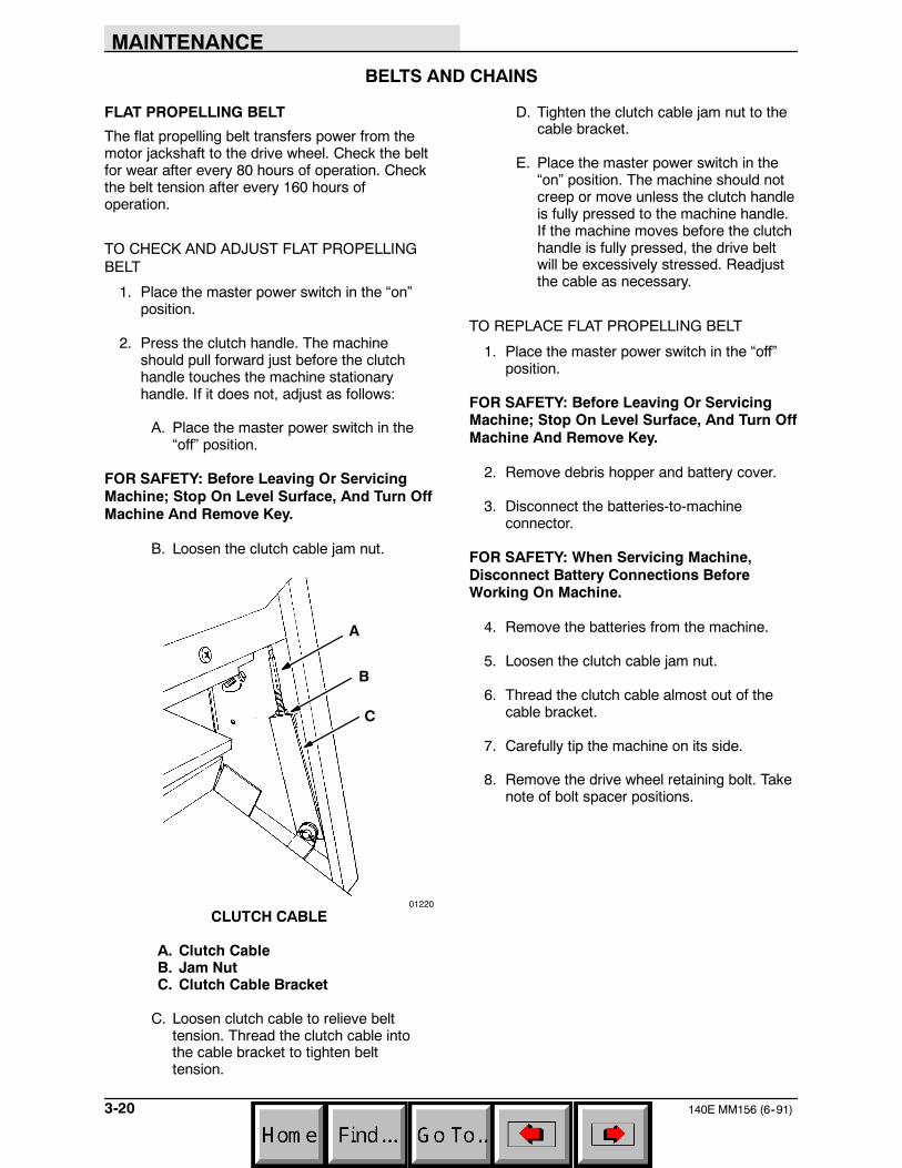
7. Remove the single bolt between the two rearguide wheel brackets.
AB
01218
REAR BRUSH SKIRT
A. Rear Brush SkirtB. Brush Baffle
8. Pull the rear brush skirt and brush baffle outof the machine.
9. Position the new rear skirt and brush baffleon the machine.
10. Secure the rear skirt and brush baffle to themachine with the three bolts removedearlier.
11. Carefully tip the machine back into the“operating” position.
12. Reinstall the batteries. Reconnect thebatteries-to-machine connector.
13. Replace the debris hopper and batterycover.
MAINTENANCE
140E MM156 (6--91)3-20
BELTS AND CHAINS
FLAT PROPELLING BELT
The flat propelling belt transfers power from themotor jackshaft to the drive wheel. Check the beltfor wear after every 80 hours of operation. Checkthe belt tension after every 160 hours ofoperation.
TO CHECK AND ADJUST FLAT PROPELLINGBELT
1. Place the master power switch in the “on”position.
2. Press the clutch handle. The machineshould pull forward just before the clutchhandle touches the machine stationaryhandle. If it does not, adjust as follows:
A. Place the master power switch in the“off” position.
FOR SAFETY: Before Leaving Or ServicingMachine; Stop On Level Surface, And Turn OffMachine And Remove Key.
B. Loosen the clutch cable jam nut.
A
B
C
01220
CLUTCH CABLE
A. Clutch CableB. Jam NutC. Clutch Cable Bracket
C. Loosen clutch cable to relieve belttension. Thread the clutch cable intothe cable bracket to tighten belttension.
D. Tighten the clutch cable jam nut to thecable bracket.
E. Place the master power switch in the“on” position. The machine should notcreep or move unless the clutch handleis fully pressed to the machine handle.If the machine moves before the clutchhandle is fully pressed, the drive beltwill be excessively stressed. Readjustthe cable as necessary.
TO REPLACE FLAT PROPELLING BELT
1. Place the master power switch in the “off”position.
FOR SAFETY: Before Leaving Or ServicingMachine; Stop On Level Surface, And Turn OffMachine And Remove Key.
2. Remove debris hopper and battery cover.
3. Disconnect the batteries-to-machineconnector.
FOR SAFETY: When Servicing Machine,Disconnect Battery Connections BeforeWorking On Machine.
4. Remove the batteries from the machine.
5. Loosen the clutch cable jam nut.
6. Thread the clutch cable almost out of thecable bracket.
7. Carefully tip the machine on its side.
8. Remove the drive wheel retaining bolt. Takenote of bolt spacer positions.
MAINTENANCE
3-21140E MM156 (6--91)
A
B
CD
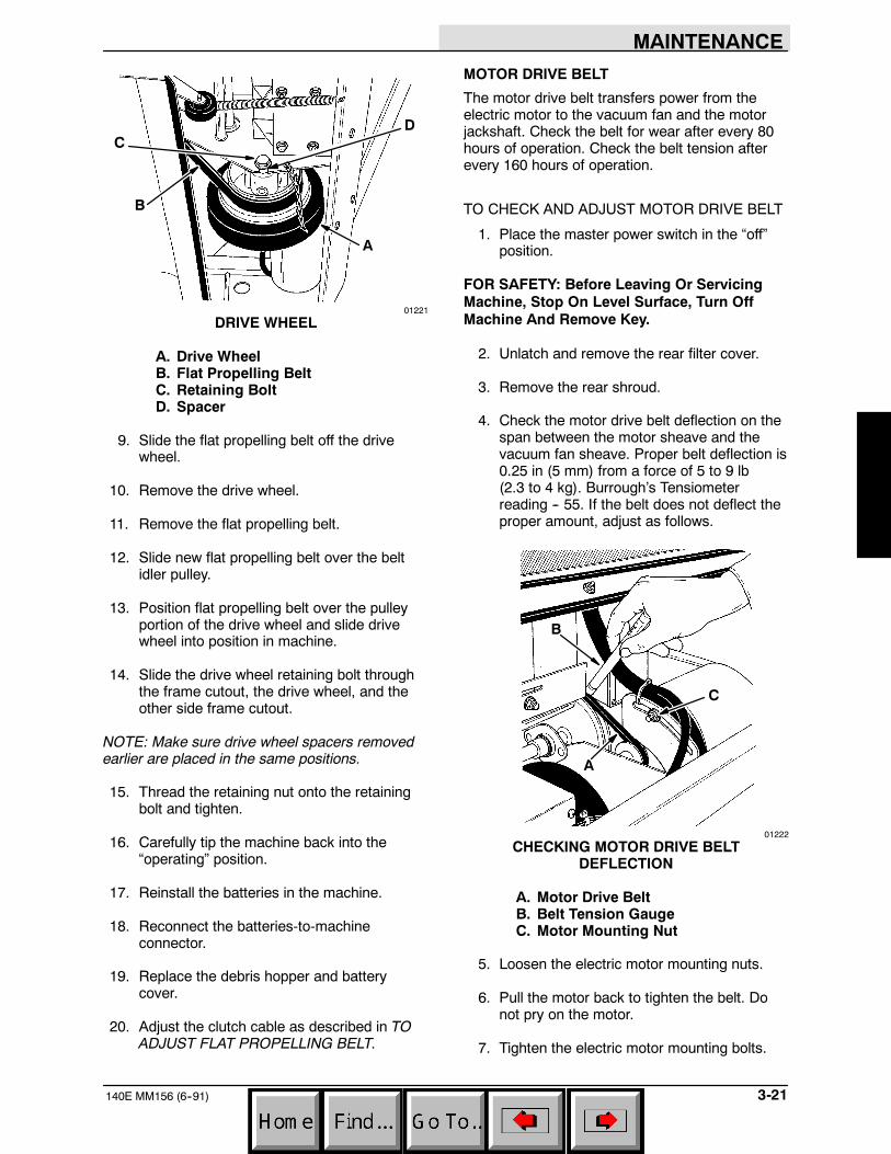
01221
DRIVE WHEEL
A. Drive WheelB. Flat Propelling BeltC. Retaining BoltD. Spacer
9. Slide the flat propelling belt off the drivewheel.
10. Remove the drive wheel.
11. Remove the flat propelling belt.
12. Slide new flat propelling belt over the beltidler pulley.
13. Position flat propelling belt over the pulleyportion of the drive wheel and slide drivewheel into position in machine.
14. Slide the drive wheel retaining bolt throughthe frame cutout, the drive wheel, and theother side frame cutout.
NOTE: Make sure drive wheel spacers removedearlier are placed in the same positions.
15. Thread the retaining nut onto the retainingbolt and tighten.
16. Carefully tip the machine back into the“operating” position.
17. Reinstall the batteries in the machine.
18. Reconnect the batteries-to-machineconnector.
19. Replace the debris hopper and batterycover.
20. Adjust the clutch cable as described in TOADJUST FLAT PROPELLING BELT.
MOTOR DRIVE BELT
The motor drive belt transfers power from theelectric motor to the vacuum fan and the motorjackshaft. Check the belt for wear after every 80hours of operation. Check the belt tension afterevery 160 hours of operation.
TO CHECK AND ADJUST MOTOR DRIVE BELT
1. Place the master power switch in the “off”position.
FOR SAFETY: Before Leaving Or ServicingMachine, Stop On Level Surface, Turn OffMachine And Remove Key.
2. Unlatch and remove the rear filter cover.
3. Remove the rear shroud.
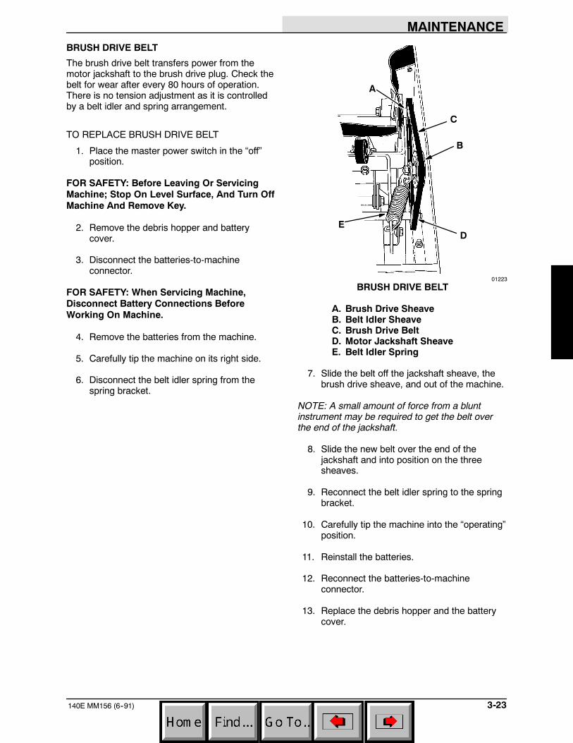
4. Check the motor drive belt deflection on thespan between the motor sheave and thevacuum fan sheave. Proper belt deflection is0.25 in (5 mm) from a force of 5 to 9 lb(2.3 to 4 kg). Burrough’s Tensiometerreading -- 55. If the belt does not deflect theproper amount, adjust as follows.
A
B
C
01222
CHECKING MOTOR DRIVE BELTDEFLECTION
A. Motor Drive BeltB. Belt Tension GaugeC. Motor Mounting Nut
5. Loosen the electric motor mounting nuts.
6. Pull the motor back to tighten the belt. Donot pry on the motor.
7. Tighten the electric motor mounting bolts.

MAINTENANCE
140E MM156 (6--91)3-22
8. Recheck the belt tension, readjust asnecessary.
9. Reinstall the rear shroud and rear filtercover.
TO REPLACE MOTOR DRIVE BELT
1. Place the master power switch in the “off”position.
FOR SAFETY: Before Leaving Or ServicingMachine; Stop On Level Surface, And Turn OffMachine And Remove Key.
2. Unlatch and remove the rear filter cover.
3. Remove the rear shroud and battery cover.
4. Loosen the electric motor mounting nuts.
5. Pivot motor forward to loosen the existingdrive belt.
NOTE: For machines equipped with a side brush:
A. Loosen the locking collar setscrew.
01204
LOOSENING LOCKING COLLAR SETSCREW
B. Unthread and separate the jackshaftextension from the jackshaft enough toslide the drive belt through. Also notethat the jackshaft extension is threadedonto the jackshaft with left handthreads.
6. Remove existing drive belt.
7. Position new drive belt over vacuum fansheave, large diameter sheave, and motorsheave.
NOTE: For machines equipped with a side brush:
A. Reconnect and tighten the jackshaftextension to the jackshaft. Rememberthe jackshaft extension is threaded ontothe jackshaft with left hand threads.
B. Reposition the jackshaft extensionsupport bearing locking collar andtighten its setscrews.
8. Set the motor drive belt tension as describedin TO CHECK AND ADJUST MOTORDRIVE BELT.
9. Reinstall the rear shroud and battery cover.
10. Replace the rear filter cover.
MAINTENANCE
3-23140E MM156 (6--91)
BRUSH DRIVE BELT
The brush drive belt transfers power from themotor jackshaft to the brush drive plug. Check thebelt for wear after every 80 hours of operation.There is no tension adjustment as it is controlledby a belt idler and spring arrangement.
TO REPLACE BRUSH DRIVE BELT
1. Place the master power switch in the “off”position.
FOR SAFETY: Before Leaving Or ServicingMachine; Stop On Level Surface, And Turn OffMachine And Remove Key.
2. Remove the debris hopper and batterycover.
3. Disconnect the batteries-to-machineconnector.
FOR SAFETY: When Servicing Machine,Disconnect Battery Connections BeforeWorking On Machine.
4. Remove the batteries from the machine.
5. Carefully tip the machine on its right side.
6. Disconnect the belt idler spring from thespring bracket.
C
B
D
A
E
01223
BRUSH DRIVE BELT
A. Brush Drive SheaveB. Belt Idler SheaveC. Brush Drive BeltD. Motor Jackshaft SheaveE. Belt Idler Spring
7. Slide the belt off the jackshaft sheave, thebrush drive sheave, and out of the machine.
NOTE: A small amount of force from a bluntinstrument may be required to get the belt overthe end of the jackshaft.
8. Slide the new belt over the end of thejackshaft and into position on the threesheaves.
9. Reconnect the belt idler spring to the springbracket.
10. Carefully tip the machine into the “operating”position.
11. Reinstall the batteries.
12. Reconnect the batteries-to-machineconnector.
13. Replace the debris hopper and the batterycover.
MAINTENANCE
140E MM156 (6--00)3-24
SIDE BRUSH DRIVE BELT
The side brush drive belt transfers power from thejackshaft extension to the side brush gear box.Check the belt for wear after every 80 hours ofoperation. Adjust the drive belt tension after every160 hours of operation.
TO ADJUST SIDE BRUSH DRIVE BELT
1. Place the master power switch in the “off”position.
FOR SAFETY: Before Leaving Or ServicingMachine; Stop On Level Surface, And Turn OffMachine And Remove Key.
2. Place the side brush arm in the “operating”position.
3. Remove the five side brush arm cover bolts.
4. Remove the side brush arm cover.
5. Loosen the four gearbox mounting bolts.
AB
D
G
E
FC
01224
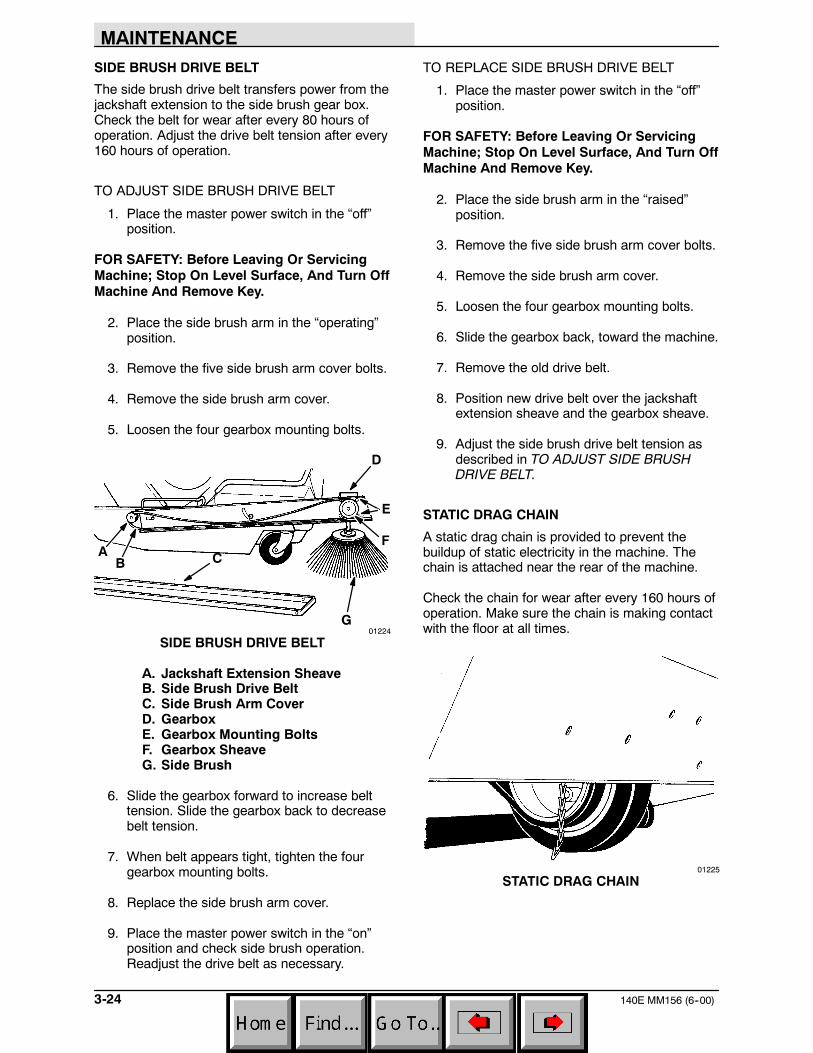
SIDE BRUSH DRIVE BELT
A. Jackshaft Extension SheaveB. Side Brush Drive BeltC. Side Brush Arm CoverD. GearboxE. Gearbox Mounting BoltsF. Gearbox SheaveG. Side Brush
6. Slide the gearbox forward to increase belttension. Slide the gearbox back to decreasebelt tension.
7. When belt appears tight, tighten the fourgearbox mounting bolts.
8. Replace the side brush arm cover.
9. Place the master power switch in the “on”position and check side brush operation.Readjust the drive belt as necessary.
TO REPLACE SIDE BRUSH DRIVE BELT
1. Place the master power switch in the “off”position.
FOR SAFETY: Before Leaving Or ServicingMachine; Stop On Level Surface, And Turn OffMachine And Remove Key.
2. Place the side brush arm in the “raised”position.
3. Remove the five side brush arm cover bolts.
4. Remove the side brush arm cover.
5. Loosen the four gearbox mounting bolts.
6. Slide the gearbox back, toward the machine.
7. Remove the old drive belt.
8. Position new drive belt over the jackshaftextension sheave and the gearbox sheave.
9. Adjust the side brush drive belt tension asdescribed in TO ADJUST SIDE BRUSHDRIVE BELT.
STATIC DRAG CHAIN
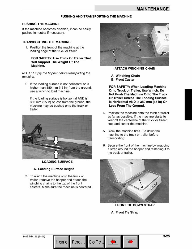
A static drag chain is provided to prevent thebuildup of static electricity in the machine. Thechain is attached near the rear of the machine.
Check the chain for wear after every 160 hours ofoperation. Make sure the chain is making contactwith the floor at all times.
01225
STATIC DRAG CHAIN
MAINTENANCE
3-25140E MM156 (8--01)
PUSHING AND TRANSPORTING THE MACHINE
PUSHING THE MACHINE
If the machine becomes disabled, it can be easilypushed in neutral if necessary.
TRANSPORTING THE MACHINE
1. Position the front of the machine at theloading edge of the truck or trailer.
FOR SAFETY: Use Truck Or Trailer ThatWill Support The Weight Of TheMachine.
NOTE: Empty the hopper before transporting themachine.
2. If the loading surface is not horizontal or ishigher than 380 mm (15 in) from the ground,use a winch to load machine.
If the loading surface is horizontal AND is380 mm (15 in) or less from the ground, themachine may be pushed onto the truck ortrailer.
LOADING SURFACE
A. Loading Surface Height
3. To winch the machine onto the truck ortrailer, remove the hopper and attach thewinching chains to the top of the frontcasters. Make sure the machine is centered.
A
B
ATTACH WINCHING CHAIN
A. Winching ChainB. Front Caster
FOR SAFETY: When Loading MachineOnto Truck or Trailer, Use Winch. DoNot Push The Machine Onto The TruckOr Trailer Unless The Loading SurfaceIs Horizontal AND Is 380 mm (15 in) OrLess From The Ground.
4. Position the machine onto the truck or traileras far as possible. If the machine starts toveer off the centerline of the truck or trailer,stop and center the machine.
5. Block the machine tires. Tie down themachine to the truck or trailer beforetransporting.
6. Secure the front of the machine by wrappinga strap around the hopper and fastening it tothe truck or trailer.
A
FRONT TIE DOWN STRAP
A. Front Tie Strap
MAINTENANCE
140E MM156 (8--01)3-26
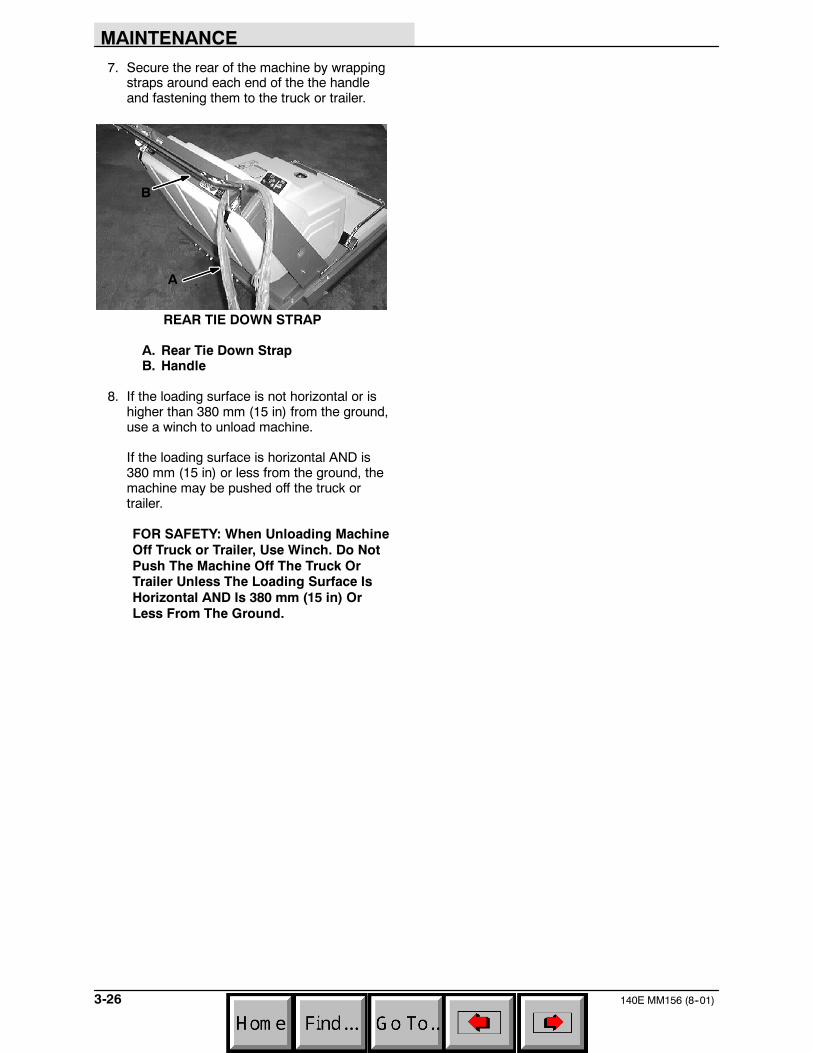
7. Secure the rear of the machine by wrappingstraps around each end of the the handleand fastening them to the truck or trailer.
A
B
REAR TIE DOWN STRAP
A. Rear Tie Down StrapB. Handle
8. If the loading surface is not horizontal or ishigher than 380 mm (15 in) from the ground,use a winch to unload machine.
If the loading surface is horizontal AND is380 mm (15 in) or less from the ground, themachine may be pushed off the truck ortrailer.
FOR SAFETY: When Unloading MachineOff Truck or Trailer, Use Winch. Do NotPush The Machine Off The Truck OrTrailer Unless The Loading Surface IsHorizontal AND Is 380 mm (15 in) OrLess From The Ground.
APPENDIX
4-1140E MM156 (3--88)
SECTION 4CONTENTS
PageHARDWARE INFORMATION 4-3. . . . . . . . . . . .
STANDARD BOLT TORQUE CHART 4-3. .METRIC BOLT TORQUE CHART 4-3. . . . .BOLT IDENTIFICATION 4-3. . . . . . . . . . . . . .THREAD SEALANT AND LOCKING
COMPOUNDS 4-3. . . . . . . . . . . . . . . . . . .

APPENDIX
140E MM156 (3--88)4-2
APPENDIX
4-3140E MM156 (12--96)
HARDWARE INFORMATION
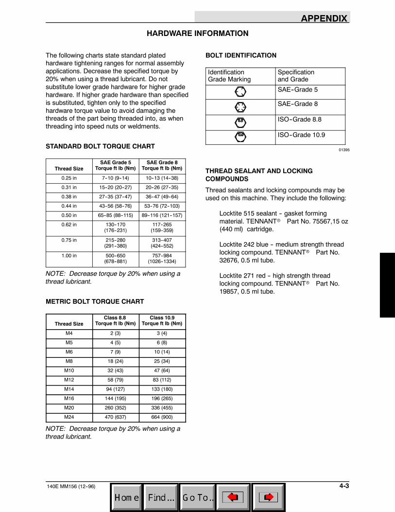
The following charts state standard platedhardware tightening ranges for normal assemblyapplications. Decrease the specified torque by20% when using a thread lubricant. Do notsubstitute lower grade hardware for higher gradehardware. If higher grade hardware than specifiedis substituted, tighten only to the specifiedhardware torque value to avoid damaging thethreads of the part being threaded into, as whenthreading into speed nuts or weldments.
STANDARD BOLT TORQUE CHART
Thread SizeSAE Grade 5
Torque ft lb (Nm)SAE Grade 8
Torque ft lb (Nm)
0.25 in 7--10 (9--14) 10--13 (14--38)
0.31 in 15--20 (20--27) 20--26 (27--35)
0.38 in 27--35 (37--47) 36--47 (49--64)
0.44 in 43--56 (58--76) 53--76 (72--103)
0.50 in 65--85 (88--115) 89--116 (121--157)
0.62 in 130--170(176--231)
117--265(159--359)
0.75 in 215--280(291--380)
313--407(424--552)
1.00 in 500--650(678--881)
757--984(1026--1334)
NOTE: Decrease torque by 20% when using athread lubricant.
METRIC BOLT TORQUE CHART
Thread SizeClass 8.8
Torque ft lb (Nm)Class 10.9
Torque ft lb (Nm)
M4 2 (3) 3 (4)
M5 4 (5) 6 (8)
M6 7 (9) 10 (14)
M8 18 (24) 25 (34)
M10 32 (43) 47 (64)
M12 58 (79) 83 (112)
M14 94 (127) 133 (180)
M16 144 (195) 196 (265)
M20 260 (352) 336 (455)
M24 470 (637) 664 (900)
NOTE: Decrease torque by 20% when using athread lubricant.
BOLT IDENTIFICATION
IdentificationGrade Marking
Specificationand Grade
SAE--Grade 5
SAE--Grade 8
ISO--Grade 8.8
ISO--Grade 10.9
01395
THREAD SEALANT AND LOCKINGCOMPOUNDS
Thread sealants and locking compounds may beused on this machine. They include the following:
Locktite 515 sealant -- gasket formingmaterial. TENNANTr Part No. 75567,15 oz(440 ml) cartridge.
Locktite 242 blue -- medium strength threadlocking compound. TENNANTr Part No.32676, 0.5 ml tube.
Locktite 271 red -- high strength threadlocking compound. TENNANTr Part No.19857, 0.5 ml tube.

APPENDIX
140E MM156 (3--88)4-4
HOW TO USE THIS MANUAL
5-1140E MM156 (12--00)
HOW TO USE THIS MANUAL
This section on HOW TO USE THIS MANUAL willtell you how to:
-- Find important machine information forordering correct repair parts.
-- Find TENNANT part numbers.-- Order TENNANT parts and supplies.
IMPORTANT INFORMATION
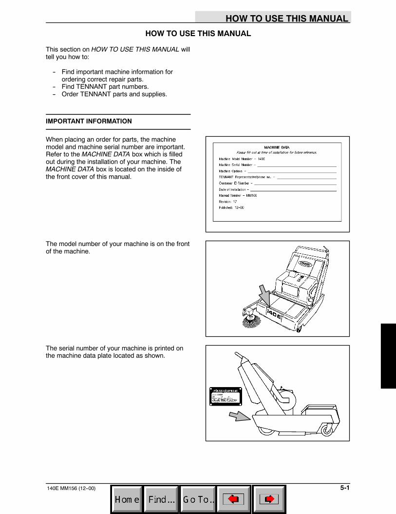
When placing an order for parts, the machinemodel and machine serial number are important.Refer to the MACHINE DATA box which is filledout during the installation of your machine. TheMACHINE DATA box is located on the inside ofthe front cover of this manual.
The model number of your machine is on the frontof the machine.
The serial number of your machine is printed onthe machine data plate located as shown.
HOW TO USE THIS MANUAL
140E MM156 (12--96)5-2
FINDING A TENNANT PART NUMBER
This manual contains the following sections:
-- HOW TO USE THIS MANUAL-- STANDARD PARTS-- OPTIONS-- BREAKDOWNS-- CROSS REFERENCE
The STANDARD PARTS section lists repair partsfor standard machines. They are grouped in thisgeneral order:
-- General wear parts.-- Machine frame and related parts.-- Machine propelling system.-- Scrubbing components.-- Electrical parts.
The OPTION section lists repair parts of options.
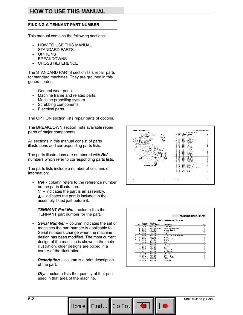
The BREAKDOWN section lists available repairparts of major components.
All sections in this manual consist of partsillustrations and corresponding parts lists.
The parts illustrations are numbered with Refnumbers which refer to corresponding parts lists.
The parts lists include a number of columns ofinformation:
-- Ref -- column refers to the reference numberon the parts illustration.∇ -- indicates the part is an assembly.Y -- indicates the part is included in theassembly listed just before it.
-- TENNANT Part No. -- column lists theTENNANT part number for the part.
-- Serial Number -- column indicates the set ofmachines the part number is applicable to.Serial numbers change when the machinedesign has been modified. The most currentdesign of the machine is shown in the mainillustration, older designs are boxed in acorner of the illustration.
-- Description -- column is a brief descriptionof the part.
-- Qty. -- column lists the quantity of that partused in that area of the machine.
HOW TO USE THIS MANUAL
5-3140E MM156 (12--96)
NOTE: If a service kit is installed on yourmachine, be sure to keep the INSTRUCTIONBULLETIN which came with the kit. It containsrepair parts numbers needed for ordering futureparts.
NOTE: Fasteners used in this machine may bemetric or non-metric. Take care when replacinghardware to replace with same thread size.
PLACING AN ORDER
Orders may be placed by phone, fax, or by mail.Phone orders may need written confirmation.Follow the steps below to insure prompt delivery:
1. Identify the model number of your machine.
2. Identify the serial number of your machine.
3. Find the part number of the part you need.Do not order by page number or referencenumber. If you are not able to find the partnumber, call your TENNANT representativefor help or send the old part as a sample.
4. Determine the quantity of the part you need.
5. Provide the following company information:
-- Company name
-- Customer ID Number
-- Shipping address
-- Billing address
-- First and last name of person orderingparts
-- Telephone number
-- Purchase order number
6. Provide definitive shipping instructions.
HOW TO USE THIS MANUAL
140E MM156 (12--96)5-4
Any claim for loss or damage to a shipment intransit should be filed promptly with thetransportation company making the delivery.Shipments will be complete unless the packing listor order acknowledgement indicates items backordered.
If parts received are suspected to be incorrect ordefective, please contact the TENNANTrepresentative from whom you ordered the part.They will give authorization for return and/orhandle replacement shipments when required.
STANDARD MODEL PARTS
6-1140E MM156 (12--96)
SECTION 6CONTENTS
PageFig. 1 -- Recommended General
Maintenance Items 6-3. . . . . . . . . . . . .Fig. 2 -- Replacement Brushes 6-4. . . . . . . . . . . . . .Fig. 3 -- Main Frame and Charger Group 6-6. . . . .Fig. 4 -- Handle Group 6-8. . . . . . . . . . . . . . . . . . . . .Fig. 5 -- Hopper Assembly 6-9. . . . . . . . . . . . . . . . . .Fig. 6 -- Brush Drive Group 6-10. . . . . . . . . . . . . . . . .Fig. 7 -- Motor and Wheel Drive Group 6-12. . . . . . .Fig. 8 -- Filter Group 6-14. . . . . . . . . . . . . . . . . . . . . . .Fig. 9 -- Battery Group 6-16. . . . . . . . . . . . . . . . . . . . .Fig. 10 -- Wire Harnesses Group 6-18. . . . . . . . . . . .Fig. 11 -- Vacuum Fan Group 6-20. . . . . . . . . . . . . . . .Fig. 12 -- Label Kit 6-21. . . . . . . . . . . . . . . . . . . . . . . . .
NOTE: SECTION 6, STANDARD MODEL PARTS,lists repair parts for a standard model machine.

STANDARD MODEL PARTS
140E MM156 (7--90)6-2
STANDARD MODEL PARTS
6-3140E MM156 (3--02)
01229
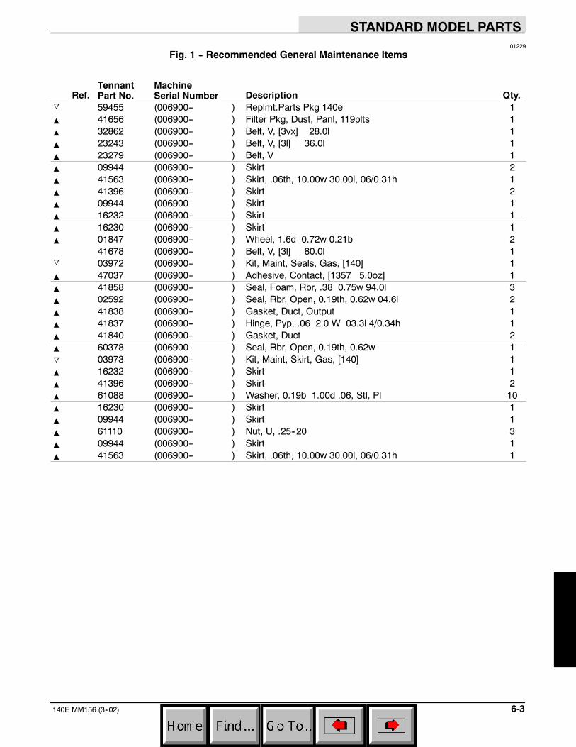
Fig. 1 -- Recommended General Maintenance Items
Ref.TennantPart No.
MachineSerial Number Description Qty.
o 59455 (006900-- ) Replmt.Parts Pkg 140e 1Y 41656 (006900-- ) Filter Pkg, Dust, Panl, 119plts 1Y 32862 (006900-- ) Belt, V, [3vx] 28.0l 1Y 23243 (006900-- ) Belt, V, [3l] 36.0l 1Y 23279 (006900-- ) Belt, V 1Y 09944 (006900-- ) Skirt 2Y 41563 (006900-- ) Skirt, .06th, 10.00w 30.00l, 06/0.31h 1Y 41396 (006900-- ) Skirt 2Y 09944 (006900-- ) Skirt 1Y 16232 (006900-- ) Skirt 1Y 16230 (006900-- ) Skirt 1Y 01847 (006900-- ) Wheel, 1.6d 0.72w 0.21b 2
41678 (006900-- ) Belt, V, [3l] 80.0l 1o 03972 (006900-- ) Kit, Maint, Seals, Gas, [140] 1Y 47037 (006900-- ) Adhesive, Contact, [1357 5.0oz] 1Y 41858 (006900-- ) Seal, Foam, Rbr, .38 0.75w 94.0l 3Y 02592 (006900-- ) Seal, Rbr, Open, 0.19th, 0.62w 04.6l 2Y 41838 (006900-- ) Gasket, Duct, Output 1Y 41837 (006900-- ) Hinge, Pyp, .06 2.0 W 03.3l 4/0.34h 1Y 41840 (006900-- ) Gasket, Duct 2Y 60378 (006900-- ) Seal, Rbr, Open, 0.19th, 0.62w 1o 03973 (006900-- ) Kit, Maint, Skirt, Gas, [140] 1Y 16232 (006900-- ) Skirt 1Y 41396 (006900-- ) Skirt 2Y 61088 (006900-- ) Washer, 0.19b 1.00d .06, Stl, Pl 10Y 16230 (006900-- ) Skirt 1Y 09944 (006900-- ) Skirt 1Y 61110 (006900-- ) Nut, U, .25--20 3Y 09944 (006900-- ) Skirt 1Y 41563 (006900-- ) Skirt, .06th, 10.00w 30.00l, 06/0.31h 1
STANDARD MODEL PARTS
140E MM156 (6--00)6-4
1
2
3
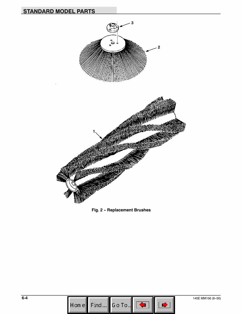
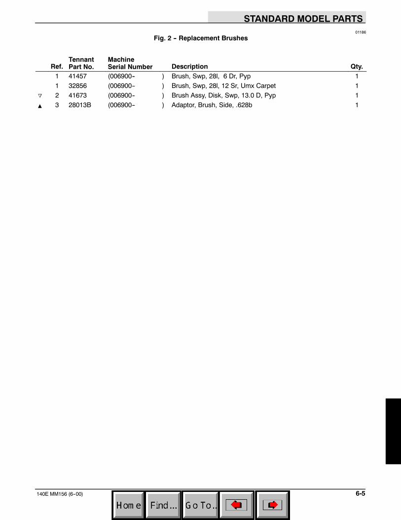
Fig. 2 -- Replacement Brushes
STANDARD MODEL PARTS
6-5140E MM156 (6--00)
01186
Fig. 2 -- Replacement Brushes
Ref.TennantPart No.
MachineSerial Number Description Qty.
1 41457 (006900-- ) Brush, Swp, 28l, 6 Dr, Pyp 1
1 32856 (006900-- ) Brush, Swp, 28l, 12 Sr, Umx Carpet 1
o 2 41673 (006900-- ) Brush Assy, Disk, Swp, 13.0 D, Pyp 1
Y 3 28013B (006900-- ) Adaptor, Brush, Side, .628b 1
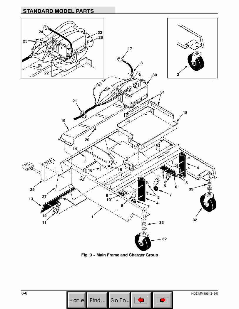
STANDARD MODEL PARTS
140E MM156 (3--94)6-6
1
32
3
4
5
6
78
910
11
12
13
14
1516
17
18
19
20
21
2324
2526
28
29
30
32
4
55
7
22
27
31
33
33
2
Fig. 3 -- Main Frame and Charger Group
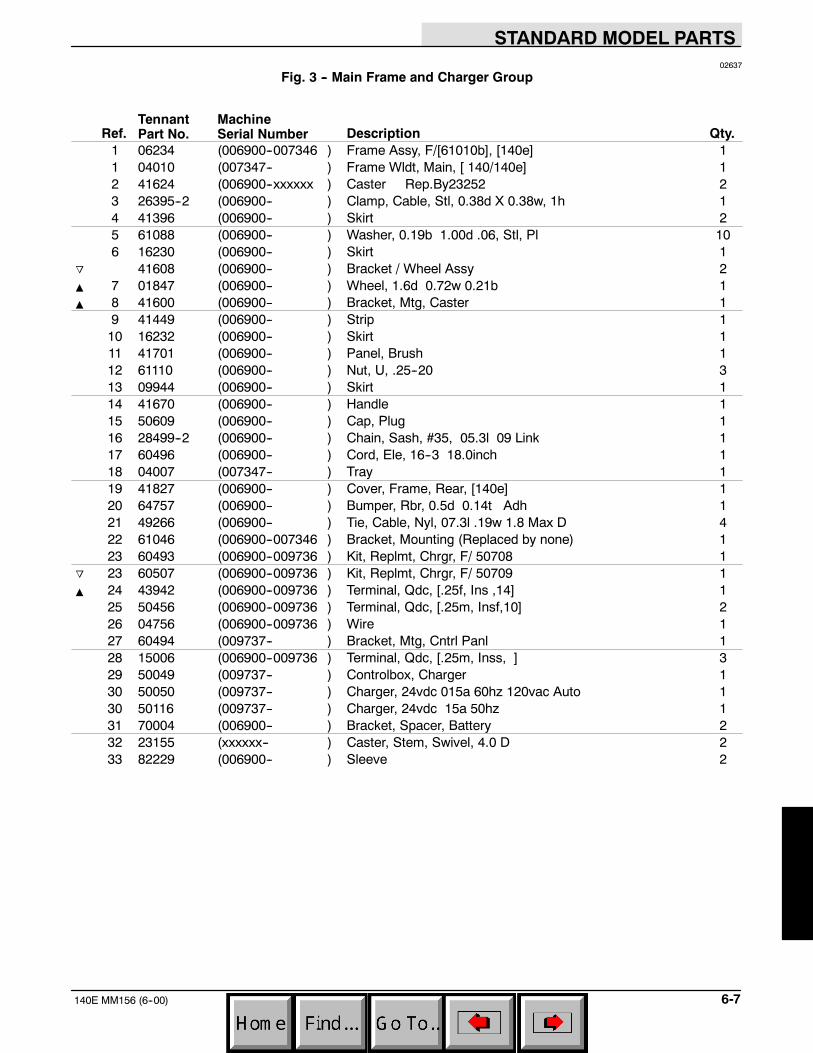
STANDARD MODEL PARTS
6-7140E MM156 (6--00)
02637
Fig. 3 -- Main Frame and Charger Group
Ref.TennantPart No.
MachineSerial Number Description Qty.
1 06234 (006900--007346 ) Frame Assy, F/[61010b], [140e] 11 04010 (007347-- ) Frame Wldt, Main, [ 140/140e] 12 41624 (006900--xxxxxx ) Caster Rep.By23252 23 26395--2 (006900-- ) Clamp, Cable, Stl, 0.38d X 0.38w, 1h 14 41396 (006900-- ) Skirt 25 61088 (006900-- ) Washer, 0.19b 1.00d .06, Stl, Pl 106 16230 (006900-- ) Skirt 1
o 41608 (006900-- ) Bracket / Wheel Assy 2Y 7 01847 (006900-- ) Wheel, 1.6d 0.72w 0.21b 1Y 8 41600 (006900-- ) Bracket, Mtg, Caster 1
9 41449 (006900-- ) Strip 110 16232 (006900-- ) Skirt 111 41701 (006900-- ) Panel, Brush 112 61110 (006900-- ) Nut, U, .25--20 313 09944 (006900-- ) Skirt 114 41670 (006900-- ) Handle 115 50609 (006900-- ) Cap, Plug 116 28499--2 (006900-- ) Chain, Sash, #35, 05.3l 09 Link 117 60496 (006900-- ) Cord, Ele, 16--3 18.0inch 118 04007 (007347-- ) Tray 119 41827 (006900-- ) Cover, Frame, Rear, [140e] 120 64757 (006900-- ) Bumper, Rbr, 0.5d 0.14t Adh 121 49266 (006900-- ) Tie, Cable, Nyl, 07.3l .19w 1.8 Max D 422 61046 (006900--007346 ) Bracket, Mounting (Replaced by none) 123 60493 (006900--009736 ) Kit, Replmt, Chrgr, F/ 50708 1
o 23 60507 (006900--009736 ) Kit, Replmt, Chrgr, F/ 50709 1Y 24 43942 (006900--009736 ) Terminal, Qdc, [.25f, Ins ,14] 1
25 50456 (006900--009736 ) Terminal, Qdc, [.25m, Insf,10] 226 04756 (006900--009736 ) Wire 127 60494 (009737-- ) Bracket, Mtg, Cntrl Panl 128 15006 (006900--009736 ) Terminal, Qdc, [.25m, Inss, ] 329 50049 (009737-- ) Controlbox, Charger 130 50050 (009737-- ) Charger, 24vdc 015a 60hz 120vac Auto 130 50116 (009737-- ) Charger, 24vdc 15a 50hz 131 70004 (006900-- ) Bracket, Spacer, Battery 232 23155 (xxxxxx-- ) Caster, Stem, Swivel, 4.0 D 233 82229 (006900-- ) Sleeve 2
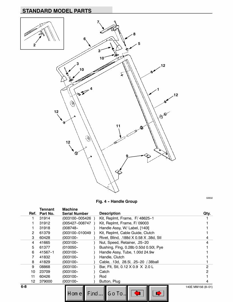
STANDARD MODEL PARTS
140E MM156 (8--01)6-8
1
9
3
56
7
8
10
11
3
4
10
2
12
12
12
12
02632
Fig. 4 -- Handle Group
Ref.TennantPart No.
MachineSerial Number Description Qty.
1 31914 (003100--005426 ) Kit, Replmt, Frame, F/ 48625--1 11 31912 (005427--008747 ) Kit, Replmt, Frame, F/ 09003 11 31918 (008748-- ) Handle Assy, W/ Label, [140l] 12 61379 (003100--010049 ) Kit, Replmt, Cable Guide, Clutch 13 60428 (003100-- ) Rivet, Blind, .188d X 0.58 X .38d, Stl 44 41665 (003100-- ) Nut, Speed, Retainer, .25--20 45 61377 (010050-- ) Bushing, Flng, 0.28b 0.50d 0.50l, Pye 16 41567--1 (003100-- ) Handle Assy, Tube, 1.00d 24.9w 17 41832 (003100-- ) Handle, Clutch 18 41829 (003100-- ) Cable, .13d, 28.5l, .25--20 /.38ball 19 08868 (003100-- ) Bar, Flt, Stl, 0.12 X 0.9 X 2.0 L 2
10 23709 (003100-- ) Catch 211 60426 (003100-- ) Rod 112 379000 (003100-- ) Button, Plug 4
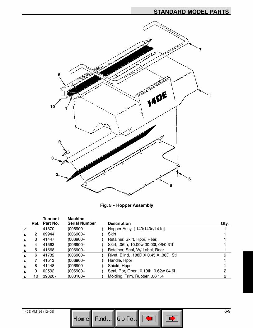
STANDARD MODEL PARTS
6-9140E MM156 (12--09)
7
1
5
9
3
2
86
410
Fig. 5 -- Hopper Assembly
Ref.TennantPart No.
MachineSerial Number Description Qty.
o 1 41870 (006900-- ) Hopper Assy, [ 140/140e/141e] 1Y 2 09944 (006900-- ) Skirt 1Y 3 41447 (006900-- ) Retainer, Skirt, Hppr, Rear, 1Y 4 41563 (006900-- ) Skirt, .06th, 10.00w 30.00l, 06/0.31h 1Y 5 41568 (006900-- ) Retainer, Seal, W/ Label, Rear 1Y 6 41732 (006900-- ) Rivet, Blind, .188D X 0.45 X .38D, Stl 9Y 7 41513 (006900-- ) Handle, Hppr 1Y 8 41448 (006900-- ) Shield, Hppr 1Y 9 02592 (006900-- ) Seal, Rbr, Open, 0.19th, 0.62w 04.6l 2Y 10 398207 (003100-- ) Molding, Trim, Rubber, .06 1.4l 2
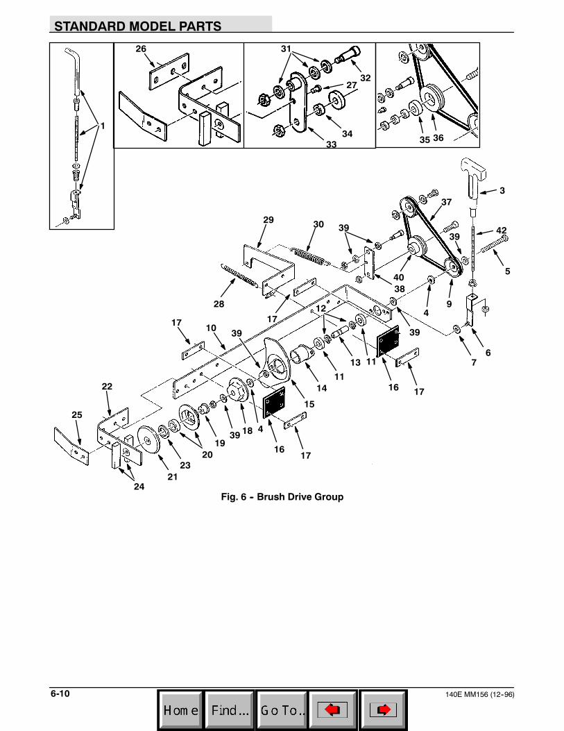
STANDARD MODEL PARTS
140E MM156 (12--96)6-10
32
26 31
3334
35 36
3
42
4
5
67
9
10
11
12
13
14
15
1617
1819
20
21
22
23
24
25
27
28
29 30
37
38
39
40
16 17
17 174
11
1
39
3939
39
Fig. 6 -- Brush Drive Group

STANDARD MODEL PARTS
6-11140E MM156 (12--06)
02639
Fig. 6 -- Brush Drive Group
Ref.TennantPart No.
MachineSerial Number Description Qty.
1 25147 (006900--010682 ) Kit, Replmt, Handle / Bracket 12 41743 (006900--010682 ) Bushing, Flng, 0.30b 0.52d . L, Nyl 13 25950 (010683-- ) Handle, Lift, Brush, [140l] 14 41142 (006900-- ) Washer, Lock, Int--Ext, .38 15 21198 (006900-- ) Screw, Hex, .38--16 X 1.25, 5 16 25148 (010683-- ) Bracket Wldt, Brush Lift 17 24924 (006900-- ) Washer, 0.28b 0.62d .06, Nyl 18 32553 (006900--010682 ) Spring, Cmpr, 0.72od .55wir 3.0l 19 32562 (006900-- ) Sheave, [3v], 1grv, 03.5pd 0.38b 110 16237 (006900-- ) Arm, Brush, Main, Drive 1
o 41648 (006900-- ) Shaft 1Y 11 41360AM (006900-- ) Bearing, Ball, 0.59b 1.26d 0.35w 2Y 12 01516 (006900-- ) Ring, Retaining, Ext, 0.59d, Basic 2Y 13 47751 (006900-- ) Shaft 1Y 14 41362 (006900-- ) Bushing Assy, Flng, 2 Hole, 1.25b 1
15 41363 (006900-- ) Cover, Flng, Drive, Gray 116 41837 (006900-- ) Hinge, Pyp, .06 2.0 W 03.3l 4/0.34h 217 41411 (006900-- ) Strip, Stl, 0.07th X 00.90w, 03.30l 418 41357 (006900-- ) Cup,Drive,Brush Tube--Grey 1
o 41518 (006900-- ) Arm Assy, Brush, Main, [140] 1Y 19 41385 (006900-- ) Bar, Hex, Stl, Mach, Sleeve, Idler 1Y 20 41649 (006900-- ) Cup & Bearing Assy --Brush 1Y 21 41386 (006900-- ) Guard, Cup, Gray 1Y 22 41509 (006900-- ) Arm, Brush, Main, Rh 1Y 23 09006 (006900-- ) Washer 1
24 41637 (006900-- ) Seal, Foam, Rbr, .50 0.75w 03.0l 225 41669 (006900-- ) Plate 126 41864 (006900--008073 ) Plate Rep.Bynone 127 39019 (006900--008087 ) Pin, Clevis, 0.37 D X 0.75l 128 29260 (006900-- ) Spring, Extn, 0.75od X 0.06wir, 5.3l 129 41741 (006900-- ) Bracket, Mtg, Spring 130 29499 (006900-- ) Spring, Extn, 0.75od X 0.11wir, 4.5l 131 41818 (006900--008087 ) Washer, 0.38b 0.56d .03, Stl 332 56060 (006900--008087 ) Bolt, Shld, .38d X 1.00, .31--18 133 09971 (006900--008087 ) Kit, Replmt, Idler Arm, F/ 41817 134 49566 (006900--008087 ) Sleeve 135 01845 (006900--009133 ) Bearing, Ball, 0.39b 1.18d 0.35w 136 50038 (006900--009133 ) Kit, Replmt, Idler, F/ [41819&47] 137 32862 (006900-- ) Belt, V, [3vx] 28.0l 138 09945 (008088-- ) Idler Arm 139 32491 (008088-- ) Washer, Flt, .31 Std 640 02355 (009134-- ) Sheave, [3v], 1grv, 03.0pd 0.38brg 141 24227 (006900--010682 ) Washer, Flat 142 31906 (010683-- ) Rod, Thrd, Full, .31--18 05.7l 1
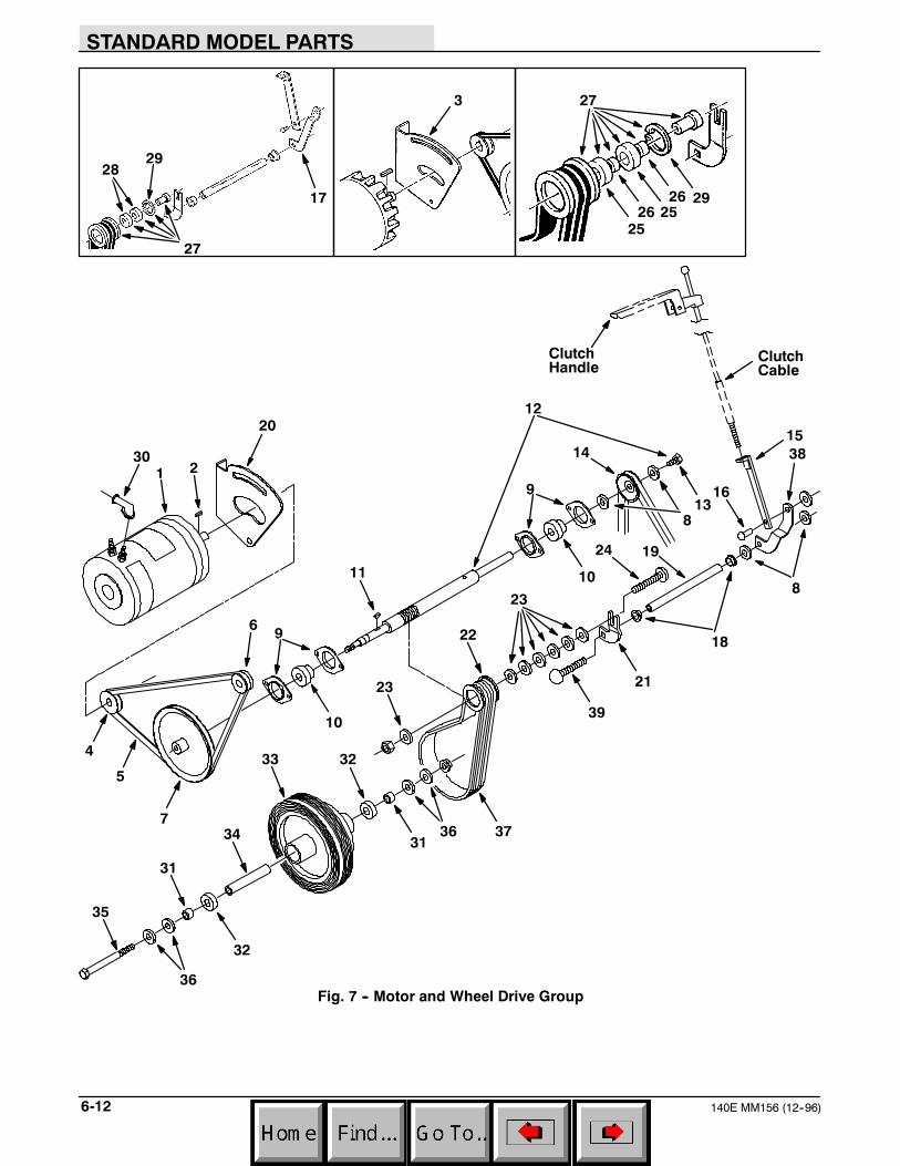
STANDARD MODEL PARTS
140E MM156 (12--96)6-12
ClutchHandle
ClutchCable
1
3
17
28
2
4
5
6
7
9
11
12
13
1415
16
18
19
21
27
292526
23
24
31
32
33
34
35
8
36 37
38
20
25
26
30
9
10
10
31
32
36
23
22
29
27
39
8
Fig. 7 -- Motor and Wheel Drive Group
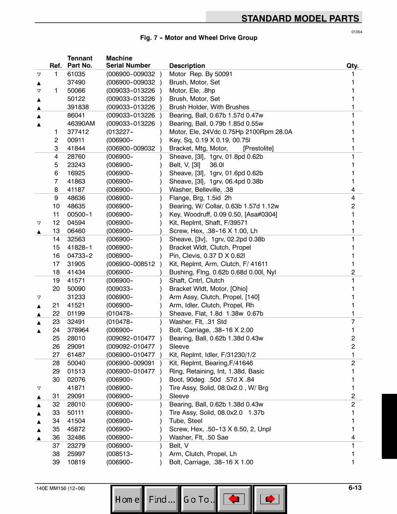
STANDARD MODEL PARTS
6-13140E MM156 (12--06)
01054
Fig. 7 -- Motor and Wheel Drive Group
Ref.TennantPart No.
MachineSerial Number Description Qty.
o 1 61035 (006900--009032 ) Motor Rep. By 50091 1Y 37490 (006900--009032 ) Brush, Motor, Set 1o 1 50066 (009033--013226 ) Motor, Ele, .8hp 1Y 50122 (009033--013226 ) Brush, Motor, Set 1Y 391838 (009033--013226 ) Brush Holder, With Brushes 1Y 86041 (009033--013226 ) Bearing, Ball, 0.67b 1.57d 0.47w 1Y 46390AM (009033--013226 ) Bearing, Ball, 0.79b 1.85d 0.55w 1
1 377412 (013227-- ) Motor, Ele, 24Vdc 0.75Hp 2100Rpm 28.0A 12 00911 (006900-- ) Key, Sq, 0.19 X 0.19, 00.75l 13 41844 (006900--009032 ) Bracket, Mtg, Motor, [Prestolite] 14 28760 (006900-- ) Sheave, [3l], 1grv, 01.8pd 0.62b 15 23243 (006900-- ) Belt, V, [3l] 36.0l 16 16925 (006900-- ) Sheave, [3l], 1grv, 01.6pd 0.62b 17 41863 (006900-- ) Sheave, [3l], 1grv, 06.4pd 0.38b 18 41187 (006900-- ) Washer, Belleville, .38 49 48636 (006900-- ) Flange, Brg, 1.5id 2h 410 48635 (006900-- ) Bearing, W/ Collar, 0.63b 1.57d 1.12w 211 00500--1 (006900-- ) Key, Woodruff, 0.09 0.50, [Asa#0304] 1
o 12 04594 (006900-- ) Kit, Replmt, Shaft, F/39571 1Y 13 06460 (006900-- ) Screw, Hex, .38--16 X 1.00, Lh 1
14 32563 (006900-- ) Sheave, [3v], 1grv, 02.2pd 0.38b 115 41828--1 (006900-- ) Bracket Wldt, Clutch, Propel 116 04733--2 (006900-- ) Pin, Clevis, 0.37 D X 0.62l 117 31905 (006900--008512 ) Kit, Replmt, Arm, Clutch, F/ 41611 118 41434 (006900-- ) Bushing, Flng, 0.62b 0.68d 0.00l, Nyl 219 41571 (006900-- ) Shaft, Cntrl, Clutch 120 50090 (009033-- ) Bracket Wldt, Motor, [Ohio] 1
o 31233 (006900-- ) Arm Assy, Clutch, Propel, [140] 1Y 21 41521 (006900-- ) Arm, Idler, Clutch, Propel, Rh 1Y 22 01199 (010478-- ) Sheave, Flat, 1.8d 1.38w 0.67b 1Y 23 32491 (010478-- ) Washer, Flt, .31 Std 7Y 24 378964 (006900-- ) Bolt, Carriage, .38--16 X 2.00 1
25 28010 (009092--010477 ) Bearing, Ball, 0.62b 1.38d 0.43w 226 29091 (009092--010477 ) Sleeve 227 61487 (006900--010477 ) Kit, Replmt, Idler, F/31230/1/2 128 50040 (006900--009091 ) Kit, Replmt, Bearing,F/41646 229 01513 (006900--010477 ) Ring, Retaining, Int, 1.38d, Basic 130 02076 (006900-- ) Boot, 90deg .50d .57d X .84 1
o 41871 (006900-- ) Tire Assy, Solid, 08.0x2.0 , W/ Brg 1Y 31 29091 (006900-- ) Sleeve 2Y 32 28010 (006900-- ) Bearing, Ball, 0.62b 1.38d 0.43w 2Y 33 50111 (006900-- ) Tire Assy, Solid, 08.0x2.0 1.37b 1Y 34 41504 (006900-- ) Tube, Steel 1Y 35 45872 (006900-- ) Screw, Hex, .50--13 X 6.50, 2, Unpl 1Y 36 32486 (006900-- ) Washer, Flt, .50 Sae 4
37 23279 (006900-- ) Belt, V 138 25997 (008513-- ) Arm, Clutch, Propel, Lh 139 10819 (006900-- ) Bolt, Carriage, .38--16 X 1.00 1
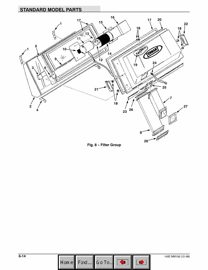
STANDARD MODEL PARTS
140E MM156 (12--96)6-14
1
1
2
3
4
5
6
7
8
9
10
11
12
13
14
1516
17
18
19
20
21
22
23
24
25
26
27
18
17
18
26
Fig. 8 -- Filter Group

STANDARD MODEL PARTS
6-15140E MM156 (6--00)
01053
Fig. 8 -- Filter Group
Ref.TennantPart No.
MachineSerial Number Description Qty.
1 12881 (006900-- ) Clip, Latch 22 02558 (006900-- ) Cover, Filterbox, Rear 13 41824A (006900-- ) Retainer 14 41549 (006900-- ) Bracket, Pivot, Fltr Cover 15 41656 (006900-- ) Filter Pkg, Dust, Panl, 119plts 16 40282 (006900-- ) Sleeve 27 41573 (006900-- ) Duct, Outlet, 3.0 3.0 7.8l Pye 18 41574 (006900-- ) Duct, Input 1
o 02421 (006900-- ) Shaker, Filter, Dust 1Y 9 31271 (006900-- ) Frame, Shaker, Fltr, [140e] 1Y 10 36661 (006900-- ) Bar, Flt, Rbr, 0.06 X 1.00 X 4.00l 1Y 11 44939 (006900-- ) Motor, Ele, 36vdc Hp Shaker 1Y 12 34773 (006900-- ) Weight, Eccentric 1Y 13 20634 (006900-- ) Screw, Set, #10--24 X 0.25, Nl 2Y 14 36658 (006900-- ) Bar, Flt, Rbr, 0.06 X 4.00 X 5.00l 1Y 15 36666 (006900-- ) Strap 1
16 34217 (006900-- ) Insulation, Acstc, 1.0th, 03.9w X 04.8l 117 41858 (006900-- ) Seal, Foam, Rbr, .38 0.75w 94.0l 318 41845 (006900-- ) Nut, Isolator, .25--20 #1/4--S 619 32556 (006900-- ) Retainer 120 02414 (006900-- ) Cover, Filterbox, Front, W/ Logo 121 48662 (006900-- ) Bracket, Retainer, Fltr, Rh 122 48661 (006900-- ) Bracket, Retainer, Fltr, Lh 123 41612 (006900-- ) Retainer Rep.By61381 124 47591 (006900--006944 ) Strainrelief 124 29232 (006945-- ) Strainrelief 125 41839 (006900-- ) Gasket, Duct 126 41840 (006900-- ) Gasket, Duct 227 41838 (006900-- ) Gasket, Duct, Output 1
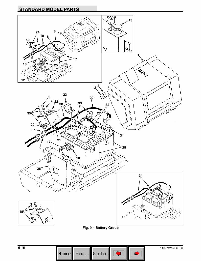
STANDARD MODEL PARTS
140E MM156 (6--03)6-16
1
1924
16 25
14
12
32
45
6
7
8
9
10
11
13
35
17
18
20
21
22
23
26
27
28
29
30
31
3233
34
15
Fig. 9 -- Battery Group
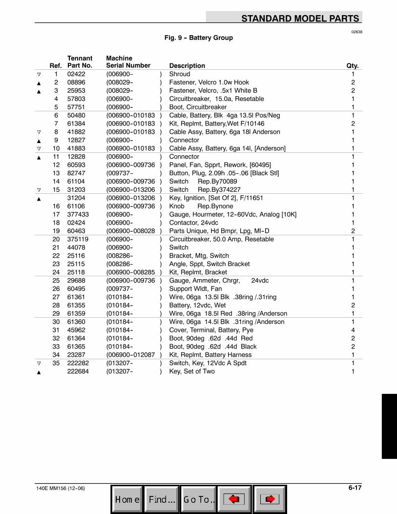
STANDARD MODEL PARTS
6-17140E MM156 (12--06)
02638
Fig. 9 -- Battery Group
Ref.TennantPart No.
MachineSerial Number Description Qty.
o 1 02422 (006900-- ) Shroud 1Y 2 08896 (008029-- ) Fastener, Velcro 1.0w Hook 2Y 3 25953 (008029-- ) Fastener, Velcro, .5x1 White B 2
4 57803 (006900-- ) Circuitbreaker, 15.0a, Resetable 15 57751 (006900-- ) Boot, Circuitbreaker 16 50480 (006900--010183 ) Cable, Battery, Blk 4ga 13.5l Pos/Neg 17 61384 (006900--010183 ) Kit, Replmt, Battery,Wet F/10146 2
o 8 41882 (006900--010183 ) Cable Assy, Battery, 6ga 18l Anderson 1Y 9 12827 (006900-- ) Connector 1o 10 41883 (006900--010183 ) Cable Assy, Battery, 6ga 14l, [Anderson] 1Y 11 12828 (006900-- ) Connector 1
12 60593 (006900--009736 ) Panel, Fan, Spprt, Rework, [60495] 113 82747 (009737-- ) Button, Plug, 2.09h .05--.06 [Black Stl] 114 61104 (006900--009736 ) Switch Rep.By70089 1
o 15 31203 (006900--013206 ) Switch Rep.By374227 1Y 31204 (006900--013206 ) Key, Ignition, [Set Of 2], F/11651 1
16 61106 (006900--009736 ) Knob Rep.Bynone 117 377433 (006900-- ) Gauge, Hourmeter, 12--60Vdc, Analog [10K] 118 02424 (006900-- ) Contactor, 24vdc 119 60463 (006900--008028 ) Parts Unique, Hd Bmpr, Lpg, Ml--D 220 375119 (006900-- ) Circuitbreaker, 50.0 Amp, Resetable 121 44078 (006900-- ) Switch 122 25116 (008286-- ) Bracket, Mtg, Switch 123 25115 (008286-- ) Angle, Sppt, Switch Bracket 124 25118 (006900--008285 ) Kit, Replmt, Bracket 125 29688 (006900--009736 ) Gauge, Ammeter, Chrgr, 24vdc 126 60495 (009737-- ) Support Wldt, Fan 127 61361 (010184-- ) Wire, 06ga 13.5l Blk .38ring /.31ring 128 61355 (010184-- ) Battery, 12vdc, Wet 229 61359 (010184-- ) Wire, 06ga 18.5l Red .38ring /Anderson 130 61360 (010184-- ) Wire, 06ga 14.5l Blk .31ring /Anderson 131 45962 (010184-- ) Cover, Terminal, Battery, Pye 432 61364 (010184-- ) Boot, 90deg .62d .44d Red 233 61365 (010184-- ) Boot, 90deg .62d .44d Black 234 23287 (006900--012087 ) Kit, Replmt, Battery Harness 1
o 35 222282 (013207-- ) Switch, Key, 12Vdc A Spdt 1Y 222684 (013207-- ) Key, Set of Two 1
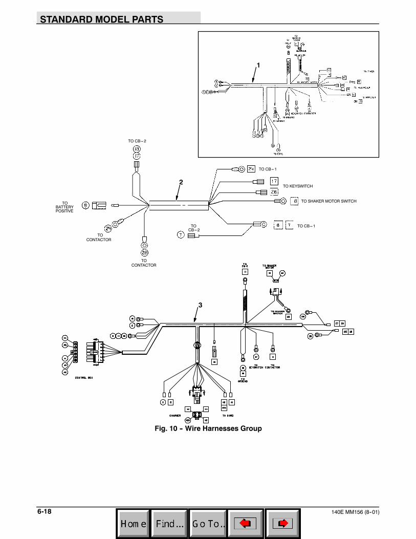
STANDARD MODEL PARTS
140E MM156 (8--01)6-18
1
2
TO CB---2
TOBATTERYPOSITIVE
TO
TOCB---2
TOCONTACTOR
TO CB---1
TO KEYSWITCH
TO SHAKER MOTOR SWITCH
TO CB---1
CONTACTOR
3
Fig. 10 -- Wire Harnesses Group

STANDARD MODEL PARTS
6-19140E MM156 (6--00)
02640
Fig. 10 -- Wire Harnesses Group
Ref.TennantPart No.
MachineSerial Number Description Qty.
o 1 02427 (006900--009736 ) Harness, [ 140e], Fltr Shakr 1Y 12828 (006900--009736 ) Connector 1o 2 02432 (006900-- ) Harness, Controller, Shakr, [140e] 1Y 12827 (006900-- ) Connector 1
3 60487 (009737-- ) Harness, Main, [ 140e] 1
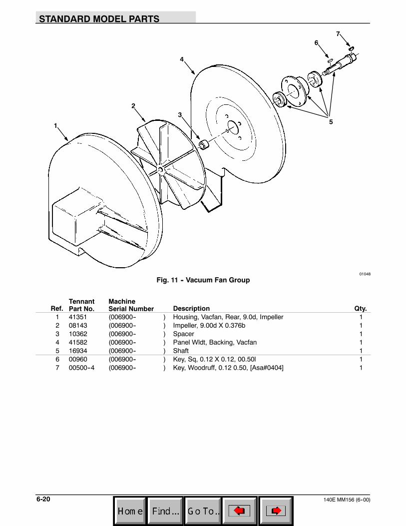
STANDARD MODEL PARTS
140E MM156 (6--00)6-20
1
23
4
5
67
01048
Fig. 11 -- Vacuum Fan Group
Ref.TennantPart No.
MachineSerial Number Description Qty.
1 41351 (006900-- ) Housing, Vacfan, Rear, 9.0d, Impeller 12 08143 (006900-- ) Impeller, 9.00d X 0.376b 13 10362 (006900-- ) Spacer 14 41582 (006900-- ) Panel Wldt, Backing, Vacfan 15 16934 (006900-- ) Shaft 16 00960 (006900-- ) Key, Sq, 0.12 X 0.12, 00.50l 17 00500--4 (006900-- ) Key, Woodruff, 0.12 0.50, [Asa#0404] 1
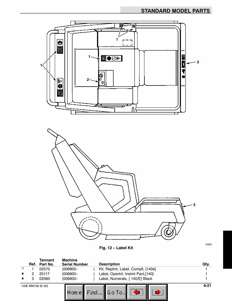
STANDARD MODEL PARTS
6-21140E MM156 (6--00)
1
1
1
2
3
3
04655
Fig. 12 -- Label Kit
Ref.TennantPart No.
MachineSerial Number Description Qty.
o 1 02575 (006900-- ) Kit, Replmt, Label, Complt, [140e] 1Y 2 25117 (006900-- ) Label, Opertnl, Instmt Panl,[140] 1Y 3 02560 (006900-- ) Label, Numerals, [ 140/E] Black 1

STANDARD MODEL PARTS
140E MM156 (12--96)6-22
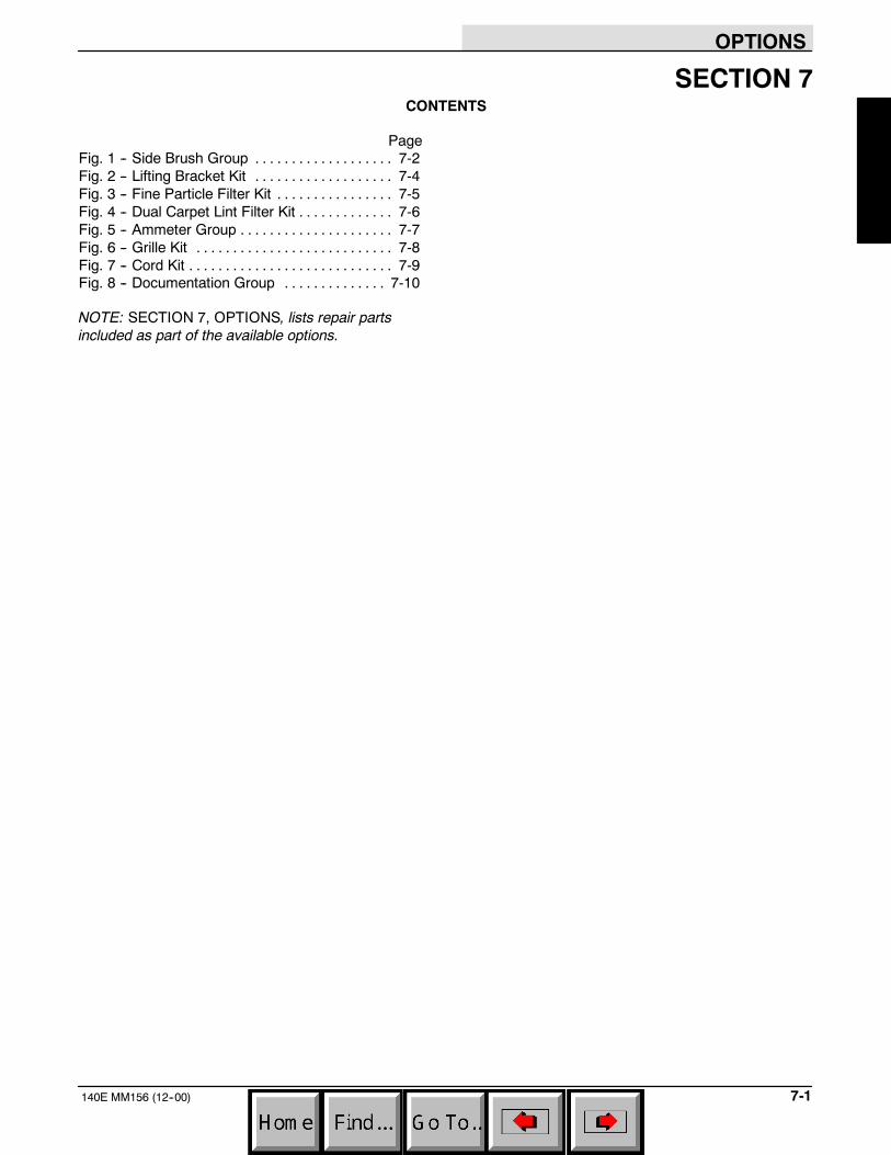
OPTIONS
7-1140E MM156 (12--00)
SECTION 7CONTENTS
PageFig. 1 -- Side Brush Group 7-2. . . . . . . . . . . . . . . . . . .Fig. 2 -- Lifting Bracket Kit 7-4. . . . . . . . . . . . . . . . . . .Fig. 3 -- Fine Particle Filter Kit 7-5. . . . . . . . . . . . . . . .Fig. 4 -- Dual Carpet Lint Filter Kit 7-6. . . . . . . . . . . . .Fig. 5 -- Ammeter Group 7-7. . . . . . . . . . . . . . . . . . . . .Fig. 6 -- Grille Kit 7-8. . . . . . . . . . . . . . . . . . . . . . . . . . .Fig. 7 -- Cord Kit 7-9. . . . . . . . . . . . . . . . . . . . . . . . . . . .Fig. 8 -- Documentation Group 7-10. . . . . . . . . . . . . .
NOTE: SECTION 7, OPTIONS, lists repair partsincluded as part of the available options.
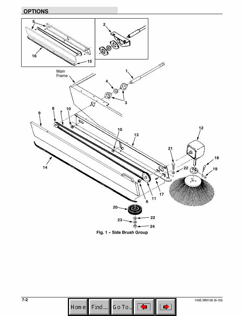
OPTIONS
140E MM156 (6--03)7-2
2
1516
5
1MainFrame
3
4
6
78
910
11
12
13
14
17
20
19
18
10
21
22
2223
24
Fig. 1 -- Side Brush Group

OPTIONS
7-3140E MM156 (6--03)
01034
Fig. 1 -- Side Brush Group
Ref.TennantPart No.
MachineSerial Number Description Qty.
1 48451 (003100-- ) Shaft, Drive, Brush, Side 12 48423 (003100--010239 ) Plate, Mtg, Bracket 13 48636 (003100-- ) Flange, Brg, 1.5id 2h 24 48635 (003100-- ) Bearing, W/ Collar, 0.63b 1.57d 1.12w 15 07894 (003100--008426 ) Arm, Brush, Side 16 39562 (003100-- ) Nut, Hex, Jam, .38--16, Lh 17 41678 (003100-- ) Belt, V, [3l] 80.0l 18 48452 (003100-- ) Sheave, [3l], 1grv, 01.4pd .38--16 19 07890 (008427-- ) Cover Wldt, Brush Arm 1
10 01047 (003100-- ) Retainer 211 07872 (003100-- ) Sheave, [3l], 1grv, 02.9pd .38--16 112 41731 (003100-- ) Gearbox, 90, :1ratio, Brush, Side 113 07891 (008427-- ) Arm, Brush, Side 114 07887 (008427-- ) Molding, Trim, .08--.11 39.20 115 41927 (003100--008426 ) Bumper, Side Brush 116 62595--14 (003100--008426 ) Molding, Trim, .08--.11 44.00 117 41708 (003100-- ) Screw, Btn, .25--20 X 0.62, Nl 418 08085 (003100-- ) Pin, Hair Cotter, 0.31 D .058 Wir 119 15173 (003100-- ) Pin, Clevis, 0.25 D X 1.25l 1
o 04188 (003100-- ) Wheel Assy, 4.0d 0.81w 1Y 20 23295 (003100-- ) Wheel, 4.0d 0.81w 0.25b 1Y 21 39528 (003100-- ) Screw, Hex, .25--20X2.00, 5 1Y 22 32490 (003100-- ) Washer, Flat, 0.25 Std 2Y 23 32982 (003100-- ) Washer, Lock, Int, .25 1Y 24 19312 (003100-- ) Nut, Hex, Std, M10X1.5 1
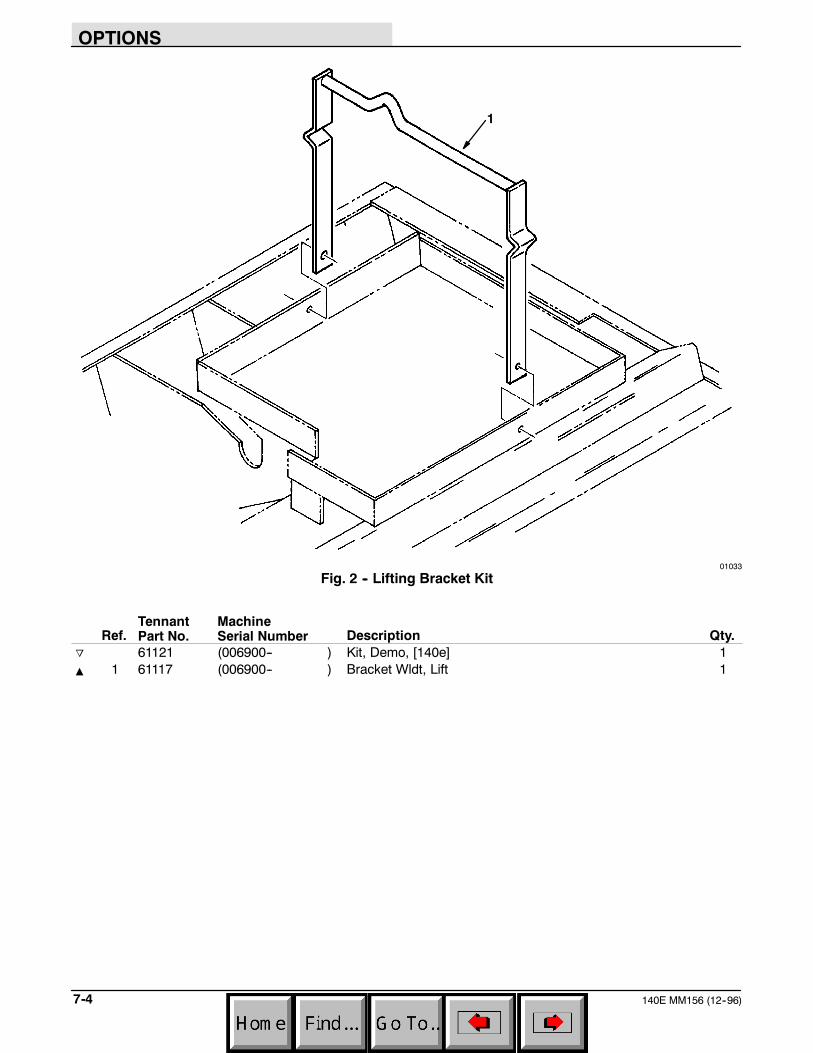
OPTIONS
140E MM156 (12--96)7-4
1
01033
Fig. 2 -- Lifting Bracket Kit
Ref.TennantPart No.
MachineSerial Number Description Qty.
o 61121 (006900-- ) Kit, Demo, [140e] 1Y 1 61117 (006900-- ) Bracket Wldt, Lift 1
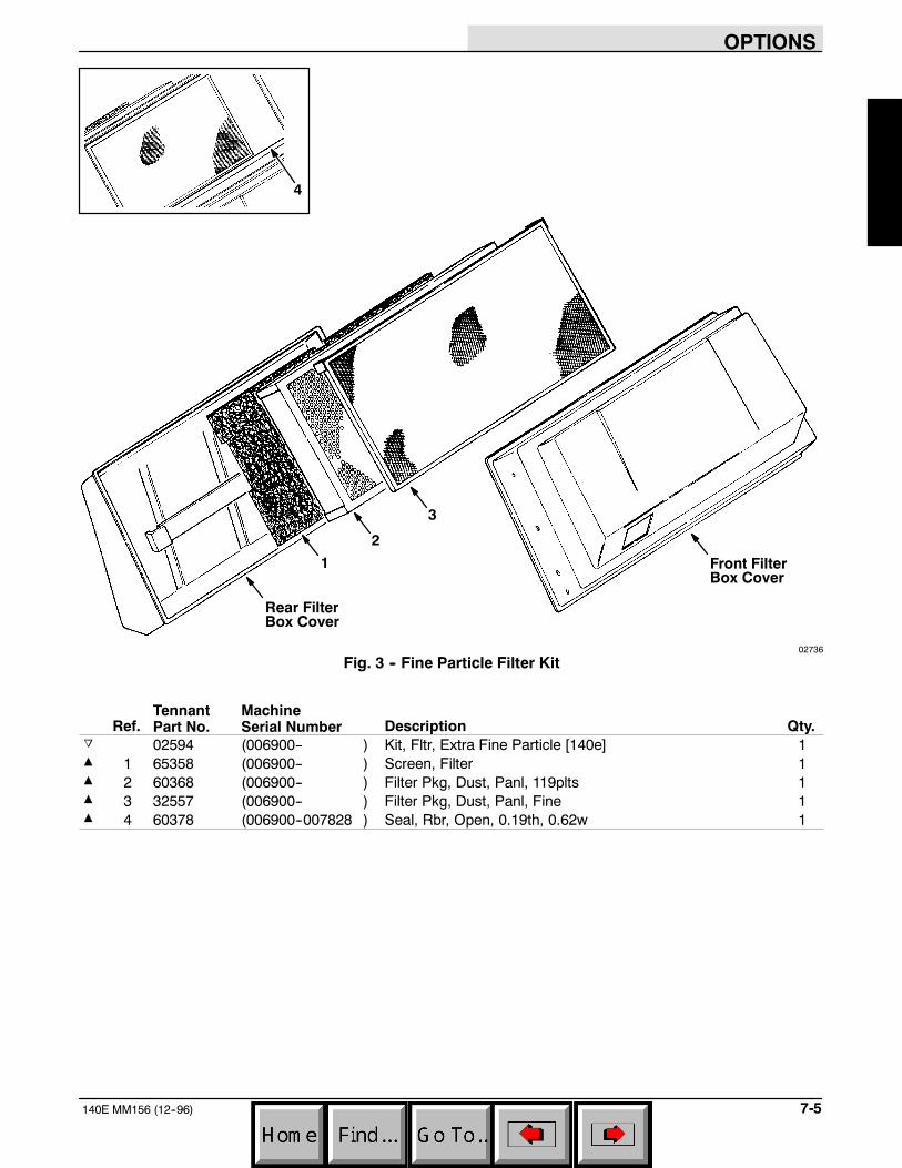
OPTIONS
7-5140E MM156 (12--96)
1
2
3
Rear FilterBox Cover
Front FilterBox Cover
4
02736
Fig. 3 -- Fine Particle Filter Kit
Ref.TennantPart No.
MachineSerial Number Description Qty.
o 02594 (006900-- ) Kit, Fltr, Extra Fine Particle [140e] 1Y 1 65358 (006900-- ) Screen, Filter 1Y 2 60368 (006900-- ) Filter Pkg, Dust, Panl, 119plts 1Y 3 32557 (006900-- ) Filter Pkg, Dust, Panl, Fine 1Y 4 60378 (006900--007828 ) Seal, Rbr, Open, 0.19th, 0.62w 1
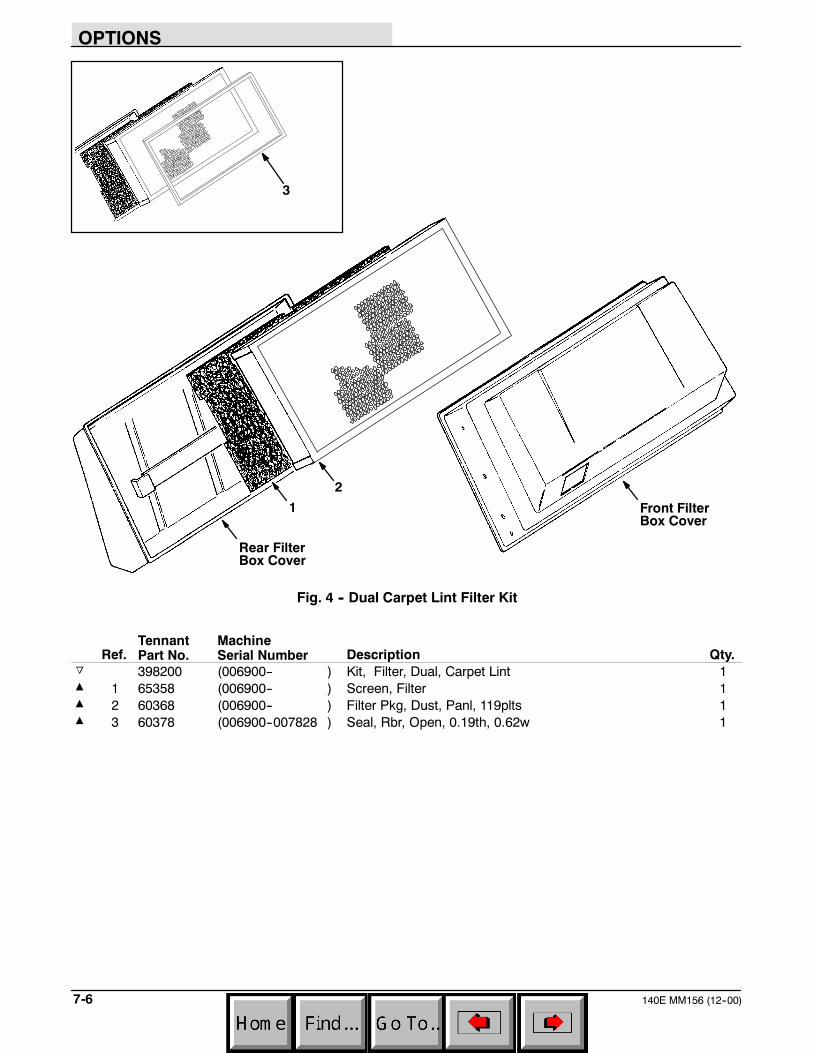
OPTIONS
140E MM156 (12--00)7-6
1
2
Rear FilterBox Cover
Front FilterBox Cover
3
Fig. 4 -- Dual Carpet Lint Filter Kit
Ref.TennantPart No.
MachineSerial Number Description Qty.
o 398200 (006900-- ) Kit, Filter, Dual, Carpet Lint 1Y 1 65358 (006900-- ) Screen, Filter 1Y 2 60368 (006900-- ) Filter Pkg, Dust, Panl, 119plts 1Y 3 60378 (006900--007828 ) Seal, Rbr, Open, 0.19th, 0.62w 1
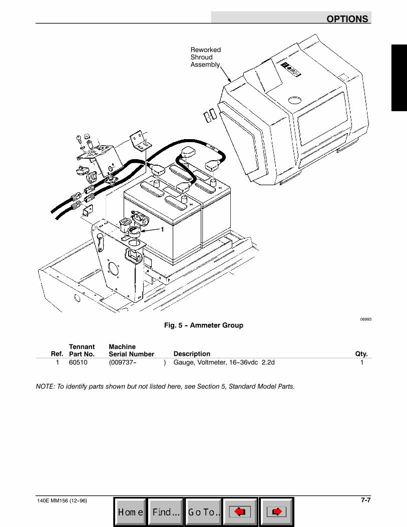
OPTIONS
7-7140E MM156 (12--96)
1
ReworkedShroudAssembly
06993
Fig. 5 -- Ammeter Group
Ref.TennantPart No.
MachineSerial Number Description Qty.
1 60510 (009737-- ) Gauge, Voltmeter, 16--36vdc 2.2d 1
NOTE: To identify parts shown but not listed here, see Section 5, Standard Model Parts.
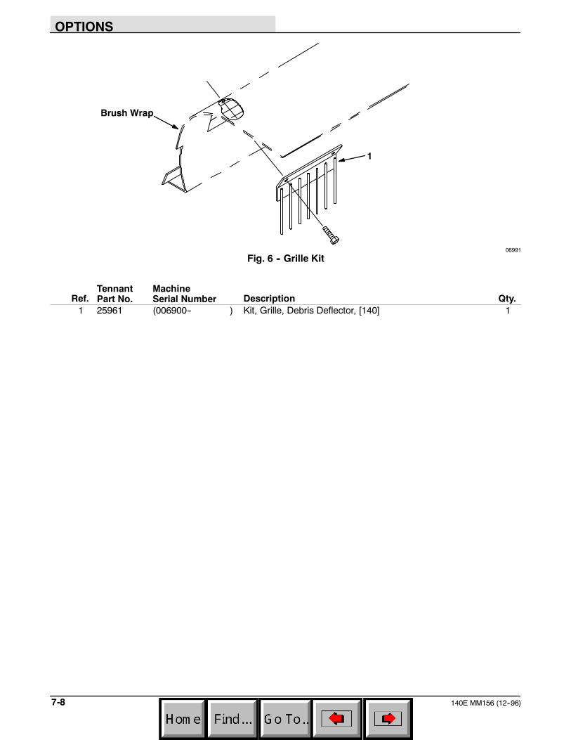
OPTIONS
140E MM156 (12--96)7-8
1
Brush Wrap
06991
Fig. 6 -- Grille Kit
Ref.TennantPart No.
MachineSerial Number Description Qty.
1 25961 (006900-- ) Kit, Grille, Debris Deflector, [140] 1
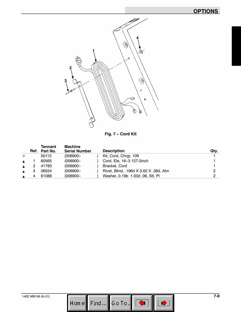
OPTIONS
7-9140E MM156 (8--01)
1
2
3
4
Fig. 7 -- Cord Kit
Ref.TennantPart No.
MachineSerial Number Description Qty.
o 50112 (006900-- ) Kit, Cord, Chrgr, 10ft 1Y 1 60565 (006900-- ) Cord, Ele, 16--3 127.0inch 1Y 2 41783 (006900-- ) Bracket, Cord 1Y 3 06524 (006900-- ) Rivet, Blind, .196d X 0.62 X .38d, Alm 2Y 4 61088 (006900-- ) Washer, 0.19b 1.00d .06, Stl, Pl 2
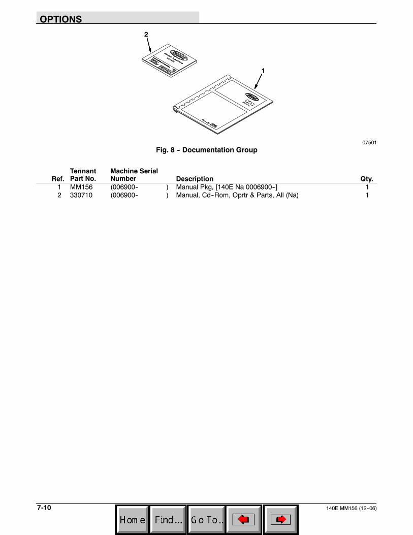
OPTIONS
140E MM156 (12--06)7-10
1
2
07501Fig. 8 -- Documentation Group
Ref.TennantPart No.
Machine SerialNumber Description Qty.
1 MM156 (006900-- ) Manual Pkg, [140E Na 0006900--] 12 330710 (006900-- ) Manual, Cd--Rom, Oprtr & Parts, All (Na) 1
CROSS REFERENCE
8-1140E MM156 (12--06)
SECTION 8CONTENTS PAGE
PART NUMBER TO PAGE NUMBER CROSS REFERENCE LIST 8-2. . . . . . . . . . . . . . . . . . . . . . . . . . . . . . . . . . . . . .PART DESCRIPTION TO PAGE NUMBER CROSS REFERENCE LIST 8-4. . . . . . . . . . . . . . . . . . . . . . . . . . . . . . . . .
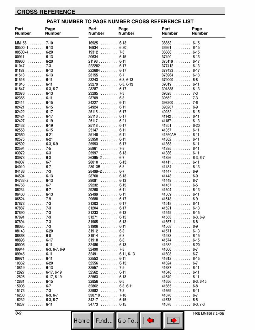
CROSS REFERENCE
140E MM156 (12--06)8-2
PART NUMBER TO PAGE NUMBER CROSS REFERENCE LISTPart PageNumber Number
MM156 7-10. . . . . . . .00500--1 6-13. . . . . . .00500--4 6-20. . . . . . .00911 6-13. . . . . . . . .00960 6-20. . . . . . . .01047 7-3. . . . . . . .01199 6-13. . . . . . . . .01513 6-13. . . . . . . .01516 6-11. . . . . . . .01845 6-11. . . . . . . .01847 6-3, 6-7. . . . . . . .02076 6-13. . . . . . . .02355 6-11. . . . . . . .02414 6-15. . . . . . . .02421 6-15. . . . . . . .02422 6-17. . . . . . . .02424 6-17. . . . . . . .02427 6-19. . . . . . . .02432 6-19. . . . . . . .02558 6-15. . . . . . . .02560 6-21. . . . . . . .02575 6-21. . . . . . . .02592 6-3, 6-9. . . . . . . .02594 7-5. . . . . . . .03972 6-3. . . . . . . .03973 6-3. . . . . . . .04007 6-7. . . . . . . .04010 6-7. . . . . . . .04188 7-3. . . . . . . .04594 6-13. . . . . . . .04733--2 6-13. . . . . . .04756 6-7. . . . . . . .06234 6-7. . . . . . . .06460 6-13. . . . . . . .06524 7-9. . . . . . . .07872 7-3. . . . . . . .07887 7-3. . . . . . . .07890 7-3. . . . . . . .07891 7-3. . . . . . . .07894 7-3. . . . . . . .08085 7-3. . . . . . . .08143 6-20. . . . . . . .08868 6-8. . . . . . . .08896 6-17. . . . . . . .09006 6-11. . . . . . . .09944 6-3, 6-7, 6-9. . . . . . . .09945 6-11. . . . . . . .09971 6-11. . . . . . . .10362 6-20. . . . . . . .10819 6-13. . . . . . . .12827 6-17, 6-19. . . . . . . .12828 6-17, 6-19. . . . . . . .12881 6-15. . . . . . . .15006 6-7. . . . . . . .15173 7-3. . . . . . . .16230 6-3, 6-7. . . . . . . .16232 6-3, 6-7. . . . . . . .16237 6-11. . . . . . . .
Part PageNumber Number
16925 6-13. . . . . . . .16934 6-20. . . . . . . .19312 7-3. . . . . . . .20634 6-15. . . . . . . .21198 6-11. . . . . . . . .222282 6-17. . . . . . . .222684 6-17. . . . . . . .23155 6-7. . . . . . . .23243 6-3, 6-13. . . . . . . .23279 6-3, 6-13. . . . . . . .23287 6-17. . . . . . . .23295 7-3. . . . . . . .23709 6-8. . . . . . . .24227 6-11. . . . . . . .24924 6-11. . . . . . . .25115 6-17. . . . . . . . .25116 6-17. . . . . . . . .25117 6-21. . . . . . . . .25118 6-17. . . . . . . . .25147 6-11. . . . . . . .25148 6-11. . . . . . . .25950 6-11. . . . . . . .25953 6-17. . . . . . . .25961 7-8. . . . . . . .25997 6-13. . . . . . . .26395--2 6-7. . . . . . .28010 6-13. . . . . . . .28013B 6-5. . . . . . .28499--2 6-7. . . . . . .28760 6-13. . . . . . . .29091 6-13. . . . . . . .29232 6-15. . . . . . . .29260 6-11. . . . . . . .29499 6-11. . . . . . . .29688 6-17. . . . . . . .31203 6-17. . . . . . . .31204 6-17. . . . . . . .31233 6-13. . . . . . . .31271 6-15. . . . . . . .31905 6-13. . . . . . . .31906 6-11. . . . . . . .31912 6-8. . . . . . . .31914 6-8. . . . . . . .31918 6-8. . . . . . . .32486 6-13. . . . . . . .32490 7-3. . . . . . . .32491 6-11, 6-13. . . . . . . .32553 6-11. . . . . . . .32556 6-15. . . . . . . .32557 7-5. . . . . . . .32562 6-11. . . . . . . .32563 6-13. . . . . . . .32856 6-5. . . . . . . .32862 6-3, 6-11. . . . . . . .32982 7-3. . . . . . . .330710 7-10. . . . . . . .34217 6-15. . . . . . . .34773 6-15. . . . . . . .
Part PageNumber Number
36658 6-15. . . . . . . .36661 6-15. . . . . . . .36666 6-15. . . . . . . .37490 6-13. . . . . . . .375119 6-17. . . . . . . .377412 6-13. . . . . . . .377433 6-17. . . . . . . .378964 6-13. . . . . . . .379000 6-8. . . . . . . .39019 6-11. . . . . . . .391838 6-13. . . . . . . .39528 7-3. . . . . . . .39562 7-3. . . . . . . .398200 7-6. . . . . . . .398207 6-9. . . . . . . .40282 6-15. . . . . . . .41142 6-11. . . . . . . . .41187 6-13. . . . . . . . .41351 6-20. . . . . . . .41357 6-11. . . . . . . .41360AM 6-11. . . . . .41362 6-11. . . . . . . .41363 6-11. . . . . . . .41385 6-11. . . . . . . .41386 6-11. . . . . . . .41396 6-3, 6-7. . . . . . . .41411 6-11. . . . . . . . .41434 6-13. . . . . . . .41447 6-9. . . . . . . .41448 6-9. . . . . . . .41449 6-7. . . . . . . .41457 6-5. . . . . . . .41504 6-13. . . . . . . .41509 6-11. . . . . . . .41513 6-9. . . . . . . .41518 6-11. . . . . . . .41521 6-13. . . . . . . .41549 6-15. . . . . . . .41563 6-3, 6-9. . . . . . . .41567--1 6-8. . . . . . .41568 6-9. . . . . . . .41571 6-13. . . . . . . .41573 6-15. . . . . . . .41574 6-15. . . . . . . .41582 6-20. . . . . . . .41600 6-7. . . . . . . .41608 6-7. . . . . . . .41612 6-15. . . . . . . .41624 6-7. . . . . . . .41637 6-11. . . . . . . .41648 6-11. . . . . . . .41649 6-11. . . . . . . .41656 6-3, 6-15. . . . . . . .41665 6-8. . . . . . . .41669 6-11. . . . . . . .41670 6-7. . . . . . . .41673 6-5. . . . . . . .41678 6-3, 7-3. . . . . . . .

CROSS REFERENCE
8-3140E MM156 (12--06)
Part PageNumber Number
41701 6-7. . . . . . . .41708 7-3. . . . . . . .41731 7-3. . . . . . . .41732 6-9. . . . . . . .41741 6-11. . . . . . . .41743 6-11. . . . . . . .41783 7-9. . . . . . . .41818 6-11. . . . . . . .41824A 6-15. . . . . . .41827 6-7. . . . . . . .41828--1 6-13. . . . . . .41829 6-8. . . . . . . .41832 6-8. . . . . . . .41837 6-3, 6-11. . . . . . . .41838 6-3, 6-15. . . . . . . .41839 6-15. . . . . . . .41840 6-3, 6-15. . . . . . . .41844 6-13. . . . . . . .41845 6-15. . . . . . . .41858 6-3, 6-15. . . . . . . .41863 6-13. . . . . . . .41864 6-11. . . . . . . .41870 6-9. . . . . . . .41871 6-13. . . . . . . .41882 6-17. . . . . . . .41883 6-17. . . . . . . .41927 7-3. . . . . . . .43942 6-7. . . . . . . .44078 6-17. . . . . . . .44939 6-15. . . . . . . .45872 6-13. . . . . . . .45962 6-17. . . . . . . .46390AM 6-13. . . . . .47037 6-3. . . . . . . .47591 6-15. . . . . . . .47751 6-11. . . . . . . .48423 7-3. . . . . . . .48451 7-3. . . . . . . .48452 7-3. . . . . . . .48635 6-13, 7-3. . . . . . . .48636 6-13, 7-3. . . . . . . .48661 6-15. . . . . . . .48662 6-15. . . . . . . .49266 6-7. . . . . . . .49566 6-11. . . . . . . .50038 6-11. . . . . . . .50040 6-13. . . . . . . .50049 6-7. . . . . . . .50050 6-7. . . . . . . .50066 6-13. . . . . . . .50090 6-13. . . . . . . .50111 6-13. . . . . . . . .50112 7-9. . . . . . . . .50116 6-7. . . . . . . . .50122 6-13. . . . . . . .50456 6-7. . . . . . . .50480 6-17. . . . . . . .50609 6-7. . . . . . . .56060 6-11. . . . . . . .57751 6-17. . . . . . . .
Part PageNumber Number
57803 6-17. . . . . . . .59455 6-3. . . . . . . .60368 7-5, 7-6. . . . . . . .60378 6-3, 7-5, 7-6. . . . . . . .60426 6-8. . . . . . . .60428 6-8. . . . . . . .60463 6-17. . . . . . . .60487 6-19. . . . . . . .60493 6-7. . . . . . . .60494 6-7. . . . . . . .60495 6-17. . . . . . . .60496 6-7. . . . . . . .60507 6-7. . . . . . . .60510 7-7. . . . . . . .60565 7-9. . . . . . . .60593 6-17. . . . . . . .61035 6-13. . . . . . . .61046 6-7. . . . . . . .61088 6-3, 6-7, 7-9. . . . . . . .61104 6-17. . . . . . . . .61106 6-17. . . . . . . . .61110 6-3, 6-7. . . . . . . . .61117 7-4. . . . . . . . .61121 7-4. . . . . . . . .61355 6-17. . . . . . . .61359 6-17. . . . . . . .61360 6-17. . . . . . . .61361 6-17. . . . . . . .61364 6-17. . . . . . . .61365 6-17. . . . . . . .61377 6-8. . . . . . . .61379 6-8. . . . . . . .61384 6-17. . . . . . . .61487 6-13. . . . . . . .62595--14 7-3. . . . . .64757 6-7. . . . . . . .65358 7-5, 7-6. . . . . . . .70004 6-7. . . . . . . .82229 6-7. . . . . . . .82747 6-17. . . . . . . .86041 6-13. . . . . . . .
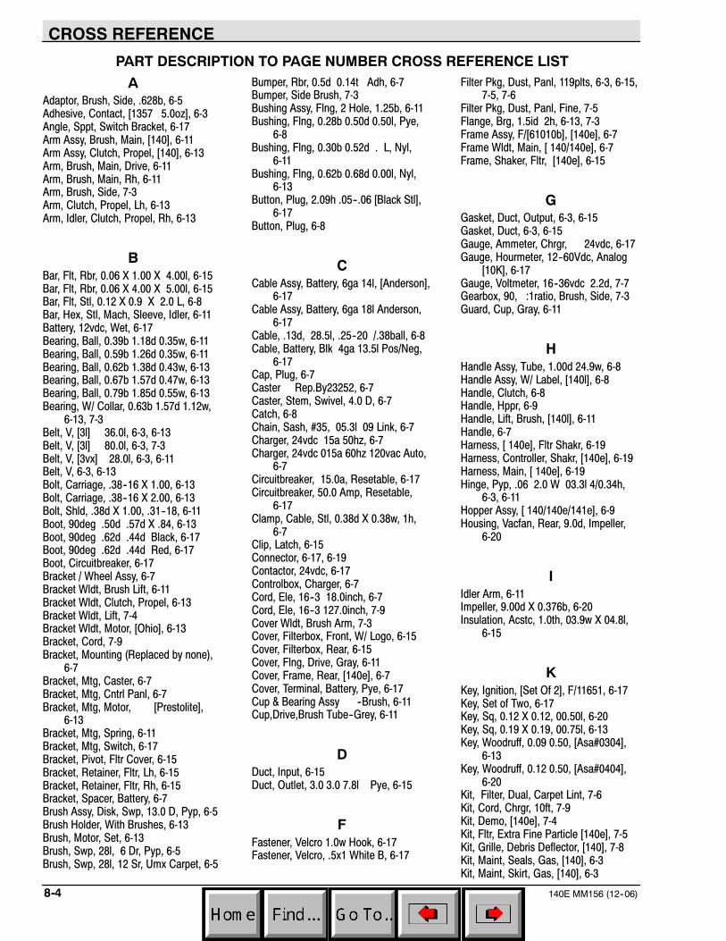
CROSS REFERENCE
140E MM156 (12--06)8-4
PART DESCRIPTION TO PAGE NUMBER CROSS REFERENCE LIST
AAdaptor, Brush, Side, .628b, 6-5Adhesive, Contact, [1357 5.0oz], 6-3Angle, Sppt, Switch Bracket, 6-17Arm Assy, Brush, Main, [140], 6-11Arm Assy, Clutch, Propel, [140], 6-13Arm, Brush, Main, Drive, 6-11Arm, Brush, Main, Rh, 6-11Arm, Brush, Side, 7-3Arm, Clutch, Propel, Lh, 6-13Arm, Idler, Clutch, Propel, Rh, 6-13
BBar, Flt, Rbr, 0.06 X 1.00 X 4.00l, 6-15Bar, Flt, Rbr, 0.06 X 4.00 X 5.00l, 6-15Bar, Flt, Stl, 0.12 X 0.9 X 2.0 L, 6-8Bar, Hex, Stl, Mach, Sleeve, Idler, 6-11Battery, 12vdc, Wet, 6-17Bearing, Ball, 0.39b 1.18d 0.35w, 6-11Bearing, Ball, 0.59b 1.26d 0.35w, 6-11Bearing, Ball, 0.62b 1.38d 0.43w, 6-13Bearing, Ball, 0.67b 1.57d 0.47w, 6-13Bearing, Ball, 0.79b 1.85d 0.55w, 6-13Bearing, W/ Collar, 0.63b 1.57d 1.12w,
6-13, 7-3Belt, V, [3l] 36.0l, 6-3, 6-13Belt, V, [3l] 80.0l, 6-3, 7-3Belt, V, [3vx] 28.0l, 6-3, 6-11Belt, V, 6-3, 6-13Bolt, Carriage, .38--16 X 1.00, 6-13Bolt, Carriage, .38--16 X 2.00, 6-13Bolt, Shld, .38d X 1.00, .31--18, 6-11Boot, 90deg .50d .57d X .84, 6-13Boot, 90deg .62d .44d Black, 6-17Boot, 90deg .62d .44d Red, 6-17Boot, Circuitbreaker, 6-17Bracket / Wheel Assy, 6-7Bracket Wldt, Brush Lift, 6-11Bracket Wldt, Clutch, Propel, 6-13Bracket Wldt, Lift, 7-4Bracket Wldt, Motor, [Ohio], 6-13Bracket, Cord, 7-9Bracket, Mounting (Replaced by none),
6-7Bracket, Mtg, Caster, 6-7Bracket, Mtg, Cntrl Panl, 6-7Bracket, Mtg, Motor, [Prestolite],
6-13Bracket, Mtg, Spring, 6-11Bracket, Mtg, Switch, 6-17Bracket, Pivot, Fltr Cover, 6-15Bracket, Retainer, Fltr, Lh, 6-15Bracket, Retainer, Fltr, Rh, 6-15Bracket, Spacer, Battery, 6-7Brush Assy, Disk, Swp, 13.0 D, Pyp, 6-5Brush Holder, With Brushes, 6-13Brush, Motor, Set, 6-13Brush, Swp, 28l, 6 Dr, Pyp, 6-5Brush, Swp, 28l, 12 Sr, Umx Carpet, 6-5
Bumper, Rbr, 0.5d 0.14t Adh, 6-7Bumper, Side Brush, 7-3Bushing Assy, Flng, 2 Hole, 1.25b, 6-11Bushing, Flng, 0.28b 0.50d 0.50l, Pye,
6-8Bushing, Flng, 0.30b 0.52d . L, Nyl,
6-11Bushing, Flng, 0.62b 0.68d 0.00l, Nyl,
6-13Button, Plug, 2.09h .05--.06 [Black Stl],
6-17Button, Plug, 6-8
CCable Assy, Battery, 6ga 14l, [Anderson],
6-17Cable Assy, Battery, 6ga 18l Anderson,
6-17Cable, .13d, 28.5l, .25--20 /.38ball, 6-8Cable, Battery, Blk 4ga 13.5l Pos/Neg,
6-17Cap, Plug, 6-7Caster Rep.By23252, 6-7Caster, Stem, Swivel, 4.0 D, 6-7Catch, 6-8Chain, Sash, #35, 05.3l 09 Link, 6-7Charger, 24vdc 15a 50hz, 6-7Charger, 24vdc 015a 60hz 120vac Auto,
6-7Circuitbreaker, 15.0a, Resetable, 6-17Circuitbreaker, 50.0 Amp, Resetable,
6-17Clamp, Cable, Stl, 0.38d X 0.38w, 1h,
6-7Clip, Latch, 6-15Connector, 6-17, 6-19Contactor, 24vdc, 6-17Controlbox, Charger, 6-7Cord, Ele, 16--3 18.0inch, 6-7Cord, Ele, 16--3 127.0inch, 7-9Cover Wldt, Brush Arm, 7-3Cover, Filterbox, Front, W/ Logo, 6-15Cover, Filterbox, Rear, 6-15Cover, Flng, Drive, Gray, 6-11Cover, Frame, Rear, [140e], 6-7Cover, Terminal, Battery, Pye, 6-17Cup & Bearing Assy --Brush, 6-11Cup,Drive,Brush Tube--Grey, 6-11
DDuct, Input, 6-15Duct, Outlet, 3.0 3.0 7.8l Pye, 6-15
FFastener, Velcro 1.0w Hook, 6-17Fastener, Velcro, .5x1 White B, 6-17
Filter Pkg, Dust, Panl, 119plts, 6-3, 6-15,7-5, 7-6
Filter Pkg, Dust, Panl, Fine, 7-5Flange, Brg, 1.5id 2h, 6-13, 7-3Frame Assy, F/[61010b], [140e], 6-7Frame Wldt, Main, [ 140/140e], 6-7Frame, Shaker, Fltr, [140e], 6-15
GGasket, Duct, Output, 6-3, 6-15Gasket, Duct, 6-3, 6-15Gauge, Ammeter, Chrgr, 24vdc, 6-17Gauge, Hourmeter, 12--60Vdc, Analog
[10K], 6-17Gauge, Voltmeter, 16--36vdc 2.2d, 7-7Gearbox, 90, :1ratio, Brush, Side, 7-3Guard, Cup, Gray, 6-11
HHandle Assy, Tube, 1.00d 24.9w, 6-8Handle Assy, W/ Label, [140l], 6-8Handle, Clutch, 6-8Handle, Hppr, 6-9Handle, Lift, Brush, [140l], 6-11Handle, 6-7Harness, [ 140e], Fltr Shakr, 6-19Harness, Controller, Shakr, [140e], 6-19Harness, Main, [ 140e], 6-19Hinge, Pyp, .06 2.0 W 03.3l 4/0.34h,
6-3, 6-11Hopper Assy, [ 140/140e/141e], 6-9Housing, Vacfan, Rear, 9.0d, Impeller,
6-20
IIdler Arm, 6-11Impeller, 9.00d X 0.376b, 6-20Insulation, Acstc, 1.0th, 03.9w X 04.8l,
6-15
KKey, Ignition, [Set Of 2], F/11651, 6-17Key, Set of Two, 6-17Key, Sq, 0.12 X 0.12, 00.50l, 6-20Key, Sq, 0.19 X 0.19, 00.75l, 6-13Key, Woodruff, 0.09 0.50, [Asa#0304],
6-13Key, Woodruff, 0.12 0.50, [Asa#0404],
6-20Kit, Filter, Dual, Carpet Lint, 7-6Kit, Cord, Chrgr, 10ft, 7-9Kit, Demo, [140e], 7-4Kit, Fltr, Extra Fine Particle [140e], 7-5Kit, Grille, Debris Deflector, [140], 7-8Kit, Maint, Seals, Gas, [140], 6-3Kit, Maint, Skirt, Gas, [140], 6-3
CROSS REFERENCE
8-5140E MM156 (12--06)
Kit, Replmt, Arm, Clutch, F/ 41611, 6-13Kit, Replmt, Battery Harness, 6-17Kit, Replmt, Battery,Wet F/10146, 6-17Kit, Replmt, Bearing,F/41646, 6-13Kit, Replmt, Bracket, 6-17Kit, Replmt, Cable Guide, Clutch, 6-8Kit, Replmt, Chrgr, F/ 50708, 6-7Kit, Replmt, Chrgr, F/ 50709, 6-7Kit, Replmt, Frame, F/ 48625--1, 6-8Kit, Replmt, Frame, F/ 09003, 6-8Kit, Replmt, Handle / Bracket, 6-11Kit, Replmt, Idler Arm, F/ 41817, 6-11Kit, Replmt, Idler, F/ [41819&47], 6-11Kit, Replmt, Idler, F/31230/1/2, 6-13Kit, Replmt, Label, Complt, [140e], 6-21Kit, Replmt, Shaft, F/39571, 6-13Knob Rep.Bynone, 6-17
LLabel, Numerals, [ 140/E] Black, 6-21Label, Opertnl, Instmt Panl,[140], 6-21
MManual Pkg, [140E Na 0006900--], 7-10Manual, Cd--Rom, Oprtr & Parts, All
(Na), 7-10Molding, Trim, .08--.11 39.20, 7-3Molding, Trim, .08--.11 44.00, 7-3Molding, Trim, Rubber, .06 1.4l, 6-9Motor Rep. By 50091, 6-13Motor, Ele, 36vdc Hp Shaker, 6-15Motor, Ele, .8hp, 6-13Motor, Ele, 24Vdc 0.75Hp 2100Rpm
28.0A, 6-13
NNut, Hex, Jam, .38--16, Lh, 7-3Nut, Hex, Std, M10X1.5, 7-3Nut, Isolator, .25--20 #1/4--S, 6-15Nut, Speed, Retainer, .25--20, 6-8Nut, U, .25--20, 6-3, 6-7
PPanel Wldt, Backing, Vacfan, 6-20Panel, Brush, 6-7Panel, Fan, Spprt, Rework, [60495], 6-17Parts Unique, Hd Bmpr, Lpg, Ml--D, 6-17Pin, Clevis, 0.25 D X 1.25l, 7-3Pin, Clevis, 0.37 D X 0.62l, 6-13Pin, Clevis, 0.37 D X 0.75l, 6-11Pin, Hair Cotter, 0.31 D .058 Wir, 7-3Plate Rep.Bynone, 6-11Plate, Mtg, Bracket, 7-3Plate, 6-11
RReplmt.Parts Pkg 140e, 6-3Retainer Rep.By61381, 6-15Retainer, Seal, W/ Label, Rear, 6-9Retainer, Skirt, Hppr, Rear,, 6-9Retainer, 6-15, 7-3Ring, Retaining, Ext, 0.59d, Basic, 6-11Ring, Retaining, Int, 1.38d, Basic, 6-13Rivet, Blind, .188D X 0.45 X .38D, Stl,
6-9Rivet, Blind, .188d X 0.58 X .38d, Stl, 6-8Rivet, Blind, .196d X 0.62 X .38d, Alm,
7-9Rod, Thrd, Full, .31--18 05.7l, 6-11Rod, 6-8
SScreen, Filter, 7-5, 7-6Screw, Btn, .25--20 X 0.62, Nl, 7-3Screw, Hex, .25--20X2.00, 5, 7-3Screw, Hex, .38--16 X 1.00, Lh, 6-13Screw, Hex, .38--16 X 1.25, 5, 6-11Screw, Hex, .50--13 X 6.50, 2, Unpl, 6-13Screw, Set, #10--24 X 0.25, Nl, 6-15Seal, Foam, Rbr, .38 0.75w 94.0l, 6-3,
6-15Seal, Foam, Rbr, .50 0.75w 03.0l, 6-11Seal, Rbr, Open, 0.19th, 0.62w 04.6l,
6-3, 6-9Seal, Rbr, Open, 0.19th, 0.62w, 6-3, 7-5,
7-6Shaft, Cntrl, Clutch, 6-13Shaft, Drive, Brush, Side, 7-3Shaft, 6-11, 6-20Shaker, Filter, Dust, 6-15Sheave, [3l], 1grv, 01.4pd .38--16, 7-3Sheave, [3l], 1grv, 01.6pd 0.62b, 6-13Sheave, [3l], 1grv, 01.8pd 0.62b, 6-13Sheave, [3l], 1grv, 02.9pd .38--16, 7-3Sheave, [3l], 1grv, 06.4pd 0.38b, 6-13Sheave, [3v], 1grv, 02.2pd 0.38b, 6-13Sheave, [3v], 1grv, 03.0pd 0.38brg, 6-11Sheave, [3v], 1grv, 03.5pd 0.38b, 6-11Sheave, Flat, 1.8d 1.38w 0.67b, 6-13Shield, Hppr, 6-9Shroud, 6-17Skirt, .06th, 10.00w 30.00l, 06/0.31h,
6-3, 6-9Skirt, 6-3, 6-7, 6-9Sleeve, 6-7, 6-11, 6-13, 6-15Spacer, 6-20Spring, Cmpr, 0.72od .55wir 3.0l, 6-11Spring, Extn, 0.75od X 0.06wir, 5.3l,
6-11Spring, Extn, 0.75od X 0.11wir, 4.5l,
6-11Strainrelief, 6-15Strap, 6-15Strip, Stl, 0.07th X 00.90w, 03.30l, 6-11Strip, 6-7Support Wldt, Fan, 6-17
Switch Rep.By374227, 6-17Switch Rep.By70089, 6-17Switch, Key, 12Vdc A Spdt, 6-17Switch, 6-17
TTerminal, Qdc, [.25f, Ins ,14], 6-7Terminal, Qdc, [.25m, Insf,10], 6-7Terminal, Qdc, [.25m, Inss, ], 6-7Tie, Cable, Nyl, 07.3l .19w 1.8 Max D,
6-7Tire Assy, Solid, 08.0x2.0 1.37b, 6-13Tire Assy, Solid, 08.0x2.0 , W/ Brg, 6-13Tray, 6-7Tube, Steel, 6-13
WWasher, 0.19b 1.00d .06, Stl, Pl, 6-3,
6-7, 7-9Washer, 0.28b 0.62d .06, Nyl, 6-11Washer, 0.38b 0.56d .03, Stl, 6-11Washer, Belleville, .38, 6-13Washer, Flat, 0.25 Std, 7-3Washer, Flat, 6-11Washer, Flt, .31 Std, 6-11, 6-13Washer, Flt, .50 Sae, 6-13Washer, Lock, Int, .25, 7-3Washer, Lock, Int--Ext, .38, 6-11Washer, 6-11Weight, Eccentric, 6-15Wheel Assy, 4.0d 0.81w, 7-3Wheel, 1.6d 0.72w 0.21b, 6-3, 6-7Wheel, 4.0d 0.81w 0.25b, 7-3Wire, 06ga 13.5l Blk .38ring /.31ring,
6-17Wire, 06ga 14.5l Blk .31ring /Anderson,
6-17Wire, 06ga 18.5l Red .38ring
/Anderson, 6-17Wire, 6-7

CROSS REFERENCE
140E MM156 (12--06)8-6

We Need Your Help...As part of Tennant’s Zero Defects Program, we want to know about errors you havefound or suggestions you may have regarding our machine manuals. If you find anerror or have a suggestion, please complete this postage-paid form and mail it to us.Thank you for helping us make zero defects a way of life at Tennant.
Manual No. Rev. No. Publish Date PageMachine - Report Error - Suggestion
Name Date
Customer Number
Company
Address
City/State/Zip Code
Tapehere Foldalongdottedlines
NOPOSTAGENECESSARY
IFMAILEDINTHE
UNITEDSATES
BUSINESSREPLYMAIL FIRSTCLASSMAILPERMITNO.94MINNEAPOLIS,MN
POSTAGEWILLBEPAIDBYADDRESSEE
TechnicalPublications#15701NorthLilacDriveP.O.Box1452Minneapolis,MN55440--9947
TENNANTCOMPANY

We Need Your Help...As part of Tennant’s Zero Defects Program, we want to know about errors you havefound or suggestions you may have regarding our machine manuals. If you find anerror or have a suggestion, please complete this postage-paid form and mail it to us.Thank you for helping us make zero defects a way of life at Tennant.
Manual No. Rev. No. Publish Date PageMachine - Report Error - Suggestion
Name Date
Customer Number
Company
Address
City/State/Zip Code

Tapehere Foldalongdottedlines
NOPOSTAGENECESSARY
IFMAILEDINTHE
UNITEDSATES
BUSINESSREPLYMAIL FIRSTCLASSMAILPERMITNO.94MINNEAPOLIS,MN
POSTAGEWILLBEPAIDBYADDRESSEE
TechnicalPublications#15701NorthLilacDriveP.O.Box1452Minneapolis,MN55440--9947
TENNANTCOMPANY