Embed Size (px)
Citation preview

New Hampshire Department of Transportation
Effective June 1, 2017
2017CAD/D Procedures
& Requirements


NHDOT CAD/D Procedures and Requirements
June 2017 i Table of Contents
PART I – GENERAL INTRODUCTION ........................................................................... 1
Disclaimer ..................................................................................................................................................................... 1
About the Cover ........................................................................................................................................................... 1
Revision Summary ....................................................................................................................................................... 2 June 2017 ................................................................................................................................................................... 2 April 2012 .................................................................................................................................................................. 2
Introduction ................................................................................................................................................................. 4
Current NHDOT Software Versions .......................................................................................................................... 5 Major Software and Current Production Versions .................................................................................................... 5 Future Upgrades ........................................................................................................................................................ 5
PART II – GENERAL CAD/D INFORMATION ............................................................... 7
Documentation ............................................................................................................................................................. 7
Survey Datum .............................................................................................................................................................. 7
Project Journal Files ................................................................................................................................................... 7 Project Journal Guidelines ......................................................................................................................................... 7 Sample CAD/D Project Journal .................................................................................................................................. 8
Directory Structure ................................................................................................................................................... 13
PART III – MICROSTATION ......................................................................................... 15
MicroStation Workspace .......................................................................................................................................... 15
File Naming ................................................................................................................................................................ 15
Level Assignments and Symbology .......................................................................................................................... 15
Reference File Attachments ...................................................................................................................................... 16
Seed Files .................................................................................................................................................................... 16 Imperial Seed Files (2D & 3D) .................................................................................................................................. 17
Fonts ........................................................................................................................................................................... 18
Text Height and Spacing ........................................................................................................................................... 19
Text Styles .................................................................................................................................................................. 19
Linestyles .................................................................................................................................................................... 20 NHDOT Custom Linestyle Resource Files ................................................................................................................. 20 True Size Linestyles .................................................................................................................................................. 20 Scaled Linestyles ...................................................................................................................................................... 21

NHDOT CAD/D Procedures and Requirements
Table of Contents ii June 2017
Custom Linestyle Scaling Charts .............................................................................................................................. 21 Linestyles Created at 1:1 ......................................................................................................................................... 22
Color Table ................................................................................................................................................................. 22
Cross Hatching ........................................................................................................................................................... 22
Cell Files ..................................................................................................................................................................... 24
Dimensioning .............................................................................................................................................................. 25
Plotting........................................................................................................................................................................ 25
Print Organizer .......................................................................................................................................................... 25
Pen Tables .................................................................................................................................................................. 26
PART IV – OPENROADS ............................................................................................. 27
Introduction ............................................................................................................................................................... 27
File Naming ................................................................................................................................................................ 27
Seed Files .................................................................................................................................................................... 27
OpenRoads Drawing Names ..................................................................................................................................... 27
Template Files ............................................................................................................................................................ 27
OpenRoads Cell Files & Linestyles .......................................................................................................................... 28
Civil Cells ................................................................................................................................................................... 28
MX-Specific Notes ..................................................................................................................................................... 28 MX File Naming ...................................................................................................................................................... 28 MX Model Naming ................................................................................................................................................. 29 MX String Labeling ................................................................................................................................................. 29 MX Style Sets .......................................................................................................................................................... 29 MX Feature Sets ...................................................................................................................................................... 29 Cross-Section Settings Files .................................................................................................................................... 29 Add-Ins .................................................................................................................................................................... 30
PART V – PROCEDURES ............................................................................................ 31
Introduction ............................................................................................................................................................... 31
Exchanging Right-of-Way Data ............................................................................................................................... 31
Legacy Alignments .................................................................................................................................................... 32
Using OpenRoads Templates .................................................................................................................................... 32
Roll Plans .................................................................................................................................................................... 32

NHDOT CAD/D Procedures and Requirements
June 2017 iii Table of Contents
Cut Sheets ................................................................................................................................................................... 33
Cross-Section Drawings ............................................................................................................................................ 33
Bridge Detail Sheets ................................................................................................................................................... 33
PART VI – OTHER PROJECT DATA ........................................................................... 35
Drawing Quality Assurance / Quality Control ........................................................................................................ 35
PART VII - ENGINEERING CONSULTANT DELIVERABLE REQUIREMENTS ......... 37
Overview ..................................................................................................................................................................... 37
File Format And Delivery ......................................................................................................................................... 37 Requirements For Submitting Electronic Data To NHDOT ...................................................................................... 37 Data Submission ...................................................................................................................................................... 38 Intermediate Submissions ....................................................................................................................................... 38 Deviation From Format ............................................................................................................................................ 38 MicroStation Only Deliverable ................................................................................................................................. 39 Record of Design as Submitted (Final Design Consultants Only) ............................................................................. 39 File Conversion ........................................................................................................................................................ 39
Initiating a Design Project ........................................................................................................................................ 40
Interim Project Deliverables ..................................................................................................................................... 40
Project Completion .................................................................................................................................................... 41 CAD/D File Information ........................................................................................................................................... 41 Projects Designed using InRoads ............................................................................................................................. 44 Specialized Development by Design Consultants .................................................................................................... 45
NHDOT Resources Available for Consultants ........................................................................................................ 45
PART VIII - APPENDIX ................................................................................................. 47
Appendix A - MicroStation Drawing Names........................................................................................................... 47
Appendix B - Level Mapping Convention ............................................................................................................... 47
Appendix C - NHDOT Custom Linestyles & Font ................................................................................................. 49
Appendix D – MX Model Naming Convention ....................................................................................................... 53
Appendix E – Civil Data Transfer Formats ............................................................................................................ 53 LandXML .................................................................................................................................................................. 53
Appendix F – Construction Reports ....................................................................................................................... 55 Sample OpenRoads Alignment Report (COGO Style) .............................................................................................. 55 Sample OpenRoads Alignment Report (Coordinates) ............................................................................................. 56
Appendix G – Cross Section Set Labels ................................................................................................................... 57

June 2017 1 Part I – General Introduction
PART I – GENERAL INTRODUCTION
DISCLAIMER
The procedures described in this document are for reference only. This information is provided on an
"as is" basis. The material contained is provided without warranty or liability of any kind to the New
Hampshire Department of Transportation (NHDOT).
Updating this manual is intended to be a continuous process. As technology evolves, policies change,
and process improvements are discovered, this document will be updated to reflect those changes.
As with any documentation, improvements can and should be made. Any additions, suggestions or
comments for improvement are encouraged. This documentation is not meant to be a complete
instructional document. The intent is to provide guidelines that, if followed, will result in better quality
and consistency for electronic plans and documents.
This manual, in its entirety, may be freely copied and distributed for the purpose of providing a
consistent guide to the Computer Aided Design & Drafting (CAD/D) requirements of the New Hampshire
Department of Transportation. Copies of this manual along with CAD/D resource files (style libraries,
naming conventions, etc.) can be downloaded at https://www.nh.gov/dot/cadd/downloads/index.htm.
Any recommendations for improvements to this documentation are welcome. Any errors found should
be brought to the attention of the CAD/D Staff so corrections can be made. For additional information
or detailed explanations of the standards described within this document, contact:
CAD/D Support and Development
Bureau of Highway Design
New Hampshire Department of Transportation
PO Box 483
Concord, NH 03302-0483
NHDOT CAD/D Website: https://www.nh.gov/dot/cadd/
E-mail: [email protected]
Tel: 603-271-2171
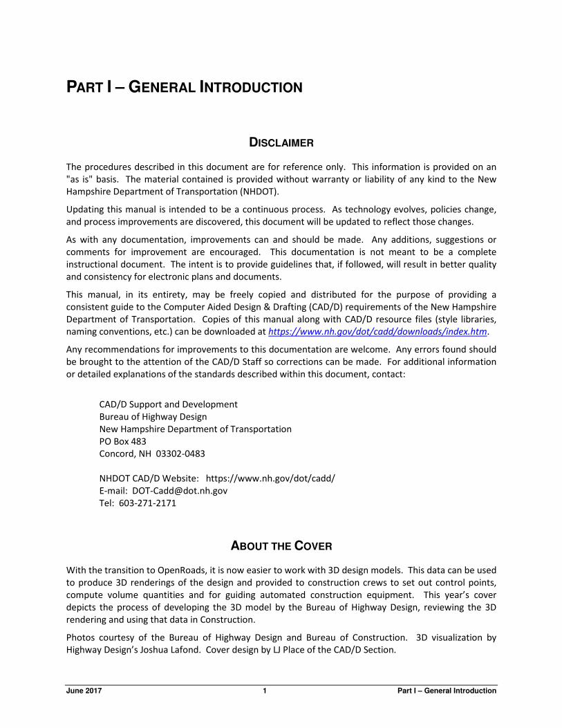
ABOUT THE COVER
With the transition to OpenRoads, it is now easier to work with 3D design models. This data can be used
to produce 3D renderings of the design and provided to construction crews to set out control points,
compute volume quantities and for guiding automated construction equipment. This year’s cover
depicts the process of developing the 3D model by the Bureau of Highway Design, reviewing the 3D
rendering and using that data in Construction.
Photos courtesy of the Bureau of Highway Design and Bureau of Construction. 3D visualization by
Highway Design’s Joshua Lafond. Cover design by LJ Place of the CAD/D Section.

NHDOT CAD/D Procedures and Requirements
Part I – General Introduction 2 June 2017
REVISION SUMMARY
JUNE 2017
Part I– General Introduction
• Updated software versions.
Part II– General CAD/D Information
• Revisions to Project Journal File to reflect transition from MX design to OpenRoads.
• Updates to project directory structure.
Part III– MicroStation
• Seed file information changed to reflect transition towards US Survey Foot files plus additional
information of Geographic Coordinate Systems.
• Information about the NHDOT pen table has been updated.
Part IV– OpenRoads
• Section renamed from Part IV - MX.
• Rewrite to section to reflect transition from MX design to OpenRoads.
Part VII - Engineering Consultant Deliverable Requirements
• Section significantly modified to update for transition to OpenRoads design.
• Included information about Item 670.822 - GNSS Construction Inspection Equipment
Appendix
• Linestyle charts in Appendix C have been updated.
• Appendix D – MX Model Naming Convention has been removed.
APRIL 2012
Part I– General Introduction
• New software versions.
Part II– General CAD/D Information
• The project directory structure was modified to separate MX data from contract plan drawing data.
Part III– MicroStation
• Updates to cell file listing.
• Seed file information now includes geographic coordinate system being used.
• Information about the NHDOT pen table has been updated.
Part V – Procedures
• The process for creating cut sheets has been modified along with the sheet naming convention.

NHDOT CAD/D Procedures and Requirements
June 2017 3 Part I – General Introduction
Part VI – Other Project Data
• Notes on QA_Input and other GDM programs have been replaced by descriptions of task menus.
Appendix
• Changes to MicroStation drawing names in Appendix A.
• Linestyle charts have been updated in Appendix C.
• Appendix D (MX model names) has been updated to reflect current practices.
• MX String label lists have been updated.

NHDOT CAD/D Procedures and Requirements
Part I – General Introduction 4 June 2017
INTRODUCTION
This document contains the New Hampshire Department of Transportation’s (NHDOT) specifications for
electronic (computer) data as it relates to engineering design projects. It explains the minimum
requirements that must be met for all Computer Aided Design & Drafting (CAD/D) data produced by and
for the New Hampshire Department of Transportation. This is to ensure that CAD/D files can be used by
the entire project team throughout all phases of project development. While the requirements
contained herein provide a basis for uniform CAD/D practice for NHDOT projects, precise rules that
would apply to all possible situations that may arise are not possible to describe. Situations may exist
where these standards will not apply. If variances from the "CAD/D PROCEDURES AND REQUIREMENTS" are
necessary for a project, they must be approved in writing by the NHDOT Project Manager and
documented in the Project Journal File as defined herein. The creation of MicroStation drawings and/or
levels for features that are not described in this document shall be documented in the Project Journal
File. The creation of MX models that are not described in this document shall be documented in the
Project Journal File.
As a minimum, NHDOT Design staff and engineering consultants are expected to adhere to the
standards that were in force at the time the contract was initiated. Although not required, following the
latest standard is recommended whenever feasible.
In addition to the traditional hardcopy delivery items, NHDOT requires supplementary electronic data
delivery items. This data shall be submitted in the formats specified in Part VII - Engineering Consultant
Deliverable Requirements. In general, design data and Digital Terrain Model (DTM) data is to be
provided in the OpenRoads DGN or LandXML formats, and graphical data is to be provided in
MicroStation's .DGN drawing format. Organizations wishing to perform professional engineering
services for NHDOT are required to deliver electronic data as specified by this document. This
specification also requires organizations to accept and utilize pertinent electronic input data as provided
by NHDOT.
These electronic delivery items DO NOT replace any hardcopy delivery items.
This document is published as an update to the "CAD/D PROCEDURES AND REQUIREMENTS" document dated
April 2012 and supersedes all CAD/D standards previously published. Sections which have changed from
the previous version are denoted by the vertical line in the right margin.
Trademarks
Microsoft and Windows are registered trademarks of Microsoft Corporation.
MicroStation, OpenRoads, MDL, InRoads, GEOPAK, MX, and MXROAD are registered trademarks of
Bentley Systems, Inc.

NHDOT CAD/D Procedures and Requirements
June 2017 5 Part I – General Introduction
CURRENT NHDOT SOFTWARE VERSIONS
NHDOT desires to stay current with state of the art trends in the market, however, budget constraints,
statewide implementation, impact on users, and providing support for the new features must be
considered prior to any change.
As NHDOT makes a change that results in modifying electronic procedures, the "CAD/D PROCEDURES AND
REQUIREMENTS" will be updated where necessary to reflect the change. A list of the modifications will be
found in the revision summary. As a rule, until documentation is modified, deviation from the current
dated requirements must be approved by the Project Manager.
MAJOR SOFTWARE AND CURRENT PRODUCTION VERSIONS
1. MicroStation V8i (SELECTseries 4) (version 08.11.09.832)
2. MX V8i (SELECTseries 4) (version 08.11.09.878)
3. Microsoft Office 2010 products with Access 2003
FUTURE UPGRADES
A newer version of MicroStation (the CONNECT Edition) is presently available and will be tested in the
future to determine when or if NHDOT will upgrade to that version.
OpenRoads Designer, Bentley’s replacement for the civil design products – MX, InRoads and Geopak –
will be tested and eventually replace MX.

NHDOT CAD/D Procedures and Requirements
June 2017 7 Part II – General CAD/D Information
PART II – GENERAL CAD/D INFORMATION
DOCUMENTATION
Documentation of NHDOT CAD/D practices and procedures can be found on the Internet at
https://www.nh.gov/dot/cadd/. Summaries of selected procedures will be found in PART V – PROCEDURES
beginning on page 31.
SURVEY DATUM
For NHDOT projects, the horizontal and vertical coordinate systems can vary from project to project
depending on a variety of conditions. New projects will tend to have a vertical datum based on NAVD88
with the horizontal coordinates using NAD83/2011F. However, the designer should always check with
the Survey group to confirm these details so the CAD/D drawings can be set up correctly.
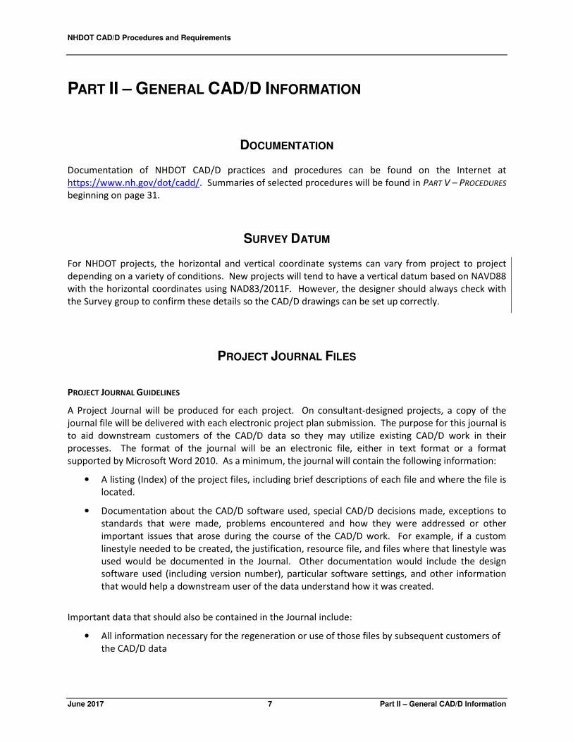
PROJECT JOURNAL FILES
PROJECT JOURNAL GUIDELINES
A Project Journal will be produced for each project. On consultant-designed projects, a copy of the
journal file will be delivered with each electronic project plan submission. The purpose for this journal is
to aid downstream customers of the CAD/D data so they may utilize existing CAD/D work in their
processes. The format of the journal will be an electronic file, either in text format or a format
supported by Microsoft Word 2010. As a minimum, the journal will contain the following information:
• A listing (Index) of the project files, including brief descriptions of each file and where the file is
located.
• Documentation about the CAD/D software used, special CAD/D decisions made, exceptions to
standards that were made, problems encountered and how they were addressed or other
important issues that arose during the course of the CAD/D work. For example, if a custom
linestyle needed to be created, the justification, resource file, and files where that linestyle was
used would be documented in the Journal. Other documentation would include the design
software used (including version number), particular software settings, and other information
that would help a downstream user of the data understand how it was created.
Important data that should also be contained in the Journal include:
• All information necessary for the regeneration or use of those files by subsequent customers of
the CAD/D data
NHDOT CAD/D Procedures and Requirements
Part II – General CAD/D Information 8 June 2017
• Document the design data, controlling alignment and profile names and geometry input/output
files, relevant survey information, cross sections and the methodology used to obtain the final
geometric controls in the CAD/D product.
NHDOT has not established a specific format for the Journal file. The sample file shown on the following
pages should be used as a guideline for the type of information to be included and format that is
expected.
The project journal must be kept up to date as the CAD/D design work progresses and be delivered with
the project on the preferred media for archival purposes.
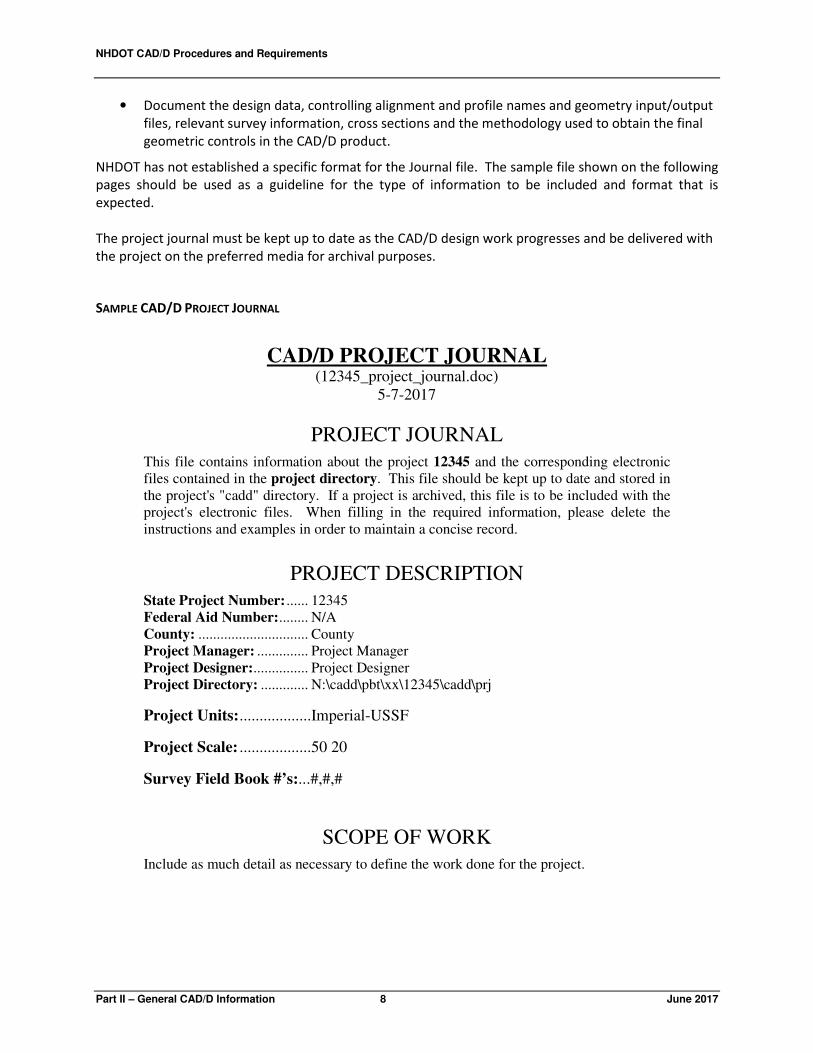
SAMPLE CAD/D PROJECT JOURNAL
CAD/D PROJECT JOURNAL (12345_project_journal.doc)
5-7-2017
PROJECT JOURNAL
This file contains information about the project 12345 and the corresponding electronic
files contained in the project directory. This file should be kept up to date and stored in
the project's "cadd" directory. If a project is archived, this file is to be included with the
project's electronic files. When filling in the required information, please delete the
instructions and examples in order to maintain a concise record.
PROJECT DESCRIPTION
State Project Number: ...... 12345
Federal Aid Number: ........ N/A
County: .............................. County
Project Manager: .............. Project Manager
Project Designer: ............... Project Designer
Project Directory: ............. N:\cadd\pbt\xx\12345\cadd\prj
Project Units: ..................Imperial-USSF
Project Scale: ..................50 20
Survey Field Book #’s:...#,#,#
SCOPE OF WORK
Include as much detail as necessary to define the work done for the project.

NHDOT CAD/D Procedures and Requirements
June 2017 9 Part II – General CAD/D Information
PROJECT FILES
List any drawing files that do not fit into the standard naming convention. Include a brief description of
the data contained in each one.
MICROSTATION FILE INFORMATION
Seed File(s) Used for this Project: nhseedf2-ussf.dgn nhseedft-ussf.dgn nhseed-or-ussf.dgn
Non-Standard Drawings
List any drawings that are not on the standard naming convention list with a brief description of
each one's contents.
Plot Information
List information about Print Organizer specifications, pen tables, or other features used to
generate the plot files.
OPENROADS
Template File name – 12345NHDOT-IMP.itl
Project XIN file if not standard -
Project Features DGNLIB if used –
Project Civil Cell DGNLIB if Used -
Roadway – "Road Name"
Alignment Information
DGN Name ..................................12345-Geometry.dgn
Horiz. Alignment Feature Name ..MCxM Rte 16
Vert. Alignment Feature Name ....MCxM Rte 16 Prof
Existing Feature Name MCxM Sect Exist Elev
Associated MX Model .................GEOMETRY
Associated MX String ..................MCxM
Old Ground Profile String ............OCxM
Reports
Horizontal Review ASCII- ....12345-MCxM-Hor-Review.txt
Horiz. Interval Points XYZ ....12345-MCxM-Hor-XYZ.xls
Vertical Review ASCII ..........12345-MCxM-Vert-Review.txt
LandXML ..............................12345-MCxM-Landxml.xml (saved as a Text file named xml)
Corridor Information
DGN Name ............................12345-Corridor
Corridor Name .......................MCxM Rte 16 Cor

NHDOT CAD/D Procedures and Requirements
Part II – General CAD/D Information 10 June 2017
SuperElevation XLS file name MCxM-ss4_superelevations_2_4.xlsm
Parametric Constraint txt file for import -
Guardrail Design XLS file name MCxM_guardrail_calcs_office_2010.xlsx
Parametric Constraints txt file for import -
Corridor Exported Parametric Constraints
Corridor Exported Template Drops CSV
Drive Information
DGN Name
Drive list containing:
Drive Station \ Horizontal Geometry Name \ Vertical Geometry Name \ Civil Cell
Section Information
DGN Name ............................12345-xsections
Custom Settings .XSC ...........12345-MCxM-Sta-Sta.xsc
XS Model Name ....................MCxM Sta to Sta
XS Detail dgn name ...............12345-Xs-Detail-MCxM
XS Detail Data File
MX FILE INFORMATION
Preliminary Design Engineer: Your Name
Final Design Team Leader: Team Leader
General MX (Plan Prep) Information
Existing Traverse Model ........TRAV
Existing Detail Model ............TOPO
Existing Triangulation Model TRIANGLES
String ....................TX00
Existing Contour Model .........CONTOURS
Strings ..................Major - D
..............................Minor - 0
MX Design Input File Names Description
Topo.inp A compilation of processed survey data recorder
files that creates TOPO model.
Triangles.inp Creates TRIANGLES and CONTOURS models
by triangulating TOPO model.
PPalign.inp Creates PPALIGN model and includes “geometry”
to create each Plan Prep alignment.
PPprofiles.inp Creates existing ground profile (“O”) strings for
each Plan Prep alignment, which are stored in the

NHDOT CAD/D Procedures and Requirements
June 2017 11 Part II – General CAD/D Information
PPALIGN model.
PPsections.inp Creates cross sections for each Plan Prep
alignment, which are then stored in their own
model (ex. PPSECTMC1S).
Topo-features.inp Creates TOPO FEATURES, TOPO UTILITY, and
TOPO STRUCTURE models and copies various
strings from the TOPO model into each. Used for
creating OpenRoads terrain models and features.
Topo-features.prn Output of input file above.
MX Design Output File Names Description
Topo.prn Output from Topo.inp – Reports assigned string
labels and errors. Contains X, Y, Z coordinates of
the survey points.
Triangles.prn Output from Triangles.inp – Reports crossing
strings, minimum and maximum elevations and
plan area.
PPprofiles.prn Output from PPprofiles.inp – Reports x,y,z
coordinates of each Plan Prep alignment.
PPsections.prn Output from PPsections.inp – Reports string
assignments as well as point and offset
information for each Plan Prep alignment.
TEXT FILES
Include information about output files, genio files, or other ASCII files provided with the project
drawings.

NHDOT CAD/D Procedures and Requirements
Part II – General CAD/D Information 12 June 2017
SPECIAL INFORMATION/COMMENTS
Master Alignment – "Road Name"
Alignment Information Plan Prep Alignment Model...PPALIGN
String ....................MC1S
Prelim. Alignment Model
String
Final Alignment Model
String
Plan Prep Cross Sections Master Alignment Model: ......PPALIGN
Master Alignment Name: .......MC1S
Triangle String: ......................TX00
Cross Section Model: .............PPSECTMC1S
Cross Section Label: ..............D
Existing Cross Sections Master Alignment Model:
Master Alignment Name:
Description:
Triangle String:
Cross Section Model:
Cross Section Label:
Proposed Cross Sections Design Model:
Master Alignment Name:
Description:
Triangle String:
Cross Section Model:
Cross Section Label:

NHDOT CAD/D Procedures and Requirements
June 2017 13 Part II – General CAD/D Information
DIRECTORY STRUCTURE
The standard directory structure being used for CAD/D projects within NHDOT
is shown below: Directory and file names will only contain alphanumeric
characters, dashes (“-“) and underscores ("_"). Spaces in file names should be
avoided whenever possible. Since every project is unique, file structure will
vary. A representative example is shown here.
CAD/D files are stored in directories under the Cadd folder.
Files that are used with MicroStation or by multiple bureaus are stored in the
Prj folder.
The following folders will contain files that are only pertinent to that particular
bureau:
BRC – Bridge Design
DesServ – Design Services
Env – Environment
Hwy – Highway Design
MX – Data and drawings associated with MX. Being retired as NHDOT
transitions to OpenRoads.
OpenRoads – Data and drawings associated with OpenRoads. It includes
separate folders for Preliminary and Final Design alternatives.
Row – Right of Way
Trf – Traffic
The BRC folder contains the following subdirectories:
AbutA - Detail plans depicting Abutment A footing, masonry, and reinforcing.
AbutB - Detail plans depicting Abutment B footing, masonry, and reinforcing.
BrSite - General Plan, Site Plan, notes, and boring logs.
Details - Miscellaneous details, for example Bridge and Approach Rail.
Pier - Detail plans depicting Pier footing, masonry, and reinforcing.
Prelim - Preliminary Plans. After preliminary plans are accepted, pdf files of the
Genplan & Siteplan drawings are created. Other drawings are copied
into this directory and renamed.
Super - Superstructure details.
The CutSheet folder under Prj is where Highway Design's final contract plan
DGN files will be stored. Front sheets are stored in the FrontSheet folder under
Prj. Right-of-Way drawings will be stored in the ROWPlans folder under the
CutSheet folder. Bridge Design contract plan files are stored in the various
Bridge directories.
If there are multiple bridges on a project, the BRC directory structure is
typically modified so that drawings for each bridge are kept separate. The
subdirectories under BRC can be named for the feature being crossed or in
cases where the same feature is crossed multiple times, the bridge number as
shown here.


NHDOT CAD/D Procedures and Requirements
June 2017 15 Part III - MicroStation
PART III – MICROSTATION
MICROSTATION WORKSPACE
Through a collaborative effort, the NHDOT has made available a spreadsheet (nhdotdownloads.xls) to
clarify how to best and most easily utilize the files provided for download on the DOT’s website. The
spreadsheet and associated readme files found in the workspace download from the CAD/D website
should provide the information necessary to duplicate the intent of the MicroStation workspace used at
NHDOT. This will aid the consultant in producing plans that meet the expectations laid out in the
Department's "CAD/D PROCEDURES AND REQUIREMENTS" document with minimal interference to a site’s
established workspace.
FILE NAMING
An attempt shall be made to have MicroStation files named using only an eight character file name with
a .DGN extension. However, it is understood that this will not always be possible or preferable.
Directory and file names will only contain alphanumeric characters, dashes (“-“) and underscores ("_").
Spaces in file names should be avoided whenever possible. The current list of drawing names can be
found in the MicroStation section of the CAD/D website at the address listed in the DOCUMENTATION
section on page 7 of this document.
LEVEL ASSIGNMENTS AND SYMBOLOGY
The files mentioned in this section are available on the CAD/D website or can be requested through the
Project Manager. The website address is listed in the DOCUMENTATION section on page 7. Once at the
CAD/D Homepage, select the Downloads link.
Level library files contain level names and color/weight/style information for MicroStation .DGNs. For
Highway Design there are level library files available for most plan drawings. These files have the same
3-character name as the drawing plus a .csv extension. For example, the level naming file for drawing
12345exd.dgn will be exd.csv. Level libraries are attached through MicroStation’s Level Manager.
There are two CSV files to be utilized when creating DGNs for the Bureau of Bridge Design. The first file
is called brc.csv, and stands for BRidge Cut-sheet. It contains the names required to accurately place
graphical elements on a cut sheet (also referred to as a detail sheet). The second file, called brd.csv,
contains the names required to place graphical elements in a .DGN at project coordinates. Many of the
names in brd.csv are required in order to convert elements to MX from MicroStation.
Level standards for front sheets are in fsh.csv, and for all other cut sheets in bxx.csv. Filters for
displaying borders are included in BorderFilters.dgnlib.

NHDOT CAD/D Procedures and Requirements
Part III - MicroStation 16 June 2017
Standard plan drawings are not maintained by the CAD/D Section. The latest copies can be found on the
NHDOT website (www.nh.gov/dot → Doing Business with DOT → Engineers/Consultants → Standard
Plans for Road Construction). Symbol sheets can also be found on the NHDOT website
(www.nh.gov/dot → Doing Business with DOT → Engineers/Consultants → Detail Sheets – Highway
Design)
Line weights, styles and text heights are set by task menus for the various types of drawings. The task
menus are described in more detail in DRAWING QUALITY ASSURANCE / QUALITY CONTROL on page 35. Use
of NHDOT-defined MicroStation linestyles is required. The consultant, with the approval of the Project
Manager, may create symbols that are not covered in the NHDOT Design Manual or contained in NHDOT
cell libraries that are needed to complete project plans. Resource files containing any linestyles and/or
symbols created by the consultant for use on the project drawings will be provided to NHDOT.
MicroStation symbols, including standard borders, are contained in NHDOT’s standard cell libraries and
are available in MicroStation .CEL file format. A standard color table, linestyle resource files with
NHDOT linestyles and font library with NHDOT fonts for use with MicroStation are available for
download.
REFERENCE FILE ATTACHMENTS
A reference file is a MicroStation drawing or other CAD/D file attached as a background to an active
design file, thus allowing several design groups to share the same information without the need to copy
the file(s). MicroStation and MX can attach a reference file by one of three different ways:
1. Name only – the path to the referenced file is resolved by the MicroStation configuration
variable MS_RFDIR.
2. Relative path – the reference file name and its location relative to the master file.
3. URL address – the file is attached in the form of a URL address using relative paths.
In order for a project to be delivered to NHDOT in an electronic format that will allow future use of the
files for printing purposes without modification to the files, the reference files must be attached in a
way that will allow MicroStation or MX to resolve the reference file attachment paths regardless of the
drive or parent directory of the project. Option 1 above is the preferred method for NHDOT projects,
since it allows the files to be moved from drive to drive without losing the reference file attachments.
However, this option requires the MicroStation configuration variable, MS_RFDIR, be set for all NHDOT
projects.
SEED FILES
MicroStation uses “seed” files to create all design files. These seed files are templates in which standard
parameters are set according to what is needed to begin drafting for a specific type of work in
accordance with NHDOT standards. Seed files allow the user to begin work in a standard format and
maintain uniformity. The seed file defines the working units for the file, coordinate system, view
attributes, default color table, text settings, coordinate readout and several other important
parameters. NHDOT supplies seed files for both 2D and 3D drawings.
NHDOT CAD/D Procedures and Requirements
June 2017 17 Part III - MicroStation
NHDOT design teams are working with both 2D and 3D MicroStation drawings. As a general rule,
drawings strictly used for drafting are 2D while those which are also used within OpenRoads (survey
and design files) will be 3D.
Working units are expressed as master units and fractional sub-units. The number of positional units
per sub-unit is called the working resolution. The working resolution determines the precision to which
elements are drawn. The format for the working units in MicroStation is defined as MU:SU (master
units, sub-units).
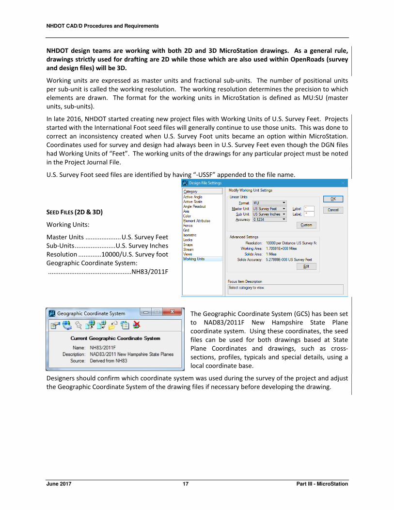
In late 2016, NHDOT started creating new project files with Working Units of U.S. Survey Feet. Projects
started with the International Foot seed files will generally continue to use those units. This was done to
correct an inconsistency created when U.S. Survey Foot units became an option within MicroStation.
Coordinates used for survey and design had always been in U.S. Survey Feet even though the DGN files
had Working Units of “Feet”. The working units of the drawings for any particular project must be noted
in the Project Journal File.
U.S. Survey Foot seed files are identified by having “-USSF” appended to the file name.
SEED FILES (2D & 3D)
Working Units:
Master Units .................... U.S. Survey Feet
Sub-Units ....................... U.S. Survey Inches
Resolution ............. 10000/U.S. Survey foot
Geographic Coordinate System:
...............................................NH83/2011F
The Geographic Coordinate System (GCS) has been set
to NAD83/2011F New Hampshire State Plane
coordinate system. Using these coordinates, the seed
files can be used for both drawings based at State
Plane Coordinates and drawings, such as cross-
sections, profiles, typicals and special details, using a
local coordinate base.
Designers should confirm which coordinate system was used during the survey of the project and adjust
the Geographic Coordinate System of the drawing files if necessary before developing the drawing.
NHDOT CAD/D Procedures and Requirements
Part III - MicroStation 18 June 2017
FONTS
MicroStation font resource files are binary files created from font cells, TrueType, Postscript, or
AutoCAD SHX fonts. MicroStation will read multiple font resource files according to the paths set by the
MS_SYMBRSC configuration variable in the selected workspace. However, within MicroStation they are
compiled into a list of all the fonts from all the resource files that were found. If one file contains a font
with the same number assigned as another font resource file, the user will see the last one located.
The NHDOT font resource files are called nh-custom-font.rsc & nhttfont.rsc. Any fonts within the NHDOT
resource files that are no longer in use will be maintained for backward compatibility purposes. The
fonts contained within the NHDOT resource files are described below. Font numbers below 170 are
reserved for standard MicroStation fonts.
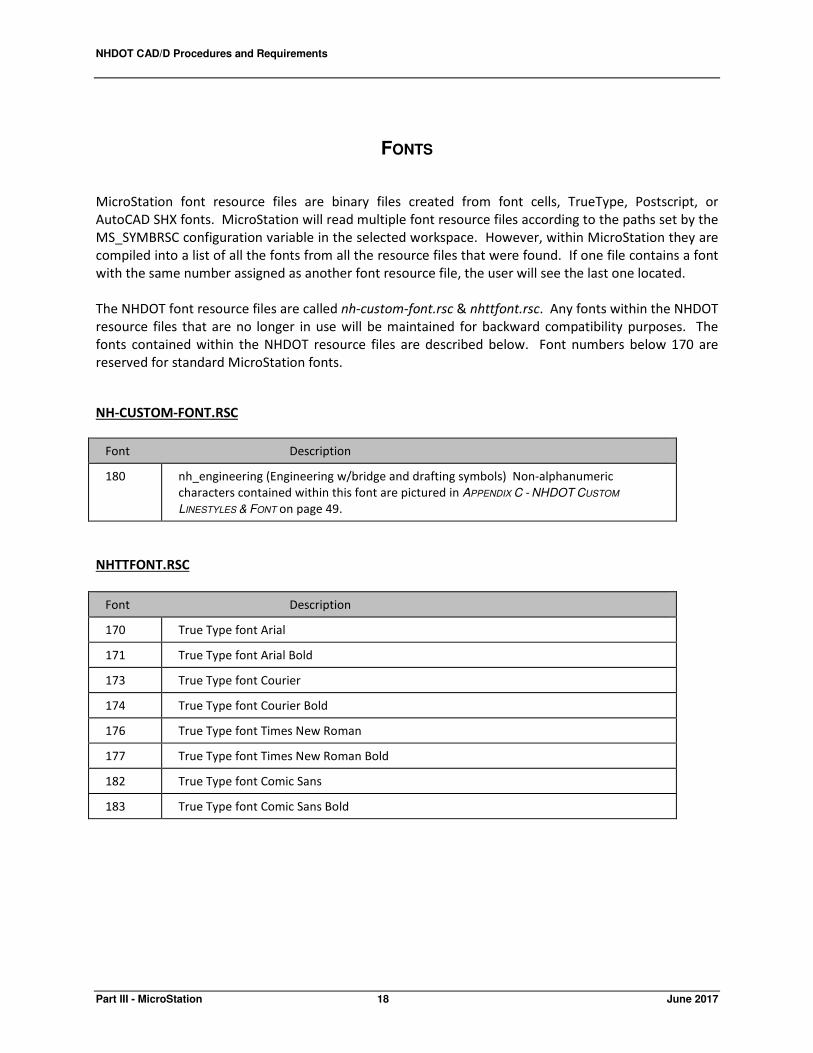
NH-CUSTOM-FONT.RSC
Font Description
180 nh_engineering (Engineering w/bridge and drafting symbols) Non-alphanumeric
characters contained within this font are pictured in APPENDIX C - NHDOT CUSTOM
LINESTYLES & FONT on page 49.
NHTTFONT.RSC
Font Description
170 True Type font Arial
171 True Type font Arial Bold
173 True Type font Courier
174 True Type font Courier Bold
176 True Type font Times New Roman
177 True Type font Times New Roman Bold
182 True Type font Comic Sans
183 True Type font Comic Sans Bold

NHDOT CAD/D Procedures and Requirements
June 2017 19 Part III - MicroStation
TEXT HEIGHT AND SPACING
Standard text heights and fonts have been defined to ensure uniformity and legibility on all CAD/D
drawings. The correct text height is shown on the level mapping table and is dependent on the plot
scale. Note that the text height listed represents both the text height and width. Since, the most
important issue with text is that it should be legible, font and text height may vary if absolutely
necessary. Text line spacing varies between half of the text height and the text height depending on the
use.
TEXT STYLES
For bridge drawings, text styles are available at various engineering and architectural scales. The styles
are located within nhdotTextandDimStyleLibraryFT.dgnlib (Imperial).
These dgnlib’s should be defined by the MS_DGNLIBLIST variable. The style names include the intended
purpose of the text and the scale of the drawings they will be used on.
nh_eng Used for note and detail text
Title nh_eng Used for detail title text
Note Title nh_eng Used for a smaller or sub-title text
Dimension and text style libraries used by Bridge Design are available on the NHDOT CAD/D website.
NHDOT CAD/D Procedures and Requirements
Part III - MicroStation 20 June 2017
LINESTYLES
Line style is part of the symbology of graphical elements in MicroStation. An element can be set to the
standard MicroStation linestyles (numbered 0 - 7) or to a custom linestyle defined in a custom linestyle
resource file. Custom linestyles are user definable resource files for the display of different patterns, for
example, a tree line, fence line, guardrail, etc. When an element is drawn in MicroStation with a custom
linestyle, the definition of the linestyle is not contained within the design file. The resource file from
which it was selected must be packaged with the design file and it must be found by MicroStation's
configuration in order to properly display the line. Therefore, users are strongly discouraged from
creating their own custom linestyles. Use the NHDOT supplied custom linestyle resources whenever
practical. Graphical depictions of NHDOT MicroStation linestyles are shown in APPENDIX C - NHDOT
CUSTOM LINESTYLES & FONT on page 49.
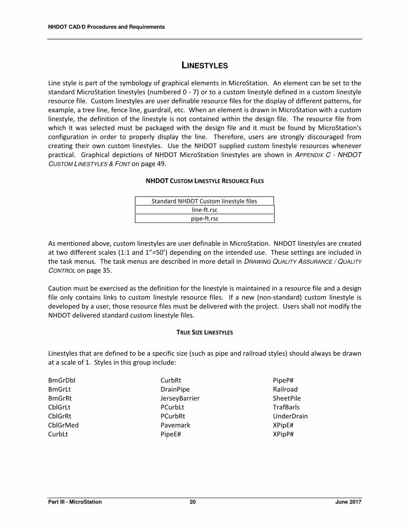
NHDOT CUSTOM LINESTYLE RESOURCE FILES
As mentioned above, custom linestyles are user definable in MicroStation. NHDOT linestyles are created
at two different scales (1:1 and 1”=50’) depending on the intended use. These settings are included in
the task menus. The task menus are described in more detail in DRAWING QUALITY ASSURANCE / QUALITY
CONTROL on page 35.
Caution must be exercised as the definition for the linestyle is maintained in a resource file and a design
file only contains links to custom linestyle resource files. If a new (non-standard) custom linestyle is
developed by a user, those resource files must be delivered with the project. Users shall not modify the
NHDOT delivered standard custom linestyle files.
TRUE SIZE LINESTYLES
Linestyles that are defined to be a specific size (such as pipe and railroad styles) should always be drawn
at a scale of 1. Styles in this group include:
BmGrDbl
BmGrLt
BmGrRt
CblGrLt
CblGrRt
CblGrMed
CurbLt
CurbRt
DrainPipe
JerseyBarrier
PCurbLt
PCurbRt
Pavemark
PipeE#
PipeP#
Railroad
SheetPile
TrafBarls
UnderDrain
XPipE#
XPipP#
Standard NHDOT Custom linestyle files
line-ft.rsc
pipe-ft.rsc

NHDOT CAD/D Procedures and Requirements
June 2017 21 Part III - MicroStation
SCALED LINESTYLES
Linestyles for plan drawings have been created for use on a 1”=50' scale Imperial drawing. This includes
most of the linestyles available. When these linestyles are used on 1"=20' Imperial drawings, they
should be scaled by 0.4. Charts showing scale values for other drawing scales are shown below.
CUSTOM LINESTYLE SCALING CHARTS
Imperial
Scale for
plotting
Ratio Custom
linestyle
scale
setting
1”=1” 1:1 0.0016
6”=1' 1:2 0.003
3”=1' 1:4 0.006
2”=1' 1:6 0.01
11/2” = 1' 1:8 0.013
1” = 1' 1:12 0.02
3/4” = 1' 1:16 0.026
1/2” = 1' 1:24 0.04
3/8” = 1' 1:32 0.053
1/4” = 1' 1:48 0.08
1" = 5' 1:60 0.1
3/16” = 1' 1:64 0.1066
1/8” = 1' 1:96 0.16
1” = 10' 1:120 0.2
3/32” = 1' 1:128 0.2135
1/16” = 1' 1:192 0.32
1” = 20' 1:240 0.4
1” = 30' 1:360 0.6
1” = 50' 1:600 1
1” = 100' 1:1200 2

NHDOT CAD/D Procedures and Requirements
Part III - MicroStation 22 June 2017
LINESTYLES CREATED AT 1:1
The line-ft.rsc file also contains custom linestyles created at a scale of 1:1. In order for these lines to be
properly proportioned, the user must enter the scale associated with the plot size of the drawing in the
Linestyles dialog box for custom linestyles before placing the line. The linestyles for which this rule
applies include:
ArBegOpn
ArBegSld
ArEndOpn
ArEndSld
ArrowBr
BreakBr
BreakDimBr
DimBr
GroundBr
ITS-Prop
LeaderBr
LedgeBr
RocklineBr
There are multiple ways to alter the scale of linestyles on a drawing. To set the scale, select Element →
Line Style → Custom. Select the linestyle, check the "Scale factor" box and enter the desired scale. Click
on the graphic representation of the linestyle to implement the change. An alternative way is to issue
the key-in dwg celtscale # where the # is replaced with the desired scale. Future lines will be drawn at
the new scale. To alter the scale of linestyles that have already been drawn, select all the elements to
be changed. Issue the Change Linestyle Scale # key-in replacing the # with the desired scale.
COLOR TABLE
A standard color table is necessary to provide visual consistency thus allowing users to easily identify
elements in shared files and for consistency in color plotting. NHDOT has its own default color table
called nh-color.tbl. The table defines 256 colors from which an active color can be selected and applied
to an element. NHDOT’s black and white plotters are configured to print all colors except 10-14 in black.
Colors 10-14 will plot in the shades of gray displayed in MicroStation.
CROSS HATCHING
Cross-hatching used by Bridge Design is shown on the next page.

NHDOT CAD/D Procedures and Requirements
June 2017 23 Part III - MicroStation

NHDOT CAD/D Procedures and Requirements
Part III - MicroStation 24 June 2017
CELL FILES
The following graphic cell files have been created for use on NHDOT projects. Items shown in italics
have been added since the previous edition.
alignment.cel symbols for alignment transfers
and ms tasks
borders.cel cut sheet borders (including front
sheets, ROW summary, property
layout and xsection borders and
their text cells)
br_Borders.cel miscellaneous bridge borders
br_bore.cel boring sheet symbols
br_Misc.cel rip-rap, slope lines, waterstops,
sheet piles, section A-A, North
arrow, shear connector, & RR
section
br_pile.cel HP sections and Pile Key
br_precast.cel New England Bulb Tees (precast
concrete beams)
br_Rail.cel 2 bar, 3 bar aluminum and T2,3,4
steel bridge and approach rails
br_Railmisc.cel existing/superseded, temporary,
and Texas 101 bridge and
approach rails
br_weld.cel weld symbols
drainage.cel proposed drainage detail cells
environ.cel environmental detail cells
exist-in.cel existing topography cells
geotech.cel geotechnical cells
grdrail.cel proposed guardrail detail cells
legends.cel hearing plan legends
logos.cel NHDOT and other logos
notes.cel project begin/end notes
pavemark.cel proposed pavement marking
detail cells
profile.cel cells for profile drawings
row.cel proposed right-of-way detail cells
signals.cel proposed signalization detail cells
signs.cel proposed sign detail cells
stamps.cel miscellaneous roll/plan sheet
cells
StnOffset.cel Station–Offset macro cells
turnrad.cel Imperial turning radii templates
utility.cel proposed utility detail cells
xsect.cel cross-section detail cells
The following pattern cell file has been created for use on NHDOT projects.
nhpatern.cel hearing plan removal patterns
Cells from Bentley's archpa.cel may also be used.
Additional cell files used for OpenRoads are included in the OpenRoads section.
NHDOT CAD/D Procedures and Requirements
June 2017 25 Part III - MicroStation
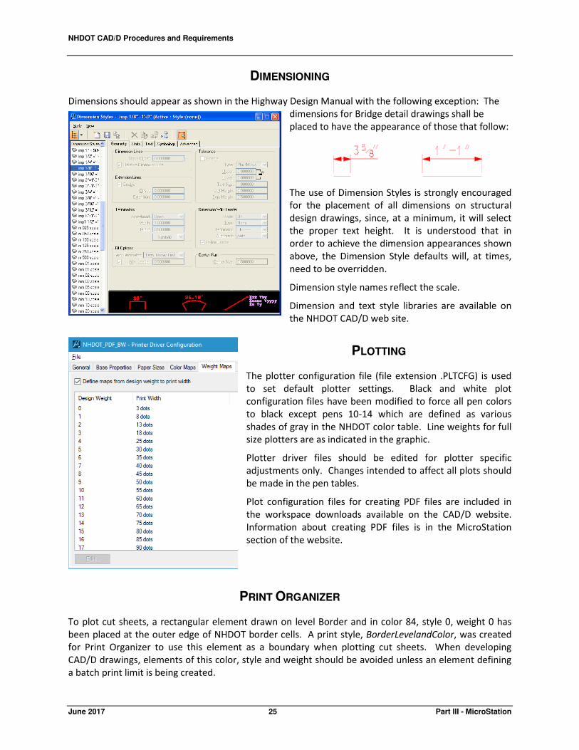
DIMENSIONING
Dimensions should appear as shown in the Highway Design Manual with the following exception: The
dimensions for Bridge detail drawings shall be
placed to have the appearance of those that follow:
The use of Dimension Styles is strongly encouraged
for the placement of all dimensions on structural
design drawings, since, at a minimum, it will select
the proper text height. It is understood that in
order to achieve the dimension appearances shown
above, the Dimension Style defaults will, at times,
need to be overridden.
Dimension style names reflect the scale.
Dimension and text style libraries are available on
the NHDOT CAD/D web site.
PLOTTING
The plotter configuration file (file extension .PLTCFG) is used
to set default plotter settings. Black and white plot
configuration files have been modified to force all pen colors
to black except pens 10-14 which are defined as various
shades of gray in the NHDOT color table. Line weights for full
size plotters are as indicated in the graphic.
Plotter driver files should be edited for plotter specific
adjustments only. Changes intended to affect all plots should
be made in the pen tables.
Plot configuration files for creating PDF files are included in
the workspace downloads available on the CAD/D website.
Information about creating PDF files is in the MicroStation
section of the website.
PRINT ORGANIZER
To plot cut sheets, a rectangular element drawn on level Border and in color 84, style 0, weight 0 has
been placed at the outer edge of NHDOT border cells. A print style, BorderLevelandColor, was created
for Print Organizer to use this element as a boundary when plotting cut sheets. When developing
CAD/D drawings, elements of this color, style and weight should be avoided unless an element defining
a batch print limit is being created.
NHDOT CAD/D Procedures and Requirements
Part III - MicroStation 26 June 2017
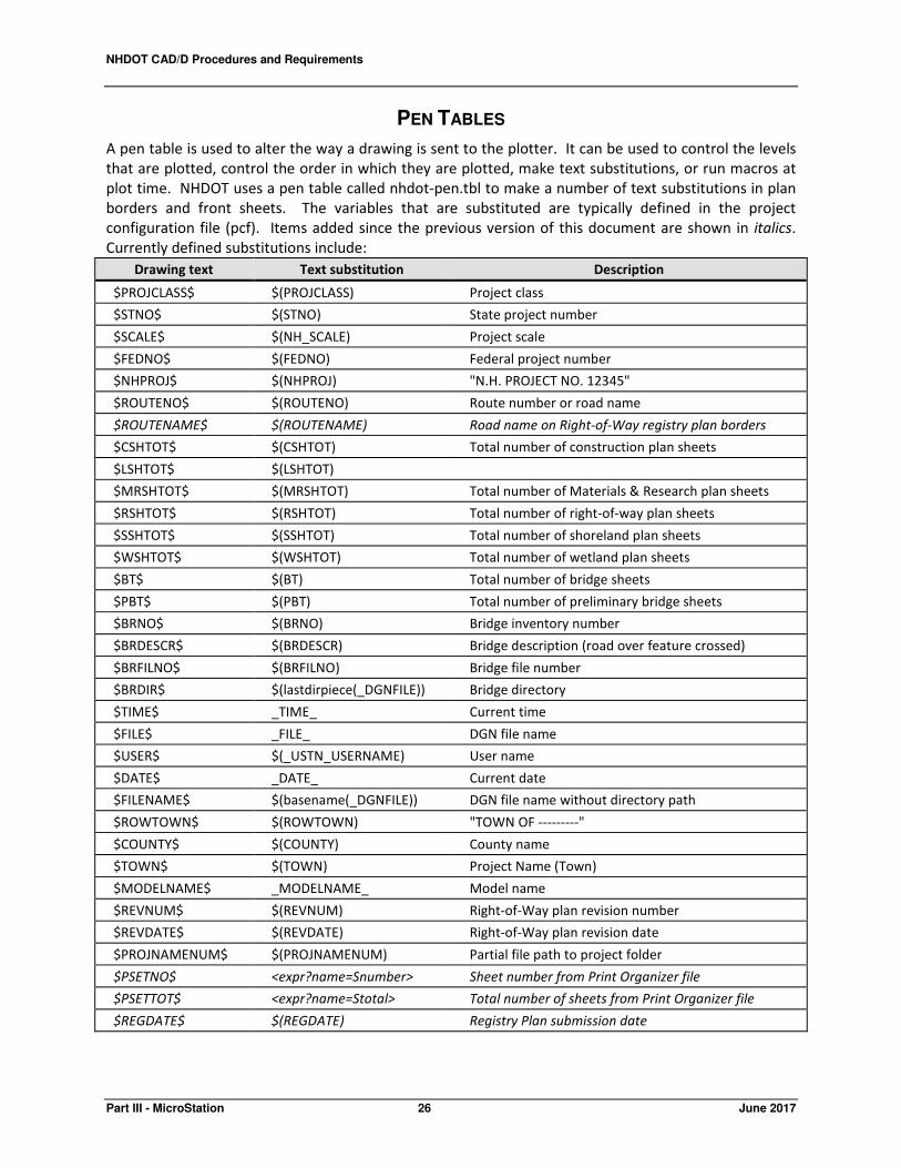
PEN TABLES
A pen table is used to alter the way a drawing is sent to the plotter. It can be used to control the levels
that are plotted, control the order in which they are plotted, make text substitutions, or run macros at
plot time. NHDOT uses a pen table called nhdot-pen.tbl to make a number of text substitutions in plan
borders and front sheets. The variables that are substituted are typically defined in the project
configuration file (pcf). Items added since the previous version of this document are shown in italics.
Currently defined substitutions include:
Drawing text Text substitution Description
$PROJCLASS$ $(PROJCLASS) Project class
$STNO$ $(STNO) State project number
$SCALE$ $(NH_SCALE) Project scale
$FEDNO$ $(FEDNO) Federal project number
$NHPROJ$ $(NHPROJ) "N.H. PROJECT NO. 12345"
$ROUTENO$ $(ROUTENO) Route number or road name
$ROUTENAME$ $(ROUTENAME) Road name on Right-of-Way registry plan borders
$CSHTOT$ $(CSHTOT) Total number of construction plan sheets
$LSHTOT$ $(LSHTOT)
$MRSHTOT$ $(MRSHTOT) Total number of Materials & Research plan sheets
$RSHTOT$ $(RSHTOT) Total number of right-of-way plan sheets
$SSHTOT$ $(SSHTOT) Total number of shoreland plan sheets
$WSHTOT$ $(WSHTOT) Total number of wetland plan sheets
$BT$ $(BT) Total number of bridge sheets
$PBT$ $(PBT) Total number of preliminary bridge sheets
$BRNO$ $(BRNO) Bridge inventory number
$BRDESCR$ $(BRDESCR) Bridge description (road over feature crossed)
$BRFILNO$ $(BRFILNO) Bridge file number
$BRDIR$ $(lastdirpiece(_DGNFILE)) Bridge directory
$TIME$ _TIME_ Current time
$FILE$ _FILE_ DGN file name
$USER$ $(_USTN_USERNAME) User name
$DATE$ _DATE_ Current date
$FILENAME$ $(basename(_DGNFILE)) DGN file name without directory path
$ROWTOWN$ $(ROWTOWN) "TOWN OF ---------"
$COUNTY$ $(COUNTY) County name
$TOWN$ $(TOWN) Project Name (Town)
$MODELNAME$ _MODELNAME_ Model name
$REVNUM$ $(REVNUM) Right-of-Way plan revision number
$REVDATE$ $(REVDATE) Right-of-Way plan revision date
$PROJNAMENUM$ $(PROJNAMENUM) Partial file path to project folder
$PSETNO$ <expr?name=Snumber> Sheet number from Print Organizer file
$PSETTOT$ <expr?name=Stotal> Total number of sheets from Print Organizer file
$REGDATE$ $(REGDATE) Registry Plan submission date

NHDOT CAD/D Procedures and Requirements
June 2017 27 Part IV - OpenRoads
PART IV – OPENROADS
INTRODUCTION
Bentley’s decision to replace their three different Civil Design software packages, (MX, InRoads and
Geopak), with OpenRoads provide the opportunity for NHDOT staff to exchange Civil Design data with
consultants regardless of which package they used. NHDOT has been aggressively testing and internally
promoting the use of OpenRoads updates as they are released. Consulting firms should be aware that
software updates are likely to occur in between updates to this document. When receiving a new
project, one should check with the Project Manager or CAD/D staff to confirm which version of the Civil
Software was used for the project’s design up to that point.
NHDOT has begun providing 3D design data to construction contractors for use in electronic field survey
equipment and GPS-guided construction vehicles. The transition from MX design to OpenRoads has
provided more complete 3D designs for these projects.
FILE NAMING
OpenRoads files should be named in such a way that someone unfamiliar with the project can figure out
what the file is for. Similar to MicroStation drawings, OpenRoads file names should always begin with
the project number.
SEED FILES
OpenRoads seed files vary from those used by MicroStation. The primary difference is the inclusion of a
3D model in the OpenRoads seed files. Additional details can be found in the MicroStation SEED FILES
section on page 16.
OPENROADS DRAWING NAMES
A naming convention for OpenRoads drawings has been established. To reduce the potential for errors
and conflicting data, this information is not included in this document. The current naming conventions
can be found within the OpenRoads section of the CAD/D web-site at the address listed in the DISCLAIMER
section of this document.
TEMPLATE FILES
Templates are used to create corridors. Each template is basically a typical section that contains the
features and components that are extruded along a civil geometry. Since each project is unique and will
likely need modification to any standard template, a “seed” template file has been created -
00000NHDOT-IMP.itl which contains templates developed by the NHDOT. When working in a new
project, 00000NHDOT-IMP.itl should be copied into appropriate folder for that project. When using MX,

NHDOT CAD/D Procedures and Requirements
Part IV - OpenRoads 28 June 2017
that is the project’s /MX/imperial_styles directory. InRoads and Geopak likely have their own location
for this file. The file would then be renamed to replace the “00000” with the state project number. The
template files obtain their component feature definitions from two dgnlib files, RWDSC.DGNLIB and
RWDSC2.DGNLIB. Roadway linear feature definitions come from the NHDOT-Road-Features.dgnlib.
OPENROADS CELL FILES & LINESTYLES
3D linestyles which can be used in OpenRoads and for the Subsurface Utility Engineering features are
still being developed. These linestyles are used to represent linear features such as guard rails in 3D
views. Once they are ready, they will be available for download from the CAD/D website.
The 3D linestyles which are available as of this writing are contained within two resource files -gr-
post.rsc and Civil_Custom_Linestyles_PVM.rsc. Additional linestyles will be available for download as
they are developed.
CIVIL CELLS
Sample Civil Cells for driveways and side roads are available in nhdot-civil-cells.dgnlib which is included
in the files available for download from the CAD/D website. Additional libraries will be added in the
future.
MX-SPECIFIC NOTES
Although NHDOT is moving away from MX design to OpenRoads, this information is being retained for
reference when working on older projects.
MX FILE NAMING
MX projects are typically given names beginning with the town name followed by the state project
number. For example: Concord 12345.mmd. It is not uncommon for the MMD file name to also include
an indication of the MX version being used for the design, i.e. Concord 12345 SS4.mmd. Other file types
are listed in the table below.
Type Extension Portability Description
Input .INP MX Only Used to store line mode commands to create or modify
MX strings
Output .PRN MX Only Used to store the results of an input file or interactive
commands
Draw .DRW MX Only An input file that is used to create a display using a
drawing macro or major option DRAW and/or ENHANCE
commands
Journal .JOU MX Only A journal file stores commands issued during an MX
session so they can be rerun at a later time

NHDOT CAD/D Procedures and Requirements
June 2017 29 Part IV - OpenRoads
MX MODEL NAMING
Suggested MX model names are listed in APPENDIX D – MX Model Naming Convention, on page 53. Any
variations from this convention shall be noted in the project journal file.
MX STRING LABELING
MX data is contained in strings and the strings are contained in models. Each string has a unique four-
character label. Typically the first two characters of the string label are used to identify the type of
string. NHDOT's string labeling convention can be found in the MX section of the CAD/D website at the
address listed in the DOCUMENTATION section on page 7.
MX STYLE SETS
A style set is a collection of styles which is used to draw a complete model or a selected part of it.
Beginning with MX v8i, style set references to MX macro symbols and macro lines have been replaced
with MicroStation cell and linestyle references. NHDOT style and features sets are stored on the
network in MX's Public folder so they are accessible to all users. This eliminates the need to upgrade
each workstation when changes are made.
MX FEATURE SETS
Feature sets are a means of grouping strings and identifying them with a description. They are used
throughout MX to make it easier to select strings for subsequent operations. The strings belonging to a
feature set are specified using a partial string name, and are drawn with a style set (usually having the
same name as the feature set).
For design detail, NHDOT uses a modified version of mxroad.fns provided by Bentley to conform to MX
design wizards. When transferring detail between MX and MicroStation, be aware that MicroStation
elements are drawn based on the model's default style set. This should be the same style set that was
used to draw the MX DPW/DPF.
The MX style sets are also used to display OpenRoads survey detail until OpenRoads Designer is
implemented. When transferring OpenRoads alignments to and from MX, OpenRoads.pss and
OpenRoads.fns should be set as the style and feature sets.
A table of NHDOT MX style and feature sets is on the MX section of the CAD/D website.
CROSS-SECTION SETTINGS FILES
Cross sections and profiles can be generated in a number of different ways. Using the cross-section
wizard within MX allows the user to save parameters defining the cross-section set. These saved
settings files have a .CSU extension and are stored in the project directory. The settings file will define
the type of sections cut (based on the cross-section feature set used), models selected, and information
about any special stations or skewed sections. By default, the cross-section wizard uses the information
in the cross section model's default style set to determine the different types of cross-sections. String
labels for cross sections are listed in APPENDIX G – CROSS SECTION SET LABELS on page 57. For NHDOT
projects, the default cross-section style set and feature set are listed in the table on the previous page.

NHDOT CAD/D Procedures and Requirements
Part IV - OpenRoads 30 June 2017
ADD-INS
MX Add-Ins are applications such as Visual Basic programs that can interact with MX. NHDOT has
developed a number of these programs to simplify some operations. These programs and their
descriptions are available on the CAD/D website.

NHDOT CAD/D Procedures and Requirements
June 2017 31 Part V – Procedures
PART V – PROCEDURES
INTRODUCTION
This section offers summaries of some NHDOT CAD/D procedures. It is not intended to provide an in-
depth discussion of any particular topic. For more details, refer to the CAD/D website.
EXCHANGING RIGHT-OF-WAY DATA
Right-of-way data is routinely updated during the project's lifetime. This information is typically
maintained by the NHDOT Bureau of Right-Of-Way for both in-house and Consultant-designed projects.
Knowing that DOT staff and Consultants both need to work on the existing right-of-way drawings, a
process has been developed to ensure that this data is kept current and accurate.
The existing right-of-way information will be divided between multiple drawings. One contains the line
work (ERL) a second will have the text information (ERT). Some projects may also have a third drawing
containing digitized right-of-way information (ERD). It is intended that the Department will maintain the
master ERL drawing (abstracting) and send the consultant a copy when updates have been made.
The Bureau of Right-Of-Way will continue to utilize Design History and that record will be maintained
throughout the life of the project. This is in line with how business was conducted when the process
included the ROW Abstracting mylar. The Bureau of Right-Of-Way will continue business as usual with
the ability to make changes at any time during the design process with the understanding that the
NHDOT Consultant Reviewer will be notified when changes have been made.
The process shall be:
• ERT and ERL drawings are created by the Bureau of Right-Of-Way and Design History is turned
on. Under normal circumstances, only the NHDOT Bureau of Right-Of-Way should be making
changes to the ERL drawing.
• The Consultant receives a copy of the ERT drawing. At their discretion, the Consultant is free to
adjust text position or make other cosmetic changes to improve legibility of the drawings.
• Updates to parcel ownerships made by the NHDOT abstractors are revised on the ERT
drawing and a copy of the updated ERT drawing is sent to the Consultant. The Consultant
will be responsible for updating their copy of the ERT drawing. Design History can be used
to highlight changes and text revisions made to the ERT drawing by NHDOT staff.
• The Consultant also receives a copy of the ERL drawing which is referenced into other drawings
(Not copied or merged).
• Updates to property lines, ROW lines, easement lines etc. are made to the ERL.dgn by
NHDOT Bureau of Right-Of-Way staff and a copy is sent to the Consultant. The revised
ERL.dgn supercedes all previous versions.
• Updates to the ERL.dgn can be reviewed using the Design History to identify changes and
impacts to the property line and ROW line locations

NHDOT CAD/D Procedures and Requirements
Part V – Procedures 32 June 2017
• Right-of-way data is submitted in both paper and DGN format to NHDOT Bureau of Right of Way
for review and approval prior to the production of recordable plans.
LEGACY ALIGNMENTS
Prior to the implementation of a CAD/D system in the 1980’s, it was customary to show alignments of
former projects on plan drawings as a reference between the old and new projects. Computer-aided
design, electronic survey equipment and advancement in GPS technology eliminated the need to
reference former alignments when creating new ones. As a result, former project data was no longer
shown on the plan drawings.
The Bureau of Right-of-Way has expressed a need to reference this historical information to facilitate
the locating of right-of-way boundaries that were laid out during these former projects. To assist this
process, future projects are to include information about these “legacy” alignments. Whenever
possible, this information should also be added to current projects.
The process includes:
• Researching former projects to identify those within the limits of the current project. On
consultant projects, the Bureau of Right-of-Way will do the research.
• Obtaining alignment information from the as-built plans.
• Drafting that information onto the alignment drawing of the current project.
USING OPENROADS TEMPLATES
Templates within the NHDOT-developed 00000NHDOT-IMP.itl can be modified as necessary to facilitate
design of the project.
When templates from the template library are applied to the assigned horizontal and vertical geometry
of a corridor, they are copied, not referenced, from the template library into the design file and are
assigned station ranges. It is possible to drop different templates at defined station ranges to achieve
changes in the roadway design. The template drop interval is the spacing that final templates will be
dropped. Set this at a value appropriate for the project. For automated machine guidance construction,
a rule of thumb is 5-ft between points on horizontal and vertical tangents and 1-ft between points
where there is horizontal or vertical curvature or widening. Data points are also required at key
stations, including horizontal and vertical geometry points, superelevation stations, offset geometry
points, drainage facilities and guardrail and barrier limits.1
ROLL PLANS
Project “roll-plan” file names are composed of three parts; the NHDOT state project number (first five
characters), drawing type (last three characters), and the .DGN file extension.
1 Recommendation from FHWA EDC-3 initiative “3D Engineered Models: Schedule, Cost and Post-Construction”

NHDOT CAD/D Procedures and Requirements
June 2017 33 Part V – Procedures
A further explanation of standard naming conventions and drawing type designators used by NHDOT
can be found in the MicroStation section of the CAD/D website at the address listed in the DISCLAIMER
section of this document.
CUT SHEETS
The Highway Design group at NHDOT presently uses a method for preparing cut sheets where a single
drawing is created for an entire set of drawings (general plans, drainage plans, etc.) with each sheet
stored in a different model within the drawing file.
The drawing file names will be the project number followed by the type of drawing such as
12345genplans.dgn for the general plans of project #12345. Within this file there will be models for
each individual sheet using the naming convention outlined in the following table. For example, the
model for the first general plan sheet will be called GEN01.
For more details of the processes for developing cut sheets, see the documentation in the MicroStation
section of the CAD/D website at the address listed in the DISCLAIMER section of this document.
Realizing that there are a number of different ways to accomplish this same task, variations to the
method described above may be acceptable with prior approval of NHDOT. Consultants wishing to use
an alternative method should contact the CAD/D Development Staff at the email address listed in the
DISCLAIMER section of this document. Any deviations from these formats shall be noted in the Project
Journal File. A listing of drawing type designators used by NHDOT is contained in the MicroStation
section of the CAD/D Website.
CROSS-SECTION DRAWINGS
With the transition to OpenRoads, cross-section drawings will be generated by OpenRoads and remain
in that format, not exported to a native MicroStation format like MX drawings were. That will allow for
updates to the cross sections if the design changes plus allow the ability to compute end area volumes
and apply cross section labeling tools. Additional annotation can be applied with MicroStation when
necessary.
Realizing that there are a number of different ways to accomplish this same task, variations to the
method described above may be acceptable with prior approval. Consultants wishing to use an
alternative method should contact the CAD/D development staff.
BRIDGE DETAIL SHEETS
A single detail sheet frequently requires the placement of several details of various scales. To
accomplish this, all details shall be drawn at a scale of 1:1 while using the NHDOT standard working units
defined within the NHDOT seed files. The detail sheet shall be composed by applying scale factors to
the self-referenced attachments of the detail drawing. The border of the detail sheet shall be a cell
placed on the drawing at a scale of 1. Detail drawings shall not be created by either increasing the scale
of the border or by temporarily adjusting the working units of the file, in any way.

NHDOT CAD/D Procedures and Requirements
Part V – Procedures 34 June 2017
NHDOT CAD/D Procedures and Requirements
June 2017 35 Part VI – Other Project Data
PART VI – OTHER PROJECT DATA
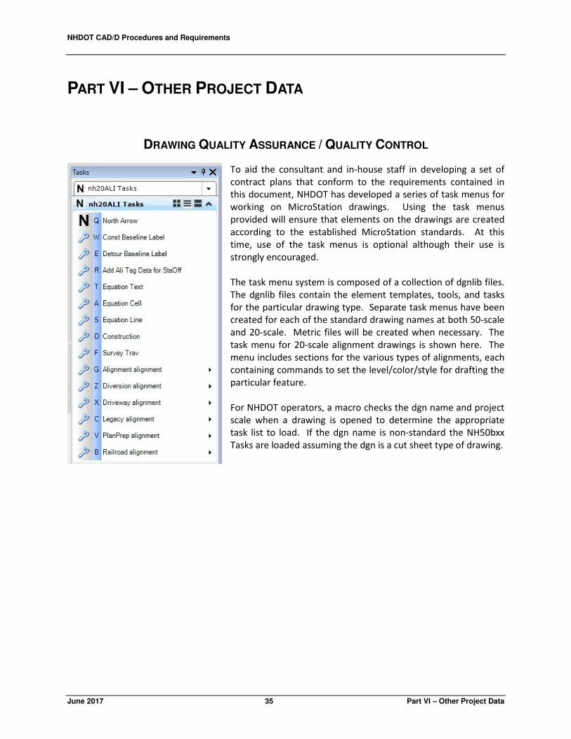
DRAWING QUALITY ASSURANCE / QUALITY CONTROL
To aid the consultant and in-house staff in developing a set of
contract plans that conform to the requirements contained in
this document, NHDOT has developed a series of task menus for
working on MicroStation drawings. Using the task menus
provided will ensure that elements on the drawings are created
according to the established MicroStation standards. At this
time, use of the task menus is optional although their use is
strongly encouraged.
The task menu system is composed of a collection of dgnlib files.
The dgnlib files contain the element templates, tools, and tasks
for the particular drawing type. Separate task menus have been
created for each of the standard drawing names at both 50-scale
and 20-scale. Metric files will be created when necessary. The
task menu for 20-scale alignment drawings is shown here. The
menu includes sections for the various types of alignments, each
containing commands to set the level/color/style for drafting the
particular feature.
For NHDOT operators, a macro checks the dgn name and project
scale when a drawing is opened to determine the appropriate
task list to load. If the dgn name is non-standard the NH50bxx
Tasks are loaded assuming the dgn is a cut sheet type of drawing.

NHDOT CAD/D Procedures and Requirements
June 2017 37 Part VII – Deliverable Requirements
PART VII - ENGINEERING CONSULTANT DELIVERABLE
REQUIREMENTS
OVERVIEW
The purpose of this section is to establish the minimum acceptable criteria for electronic CAD/D
deliverables. Obtaining drawings and ground models in a common format will reduce the amount of
time spent becoming familiar with the designs if they are transferred from one designer to another and
allows for their reuse in the future.
FILE FORMAT AND DELIVERY
REQUIREMENTS FOR SUBMITTING ELECTRONIC DATA TO NHDOT
All electronic data furnished to the NHDOT shall use the appropriate naming scheme and format for the
type of data to be transmitted. It is very important to clearly communicate what is being transmitted
and to describe the format of the transmitted files.
A letter is to be attached to all submissions stating briefly:
1. File content
2. File Format (zipped, MicroStation, OpenRoads, etc. and the utility used)
3. OpenRoads and/or MicroStation version
4. Number of CDs, DVDs, etc.
5. Files must be in the proper format before transmitting to NHDOT. No translating of
information by NHDOT personnel shall be required.
6. If files are zipped or backed up, a brief explanation of the recommended procedure to extract
the files should be included.
7. Versions of software must be current to or fully compatible with that of the NHDOT.
8. Each disk submitted shall be labeled and dated with a minimum of the State Project # and date.
If a series of CDs/DVDs are transmitted, the disk label shall also include the disk number and the
total CDs/DVDs of that set, (ex: 1 of 10). Other subsequent CDs/DVDs shall be labeled so as to
uniquely identify each group or set and shall include the sequence number followed by the total
number in the group (ex: 2 of 10, 3 of 10, etc.)
9. NHDOT reserves the right to reject any file transmitted that does not conform to these
requirements.
NHDOT CAD/D Procedures and Requirements
Part VII – Deliverable Requirements 38 June 2017
DATA SUBMISSION
In addition to hard copy drawings specified by the contract, the consultant shall submit electronic
drawing files in MicroStation .DGN file format. Contact the Project Manager for the preferred method
for submitting drawing files.
The final submission shall include all files necessary to reproduce the cut sheet drawings as well as
copies of the original “roll-plan” drawings used to generate the cut sheets. Documentation of
procedures and project history shall be maintained in a Project Journal File. An in-depth description of
the Project Journal File is in PART II – GENERAL CAD/D INFORMATION beginning on page 7. The Project
Journal File will be provided with the submission. Any drawings not included in the NHDOT standard
drawing list will be identified and will include a description of levels used on each drawing.
Detailed descriptions of the data to be provided by NHDOT to the consultant and expected deliverables
at various stages of the project's development begin on page 40.
If MicroStation tables for linestyles, multilines, level tables, symbology tables, database, special fonts, or
any special user defined feature is used, that information must be provided and shall become property
of NHDOT. Similarly, any civil design libraries developed by the consultant that are necessary to
properly display the project data shall become property of NHDOT. A name and description of each file
must also be provided. NHDOT will not distribute these items to any other individual, consultant or
State Transportation Department without prior permission of the developer.
INTERMEDIATE SUBMISSIONS
The consultant shall be prepared to submit sample cut sheet, profile, typical or detail, and/or cross-
section sheets for review of conformity to the NHDOT CAD/D specifications at various stages of the
project's development. As a minimum, the final design consultant should be prepared to submit
electronic project drawings at the Preliminary Plans, Specifications & Estimate (PPS&E) and PS&E stages
of the project. Depending on the project, NHDOT may request electronic submissions at a more or less
frequent interval.
Since numerous groups work together during the project's design, it is important that everyone uses the
same data. Therefore, when changes are made that would affect the design, updated drawings shall be
provided to the NHDOT Consultant Reviewer. These, in turn, will be distributed to all affected parties.
DEVIATION FROM FORMAT
Any file to be submitted that deviates from the above-mentioned DGN format must have prior NHDOT
approval. The approval must be in writing with the name of the individual from NHDOT who permitted
the varying format.

NHDOT CAD/D Procedures and Requirements
June 2017 39 Part VII – Deliverable Requirements
MICROSTATION ONLY DELIVERABLE
For projects that were initiated after April 18, 2002, NHDOT will only accept plan drawings that were
developed in MicroStation's DGN format. Translations from AutoCAD or any other CAD/D software will
no longer be allowed on those projects. Projects initiated before that date can continue to follow the
requirements in place at the time the project was initiated. Engineering consultants may, at their
discretion, choose to follow a subsequent release of these requirements.
RECORD OF DESIGN AS SUBMITTED (FINAL DESIGN CONSULTANTS ONLY)
In addition to MicroStation format drawings, plot files of project cut sheets in PDF format will be
required at the completion of the project. Plot files should be named with the convention for plan
sheets outlined in APPENDIX A - MICROSTATION DRAWING NAMES beginning on page 47 using a .PDF file
extension. The purpose of this requirement is to provide a viewable and reproducible copy of the
drawing as it existed at the end of the consultant contract.
FILE CONVERSION
This information only applies to projects initiated prior to April 18, 2002.
Translation tables, conversion tables, or special software programs have not been created or
standardized for exchanging information between common file formats such as DXF, DWG, ICES, IGES,
or software such as AutoCAD, ARCVIEW, ARCINFO, GDS, etc.
MicroStation provides methods for exchanging select file types but data is often modified during the
process. The Consultant is solely responsible for any translation and verification required to convert
non-MicroStation graphics files to the current NHDOT MicroStation design file format. All translated
design files shall conform to the standards adopted by NHDOT for electronic plans and the specifications
required in this document. Those files shall be converted to MicroStation and thoroughly reviewed prior
to transmitting to NHDOT.

NHDOT CAD/D Procedures and Requirements
Part VII – Deliverable Requirements 40 June 2017
INITIATING A DESIGN PROJECT
This section describes the data that is to be provided to a design consultant at the beginning of a
project.
The Plan Preparation section is responsible for taking project survey and preparing the digital terrain
model (DTM) and base drawings that will be used during the design process. They should also be the
ones to initiate the Project Journal File described in PART II – GENERAL CAD/D INFORMATION beginning on
page 7.
By default, NHDOT design teams are working with mostly 2D plan drawings. However, 3D versions of
survey detail and contour drawings are also being created. 3D terrain model drawings are being
created for use with OpenRoads.
Electronic data to be provided by the NHDOT Plan Preparation Section to:
Consultants using OpenRoads software:
1. Copy of the 2D and 3D DGN files containing survey data with Plan Preparation
modifications/enhancements.
2. 3D terrain model
3. Copy of MicroStation .DGN file containing annotation for survey detail.
4. Copy of the Project Journal File containing all pertinent information about the project.
Consultants without OpenRoads software:
1. LandXML files of existing detail and triangulation generated from the OpenRoads terrain or
MX model file
2. Copy of annotated MicroStation .DGN files developed for the project.
3. Copy of the Project Journal File containing all pertinent information about the project.
INTERIM PROJECT DELIVERABLES
This section describes the data that is to be provided when a project moves from one designer to the
next. This could be a transition between Preliminary Design and Final Design consultant designers or a
transition between NHDOT designers and consultants. Data received at this point will be provided to
the group continuing the design process.
Electronic deliverables expected from NHDOT Highway & Bridge Design staff and Consultants using
OpenRoads software:
1. Copy of the 2D and 3D DGN files containing processed survey data and terrain models
2. Copy of any templates necessary to recreate the submitted design
3. Copy of MicroStation .DGN files developed for the project
4. Copy of the Project Journal File containing all pertinent information about the project.
5. Copies of any MicroStation cell files and linestyle resource files used on the project that are
not included in the NHDOT standards.

NHDOT CAD/D Procedures and Requirements
June 2017 41 Part VII – Deliverable Requirements
From Consultants without OpenRoads software:
1. LandXML files of existing detail and triangulation generated from the design software
2. Copy of project horizontal and vertical alignments and associated design features in
LandXML formats. Descriptions of file transfer formats can be found in APPENDIX E – CIVIL
DATA TRANSFER FORMATS beginning on page 53
3. Copy of MicroStation .DGN files developed for the project
4. Copy of the Project Journal File containing all pertinent information about the project.
5. Copies of any MicroStation cell files and linestyle resource files used on the project that are
not included in the NHDOT standards.
Electronic data to be provided to the group continuing the design:
Consultants using OpenRoads software:
1. Copy of the 2D and 3D DGN files containing processed survey data and terrain models
2. Copy of OpenRoads design files
3. Copy of any templates necessary to recreate the submitted design
4. Copy of MicroStation .DGN files developed for the project
5. Copy of the Project Journal File containing all pertinent information about the project.
6. Copy of the Project Public Hearing Plan in PDF format
Consultants without OpenRoads software:
1. Copy of project horizontal and vertical alignments and associated design features in
LandXML format.
2. LandXML files of existing detail and triangulation generated from the OpenRoads terrain or
MX model file.
3. Copy of MicroStation .DGN files developed for the project
4. Copy of the Project Journal File containing all pertinent information about the project.
5. Copy of the Project Public Hearing Plan in PDF format
PROJECT COMPLETION
At the completion of a design project, the following list is a guide to what electronic information is
expected to be returned from the design Consultants to NHDOT for final storage. Additional
deliverables may be required if 3D design data is to be provided to the construction contractor. In this
instance, additional deliverables would be required to comply with Item 670.822 - GNSS Construction
Inspection Equipment. Check with the Project Manager for full details.
CAD/D FILE INFORMATION
CAD/D Data in MicroStation DGN Format
• Copy of MicroStation .DGN files developed for the project
NHDOT CAD/D Procedures and Requirements
Part VII – Deliverable Requirements 42 June 2017
• Include any files from sub-consultants (including Traffic Signals, Ret. Walls, ROW plans,
Mitigation sites, Soundwalls, etc…).
• Plotting references needed to re-produce project cut-sheets including sheet numbering
(include final project .pcf file, pen-tables, etc…)
• Files used to number the project cut-sheets (project .pcf file, pen tables, etc…).
• Copies of any cell files and linestyle resource files used on the project that are not included
in the NHDOT standards.
• Final embellished presentation plan for use by the Construction field office personnel.
Civil Design Data
• 3D terrain model surfaces (existing and proposed surfaces), triangulation models or dtm
surfaces developed by OpenRoads, InRoads, MX or Geopak for use by the Construction
Contractor.
• Copy of any templates necessary to recreate the submitted design.
• Copy of any OpenRoads, InRoads, MX or Geopak DGN files used to develop the final contract
plan drawings such as drawings containing alignments, profiles, corridors and subsurface
utility features.
• If the project was developed using MX, include a copy of the model file and any
style/feature sets developed for the project.
• If the project was developed using InRoads, see the additional requirements in PROJECTS
DESIGNED USING INROADS on page 44.
Spreadsheet Information
• All project quantity summary sheets in original format (Excel).
• All sign text sheet information in original format (Excel).
• All quantity sheet information in original format (Excel), to be used by Construction staff.
• All drainage note information in original format (Excel, Word, or .dgn), to be used by
Construction staff.
• All pollutant loading and related information in original format (Excel, Word, etc…).
• All design spreadsheets used to complete certain design elements (guardrail design, borings,
monitoring wells, etc…) in original format (Excel, Word, .dgn, etc…).
• All traffic analyses studies done during the project including any HCM analyses, traffic
simulation models, and presentation graphics.
• Any special quantity studies done during the project that could be useful in the future.
Drainage Information
• All Hydrocad Models in their original format (include index of models in the file).
• All Stormcad, Storm and Sanitary, HY8, Pond Pac, or Hydrain data in their original formats
include an index of the numbering sequence of tables).
• All watershed maps in their original format (GIS, .dgn, mapping software, etc…).
• All soil map information that was included in the pollutant loading package.
NHDOT CAD/D Procedures and Requirements
June 2017 43 Part VII – Deliverable Requirements
Project Image Files
The following plans are needed for the Department’s plan inventory:
• Provide final .pdf or .tif files of all project final design plan sheets included in the Proposal
Prints, in the following format: 12345POPXXXX.pdf where the “12345” is the project
number, the XXXX is the sheet number, and POP is the “plan of Proposed”, (i.e.
13933GPOP0001.pdf would be the front sheet number 0001 from the 13933G project
plans). This format matches the Department’s internal naming format for archiving. This
includes the Final Roadway plans, Final Bridge plans, etc…
• Provide final .pdf or .tif files of all project plan sheets included in the Proposal Prints, in the
following format: 12345ROWXXX.pdf where the “12345” is the project number, the XXX is
the sheet number, and ROW is the “Right-Of-Way”, (i.e. 13933GROWXXX.pdf would be
sheet number XXX from the 13933G project ROW plans). This format matches the
Department’s internal naming format for archiving. This includes the Final Roadway plans,
Final Bridge plans, etc…
The following additional plans are needed for use by the Department:
• Provide the Final Erosion Control Plans in .pdf or .tif files of all project final design erosion
control plan sheets in the following format: 12345ECPXXX.pdf where the “12345” is the
project number, the XXX is the sheet number, and ECP is the “erosion control plan”, (i.e.
13933GECPXXX.pdf would be sheet number XXX from the 13933G project erosion control
plans). This format is in keeping with the Department’s internal naming format for
archiving.
• Provide the Wetland Impact Plans in .pdf or .tif files of all project final design plan sheets in
the following format: 12345WETXXX.pdf where the “12345” is the project number, the XXX
is the sheet number, and WET is the “wetland impact”, (i.e. 13933GWETXXX.pdf would be
sheet number XXX from the 13933G project wetland impact plans). This format is in keeping
with the Department’s internal naming format for archiving. Roll plan .pdf files may also be
required depending on project specific’s (including scale and layout).
• Provide the Shoreland Impact Plans in .pdf or .tif files of all project final design plan sheets in
the following format: 12345SHOXXX.pdf where the “12345” is the project number, the XXX
is the sheet number, and SHO is the “Shoreland impact”, (i.e. 13933GSHOXXX.pdf would be
sheet number XXX from the 13933G project Shoreland impact plans). This format is in
keeping with the Department’s internal naming.
• Final embellished presentation roll plan for use by the Construction field office personnel in
.pdf form.
Project Photographs
• Provide electronic versions of all photograph’s taken during design of the project. This
would include any photo’s used in the Wetland Impact and Shoreland Impact application
process.
Project Journal File
• Care shall be taken to prepare a complete Project Journal File outlining all files and
descriptions used on the project. In addition to the cut-sheet definitions, all cut sheet
models need to be included so the sheets can be re-produced.

NHDOT CAD/D Procedures and Requirements
Part VII – Deliverable Requirements 44 June 2017
Text Files
• COGO and coordinate reports of each alignment similar in format to the ones shown in
APPENDIX F – CONSTRUCTION REPORTS on page 55 for use by NHDOT Survey section and the
Construction Contractor.
• Station and offset listing of proposed bounds.
• Complete index of all 3D model surfaces provided and what they are used for.
• Any information necessary to properly plot the drawings. Include any pen-tables used in the
project.
Additional Data
• Additional deliverables may be required if 3D design data is to be provided to the
construction contractor. In this instance, additional deliverables would be required to
comply with Item 670.822 - GNSS Construction Inspection Equipment. Check with the
Project Manager for full details.
PROJECTS DESIGNED USING INROADS
If a project is designed with InRoads the following files should be delivered as part of the electronic
deliverable:
InRoads Preferences (*.xin): This file will contain the settings used to control the display of
information as well as the default values displayed in InRoads dialogs for generating the
design graphics.
Surface data: (*.dtm): These files will contain existing and proposed surface information. This
information will include but is not limited to the surface triangulation. Other information
that will potentially be found in the DTM include planemetric features like: breaklines
representing existing and proposed objects, feature lines for entities like R.O.W. or
easements, as well as random point information that can depict features like catch basins,
mailboxes, or other single point features.
Alignment data (alg): This will contain all coordinate geometry and alignment information for
the project alignments.
Template Library file (*.itl): Contains the templates (Typical sections), cut and fill tables, material
tables, decision tables and transition control features. This is one of the building blocks
used in Roadway Designer.
Roadway designer files (*.ird): The roadway designer file will include the templates (Typical
sections) in addition to the roadway model definition, this is the “recipe” to build your
design. Items in this file include: superelevation, links to the alignments used in the design,
as well as the limits of design.
Survey data (*.fwd or other formats): If the survey for the project was completed by people
outside the department, then all data used to create the existing conditions plans should be

NHDOT CAD/D Procedures and Requirements
June 2017 45 Part VII – Deliverable Requirements
provided. If the survey was done in InRoads Survey, then the .fwd files that were imported
into InRoads Survey should be provided. If the survey was prepared with a different
software, then the data brought into InRoads should be provided in its original format.
Style Sheets (*.xsl): InRoads report style sheets used for reports included in the design should
also be delivered with the project.
Storm & Sanitary files (*.sdb): The design information entered into InRoads Storm & Sanitary
should also be included for the Department’s use. This will include location, sizes and
structure types for the drainage design.
Quantity Manager files (*.mdb): This file is the database containing the automatically generated
quantities from InRoads for the project.
SPECIALIZED DEVELOPMENT BY DESIGN CONSULTANTS
Any specialized programs, macros, utilities, symbology, etc., developed by the consultant that are
necessary to properly display drawings submitted to NHDOT shall be included with other project
deliverables.
Submission of copies of other specialized programs, macros, utilities, symbology, etc. developed to
improve the CAD/D drafting and design processes is encouraged. It is understood that NHDOT accepts
these items without any guarantee of usefulness or expectations of support by the developer. In
addition, NHDOT will not distribute these items to any other individual, consultant or State
Transportation Department without prior permission of the developer.
NHDOT RESOURCES AVAILABLE FOR CONSULTANTS
To assist in the production of the required CAD/D files, NHDOT has provided MX and MicroStation
support files available from the Department's web site. The website address is listed in the
DOCUMENTATION section on page 7. Many of the files that are available are described in the LEVEL
ASSIGNMENTS AND SYMBOLOGY section on page 15.


June 2017 47 Part VIII – Appendix
PART VIII - APPENDIX
APPENDIX A - MICROSTATION DRAWING NAMES
Note: MicroStation drawing information was included in previous editions of this document. To
reduce the potential for errors and conflicting data, this information has been removed. The
current list of drawing names can be found in the MicroStation section of the CAD/D website
at the address listed in the DISCLAIMER section of this document.
APPENDIX B - LEVEL MAPPING CONVENTION
Note: MicroStation level information was included in previous editions of this document. To reduce
the potential for errors and conflicting data, this information has been removed. The latest
mapping convention can be found on the NHDOT web-site at the address listed in the
DISCLAIMER section of this document. Previous versions of the level mapping will be
maintained on the website.


June 2017 49 Part VIII – Appendix
APPENDIX C - NHDOT CUSTOM LINESTYLES & FONT
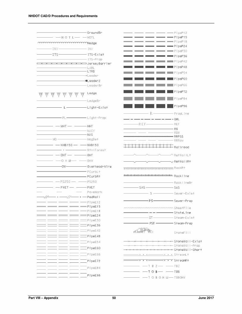
NHDOT CAD/D Procedures and Requirements
Part VIII – Appendix 50 June 2017

NHDOT CAD/D Procedures and Requirements
June 2017 51 Part VII – Deliverable Requirements
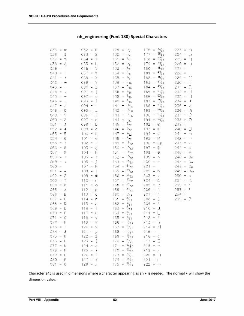
NHDOT CAD/D Procedures and Requirements
Part VIII – Appendix 52 June 2017
nh_engineering (Font 180) Special Characters
Character 245 is used in dimensions where a character appearing as an * is needed. The normal * will show the
dimension value.
NHDOT CAD/D Procedures and Requirements
June 2017 53 Part VII – Deliverable Requirements
APPENDIX D – MX MODEL NAMING CONVENTION
NHDOT is transitioning from MX to OpenRoads for Civil Design work. As a result, this section has been
retired. For information on the MX Model Naming Convention, please visit the NHDOT CAD/D
website at the address listed in the DISCLAIMER section of this document.
APPENDIX E – CIVIL DATA TRANSFER FORMATS
LANDXML
The use of LandXML is encouraged for transferring design data. LandXML was established to exchange design data
utilizing a non-proprietary data standard. LandXML is the easiest avenue for transferring alignments between
design softwares, including (but not limited to) OpenRoads, MX, InRoads, and Geopak.
Survey data and surface triangulations may also be transferred via LandXML. However at this time, there are still
limitations when transferring large models (surfaces). Therefore, it is strongly recommended to translate only
essential data.
Importing LandXML data to OpenRoads and exporting OpenRoads data to LandXML are documented on the
Department’s web site. Also, learn more about LandXML at www.LandXML.org.


NHDOT CAD/D Procedures and Requirements
June 2017 55 Part VII – Deliverable Requirements
APPENDIX F – CONSTRUCTION REPORTS
SAMPLE OPENROADS ALIGNMENT REPORT (COGO STYLE)
Horizontal Alignment Review Report
Report Created: 4/7/2017 3:20pm
Project: Unity 20262 Description: File Name: \Unity\20262\OpenRoads\FinalDesign\20262geometry.dgn Last Revised: 4/7/2017 15:20:37 Note: All units in this report are in feet unless specified otherwise.
Alignment Name: MC1M Alignment Description: Alignment Style: Alignment Station Northing Easting Element: Linear POB ( ) 506+00.000 473216.5314 1112416.8044 PC ( ) 518+98.666 474501.7220 1112603.3988 Tangential Direction: N 8°15'39.39" E Tangential Length: 1298.6655 Element: Circular PC ( ) 518+98.666 474501.7220 1112603.3988 PI ( ) 523+15.352 474913.6842 1112665.9685 CC ( ) 474680.4163 1111426.8662 PT ( ) 527+00.285 475274.6939 1112457.8825 Radius: 1190.0255 Delta: 38°35'43.23" Left Degree of Curvature (Arc): 15°47'46.16" Length: 801.6199 Tangent: 416.6867 Chord: 786.5498 Middle Ordinate: 66.8623 External: 70.8426 Tangent Direction: N 8°38'10.33" E Radial Direction: S 81°21'49.67" E Chord Direction: N 10°39'41.29" W Radial Direction: N 60°02'27.10" E Tangent Direction: N 29°57'32.90" W Element: Linear PT ( ) 527+00.285 475274.6939 1112457.8825 PI ( ) 551+97.003 477341.3433 1111056.9681 Tangential Direction: N 34°07'55.45" W Tangential Length: 2496.7180 Element: Linear PI ( ) 551+97.003 477341.3433 1111056.9681 POE ( ) 552+02.003 477338.4029 1111052.9241 Tangential Direction: S 53°58'46.85" W Tangential Length: 5.0000
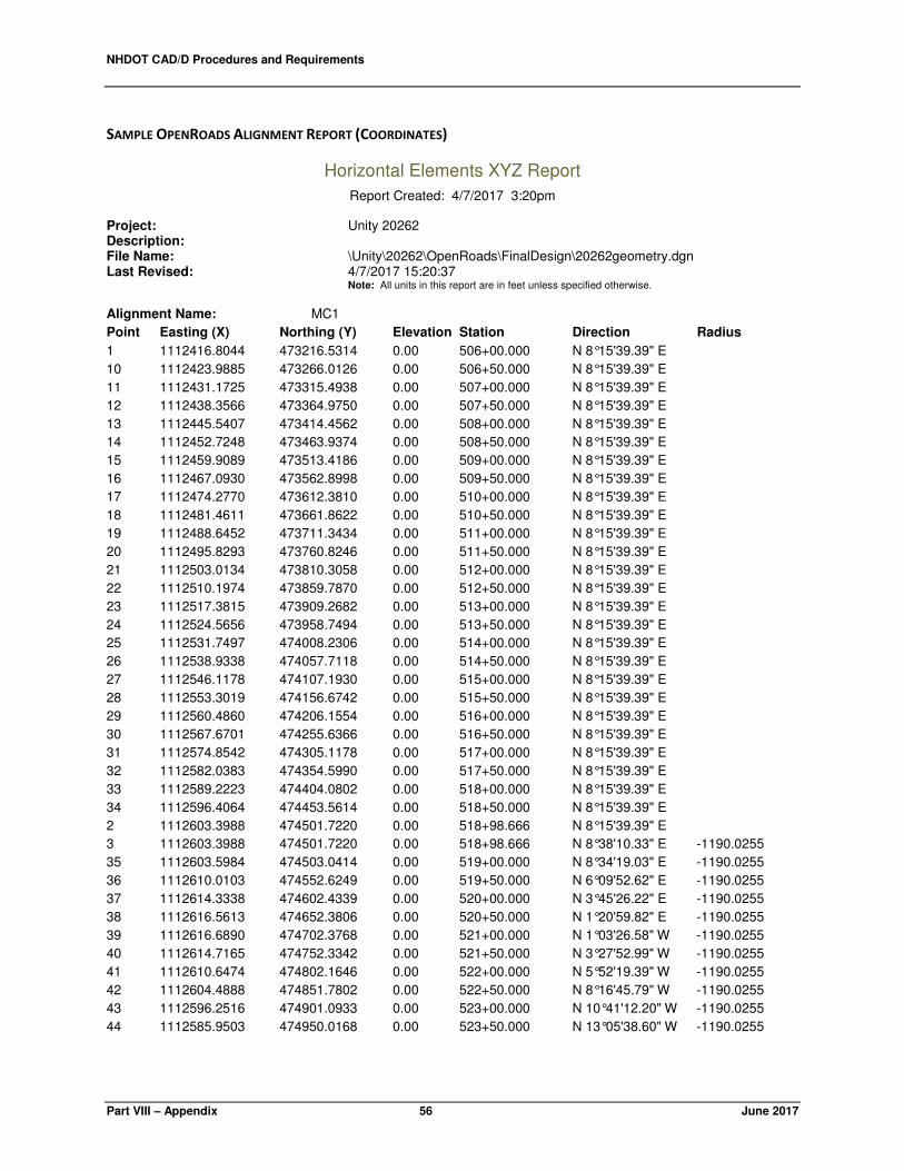
NHDOT CAD/D Procedures and Requirements
Part VIII – Appendix 56 June 2017
SAMPLE OPENROADS ALIGNMENT REPORT (COORDINATES)
Horizontal Elements XYZ Report
Report Created: 4/7/2017 3:20pm
Project: Unity 20262 Description: File Name: \Unity\20262\OpenRoads\FinalDesign\20262geometry.dgn Last Revised: 4/7/2017 15:20:37 Note: All units in this report are in feet unless specified otherwise.
Alignment Name: MC1
Point Easting (X) Northing (Y) Elevation Station Direction Radius
1 1112416.8044 473216.5314 0.00 506+00.000 N 8°15'39.39" E
10 1112423.9885 473266.0126 0.00 506+50.000 N 8°15'39.39" E
11 1112431.1725 473315.4938 0.00 507+00.000 N 8°15'39.39" E
12 1112438.3566 473364.9750 0.00 507+50.000 N 8°15'39.39" E
13 1112445.5407 473414.4562 0.00 508+00.000 N 8°15'39.39" E
14 1112452.7248 473463.9374 0.00 508+50.000 N 8°15'39.39" E
15 1112459.9089 473513.4186 0.00 509+00.000 N 8°15'39.39" E
16 1112467.0930 473562.8998 0.00 509+50.000 N 8°15'39.39" E
17 1112474.2770 473612.3810 0.00 510+00.000 N 8°15'39.39" E
18 1112481.4611 473661.8622 0.00 510+50.000 N 8°15'39.39" E
19 1112488.6452 473711.3434 0.00 511+00.000 N 8°15'39.39" E
20 1112495.8293 473760.8246 0.00 511+50.000 N 8°15'39.39" E
21 1112503.0134 473810.3058 0.00 512+00.000 N 8°15'39.39" E
22 1112510.1974 473859.7870 0.00 512+50.000 N 8°15'39.39" E
23 1112517.3815 473909.2682 0.00 513+00.000 N 8°15'39.39" E
24 1112524.5656 473958.7494 0.00 513+50.000 N 8°15'39.39" E
25 1112531.7497 474008.2306 0.00 514+00.000 N 8°15'39.39" E
26 1112538.9338 474057.7118 0.00 514+50.000 N 8°15'39.39" E
27 1112546.1178 474107.1930 0.00 515+00.000 N 8°15'39.39" E
28 1112553.3019 474156.6742 0.00 515+50.000 N 8°15'39.39" E
29 1112560.4860 474206.1554 0.00 516+00.000 N 8°15'39.39" E
30 1112567.6701 474255.6366 0.00 516+50.000 N 8°15'39.39" E
31 1112574.8542 474305.1178 0.00 517+00.000 N 8°15'39.39" E
32 1112582.0383 474354.5990 0.00 517+50.000 N 8°15'39.39" E
33 1112589.2223 474404.0802 0.00 518+00.000 N 8°15'39.39" E
34 1112596.4064 474453.5614 0.00 518+50.000 N 8°15'39.39" E
2 1112603.3988 474501.7220 0.00 518+98.666 N 8°15'39.39" E
3 1112603.3988 474501.7220 0.00 518+98.666 N 8°38'10.33" E -1190.0255
35 1112603.5984 474503.0414 0.00 519+00.000 N 8°34'19.03" E -1190.0255
36 1112610.0103 474552.6249 0.00 519+50.000 N 6°09'52.62" E -1190.0255
37 1112614.3338 474602.4339 0.00 520+00.000 N 3°45'26.22" E -1190.0255
38 1112616.5613 474652.3806 0.00 520+50.000 N 1°20'59.82" E -1190.0255
39 1112616.6890 474702.3768 0.00 521+00.000 N 1°03'26.58" W -1190.0255
40 1112614.7165 474752.3342 0.00 521+50.000 N 3°27'52.99" W -1190.0255
41 1112610.6474 474802.1646 0.00 522+00.000 N 5°52'19.39" W -1190.0255
42 1112604.4888 474851.7802 0.00 522+50.000 N 8°16'45.79" W -1190.0255
43 1112596.2516 474901.0933 0.00 523+00.000 N 10°41'12.20" W -1190.0255
44 1112585.9503 474950.0168 0.00 523+50.000 N 13°05'38.60" W -1190.0255
NHDOT CAD/D Procedures and Requirements
June 2017 57 Part VII – Deliverable Requirements
APPENDIX G – CROSS SECTION SET LABELS
Note: MX cross-section label information was included in previous editions of this document. To
reduce the potential for errors and conflicting data, this information has been removed. The
current list of cross-section information can be found in the MX section of the CAD/D website
at the address listed in the DISCLAIMER section of this document.